Embed Size (px)
Citation preview

Product Data
214DLegacyt Line Heat Pumpwith Puronr Refrigerant1---1/2 To 5 Nominal Tons
Bryant heat pumps with Puronr refrigerant provide a collection offeatures unmatched by any other family of equipment. The 214Dhas been designed utilizing Bryant’s Puron refrigerant. Theenvironmentally sound refrigerant allows consumers to make aresponsible decision in the protection of the earth’s ozone layer.
NOTE: Ratings contained in this document are subject tochange at any time. Always refer to the AHRI directory(www.ahridirectory.org) for the most up--to--date ratingsinformation.
INDUSTRY LEADINGFEATURES / BENEFITSEfficiencyS 14 SEER / 11.5 -- 11.7 EER / 8.2 HSPFS Microtube Technologyt refrigeration systemS Indoor air quality accessories available
SoundS Sound level as low as 69 dBAS Sound levels as low as 68 dBA with accessory sound blanket
ComfortS System supports Housewisetor standard thermostat controls
ReliabilityS Puronr refrigerant -- environmentally sound, won’t deplete theozone layer and low lifetime service cost.
S Scroll compressorS Internal pressure relief valveS Internal thermal overloadS High pressure switchS Loss of charge switchS Filter drierS Balanced refrigeration system for maximum reliability
DurabilityDuraGuardt protection package:S Solid, durable sheet metal constructionS Dense wire coil guardS Baked--on powder paint
ApplicationsS Long--line -- up to 250 feet (76.20 m) total equivalent length, upto 200 feet (60.96 m) condenser above evaporator, or up to 80 ft.(24.38 m) evaporator above condenser (See Longline Guide formore information.)
S Low ambient (down to --20_F/--28.9_C) with accessory kit

2
MODEL NUMBER NOMENCLATURE
1 2 3 4 5 6 7 8 9 10 11 12 14N N N A A/N N N N N A/N A/N N A
2 1 4 D N A 0 3 6 0 0 0 0
Prod-uctFamily
Tier SEER MajorSeries
Voltage GrilleVariations
Cooling Capacity Open Open Open MinorSeries
2=HP 1=Legac-yRNC
4=14 SEER D=Puron N=208/230---1
P=208/230---3
E=460/3
A = Dense 1,000 Nominal Btuh 0=NotDefined
0=NotDefined
0=NotDefined
A =OriginalSeries
Use of the AHRI CertifiedTM Mark indicates amanufacturer’s participation in the program For verification of certification for individual products, go to www.ahridirectory.org.
STANDARD FEATURESFeature 18 24 30 36 42 48 60
Puron Refrigerant X X X X X X X
Scroll Compressor X X X X X X X
Field Installed Filter Drier X X X X X X X
Front Seating Service Valves X X X X X X X
Internal Pressure Relief Valve X X X X X X X
Internal Thermal Overload X X X X X X X
Long Line capability X X X X X X X
Low Ambient capability with Kit X X X X X X X
Suction Line Accumulator X X X X X X X
High Pressure Switch X X X X X X X
Loss of Charge Switch X X X X X X X
X = Standard

3
PHYSICAL DATAUNIT SIZE SERIES 18---A 24---A 30---A 36---B 42---A 48---A 60---ACompressor Type ScrollREFRIGERANT Puron (R---410A)Control TXV (Puron Hard Shutoff)Charge lb (kg) 5.3 (2.4) 5.6 (2.5) 6.4 (2.9) 7.67 (3.48) 8.25 (3.74) 8.68 (3.94) 10.6 (4.81)
COND FAN Forwrard Swept or Propeller Type, Direct DriveAir Discharge VerticalMotor HP 1/12 1/10 1/4 1/5 1/4 1/4 1/4Motor RPM 1100 1100 1100 1100 1100 1100 800
VALVE CONNECT. (In. ID)Vapor 5/8 5/8 3/4 3/4 7/8 7/8 7/8Liquid 3/8
REFRIGERANT TUBES* (In. OD)Rated Vapor 5/8 5/8 3/4 3/4 7/8 7/8 1---1/8Max Liquid Line 3/8
*Units are rated with 25 ft (7.6 m) of lineset length. See Vapor Line Sizing and Cooling Capacity Loss table when using other sizes and lengths of lineset.Note: See unit Installation Instruction for proper installation.
VAPOR LINE SIZING AND COOLING CAPACITY LOSSAcceptable vapor line diameters provide adequate oil return to the compressor while avoiding excessive capacity loss. The suction linediameters shown in the chart below are acceptable for HP systems with Puron refrigerant:
Vapor Line Sizing and Cooling Capacity Losses -- Puronr Refrigerant 1-- Stage Heat Pump Applications
Unit Nominal Size(Btuh)
AcceptableVapor LineDiameters(In. OD)
Cooling Capacity Loss (%)Total Equivalent Line Length (ft)
Standard Application Long Line Application Requries Accessories25(7.62)
50(15.2)
80(24.4)
80+(24.4+)
100(30.48)
125(38.10)
150(45.72)
175(53.34)
200(60.96)
225(68.58)
250(76.20)
180001---Stage HP
1/2 1 2 3 3 4 6 7 8 9 10 125/8 0 0 1 1 1 1 2 2 3 3 3
240001---Stage HP
5/8 0 1 1 1 2 3 3 4 4 5 63/4 0 0 0 0 0 1 1 1 1 1 2
300001---Stage HP
5/8 1 2 3 3 3 4 5 6 7 8 93/4 0 0 1 1 1 1 2 2 2 3 37/8 0 0 0 0 0 1 1 1 1 1 1
360001---Stage HP
5/8 1 2 4 4 5 6 7 9 10 11 133/4 0 0 1 1 1 2 2 3 3 4 47/8 0 0 0 0 0 1 1 1 1 2 2
420001---Stage HP
3/4 0 1 2 2 2 3 4 4 5 6 67/8 0 0 1 1 1 1 2 2 2 3 3
480001---Stage HP
3/4 0 1 2 2 3 4 5 5 6 7 87/8 0 0 1 1 1 2 2 2 3 3 4
600001---Stage Puron HP
3/4 1 2 4 4 5 6 7 9 10 11 127/8 0 1 2 2 2 3 4 4 5 5 61 1/8 0 0 0 0 1 1 1 1 1 1 2
Standard Length = 80 ft. (24.4 m) or less total equivalent lengthApplications in this area are long line. Accessories are required as shown recommended on Long Line Application GuidelinesApplications in this area may have height restrictions that limit allowable total equivalent length, when outdoor unit is below indoor unit See Long Line Applica-tion Guidelines

4
REFRIGERANT PIPING LENGTH LIMITATIONSMaximum Line Lengths:The maximum allowable total equivalent length for heat pumps varies depending on the vertical separation. See the tables below forallowable lengths depending on whether the outdoor unit is on the same level, above or below the outdoor unit.
Maximum Line Lengths for Heat Pump Applications
MAXIMUM ACTUAL LENGTHft (m)
MAXIMUM EQUIVALENT LENGTH{ft (m)
MAXIMUM VERTICALSEPARATION ft (m)
Units on equal level 200 (61) 250 (76.2) N/A
Outdoor unit ABOVEindoor unit 200 (61) 250 (76.2) 200 (61)
Outdoor unit BELOWindoor unit See Table ’Maximum Total Equivalent Length: Outdoor Unit BELOW Indoor Unit’
{ Total equivalent length accounts for losses due to elbows or fitting. See the Long Line Guideline for details.
Maximum Total Equivalent Length{ -- Outdoor Unit BELOW Indoor Unit
SizeLiquid LineDiameterw/ TXV
HP with Puronr Refrigerant --- Maximum Total Equivalent Length{Vertical Separation ft (m) Outdoor unit BELOW indoor unit;
0---20(0 --- 6.1)
21---30(6.4 --- 9.1)
31---40(9.4 --- 12.2)
41---50(12.5 --- 15.2)
51---60(15.5 --- 18.3)
61---70(18.6 --- 21.3)
71---80(21.6 --- 24.4)
18000HP withPuron
3/8 250* 250* 250* 250* 250* 250* 250*
24000HP withPuron
3/8 250* 250* 250* 250* 250* 250* 250*
30000HP withPuron
3/8 250* 250* 250* 250* 250* 250* 250*
36000HP withPuron
3/8 250* 250* 250* 250* 250* 250* 250*
42000HP withPuron
3/8 250* 250* 250* 250* 250* 250* 150
48000HP withPuron
3/8 250* 250* 250* 250* 230 160 --- ---
60000HP withPuron
3/8 250* 225* 190 150 110 --- --- --- ---
* Maximum actual length not to exceed 200 ft (61 m){ Total equivalent length accounts for losses due to elbows or fitting. See the Long Line Guideline for details.--- --- = outside acceptable range
LONG LINE APPLICATIONSAn application is considered Long Line when the refrigerant level in the system requires the use of accessories to maintain acceptablerefrigerant management for systems reliability. Defining a system as long line depends on the liquid line diameter, actual length of the tubing,and vertical separation between the indoor and outdoor units.For Heat Pump systems, the chart below shows when an application is considered Long Line. Beyond these lengths, long line accessoriesare required:
HPWITH PURONr REFRIGERANT LONG LINE DESCRIPTION ft (m)Beyond these lengths, long line accessories are required
Liquid Line Size Units On Same Level Outdoor Below Indoor Outdoor Above Indoor
3/8 80 (24.4) 20 (6.1) vertical or 80 (24.4) total 80 (24.4)
Note: See Long Line Guideline for details
5
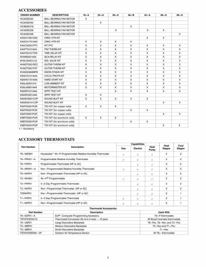
ACCESSORIESORDER NUMBER DESCRIPTION 18---A 24---A 30---A 36---B 42---A 48---A 60---A
HC32GE234 BALL BEARING FAN MOTOR X
HC34GE240 BALL BEARING FAN MOTOR X
HC38GE219 BALL BEARING FAN MOTOR X
HC40GE226 BALL BEARING FAN MOTOR X X X
HC40GE228 BALL BEARING FAN MOTOR X
KAACH1601AAA CRKC HTR KIT X X
KAACH1701AAA CRKC HTR KIT X X X X
KAACS0201PTC KIT PTC X X X X X X X
KAAFT0101AAA FRZ THERM KIT X X X X X X X
KAATD0101TDR TIME DELAY KIT X X X X X X X
KHAIR0201AAA ISLN RELAY KIT X X X X X X X
KHALS0401LLS SOL VALVE KIT X X X X X X X
KHAOT0201SEC OUTDR THERM KIT X X X X X X X
KHAOT0301FST OUTDR THERM KIT X X X X X X X
KHASS0606MPK SNOW STAND KIT X X X X X X X
KSACY0101AAA CYCLE PROTR KIT X X X X X X X
KSAHS1701AAA HARD START KIT X X X X X X X
KSALA0301410 LOW AMBIENT KIT X X X X X X X
KSALA0601AAA MOTORMASTER KIT X X X X X X X
KSASF0101AAA SPRT FEET KIT X X X X X
KSASF0201AAA SPRT FEET KIT X X
KSASH0601COP SOUND BLKT KIT X X X X X
KSASH2101COP SOUND BLKT KIT X X
KSATX0201PUR TXV KIT (for copper coils) X X X
KSATX0301PUR TXV KIT (for copper coils) X X
KSATX0501PUR TXV KIT (for copper coils) X X
KSBTX0201PUR TXV KIT (for aluminum coils) X X X
KSBTX0301PUR TXV KIT (for aluminum coils) X X
KSBTX0401PUR TXV KIT (for aluminum coils) X Xx = Accessory
ACCESSORY THERMOSTATS
Part Number DescriptionCapabilities
HeatStages
CoolStagesGas Electric Heat
Pump
T6---WEM01 Housewise™ Wi---Fi Programmable Relative Humidity Thermostat √ √ √ 4 2
T6---PRH01---A Programmable Relative Humidity Thermostat √ √ √ 3 2
T6---PHP01 Programmable Thermostat (HP or AC) √ √ 3 2
T6---NRH01---A Non---Programmable Relative Humidity Thermostat √ √ √ 3 2
T6---NHP01 Non---Programmable Thermostat (HP or AC) √ √ 3 2
T2---WHS01 Wi---Fi® Programmable √ √ √ 3 2
T2---PHP01 5---2 Day Programmable Thermostat √ √ 3 2
T2---NHP01 Non---Programmale Thermostat (HP or AC) √ √ 3 2
T2SNHP01 Non---Programmable Thermostat (HP or AC) √ √ 2 1
T1---PHP01 5---2 Day Programmable Thermostat √ √ √ 2 1
T1---NHP01 Non---Programmable Thermostat (HP or AC) √ √ √ 2 1
Thermostat Accessories
Part Number Description Used WithT6---EXP01---A ExP Computer Programming Accessory T6---P thermostatsTSTATXXCNV10 Thermostat Conversion Kit (4 to 5 wire) --- 10 pack All Bryant branded thermostatsTX---LBP01 Large Decorative Backplate T6---Pxx, T6---Nxx, and T2---PxxTX---MBP01 Medium Decorative Backplate T2---Nxx and T1---PxxTX---SBP01 Small Decorative Backplate T1---NxxTSTATXXSEN01---B* Outdoor Air Temperature Sensor All T6--- thermostats

6
ACCESSORY USAGE GUIDELINE
AccessoryREQUIRED FOR LOW---AMBIENTCOOLING APPLICATIONS(Below 55F / 12.8C)
REQUIRED FORLONG LINE APPLICATIONS*
REQUIRED FORSEA COAST APPLICATIONS(Within 2 miles / 3.22 km)
Accumulator Standard Standard StandardBall Bearing Fan Motor Yes{ No No
Compressor Start Assist Capacitor andRelay Yes Yes No
Crankcase Heater Yes Yes No
Evaporator Freeze Thermostat Yes No NoHard Shutoff TXV Yes Yes NoIsolation Relay Yes No No
Liquid Line Solenoid Valve No See Long---Line Application Guideline NoMotor Master Control orLow Ambient Switch Yes No No
Support Feet Recommended No Recommended
* For tubing line sets between 80 and 200 ft. (24.38 and 60.96 m) and/or 20 ft. (6.09 m) vertical differential, refer to Residential Split ---System LonglineApplication Guideline.
{ Additional requirement for Low---Ambient Controller (full modulation feature) MotorMasterr Control.
Accessory Description and Usage (Listed Alphabetically)1. Ball--Bearing Fan MotorA fan motor with ball bearings which permits speed reductionwhile maintaining bearing lubrication.
Usage Guideline:Required on all units when using MotorMasterr
2. Compressor Start Assist -- Capacitor and RelayStart capacitor and relay gives a hard boost to compressor motor ateach start up.
Usage Guideline:Required for reciprocating compressors in the followingapplications:
Long lineLow ambient coolingHard shut off expansion valve on indoor coilLiquid line solenoid on indoor coil
Required for single--phase scroll compressors in thefollowing applications:
Long lineLow ambient cooling
Suggested for all compressors in areas with a history oflow voltage problems.3. Compressor Start Assist — PTC TypeSolid state electrical device which gives a soft boost to thecompressor at each start--up.
Usage Guideline:Suggested in installations with marginal power supply.
4. Crankcase HeaterAn electric resistance heater which mounts to the base of thecompressor to keep the lubricant warm during off cycles. Improvescompressor lubrication on restart and minimizes the chance ofliquid slugging.
Usage Guideline:Required in low ambient cooling applications.Required in long line applications.Suggested in all commercial applications.
5. Evaporator Freeze ThermostatAn SPST temperature--actuated switch that stops unit operationwhen evaporator reaches freeze--up conditions.
Usage Guideline:Required when low ambient kit has been added.
6. Isolation RelayAn SPDT relay which switches the low--ambient controller out ofthe outdoor fan motor circuit when the heat pump switches toheating mode.
Usage Guideline:Required in all heat pumps where low ambient kit hasbeen added.
7. Liquid--Line Solenoid Valve (LLS)An electrically operated shutoff valve which stops and startsrefrigerant liquid flow in response to compressor operation. It is tobe installed at the outdoor unit to control refrigerant off cyclemigration in the heating mode.
Usage Guideline:An LLS is required in all long line heat pumpapplications to control refrigerant off cycle migration inthe heating mode. See Long Line Guideline.
8. Low--Ambient Pressure Switch KitA long life pressure switch which is mounted to outdoor unitservice valve. It is designed to cycle the outdoor fan motor in orderto maintain head pressure within normal operating limits. Thecontrol will maintain working head pressure at low--ambienttemperatures down to 0_F (--18_C) when properly installed.
Usage Guideline:A Low--Ambient Pressure Switch or MotorMasterrLow--Ambient Controller must be used when coolingoperation is used at outdoor temperatures below 55_F(12.8_C).
9. MotorMasterr Low--Ambient ControllerA fan--speed control device activated by a temperature sensor,designed to control condenser fan motor speed in response to thesaturated, condensing temperature during operation in coolingmode only. For outdoor temperatures down to --20_F (--28.9_C), itmaintains condensing temperature at 100_F 10_F (37.8_C 6.5_C).
Usage Guideline:A MotorMasterr Low Ambient Controller orLow--Ambient Pressure Switch must be used whencooling operation is used at outdoor temperaturesbelow 55_F (12.8_C).
Suggested for all commercial applications.

7
Accessory Description and Usage (Listed Alphabetically) -- CONTINUED
10. Outdoor Air Temperature SensorDesigned for use with Bryant Thermostats listed in thispublication. This device enables the thermostat to display theoutdoor temperature. This device also is required to enable specialthermostat features such as auxiliary heat lock out.
Usage Guideline:Suggested for all Bryant thermostats listed in thispublication.
11. Outdoor ThermostatAn SPDT temperature--actuated switch which turns onsupplemental electric heaters when outdoor air temperature dropsbelow a user--selected set point.
Usage Guideline:Electric supplemental heat applications in non--variablespeed indoor units when electric heat staging is desired.
12. Secondary Outdoor ThermostatAn SPDT temperature--actuated switch which turns on third--stageof supplemental electric heaters when outdoor air temperaturedrops below the second--stage set point.
Usage Guideline:Outdoor thermostat applications where electric heater iscapable of 3--stage operation.
13. Snow Stand RackCoated wire rack which supports unit 18 in. (457.2 mm) abovemounting pad to allow for drainage from unit base.
Usage Guideline:Suggested in the following applications:
Heat pump installations in heavy snowfall areas.Heat pump installations in snow drift locations.Heat pump installations in areas of prolongedsubfreezing temperatures.All commercial installations.
14. Sound HoodWraparound sound reducing cover for the compressor. Reduces thesound level by about 2 dBA.
Usage Guideline:Suggested when unit is installed closer than 15 ft.(4.577 m) to quiet areas, bedrooms, etc.Suggested when unit is installed between two houses lessthan 10 ft. (3.05 m) apart.
15. Thermostatic Expansion Valve (TXV) Bi--FlowA modulating flow--control valve which meters refrigerant liquidflow rate into the evaporator in response to the superheat of therefrigerant gas leaving the evaporator.
Usage Guideline:Accessory required to meet AHRI rating and systemreliability, where indoor not equipped.Required in all heat pump applications designed withPuron refrigerant.
16. Time--Delay RelayAn SPST delay relay which briefly continues operation of indoorblower motor to provide additional cooling after the compressorcycles off.Note:Most indoor unit controls include this feature. For those thatdo not, use the guideline below.
Usage Guideline:Accessory required to meet AHRI rating, where indoornot equipped.

8
ELECTRICAL DATA
UNIT SIZE V/PHOPER VOLTS* COMPR FAN
MCA
MAXFUSE** orCKT BRKAMPSMAX MIN LRA RLA FLA
18
208/230/1 253 197
48.0 9.0 0.50 11.8 2024 62.9 10.9 0.60 14.2 2530 72.5 13.5 1.40 18.3 3036 75.0 14.7 1.10 19.5 3042 105.5 15.5 1.40 24.0 4048 108.0 19.0 1.40 25.2 4060 144.2 24.4 1.52 32.0 50
* Permissible limits of the voltage range at which the unit will operate satisfactorily** Time---Delay fuse.FLA --- Full Load AmpsLRA --- Locked Rotor AmpsMCA --- Minimum Circuit AmpsRLA --- Rated Load AmpsNOTE: Control circuit is 24---V on all units and requires external power source. Copper wire must be used from service disconnect to unit.All motors/compressors contain internal overload protection.Complies with 2007 requirements of ASHRAE Standards 90.1
A--WEIGHTED SOUND POWER
UNIT SIZESTANDARDRATING(dBA)
TYPICAL OCTAVE BAND SPECTRUM (dBA, without tone adjustment)
125 250 500 1000 2000 4000 8000
18 69 45 48 56 62 55 53 4724 76 46 56 59 63 63 60 5530 77 52 62 67 68 65 62 5536 77 51 62 66 69 64 61 5342 76 49 61 63 65 62 60 5248 79 53 66 69 71 67 64 5760 73 50 63 62 63 60 58 52
NOTE: Tested in accordance with AHRI Standard 270---08 (not listed in AHRI).
A--WEIGHTED SOUND POWERWITH SOUND HOOD
UNIT SIZE STANDARDRATING
TYPICAL OCTAVE BAND SPECTRUM (dBA, without tone adjustment)125 250 500 1000 2000 4000 8000
18 68 47 48 56 61 55 52 4624 74 47 57 59 62 61 58 5130 77 52 62 67 67 65 62 5436 76 52 62 66 67 64 60 5242 74 50 61 63 64 61 58 4948 79 54 66 69 70 67 64 5660 73 51 64 62 63 59 56 49
NOTE: Tested in accordance with AHRI Standard 270---08 (not listed in AHRI).
CHARGING SUBCOOLING (TXV--TYPE EXPANSION DEVICE)UNIT SIZE---SERIES REQUIRED SUBCOOLING ° F (° C)
18 11 (6.1)24 11 (6.1)30 10 (5.6)36 10 (5.6)42 10 (5.6)48 14 (7.8)60 15 (8.3)
HP ONLY REPLACEMENTWITH PISTON INDOORSWhen the 214D is used as a replacement component in a system with a piston fan coil, use the indoor piston size specified below:
UNIT SIZEPISTON SIZE
FB4CNF FFM FPMA18 0.052 0.050 0.05024 0.057 0.057 0.05630 0.067 0.070 0.06736 0.070 0.072 0.06942 0.07848 0.08460
= N/A
9
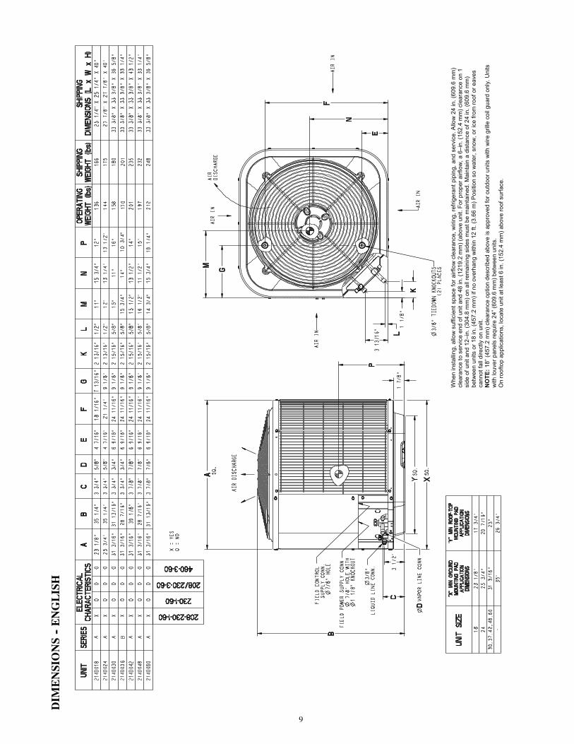
DIM
ENSIONS--ENGLISH
Whe
n in
stal
ling,
allo
w s
uffic
ient
spa
ce fo
r airf
low
cle
aran
ce, w
iring
, ref
riger
ant p
ipin
g, a
nd s
ervi
ce. A
llow
24
in. (
609.
6 m
m)
clea
ranc
e to
ser
vice
end
of u
nit a
nd 4
8 in
. (12
19.2
mm
) (ab
ove
unit.
For
pro
per a
irflo
w, a
6–i
n. (1
52.4
mm
) cle
aran
ce o
n 1
side
of u
nit a
nd 1
2–in
. (30
4.8
mm
) on
all r
emai
ning
sid
es m
ust b
e m
aint
aine
d. M
aint
ain
a di
stan
ce o
f 24
in. (
609.
6 m
m)
betw
een
units
or 1
8 in
. (45
7.2
mm
) if n
o ov
erha
ng w
ithin
12
ft. (3
.66
m) P
ositi
on s
o w
ater
, sno
w, o
r ice
from
roof
or e
aves
ca
nnot
fall
dire
ctly
on
unit.
N
OTE
: 18”
(457
.2 m
m) c
lear
ance
opt
ion
desc
ribed
abo
ve is
app
rove
d fo
r out
door
uni
ts w
ith w
ire g
rille
coi
l gua
rd o
nly.
Uni
ts
with
louv
er p
anel
s re
quire
24”
(609
.6 m
m) b
etw
een
units
. O
n ro
ofto
p ap
plic
atio
ns, l
ocat
e un
it at
leas
t 6 in
. (15
2.4
mm
) abo
ve ro
of s
urfa
ce.

10
DIM
ENSIONS--SI
Whe
n in
stal
ling,
allo
w s
uffic
ient
spa
ce fo
r airf
low
cle
aran
ce, w
iring
, ref
riger
ant p
ipin
g, a
nd s
ervi
ce. A
llow
24
in. (
609.
6 m
m)
clea
ranc
e to
ser
vice
end
of u
nit a
nd 4
8 in
. (12
19.2
mm
) (ab
ove
unit.
For
pro
per a
irflo
w, a
6–i
n. (1
52.4
mm
) cle
aran
ce o
n 1
side
of u
nit a
nd 1
2–in
. (30
4.8
mm
) on
all r
emai
ning
sid
es m
ust b
e m
aint
aine
d. M
aint
ain
a di
stan
ce o
f 24
in. (
609.
6 m
m)
betw
een
units
or 1
8 in
. (45
7.2
mm
) if n
o ov
erha
ng w
ithin
12
ft. (3
.66
m) P
ositi
on s
o w
ater
, sno
w, o
r ice
from
roof
or e
aves
ca
nnot
fall
dire
ctly
on
unit.
N
OTE
: 18”
(457
.2 m
m) c
lear
ance
opt
ion
desc
ribed
abo
ve is
app
rove
d fo
r out
door
uni
ts w
ith w
ire g
rille
coi
l gua
rd o
nly.
Uni
ts
with
louv
er p
anel
s re
quire
24”
(609
.6 m
m) b
etw
een
units
. O
n ro
ofto
p ap
plic
atio
ns, l
ocat
e un
it at
leas
t 6 in
. (15
2.4
mm
) abo
ve ro
of s
urfa
ce.

11
CLEARANCES
Cle
aran
ces
(var
iou
s ex
amp
les)
Wal
l6”
(1
52.4
)
24”
(609
.6)
Ser
vice
Wal
l
Wal
l
Wall
12”
(304
.8)
12”
(304
.8)
18”
(457
.2)
24”
(609
.6)
Ser
vice
6”
(152
.4)
12”
(304
.8)
24”
(609
.6)
Ser
vice
24”
(609
.6)
Ser
vice
24”
(609
.6)
Ser
vice
No
te:
Nu
mb
ers
in (
) =
mm
18”
(457
.2)
18”
(457
.2)
12”
(304
.8)
IMPORTA
NT:Wheninstallingmultipleunitsinan
alcove,roofwell,orpartially
enclosed
area,ensurethereisadequateventilationtopreventre--circulationofdischargeair.

12
BALANCEPOINTWORKSH
EET
0.0
2.9
5.9
8.8
11.7
14.6
17.6
20.5
23.4
01020304050607080
kW
BUILDING HEAT LOSS, UNIT INTEGRATED HEATING CAPACITY, MBTUH
214D
NA
018
FB4C
NP
018L
214D
NA
024
FB4C
NP
030L
214D
NA
042
FB4C
NP0
42L
214D
NA
030
FB4C
NP
030L
214D
NA
048
FB4C
NP0
48L
214D
NA
060
FX4D
NF0
61L
214D
NA
036
FB4C
NP
036L
-23.
3-1
7.8
-12.
2-6
.7-1
.14.
410
.015
.621
.126
.7
-10.
00.
010
.020
.030
.040
.050
.060
.070
.080
.0
OUTD
OOR
TEM
PERA
TURE
0 F 0 C
BA
SE
D O
N IN
DO
OR
EN
TER
ING
AIR
AT
70◦
F (2
1.1◦
C) A
ND
AT
RAT
ED
CFM

13
TESTED AHRI COMBINATION RATINGS
NOTE: Ratings contained in this document are subject to change at any time.For AHRI ratings certificates, please refer to the AHRI directory www.ahridirectory.orgAdditional ratings and system combinations can be accessed via the Bryant database at: www.MyBryantRatings.comFor performance data at specific application &/or design conditions with various indoor unit combinations, theequipment performance calculator can be accessed at : http://rpmobbry.wrightsoft.com/
Model Number Indoor Coil ModelNumber
CoolingCapacity EER SEER
High TempHSPF
Low Temp
ECapacity E COP H
Capacity H COP
214DNA018---A FB4CNP018L 17,800 11.7 14 17,600 3.72 8.2 10,400 2.40
214DNA024---A FB4CNP030L 22,200 11.5 14 22,200 3.84 8.2 13,200 2.54
214DNA030---A FB4CNP030L 28,600 11.7 14 28,600 3.62 8.2 17,100 2.44
214DNA036---B FB4CNP036L 33,000 11.7 14 33,800 3.62 8.2 21,000 2.40
214DNA042---A FB4CNP042L 40,000 11.5 14 41,000 3.62 8.2 25,200 2.50
214DNA048---A FB4CNP048L 46,000 11.7 14 45,500 3.64 8.2 27,800 2.56
214DNA060---A FX4DN(B,F)061L 57,000 11.7 14 54,500 3.70 8.2 33,000 2.56
* AHRI = Air Conditioning, Heating & Refrigeration Institute* Ratings are net values reflecting the effects of circulating fan heat. Supplemental electric heat is not included. Ratings are based on:Cooling Standard: 80_F (27_C) db 67_F (19_C) wb indoor entering air temperature and 95_F (35_C) db air entering outdoor unit.High---Temp Heating Standard: 70_F (21_C) db indoor entering air temperature and 47_F (8_C) db 43° F (6_C) wb air entering outdoor unit.Low---Temp Heating Standard: 70_F (21_C) db indoor entering air temperature and 17_F (---8_C) db 15° F (---9_C) wb air entering outdoor unit.COP— Coefficient of PerformanceEER— Energy Efficiency RatioHSPF— Heating Seasonal Performance FactorSEER— Seasonal Energy Efficiency Ratio

14
DETA
ILEDCOOLINGCAPA
CITIES#
EVAPORATORAIR
CONDENSERENTERINGAIRTEMPERATURES°F(°C)
75(23.9)
85(29.4)
95(35)
105(40.6)
115(46.1)
125(51.7)
CFM
EWB
°F(°C)
CapacityMBtuh
Total
System
KW**
CapacityMBtuh
Total
System
KW**
CapacityMBtuh
Total
System
KW**
CapacityMBtuh
Total
System
KW**
CapacityMBtuh
Total
System
KW**
CapacityMBtuh
Total
System
KW**
Total
Sens‡
Total
Sens‡
Total
Sens‡
Total
Sens‡
Total
Sens‡
Total
Sens‡
214DNA018OutdoorSectionWithFB4CNP018LIndoorSection
525
72(22.2)
21.43
10.44
1.20
20.38
10.06
1.36
19.27
9.66
1.54
18.10
9.26
1.74
16.86
8.83
1.97
15.56
8.39
2.22
67(19.4)
19.44
12.77
1.19
18.48
12.39
1.36
17.47
11.99
1.53
16.40
11.58
1.73
15.26
11.15
1.96
14.06
10.69
2.21
63(17.2)††
17.99
12.27
1.19
17.10
11.90
1.35
16.16
11.50
1.53
15.16
11.08
1.73
14.10
10.65
1.95
12.98
10.19
2.20
62(16.7)
17.64
15.03
1.19
16.78
14.64
1.35
15.88
14.22
1.53
14.93
13.76
1.73
14.00
14.00
1.95
13.10
13.10
2.20
57(13.9)
16.97
16.97
1.19
16.30
16.30
1.35
15.58
15.58
1.52
14.81
14.81
1.73
13.98
13.98
1.95
13.08
13.08
2.20
600
72(22.2)
21.88
10.96
1.21
20.77
10.58
1.38
19.62
10.18
1.56
18.40
9.76
1.76
17.12
9.33
1.98
15.77
8.88
2.23
67(19.4)
19.86
13.61
1.20
18.86
13.22
1.37
17.80
12.82
1.55
16.69
12.39
1.75
15.51
11.95
1.97
14.27
11.48
2.22
63(17.2)††
18.40
13.06
1.20
17.47
12.67
1.36
16.49
12.27
1.54
15.44
11.84
1.74
14.34
11.39
1.97
13.19
10.92
2.21
62(16.7)
18.08
16.13
1.20
17.20
15.71
1.36
16.27
16.27
1.54
15.43
15.43
1.74
14.54
14.54
1.97
13.59
13.59
2.22
57(13.9)
17.73
17.73
1.20
17.01
17.01
1.36
16.24
16.24
1.54
15.41
15.41
1.74
14.52
14.52
1.97
13.57
13.57
2.22
675
72(22.2)
22.22
11.46
1.22
21.08
11.07
1.39
19.88
10.66
1.57
18.63
10.24
1.77
17.31
9.80
2.00
15.92
9.35
2.25
67(19.4)
20.19
14.41
1.22
19.15
14.01
1.38
18.06
13.60
1.56
16.91
13.16
1.76
15.70
12.71
1.99
14.44
12.22
2.23
63(17.2)††
18.71
13.81
1.21
17.75
13.41
1.38
16.74
12.99
1.56
15.66
12.55
1.75
14.53
12.09
1.98
13.35
11.59
2.23
62(16.7)
18.48
17.11
1.21
17.63
17.63
1.38
16.80
16.80
1.56
15.93
15.93
1.76
14.99
14.99
1.98
13.99
13.99
2.23
57(13.9)
18.36
18.36
1.21
17.60
17.60
1.38
16.78
16.78
1.56
15.91
15.91
1.75
14.97
14.97
1.98
13.97
13.97
2.23
EVAPORATORAIR
CONDENSERENTERINGAIRTEMPERATURES°F(°C)
75(23.9)
85(29.4)
95(35)
105(40.6)
115(46.1)
125(51.7)
CFM
EWB
°F(°C)
CapacityMBtuh
Total
System
KW**
CapacityMBtuh
Total
System
KW**
CapacityMBtuh
Total
System
KW**
CapacityMBtuh
Total
System
KW**
CapacityMBtuh
Total
System
KW**
CapacityMBtuh
Total
System
KW**
Total
Sens‡
Total
Sens‡
Total
Sens‡
Total
Sens‡
Total
Sens‡
Total
Sens‡
214DNA024OutdoorSectionWithFB4CNP030LIndoorSection
700
72(22.2)
26.47
13.51
1.53
25.28
13.08
1.71
24.03
12.62
1.91
22.72
12.15
2.14
21.30
11.65
2.41
19.77
11.11
2.72
67(19.4)
24.06
16.68
1.53
22.96
16.24
1.71
21.82
15.78
1.91
20.62
15.31
2.15
19.33
14.80
2.42
17.93
14.25
2.72
63(17.2)††
22.32
16.04
1.53
21.30
15.60
1.72
20.23
15.14
1.92
19.11
14.66
2.16
17.91
14.15
2.42
16.62
13.60
2.73
62(16.7)
21.92
19.75
1.53
20.94
19.28
1.72
19.93
18.78
1.92
18.88
18.78
2.16
17.88
17.88
2.42
16.83
16.83
2.73
57(13.9)
21.31
21.31
1.54
20.52
20.52
1.72
19.70
19.70
1.92
18.81
18.81
2.16
17.86
17.86
2.42
16.81
16.81
2.73
800
72(22.2)
26.97
14.20
1.55
25.73
13.76
1.72
24.44
13.30
1.92
23.07
12.82
2.16
21.60
12.31
2.43
20.01
11.76
2.74
67(19.4)
24.53
17.79
1.55
23.38
17.34
1.73
22.20
16.87
1.93
20.95
16.38
2.16
19.61
15.86
2.43
18.18
15.29
2.74
63(17.2)††
22.77
17.07
1.55
21.70
16.62
1.73
20.60
16.15
1.94
19.43
15.65
2.17
18.19
15.13
2.44
16.86
14.56
2.75
62(16.7)
22.45
21.17
1.55
21.45
21.27
1.73
20.50
20.50
1.94
19.55
19.55
2.17
18.53
18.53
2.44
17.41
17.41
2.74
57(13.9)
22.20
22.20
1.55
21.35
21.35
1.73
20.47
20.47
1.94
19.53
19.53
2.17
18.51
18.51
2.44
17.39
17.39
2.74
900
72(22.2)
27.35
14.86
1.56
26.08
14.41
1.74
24.73
13.94
1.94
23.33
13.46
2.17
21.82
12.94
2.44
20.18
12.38
2.75
67(19.4)
24.89
18.85
1.57
23.71
18.38
1.75
22.49
17.91
1.95
21.20
17.40
2.18
19.84
16.86
2.45
18.37
16.26
2.76
63(17.2)††
23.12
18.05
1.57
22.02
17.59
1.75
20.88
17.10
1.96
19.68
16.59
2.19
18.41
16.05
2.46
17.05
15.45
2.77
62(16.7)
22.97
22.97
1.57
22.08
22.08
1.75
21.14
21.14
1.95
20.14
20.14
2.19
19.07
19.07
2.45
17.88
17.88
2.76
57(13.9)
22.94
22.94
1.57
22.05
22.05
1.75
21.11
21.11
1.95
20.12
20.12
2.19
19.04
19.04
2.45
17.86
17.86
2.76
EVAPORATORAIR
CONDENSERENTERINGAIRTEMPERATURES°F(°C)
75(23.9)
85(29.4)
95(35)
105(40.6)
115(46.1)
125(51.7)
CFM
EWB
°F(°C)
CapacityMBtuh
Total
System
KW**
CapacityMBtuh
Total
System
KW**
CapacityMBtuh
Total
System
KW**
CapacityMBtuh
Total
System
KW**
CapacityMBtuh
Total
System
KW**
CapacityMBtuh
Total
System
KW**
Total
Sens‡
Total
Sens‡
Total
Sens‡
Total
Sens‡
Total
Sens‡
Total
Sens‡
214DNA030OutdoorSectionWithFB4CNP030LIndoorSection
875
72(22.2)
33.97
17.32
1.97
32.47
16.75
2.17
30.87
16.16
2.40
29.15
15.54
2.67
27.30
14.87
2.98
25.29
14.15
3.33
67(19.4)
30.80
21.30
1.97
29.42
20.72
2.17
27.96
20.13
2.40
26.39
19.50
2.67
24.69
18.82
2.98
22.86
18.10
3.32
63(17.2)††
28.51
20.46
1.97
27.22
19.89
2.17
25.86
19.29
2.41
24.39
18.66
2.67
22.82
17.98
2.97
21.12
17.25
3.32
62(16.7)
27.99
25.15
1.97
26.74
24.55
2.17
25.44
23.90
2.41
24.07
23.17
2.67
22.67
22.67
2.97
21.30
21.30
3.32
57(13.9)
27.05
27.05
1.97
26.06
26.06
2.18
25.01
25.01
2.41
23.88
23.88
2.67
22.64
22.64
2.97
21.27
21.27
3.32
1050
72(22.2)
34.85
18.48
2.00
33.25
17.90
2.21
31.57
17.30
2.44
29.76
16.66
2.71
27.81
15.97
3.02
25.71
15.24
3.37
67(19.4)
31.61
23.17
2.01
30.15
22.59
2.21
28.60
21.97
2.44
26.95
21.32
2.71
25.18
20.61
3.02
23.27
19.84
3.36
63(17.2)††
29.28
22.21
2.01
27.91
21.62
2.21
26.47
21.00
2.45
24.94
20.34
2.71
23.29
19.63
3.01
21.52
18.86
3.36
62(16.7)
28.88
27.53
2.01
27.62
27.37
2.21
26.36
26.36
2.45
25.12
25.12
2.71
23.77
23.77
3.01
22.28
22.28
3.36
57(13.9)
28.55
28.55
2.01
27.48
27.48
2.21
26.33
26.33
2.45
25.09
25.09
2.71
23.74
23.74
3.01
22.26
22.26
3.36
1125
72(22.2)
35.15
18.97
2.02
33.53
18.39
2.23
31.81
17.78
2.46
29.96
17.13
2.73
27.99
16.44
3.03
25.85
15.70
3.38
67(19.4)
31.89
23.96
2.02
30.39
23.37
2.23
28.82
22.74
2.46
27.14
22.07
2.73
25.34
21.35
3.03
23.41
20.56
3.38
63(17.2)††
29.55
22.94
2.03
28.15
22.34
2.23
26.69
21.71
2.46
25.12
21.03
2.73
23.45
20.30
3.03
21.66
19.51
3.38
62(16.7)
29.18
29.18
2.03
28.02
28.02
2.23
26.83
26.83
2.46
25.55
25.55
2.73
24.15
24.15
3.03
22.63
22.63
3.38
57(13.9)
29.10
29.10
2.03
27.98
27.98
2.23
26.80
26.80
2.46
25.52
25.52
2.73
24.13
24.13
3.03
22.60
22.60
3.38
Seenotesonpage16

15
DETA
ILEDCOOLINGCAPA
CITIES#CONTINUED
EVAPORATORAIR
CONDENSERENTERINGAIRTEMPERATURES°F(°C)
75(23.9)
85(29.4)
95(35)
105(40.6)
115(46.1)
125(51.7)
CFM
EWB
°F(°C)
CapacityMBtuh
Total
System
KW**
CapacityMBtuh
Total
System
KW**
CapacityMBtuh
Total
System
KW**
CapacityMBtuh
Total
System
KW**
CapacityMBtuh
Total
System
KW**
CapacityMBtuh
Total
System
KW**
Total
Sens‡
Total
Sens‡
Total
Sens‡
Total
Sens‡
Total
Sens‡
Total
Sens‡
214DNA036OutdoorSectionWithFB4CNP036LIndoorSection
1050
72(22.2)
39.42
20.36
2.23
37.61
19.67
2.50
35.70
18.96
2.79
33.63
18.20
3.10
31.37
17.37
3.46
28.97
16.51
3.85
67(19.4)
35.87
25.19
2.24
34.23
24.50
2.50
32.48
23.78
2.78
30.59
23.01
3.09
28.52
22.17
3.44
26.33
21.29
3.84
63(17.2)††
33.28
24.23
2.25
31.76
23.54
2.50
30.14
22.82
2.77
28.38
22.05
3.08
26.45
21.21
3.43
24.41
20.32
3.84
62(16.7)
32.68
29.85
2.25
31.22
29.12
2.50
29.67
28.32
2.77
28.03
27.40
3.08
26.31
26.31
3.43
24.65
24.65
3.84
57(13.9)
31.63
31.63
2.26
30.46
30.46
2.50
29.20
29.20
2.77
27.82
27.82
3.08
26.28
26.28
3.43
24.62
24.62
3.84
1200
72(22.2)
40.13
21.34
2.27
38.25
20.63
2.54
36.25
19.90
2.83
34.10
19.12
3.14
31.76
18.28
3.50
29.28
17.40
3.90
67(19.4)
36.53
26.77
2.28
34.82
26.07
2.54
33.00
25.34
2.82
31.03
24.54
3.13
28.88
23.67
3.49
26.62
22.75
3.89
63(17.2)††
33.92
25.70
2.29
32.33
25.00
2.54
30.64
24.26
2.82
28.81
23.47
3.13
26.81
22.59
3.48
24.71
21.66
3.88
62(16.7)
33.39
31.85
2.29
31.89
31.02
2.54
30.31
30.31
2.82
28.80
28.80
3.12
27.16
27.16
3.48
25.40
25.40
3.88
57(13.9)
32.83
32.83
2.29
31.58
31.58
2.54
30.24
30.24
2.82
28.77
28.77
3.12
27.13
27.13
3.48
25.37
25.37
3.88
1350
72(22.2)
40.68
22.25
2.31
38.72
21.53
2.58
36.66
20.80
2.87
34.45
20.01
3.19
32.03
19.15
3.54
29.50
18.26
3.94
67(19.4)
37.04
28.29
2.32
35.25
27.57
2.58
33.37
26.81
2.86
31.35
25.98
3.17
29.14
25.07
3.53
26.85
24.10
3.93
63(17.2)††
34.40
27.11
2.33
32.75
26.38
2.58
31.00
25.62
2.86
29.12
24.79
3.17
27.07
23.87
3.52
24.93
22.89
3.92
62(16.7)
33.95
33.95
2.33
32.55
32.55
2.58
31.13
31.13
2.86
29.57
29.57
3.17
27.85
27.85
3.52
26.00
26.00
3.93
57(13.9)
33.84
33.84
2.33
32.51
32.51
2.58
31.10
31.10
2.86
29.54
29.54
3.17
27.82
27.82
3.52
25.98
25.98
3.93
EVAPORATORAIR
CONDENSERENTERINGAIRTEMPERATURES°F(°C)
75(23.9)
85(29.4)
95(35)
105(40.6)
115(46.1)
125(51.7)
CFM
EWB
°F(°C)
CapacityMBtuh
Total
System
KW**
CapacityMBtuh
Total
System
KW**
CapacityMBtuh
Total
System
KW**
CapacityMBtuh
Total
System
KW**
CapacityMBtuh
Total
System
KW**
CapacityMBtuh
Total
System
KW**
Total
Sens‡
Total
Sens‡
Total
Sens‡
Total
Sens‡
Total
Sens‡
Total
Sens‡
214DNA042OutdoorSectionWithFB4CNP042LIndoorSection
1225
72(22.2)
48.18
24.31
2.78
46.14
23.54
3.12
43.91
22.72
3.47
41.39
21.79
3.89
38.48
20.75
4.38
35.14
19.57
4.98
67(19.4)
43.90
29.85
2.81
42.03
29.07
3.13
40.00
28.24
3.48
37.70
27.31
3.88
35.04
26.26
4.38
31.98
25.05
5.00
63(17.2)††
40.78
28.76
2.83
39.02
27.98
3.14
37.15
27.15
3.48
35.01
26.22
3.88
32.54
25.16
4.38
29.68
23.95
5.01
62(16.7)
40.02
35.22
2.83
38.32
34.41
3.14
36.51
33.54
3.48
34.48
32.52
3.88
32.15
32.15
4.38
29.82
29.82
5.01
57(13.9)
38.47
38.47
2.84
37.12
37.12
3.14
35.68
35.68
3.48
34.03
34.03
3.88
32.08
32.08
4.38
29.78
29.78
5.01
1400
72(22.2)
49.11
25.48
2.81
46.98
24.70
3.15
44.64
23.85
3.51
42.03
22.91
3.92
39.00
21.85
4.41
35.57
20.66
5.02
67(19.4)
44.77
31.73
2.84
42.82
30.94
3.17
40.70
30.10
3.51
38.30
29.14
3.92
35.55
28.06
4.42
32.39
26.81
5.03
63(17.2)††
41.63
30.52
2.86
39.80
29.72
3.17
37.83
28.87
3.52
35.61
27.92
3.92
33.04
26.83
4.42
30.10
25.58
5.04
62(16.7)
40.95
37.70
2.86
39.20
36.82
3.18
37.36
35.82
3.52
35.36
35.36
3.92
33.27
33.27
4.42
30.82
30.82
5.04
57(13.9)
40.07
40.07
2.87
38.63
38.63
3.18
37.09
37.09
3.52
35.31
35.31
3.92
33.23
33.23
4.42
30.78
30.78
5.04
1575
72(22.2)
49.81
26.57
2.84
47.60
25.78
3.18
45.20
24.93
3.54
42.49
23.97
3.96
39.38
22.90
4.44
35.86
21.70
5.05
67(19.4)
45.44
33.53
2.87
43.41
32.72
3.20
41.22
31.85
3.55
38.75
30.88
3.96
35.92
29.75
4.45
32.71
28.46
5.06
63(17.2)††
42.28
32.19
2.89
40.38
31.38
3.21
38.36
30.51
3.55
36.06
29.53
3.96
33.43
28.40
4.45
30.42
27.09
5.08
62(16.7)
41.76
39.89
2.89
39.97
39.97
3.21
38.30
38.30
3.55
36.41
36.41
3.96
34.21
34.21
4.45
31.64
31.64
5.07
57(13.9)
41.40
41.40
2.90
39.89
39.89
3.21
38.25
38.25
3.55
36.36
36.36
3.96
34.17
34.17
4.45
31.60
31.60
5.07
EVAPORATORAIR
CONDENSERENTERINGAIRTEMPERATURES°F(°C)
75(23.9)
85(29.4)
95(35)
105(40.6)
115(46.1)
125(51.7)
CFM
EWB
°F(°C)
CapacityMBtuh
Total
System
KW**
CapacityMBtuh
Total
System
KW**
CapacityMBtuh
Total
System
KW**
CapacityMBtuh
Total
System
KW**
CapacityMBtuh
Total
System
KW**
CapacityMBtuh
Total
System
KW**
Total
Sens‡
Total
Sens‡
Total
Sens‡
Total
Sens‡
Total
Sens‡
Total
Sens‡
214DNA048OutdoorSectionWithFB4CNP048LIndoorSection
1400
72(22.2)
55.75
28.05
3.23
53.27
27.12
3.59
50.55
26.11
3.96
47.46
24.99
4.37
44.01
23.75
4.83
40.13
22.38
5.35
67(19.4)
50.68
34.45
3.22
48.45
33.53
3.57
46.00
32.52
3.93
43.23
31.42
4.34
40.10
30.17
4.80
36.59
28.79
5.33
63(17.2)††
46.99
33.15
3.22
44.92
32.23
3.55
42.67
31.23
3.91
40.12
30.14
4.31
37.25
28.91
4.78
34.00
27.52
5.32
62(16.7)
46.10
40.65
3.21
44.11
39.69
3.55
41.94
38.63
3.91
39.54
37.40
4.31
36.87
36.87
4.77
34.21
34.21
5.32
57(13.9)
44.33
44.33
3.21
42.76
42.76
3.54
41.05
41.05
3.90
39.07
39.07
4.30
36.80
36.80
4.77
34.17
34.17
5.32
1600
72(22.2)
56.80
29.37
3.28
54.22
28.42
3.64
51.35
27.39
4.01
48.15
26.25
4.42
44.55
24.98
4.88
40.56
23.60
5.40
67(19.4)
51.68
36.59
3.28
49.35
35.66
3.62
46.77
34.62
3.99
43.87
33.48
4.39
40.64
32.20
4.85
37.01
30.76
5.38
63(17.2)††
47.95
35.15
3.27
45.79
34.21
3.61
43.42
33.18
3.96
40.77
32.06
4.37
37.78
30.79
4.83
34.43
29.35
5.37
62(16.7)
47.16
43.44
3.27
45.10
42.39
3.60
42.90
41.17
3.96
40.54
40.54
4.37
38.10
38.10
4.83
35.30
35.30
5.38
57(13.9)
46.14
46.14
3.26
44.46
44.46
3.60
42.61
42.61
3.96
40.49
40.49
4.37
38.06
38.06
4.83
35.26
35.26
5.37
1800
72(22.2)
57.65
30.65
3.33
54.95
29.68
3.69
52.00
28.64
4.06
48.67
27.48
4.47
44.97
26.19
4.93
40.86
24.79
5.45
67(19.4)
52.48
38.69
3.33
50.04
37.72
3.67
47.37
36.65
4.04
44.38
35.48
4.45
41.04
34.15
4.91
37.34
32.64
5.44
63(17.2)††
48.72
37.10
3.32
46.47
36.13
3.66
44.02
35.07
4.02
41.28
33.91
4.42
38.20
32.58
4.88
34.78
31.07
5.42
62(16.7)
48.09
45.92
3.32
45.99
45.99
3.66
43.96
43.96
4.02
41.71
41.71
4.43
39.13
39.13
4.89
36.17
36.17
5.43
57(13.9)
47.65
47.65
3.32
45.88
45.88
3.66
43.91
43.91
4.02
41.66
41.66
4.43
39.09
39.09
4.89
36.13
36.13
5.43
Seenotesonpage16

16
DETA
ILEDCOOLINGCAPA
CITIES#CONTINUED
EVAPORATORAIR
CONDENSERENTERINGAIRTEMPERATURES°F(°C)
75(23.9)
85(29.4)
95(35)
105(40.6)
115(46.1)
125(51.7)
CFM
EWB
°F(°C)
CapacityMBtuh
Total
System
KW**
CapacityMBtuh
Total
System
KW**
CapacityMBtuh
Total
System
KW**
CapacityMBtuh
Total
System
KW**
CapacityMBtuh
Total
System
KW**
CapacityMBtuh
Total
System
KW**
Total
Sens‡
Total
Sens‡
Total
Sens‡
Total
Sens‡
Total
Sens‡
Total
Sens‡
214DNA060OutdoorSectionWithFX4DN(B,F)061LIndoorSection
1750
72(22.2)
64.47
36.36
3.53
61.69
35.21
3.88
58.75
34.01
4.30
55.61
32.74
4.78
52.18
31.36
5.34
48.43
29.90
5.99
67(19.4)
58.76
44.97
3.50
56.25
43.82
3.86
53.58
42.62
4.27
50.71
41.34
4.76
47.58
39.96
5.32
44.10
38.44
5.96
63(17.2)††
54.60
43.31
3.48
52.27
42.16
3.84
49.79
40.96
4.25
47.13
39.68
4.74
44.21
38.28
5.29
40.98
36.76
5.94
62(16.7)
53.59
53.34
3.48
51.34
52.14
3.84
48.98
50.87
4.25
46.43
49.42
4.73
43.81
43.81
5.29
41.19
41.19
5.94
57(13.9)
51.87
51.87
3.47
50.08
50.08
3.83
48.17
48.17
4.25
46.08
46.08
4.73
43.74
43.74
5.29
41.14
41.14
5.94
2000
72(22.2)
65.61
38.13
3.59
62.71
36.95
3.95
59.66
35.74
4.37
56.39
34.44
4.85
52.83
33.04
5.41
48.97
31.55
6.06
67(19.4)
59.86
47.88
3.57
57.21
46.69
3.92
54.43
45.47
4.34
51.45
44.16
4.82
48.19
42.72
5.38
44.64
41.17
6.03
63(17.2)††
55.66
46.01
3.55
53.22
44.83
3.91
50.64
43.61
4.32
47.87
42.29
4.80
44.85
40.86
5.36
41.52
39.29
6.01
62(16.7)
54.79
57.14
3.55
52.47
55.78
3.90
50.08
50.08
4.32
47.80
47.80
4.80
45.32
45.32
5.36
42.54
42.54
6.02
57(13.9)
53.97
53.97
3.54
52.05
52.05
3.90
49.99
49.99
4.32
47.74
47.74
4.80
45.26
45.26
5.36
42.49
42.49
6.02
2250
72(22.2)
66.47
39.80
3.66
63.48
38.61
4.02
60.32
37.37
4.43
56.96
36.06
4.91
53.30
34.64
5.47
49.33
33.13
6.12
67(19.4)
60.67
50.65
3.63
57.94
49.44
3.99
55.07
48.18
4.40
51.99
46.83
4.89
48.67
45.37
5.45
45.03
43.74
6.09
63(17.2)††
56.46
48.58
3.61
53.93
47.38
3.97
51.26
46.11
4.38
48.41
44.76
4.87
45.32
43.28
5.43
41.91
41.63
6.07
62(16.7)
55.83
55.83
3.61
53.75
53.75
3.97
51.56
51.56
4.39
49.17
49.17
4.87
46.57
46.57
5.44
43.63
43.63
6.09
57(13.9)
55.71
55.71
3.61
53.68
53.68
3.97
51.49
51.49
4.39
49.12
49.12
4.87
46.49
46.49
5.43
43.58
43.58
6.09
{Totalandsensiblecapacitiesarenetcapacities.Blowermotorheathasbeensubtracted.
}Sensiblecapacitiesshownarebasedon80_F(27_C)enteringairattheindoorcoil.Forsensiblecapacitiesatotherthan80_F(27_C),deduct835Btuh
(245kW)per1000CFM(480L/S)ofindoorcoilairforeachdegreebelow80_F(27_C),oradd835Btuh(245kW)per1000CFM(480L/S)ofindoorcoilairperdegreeabove80_F(27_C).
#DetailedcoolingcapacitiesarebasedonindoorandoutdoorunitatthesameelevationperAHRIstandard210/240---2008.Ifadditionaltubinglengthand/orindoorunitislocatedaboveoutdoorunit,aslightvariationincapacitymayoccur.
**Sys.kwistotalofindoorandoutdoorunitkilowatts.
{{AtTVAratingindoorcondition(75_Fedb/63_Fewb).Allotherindoorairtemperaturesareat80_Fedb.
NOTE:Whentherequireddatafallsbetweenthepublisheddata,interpolationmaybeperformed.Extrapolationisnotanacceptablepractice.
EWB—EnteringWetBulb

17
HEATPUMPHEATINGPERFORMANCE
INDOORAIR
OUTDOORCOILENTERINGAIRTEMPERATURES°F(°C)
-3(19.4)
7(-13.9)
17(-8.3)
27(-2.i8)
37(2.8)
47(8.3)
57(13.9)
67(19.4)
EDB
°F(°C)
CFM
CapacityMBtuh
Total
Sys-
temKW
CapacityMBtuh
Total
Sys-
temKW
CapacityMBtuh
Total
Sys-
temKW
CapacityMBtuh
Total
Sys-
temKW
CapacityMBtuh
Total
Sys-
temKW
CapacityMBtuh
Total
Sys-
temKW
CapacityMBtuh
Total
Sys-
temKW
CapacityMBtuh
Total
Sys-
temKW
Total
Integ
Total
Integ
Total
Integ
Total
Integ
Total
Integ
Total
Integ
Total
Integ
Total
Integ
214DNA018OutdoorSectionWithFB4CNP018LIndoorSection
65525
5.26
4.84
1.03
7.45
6.84
1.09
9.80
8.94
1.14
12.54
11.14
1.21
15.07
13.71
1.27
17.87
17.87
1.35
21.00
21.00
1.44
24.19
24.19
1.53
600
5.36
4.93
1.04
7.57
6.95
1.09
9.96
9.08
1.13
12.70
11.28
1.19
15.26
13.89
1.24
18.13
18.13
1.31
21.35
21.35
1.40
24.32
24.32
1.47
675
5.44
5.01
1.04
7.66
7.04
1.09
10.09
9.20
1.13
12.83
11.40
1.18
15.43
14.04
1.23
18.33
18.33
1.29
21.54
21.54
1.37
24.32
24.32
1.43
70525
4.98
4.58
1.08
7.15
6.57
1.14
9.49
8.65
1.20
12.28
10.90
1.27
14.78
13.45
1.33
17.54
17.54
1.41
20.61
20.61
1.51
23.84
23.84
1.61
600
5.08
4.67
1.08
7.27
6.68
1.14
9.64
8.79
1.19
12.45
11.05
1.25
14.98
13.63
1.31
17.80
17.80
1.38
20.95
20.95
1.47
24.01
24.01
1.55
675
5.16
4.75
1.09
7.38
6.78
1.14
9.77
8.91
1.18
12.58
11.17
1.24
15.14
13.78
1.29
18.01
18.01
1.36
21.21
21.21
1.44
24.05
24.05
1.50
75525
4.65
4.28
1.13
6.83
6.27
1.19
9.15
8.35
1.25
11.98
10.64
1.33
14.49
13.19
1.40
17.21
17.21
1.48
20.22
20.22
1.58
23.47
23.47
1.69
600
4.74
4.36
1.13
6.95
6.39
1.19
9.31
8.49
1.24
12.16
10.80
1.31
14.69
13.37
1.37
17.46
17.46
1.45
20.55
20.55
1.54
23.68
23.68
1.62
675
4.84
4.45
1.14
7.05
6.48
1.19
9.44
8.61
1.24
12.30
10.93
1.30
14.86
13.52
1.36
17.67
17.67
1.42
20.82
20.82
1.51
23.75
23.75
1.58
214DNA024OutdoorSectionWithFB4CNP030LIndoorSection
65700
8.09
7.45
1.53
10.51
9.65
1.59
13.25
12.08
1.65
16.10
14.30
1.71
18.99
17.28
1.79
22.27
22.27
1.88
26.02
26.02
1.98
29.55
29.55
2.06
800
8.23
7.57
1.54
10.66
9.80
1.58
13.63
12.43
1.64
16.28
14.46
1.70
19.22
17.49
1.76
22.55
22.55
1.84
26.19
26.19
1.92
29.49
29.49
2.00
900
8.35
7.69
1.54
10.81
9.93
1.59
13.78
12.56
1.64
16.44
14.60
1.69
19.41
17.67
1.74
22.78
22.78
1.82
26.20
26.20
1.89
29.26
29.26
1.95
70700
7.69
7.08
1.60
10.12
9.30
1.66
12.77
11.64
1.72
15.81
14.04
1.80
18.67
16.99
1.87
21.95
21.95
1.96
25.62
25.62
2.08
29.23
29.23
2.16
800
7.84
7.21
1.60
10.29
9.45
1.65
12.99
11.84
1.71
15.99
14.20
1.78
18.89
17.19
1.84
22.20
22.20
1.93
25.88
25.88
2.02
29.23
29.23
2.10
900
7.96
7.32
1.61
10.43
9.59
1.66
13.21
12.05
1.71
16.16
14.35
1.77
19.08
17.37
1.83
22.42
22.42
1.91
25.96
25.96
1.98
29.10
29.10
2.05
75700
7.30
6.71
1.67
9.74
8.95
1.73
12.37
11.28
1.80
15.54
13.80
1.88
18.37
16.72
1.96
21.60
21.60
2.06
25.21
25.21
2.18
28.90
28.90
2.26
800
7.44
6.84
1.67
9.90
9.10
1.73
12.57
11.46
1.79
15.73
13.97
1.86
18.58
16.91
1.93
21.86
21.86
2.02
25.53
25.53
2.12
28.93
28.93
2.20
900
7.55
6.95
1.68
10.03
9.22
1.73
12.73
11.61
1.79
15.88
14.10
1.85
18.76
17.07
1.92
22.08
22.08
2.00
25.68
25.68
2.08
28.88
28.88
2.15
214DNA030OutdoorSectionWithFB4CNP030LIndoorSection
65875
10.54
9.70
1.80
13.55
12.45
1.87
17.16
15.64
1.95
20.49
18.19
2.04
24.30
22.12
2.14
28.57
28.57
2.26
33.42
33.42
2.40
37.91
37.91
2.51
1050
10.81
9.95
1.81
13.87
12.75
1.88
17.44
15.90
1.95
20.83
18.50
2.02
24.73
22.50
2.11
29.10
29.10
2.22
33.84
33.84
2.34
37.90
37.90
2.43
1125
10.91
10.04
1.82
13.99
12.85
1.88
17.54
15.99
1.95
20.96
18.61
2.02
24.88
22.64
2.11
29.28
29.28
2.22
33.88
33.88
2.32
37.80
37.80
2.41
70875
10.08
9.27
1.87
13.10
12.04
1.95
16.82
15.34
2.04
20.13
17.88
2.13
23.89
21.74
2.23
28.09
28.09
2.35
32.88
32.88
2.50
37.48
37.48
2.62
1050
10.34
9.51
1.89
13.40
12.31
1.95
17.12
15.61
2.03
20.47
18.18
2.11
24.31
22.12
2.20
28.60
28.60
2.31
33.42
33.42
2.44
37.51
37.51
2.53
1125
10.44
9.60
1.90
13.51
12.42
1.96
17.23
15.71
2.04
20.59
18.29
2.11
24.46
22.26
2.20
28.79
28.79
2.31
33.53
33.53
2.42
0.00
0.00
0.00
75875
9.61
8.84
1.95
12.64
11.62
2.02
16.08
14.66
2.11
19.78
17.57
2.22
23.48
21.37
2.32
27.62
27.62
2.45
32.34
32.34
2.60
37.01
37.01
2.73
1050
9.86
9.07
1.96
12.94
11.89
2.03
16.76
15.28
2.12
20.11
17.86
2.20
23.89
21.74
2.30
28.11
28.11
2.41
32.93
32.93
2.54
37.11
37.11
2.64
1125
9.95
9.16
1.97
13.05
11.99
2.04
16.87
15.39
2.12
20.23
17.97
2.20
24.04
21.88
2.29
28.30
28.30
2.40
33.08
33.08
2.52
37.07
37.07
2.62
214DNA036OutdoorSectionWithFB4CNP036LIndoorSection
651050
12.92
11.89
2.18
16.50
15.16
2.26
20.40
18.60
2.34
24.90
22.12
2.45
29.12
26.50
2.55
33.86
33.86
2.66
39.25
39.25
2.81
45.49
45.49
3.02
1200
13.19
12.13
2.20
16.81
15.44
2.27
20.77
18.94
2.35
25.23
22.40
2.44
29.49
26.84
2.53
34.32
34.32
2.63
39.87
39.87
2.76
46.23
46.23
2.94
1350
13.43
12.35
2.23
17.08
15.69
2.29
21.13
19.27
2.36
25.51
22.66
2.44
29.82
27.14
2.52
34.70
34.70
2.61
40.38
40.38
2.74
46.70
46.70
2.88
701050
12.30
11.32
2.26
15.91
14.62
2.34
19.81
18.06
2.43
24.51
21.77
2.55
28.67
26.09
2.65
33.35
33.35
2.77
38.60
38.60
2.93
44.71
44.71
3.15
1200
12.56
11.56
2.28
16.22
14.90
2.36
20.15
18.38
2.44
24.82
22.05
2.54
29.04
26.43
2.63
33.80
33.80
2.74
39.20
39.20
2.88
45.47
45.47
3.07
1350
12.80
11.77
2.31
16.48
15.15
2.38
20.47
18.66
2.45
25.10
22.29
2.55
29.36
26.72
2.63
34.19
34.19
2.72
39.70
39.70
2.85
46.01
46.01
3.02
751050
11.66
10.73
2.35
15.30
14.06
2.43
19.20
17.50
2.53
24.07
21.37
2.66
28.23
25.69
2.77
32.83
32.83
2.89
37.95
37.95
3.06
43.92
43.92
3.29
1200
11.92
10.97
2.37
15.60
14.34
2.45
19.54
17.82
2.53
24.41
21.68
2.65
28.60
26.02
2.75
33.28
33.28
2.85
38.54
38.54
3.00
44.68
44.68
3.22
1350
12.15
11.18
2.40
15.87
14.58
2.47
19.85
18.10
2.55
24.69
21.93
2.65
28.91
26.31
2.74
33.66
33.66
2.84
39.03
39.03
2.98
45.28
45.28
3.16
Seenotesonpage18

18
HEATPUMPHEATINGPERFORMANCECONTINUED
INDOORAIR
OUTDOORCOILENTERINGAIRTEMPERATURES°F(°C)
-3(19.4)
7(-13.9)
17(-8.3)
27(-2.i8)
37(2.8)
47(8.3)
57(13.9)
67(19.4)
EDB
°F(°C)
CFM
CapacityMBtuh
Total
Sys-
temKW
CapacityMBtuh
Total
Sys-
temKW
CapacityMBtuh
Total
Sys-
temKW
CapacityMBtuh
Total
Sys-
temKW
CapacityMBtuh
Total
Sys-
temKW
CapacityMBtuh
Total
Sys-
temKW
CapacityMBtuh
Total
Sys-
temKW
CapacityMBtuh
Total
Sys-
temKW
Total
Integ
Total
Integ
Total
Integ
Total
Integ
Total
Integ
Total
Integ
Total
Integ
Total
Integ
214DNA042OutdoorSectionWithFB4CNP042LIndoorSection
651225
15.59
14.35
2.48
19.93
18.31
2.59
24.83
22.64
2.71
30.26
26.88
2.87
35.66
32.45
3.01
41.58
41.58
3.18
48.02
48.02
3.34
53.69
53.69
3.47
1400
15.91
14.64
2.50
20.28
18.64
2.59
25.75
23.48
2.72
30.60
27.17
2.84
36.05
32.81
2.98
42.10
42.10
3.14
48.21
48.21
3.26
53.51
53.51
3.37
1575
16.19
14.89
2.51
20.58
18.91
2.60
26.05
23.75
2.72
30.91
27.46
2.84
36.39
33.12
2.96
42.45
42.45
3.10
48.18
48.18
3.20
53.24
53.24
3.31
701225
14.78
13.60
2.58
19.20
17.64
2.69
24.06
21.93
2.82
29.80
26.47
2.98
35.19
32.02
3.14
41.00
41.00
3.32
47.42
47.42
3.48
53.09
53.09
3.62
1400
15.07
13.87
2.59
19.52
17.94
2.69
24.44
22.28
2.81
30.13
26.76
2.96
35.55
32.35
3.10
41.49
41.49
3.27
47.70
47.70
3.40
52.99
52.99
3.52
1575
15.33
14.10
2.61
19.82
18.21
2.71
24.79
22.60
2.82
30.42
27.02
2.95
35.89
32.66
3.09
41.91
41.91
3.24
47.75
47.75
3.35
52.74
52.74
3.45
751225
14.00
12.88
2.68
18.50
17.00
2.79
23.38
21.32
2.93
29.35
26.07
3.11
34.70
31.57
3.28
40.41
40.41
3.47
46.83
46.83
3.64
52.47
52.47
3.79
1400
14.27
13.13
2.69
18.80
17.28
2.80
23.74
21.65
2.92
29.68
26.36
3.09
35.07
31.92
3.24
40.89
40.89
3.41
47.13
47.13
3.55
52.43
52.43
3.68
1575
14.51
13.34
2.71
19.07
17.53
2.81
24.05
21.93
2.93
29.95
26.60
3.07
35.39
32.20
3.21
41.30
41.30
3.38
47.26
47.26
3.50
52.23
52.23
3.60
214DNA048OutdoorSectionWithFB4CNP048LIndoorSection
651400
16.35
15.04
2.75
21.40
19.66
2.87
26.82
24.46
3.00
33.50
29.76
3.17
39.20
35.67
3.31
45.68
45.68
3.48
53.36
53.36
3.67
61.87
61.87
3.84
1600
16.69
15.36
2.78
21.78
20.01
2.89
27.25
24.85
3.00
33.88
30.09
3.16
39.67
36.10
3.29
46.26
46.26
3.44
54.19
54.19
3.61
62.42
62.42
3.76
1800
17.00
15.64
2.81
22.12
20.33
2.91
27.64
25.20
3.02
34.22
30.40
3.17
40.06
36.45
3.28
46.75
46.75
3.42
54.77
54.77
3.57
62.78
62.78
3.72
701400
15.48
14.25
2.85
20.60
18.93
2.97
26.05
23.75
3.11
32.86
29.19
3.29
38.68
35.20
3.45
45.00
45.00
3.62
52.51
52.51
3.82
61.02
61.02
4.00
1600
15.80
14.54
2.87
20.97
19.27
2.99
26.47
24.14
3.12
33.35
29.62
3.28
39.10
35.58
3.42
45.56
45.56
3.58
53.28
53.28
3.75
61.59
61.59
3.92
1800
16.05
14.76
2.91
21.28
19.55
3.02
26.84
24.47
3.13
33.71
29.94
3.29
39.47
35.92
3.42
46.04
46.04
3.56
53.98
53.98
3.72
61.98
61.98
3.87
851400
13.11
12.07
3.19
18.31
16.83
3.34
23.83
21.72
3.50
29.75
26.42
3.67
37.16
33.82
3.93
43.00
43.00
4.12
49.89
49.89
4.32
58.18
58.18
4.52
1600
13.37
12.30
3.22
18.63
17.12
3.35
24.21
22.07
3.50
30.22
26.84
3.66
37.55
34.17
3.89
43.52
43.52
4.07
50.66
50.66
4.25
58.86
58.86
4.43
1800
13.58
12.49
3.25
18.88
17.35
3.38
24.50
22.34
3.51
30.57
27.15
3.66
37.88
34.48
3.87
43.96
43.96
4.04
51.35
51.35
4.20
59.33
59.33
4.37
214DNA060OutdoorSectionWithFX4DN(B,F)061LIndoorSection
651750
21.14
19.45
3.33
26.85
24.67
3.46
33.16
30.23
3.60
40.66
36.11
3.79
47.51
43.23
3.95
55.22
55.22
4.13
64.29
64.29
4.32
73.31
73.31
4.50
2000
21.51
19.79
3.36
27.26
25.05
3.48
33.65
30.68
3.61
41.05
36.45
3.77
48.03
43.70
3.92
55.88
55.88
4.08
64.95
64.95
4.23
73.54
73.54
4.40
2250
21.84
20.10
3.40
27.62
25.39
3.51
34.07
31.07
3.63
41.40
36.77
3.78
48.48
44.12
3.91
56.46
56.46
4.07
65.31
65.31
4.19
73.39
73.39
4.34
701750
20.38
18.75
3.48
26.13
24.01
3.62
32.40
29.54
3.76
40.19
35.69
3.97
46.94
42.71
4.14
54.50
54.50
4.32
63.44
63.44
4.51
72.41
72.41
4.70
2000
20.74
19.08
3.51
26.54
24.39
3.64
32.87
29.97
3.77
40.59
36.05
3.96
47.44
43.17
4.11
55.15
55.15
4.27
64.14
64.14
4.42
72.69
72.69
4.60
2250
21.08
19.40
3.55
26.91
24.73
3.67
33.30
30.36
3.79
40.95
36.37
3.96
47.88
43.57
4.09
55.71
55.71
4.25
64.55
64.55
4.38
72.63
72.63
4.53
751750
19.58
18.01
3.63
25.36
23.30
3.78
31.62
28.83
3.94
39.67
35.23
4.16
46.37
42.20
4.33
53.80
53.80
4.52
62.59
62.59
4.72
71.50
71.50
4.92
2000
19.94
18.35
3.67
25.78
23.69
3.80
32.10
29.27
3.94
40.12
35.64
4.14
46.85
42.63
4.29
54.42
54.42
4.46
63.33
63.33
4.63
71.81
71.81
4.80
2250
20.28
18.65
3.71
26.15
24.03
3.83
32.52
29.65
3.96
40.49
35.96
4.14
47.28
43.02
4.28
54.97
54.97
4.43
63.78
63.78
4.57
71.82
71.82
4.73
NOTE:Whentherequireddatafallsbetweenthepublisheddata,interpolationmaybeperformed.Extrapolationisnotanacceptablepractice.
*TheBtuhheatingcapacityvaluesshownarenetintegratedvaluesfromwhichthedefrosteffecthasbeensubtracted.TheBtuhheatingfromsupplementheatersshouldbeaddedtothosevaluestoobtaintotalSys.capacity.
{ThekWvaluesincludethecompressor,outdoorfanmotor,andindoorblowermotor.ThekWfromsupplementheatersshouldbeaddedtothesevaluestoobtaintotalSys.kilowatts.
EDB—EnteringDryBulb

19
GUIDE SPECIFICATIONSGENERAL
AIR--COOLED, SPLIT--SYSTEM HEAT PUMP214DNA
1--1/2 TO 5 NOMINAL TONS
System DescriptionOutdoor--mounted, air--cooled, split--system heat pump unitsuitable for ground or rooftop installation. Unit consists of ahermetic compressor, an air--cooled coil, propeller--type condenserfan, and a control box. Unit will discharge supply air upward asshown on contract drawings. Unit will be used in a refrigerationcircuit to match up to a packaged fan coil or coil unit.
Quality Assurance— Unit will be rated in accordance with the latest edition of
AHRI Standard 240.— Unit will be certified for capacity and efficiency, and
listed in the latest AHRI directory.— Unit construction will comply with latest edition of
ANSI/ ASHRAE and with NEC.— Unit will be constructed in accordance with UL
standards and will carry the UL label of approval. Unitwill have C--UL approval.
— Unit cabinet will be capable of withstanding Federal TestMethod Standard No. 141 (Method 6061) 500--hr saltspray test.
— Air--cooled condenser coils are pressure tested and theoutdoor unit is leak tested.
— Unit constructed in ISO9001 approved facility.
Delivery, Storage, and Handling— Unit will be shipped as single package only and is stored
and handled per unit manufacturer’s recommendations.
Warranty (for inclusion by specifying engineer)— U.S. and Canada only.
PRODUCTSEquipment
— Factory assembled, single piece, air--cooled heat pumpunit. Contained within the unit enclosure is all factorywiring, piping, controls, compressor, refrigerant chargePuronr (R--410A), and special features required prior tofield start--up.
Unit Cabinet— Unit cabinet will be constructed of galvanized steel,
bonderized, and coated with a powder coat paint.— Available with dense grille only.
Fans— Condenser fan will be direct--drive propeller type,
discharging air upward.— Condenser fan motors will be totally enclosed, 1--phase
type with class B insulation and permanently lubricatedbearings.
— Shafts will be corrosion resistant.— Fan blades will be statically and dynamically balanced.— Condenser fan openings will be equipped with steel wire
safety guards.
Compressor— Compressor will be hermetically sealed.— Compressor will be mounted on rubber vibration
isolators.
Condenser Coil— Condenser coil will be air cooled.— Coil will be constructed of aluminum fins mechanically
bonded to copper tubes which are then cleaned,dehydrated, and sealed.
Refrigeration Components— Refrigeration circuit components will include liquid--line
shutoff valve with sweat connections, vapor--line shutoffvalve with sweat connections, system charge of Puronr(R--410A) refrigerant, POE compressor oil, accumulator,and reversing valve.
Operating Characteristics— The capacity of the unit will meet or exceed _____ Btuh
at a suction temperature of _____ _F/_C. The powerconsumption at full load will not exceed _____ kW.
— Combination of the unit and the evaporator or fan coilunit will have a total net cooling capacity of _____ Btuhor greater at conditions of _____ CFM entering airtemperature at the evaporator at _____ _F wet bulb and_____ _F/_C dry bulb, and air entering the unit at ______F/_C.
— The system will have a SEER of _____ Btuh/watt orgreater at DOE conditions.
Electrical Requirements— Nominal unit electrical characteristics will be _____ v,
single phase, 60 hz. The unit will be capable ofsatisfactory operation within voltage limits of _____ v to_____ v.
— Unit electrical power will be single point connection.— Control circuit will be 24v.
Special Features— Refer to section of this literature identifying accessories
and descriptions for specific features and availableenhancements.

20
SYSTEM DESIGN SUMMARY1. Intended for outdoor installation with free air inlet and outlet. Outdoor fan external static pressure available is less than 0.01--in. wc.2. Minimum outdoor operating air temperature without low--ambient operation accessory is 55_F (12.8_C).3. Maximum outdoor operating air temperature for cooling mode is 125_F (51.7_C).4. Minimum outdoor operating air temperature for heating mode is –30_F (–34.4_C).5. Maximum outdoor operating air temperature for heating mode is 66_F (18.9_C).6. For reliable operation, unit should be level in all horizontal planes.7. For interconnecting refrigerant tube lengths greater than 80 ft (23.4 m) and/or elevation differences between indoor and outdoor unitsgreater than 20 ft (6.1 m), consult Residential Piping and Longline Guideline and Service Manual available from equipment distribut-or.
8. If any refrigerant tubing is buried, provide a 6 in. (152.4 mm) vertical rise to the valve connections at the unit. Refrigerant tubinglengths up to 36 in. (914.4 mm) may be buried without further consideration. Do not bury refrigerant lines longer than 36 in. (914.4mm).
9. Use only copper wire for electric connection at unit. Aluminum and clad aluminum are not acceptable for the type of connectorprovided.
10. Do not apply capillary tube indoor coils to these units.11. Factory--supplied filter drier must be installed.
Manufacturer reserves the right to discontinue, or change at any time, specifications or designs without notice and without incurring obligations.
EBryant Heating & Cooling Systems 7310 W. Morris St. Indianapolis, IN 46231 Edition Date: 03/15
Replaces: PDS214DNA---02
Catalog No. PDS214DNA---03