Embed Size (px)
Citation preview

FE4A, FE5A Infinityr SeriesCommunicating Variable---Speed Fan CoilPuronr RefrigerantSizes 002 thru 006
Product DataPREMIUM ENVIRONMENTALLY--SOUND
FAN COILThe latest in technology makes the FE4A and FE5A fan coilmodels the most advanced air handlers available. With attention toquiet, efficient, and comfortable operation, Carrier has developed anew benchmark for homeowner comfort and ease of installation.
The FE4A and FE5A utilize the Infinityr Control as a requiredaccessory to enable state of the art smart--diagnostics capability.This enables faster troubleshooting, providing ease of service andrepair. The FE4A and FE5A also provide a 4--wire hook up withmatching outdoor unit and the Infinityr Control. This makesinstallation simpler and a lot quicker than with conventional fancoils. The FE4A and FE5A have advanced technology that allowsthe fan coil to self--configure with a matching outdoor unit and theInfinityt Control, cutting down on installation time.
The FE4A and FE5A feature Puronr refrigerant, the chlorine--freealternate that is the future for the residential heating and coolingindustry. The FE4A and FE5A using PuronR refrigerant maximizeperformance for environmentally sound systems. In addition toenvironmental safety, these systems are 30 to 40% more efficientthan standard heating and cooling systems, thereby combiningexcellence in efficiency and environmental safety.
The FE4A and FE5A provide these benefits due to Carrier’scommand of Electronically Commutating Motor (ECM)technology. These motors are extremely efficient at all speeds, andenable the FE4A and FE5A to operate at the correct speed todeliver airflow precisely, ensuring proper performance across awide range of duct static pressures. This adaptive efficiency alsomakes installation quality easier to achieve for today’s demandinghomeowner.
Carrier’s command of ECM technology may be most evident in thecomfort advantages that an ECM can deliver. For true comfort, thehomeowner can achieve command of both temperature andhumidity in cooling and heating modes.
Another feature which sets the FE4A and FE5A apart is thefactory--installed TXV, which enhances efficiency and providescompressor--protecting operation at all recommended conditions.Grooved tubing, louvered aluminum fins, and the large face areasof the FE4A and FE5A refrigerant coils also provide superiorefficiency, for high SEER and HSPF performance.
Carrier leads the way in condensate control, a hallmark of thesemultipoise fan coils. All of these featured components are protectedwithin a rugged, pre--painted metal cabinet lined with super--thick,high--density insulation. For neat, high quality installations, theunit exterior features sweat refrigerant connections for simple leakfree performance, and multiple electrical entry for both high andlow voltage service.
For superior technology and unmatched comfort, theenvironmentally sound and efficient FE4A and FE5A fan coilscan’t be beat.

2
FEATURESSmart DiagnosticsS Self configuring (ease of installation)S Easier troubleshooting, providing faster service and repairS Energy Tracking capability with the Infinityr Series Wall Control.
(Energy Tracking has the ability to monitor and estimate the energy consumption of your Infinityr system.)
Environmentally--Sound Refrigerant TechnologyS PuronR refrigerant the chlorine--free, non--ozone depleting refrigerantS Thermostatic Expansion Valve (TXV) designed to maximize performance with PuronR refrigerant
Energy Efficient OperationS Electronically Commutated Motor (ECM) operates efficiently at all speedsS Maximizes efficiency of heating and cooling systemsS Ultra--low power consumption during fan only operation
Comfort ControlS Warm, comfortable heating air temperaturesS Unmatched humidity control
Airflow and Sound TechnologyS Logarithmic spiral blower housings for high blower efficiency and quiet operationS Diffuser air discharge section for high airflow efficiency and quiet, smooth operationS High duct static capabilityS Unique cabinet design that meets new stringent regulations for air leakage. Meets requirements of a 2% cabinet leakage rate when tested
at 1.0 in wc of static pressure.
Condensate Control and Disposal TechnologyS Minimal standing water -- less microbial growth for improved IAQ and reduced condensate line clogging and related condensate leakageS Condensate fittings relocated away from turbulent airflow patterns at the blower entrance for improved condensate control performanceS Overflow feature for slope coil units allows condensate to exit the unit without damage to product under clogged primary and secondary
line conditionsS Tested for condensate disposal at conditions much more severe than those required by ARIS Primary and secondary drain connections to comply with HUDS All pans constructed of an injection molded glass--filled polycarbonate engineered resin material, with brass drain connectionsS High density, super thick cabinetry insulation with vapor barrierS Pre--painted galvanized sheet metal cabinet
Heat Transfer TechnologyS Grooved tubingS Lanced sine wave aluminum finsS Discreet refined counterflow refrigerant circuitryS Bi--flow hard--shutoff TXV metering device
Quality Assisting, Ease of Installation and Service FeaturesS Easy 4 wire hook up: convenient and reduces installation time.S FE4A unit is multipoiseS FE5A unit is upflow/downflow only (single drain pan).S Provision made for suspending from roof or ceiling jointsS Modular cabinet on sizes 003 through 006S Sweat connections for leak free serviceS Multiple electrical entry for application flexibility (high and low voltage)S Low voltage terminal strip, to safely hold connections within the cabinetS Cabinet construction features innovations designed to prevent cabinet sweating
Controls and Electrical FeaturesS Easy plug connection provided for quick installation of accessory heater packagesS 40VA 208/230v transformerS Replaceable 3--amp blade--type auto fuse protects against transformer secondary short
Filter FeaturesS Factory supplied filterS Cleanable polyester filter mediaS Filter “springs” out for easy access -- no tools requiredS Newly improved filter rack area -- filter door insulation added for an improved air seal
FE4A/FE5A

3
MODEL NUMBER NOMENCLATURE
1 2 3 4 5 6 7 8 9 10 11 12F E 4 A N B 0 0 2 0 0 0
Coil TypeProduct T00 = Tin---platedF = Fan Coil 000 = Copper
L00 = AluminumTypeE = Infinityr, VS, Puronr Refrigerant Capacity
002 = 18---36,000Position 003 = 24---42,0004 = Multi---poise 004 = 24---42,0005 = Upflow / Downflow 005 = 30---48,000
006 = 36---60,000SeriesA Cabinet / Insulation
B = ModularElectrical F = Single pieceN = 208/230v, 1ph---60 Hz
Use of the AHRI CertifiedTM Mark indicates amanufacturer’s participation in the program For verification of certification for individual products, go to www.ahridirectory.org.
FE4A/FE5A

4
004
-00
4 -
DIM
ENSIONS
UNIT
SIZE
AB
CD
EH*
inmm
inmm
inmm
in.
mm
inmm
inmm
FE4A
002
42---11/16
1084
17---5/8
448
15---3/4
400
15---5/8
397
10---3/4
273
——
FE4A
003
53---7/16
1357
21---1/8
537
19---1/4
489
19---1/8
486
19---3/16
487
——
FE4A
003*
53---7/16
1357
21---1/8
537
19---1/4
489
19---1/8
486
19---3/16
487
28---5/16
719
FE4A
005
53---7/16
1357
21---1/8
537
19---1/4
489
19---1/8
486
19---1/2
495
——
FE4A
005*
53---7/16
1357
21---1/8
537
19---1/4
489
19---1/8
486
19---1/2
495
28---5/16
719
FE4A
006*
59---3/16
1503
24---11/16
627
22---3/4
578
22---11/16
576
25---1/4
641
34---1/16
865
FE5A
004*
59---3/16
1503
24---11/16
627
22---3/4
578
22---11/16
576
25---1/4
641
34---1/16
865
*ModularCabinet
FE4A/FE5A

5
DIM
ENSIONS
UNIT
SIZE
FG
COILCONFIGURATION
SHIPPINGWEIGHT
inmm
inmm
Slope
“A”
lb/kg
FE4A
002
18---9/16
472
18---1/4
464
—Yes
135/61
FE4A
003
26---15/16
684
27---1/2
699
Yes
—150/68
FE4A
003*
26---15/16
684
27---1/2
699
Yes
—150/68
FE4A
005
27---1/4
692
26---15/16
684
—Yes
172/78
FE4A
005*
27---1/4
692
26---15/16
684
—Yes
172/78
FE4A
006*
32---15/16
837
32---5/8
829
—Yes
207/94
FE5A
004*
32---15/16
837
32---5/8
829
—Yes
200/91
*ModularCabinet
FE4A/FE5A

6
PHYSICAL DATA
ORDERING NO. FIELD---INSTALLED HEAT(kW)
NOMINALCOOLING CA-PACITY(BTUH)
DIMENSIONS SHIPPINGWEIGHTlb / kgHeight Width Depth
FE4ANF002000FE4ANF002T00FE4ANF002L00
5, 8, 9, 10, 15, 2018,000to
36,000
42---11/16--- in1084 mm
17---5/8--- in 448mm
22---1/16--- in560 mm
135 lb61 kg
FE4ANF003000FE4AN(B,F)003T00FE4AN(B,F)003L00
5, 8, 9, 10, 15, 18, 2024,000to
42,000
53---7/16--- in1357 mm
21---1/8--- in 537mm
22---1/16--- in560 mm
150 lb68 kg
FE4ANF005000FE4AN(B,F)005T00FE4AN(B,F)005L00
5, 8, 9, 10, 15, 18, 20, 24, 3030,000to
48,000
53---7/16--- in1357 mm
21---1/8--- in 537mm
22---1/16--- in560 mm
172 lb78 kg
FE4ANB006000FE4ANB006T00FE4ANB006L00
8, 9, 10, 15, 18, 20, 24, 3036,000to
60,000
59---3/16--- in1503 mm
24---11/16--- in627 mm
22---1/16--- in560 mm
207 lb94 kg
FE5ANB004T00FE5ANB004L00 5, 8, 9, 10, 15, 18, 20
24,000to
42,000
59---3/16--- in1503 mm
24---11/16--- in627 mm
22---1/16--- in560 mm
200 lb91 kg
SPECIFICATIONSMODEL FE4A FE5ASIZE 002 003 005 006 004COILRefrigerant Metering Device PuronR Refrigerant (R---410A) TXVTXV Size 2 Ton 3 Ton 4 Ton 5 Ton 3 TonConfiguration A Slope A A ARows—Fins/In. 3 / 14.5
Face Area (Sq Ft) 3.46 3.46 5.93 7.42 7.42MATCHES OUTDOOR UNIT SIZESNominal Cooling Tons 1.5, 2, 2.5, 3 2, 2.5, 3, 3.5 2.5, 3, 3.5, 4 3, 3.5, 4, 5 2, 2.5, 3, 3.5FANAir Discharge Upflow, Downflow, Horizontal Upflow, DownflowCFM/Ton (Nominal Clg/Htg) 350+Motor HP (ECM) 1/2 1/2 1/2 3/4 3/4Filter21---1/2--- in (546 mm) x
16---3/8--- in(417 mm)
19---7/8--- in(505 mm)
19---7/8--- in(505 mm)
23---5/16--- in(592 mm)
23---5/16--- in(592 mm)
CABINET CONFIGURATION OPTIONS1---piece 1---piece / Modular 1---piece / Modular Modular Modular
FE4A/FE5A

7
PERFORMANCE DATAAIRFLOW DELIVERY — COOLING, HEATING, ELECTRIC HEATING MODES
The FE4 and FE5A fan coils will provide airflow at a rate that isrequested by the Integrated System User Interface during airconditioning or heat pump heating (without electric heat) modes.The nominal airflow for both heating and cooling modes is 350cfm/ton nominal size of the outdoor unit installed. The airflowactually requested by the User Interface is modified by its internalalgorithms for zoning, comfort or efficiency concerns. Refer to the
documentation for the User Interface for more information on howthe User Interface controls the fan coil. Safe operation of electricheaters requires airflow delivery at or above the minimum CFM forelectric heater application listed in the chart below. The fan coilwill adjust its airflow delivery to maintain safe airflow as operatingmode and staging conditions require.
FE4A/FE5A FAN COIL AIRFLOW DELIVERY CHART (CFM) — ELECTRIC HEATING MODELS
MODEL FE4A OUTDOOR UNIT CAPACITY BTUHELECTRIC HEATER kW RANGE
5 9 10 15 20 24 30
002
EMERGENCY18,00024,00030,00036,000
625625650800975
625625725875975
675675775875975
775—9009251025
950——11251125
—————
—————
003
EMERGENCY24,00030,00036,00042,000
6756758009751125
7008758759751125
77587587510251125
8501100110011501150
10501150115012501350
—————
—————
005
EMERGENCY30,00036,00042,00048,000
67580097511251305
70087597511251305
775875102511251305
8501100115011501305
10501150125012501350
1400———1500
1425———1600
006
EMERGENCY36,00042,00048,00060,000
10501050112513001625
10501050112513001625
10501100115013001625
10501350135013501625
11251350135015001750
1750——17501750
1750——17501750
MODEL FE5A OUTDOOR UNIT CAPACITY BTUHELECTRIC HEATER kW RANGE
5 9 10 15 20 24 30
004
EMERGENCY24,00030,00036,00042,000
675975105010501125
775975105010501125
775975110011001150
900—112513501350
1125——13501350
—————
—————
Note 1: Emergency --- Air conditioner with electric heater application, or emergency heat.Note 2: These airflows are minimum airflows as UL listed.Note 3: Dashed entry indicates that the heater/fan coil/outdoor unit combination is not approved. Do not apply.
FE4A/FE5A
8
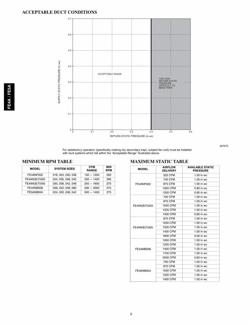
ACCEPTABLE DUCT CONDITIONS
00
0.1
0.2
0.3
0.4
0.5
0.6
0.7
0.1 0.2 0.3 0.4 0.5 0.6
RETURN STATIC PRESSURE (in wc)
SU
PP
LY S
TA
TIC
PR
ES
SU
RE
(in
wc)
TOO HIGHRETURN STATICPRESSURE(DIFFICULT TO MAKE TRAP)
ACCEPTABLE RANGE
A07273
For satisfactory operation (specifically making dry secondary trap), subject fan coils must be installedwith duct systems which fall within the “Acceptable Range” illustrated above.
MINIMUM RPM TABLE
MODEL SYSTEM SIZES CFMRANGE
MINRPM
FE4ANF002 018, 024, 030, 036 150 --- 1200 300FE4AN(B,F)003 024, 030, 036, 042 200 --- 1400 285FE4AN(B,F)005 030, 036, 042, 048 250 --- 1600 275FE4ANB006 036, 042, 048, 060 500 --- 2000 275FE5ANB004 024, 030, 036, 042 500 --- 1400 275
MAXIMUM STATIC TABLE
MODEL AIRFLOWDELIVERY
AVAILABLE STATICPRESSURE
FE4ANF002
525 CFM 1.00 in wc700 CFM 1.00 in wc875 CFM 1.00 in wc1050 CFM 0.80 in wc1200 CFM 0.60 in wc
FE4AN(B,F)003
700 CFM 1.00 in wc875 CFM 1.00 in wc1050 CFM 1.00 in wc1225 CFM 1.00 in wc1400 CFM 0.80 in wc
FE4AN(B,F)005
875 CFM 1.00 in wc1050 CFM 1.00 in wc1225 CFM 1.00 in wc1400 CFM 1.00 in wc1600 CFM 0.50 in wc
FE4ANB006
1050 CFM 1.00 in wc1225 CFM 1.00 in wc1400 CFM 1.00 in wc1750 CFM 1.00 in wc2000 CFM 0.60 in wc
FE5ANB004
700 CFM 1.00 in wc875 CFM 1.00 in wc1050 CFM 1.00 in wc1225 CFM 1.00 in wc1400 CFM 1.00 in wc
FE4A/FE5A

9
GROSS COOLING CAPACITIES (MBTUH)INDOOR COIL
AIRSATURATED TEMPERATURE LEAVING EVAPORATOR (_F / _C)
35 / 2 40 / 4 45 / 7 50 / 10 55 / 13CFM EWB TC SHC BF TC SHC BF TC SHC BF TC SHC BF TC SHC BF
FE4ANF002
50072/22 40.19 19.65 0.00 36.23 17.59 0.00 31.86 15.48 0.00 27.00 13.31 0.00 21.65 11.11 0.0067/19 32.99 19.92 0.01 28.96 17.79 0.01 24.52 15.62 0.01 19.64 13.40 0.01 14.28 11.17 0.0162/17 26.44 20.11 0.01 22.36 17.93 0.01 17.93 15.73 0.01 13.56 13.56 0.03 11.28 11.28 0.19
65072/22 49.76 24.23 0.00 44.85 21.76 0.00 39.40 19.20 0.00 33.36 16.55 0.01 26.66 13.83 0.0167/19 40.90 24.80 0.01 35.90 22.22 0.01 30.37 19.55 0.02 24.27 16.82 0.02 17.58 14.06 0.0262/17 32.84 25.24 0.02 27.75 22.56 0.02 22.25 19.85 0.02 17.13 17.13 0.06 14.25 14.25 0.21
87572/22 61.99 30.08 0.00 55.87 27.15 0.00 49.04 24.04 0.01 41.48 20.80 0.02 33.10 17.46 0.0267/19 51.08 31.23 0.03 44.83 28.09 0.03 37.91 24.84 0.03 30.23 21.47 0.03 21.83 18.03 0.0362/17 41.11 32.14 0.03 34.76 28.88 0.03 27.91 25.53 0.04 22.04 22.04 0.10 18.33 18.33 0.25
100072/22 67.83 32.91 0.00 61.10 29.76 0.00 53.66 26.40 0.02 45.36 22.89 0.03 36.17 19.27 0.0367/19 55.96 34.39 0.04 49.12 31.01 0.04 41.53 27.48 0.04 33.11 23.83 0.04 23.88 20.06 0.0462/17 45.09 35.62 0.04 38.13 32.08 0.04 30.69 28.43 0.05 24.54 24.54 0.12 20.40 20.40 0.27
125072/22 77.77 37.84 0.00 70.13 34.30 0.03 61.59 30.55 0.05 52.04 26.60 0.05 41.42 22.50 0.0567/19 64.36 40.02 0.06 56.52 36.24 0.06 47.77 32.27 0.06 38.04 28.12 0.06 27.46 23.81 0.0762/17 51.98 41.92 0.06 44.00 37.93 0.06 35.61 33.77 0.08 29.12 29.12 0.16 24.20 24.20 0.30
FE4ANF003
60072/22 43.01 20.98 0.00 38.69 18.78 0.00 33.92 16.51 0.00 28.64 14.18 0.00 22.85 11.81 0.0167/19 35.27 21.34 0.01 30.88 19.04 0.01 26.07 16.71 0.01 20.79 14.34 0.01 15.03 11.95 0.0162/17 28.24 21.59 0.01 23.81 19.25 0.01 19.05 16.90 0.02 14.56 14.56 0.05 12.11 12.11 0.21
80072/22 53.83 26.15 0.00 48.40 23.49 0.00 42.36 20.71 0.00 35.72 17.83 0.02 28.38 14.89 0.0267/19 44.23 26.92 0.02 38.71 24.10 0.02 32.61 21.20 0.03 25.91 18.24 0.03 18.65 15.26 0.0362/17 35.47 27.49 0.03 29.87 24.58 0.03 23.89 21.65 0.03 18.67 18.67 0.09 15.51 15.51 0.24
100072/22 63.07 30.60 0.00 56.66 27.57 0.00 49.58 24.36 0.02 41.76 21.04 0.03 33.10 17.62 0.0367/19 51.91 31.82 0.04 45.41 28.58 0.04 38.24 25.24 0.04 30.31 21.78 0.04 21.76 18.29 0.0562/17 41.71 32.80 0.04 35.12 29.43 0.04 28.13 26.00 0.05 22.41 22.41 0.12 18.60 18.60 0.27
120072/22 71.01 34.48 0.00 63.77 31.12 0.02 55.79 27.57 0.04 46.95 23.88 0.05 37.18 20.08 0.0567/19 58.54 36.17 0.05 51.21 32.59 0.05 43.10 28.87 0.06 34.13 25.02 0.06 24.47 21.08 0.0662/17 47.12 37.60 0.06 39.70 33.86 0.06 31.89 30.00 0.07 25.83 25.83 0.15 21.43 21.43 0.29
140072/22 77.95 37.95 0.01 70.07 34.31 0.04 61.29 30.47 0.06 51.54 26.47 0.06 40.78 22.33 0.0767/19 64.44 40.15 0.07 56.37 36.28 0.07 47.43 32.24 0.07 37.54 28.04 0.07 26.89 23.69 0.0862/17 51.95 42.08 0.07 43.78 37.99 0.08 35.30 33.73 0.09 28.95 28.95 0.19 24.01 24.01 0.32
FE5ANB004
60072/22 40.42 19.84 0.00 36.59 17.80 0.00 32.35 15.70 0.00 27.64 13.54 0.00 22.39 11.33 0.0067/19 33.22 20.00 0.00 29.31 17.90 0.00 24.99 15.74 0.00 20.19 13.53 0.00 14.87 11.27 0.0062/17 26.67 20.11 0.00 22.69 17.95 0.00 18.31 15.75 0.00 13.60 13.54 0.00 11.29 11.29 0.17
80072/22 52.07 25.46 0.00 47.19 22.92 0.00 41.75 20.28 0.00 35.66 17.53 0.00 28.84 14.70 0.0067/19 42.88 25.89 0.00 37.88 23.24 0.00 32.31 20.49 0.00 26.10 17.66 0.00 19.18 14.75 0.0062/17 34.51 26.21 0.00 29.39 23.46 0.00 23.73 20.64 0.00 17.81 17.81 0.01 14.85 14.85 0.18
100072/22 62.54 30.48 0.00 56.75 27.53 0.00 50.25 24.45 0.00 42.94 21.21 0.00 34.73 17.84 0.0067/19 51.63 31.28 0.00 45.66 28.17 0.01 38.98 24.93 0.01 31.49 21.55 0.01 23.12 18.06 0.0162/17 41.65 31.91 0.01 35.51 28.66 0.01 28.71 25.30 0.01 21.89 21.89 0.03 18.26 18.26 0.19
120072/22 71.89 34.94 0.00 65.33 31.70 0.00 57.89 28.24 0.00 49.50 24.59 0.00 40.06 20.76 0.0067/19 59.49 36.20 0.01 52.68 32.73 0.01 45.02 29.06 0.01 36.39 25.22 0.01 26.71 21.21 0.0162/17 48.10 37.22 0.01 41.07 33.55 0.01 33.27 29.72 0.01 25.77 25.77 0.05 21.51 21.51 0.20
140072/22 80.24 38.94 0.00 73.00 35.45 0.00 64.73 31.69 0.00 55.41 27.69 0.01 44.86 23.46 0.0167/19 66.53 40.71 0.01 58.99 36.93 0.01 50.47 32.91 0.02 40.84 28.66 0.02 29.98 24.20 0.0262/17 53.91 42.17 0.02 46.10 38.14 0.02 37.43 33.92 0.02 29.46 29.46 0.07 24.60 24.60 0.22
FE4ANF005
75072/22 57.24 28.01 0.00 51.64 25.08 0.00 45.46 22.08 0.00 38.59 19.00 0.00 30.99 15.85 0.0067/19 46.98 28.35 0.00 41.29 25.33 0.00 35.01 22.24 0.00 28.09 19.09 0.00 20.47 15.90 0.0162/17 37.67 28.59 0.01 31.89 25.50 0.01 25.61 22.37 0.01 19.28 19.28 0.02 16.05 16.05 0.19
95072/22 69.68 33.97 0.00 62.89 30.52 0.00 55.32 26.92 0.00 46.89 23.21 0.00 37.57 19.40 0.0067/19 57.29 34.68 0.01 50.33 31.06 0.01 42.64 27.33 0.01 34.14 23.51 0.01 24.80 19.63 0.0162/17 45.99 35.21 0.01 38.92 31.47 0.01 31.24 27.68 0.01 23.90 23.90 0.04 19.89 19.89 0.20
115072/22 80.80 39.28 0.00 72.96 35.40 0.00 64.17 31.32 0.00 54.37 27.06 0.01 43.48 22.66 0.0167/19 66.56 40.46 0.02 58.50 36.34 0.02 49.54 32.05 0.02 39.60 27.64 0.02 28.70 23.15 0.0262/17 53.51 41.36 0.02 45.29 37.07 0.02 36.38 32.70 0.02 28.26 28.26 0.07 23.51 23.51 0.22
150072/22 97.47 47.29 0.00 88.05 42.83 0.00 77.49 38.05 0.01 65.68 33.04 0.02 52.41 27.78 0.0267/19 80.52 49.40 0.03 70.85 44.58 0.03 60.01 39.53 0.03 47.89 34.25 0.03 34.64 28.83 0.0462/17 64.96 51.12 0.03 55.02 46.04 0.03 44.30 40.80 0.04 35.27 35.27 0.10 29.34 29.34 0.25
170072/22 105.61 51.26 0.00 95.43 46.52 0.01 84.03 41.43 0.03 71.21 36.06 0.03 56.82 30.42 0.0367/19 87.38 53.92 0.04 76.93 48.80 0.04 65.20 43.40 0.04 52.01 37.70 0.04 37.60 31.83 0.0562/17 70.60 56.17 0.04 59.87 50.74 0.04 48.32 45.08 0.05 38.96 38.96 0.13 32.40 32.40 0.27
FE4ANB006
105072/22 76.01 37.07 0.00 68.82 33.39 0.00 60.76 29.56 0.00 51.72 25.55 0.00 41.64 21.42 0.0067/19 62.63 37.91 0.01 55.22 34.04 0.01 46.97 30.03 0.01 37.78 25.89 0.01 27.60 21.64 0.0162/17 50.40 38.54 0.01 42.81 34.53 0.01 34.49 30.41 0.01 26.28 26.28 0.03 21.90 21.90 0.19
130072/22 89.66 43.58 0.00 81.26 39.43 0.00 71.77 35.02 0.00 61.13 30.39 0.00 49.17 25.55 0.0167/19 74.04 45.04 0.01 65.36 40.60 0.01 55.62 35.94 0.01 44.72 31.09 0.01 32.62 26.09 0.0162/17 59.73 46.18 0.01 50.78 41.52 0.02 40.97 36.70 0.02 31.77 31.77 0.06 26.48 26.48 0.21
175072/22 110.09 53.41 0.00 99.92 48.64 0.00 88.41 43.46 0.01 75.38 37.95 0.02 60.66 32.13 0.0267/19 91.28 56.16 0.02 80.74 50.96 0.03 68.83 45.42 0.03 55.35 39.55 0.03 40.35 33.42 0.0362/17 73.94 58.45 0.03 63.04 52.91 0.03 51.08 47.08 0.03 40.82 40.82 0.10 34.04 34.04 0.24
205072/22 121.19 58.89 0.00 110.14 53.79 0.01 97.57 48.25 0.02 83.25 42.30 0.03 67.02 35.98 0.0367/19 100.75 62.56 0.04 89.24 56.99 0.04 76.15 51.01 0.04 61.30 44.63 0.04 44.72 37.88 0.0462/17 81.81 65.71 0.04 69.88 59.72 0.04 56.88 53.37 0.05 46.27 46.27 0.12 38.60 38.60 0.26
220072/22 126.10 61.36 0.00 114.71 56.14 0.02 101.67 50.45 0.03 86.78 44.32 0.03 69.87 37.76 0.0467/19 104.99 65.51 0.04 93.05 59.79 0.04 79.44 53.62 0.04 63.97 47.02 0.04 46.71 40.00 0.0562/17 85.35 69.12 0.04 72.98 62.94 0.05 59.55 56.35 0.06 48.85 48.85 0.14 40.75 40.75 0.27
FE4A/FE5A

10
CFM --- Cubic Ft per Minute EWB --- Entering Wet Bulb (_F / _C) LWB --- Leaving Wet Bulb (_F / _C) TC --- Gross Cooling Capacity 1000 BtuhSHC --- Gross Sensible Capacity 1000 Btuh BF --- Bypass Factor MBH --- 1000 Btuh
NOTES:1. Contact manufacturer for cooling capacities at conditionsother than shown in table.
2. Formulas:Leaving db = entering db ---sensible heat cap.
1.09 x CFMLeaving wb = wb corresponding to enthalpy of air leav-ing coil (hlwb)hlwb = hewb ---total capacity (Btuh)
4.5 x CFMwhere hewb = enthalpy of air entering coil. Direct inter-polation is permissible. Do not extrapolate.
3. SHC is based on 80_F db temperature of air entering coil.Below 80_F db, subtract (Correction Factor x CFM) fromSHC. Above 80_F db, add (Correction Factor x CFM) toSHC.
4. Bypass Factor = 0 indicates no psychometric solution.Use bypass factor of next lower EWB for approximation.
SHC CORRECTION FACTOR
BYPASSFACTOR
ENTERING AIR DRY--BULB TEMPERATURE (_F)
79 78 77 76 75 Under 75
81 82 83 84 85 Over 85
Correction Factor
0.10 .098 1.96 2.94 3.92 4.91Use formulashownbelow
0.20 0.87 1.74 2.62 3.49 4.36
0.30 0.76 1.53 2.29 3.05 3.82
Interpolation is permissible.Correction Factor = 1.09 x (1 --- BF) x (db --- 80)
ESTIMATED SOUND POWER LEVEL (dBA)MODELSIZE
CONDITIONS OCTAVE BAND CENTER FREQUENCYCFM ESP 63 125 250 500 1000 2000 4000
FE4ANF002
400 0.25 61.0 57.0 55.0 50.0 48.0 46.0 42.0600 0.25 62.7 58.7 56.7 51.7 49.7 47.7 43.7800 0.25 64.0 60.0 58.0 53.0 51.0 49.0 45.01000 0.25 65.0 61.0 57.0 56.0 52.0 50.0 46.01200 0.25 65.8 61.8 57.8 56.8 52.8 50.8 46.81400 0.25 66.4 62.4 58.4 57.4 53.4 51.4 47.4
FE4ANF003
400 0.25 61.0 57.0 55.0 50.0 48.0 46.0 42.0600 0.25 62.7 58.7 56.7 51.7 49.7 47.7 43.7800 0.25 64.0 60.0 58.0 53.0 51.0 49.0 45.01000 0.25 65.0 61.0 59.0 54.0 52.0 50.0 46.01200 0.25 65.8 61.8 59.8 54.8 52.8 50.8 46.81400 0.25 66.4 62.4 58.4 57.4 53.4 51.4 47.41600 0.25 67.0 63.0 59.0 58.0 54.0 52.0 48.0
FE5ANB004
600 0.25 62.7 58.7 56.7 51.7 49.7 47.7 43.7800 0.25 64.0 60.0 58.0 53.0 51.0 49.0 45.01000 0.25 65.0 61.0 59.0 54.0 52.0 50.0 46.01200 0.25 65.8 61.8 59.8 54.8 52.8 50.8 46.81400 0.25 66.4 62.4 60.4 55.4 53.4 51.4 47.41600 0.25 67.0 63.0 61.0 56.0 54.0 52.0 48.0
FE4ANF005
400 0.25 61.0 57.0 55.0 50.0 48.0 46.0 42.0600 0.25 62.7 58.7 56.7 51.7 49.7 47.7 43.7800 0.25 64.0 60.0 58.0 53.0 51.0 49.0 45.01000 0.25 65.0 61.0 59.0 54.0 52.0 50.0 46.01200 0.25 65.8 61.8 59.8 54.8 52.8 50.8 46.81400 0.25 66.4 62.4 58.4 57.4 53.4 51.4 47.41600 0.25 67.0 63.0 59.0 58.0 54.0 52.0 48.0
FE4ANB006
600 0.25 62.7 58.7 56.7 51.7 49.7 47.7 43.7800 0.25 64.0 60.0 58.0 53.0 51.0 49.0 45.01000 0.25 65.0 61.0 59.0 54.0 52.0 50.0 46.01200 0.25 65.8 61.8 59.8 54.8 52.8 50.8 46.81400 0.25 66.4 62.4 60.4 55.4 53.4 51.4 47.41600 0.25 67.0 63.0 61.0 56.0 54.0 52.0 48.01800 0.25 67.5 63.5 59.5 58.5 54.5 52.5 48.52000 0.25 68.0 64.0 60.0 59.0 55.0 53.0 49.02150 0.25 68.3 64.3 60.3 59.3 55.3 53.3 49.3
*Est. sound power levels have been derived using the method described in the 1987 ASHRAE HVAC Systems & Applications Handbook, chapter 52, p. 52.7.
AIRFLOW PERFORMANCE CORRECTION FACTORS
HEATER KW ELEMENTSSTATIC PRESSURE CORRECTION (in wc)
Sizes 002–005 Size 0060 0 +.02 +.035 1 +.01 +.028, 10 2 0 09, 15 3 –.02 –.0320 4 –.04 –.06
18, 24, 30 6 –.06 –.10The FE4A airflow performance table was developed using fan coils with 10kW electric heaters (2 elements) in the units. For fan coils with heaters made up of a differ-ent number of elements, the external available static at a given CFM from the table may be corrected by adding or subtracting pressure. Use table for this correction.
FE4A/FE5A

11
FACTORY--INSTALLED FILTER STATIC PRESSURE DROP (in wc)MODEL CFMFE4A 400 600 800 1000 1200 1400 1600 1800 2000002 0.020 0.044 0.048 0.072 0.100 — — — —003 — 0.020 0.035 0.051 0.070 0.092 — — —005 — — 0.035 0.051 0.070 0.092 0.120 — —006 — — — 0.038 0.053 0.070 0.086 0.105 0.133
MODEL CFMFE5A 400 600 800 1000 1200 1400 1600 1800 2000004 — 0.015 0.026 0.038 0.053 0.070 — — —
AIR DELIVERY PERFORMANCE CORRECTION COMPONENT PRESSURE DROP (in wc)AT INDICATED AIRFLOW (DRY TO WET COIL)MODELFE4A
CFM600 700 800 900 1000 1100 1200 1300 1400 1500 1600
002 0.012 0.016 0.022 0.028 0.034 0.040 0.049 — — — —003 — 0.026 0.034 0.042 0.052 0.063 0.075 0.083 0.091 0.098 0.110005 — 0.006 0.008 0.010 0.012 0.015 0.017 0.020 0.023 0.027 0.030
CFM1100 1200 1300 1400 1500 1600 1700 1800 1900 2000 2100
006 0.013 0.016 0.018 0.020 0.023 0.027 0.030 0.034 0.039 0.044 0.048MODELFE5A
CFM600 700 800 900 1000 1100 1200 1300 1400 1500 1600
004 0.004 0.005 0.007 0.009 0.011 0.013 0.016 0.018 0.020 0.023 —NOTE: Subtract the above pressure drop corrections from unit airflow data when that component or condition is used. The remaining external static pressure
will be available for the duct system.
UNITS WITHOUT ELECTRIC HEAT
UNIT SIZE VOLTS---PHASE FLA MIN CKT AMPSBRANCH CIRCUIT
Min Wire Size Awg* Fuse/Ckt Bkr Amps002 208/230---1 4.3 5.4 14 15003 208/230---1 4.3 5.4 14 15005 208/230---1 4.3 5.4 14 15
004, 006 208/230---1 6.8 8.5 14 15* Use copper wire only to connect unit. If other than uncoated (non---plated) 75° C ambient, copper wire (solid wire for 10 AWG and smaller, stranded wire forlarger than 10 AWG) is used consult applicable tables of the National Electric Code (ANSI/NFPA 70).
NOTE: If branch circuit wire length exceeds 100 ft / 30.5 m, consult NEC 210---19a to determine maximum wire length. Use 2% voltage drop.FLA — Full Load Amps
ACCESSORY ELECTRIC HEATERSHEATERPART NO.
kW@240V
VOLTS/PHASE
STAGES (kWOPERATING)
INTERNALCIRCUIT
PROTECTION
FAN COILSIZE USEDWITH
HEATING CAP.@ 230V‡
INTELLIGENTHEAT CAPABLE(kW OPERATING)
KFCEH0501N05 5 230/1 5 None All 15,700 —KFCEH0901N10 10 230/1 10 None All 31,400 —KFCEH3001F15 15 230/1 5, 15 Fuses** All 47,100 5, 10, 15KFCEH3201F20 20 230/1 5, 20 Fuses** All 62,800 5, 10, 15, 20KFCEH2901N09 9 230/1* 3, 9 None All 28,300 3, 6, 9KFCEH1601315 15 230/3 5, 15 None All 47,100 —KFCEH3401F24 24 230/3† 8, 16, 24 Fuses 005, 006 78,500 8, 16, 24KFCEH3501F30 30 230/3† 10, 20, 30 Fuses 005, 006 94,200 10, 20, 30KFCEH2401C05 5 230/1 5 Ckt Bkr All 15,700 —KFCEH2601C10 10 230/1 10 Ckt Bkr All 31,400 —KFCEH3101C15 15 230/1 5, 15 Ckt Bkr All 47,100 5, 10, 15KFCEH3301C20 20 230/1 5, 20 Ckt Bkr All 62,800 5, 10, 15, 20
* Field convertible to 3 phase.{ These heaters field convertible to single phase.** Single point wiring kit required for these heaters in Canada.‡ Blower motor heat not included.
ELECTRIC HEATER INTERNAL PROTECTIONHEATER kW PHASE FUSES QTY / SIZE CKT BKR QTY / SIZE*
5 1 — 1/608 1 — 1/609 1/3 — —10 1 — 1/6015 1 2/30, 2/60 2/6015 3 — —18 3 — —20 1 4/60 2/6024 3/1 6/60 —30 3/1 6/60 —
* All circuit breakers are 2 pole.
FE4A/FE5A

12
ACCESSORYELECTRIC
HEATERELECTRICALDATA
HEATER
PARTNO.
kWP H A S E
INTERNAL
CIRCUIT
PROTEC-
TION
HEATERAMPS
208/230V
BRANCHCIRCUIT
MinAmpacity
208/230V**
MinWireSize(AWG)
208/230V††
MinGndWireSize
208/230V
MaxFuse/CktBkrAmps
208/230V
MaxWireLength
208/230V(ft)‡‡
Single
Circuit
DualCircuit
Single
Circuit
DualCircuit
Single
Circuit
DualCircuit
Single
Circuit
DualCircuit
Single
Circuit
DualCircuit
Single
Circuit
DualCircuit
240v
208v
L1,L2
L3,L4
L1,L2
L3,L4
L1,L2
L3,L4
L1,L2
L3,L4
L1,L2
L3,L4
L1,L2
L3,L4
KFCEH0501N05
53.8
1None
18.1/20.0
——
31.2/33.5
——
8/8
——
10/10
——
35/35
——
85/88
——
KFCEH2401C05
53.8
1CktBkr
18.1/20.0
——
31.2/33.5
——
8/8
——
10/10
——
35/35
——
85/88
——
KFCEH0801N08
86.0
1None
28.9/32.0
——
44.7/48.5
——
8/8
——
10/10
——
45/50
——
59/60
——
KFCEH2501C08
86.0
1CktBkr
28.9/32.0
——
44.7/48.5
——
8/8
——
10/10
——
45/50
——
59/60
——
KFCEH2901N09*
96.8
1None
32.8/36.0
——
49.5/53.5
——
8/6
——
10/10
——
50/60
——
54/87
——
KFCEH2901N09*‡
96.8
3None
18.8/20.8
——
32.0/34.5
——
8/8
——
10/10
——
35/35
——
83/85
——
KFCEH0901N10
107.5
1None
36.2/40.0
——
53.8/58.5
——
6/6
——
10/10
——
60/60
——
78/80
——
KFCEH2601C10
107.5
1CktBkr
36.2/40.0
——
53.8/58.5
——
6/6
——
10/10
——
60/60
——
78/80
——
KFCEH3001F15*1
1511.3
1Fuse
54.2/59.9
36.2/40.0
18.1/20.0
76.3/83.4
53.8/58.5
22.7/25.0
4/4
6/6
10/10
8/8
10/10
10/10
80/90
60/60
25/25
88/89
78/80
75/76
KFCEH3101C15*
1511.3
1CktBkr
—36.2/40.0
18.1/20.0
—53.8/58.5
22.7/25.0
—6/6
10/10
—10/10
10/10
—60/60
25/25
—78/80
75/76
KFCEH1601315
1511.3
3None
31.3/34.6
——
47.7/51.8
——
8/6
——
10/10
——
50/60
——
56/90
——
KFCEH2001318
1813.5
3None
37.6/41.5
——
55.5/60.4
——
6/6
——
10/8
——
60/70
——
76/77
——
KFCEH3201F20*1
2015.0
1Fuse
72.3/79.9
36.2/40.0
36.2/40.0
98.9/108.4
53.8/58.5
45.3/50.0
3/2
6/6
8/8
8/6
10/10
10/10
100/110
60/60
50/50
85/109
78/80
59/59
KFCEH3301C20*
2015.0
1CktBkr
—36.2/40.0
36.2/40.0
—53.8/58.5
45.3/50.0
—6/6
8/8
—10/10
10/10
—60/60
50/50
—78/80
59/59
KFCEH3401F24*†
2418.0
3Fuse
50.1/55.4
——
71.2/77.8
——
4/4
——
8/8
——
80/80
——
94/95
——
2418.0
1Fuse
86.7/95.5
——
116.9/127.9
——
1/1
——
6/6
——
125/150
——
115/116
——
KFCEH3501F30*†
3022.5
3Fuse
62.6/69.2
——
86.8/95.0
——
3/3
——
8/8
——
90/100
——
97/98
——
3022.5
1Fuse
109.0/120.0
——
144.8/158.5
——
0/00
——
6/6
——
150/175
——
117/150
——
FIELDMULT
IPOINTWIRINGOF24--AND30--kW
SINGLEPHASE
HEATERPART
NO.
kWP H A S E
HEATERAMPS
208/230V
MINAMPACITY
208/230V**
MINWIRESIZE(AWG)
208/230V††
MINGND
WIRESIZE
208/230V
MAXFUSE/CKTBKR
AMPS
208/230V
MAXWIRELENGTH
208/230V(FT)‡‡
240V
208V
L1,L2
L3,L4
L5,L6
L1,L2
L3,L4
L5,L6
L1,L2
L3,L4
L5,L6
L1,L2
L3,L4
L5,L6
L1,L2
L3,L4
L5,L6
KFCEH3401F24*†
2418.0
128.9/32.0
28.9/32.0
28.9/32.0
44.7/48.5
36.2/40.0
36.2/40.0
8/8
8/8
8/8
10/10
45/50
40/40
40/40
59/60
73/73
73/73
KFCEH3501F30*†
3022.5
136.2/40.0
36.2/40.0
36.2/40.0
53.8/58.5
45.3/50.0
45.3/50.0
6/6
8/8
8/8
10/10
60/60
50/50
50/50
78/80
59/59
59/59
*HeatersareIntelligentHeatcapablewhenusedwiththeFEfancoilandComfortZoneIItorInfinityControlt.
{Fieldconvertibleto1phase,singleormultiplesupplycircuit.
}Fieldconvertibleto3phase.
**Includesblowermotorampsoflargestfancoilusedwithheater.
{{Copperwiremustbeused.Ifotherthanuncoated(non---plated),75_Cambient,copperwire(solidwirefor10AWGandsmaller,strandedwireforlargerthan10AWG)isused,consultapplicabletablesof
theNationalElectricCode(ANSI/NFPA70).
}}Lengthshownisasmeasured1wayalongwirepathbetweenunitandservicepanelforavoltagedropnottoexceed2%.
NOTES:
1.SinglecircuitapplicationofF15andF20heatersrequiressingle---pointwiringkitaccessory.
FE4A/FE5A

13
ACCESSORIES
REQUIRED ACCESSORY
ITEM ACCESSORY PARTNO.* FAN COIL SIZE USED WITH
1.
Infinityr Touch Control with Integrated Wi---Fi SYSTXCCITC01 Allor
Infinityr Touch Control Wi---Fiwith bundled router SYSTXCCITW01 All
orInfinityr Touch Control SYSTXCCITN01 All
ADDITIONAL ACCESSORIES
ITEM ACCESSORY PARTNO.* FAN COIL SIZE USED WITH
2. Infinityr Series 4 Zone Board SYSTXCC4ZC01 All3. Infinityr Series Smart Sensor SYSTXCCSMS01---A All4. Infinityr Remote Room Sensor SYSTXCCRRS01 All5. Infinityr Series Network Interface Module SYSTXCCNIM01 All6. Disconnect Kit KFADK0201DSC Cooling controls and heaters 3--- through 10---kW
7. Downflow Base KitKFACB0201CFB 002KFACB0301CFB 003, 005KFACB0401CFB 004, 006
8. Downflow Conversion KitKFADC0201SLP 003KFADC0401ACL 002, 004, 005, 006
9. Single---Point Wiring Kit KFASP0101SPK Only with 15--- and 20---kW Fused Heaters
10. Filter Kit (12 Pack)KFAFK0212MED 002KFAFK0312LRG 003, 005KFAFK0412XXL 004, 006
11. Filter Media CabinetFNCCABCC0017 002FNCCABCC0021 003, 005FNCCABCC0024 004, 006
12. Media Filter CartridgesFILCCFNC0017 002FILCCFNC0021 003, 005FILCCFNC0024 004, 006
13. Infinityr Series Air PurifierGAPABXCC1620 002GAPABXCC2020 003, 005GAPABXCC2024 004, 006
14. PVC Condensate Trap Kit (50 pack) KFAET0150ETK All15. Air Cleaner 240---volt Conversion Kit KEAVC0201240 All16. Downflow/Horizontal Conversion Gasket Kit KFAHD0101SLP All17. Airflow Sensor Kit (Air Cleaner) KEAAC0101AAA All18. Horizontal Water Management Kit (25 pack) KFAHC0125AAA All
19. Standard Filter Rack Kit
KFAFR0101FRM NAKFAFR0201FRM 002KFAFR0301FRM 003, 005KFAFR0401FRM 004, 006
20. Hydronic Relay Interface Kit KFAIF0101HWC All
* Factory authorized and listed, field installed.
FE4A/FE5A

14
ACCESSORIES (CONT.)Accessory Kits Description Suggested and Required Use
1. Infinityr Touch Control with Integrated Wi--FiDeluxe programmable wall--mounted system control with integrated Wi--Fi.orInfinityr Touch Control Wi--Fi with bundled routerDeluxe programmable wall--mounted system control with integrated Wi--Fi.Sold bundled with Wi--Fi routerorInfinityr Touch ControlDeluxe programmable wall--mounted system control without remote access.
2. Infinityr Series 4 Zone Board4--Zone Damper Control Module wall--mounted control.REQUIRED USE: For all four--zone systems. For systems with 5 to 8 zones, a second Damper Control Module is required.
3. Infinityr Series Smart SensorWall control used to monitor temperature and/or fan control.SUGGESTED USE: For use in zone systems.
4. Infinityr Remote Room SensorWired remote temperature sensor for zone control.SUGGESTED USE: For use in zone systems.
5. Infinityr Series Network Interface ModuleConnects Heat Recovery and Energy Recovery Ventilators on non--zoning applications and non--communicating 2--speed units.REQUIRED USE: For non--zoned systems installed with HRV or ERV, Hybrid Heat with non--communicating heatpumps or non--communicating 2--speed units.
6. Disconnect KitThe kit is used to disconnect electrical power to the fan coil so service or maintenance may be performed safely.SUGGESTED USE: Units for 3-- through 10--kW electric resistance heaters and cooling controls.
7. Downflow Base KitThis kit is designed to provide a 1--in. minimum clearance between unit discharge plenum, ductwork, and combustible materials. Italso provides a gap--free seal with the floor.REQUIRED USE: This kit must be used whenever fan coils are used in downflow applications.
8. Downflow Conversion KitFan coils are shipped from the factory for upflow or horizontal--left applications. Downflow conversion kits provide proper condensatewater drainage and support for the coil when used in downflow applications. Separate kits are available for slope coils and A--coils.REQUIRED USE: This kit must be used whenever fan coils are used in downflow applications.
9. Single Point Wiring KitThe single point wiring kit acts as a jumper between L1 and L3 lugs, and between the L2 and L4 lugs. This allows the installer to run2 heavy--gauge, high--voltage wires into the fan coil rather than 4 light--gauge, high--voltage wires.SUGGESTED USE: Fan coils with 15-- and 20--kW fused heaters only.
10. Filter Kit (12 pack)The kit consists of 12 fan coil framed filters. These filters collect large dust particles from the return air entering the fan coil andprevents them from collecting on the coil. This process helps to keep the coil clean, which increases heat transfer and, in turn, theefficiency of the system.SUGGESTED USE: To replace filters in fan coils.REQUIRED USE: All units unless a filter grille is used.
11. Filter Media CabinetThis cabinet is mounted to the fan coil on the return air end and designed to slip over the outer fan coil casing. The cabinets areinsulated using the same insulation as production fan coils. They are designed for the removal of particulates from indoor air usingFILCCFNC00(14, 17, 21, 24) media filter cartridges.SUGGESTED USE: All fan coils.
12. Media Filter CartridgesThese fan coil media filter cartridge kits are designed for the removal of particles from indoor air. The cartridge is installed in the returnair duct next to the air handler or further upstream.SUGGESTED USE: All fan coils.
13. Infinityr Series Air PurifierThe Infinity Series Air Purifier wires directly to fan coil and requires no duct transitions with Carrier units. It comes with an airflowsensor.SUGGESTED USE: All fan coils.
14. Condensate Drain Trap KitThis kit consists of 50 PVC condensate traps. Each trap is pre--formed and ready for field installation. This deep trap helps the systemmake and hold proper condensate flow even during blower initiation.SUGGESTED USE: All fan coils.
15. Air Cleaner 240--volt Conversion KitThe AIRA electronic air cleaner comes ready for 115--v operation.REQUIRED USE: This kit is required when running 240--volt circuit to air cleaner.
FE4A/FE5A

15
ACCESSORIES (CONT.)16. Downflow/Horizontal Conversion Gasket Kit
This kit provides the proper gasketing of units when applied in either a downflow or horizontal application.REQUIRED USE: Fan coils in either downflow or horizontal applications.
17. Airflow Sensor Kit (Air Cleaner)The AIRA electronic air cleaner comes ready for 115--v operationREQUIRED USE: This kit is required whenever an electronic air cleaner is used.
18. Horizontal Water Management KitThis kit provides proper installation of fan coils under conditions of high static pressure and high relative humidty.SUGGESTED USE: All fan coils (except FE5 and FF1).
19. Standard Filter Rack KitThis kit mounts in fan coil filter rack area and modifies the existing filter rack to support standard 1--in. filter sizes.SUGGESTED USE: Fan coils using standard filter sizes.
20. Hydronic Relay Interface KitThis kit provides interface of the FE4 and FE5 fan coils with Hydronic Heat equipment.NOTE: Electric heat cannot be used with Hydronic Interface Relay Kit.SUGGESTED USE: All FE4 and FE5 fan coils installed with hydronic heat.
FE4A/FE5A

16
Copyright 2015 Carrier Corp. S 7310 W. Morris St. S Indianapolis, IN 46231 Edition Date: 09/15 U.S. Export Classification: EAR99.
Manufacturer reserves the right to change, at any time, specifications and designs without notice and without obligations.
Catalog No: FE4A---10PD
Replaces: FE4A---09PD
FE4A/FE5A