Embed Size (px)
Citation preview
CATALOGPRODUCT
2
3Siberian Industrial Group
TABLE OF CONTENTS
About company ......................................................................................................................................4
Machine Building DivisionProEnTech Plant ....................................................................................................................................6Certificates and documentation of ProEnTech Plant ...........................................................................8Ball valves manufactured by ProEnTech Plant ............................................................................... 10Design Features ................................................................................................................................. 21Main dimensions ................................................................................................................................ 23Quality control and testing ................................................................................................................. 26Types of repair work ........................................................................................................................... 27
Pipe production division
Izhora Pipe Rolling Plant ................................................................................................................... 28Certificates and documentation of Izhora Pipe Rolling Plant ......................................................... 30Seamless pipes manufactured by IPRP. Specifications .................................................................... 32Seamless conventional pipes and boiler tubes .............................................................................. 44Casing pipes ....................................................................................................................................... 45Pumping and compression pipes ..................................................................................................... 46
Izhevsk Isolation Plant ....................................................................................................................... 48Certificates and documentation of Izhevsk Isolation Plant .............................................................. 50Pipes with external corrosion-resistant coating ............................................................................ 52Pipes with internal corrosion-resistant coating ............................................................................. 56
TVEL-Tobolsk ...................................................................................................................................... 60Certificates and documentation of TVEL-Tobolsk ............................................................................ 62Steel pipes with external corrosion-resistant coating .................................................................. 64Steel pipes and fittings with thermal insulation coating ............................................................... 70
Steel fittings with external corrosion-resistant coating ................................................................... 92Steel fittings with thermal insulation ................................................................................................ 96
Static pipeline support ......................................................................................................................116Movable pipeline support ..................................................................................................................128Fittings ...............................................................................................................................................129
Set of heat shrinking sleeves ............................................................................................................134Sets of materials for insulation of welded joints of oil and gas pipeline ........................................135
4
ABOUT COMPANY
Siberian Industrial Group (Joint-Stock Company) is an industrial holding of the metallurgical and machine building complex of Russia, which dynamically develops an approach to provide the most convenient service and improve the quality of services provided to companies of the fuel and energy complex (FEC). The company is focused on providing the whole range of services - from joint participation in design to operation and after-sales service (warranty service).
Siberian Industrial Group includes the following enterprises:
The Trading house Siberian Industrial Holding (Limited liability Company) is authorized and exclusive agent that carries out the wholerange of sales operations in Russia and abroad.
The Trading House Siberian Industrial Group (Limited liability Company) is an exclusive agent for sales operations of shut-off and control valves with unique technical characteristics.
TVEL-Tobolsk (Joint-Stock Company) is one of the oldest, largest, and most advanced manufacturers of insulated pipes and pipeline fittings in Russia.
Izhevsk Isolation Plant (Limited liability Company) is the leading manufacturer of pipes with internal and external corrosion-resistant coating for the oil and gas industry.
ProEnTech Plant (Limited liability Company) is a machine-building enterprise that is a part of Siberian Industrial Group, manufacturing shut-off and control valves intended for operation at low temperatures, in environments with a high content of hydrogen sulfide and with other features.
Izhora Pipe Rolling Plant (Limited liability Company) – manufacturer of wide range assortment of seamless pipes, including casing and pumping and compression pipes.
6
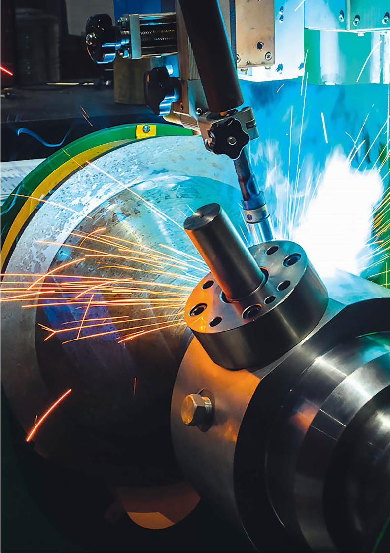
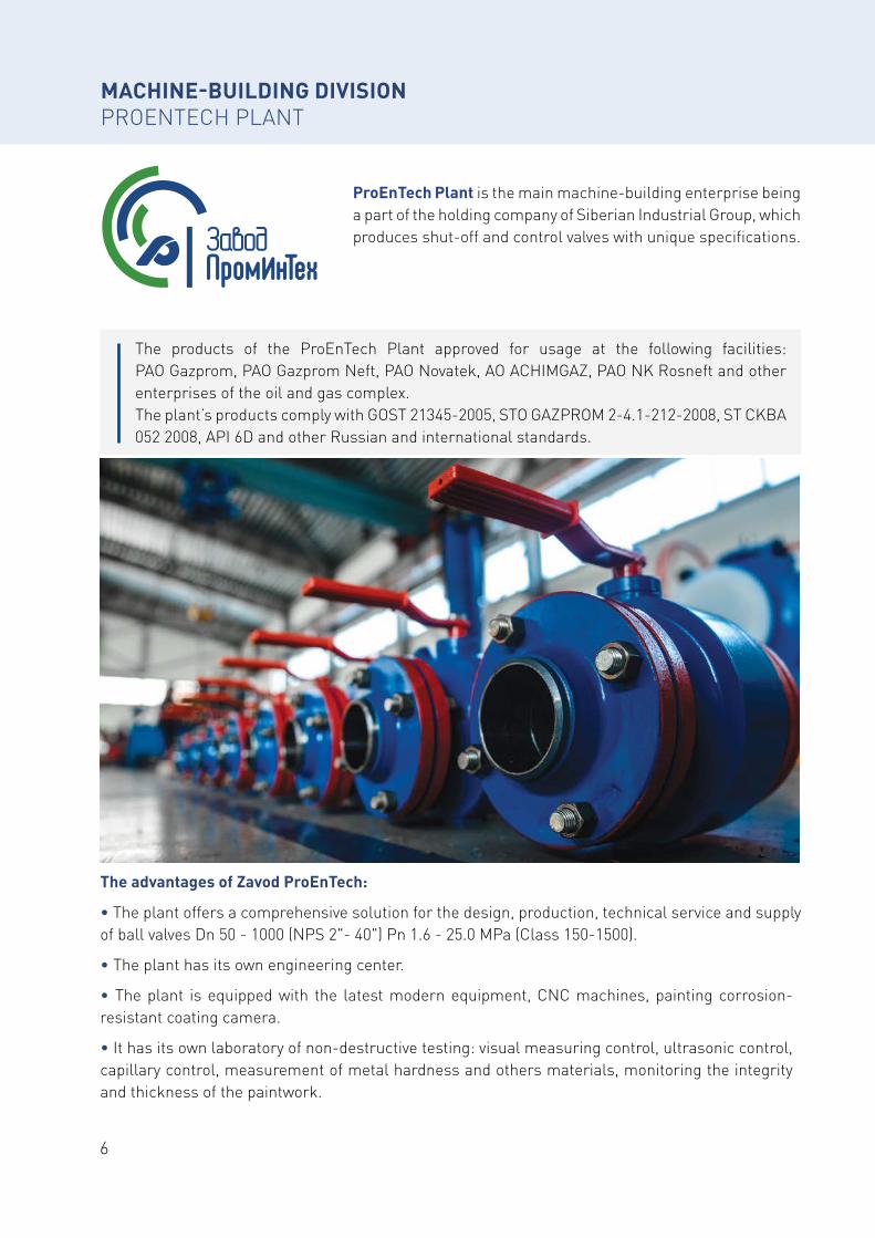
MACHINE-BUILDING DIVISIONPROENTECH PLANT
ProEnTech Plant is the main machine-building enterprise being a part of the holding company of Siberian Industrial Group, which produces shut-off and control valves with unique specifications.
The products of the ProEnTech Plant approved for usage at the following facilities: PAO Gazprom, PAO Gazprom Neft, PAO Novatek, AO ACHIMGAZ, PAO NK Rosneft and other enterprises of the oil and gas complex. The plant’s products comply with GOST 21345-2005, STO GAZPROM 2-4.1-212-2008, ST CKBA 052 2008, API 6D and other Russian and international standards.
The advantages of Zavod ProEnTech:
• The plant offers a comprehensive solution for the design, production, technical service and supply of ball valves Dn 50 - 1000 (NPS 2"- 40") Pn 1.6 - 25.0 MPa (Class 150-1500).
• The plant has its own engineering center.
• The plant is equipped with the latest modern equipment, CNC machines, painting corrosion-resistant coating camera.
• It has its own laboratory of non-destructive testing: visual measuring control, ultrasonic control, capillary control, measurement of metal hardness and others materials, monitoring the integrity and thickness of the paintwork.
7Siberian Industrial Group
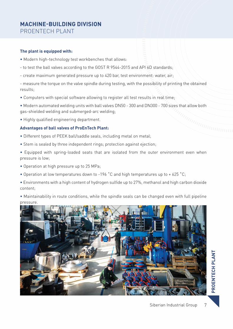
The plant is equipped with:
• Modern high-technology test workbenches that allows:
- to test the ball valves according to the GOST R 9544-2015 and API 6D standards;
- create maximum generated pressure up to 420 bar, test environment: water, air;
- measure the torque on the valve spindle during testing, with the possibility of printing the obtained results;
• Computers with special software allowing to register all test results in real time;
• Modern automated welding units with ball valves DN50 - 300 and DN300 - 700 sizes that allow both gas-shielded welding and submerged-arc welding;
• Highly qualified engineering department.
Advantages of ball valves of ProEnTech Plant:
• Different types of PEEK ball/saddle seals, including metal on metal;
• Stem is sealed by three independent rings; protection against ejection;
• Equipped with spring-loaded seats that are isolated from the outer environment even when pressure is low;
• Operation at high pressure up to 25 MPa;
• Operation at low temperatures down to -196 ˚C and high temperatures up to + 625 ˚C;
• Environments with a high content of hydrogen sulfide up to 27%, methanol and high carbon dioxide content;
• Maintainability in route conditions, while the spindle seals can be changed even with full pipeline pressure.
PRO
ENTE
CH P
LAN
T
MACHINE-BUILDING DIVISIONPROENTECH PLANT
8
CERTIFICATES AND DOCUMENTATIONPROENTECH PLANT
9Siberian Industrial Group
CERTIFICATES AND DOCUMENTATIONPROENTECH PLANT
CER
TIFI
CATE
S A
ND
DO
CUM
ENTA
TIO
NPR
OEN
TECH
PLA
NT
10
BALL VALVES MANUFACTURED BY PROENTECH PLANT
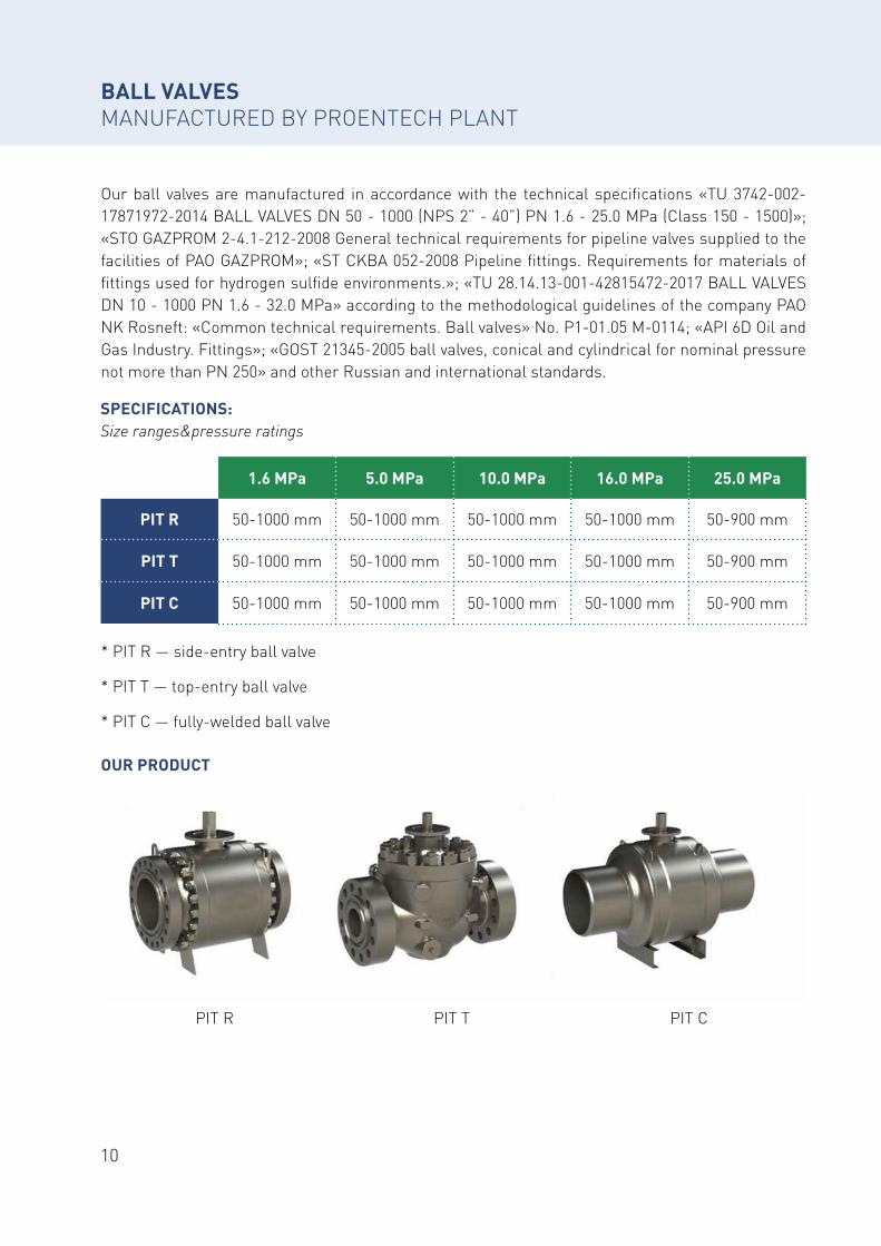
Our ball valves are manufactured in accordance with the technical specifications «TU 3742-002-17871972-2014 BALL VALVES DN 50 - 1000 (NPS 2” - 40”) PN 1.6 - 25.0 MPa (Class 150 - 1500)»; «STO GAZPROM 2-4.1-212-2008 General technical requirements for pipeline valves supplied to the facilities of PAO GAZPROM»; «ST CKBA 052-2008 Pipeline fittings. Requirements for materials of fittings used for hydrogen sulfide environments.»; «TU 28.14.13-001-42815472-2017 BALL VALVES DN 10 - 1000 PN 1.6 - 32.0 MPa» according to the methodological guidelines of the company PAO NK Rosneft: «Common technical requirements. Ball valves» No. P1-01.05 М-0114; «API 6D Oil and Gas Industry. Fittings»; «GOST 21345-2005 ball valves, conical and cylindrical for nominal pressure not more than PN 250» and other Russian and international standards.
SPECIFICATIONS:Size ranges&pressure ratings
OUR PRODUCT
PIT R PIT T PIT C
* PIT R — side-entry ball valve
* PIT T — top-entry ball valve
* PIT C — fully-welded ball valve
1.6 MPa 5.0 MPa 10.0 MРa 16.0 MРa 25.0 MРa
PIT R 50-1000 mm 50-1000 mm 50-1000 mm 50-1000 mm 50-900 mm
PIT T 50-1000 mm 50-1000 mm 50-1000 mm 50-1000 mm 50-900 mm
PIT C 50-1000 mm 50-1000 mm 50-1000 mm 50-1000 mm 50-900 mm
11Siberian Industrial Group
BA
LL V
ALV
ES M
AN
UFA
CTU
RED
B
Y PR
OEN
TECH
PLA
NT
12
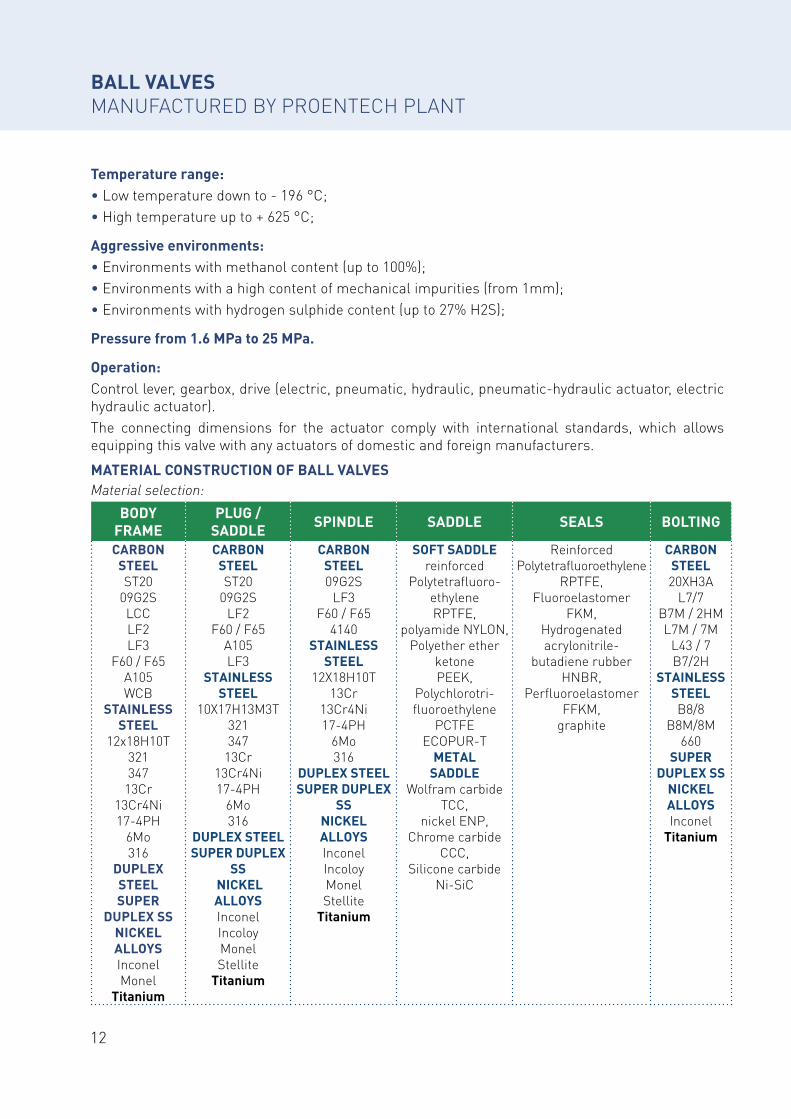
Temperature range:• Low temperature down to - 196 °С;• High temperature up to + 625 °С;
Aggressive environments:• Environments with methanol content (up to 100%);• Environments with a high content of mechanical impurities (from 1mm);• Environments with hydrogen sulphide content (up to 27% H2S);
Pressure from 1.6 MPa to 25 MPa.
Operation:Control lever, gearbox, drive (electric, pneumatic, hydraulic, pneumatic-hydraulic actuator, electric hydraulic actuator).The connecting dimensions for the actuator comply with international standards, which allows equipping this valve with any actuators of domestic and foreign manufacturers.
BALL VALVES MANUFACTURED BY PROENTECH PLANT
MATERIAL CONSTRUCTION OF BALL VALVESMaterial selection:
BODY FRAME
PLUG / SADDLE SPINDLE SADDLE SEALS BOLTING
CARBON STEELST20
09G2SLCCLF2LF3
F60 / F65А105WCB
STAINLESS STEEL
12x18H10T321347
13Сr13Cr4Ni17-4PH
6Mo316
DUPLEX STEELSUPER
DUPLEX SSNICKELALLOYSInconelMonel
Titanium
CARBONSTEELST20
09G2SLF2
F60 / F65A105LF3
STAINLESSSTEEL
10X17H13M3T321347
13Сr13Cr4Ni17-4PH
6Mo316
DUPLEX STEELSUPER DUPLEX
SS NICKELALLOYSInconelIncoloyMonelStellite
Titanium
CARBONSTEEL09G2S
LF3F60 / F65
4140STAINLESS
STEEL12X18H10T
13Сr13Cr4Ni17-4PH
6Mo316
DUPLEX STEELSUPER DUPLEX
SSNICKELALLOYSInconelIncoloyMonelStellite
Titanium
SOFT SADDLEreinforced
Polytetrafluoro-ethyleneRPTFE,
polyamide NYLON,Polyether ether
ketonePEEK,
Polychlorotri-fluoroethylene
PCTFEECOPUR-T
METALSADDLE
Wolfram carbideTCC,
nickel ENP,Chrome carbide
CCC,Silicone carbide
Ni-SiC
ReinforcedPolytetrafluoroethylene
RPTFE,Fluoroelastomer
FKM,Hydrogenated acrylonitrile-
butadiene rubber HNBR,
PerfluoroelastomerFFKM,
graphite
CARBONSTEEL20XH3A
L7/7B7M / 2HML7M / 7M
L43 / 7B7/2H
STAINLESSSTEELB8/8
B8M/8M660
SUPER DUPLEX SS
NICKELALLOYSInconel
Titanium
13Siberian Industrial Group
BODY FRAME
PLUG / SADDLE SPINDLE SADDLE SEALS BOLTING
CARBON STEELST20
09G2SLCCLF2LF3
F60 / F65А105WCB
STAINLESS STEEL
12x18H10T321347
13Сr13Cr4Ni17-4PH
6Mo316
DUPLEX STEELSUPER
DUPLEX SSNICKELALLOYSInconelMonel
Titanium
CARBONSTEELST20
09G2SLF2
F60 / F65A105LF3
STAINLESSSTEEL
10X17H13M3T321347
13Сr13Cr4Ni17-4PH
6Mo316
DUPLEX STEELSUPER DUPLEX
SS NICKELALLOYSInconelIncoloyMonelStellite
Titanium
CARBONSTEEL09G2S
LF3F60 / F65
4140STAINLESS
STEEL12X18H10T
13Сr13Cr4Ni17-4PH
6Mo316
DUPLEX STEELSUPER DUPLEX
SSNICKELALLOYSInconelIncoloyMonelStellite
Titanium
SOFT SADDLEreinforced
Polytetrafluoro-ethyleneRPTFE,
polyamide NYLON,Polyether ether
ketonePEEK,
Polychlorotri-fluoroethylene
PCTFEECOPUR-T
METALSADDLE
Wolfram carbideTCC,
nickel ENP,Chrome carbide
CCC,Silicone carbide
Ni-SiC
ReinforcedPolytetrafluoroethylene
RPTFE,Fluoroelastomer
FKM,Hydrogenated acrylonitrile-
butadiene rubber HNBR,
PerfluoroelastomerFFKM,
graphite
CARBONSTEEL20XH3A
L7/7B7M / 2HML7M / 7M
L43 / 7B7/2H
STAINLESSSTEELB8/8
B8M/8M660
SUPER DUPLEX SS
NICKELALLOYSInconel
Titanium
14
BALL VALVES MANUFACTURED BY PROENTECH PLANT
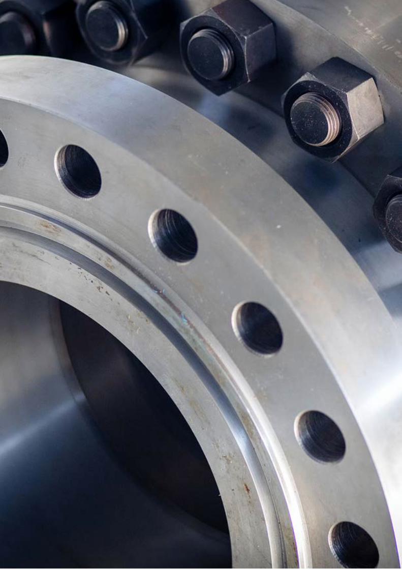
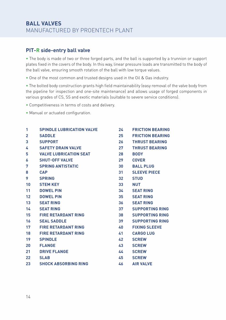
PIT-R side-entry ball valve• The body is made of two or three forged parts, and the ball is supported by a trunnion or support plates fixed in the covers of the body. In this way, linear pressure loads are transmitted to the body of the ball valve, ensuring smooth rotation of the ball with low torque values.
• One of the most common and trusted designs used in the Oil & Gas industry.
• The bolted body construction grants high field maintainability (easy removal of the valve body from the pipeline for inspection and one-site maintenance) and allows usage of forged components in various grades of CS, SS and exotic materials (suitable to severe service conditions).
• Competitiveness in terms of costs and delivery.
• Manual or actuated configuration.
1 SPINDLE LUBRICATION VALVE 2 SADDLE3 SUPPORT4 SAFETY DRAIN VALVE5 VALVE LUBRICATION SEAT6 SHUT-OFF VALVE7 SPRING ANTISTATIC8 CAP9 SPRING10 STEM KEY11 DOWEL PIN12 DOWEL PIN13 SEAT RING14 SEAT RING15 FIRE RETARDANT RING16 SEAL SADDLE17 FIRE RETARDANT RING18 FIRE RETARDANT RING19 SPINDLE20 FLANGE21 DRIVE FLANGE22 SLAB23 SHOCK ABSORBING RING
24 FRICTION BEARING25 FRICTION BEARING26 THRUST BEARING27 THRUST BEARING28 BODY29 COVER30 BALL PLUG31 SLEEVE PIECE32 STUD33 NUT34 SEAT RING35 SEAT RING36 SEAT RING37 SUPPORTING RING38 SUPPORTING RING39 SUPPORTING RING40 FIXING SLEEVE41 CARGO LUG42 SCREW43 SCREW44 SCREW45 SCREW46 AIR VALVE
15Siberian Industrial Group
BA
LL V
ALV
ES M
AN
UFA
CTU
RED
B
Y PR
OEN
TECH
PLA
NT
3
629
17
13 212 22
7
1019
2324
1
44
37112145
3526
38820
34
15
42
36
31
32
5
43
3914
1827 25
30 428 41
16
409
33
46
16
BALL VALVES MANUFACTURED BY PROENTECH PLANT
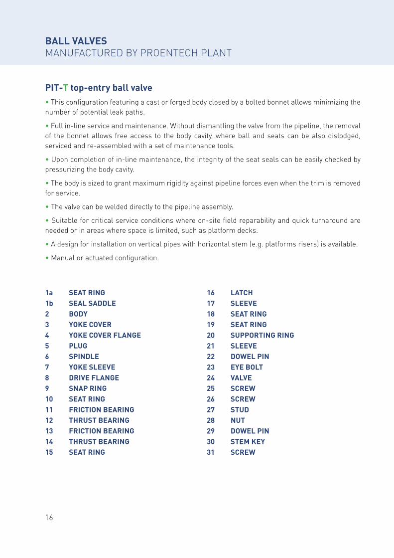
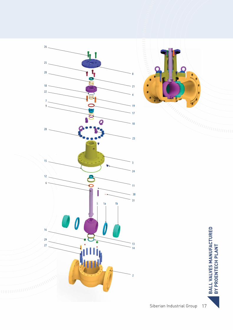
PIT-T top-entry ball valve• This configuration featuring a cast or forged body closed by a bolted bonnet allows minimizing the number of potential leak paths.
• Full in-line service and maintenance. Without dismantling the valve from the pipeline, the removal of the bonnet allows free access to the body cavity, where ball and seats can be also dislodged, serviced and re-assembled with a set of maintenance tools.
• Upon completion of in-line maintenance, the integrity of the seat seals can be easily checked by pressurizing the body cavity.
• The body is sized to grant maximum rigidity against pipeline forces even when the trim is removed for service.
• The valve can be welded directly to the pipeline assembly.
• Suitable for critical service conditions where on-site field reparability and quick turnaround are needed or in areas where space is limited, such as platform decks.
• A design for installation on vertical pipes with horizontal stem (e.g. platforms risers) is available.
• Manual or actuated configuration.
1a SEAT RING1b SEAL SADDLE2 BODY3 YOKE COVER4 YOKE COVER FLANGE5 PLUG6 SPINDLE7 YOKE SLEEVE8 DRIVE FLANGE9 SNAP RING10 SEAT RING11 FRICTION BEARING12 THRUST BEARING13 FRICTION BEARING14 THRUST BEARING15 SEAT RING
16 LATCH17 SLEEVE18 SEAT RING19 SEAT RING20 SUPPORTING RING21 SLEEVE22 DOWEL PIN23 EYE BOLT24 VALVE25 SCREW26 SCREW27 STUD28 NUT29 DOWEL PIN 30 STEM KEY31 SCREW
17Siberian Industrial Group
2
27
29
6
12
15
28
9
7
22
18
20
25
26
16
1413
315
30
1а 1b
11
24
3
23
10
17
19
4
21
8
BA
LL V
ALV
ES M
AN
UFA
CTU
RED
B
Y PR
OEN
TECH
PLA
NT
18
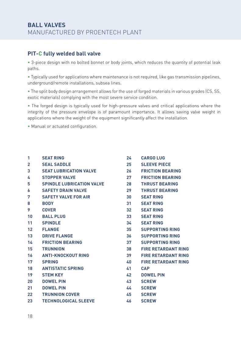
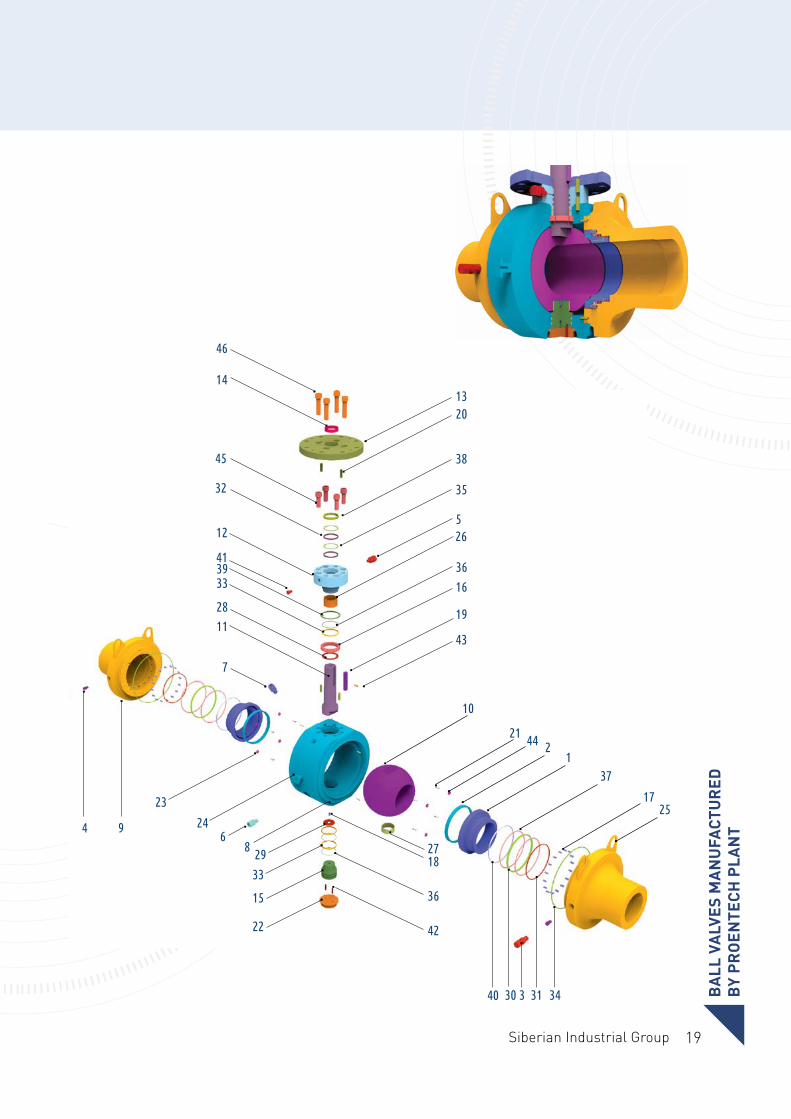
PIT-C fully welded ball valve• 3-piece design with no bolted bonnet or body joints, which reduces the quantity of potential leak paths.
• Typically used for applications where maintenance is not required, like gas transmission pipelines, underground/remote installations, subsea lines.
• The split body design arrangement allows for the use of forged materials in various grades (CS, SS, exotic materials) complying with the most severe service condition.
• The forged design is typically used for high-pressure valves and critical applications where the integrity of the pressure envelope is of paramount importance. It allows saving valve weight in applications where the weight of the equipment significantly affect the installation.
• Manual or actuated configuration.
BALL VALVES MANUFACTURED BY PROENTECH PLANT
1 SEAT RING2 SEAL SADDLE3 SEAT LUBRICATION VALVE4 STOPPER VALVE5 SPINDLE LUBRICATION VALVE 6 SAFETY DRAIN VALVE7 SAFETY VALVE FOR AIR8 BODY9 COVER10 BALL PLUG11 SPINDLE12 FLANGE13 DRIVE FLANGE14 FRICTION BEARING15 TRUNNION 16 ANTI-KNOCKOUT RING17 SPRING18 ANTISTATIC SPRING19 STEM KEY20 DOWEL PIN21 DOWEL PIN22 TRUNNION COVER23 TECHNOLOGICAL SLEEVE
24 CARGO LUG25 SLEEVE PIECE26 FRICTION BEARING27 FRICTION BEARING28 THRUST BEARING29 THRUST BEARING30 SEAT RING31 SEAT RING32 SEAT RING33 SEAT RING34 SEAT RING35 SUPPORTING RING36 SUPPORTING RING37 SUPPORTING RING38 FIRE RETARDANT RING39 FIRE RETARDANT RING40 FIRE RETARDANT RING41 CAP42 DOWEL PIN43 SCREW 44 SCREW45 SCREW46 SCREW
19Siberian Industrial Group
43
10
21 44 21
17
343133040
3 4 9
23
246
8 29
33
15
22
2718
36
42
37
25
7
1128
3339
19
16
36
265
41
12
45
14
46
32 35
38
2013
BA
LL V
ALV
ES M
AN
UFA
CTU
RED
B
Y PR
OEN
TECH
PLA
NT
20
Special applications
HIGH TEMPERATURE FROM +220 °C TO +625 °C
• Side-entry and top-entry configurations
• Cast or forged construction
• Extended bonnet for insulation allowance
• Metal and graphite seals
• Built-in fire safe design
• Adjustable stem packing with live load which guarantees performance also under thermal cycles
• Anti-friction coating on seating surfaces for torque requirements
• Materials compliant with stricter requirements
• Selection of hard facing technologies (ENP, CCC, NiSic) suitable for any service
LOW TEMPERATURE DOWN TO -196 °C
• Side-entry and top-entry configurations
• Cast or forged construction
• Extended bonnet with vapor space to maintain the stem packing within the suitable temperatureт range
• Enhanced seat and seal design to guarantee leak tightness
• Anti-friction coating on seating surfaces for torque requirements
• Materials compliant with stricter requirements
• Additional inspection and testing
HABITAT WITH A HIGH CONTENT OF HYDROGEN SULPHIDE
• Side-entry configurations
• Forged construction
• Body closure with overlaying in the contact areas of seals
• Metal and graphite seals
• Built-in fire safe design
• Anti-friction coating on seating surfaces for torque requirements
• Materials compatible with the requirements of CKBA 052-2008; NACE MR0175; ISO 15156
• Selection of hard facing technologies (ENP, CCC, NiSic) suitable for any service
BALL VALVES MANUFACTURED BY PROENTECH PLANT
21Siberian Industrial Group
BALL VALVES MANUFACTURED BY PROENTECH PLANTDESIGN FEATURES
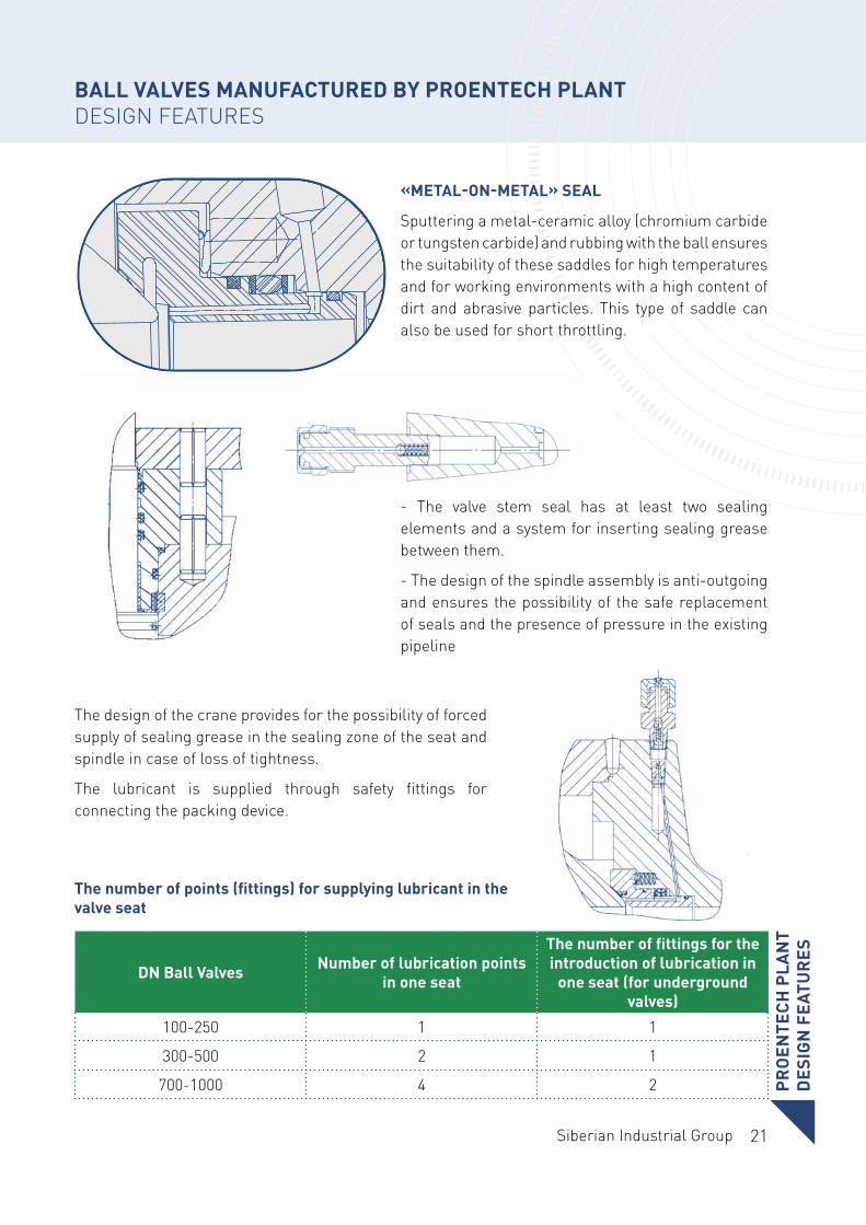
The number of points (fittings) for supplying lubricant in the valve seat
The design of the crane provides for the possibility of forced supply of sealing grease in the sealing zone of the seat and spindle in case of loss of tightness.
The lubricant is supplied through safety fittings for connecting the packing device.
«METAL-ON-METAL» SEAL
Sputtering a metal-ceramic alloy (chromium carbide or tungsten carbide) and rubbing with the ball ensures the suitability of these saddles for high temperatures and for working environments with a high content of dirt and abrasive particles. This type of saddle can also be used for short throttling.
- The valve stem seal has at least two sealing elements and a system for inserting sealing grease between them.
- The design of the spindle assembly is anti-outgoing and ensures the possibility of the safe replacement of seals and the presence of pressure in the existing pipeline
PRO
ENTE
CH P
LAN
TD
ESIG
N F
EATU
RES
DN Ball Valves Number of lubrication points in one seat
The number of fittings for the introduction of lubrication in
one seat (for underground valves)
100-250 1 1
300-500 2 1
700-1000 4 2
22
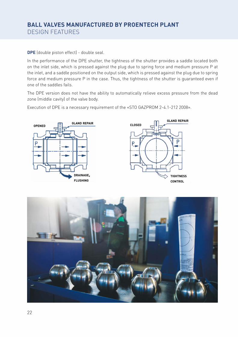
openedgland repair
drainage,flushing
gland repairclosed
tightness
control
BALL VALVES MANUFACTURED BY PROENTECH PLANTDESIGN FEATURES
DPE (double piston effect) - double seal.
In the performance of the DPE shutter, the tightness of the shutter provides a saddle located both on the inlet side, which is pressed against the plug due to spring force and medium pressure P at the inlet, and a saddle positioned on the output side, which is pressed against the plug due to spring force and medium pressure P in the case. Thus, the tightness of the shutter is guaranteed even if one of the saddles fails.
The DPE version does not have the ability to automatically relieve excess pressure from the dead zone (middle cavity) of the valve body.
Execution of DPE is a necessary requirement of the «STO GAZPROM 2-4.1-212 2008».
23Siberian Industrial Group
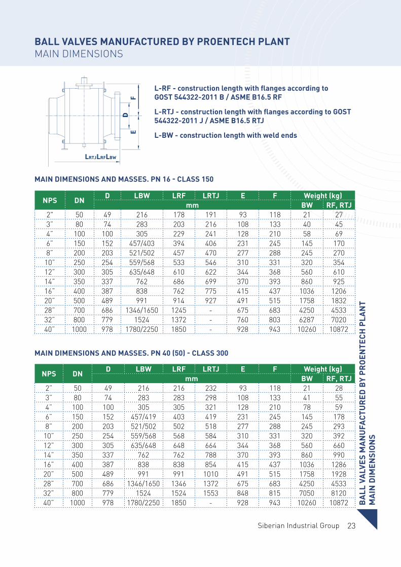
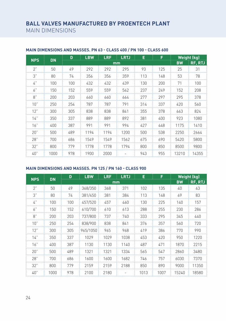
L-RF - construction length with flanges according to GOST 544322-2011 B / ASME B16.5 RF
L-RTJ - construction length with flanges according to GOST 544322-2011 J / ASME B16.5 RTJ
L-BW - construction length with weld ends
MAIN DIMENSIONS AND MASSES. PN 16 - CLASS 150
MAIN DIMENSIONS AND MASSES. PN 40 (50) - CLASS 300
BALL VALVES MANUFACTURED BY PROENTECH PLANTMAIN DIMENSIONS
BA
LL V
ALV
ES M
AN
UFA
CTU
RED
BY
PRO
ENTE
CH P
LAN
T M
AIN
DIM
ENSI
ON
S
NPS DND LBW LRF LRTJ E F Weight (kg)
mm BW RF, RTJ2" 50 49 216 178 191 93 118 21 273” 80 74 283 203 216 108 133 40 454” 100 100 305 229 241 128 210 58 696” 150 152 457/403 394 406 231 245 145 1708” 200 203 521/502 457 470 277 288 245 270
10” 250 254 559/568 533 546 310 331 320 35412” 300 305 635/648 610 622 344 368 560 61014” 350 337 762 686 699 370 393 860 92516” 400 387 838 762 775 415 437 1036 120620” 500 489 991 914 927 491 515 1758 183228” 700 686 1346/1650 1245 - 675 683 4250 453332” 800 779 1524 1372 - 760 803 6287 702040” 1000 978 1780/2250 1850 - 928 943 10260 10872
NPS DND LBW LRF LRTJ E F Weight (kg)
mm BW RF, RTJ2” 50 49 216 216 232 93 118 21 283” 80 74 283 283 298 108 133 41 554” 100 100 305 305 321 128 210 78 596” 150 152 457/419 403 419 231 245 145 1788” 200 203 521/502 502 518 277 288 245 293
10” 250 254 559/568 568 584 310 331 320 39212” 300 305 635/648 648 664 344 368 560 66014” 350 337 762 762 788 370 393 860 99016” 400 387 838 838 854 415 437 1036 128620” 500 489 991 991 1010 491 515 1758 192828” 700 686 1346/1650 1346 1372 675 683 4250 453332” 800 779 1524 1524 1553 848 815 7050 812040” 1000 978 1780/2250 1850 - 928 943 10260 10872
24
MAIN DIMENSIONS AND MASSES. PN 63 - CLASS 400 / PN 100 - CLASS 600
MAIN DIMENSIONS AND MASSES. PN 125 / PN 160 - CLASS 900
BALL VALVES MANUFACTURED BY PROENTECH PLANTMAIN DIMENSIONS
NPS DND LBW LRF LRTJ E F Weight (kg)
mm BW RF, RTJ2” 50 49 292 292 295 93 125 25 31
3” 80 74 356 356 359 113 148 53 78
4” 100 100 432 432 439 130 200 71 100
6” 150 152 559 559 562 237 249 152 208
8” 200 203 660 660 664 277 297 295 378
10” 250 254 787 787 791 314 337 420 560
12” 300 305 838 838 841 355 378 663 824
14” 350 337 889 889 892 381 400 923 1080
16” 400 387 991 991 994 427 448 1175 1410
20” 500 489 1194 1194 1200 500 538 2250 2664
28” 700 686 1549 1549 1562 675 690 5420 5800
32” 800 779 1778 1778 1794 800 850 8500 9800
40” 1000 978 1900 2000 - 943 955 13210 14355
NPS DND LBW LRF LRTJ E F Weight (kg)
mm BW RF, RTJ2” 50 49 368/350 368 371 102 135 40 63
3” 80 74 381/450 381 384 113 148 69 83
4” 100 100 457/520 457 460 130 225 140 157
6” 150 152 610/700 610 613 288 255 230 286
8” 200 203 737/800 737 740 333 295 345 440
10” 250 254 838/900 838 841 376 357 560 720
12” 300 305 965/1050 965 968 419 386 770 990
14” 350 337 1029 1029 1038 453 420 950 1220
16” 400 387 1130 1130 1140 487 471 1870 2215
20” 500 489 1321 1321 1334 565 547 2860 3480
28” 700 686 1600 1600 1682 746 757 6030 7370
32” 800 779 2159 2159 2188 850 890 9000 11350
40” 1000 978 2100 2180 - 1013 1007 15240 18580
25Siberian Industrial Group
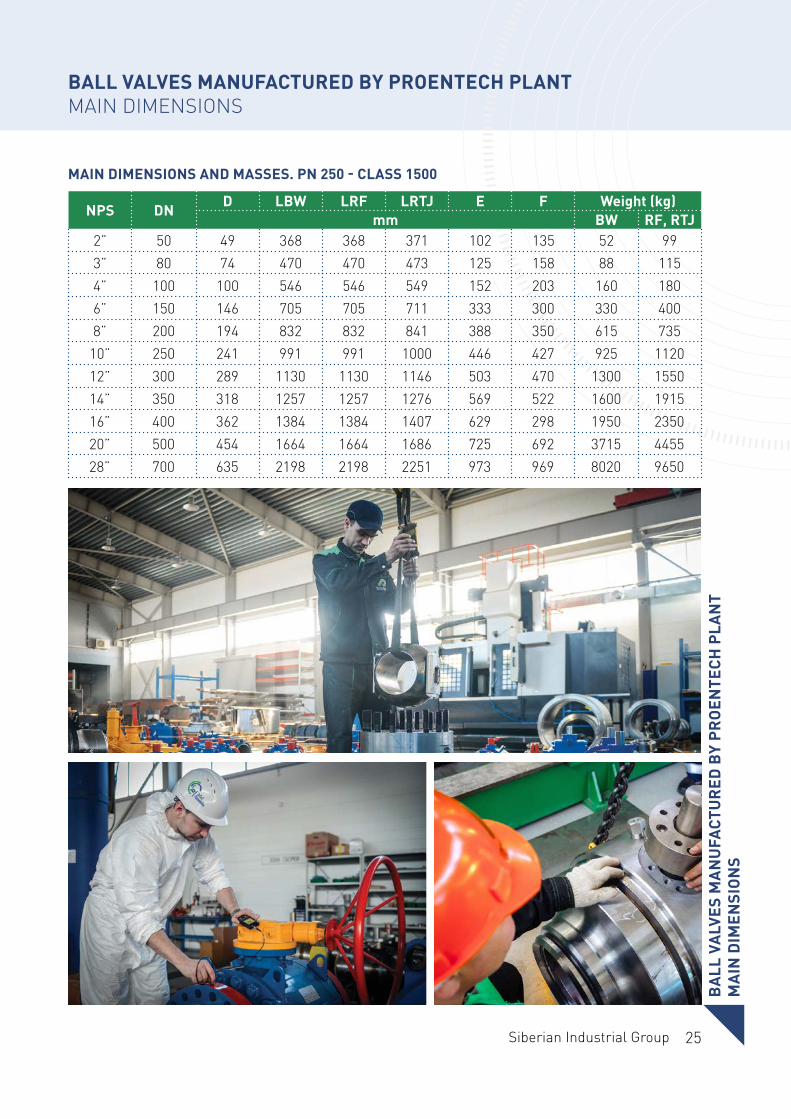
MAIN DIMENSIONS AND MASSES. PN 250 - CLASS 1500
BALL VALVES MANUFACTURED BY PROENTECH PLANTMAIN DIMENSIONS
BA
LL V
ALV
ES M
AN
UFA
CTU
RED
BY
PRO
ENTE
CH P
LAN
TM
AIN
DIM
ENSI
ON
S
NPS DND LBW LRF LRTJ E F Weight (kg)
mm BW RF, RTJ2” 50 49 368 368 371 102 135 52 993” 80 74 470 470 473 125 158 88 1154” 100 100 546 546 549 152 203 160 1806” 150 146 705 705 711 333 300 330 4008” 200 194 832 832 841 388 350 615 735
10” 250 241 991 991 1000 446 427 925 112012” 300 289 1130 1130 1146 503 470 1300 155014” 350 318 1257 1257 1276 569 522 1600 191516” 400 362 1384 1384 1407 629 298 1950 235020” 500 454 1664 1664 1686 725 692 3715 445528” 700 635 2198 2198 2251 973 969 8020 9650
26
BALL VALVES MANUFACTURED BY PROENTECH PLANTQUALITY CONTROL AND TESTING
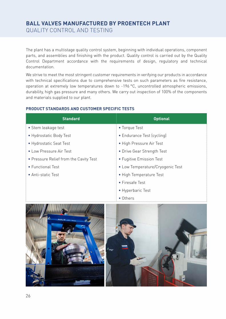
The plant has a multistage quality control system, beginning with individual operations, component parts, and assemblies and finishing with the product. Quality control is carried out by the Quality Control Department accordance with the requirements of design, regulatory and technical documentation.
We strive to meet the most stringent customer requirements in verifying our products in accordance with technical specifications due to comprehensive tests on such parameters as fire resistance, operation at extremely low temperatures down to -196 °C, uncontrolled atmospheric emissions, durability, high gas pressure and many others. We carry out inspection of 100% of the components and materials supplied to our plant.
Standard Optional
• Stem leakage test
• Hydrostatic Body Test
• Hydrostatic Seat Test
• Low Pressure Air Test
• Pressure Relief from the Cavity Test
• Functional Test
• Anti-static Test
• Torque Test
• Endurance Test (cycling)
• High Pressure Air Test
• Drive Gear Strength Test
• Fugitive Emission Test
• Low Temperature/Cryogenic Test
• High Temperature Test
• Firesafe Test
• Hyperbaric Test
• Others
PRODUCT STANDARDS AND CUSTOMER SPECIFIC TESTS
27Siberian Industrial Group
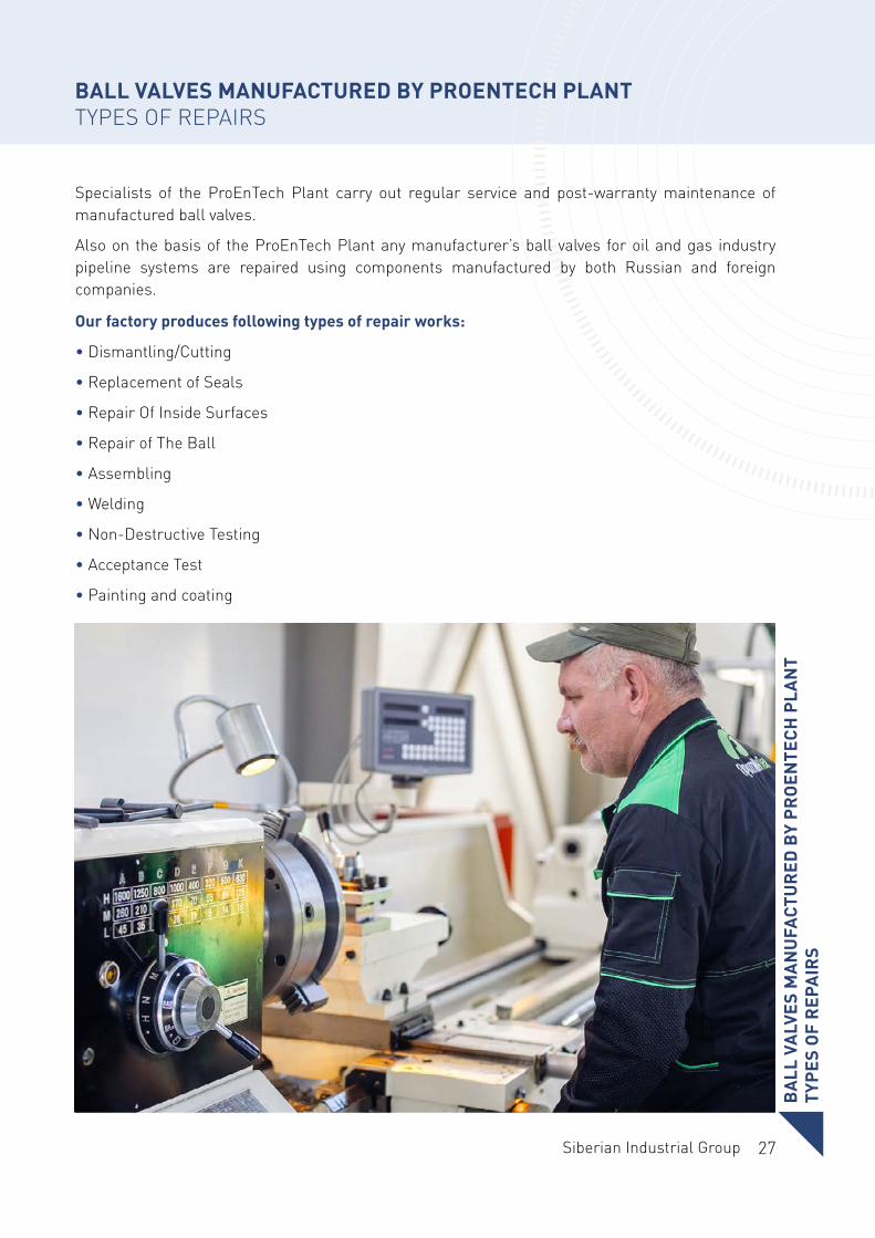
BALL VALVES MANUFACTURED BY PROENTECH PLANTTYPES OF REPAIRS
Specialists of the ProEnTech Plant carry out regular service and post-warranty maintenance of manufactured ball valves.
Also on the basis of the ProEnTech Plant any manufacturer’s ball valves for oil and gas industry pipeline systems are repaired using components manufactured by both Russian and foreign companies.
Our factory produces following types of repair works:
• Dismantling/Cutting
• Replacement of Seals
• Repair Of Inside Surfaces
• Repair of The Ball
• Assembling
• Welding
• Non-Destructive Testing
• Acceptance Test
• Painting and coating
BA
LL V
ALV
ES M
AN
UFA
CTU
RED
BY
PRO
ENTE
CH P
LAN
TTY
PES
OF
REP
AIR
S
28
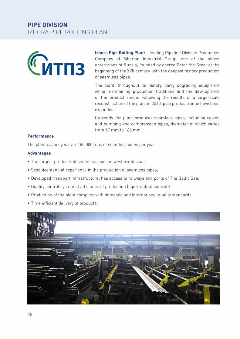
Performance
The plant capacity is over 180,000 tons of seamless pipes per year.
Advantages
• The largest producer of seamless pipes in western Russia;
• Sesquicentennial experience in the production of seamless pipes;
• Developed transport infrastructure: has access to railways and ports of The Baltic Sea;
• Quality control system at all stages of production (input-output control);
• Production of the plant complies with domestic and international quality standards;
• Time efficient delivery of products;
PIPE DIVISIONIZHORA PIPE ROLLING PLANT
Izhora Pipe Rolling Plant – leading Pipeline Division Production Company of Siberian Industrial Group, one of the oldest enterprises of Russia, founded by decree Peter the Great at the beginning of the XVII century, with the deepest history production of seamless pipes.
The plant, throughout its history, carry upgrading equipment while maintaining production traditions and the development of the product range. Following the results of a large-scale reconstruction of the plant in 2010, pipe product range have been expanded.
Currently, the plant produces seamless pipes, including casing and pumping and compression pipes, diameter of which varies from 57 mm to 168 mm.
29Siberian Industrial Group
PIPE DIVISIONIZHORA PIPE ROLLING PLANT
IZH
OR
A P
IPE
RO
LLIN
G P
LAN
T
• Complex deliveries of pipe and related products on favorable terms;
• Targeted work with customers, individual approach.
Advantages of seamless steel pipes
• High and low temperature resistant
• Suitable for use in high-pressure conditions.
• Long service life
• High product strength
• Resistance to mechanical stress
• Corrosion Resistance
Factory Products
• Seamless hot-deformed steel pipes (GOST 8731- 74, GOST 8732- 78);
• Seamless hot-deformed steel pipes (GOST 32528-2013);
• Cold-resistant seamless steel pipes for gas pipelines of gas-lift oil production systems and arrangement of gas fields (TU 14-3R-1128-2007);
• Seamless steel pipes for boiler plants and pipelines (TU 14-3-190-2004);
• Casing pipes and couplings for them (GOST 632-80);
• Pumping and compression pipes and couplings for them (GOST 633-80);
• Steel pipes used as casing or pumping and compression pipes for wells in the oil and gas industry (GOST 31446-2017);
• Seamless steel hot deformed pumping and compression pipes and couplings for them, pipe billet for the manufacture of pumping and compression pipes and couplings (TU 14-3R-81-2005).
30
CERTIFICATES AND DOCUMENTATIONIZHORA PIPE ROLLING PLANT
31Siberian Industrial Group
CER
TIFI
CATE
S A
ND
DO
CUM
ENTA
TIO
NIZ
HO
RA
PIP
E R
OLL
ING
PLA
NT
CERTIFICATES AND DOCUMENTATIONIZHORA PIPE ROLLING PLANT
32
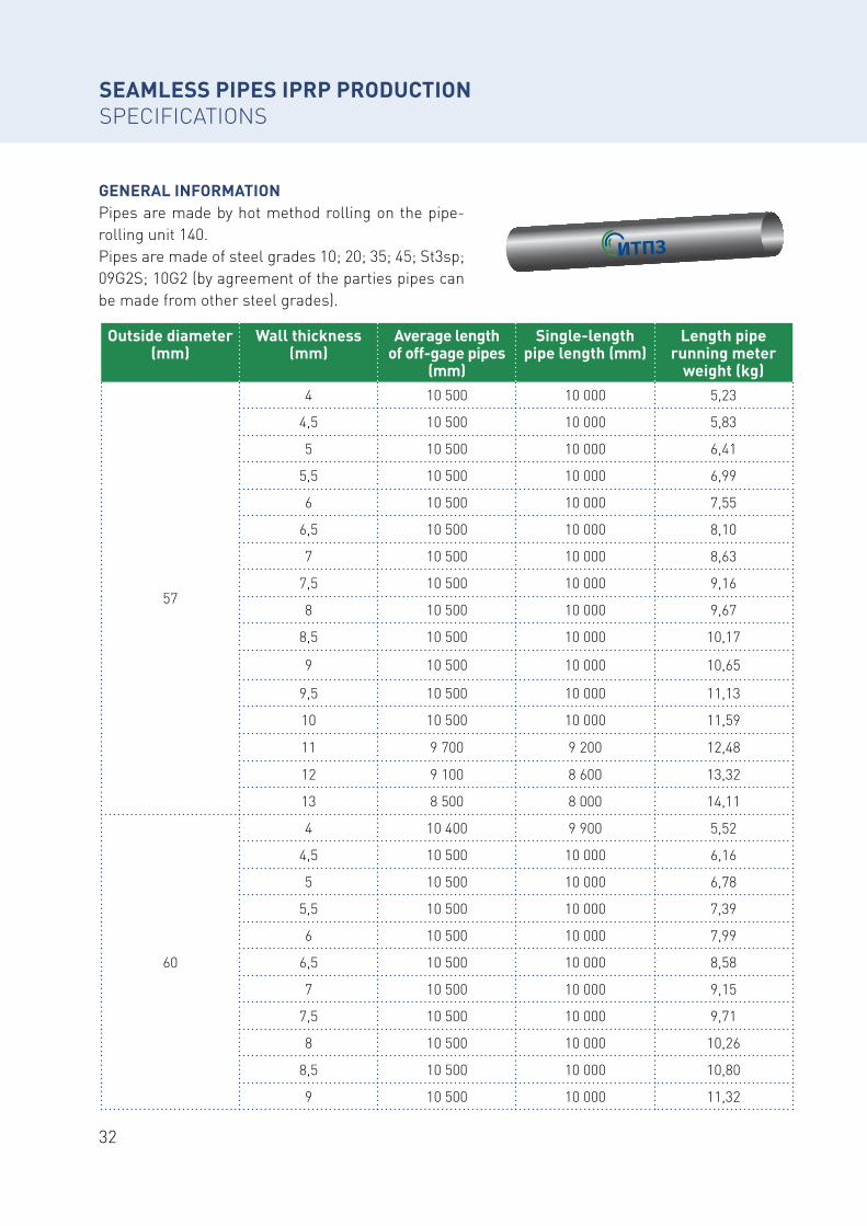
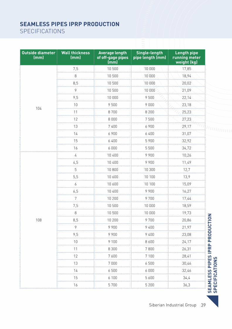
SEAMLESS PIPES IPRP PRODUCTIONSPECIFICATIONS
GENERAL INFORMATIONPipes are made by hot method rolling on the pipe-rolling unit 140.Pipes are made of steel grades 10; 20; 35; 45; St3sp; 09G2S; 10G2 (by agreement of the parties pipes can be made from other steel grades).
Outside diameter (mm)
Wall thickness (mm)
Average length of off-gage pipes
(mm)
Single-length pipe length (mm)
Length pipe running meter
weight (kg)
57
4 10 500 10 000 5,23
4,5 10 500 10 000 5,83
5 10 500 10 000 6,41
5,5 10 500 10 000 6,99
6 10 500 10 000 7,55
6,5 10 500 10 000 8,10
7 10 500 10 000 8,63
7,5 10 500 10 000 9,16
8 10 500 10 000 9,67
8,5 10 500 10 000 10,17
9 10 500 10 000 10,65
9,5 10 500 10 000 11,13
10 10 500 10 000 11,59
11 9 700 9 200 12,48
12 9 100 8 600 13,32
13 8 500 8 000 14,11
60
4 10 400 9 900 5,52
4,5 10 500 10 000 6,16
5 10 500 10 000 6,78
5,5 10 500 10 000 7,39
6 10 500 10 000 7,99
6,5 10 500 10 000 8,58
7 10 500 10 000 9,15
7,5 10 500 10 000 9,71
8 10 500 10 000 10,26
8,5 10 500 10 000 10,80
9 10 500 10 000 11,32

33Siberian Industrial Group
Outside diameter (mm)
Wall thickness (mm)
Average length of off-gage pipes
(mm)
Single-length pipe length (mm)
Length pipe running meter
weight (kg)
60
9,5 10 300 9 800 11,83
10 9 900 9 400 12,33
11 9 100 8 600 13,29
12 8 400 7 900 14,21
13 7 900 7 400 15,07
14 7 400 6 900 15,88
60,3
4 10 500 10 000 5,55
4,5 10 500 10 000 6,19
5 10 400 9 900 6,82
5,5 10 400 9 900 7,43
6 10 500 10 000 8,03
6,5 10 500 10 000 8,62
7 10 500 10 000 9,20
7,5 10 500 10 000 9,76
8 10 500 10 000 10,32
8,5 10 500 10 000 10,86
9 10 500 10 000 11,38
9,5 10 300 9 800 11,90
10 9 800 9 300 12,40
11 9 000 8 500 13,37
12 8 400 7 900 14,29
13 7 800 7 300 15,16
14 7 400 6 900 15,98
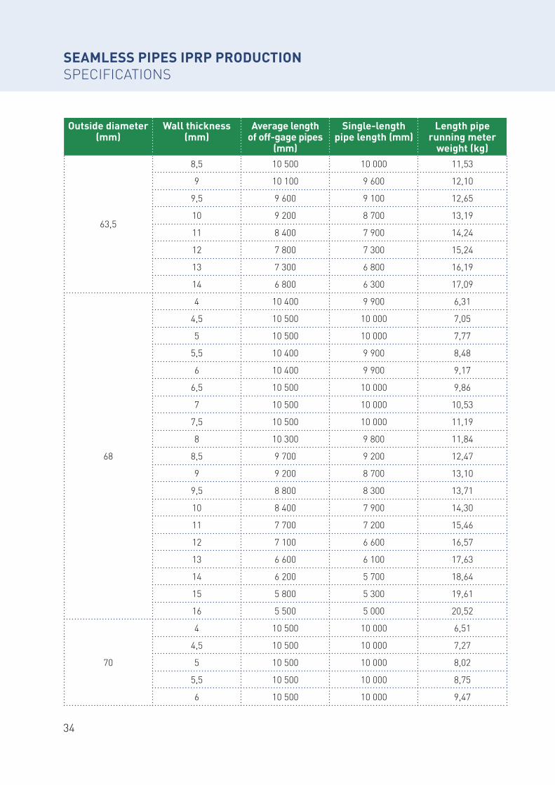
63,5
4 10 400 9 900 5,87
4,5 10 500 10 000 6,55
5 10 500 10 000 7,21
5,5 10 400 9 900 7,87
6 10 500 10 000 8,51
6,5 10 500 10 000 9,14
7 10 500 10 000 9,75
7,5 10 500 10 000 10,36
8 10 500 10 000 10,95
SEAMLESS PIPES IPRP PRODUCTIONSPECIFICATIONS
SEA
MLE
SS P
IPES
IPR
P PR
OD
UCT
ION
SPEC
IFIC
ATIO
NS
34
Outside diameter (mm)
Wall thickness (mm)
Average length of off-gage pipes
(mm)
Single-length pipe length (mm)
Length pipe running meter
weight (kg)
63,5
8,5 10 500 10 000 11,53
9 10 100 9 600 12,10
9,5 9 600 9 100 12,65
10 9 200 8 700 13,19
11 8 400 7 900 14,24
12 7 800 7 300 15,24
13 7 300 6 800 16,19
14 6 800 6 300 17,09
68
4 10 400 9 900 6,31
4,5 10 500 10 000 7,05
5 10 500 10 000 7,77
5,5 10 400 9 900 8,48
6 10 400 9 900 9,17
6,5 10 500 10 000 9,86
7 10 500 10 000 10,53
7,5 10 500 10 000 11,19
8 10 300 9 800 11,84
8,5 9 700 9 200 12,47
9 9 200 8 700 13,10
9,5 8 800 8 300 13,71
10 8 400 7 900 14,30
11 7 700 7 200 15,46
12 7 100 6 600 16,57
13 6 600 6 100 17,63
14 6 200 5 700 18,64
15 5 800 5 300 19,61
16 5 500 5 000 20,52
70
4 10 500 10 000 6,51
4,5 10 500 10 000 7,27
5 10 500 10 000 8,02
5,5 10 500 10 000 8,75
6 10 500 10 000 9,47
SEAMLESS PIPES IPRP PRODUCTIONSPECIFICATIONS
35Siberian Industrial Group
Outside diameter (mm)
Wall thickness (mm)
Average length of off-gage pipes
(mm)
Single-length pipe length (mm)
Length pipe running meter
weight (kg)
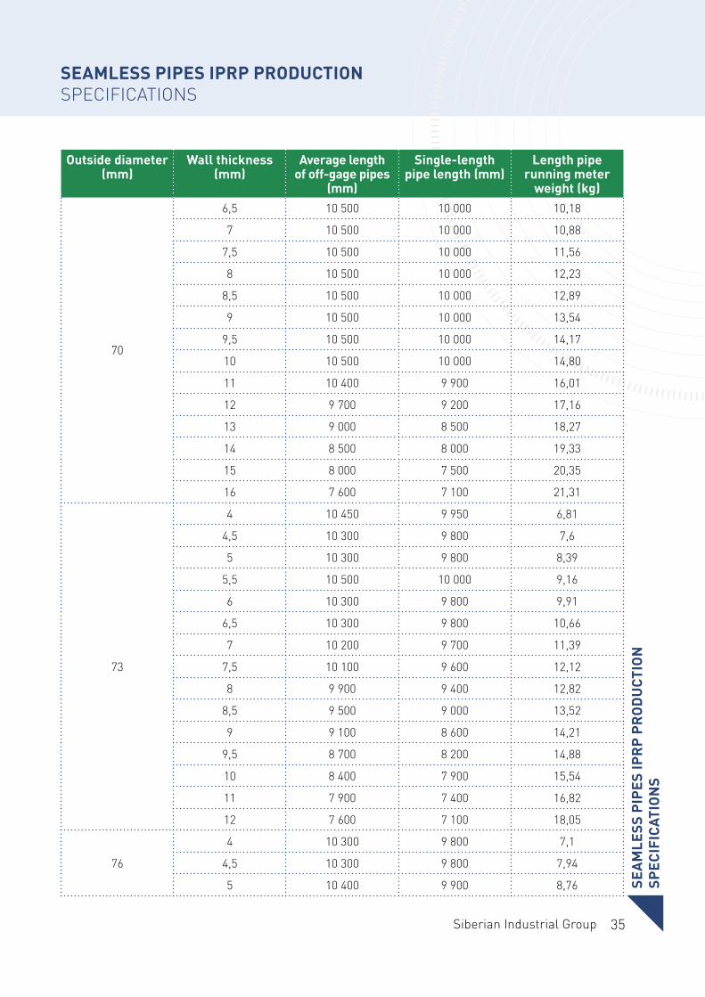
70
6,5 10 500 10 000 10,18
7 10 500 10 000 10,88
7,5 10 500 10 000 11,56
8 10 500 10 000 12,23
8,5 10 500 10 000 12,89
9 10 500 10 000 13,54
9,5 10 500 10 000 14,17
10 10 500 10 000 14,80
11 10 400 9 900 16,01
12 9 700 9 200 17,16
13 9 000 8 500 18,27
14 8 500 8 000 19,33
15 8 000 7 500 20,35
16 7 600 7 100 21,31
73
4 10 450 9 950 6,81
4,5 10 300 9 800 7,6
5 10 300 9 800 8,39
5,5 10 500 10 000 9,16
6 10 300 9 800 9,91
6,5 10 300 9 800 10,66
7 10 200 9 700 11,39
7,5 10 100 9 600 12,12
8 9 900 9 400 12,82
8,5 9 500 9 000 13,52
9 9 100 8 600 14,21
9,5 8 700 8 200 14,88
10 8 400 7 900 15,54
11 7 900 7 400 16,82
12 7 600 7 100 18,05
76
4 10 300 9 800 7,1
4,5 10 300 9 800 7,94
5 10 400 9 900 8,76
SEAMLESS PIPES IPRP PRODUCTIONSPECIFICATIONS
SEA
MLE
SS P
IPES
IPR
P PR
OD
UCT
ION
SPEC
IFIC
ATIO
NS
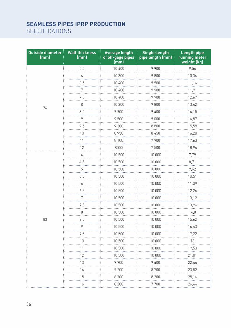
36
Outside diameter (mm)
Wall thickness (mm)
Average length of off-gage pipes
(mm)
Single-length pipe length (mm)
Length pipe running meter
weight (kg)
76
5,5 10 400 9 900 9,56
6 10 300 9 800 10,36
6,5 10 400 9 900 11,14
7 10 400 9 900 11,91
7,5 10 400 9 900 12,67
8 10 300 9 800 13,42
8,5 9 900 9 400 14,15
9 9 500 9 000 14,87
9,5 9 300 8 800 15,58
10 8 950 8 450 16,28
11 8 400 7 900 17,63
12 8000 7 500 18,94
83
4 10 500 10 000 7,79
4,5 10 500 10 000 8,71
5 10 500 10 000 9,62
5,5 10 500 10 000 10,51
6 10 500 10 000 11,39
6,5 10 500 10 000 12,26
7 10 500 10 000 13,12
7,5 10 500 10 000 13,96
8 10 500 10 000 14,8
8,5 10 500 10 000 15,62
9 10 500 10 000 16,43
9,5 10 500 10 000 17,22
10 10 500 10 000 18
11 10 500 10 000 19,53
12 10 500 10 000 21,01
13 9 900 9 400 22,44
14 9 200 8 700 23,82
15 8 700 8 200 25,16
16 8 200 7 700 26,44
SEAMLESS PIPES IPRP PRODUCTIONSPECIFICATIONS

37Siberian Industrial Group
Outside diameter (mm)
Wall thickness (mm)
Average length of off-gage pipes
(mm)
Single-length pipe length (mm)
Length pipe running meter
weight (kg)
89
4 10 400 9 900 8,39
4,5 10 500 10 000 9,38
5 10 600 10 100 10,36
5,5 10 600 10 100 11,33
6 10 600 10 100 12,28
6,5 10 600 10 100 13,23
7 10 600 10 100 14,16
7,5 10 600 10 100 15,07
8 10 600 10 100 15,98
8,5 10 600 10 100 16,88
9 10 800 10 300 17,76
9,5 10 500 10 000 18,63
10 10 500 10 000 19,48
11 10 200 9 700 21,16
12 9 700 9 200 22,7
13 9 000 8 500 24,37
14 8 400 7 900 25,9
15 7 900 7 400 27,37
16 7 500 7 000 28,81
95
4 10 500 10 000 8,98
4,5 10 500 10 000 10,04
5 10 500 10 000 11,1
5,5 10 500 10 000 12,14
6 10 500 10 000 13,17
6,5 10 500 10 000 14,19
7 10 500 10 000 15,19
7,5 10 500 10 000 16,18
8 10 500 10 000 17,16
8,5 10 500 10 000 18,13
9 10 500 10 000 19,09
9,5 10 500 10 000 20,03
10 10 500 10 000 20,96
SEAMLESS PIPES IPRP PRODUCTIONSPECIFICATIONS
SEA
MLE
SS P
IPES
IPR
P PR
OD
UCT
ION
SPEC
IFIC
ATIO
NS

38
Outside diameter (mm)
Wall thickness (mm)
Average length of off-gage pipes
(mm)
Single-length pipe length (mm)
Length pipe running meter
weight (kg)
95
11 9 700 9 200 22,79
12 8 900 8 400 24,56
13 8 300 7 800 26,29
14 7 700 7 200 27,97
15 7 200 6 700 29,59
16 6 800 6 300 31,17
102
4 9 900 9 400 9,67
4,5 10 100 9 600 10,82
5 9 950 9 450 11,96
5,5 9 900 9 400 13,09
6 9 900 9 400 14,21
6,5 10 000 9 500 15,31
7 10 000 9 500 16,4
7,5 10 000 9 500 17,48
8 10 000 9 500 18,55
8,5 10 000 9 500 19,6
9 10 000 9 500 20,64
9,5 10 000 9 500 21,67
10 9 750 9 250 22,69
11 8 900 8 400 24,69
12 8 200 7 700 26,63
13 7 550 7 050 28,53
14 7 000 6 500 30,38
15 6 600 6 100 32,18
16 6 200 5 700 33,93
104
4 10 500 10 000 9,86
4,5 10 500 10 000 11,04
5 10 500 10 000 12,21
5,5 10 500 10 000 13,36
6 10 500 10 000 14,5
6,5 10 500 10 000 15,63
7 10 500 10 000 16,74
SEAMLESS PIPES IPRP PRODUCTIONSPECIFICATIONS
39Siberian Industrial Group
Outside diameter (mm)
Wall thickness (mm)
Average length of off-gage pipes
(mm)
Single-length pipe length (mm)
Length pipe running meter
weight (kg)
104
7,5 10 500 10 000 17,85
8 10 500 10 000 18,94
8,5 10 500 10 000 20,02
9 10 500 10 000 21,09
9,5 10 000 9 500 22,14
10 9 500 9 000 23,18
11 8 700 8 200 25,23
12 8 000 7 500 27,23
13 7 400 6 900 29,17
14 6 900 6 400 31,07
15 6 400 5 900 32,92
16 6 000 5 500 34,72
108
4 10 400 9 900 10,26
4,5 10 400 9 900 11,49
5 10 800 10 300 12,7
5,5 10 600 10 100 13,9
6 10 600 10 100 15,09
6,5 10 400 9 900 16,27
7 10 200 9 700 17,44
7,5 10 500 10 000 18,59
8 10 500 10 000 19,73
8,5 10 200 9 700 20,86
9 9 900 9 400 21,97
9,5 9 900 9 400 23,08
10 9 100 8 600 24,17
11 8 300 7 800 26,31
12 7 600 7 100 28,41
13 7 000 6 500 30,46
14 6 500 6 000 32,46
15 6 100 5 600 34,4
16 5 700 5 200 36,3
SEAMLESS PIPES IPRP PRODUCTIONSPECIFICATIONS
SEA
MLE
SS P
IPES
IPR
P PR
OD
UCT
ION
SPEC
IFIC
ATIO
NS
40
Outside diameter (mm)
Wall thickness (mm)
Average length of off-gage pipes
(mm)
Single-length pipe length (mm)
Length pipe running meter
weight (kg)
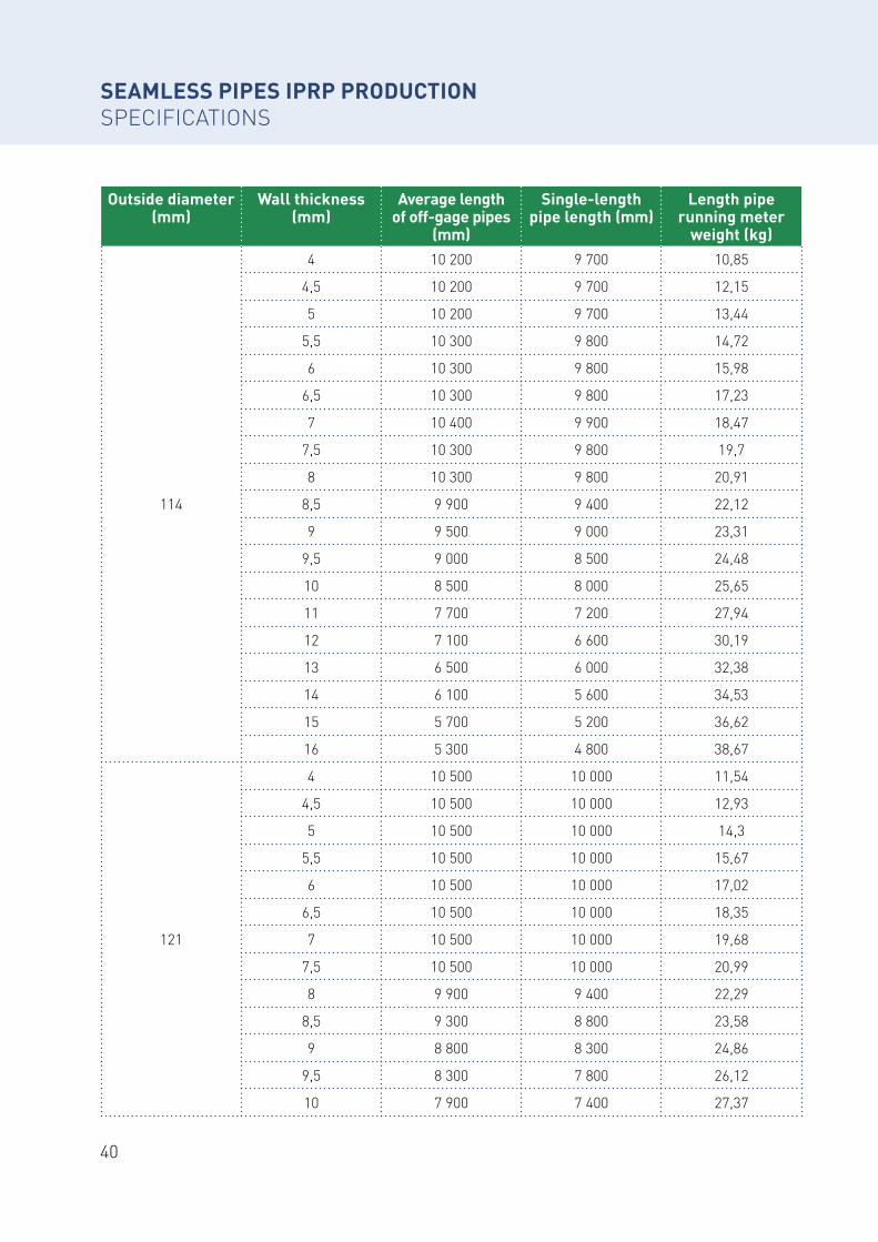
114
4 10 200 9 700 10,85
4,5 10 200 9 700 12,15
5 10 200 9 700 13,44
5,5 10 300 9 800 14,72
6 10 300 9 800 15,98
6,5 10 300 9 800 17,23
7 10 400 9 900 18,47
7,5 10 300 9 800 19,7
8 10 300 9 800 20,91
8,5 9 900 9 400 22,12
9 9 500 9 000 23,31
9,5 9 000 8 500 24,48
10 8 500 8 000 25,65
11 7 700 7 200 27,94
12 7 100 6 600 30,19
13 6 500 6 000 32,38
14 6 100 5 600 34,53
15 5 700 5 200 36,62
16 5 300 4 800 38,67
121
4 10 500 10 000 11,54
4,5 10 500 10 000 12,93
5 10 500 10 000 14,3
5,5 10 500 10 000 15,67
6 10 500 10 000 17,02
6,5 10 500 10 000 18,35
7 10 500 10 000 19,68
7,5 10 500 10 000 20,99
8 9 900 9 400 22,29
8,5 9 300 8 800 23,58
9 8 800 8 300 24,86
9,5 8 300 7 800 26,12
10 7 900 7 400 27,37
SEAMLESS PIPES IPRP PRODUCTIONSPECIFICATIONS
41Siberian Industrial Group
Outside diameter (mm)
Wall thickness (mm)
Average length of off-gage pipes
(mm)
Single-length pipe length (mm)
Length pipe running meter
weight (kg)
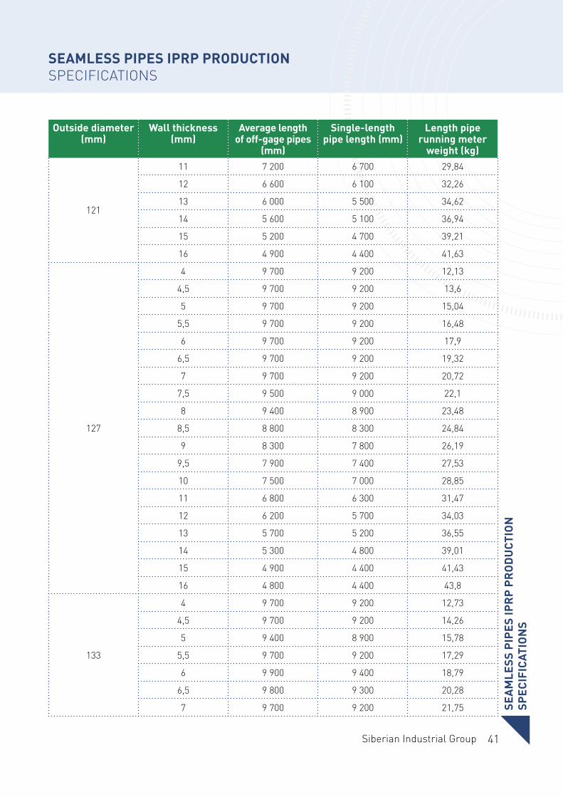
121
11 7 200 6 700 29,84
12 6 600 6 100 32,26
13 6 000 5 500 34,62
14 5 600 5 100 36,94
15 5 200 4 700 39,21
16 4 900 4 400 41,63
127
4 9 700 9 200 12,13
4,5 9 700 9 200 13,6
5 9 700 9 200 15,04
5,5 9 700 9 200 16,48
6 9 700 9 200 17,9
6,5 9 700 9 200 19,32
7 9 700 9 200 20,72
7,5 9 500 9 000 22,1
8 9 400 8 900 23,48
8,5 8 800 8 300 24,84
9 8 300 7 800 26,19
9,5 7 900 7 400 27,53
10 7 500 7 000 28,85
11 6 800 6 300 31,47
12 6 200 5 700 34,03
13 5 700 5 200 36,55
14 5 300 4 800 39,01
15 4 900 4 400 41,43
16 4 800 4 400 43,8
133
4 9 700 9 200 12,73
4,5 9 700 9 200 14,26
5 9 400 8 900 15,78
5,5 9 700 9 200 17,29
6 9 900 9 400 18,79
6,5 9 800 9 300 20,28
7 9 700 9 200 21,75
SEAMLESS PIPES IPRP PRODUCTIONSPECIFICATIONS
SEA
MLE
SS P
IPES
IPR
P PR
OD
UCT
ION
SPEC
IFIC
ATIO
NS
42
Outside diameter (mm)
Wall thickness (mm)
Average length of off-gage pipes
(mm)
Single-length pipe length (mm)
Length pipe running meter
weight (kg)
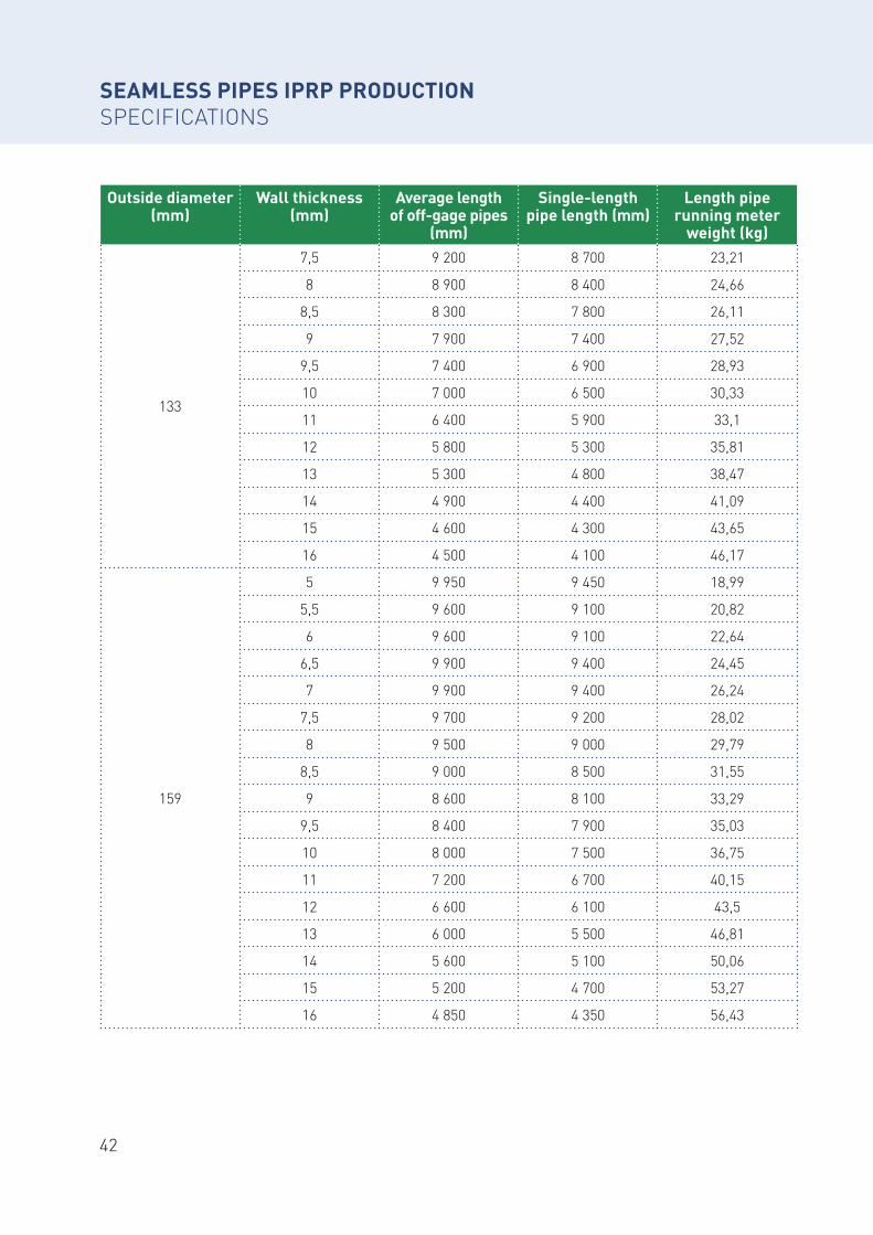
133
7,5 9 200 8 700 23,21
8 8 900 8 400 24,66
8,5 8 300 7 800 26,11
9 7 900 7 400 27,52
9,5 7 400 6 900 28,93
10 7 000 6 500 30,33
11 6 400 5 900 33,1
12 5 800 5 300 35,81
13 5 300 4 800 38,47
14 4 900 4 400 41,09
15 4 600 4 300 43,65
16 4 500 4 100 46,17
159
5 9 950 9 450 18,99
5,5 9 600 9 100 20,82
6 9 600 9 100 22,64
6,5 9 900 9 400 24,45
7 9 900 9 400 26,24
7,5 9 700 9 200 28,02
8 9 500 9 000 29,79
8,5 9 000 8 500 31,55
9 8 600 8 100 33,29
9,5 8 400 7 900 35,03
10 8 000 7 500 36,75
11 7 200 6 700 40,15
12 6 600 6 100 43,5
13 6 000 5 500 46,81
14 5 600 5 100 50,06
15 5 200 4 700 53,27
16 4 850 4 350 56,43
SEAMLESS PIPES IPRP PRODUCTIONSPECIFICATIONS
43Siberian Industrial Group
Outside diameter (mm)
Wall thickness (mm)
Average length of off-gage pipes
(mm)
Single-length pipe length (mm)
Length pipe running meter
weight (kg)
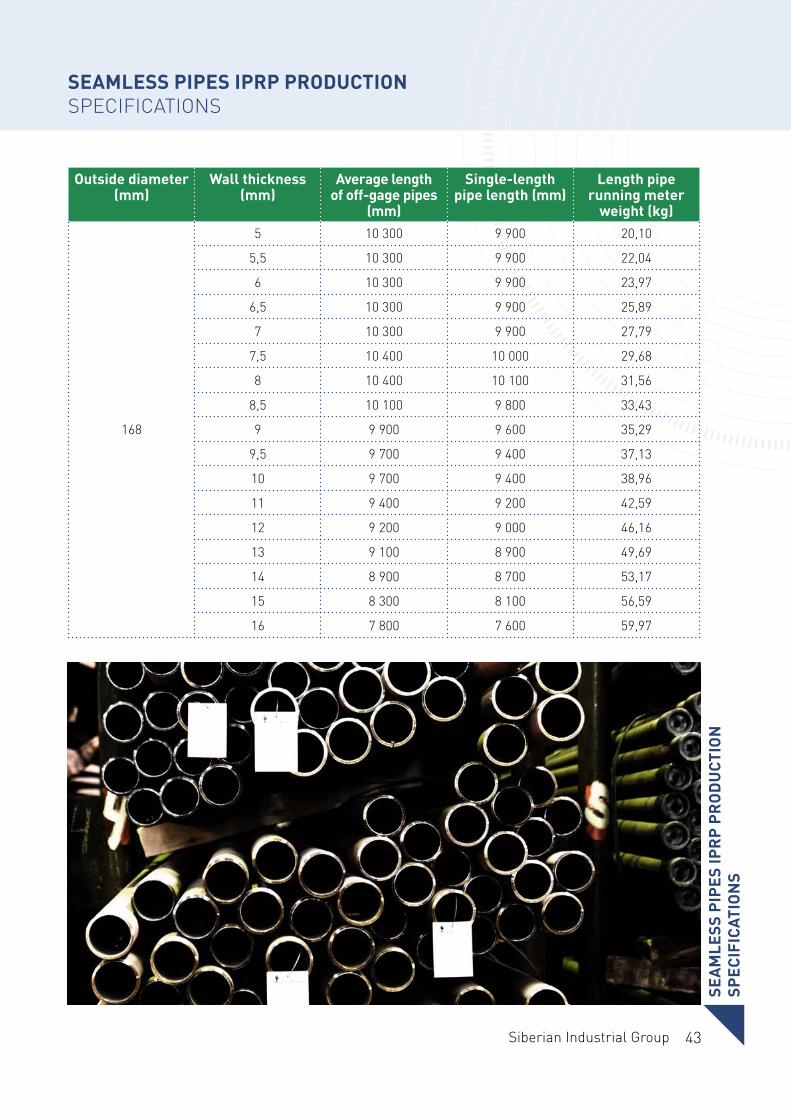
168
5 10 300 9 900 20,10
5,5 10 300 9 900 22,04
6 10 300 9 900 23,97
6,5 10 300 9 900 25,89
7 10 300 9 900 27,79
7,5 10 400 10 000 29,68
8 10 400 10 100 31,56
8,5 10 100 9 800 33,43
9 9 900 9 600 35,29
9,5 9 700 9 400 37,13
10 9 700 9 400 38,96
11 9 400 9 200 42,59
12 9 200 9 000 46,16
13 9 100 8 900 49,69
14 8 900 8 700 53,17
15 8 300 8 100 56,59
16 7 800 7 600 59,97
SEAMLESS PIPES IPRP PRODUCTIONSPECIFICATIONS
SEA
MLE
SS P
IPES
IPR
P PR
OD
UCT
ION
SPEC
IFIC
ATIO
NS
44
TU 14-3P-1128-2007 Cold-resistant seamless steel pipes for gas pipelines gas-lift systems for oil production and gas fields.
SEAMLESS CONVENTIONAL PIPES AND BOILER TUBES
Outside diameter (mm) Wall thickness (mm) Steel Grade
From 57 to 168 From 4 to 16 10, 20, 092G2C, 10G2
Outside diameter (mm) Wall thickness (mm) Steel Grade
From 57 to 168 From 4 to 1610, 20, 35, 45, St3sp, 092G2C,
10G2
Hot-deformed conventional pipesPIPES OBJECTIVE
Pipes are used in the construction, engineering, petrochemical industries, as well as in the con-struction of pipelines.
Thermal power sector pipes (Boiler tubes) PIPES OBJECTIVE
Boiler tubes are designed for steam boilers and pipelines.
Outside diameter (mm) Wall thickness (mm) Steel Grade
From 57 to 168 From 4 to 16 10, 20
TU 14-3-190-2004 Seamless steel pipes for boiler installations and pipelines.
GOST 8731-74, GOST 8732-78, GOST 32528-2013 Seamless hot-deformed steel pipes
45Siberian Industrial Group
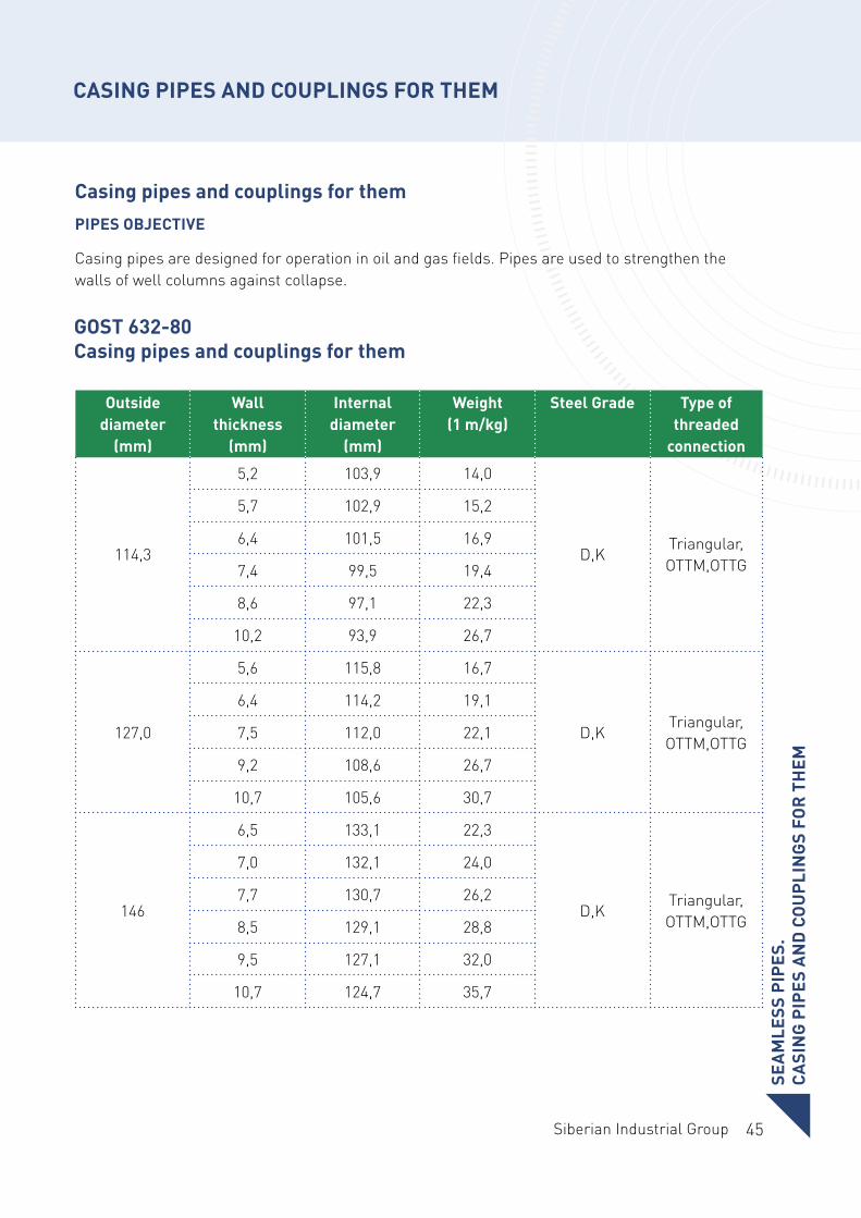
Casing pipes and couplings for themPIPES OBJECTIVE
Casing pipes are designed for operation in oil and gas fields. Pipes are used to strengthen the walls of well columns against collapse.
CASING PIPES AND COUPLINGS FOR THEM
Outside diameter
(mm)
Wall thickness
(mm)
Internal diameter
(mm)
Weight (1 m/kg)
Steel Grade Type of threaded
connection
114,3
5,2 103,9 14,0
D,K Triangular, OTTM,OTTG
5,7 102,9 15,2
6,4 101,5 16,9
7,4 99,5 19,4
8,6 97,1 22,3
10,2 93,9 26,7
127,0
5,6 115,8 16,7
D,K Triangular, OTTM,OTTG
6,4 114,2 19,1
7,5 112,0 22,1
9,2 108,6 26,7
10,7 105,6 30,7
146
6,5 133,1 22,3
D,K Triangular, OTTM,OTTG
7,0 132,1 24,0
7,7 130,7 26,2
8,5 129,1 28,8
9,5 127,1 32,0
10,7 124,7 35,7
SEA
MLE
SS P
IPES
.CA
SIN
G P
IPES
AN
D C
OU
PLIN
GS
FOR
TH
EM
GOST 632-80 Casing pipes and couplings for them
46
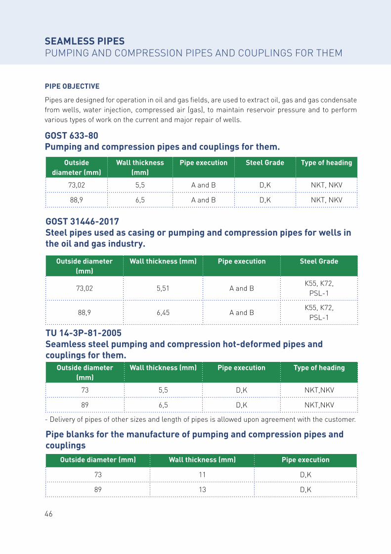
GOST 31446-2017 Steel pipes used as casing or pumping and compression pipes for wells in the oil and gas industry.
Pipe blanks for the manufacture of pumping and compression pipes and couplings
TU 14-3P-81-2005 Seamless steel pumping and compression hot-deformed pipes and couplings for them.
PIPE OBJECTIVE
Pipes are designed for operation in oil and gas fields, are used to extract oil, gas and gas condensate from wells, water injection, compressed air (gas), to maintain reservoir pressure and to perform various types of work on the current and major repair of wells.
GOST 633-80 Pumping and compression pipes and couplings for them.
- Delivery of pipes of other sizes and length of pipes is allowed upon agreement with the customer.
SEAMLESS PIPESPUMPING AND COMPRESSION PIPES AND COUPLINGS FOR THEM
Outside diameter (mm)
Wall thickness (mm)
Pipe execution Steel Grade Type of heading
73,02 5,5 A and B D,K NKT, NKV
88,9 6,5 A and B D,K NKT, NKV
Outside diameter (mm)
Wall thickness (mm) Pipe execution Steel Grade
73,02 5,51 A and BК55, К72,
PSL-1
88,9 6,45 A and BК55, К72,
PSL-1
Outside diameter (mm) Wall thickness (mm) Pipe execution
73 11 D,K
89 13 D,K
Outside diameter (mm)
Wall thickness (mm) Pipe execution Type of heading
73 5,5 D,K NKT,NKV
89 6,5 D,K NKT,NKV
47Siberian Industrial Group
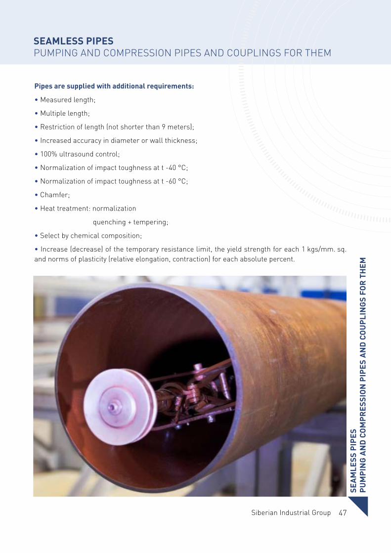
Pipes are supplied with additional requirements:
• Measured length;
• Multiple length;
• Restriction of length (not shorter than 9 meters);
• Increased accuracy in diameter or wall thickness;
• 100% ultrasound control;
• Normalization of impact toughness at t -40 °С;
• Normalization of impact toughness at t -60 °С;
• Chamfer;
• Heat treatment: normalization
quenching + tempering;
• Select by chemical composition;
• Increase (decrease) of the temporary resistance limit, the yield strength for each 1 kgs/mm. sq. and norms of plasticity (relative elongation, contraction) for each absolute percent.
SEAMLESS PIPESPUMPING AND COMPRESSION PIPES AND COUPLINGS FOR THEM
SEA
MLE
SS P
IPES
PUM
PIN
G A
ND
CO
MPR
ESSI
ON
PIP
ES A
ND
CO
UPL
ING
S FO
R T
HEM
48
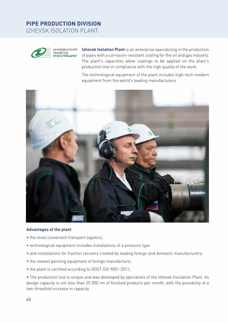
Izhevsk Isolation Plant is an enterprise specializing in the production of pipes with a corrosion-resistant coating for the oil and gas industry. The plant’s capacities allow coatings to be applied on the plant’s production line in compliance with the high quality of the work.
The technological equipment of the plant includes high-tech modern equipment from the world’s leading manufacturers.
Advantages of the plant
• the most convenient transport logistics;
• technological equipment includes installations of a pressure type
• and installations for fraction recovery created by leading foreign and domestic manufacturers;
• the newest painting equipment of foreign manufacture;
• the plant is certified according to GOST ISO 9001-2011;
• The production line is unique and was developed by specialists of the Izhevsk Insulation Plant. Its design capacity is not less than 25 000 rm of finished products per month, with the possibility of a two-threefold increase in capacity.
PIPE PRODUCTION DIVISIONIZHEVSK ISOLATION PLANT

49Siberian Industrial Group
50
CERTIFICATES AND DOCUMENTATIONIZHEVSK ISOLATION PLANT
51Siberian Industrial Group
CER
TIFI
CATE
S A
ND
DO
CUM
ENTA
TIO
NIZ
HEV
SK IS
OLA
TIO
N P
LAN
T
CERTIFICATES AND DOCUMENTATIONIZHEVSK ISOLATION PLANT
52
PIPES WITH EXTERNAL CORROSION-RESISTANT COATING
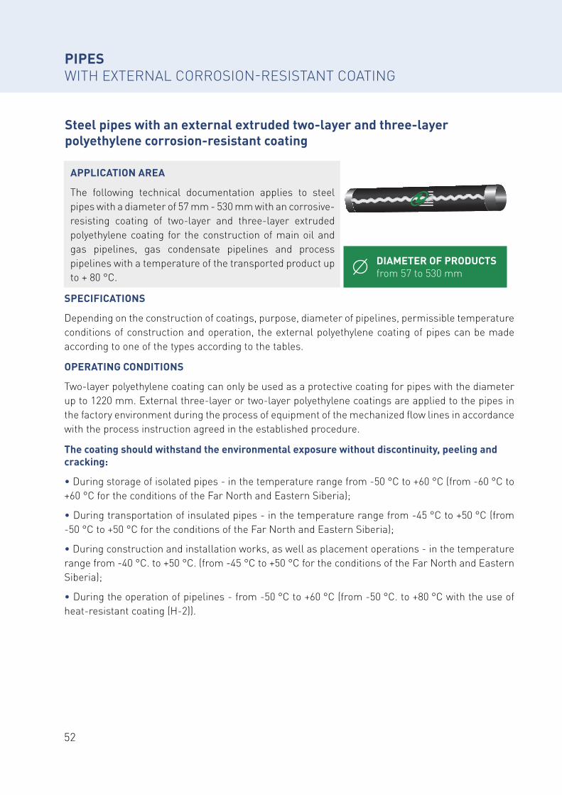
Steel pipes with an external extruded two-layer and three-layer polyethylene corrosion-resistant coating
SPECIFICATIONS
Depending on the construction of coatings, purpose, diameter of pipelines, permissible temperature conditions of construction and operation, the external polyethylene coating of pipes can be made according to one of the types according to the tables.
OPERATING CONDITIONS
Two-layer polyethylene coating can only be used as a protective coating for pipes with the diameter up to 1220 mm. External three-layer or two-layer polyethylene coatings are applied to the pipes in the factory environment during the process of equipment of the mechanized flow lines in accordance with the process instruction agreed in the established procedure.
The coating should withstand the environmental exposure without discontinuity, peeling and cracking:
• During storage of isolated pipes - in the temperature range from -50 °C to +60 °C (from -60 °C to +60 °C for the conditions of the Far North and Eastern Siberia);
• During transportation of insulated pipes - in the temperature range from -45 °C to +50 °C (from -50 °C to +50 °C for the conditions of the Far North and Eastern Siberia);
• During construction and installation works, as well as placement operations - in the temperature range from -40 °C. to +50 °C. (from -45 °C to +50 °C for the conditions of the Far North and Eastern Siberia);
• During the operation of pipelines - from -50 °C to +60 °C (from -50 °C. to +80 °C with the use of heat-resistant coating (H-2)).
APPLICATION AREA
The following technical documentation applies to steel pipes with a diameter of 57 mm - 530 mm with an corrosive-resisting coating of two-layer and three-layer extruded polyethylene coating for the construction of main oil and gas pipelines, gas condensate pipelines and process pipelines with a temperature of the transported product up to + 80 °C.
DIAMETER OF PRODUCTS from 57 to 530 mm
53Siberian Industrial Group
PIPES WITH EXTERNAL CORROSION-RESISTANT COATING
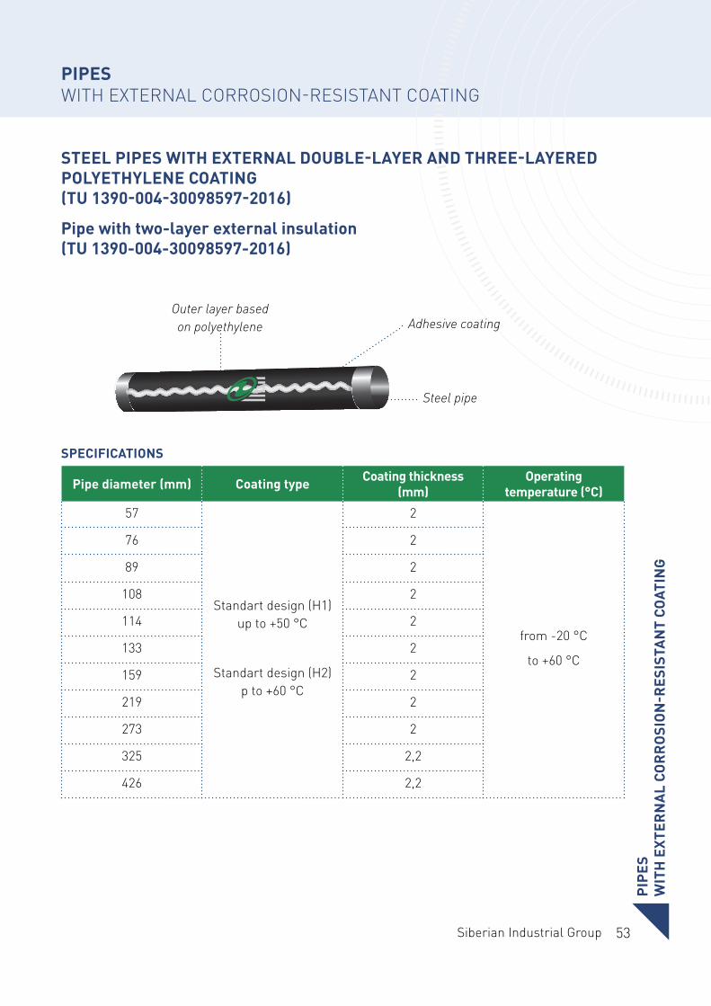
STEEL PIPES WITH EXTERNAL DOUBLE-LAYER AND THREE-LAYERED POLYETHYLENE COATING (TU 1390-004-30098597-2016)
Pipe with two-layer external insulation (TU 1390-004-30098597-2016)
Pipe diameter (mm) Coating type Coating thickness (mm)
Operating temperature (°C)
57
Standart design (Н1) up to +50 °С
Standart design (Н2) p to +60 °С
2
from -20 °С
to +60 °С
76 2
89 2
108 2
114 2
133 2
159 2
219 2
273 2
325 2,2
426 2,2
Outer layer based on polyethylene Adhesive coating
Steel pipe
PIPE
S W
ITH
EXT
ERN
AL
COR
RO
SIO
N-R
ESIS
TAN
T CO
ATIN
G
SPECIFICATIONS
54
SPECIFICATIONS
PIPES WITH EXTERNAL CORROSION-RESISTANT COATING
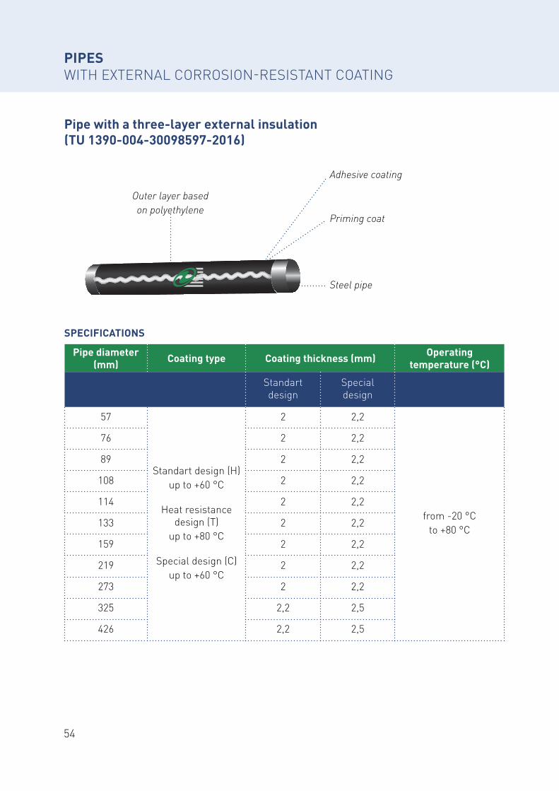
Pipe with a three-layer external insulation (TU 1390-004-30098597-2016)
Pipe diameter (mm) Coating type Coating thickness (mm) Operating
temperature (°C)
Standart design
Special design
57
Standart design (Н) up to +60 °С
Heat resistance design (Т)
up to +80 °С
Special design (С) up to +60 °С
2 2,2
from -20 °Сto +80 °С
76 2 2,2
89 2 2,2
108 2 2,2
114 2 2,2
133 2 2,2
159 2 2,2
219 2 2,2
273 2 2,2
325 2,2 2,5
426 2,2 2,5
Outer layer based on polyethylene
Priming coat
Adhesive coating
Steel pipe
55Siberian Industrial Group
56
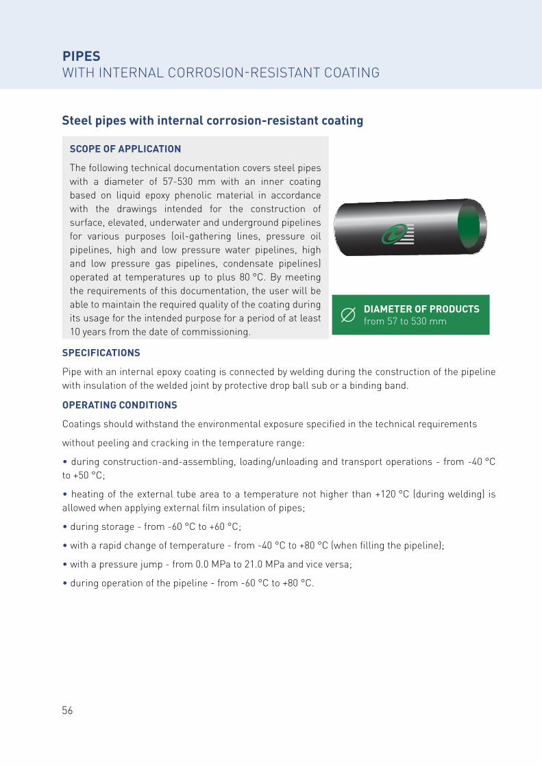
Steel pipes with internal corrosion-resistant coating
PIPES WITH INTERNAL CORROSION-RESISTANT COATING
DIAMETER OF PRODUCTS from 57 to 530 mm
SCOPE OF APPLICATION
The following technical documentation covers steel pipes with a diameter of 57-530 mm with an inner coating based on liquid epoxy phenolic material in accordance with the drawings intended for the construction of surface, elevated, underwater and underground pipelines for various purposes (oil-gathering lines, pressure oil pipelines, high and low pressure water pipelines, high and low pressure gas pipelines, condensate pipelines) operated at temperatures up to plus 80 °C. By meeting the requirements of this documentation, the user will be able to maintain the required quality of the coating during its usage for the intended purpose for a period of at least 10 years from the date of commissioning.
SPECIFICATIONS
Pipe with an internal epoxy coating is connected by welding during the construction of the pipeline with insulation of the welded joint by protective drop ball sub or a binding band.
OPERATING CONDITIONS
Coatings should withstand the environmental exposure specified in the technical requirements
without peeling and cracking in the temperature range:
• during construction-and-assembling, loading/unloading and transport operations - from -40 °C to +50 °C;
• heating of the external tube area to a temperature not higher than +120 °C (during welding) is allowed when applying external film insulation of pipes;
• during storage - from -60 °C to +60 °C;
• with a rapid change of temperature - from -40 °C to +80 °C (when filling the pipeline);
• with a pressure jump - from 0.0 MPa to 21.0 MPa and vice versa;
• during operation of the pipeline - from -60 °C to +80 °C.
57Siberian Industrial Group
PIPESWITH INTERNAL CORROSION-RESISTANT COATING
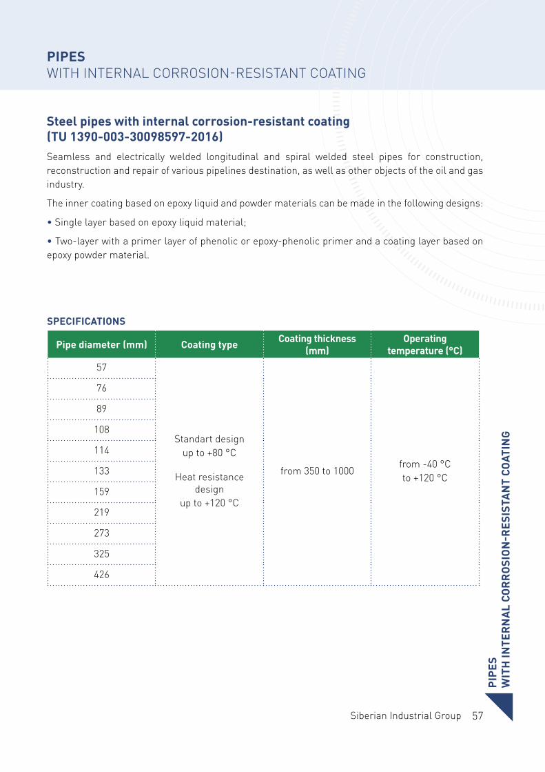
Steel pipes with internal corrosion-resistant coating (TU 1390-003-30098597-2016)Seamless and electrically welded longitudinal and spiral welded steel pipes for construction, reconstruction and repair of various pipelines destination, as well as other objects of the oil and gas industry.
The inner coating based on epoxy liquid and powder materials can be made in the following designs:
• Single layer based on epoxy liquid material;
• Two-layer with a primer layer of phenolic or epoxy-phenolic primer and a coating layer based on epoxy powder material.
Pipe diameter (mm) Coating type Coating thickness (mm)
Operating temperature (°C)
57
Standart design up to +80 °С
Heat resistance design
up to +120 °С
from 350 to 1000from -40 °Сto +120 °С
76
89
108
114
133
159
219
273
325
426
PIPE
SW
ITH
INTE
RN
AL
COR
RO
SIO
N-R
ESIS
TAN
T CO
ATIN
G
SPECIFICATIONS
58
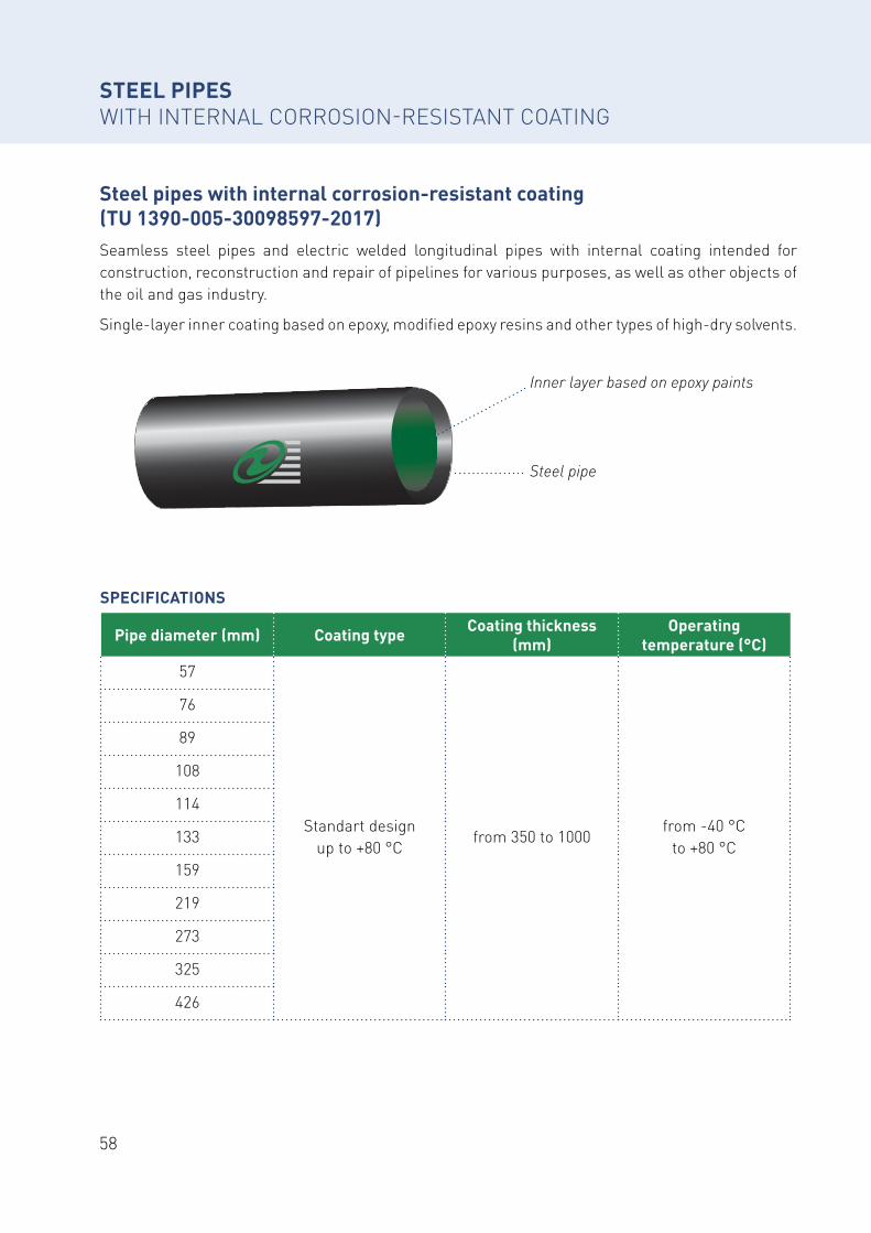
STEEL PIPESWITH INTERNAL CORROSION-RESISTANT COATING
Steel pipes with internal corrosion-resistant coating (TU 1390-005-30098597-2017)Seamless steel pipes and electric welded longitudinal pipes with internal coating intended for construction, reconstruction and repair of pipelines for various purposes, as well as other objects of the oil and gas industry.
Single-layer inner coating based on epoxy, modified epoxy resins and other types of high-dry solvents.
Pipe diameter (mm) Coating type Coating thickness (mm)
Operating temperature (°C)
57
Standart design up to +80 °С
from 350 to 1000from -40 °С
to +80 °С
76
89
108
114
133
159
219
273
325
426
Inner layer based on epoxy paints
Steel pipe
SPECIFICATIONS
59Siberian Industrial Group
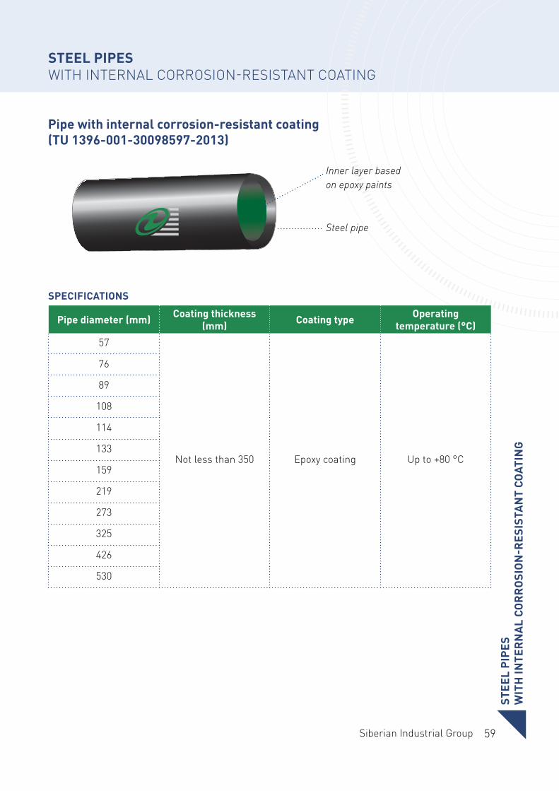
Pipe with internal corrosion-resistant coating (TU 1396-001-30098597-2013)
Inner layer based on epoxy paints
Steel pipe
STEEL PIPESWITH INTERNAL CORROSION-RESISTANT COATING
Pipe diameter (mm) Coating thickness (mm) Coating type Operating
temperature (°C)
57
Not less than 350 Epoxy coating Up to +80 °C
76
89
108
114
133
159
219
273
325
426
530
STEE
L PI
PES
WIT
H IN
TER
NA
L CO
RR
OSI
ON
-RES
ISTA
NT
COAT
ING
SPECIFICATIONS
60
PIPE PRODUCTION DIVISIONTVEL-TOBOLSK PLANT
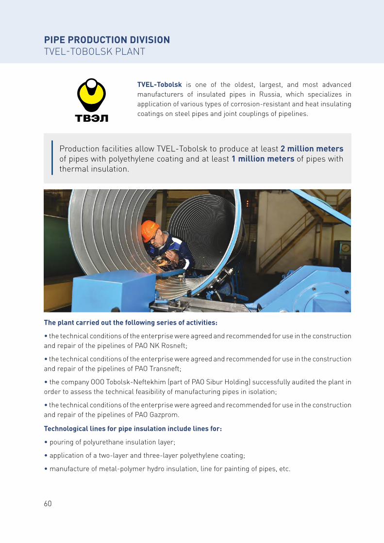
TVEL-Tobolsk is one of the oldest, largest, and most advanced manufacturers of insulated pipes in Russia, which specializes in application of various types of corrosion-resistant and heat insulating coatings on steel pipes and joint couplings of pipelines.
Production facilities allow TVEL-Tobolsk to produce at least 2 million meters of pipes with polyethylene coating and at least 1 million meters of pipes with thermal insulation.
The plant carried out the following series of activities:
• the technical conditions of the enterprise were agreed and recommended for use in the construction and repair of the pipelines of PAO NK Rosneft;
• the technical conditions of the enterprise were agreed and recommended for use in the construction and repair of the pipelines of PAO Transneft;
• the company OOO Tobolsk-Neftekhim (part of PAO Sibur Holding) successfully audited the plant in order to assess the technical feasibility of manufacturing pipes in isolation;
• the technical conditions of the enterprise were agreed and recommended for use in the construction and repair of the pipelines of PAO Gazprom.
Technological lines for pipe insulation include lines for:
• pouring of polyurethane insulation layer;
• application of a two-layer and three-layer polyethylene coating;
• manufacture of metal-polymer hydro insulation, line for painting of pipes, etc.

61Siberian Industrial Group
62
CERTIFICATES AND DOCUMENTATION OF TVEL-TOBOLSK
63Siberian Industrial Group
CER
TIFI
CATE
S A
ND
DO
CUM
ENTA
TIO
N
OF
TVEL
-TO
BO
LSK
CERTIFICATES AND DOCUMENTATION OF TVEL-TOBOLSK
64
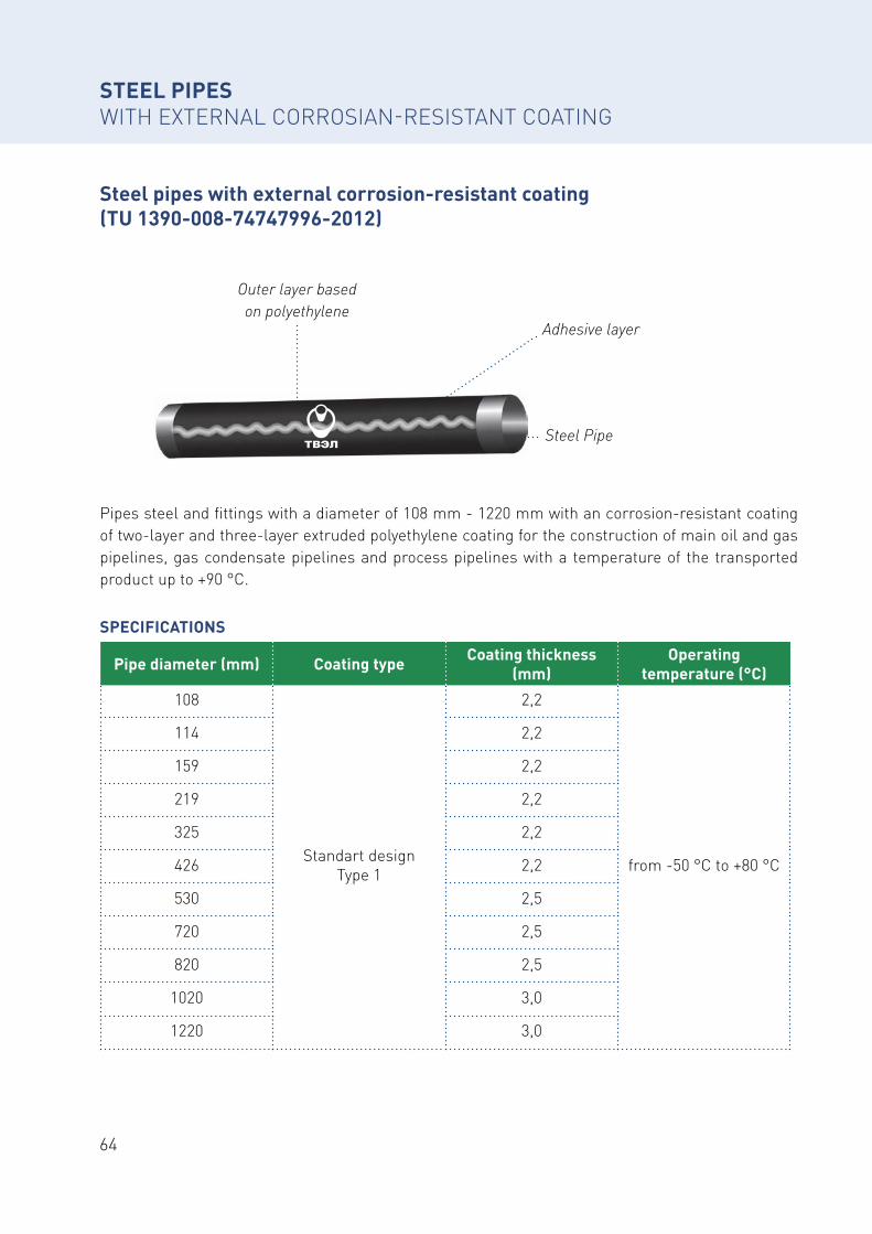
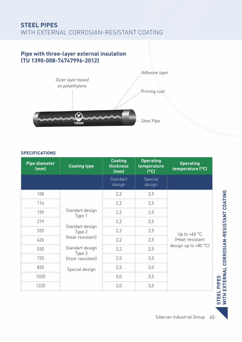
Pipes steel and fittings with a diameter of 108 mm - 1220 mm with an сorrosion-resistant coating of two-layer and three-layer extruded polyethylene coating for the construction of main oil and gas pipelines, gas condensate pipelines and process pipelines with a temperature of the transported product up to +90 °С.
SPECIFICATIONS
STEEL PIPES WITH EXTERNAL CORROSIAN-RESISTANT COATING
Steel pipes with external corrosion-resistant coating (TU 1390-008-74747996-2012)
Pipe diameter (mm) Coating type Coating thickness (mm)
Operating temperature (°C)
108
Standart design Type 1
2,2
from -50 °С to +80 °С
114 2,2
159 2,2
219 2,2
325 2,2
426 2,2
530 2,5
720 2,5
820 2,5
1020 3,0
1220 3,0
Outer layer based on polyethylene
Adhesive layer
Steel Pipe
65Siberian Industrial Group
STEE
L PI
PES
WIT
H E
XTER
NA
L CO
RR
OSI
AN
-RES
ISTA
NT
COAT
ING
SPECIFICATIONS
STEEL PIPES WITH EXTERNAL CORROSIAN-RESISTANT COATING
Pipe with three-layer external insulation (TU 1390-008-74747996-2012)
Pipe diameter (mm) Coating type
Coating thickness
(mm)
Operating temperature
(°C)
Operating temperature (°C)
Standart design
Special design
108
Standart design Type 1
Standart design Type 2
(heat-resistant)
Standart design Type 3
(frost-resistant)
Special design
2,2 2,5
Up to +60 °C(Heat-resistant
design up to +80 °C)
114 2,2 2,5
159 2,2 2,5
219 2,2 2,5
325 2,2 2,5
426 2,2 2,5
530 2,2 2,5
720 2,5 3,0
820 2,5 3,0
1020 3,0 3,5
1220 3,0 3,5
Outer layer based on polyethylene
Adhesive layer
Steel Pipe
Priming coat
66
Outer layer based on polyethylene
Adhesive layer
Steel Pipe
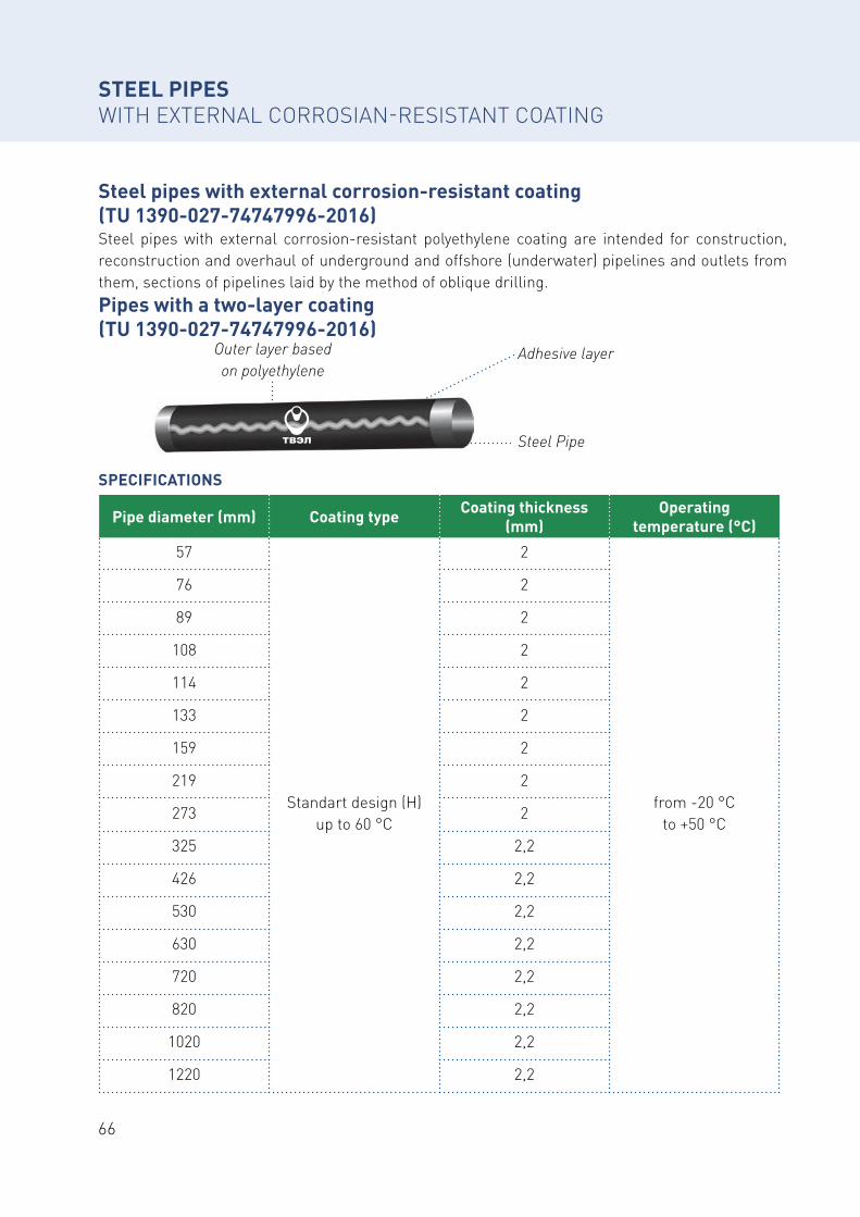
STEEL PIPES WITH EXTERNAL CORROSIAN-RESISTANT COATING
Steel pipes with external corrosion-resistant coating (TU 1390-027-74747996-2016)Steel pipes with external corrosion-resistant polyethylene coating are intended for construction, reconstruction and overhaul of underground and offshore (underwater) pipelines and outlets from them, sections of pipelines laid by the method of oblique drilling.Pipes with a two-layer coating (TU 1390-027-74747996-2016)
Pipe diameter (mm) Coating type Coating thickness (mm)
Operating temperature (°C)
57
Standart design (H) up to 60 °C
2
from -20 °Cto +50 °С
76 2
89 2
108 2
114 2
133 2
159 2
219 2
273 2
325 2,2
426 2,2
530 2,2
630 2,2
720 2,2
820 2,2
1020 2,2
1220 2,2
SPECIFICATIONS
67Siberian Industrial Group
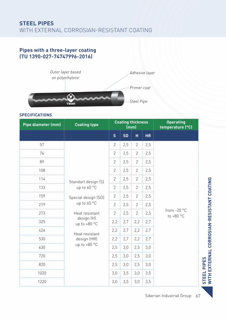
STEEL PIPES WITH EXTERNAL CORROSIAN-RESISTANT COATING
Pipes with a three-layer coating (TU 1390-027-74747996-2016)
Pipe diameter (mm) Coating type Coating thickness (mm)
Operating temperature (°C)
S SD H HR
57
Standart design (S) up to 60 °C
Special design (SD) up to 60 °C
Heat resistant design (H)
up to +80 °С
Heat resistant design (HR) up to +80 °С
2 2,5 2 2,5
from -20 °Сto +80 °С
76 2 2,5 2 2,5
89 2 2,5 2 2,5
108 2 2,5 2 2,5
114 2 2,5 2 2,5
133 2 2,5 2 2,5
159 2 2,5 2 2,5
219 2 2,5 2 2,5
273 2 2,5 2 2,5
325 2,2 2,7 2,2 2,7
426 2,2 2,7 2,2 2,7
530 2,2 2,7 2,2 2,7
630 2,5 3,0 2,5 3,0
720 2,5 3,0 2,5 3,0
820 2,5 3,0 2,5 3,0
1020 3,0 3,5 3,0 3,5
1220 3,0 3,5 3,0 3,5
Outer layer based on polyethylene
Primer coat
Adhesive layer
Steel Pipe
STEE
L PI
PES
WIT
H E
XTER
NA
L CO
RR
OSI
AN
-RES
ISTA
NT
COAT
ING
SPECIFICATIONS
68
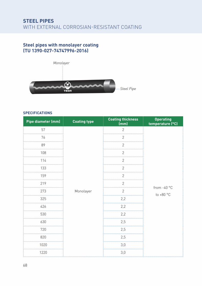
STEEL PIPES WITH EXTERNAL CORROSIAN-RESISTANT COATING
Steel pipes with monolayer coating (TU 1390-027-74747996-2016)
Pipe diameter (mm) Coating type Coating thickness (mm)
Operating temperature (°C)
57
Monolayer
2
from -40 °С
to +80 °С
76 2
89 2
108 2
114 2
133 2
159 2
219 2
273 2
325 2,2
426 2,2
530 2,2
630 2,5
720 2,5
820 2,5
1020 3,0
1220 3,0
Monolayer
Steel Pipe
SPECIFICATIONS
69Siberian Industrial Group
STEEL PIPES WITH EXTERNAL CORROSIAN-RESISTANT COATING
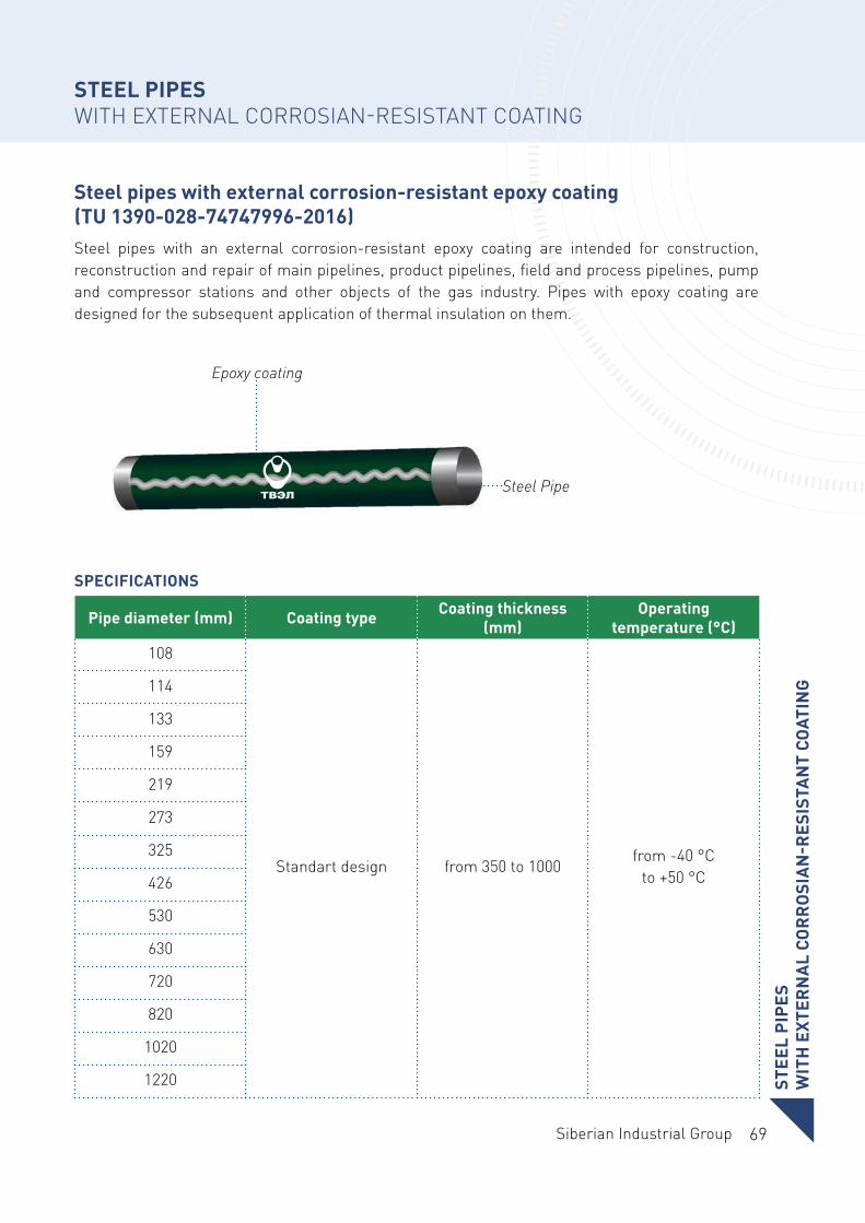
Steel pipes with external corrosion-resistant epoxy coating (TU 1390-028-74747996-2016)Steel pipes with an external corrosion-resistant epoxy coating are intended for construction, reconstruction and repair of main pipelines, product pipelines, field and process pipelines, pump and compressor stations and other objects of the gas industry. Pipes with epoxy coating are designed for the subsequent application of thermal insulation on them.
Pipe diameter (mm) Coating type Coating thickness (mm)
Operating temperature (°C)
108
Standart design from 350 to 1000from -40 °С
to +50 °С
114
133
159
219
273
325
426
530
630
720
820
1020
1220
Epoxy coating
Steel Pipe
STEE
L PI
PES
WIT
H E
XTER
NA
L CO
RR
OSI
AN
-RES
ISTA
NT
COAT
ING
SPECIFICATIONS
70
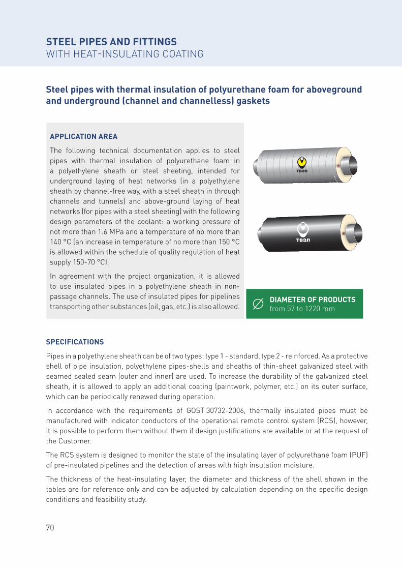
Steel pipes with thermal insulation of polyurethane foam for aboveground and underground (channel and channelless) gaskets
STEEL PIPES AND FITTINGS WITH HEAT-INSULATING COATING
DIAMETER OF PRODUCTS from 57 to 1220 mm
APPLICATION AREA
The following technical documentation applies to steel pipes with thermal insulation of polyurethane foam in a polyethylene sheath or steel sheeting, intended for underground laying of heat networks (in a polyethylene sheath by channel-free way, with a steel sheath in through channels and tunnels) and above-ground laying of heat networks (for pipes with a steel sheeting) with the following design parameters of the coolant: a working pressure of not more than 1.6 MPa and a temperature of no more than 140 °C (an increase in temperature of no more than 150 °C is allowed within the schedule of quality regulation of heat supply 150-70 °C).
In agreement with the project organization, it is allowed to use insulated pipes in a polyethylene sheath in non-passage channels. The use of insulated pipes for pipelines transporting other substances (oil, gas, etc.) is also allowed.
SPECIFICATIONS
Pipes in a polyethylene sheath can be of two types: type 1 - standard, type 2 - reinforced. As a protective shell of pipe insulation, polyethylene pipes-shells and sheaths of thin-sheet galvanized steel with seamed sealed seam (outer and inner) are used. To increase the durability of the galvanized steel sheath, it is allowed to apply an additional coating (paintwork, polymer, etc.) on its outer surface, which can be periodically renewed during operation.
In accordance with the requirements of GOST 30732-2006, thermally insulated pipes must be manufactured with indicator conductors of the operational remote control system (RCS), however, it is possible to perform them without them if design justifications are available or at the request of the Customer.
The RCS system is designed to monitor the state of the insulating layer of polyurethane foam (PUF) of pre-insulated pipelines and the detection of areas with high insulation moisture.
The thickness of the heat-insulating layer, the diameter and thickness of the shell shown in the tables are for reference only and can be adjusted by calculation depending on the specific design conditions and feasibility study.
71Siberian Industrial Group
OPERATING CONDITIONS
The permissible operating temperature of the thermal insulation coating is determined by the brand of polyurethane foam used and may be in the range of 80-130 °C.
Loading and unloading work is carried out in the temperature range specified for construction and installation works, but not below:
• minus 18 °С - for pipes with a polyethylene sheath;
• minus 50 °С - for pipes with a steel sheath.
In coordination with the customer, when using special grades of polyethylene shells and while ensuring the safety of insulated pipes, it is allowed to work at lower temperatures.
STEEL PIPES AND FITTINGS WITH HEAT-INSULATING COATING
STEE
L PI
PES
AN
D F
ITTI
NG
S W
ITH
HEA
T-IN
SULA
TIN
G C
OAT
ING
72
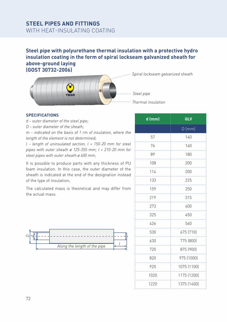
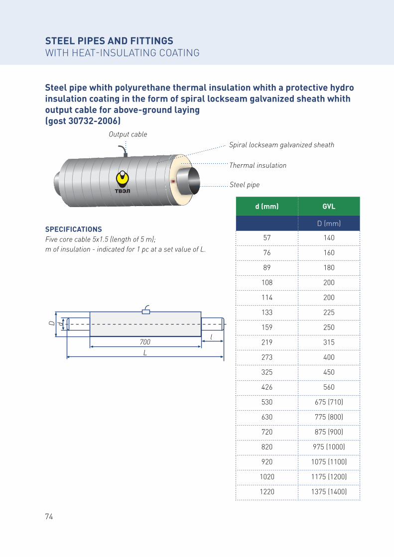
Steel pipe with polyurethane thermal insulation with a protective hydro insulation coating in the form of spiral lockseam galvanized sheath for above-ground laying (GOST 30732-2006)
STEEL PIPES AND FITTINGS WITH HEAT-INSULATING COATING
SPECIFICATIONSd – outer diameter of the steel pipe;D – outer diameter of the sheath;m – indicated on the basis of 1 rm of insulation, where the length of the element is not determined;l – length of uninsulated section, l = 150-20 mm for steel pipes with outer sheath ø 125-355 mm; l = 210-20 mm for steel pipes with outer sheath ø 400 mm;
It is possible to produce parts with any thickness of PU foam insulation. In this case, the outer diameter of the sheath is indicated at the end of the designation instead of the type of insulation;
The calculated mass is theoretical and may differ from the actual mass.
Spiral lockseam galvanized sheath
Thermal insulation
Steel pipe
d (mm) GLV
D (mm)
57 140
76 160
89 180
108 200
114 200
133 225
159 250
219 315
273 400
325 450
426 560
530 675 (710)
630 775 (800)
720 875 (900)
820 975 (1000)
920 1075 (1100)
1020 1175 (1200)
1220 1375 (1400)
Along the length of the pipe
D d
l
73Siberian Industrial Group
STEE
L PI
PES
AN
D F
ITTI
NG
S W
ITH
HEA
T-IN
SULA
TIN
G C
OAT
ING
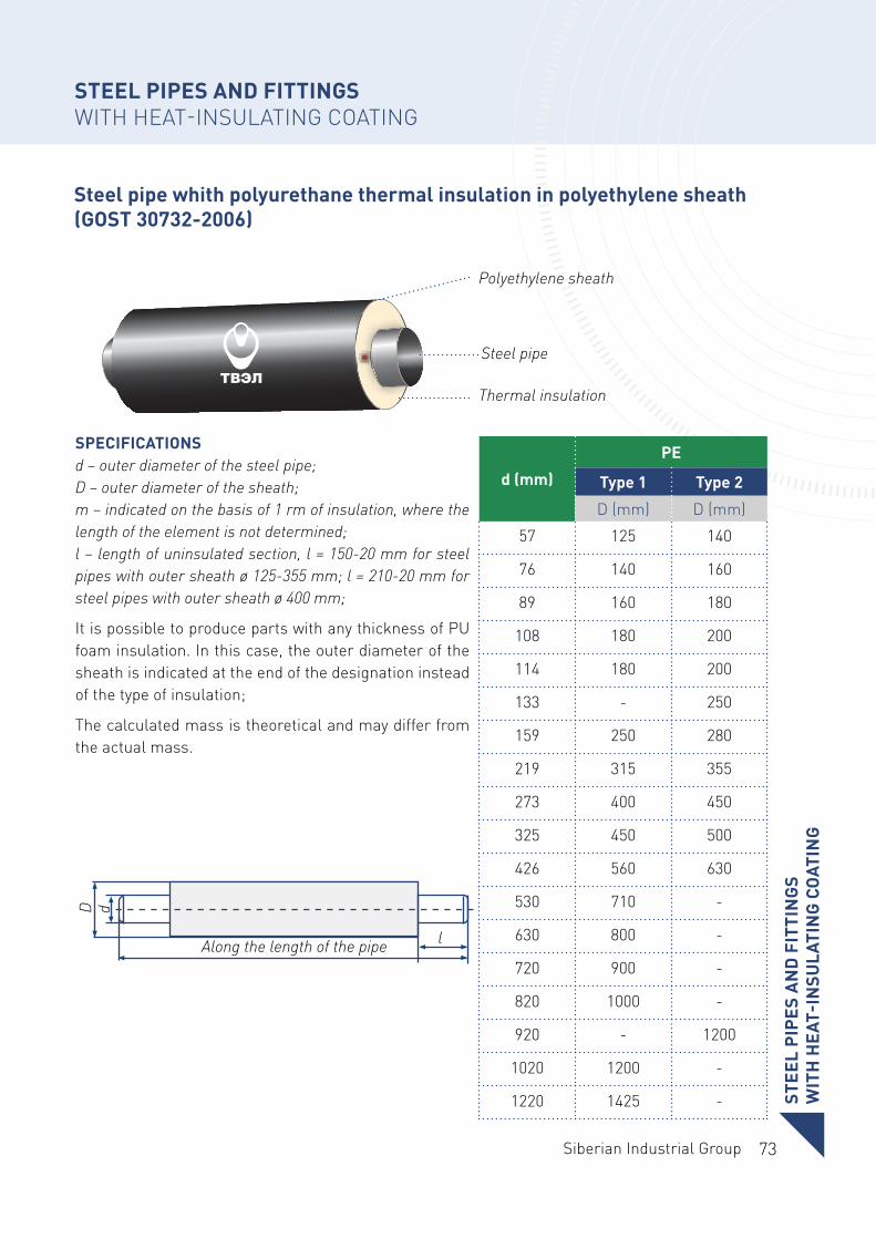
Steel pipe whith polyurethane thermal insulation in polyethylene sheath (GOST 30732-2006)
STEEL PIPES AND FITTINGS WITH HEAT-INSULATING COATING
SPECIFICATIONSd – outer diameter of the steel pipe;D – outer diameter of the sheath;m – indicated on the basis of 1 rm of insulation, where the length of the element is not determined;l – length of uninsulated section, l = 150-20 mm for steel pipes with outer sheath ø 125-355 mm; l = 210-20 mm for steel pipes with outer sheath ø 400 mm;
It is possible to produce parts with any thickness of PU foam insulation. In this case, the outer diameter of the sheath is indicated at the end of the designation instead of the type of insulation;
The calculated mass is theoretical and may differ from the actual mass.
Polyethylene sheath
Thermal insulation
Steel pipe
d (mm)
PE
Type 1 Type 2
D (mm) D (mm)
57 125 140
76 140 160
89 160 180
108 180 200
114 180 200
133 - 250
159 250 280
219 315 355
273 400 450
325 450 500
426 560 630
530 710 -
630 800 -
720 900 -
820 1000 -
920 - 1200
1020 1200 -
1220 1425 -
Along the length of the pipe
D d
l
74
Steel pipe whith polyurethane thermal insulation whith a protective hydro insulation coating in the form of spiral lockseam galvanized sheath whith output cable for above-ground laying (gost 30732-2006)
STEEL PIPES AND FITTINGS WITH HEAT-INSULATING COATING
SPECIFICATIONSFive core cable 5x1.5 (length of 5 m);m of insulation - indicated for 1 pc at a set value of L.
Spiral lockseam galvanized sheath
Thermal insulation
Output cable
Steel pipe
d (mm) GVL
D (mm)
57 140
76 160
89 180
108 200
114 200
133 225
159 250
219 315
273 400
325 450
426 560
530 675 (710)
630 775 (800)
720 875 (900)
820 975 (1000)
920 1075 (1100)
1020 1175 (1200)
1220 1375 (1400)
700L
D d
l
75Siberian Industrial Group
STEE
L PI
PES
AN
D F
ITTI
NG
S W
ITH
HEA
T-IN
SULA
TIN
G C
OAT
ING
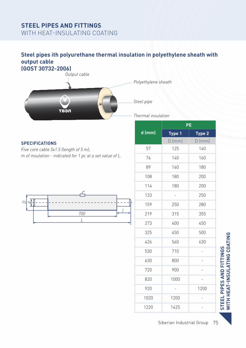
Steel pipes ith polyurethane thermal insulation in polyethylene sheath with output cable (GOST 30732-2006)
STEEL PIPES AND FITTINGS WITH HEAT-INSULATING COATING
SPECIFICATIONSFive core cable 5x1.5 (length of 5 m);m of insulation - indicated for 1 pc at a set value of L.
d (mm)
PE
Type 1 Type 2
D (mm) D (mm)
57 125 140
76 140 160
89 160 180
108 180 200
114 180 200
133 - 250
159 250 280
219 315 355
273 400 450
325 450 500
426 560 630
530 710 -
630 800 -
720 900 -
820 1000 -
920 - 1200
1020 1200 -
1220 1425 -
Polyethylene sheath
Thermal insulation
Output cable
Steel pipe
700L
D d
l
76
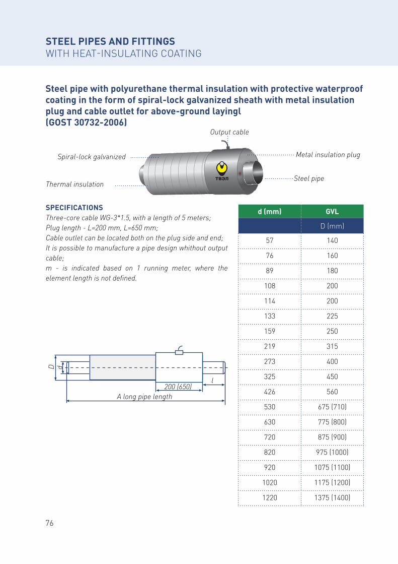
Steel pipe with polyurethane thermal insulation with protective waterproof coating in the form of spiral-lock galvanized sheath with metal insulation plug and cable outlet for above-ground layingl (GOST 30732-2006)
STEEL PIPES AND FITTINGSWITH HEAT-INSULATING COATING
SPECIFICATIONSThree-core cable WG-3*1.5, with a length of 5 meters;Plug length - L=200 mm, L=650 mm;Cable outlet can be located both on the plug side and end;It is possible to manufacture a pipe design whithout output cable;m - is indicated based on 1 running meter, where the element length is not defined.
Spiral-lock galvanized
Thermal insulation
Output cable
Steel pipe
Metal insulation plug
d (mm) GVL
D (mm)
57 140
76 160
89 180
108 200
114 200
133 225
159 250
219 315
273 400
325 450
426 560
530 675 (710)
630 775 (800)
720 875 (900)
820 975 (1000)
920 1075 (1100)
1020 1175 (1200)
1220 1375 (1400)
200 (650)A long pipe length
D d
l
77Siberian Industrial Group
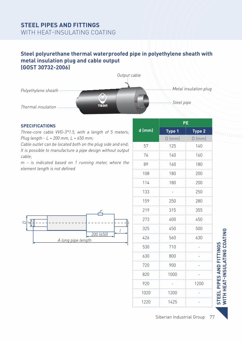
Steel polyurethane thermal waterproofed pipe in polyethylene sheath with metal insulation plug and cable output (GOST 30732-2006)
STEEL PIPES AND FITTINGSWITH HEAT-INSULATING COATING
SPECIFICATIONSThree-core cable VVG-3*1.5, with a length of 5 meters; Plug length - L = 200 mm, L = 650 mm;Cable outlet can be located both on the plug side and end;It is possible to manufacture a pipe design without output cable;m – is indicated based on 1 running meter, where the element length is not defined
Polyethylene sheath
Thermal insulation
Output cable
Steel pipe
Metal insulation plug
200 (650)A long pipe length
D d
l
d (mm)
PE
Type 1 Type 2
D (mm) D (mm)
57 125 140
76 140 160
89 160 180
108 180 200
114 180 200
133 - 250
159 250 280
219 315 355
273 400 450
325 450 500
426 560 630
530 710 -
630 800 -
720 900 -
820 1000 -
920 - 1200
1020 1200 -
1220 1425 - STEE
L PI
PES
AN
D F
ITTI
NG
SW
ITH
HEA
T-IN
SULA
TIN
G C
OAT
ING
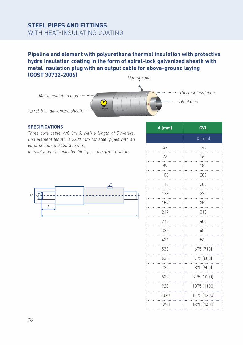
78
Pipeline end element with polyurethane thermal insulation with protective hydro insulation coating in the form of spiral-lock galvanized sheath with metal insulation plug with an output cable for above-ground laying (GOST 30732-2006)
STEEL PIPES AND FITTINGS WITH HEAT-INSULATING COATING
SPECIFICATIONSThree-core cable VVG-3*1.5, with a length of 5 meters; End element length is 2200 mm for steel pipes with an outer sheath of ø 125-355 mm;m insulation - is indicated for 1 pcs. at a given L value.
Metal insulation plug
Spiral-lock galvanized sheath
Output cable
Steel pipe
Thermal insulation
d (mm) GVL
D (mm)
57 140
76 160
89 180
108 200
114 200
133 225
159 250
219 315
273 400
325 450
426 560
530 675 (710)
630 775 (800)
720 875 (900)
820 975 (1000)
920 1075 (1100)
1020 1175 (1200)
1220 1375 (1400)
L
D d
l
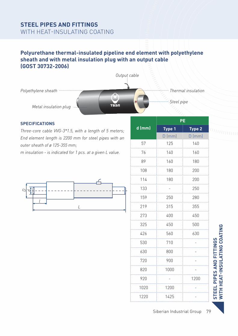
79Siberian Industrial Group
Polyurethane thermal-insulated pipeline end element with polyethylene sheath and with metal insulation plug with an output cable (GOST 30732-2006)
STEEL PIPES AND FITTINGS WITH HEAT-INSULATING COATING
SPECIFICATIONS
Three-core cable VVG-3*1.5, with a length of 5 meters; End element length is 2200 mm for steel pipes with an outer sheath of ø 125-355 mm;m insulation - is indicated for 1 pcs. at a given L value.
Polyethylene sheath
Metal insulation plug
Output cable
Steel pipe
Thermal insulation
d (mm)
PE
Type 1 Type 2
D (mm) D (mm)
57 125 140
76 140 160
89 160 180
108 180 200
114 180 200
133 - 250
159 250 280
219 315 355
273 400 450
325 450 500
426 560 630
530 710 -
630 800 -
720 900 -
820 1000 -
920 - 1200
1020 1200 -
1220 1425 -
L
D d
l
STEE
L PI
PES
AN
D F
ITTI
NG
S W
ITH
HEA
T-IN
SULA
TIN
G C
OAT
ING
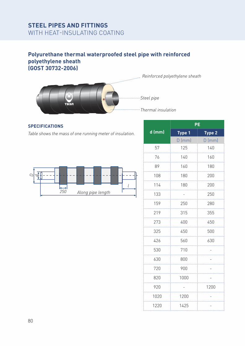
80
Polyurethane thermal waterproofed steel pipe with reinforced polyethylene sheath (GOST 30732-2006)
STEEL PIPES AND FITTINGS WITH HEAT-INSULATING COATING
SPECIFICATIONS
Table shows the mass of one running meter of insulation.
Reinforced polyethylene sheath
Steel pipe
Thermal insulation
d (mm)
PE
Type 1 Type 2
D (mm) D (mm)
57 125 140
76 140 160
89 160 180
108 180 200
114 180 200
133 - 250
159 250 280
219 315 355
273 400 450
325 450 500
426 560 630
530 710 -
630 800 -
720 900 -
820 1000 -
920 - 1200
1020 1200 -
1220 1425 -
Along pipe length
D d
l250
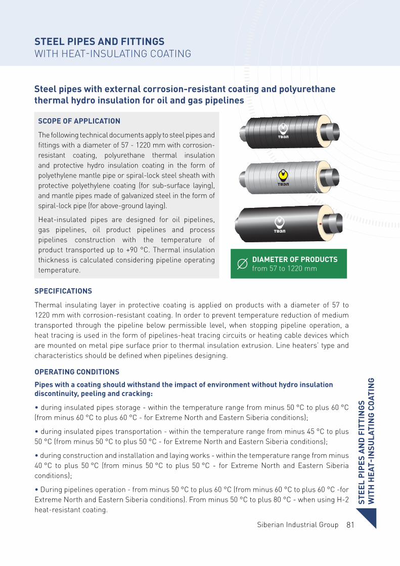
81Siberian Industrial Group
Steel pipes with external corrosion-resistant coating and polyurethane thermal hydro insulation for oil and gas pipelines
STEEL PIPES AND FITTINGS WITH HEAT-INSULATING COATING
DIAMETER OF PRODUCTS from 57 to 1220 mm
SCOPE OF APPLICATION
The following technical documents apply to steel pipes and fittings with a diameter of 57 - 1220 mm with corrosion-resistant coating, polyurethane thermal insulation and protective hydro insulation coating in the form of polyethylene mantle pipe or spiral-lock steel sheath with protective polyethylene coating (for sub-surface laying), and mantle pipes made of galvanized steel in the form of spiral-lock pipe (for above-ground laying).
Heat-insulated pipes are designed for oil pipelines, gas pipelines, oil product pipelines and process pipelines construction with the temperature of product transported up to +90 °C. Thermal insulation thickness is calculated considering pipeline operating temperature.
SPECIFICATIONS
Thermal insulating layer in protective coating is applied on products with a diameter of 57 to 1220 mm with corrosion-resistant coating. In order to prevent temperature reduction of medium transported through the pipeline below permissible level, when stopping pipeline operation, a heat tracing is used in the form of pipelines-heat tracing circuits or heating cable devices which are mounted on metal pipe surface prior to thermal insulation extrusion. Line heaters’ type and characteristics should be defined when pipelines designing.
OPERATING CONDITIONS
Pipes with a coating should withstand the impact of environment without hydro insulation discontinuity, peeling and cracking:
• during insulated pipes storage - within the temperature range from minus 50 °C to plus 60 °C (from minus 60 °С to plus 60 °С - for Extreme North and Eastern Siberia conditions);
• during insulated pipes transportation - within the temperature range from minus 45 °C to plus 50 °С (from minus 50 °С to plus 50 °С - for Extreme North and Eastern Siberia conditions);
• during construction and installation and laying works - within the temperature range from minus 40 °C to plus 50 °C (from minus 50 °C to plus 50 °C - for Extreme North and Eastern Siberia conditions);
• During pipelines operation - from minus 50 °C to plus 60 °C (from minus 60 °C to plus 60 °C -for Extreme North and Eastern Siberia conditions). From minus 50 °C to plus 80 °C - when using H-2 heat-resistant coating.
STEE
L PI
PES
AN
D F
ITTI
NG
S W
ITH
HEA
T-IN
SULA
TIN
G C
OAT
ING
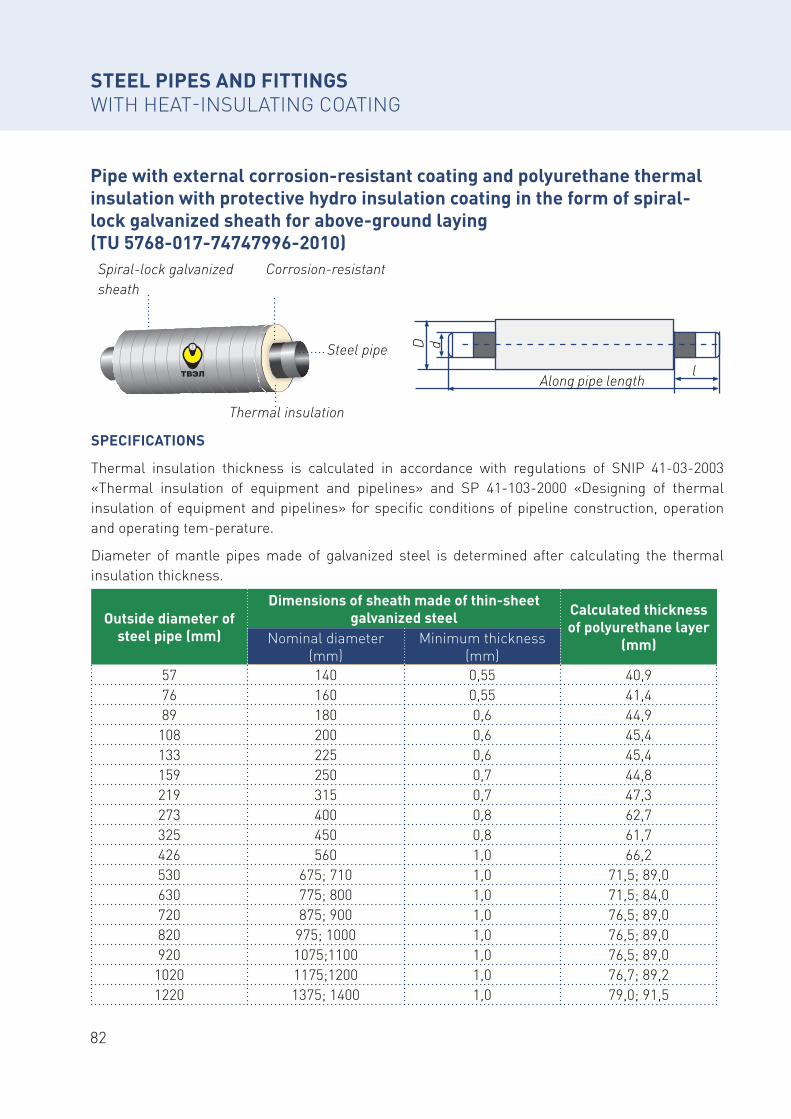
82
Pipe with external corrosion-resistant coating and polyurethane thermal insulation with protective hydro insulation coating in the form of spiral-lock galvanized sheath for above-ground laying (TU 5768-017-74747996-2010)
STEEL PIPES AND FITTINGS WITH HEAT-INSULATING COATING
SPECIFICATIONS
Thermal insulation thickness is calculated in accordance with regulations of SNIP 41-03-2003 «Thermal insulation of equipment and pipelines» and SP 41-103-2000 «Designing of thermal insulation of equipment and pipelines» for specific conditions of pipeline construction, operation and operating tem-perature.
Diameter of mantle pipes made of galvanized steel is determined after calculating the thermal insulation thickness.
Spiral-lock galvanized sheath
Corrosion-resistant
Thermal insulation
Steel pipe
Outside diameter of steel pipe (mm)
Dimensions of sheath made of thin-sheet galvanized steel Calculated thickness
of polyurethane layer (mm)Nominal diameter
(mm)Minimum thickness
(mm)57 140 0,55 40,976 160 0,55 41,489 180 0,6 44,9
108 200 0,6 45,4133 225 0,6 45,4159 250 0,7 44,8219 315 0,7 47,3273 400 0,8 62,7325 450 0,8 61,7426 560 1,0 66,2530 675; 710 1,0 71,5; 89,0630 775; 800 1,0 71,5; 84,0720 875; 900 1,0 76,5; 89,0820 975; 1000 1,0 76,5; 89,0920 1075;1100 1,0 76,5; 89,0
1020 1175;1200 1,0 76,7; 89,21220 1375; 1400 1,0 79,0; 91,5
Along pipe length
D d
l
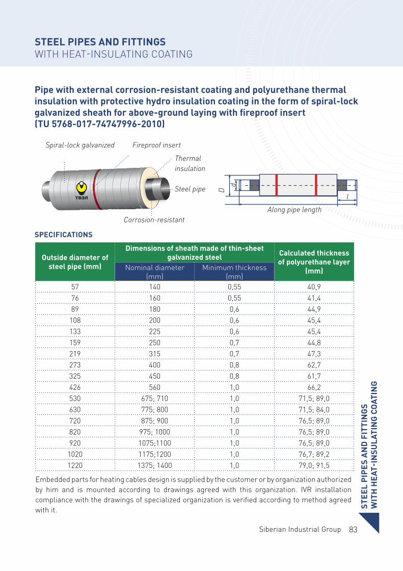
83Siberian Industrial Group
STEE
L PI
PES
AN
D F
ITTI
NG
S W
ITH
HEA
T-IN
SULA
TIN
G C
OAT
ING
Pipe with external corrosion-resistant coating and polyurethane thermal insulation with protective hydro insulation coating in the form of spiral-lock galvanized sheath for above-ground laying with fireproof insert (TU 5768-017-74747996-2010)
STEEL PIPES AND FITTINGS WITH HEAT-INSULATING COATING
SPECIFICATIONS
Embedded parts for heating cables design is supplied by the customer or by organization authorized by him and is mounted according to drawings agreed with this organization. IVR installation compliance with the drawings of specialized organization is verified according to method agreed with it.
Spiral-lock galvanized
Corrosion-resistant
Thermal insulation
Steel pipe
Fireproof insert
Along pipe lengthD
d
l
Outside diameter of steel pipe (mm)
Dimensions of sheath made of thin-sheet galvanized steel Calculated thickness
of polyurethane layer (mm)Nominal diameter
(mm)Minimum thickness
(mm)57 140 0,55 40,976 160 0,55 41,489 180 0,6 44,9
108 200 0,6 45,4133 225 0,6 45,4159 250 0,7 44,8219 315 0,7 47,3273 400 0,8 62,7325 450 0,8 61,7426 560 1,0 66,2530 675; 710 1,0 71,5; 89,0630 775; 800 1,0 71,5; 84,0720 875; 900 1,0 76,5; 89,0820 975; 1000 1,0 76,5; 89,0920 1075;1100 1,0 76,5; 89,0
1020 1175;1200 1,0 76,7; 89,21220 1375; 1400 1,0 79,0; 91,5
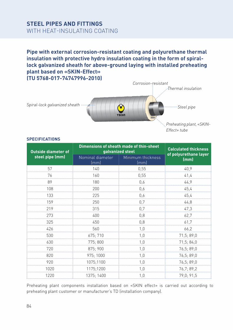
84
Pipe with external corrosion-resistant coating and polyurethane thermal insulation with protective hydro insulation coating in the form of spiral-lock galvanized sheath for above-ground laying with installed preheating plant based on «SKIN-Effect» (TU 5768-017-74747996-2010)
SPECIFICATIONS
Preheating plant components installation based on «SKIN effect» is carried out according to preheating plant customer or manufacturer’s TD (installation company).
Spiral-lock galvanized sheath
Corrosion-resistantThermal insulation
Preheating plant, «SKIN-Effect» tube
Steel pipe
Outside diameter of steel pipe (mm)
Dimensions of sheath made of thin-sheet galvanized steel Calculated thickness
of polyurethane layer (mm)Nominal diameter
(mm)Minimum thickness
(mm)57 140 0,55 40,976 160 0,55 41,489 180 0,6 44,9
108 200 0,6 45,4133 225 0,6 45,4159 250 0,7 44,8219 315 0,7 47,3273 400 0,8 62,7325 450 0,8 61,7426 560 1,0 66,2530 675; 710 1,0 71,5; 89,0630 775; 800 1,0 71,5; 84,0720 875; 900 1,0 76,5; 89,0820 975; 1000 1,0 76,5; 89,0920 1075;1100 1,0 76,5; 89,0
1020 1175;1200 1,0 76,7; 89,21220 1375; 1400 1,0 79,0; 91,5
STEEL PIPES AND FITTINGS WITH HEAT-INSULATING COATING
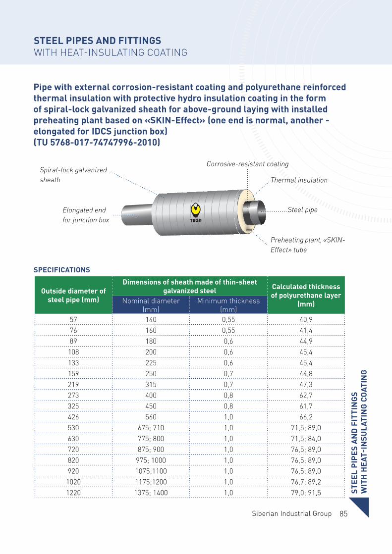
85Siberian Industrial Group
Pipe with external corrosion-resistant coating and polyurethane reinforced thermal insulation with protective hydro insulation coating in the form of spiral-lock galvanized sheath for above-ground laying with installed preheating plant based on «SKIN-Effect» (one end is normal, another - elongated for IDCS junction box) (TU 5768-017-74747996-2010)
SPECIFICATIONS
Spiral-lock galvanized sheath
Elongated end for junction box
Сorrosive-resistant coating
Thermal insulation
Preheating plant, «SKIN-Effect» tube
Steel pipe
Outside diameter of steel pipe (mm)
Dimensions of sheath made of thin-sheet galvanized steel Calculated thickness
of polyurethane layer (mm)Nominal diameter
(mm)Minimum thickness
(mm)57 140 0,55 40,976 160 0,55 41,489 180 0,6 44,9
108 200 0,6 45,4133 225 0,6 45,4159 250 0,7 44,8219 315 0,7 47,3273 400 0,8 62,7325 450 0,8 61,7426 560 1,0 66,2530 675; 710 1,0 71,5; 89,0630 775; 800 1,0 71,5; 84,0720 875; 900 1,0 76,5; 89,0820 975; 1000 1,0 76,5; 89,0920 1075;1100 1,0 76,5; 89,0
1020 1175;1200 1,0 76,7; 89,21220 1375; 1400 1,0 79,0; 91,5 STEE
L PI
PES
AN
D F
ITTI
NG
S W
ITH
HEA
T-IN
SULA
TIN
G C
OAT
ING
STEEL PIPES AND FITTINGS WITH HEAT-INSULATING COATING
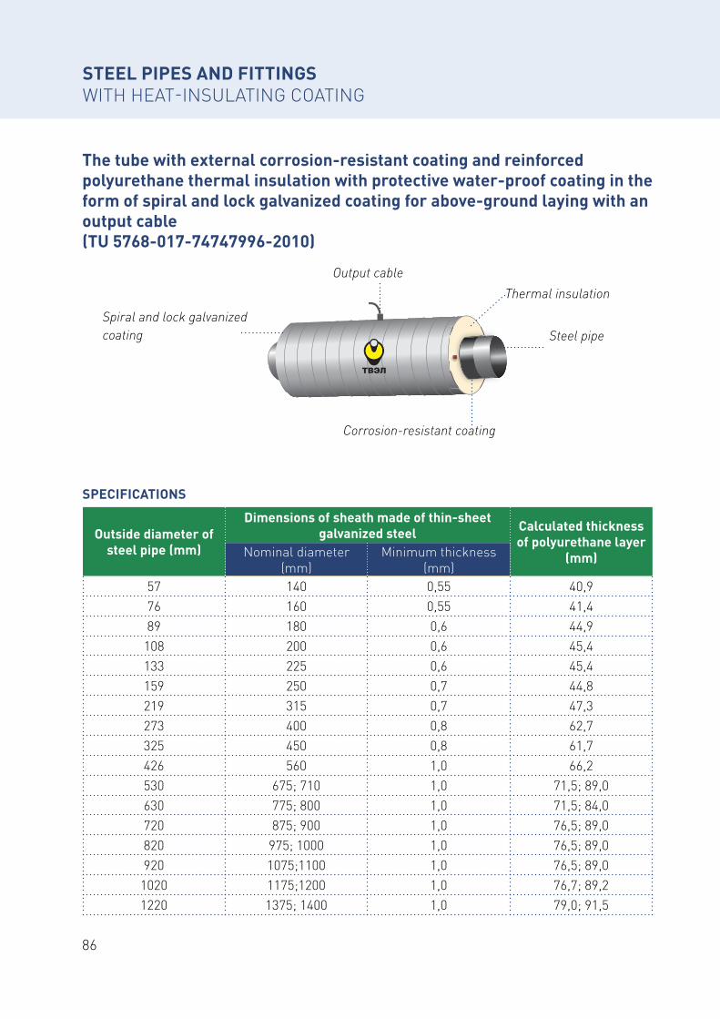
86
The tube with external corrosion-resistant coating and reinforced polyurethane thermal insulation with protective water-proof coating in the form of spiral and lock galvanized coating for above-ground laying with an output cable (TU 5768-017-74747996-2010)
SPECIFICATIONS
Spiral and lock galvanized coating
Corrosion-resistant coating
Thermal insulationOutput cable
Steel pipe
Outside diameter of steel pipe (mm)
Dimensions of sheath made of thin-sheet galvanized steel Calculated thickness
of polyurethane layer (mm)Nominal diameter
(mm)Minimum thickness
(mm)57 140 0,55 40,976 160 0,55 41,489 180 0,6 44,9
108 200 0,6 45,4133 225 0,6 45,4159 250 0,7 44,8219 315 0,7 47,3273 400 0,8 62,7325 450 0,8 61,7426 560 1,0 66,2530 675; 710 1,0 71,5; 89,0630 775; 800 1,0 71,5; 84,0720 875; 900 1,0 76,5; 89,0820 975; 1000 1,0 76,5; 89,0920 1075;1100 1,0 76,5; 89,0
1020 1175;1200 1,0 76,7; 89,21220 1375; 1400 1,0 79,0; 91,5
STEEL PIPES AND FITTINGS WITH HEAT-INSULATING COATING
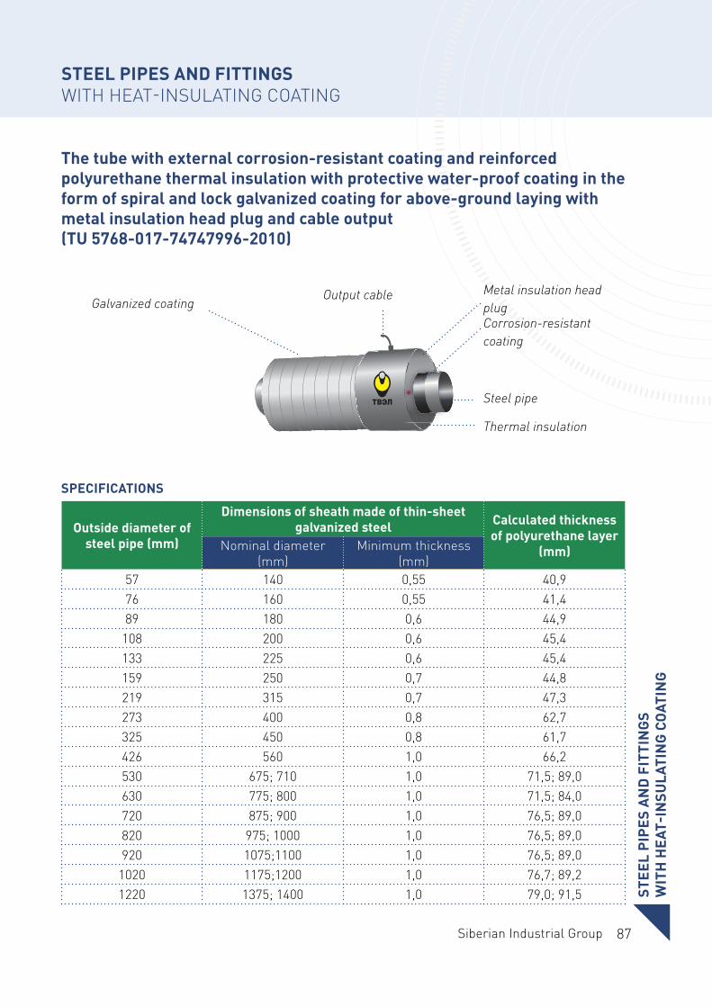
87Siberian Industrial Group
Outside diameter of steel pipe (mm)
Dimensions of sheath made of thin-sheet galvanized steel Calculated thickness
of polyurethane layer (mm)Nominal diameter
(mm)Minimum thickness
(mm)57 140 0,55 40,976 160 0,55 41,489 180 0,6 44,9
108 200 0,6 45,4133 225 0,6 45,4159 250 0,7 44,8219 315 0,7 47,3273 400 0,8 62,7325 450 0,8 61,7426 560 1,0 66,2530 675; 710 1,0 71,5; 89,0630 775; 800 1,0 71,5; 84,0720 875; 900 1,0 76,5; 89,0820 975; 1000 1,0 76,5; 89,0920 1075;1100 1,0 76,5; 89,0
1020 1175;1200 1,0 76,7; 89,21220 1375; 1400 1,0 79,0; 91,5
The tube with external corrosion-resistant coating and reinforced polyurethane thermal insulation with protective water-proof coating in the form of spiral and lock galvanized coating for above-ground laying with metal insulation head plug and cable output (TU 5768-017-74747996-2010)
SPECIFICATIONS
Galvanized coating Output cable
Thermal insulation
Metal insulation head plugCorrosion-resistant coating
Steel pipe
STEE
L PI
PES
AN
D F
ITTI
NG
S W
ITH
HEA
T-IN
SULA
TIN
G C
OAT
ING
STEEL PIPES AND FITTINGS WITH HEAT-INSULATING COATING
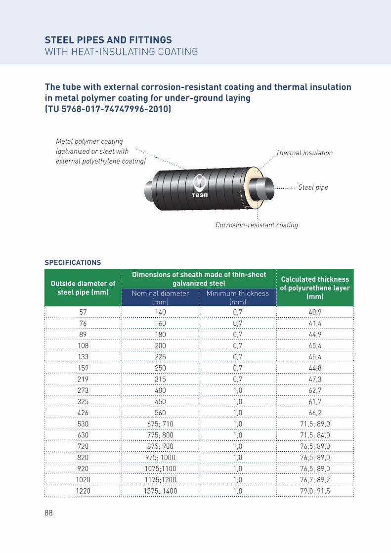
88
The tube with external corrosion-resistant coating and thermal insulation in metal polymer coating for under-ground laying (TU 5768-017-74747996-2010)
SPECIFICATIONS
Metal polymer coating (galvanized or steel with external polyethylene coating)
Corrosion-resistant coating
Thermal insulation
Steel pipe
Outside diameter of steel pipe (mm)
Dimensions of sheath made of thin-sheet galvanized steel Calculated thickness
of polyurethane layer (mm)Nominal diameter
(mm)Minimum thickness
(mm)57 140 0,7 40,976 160 0,7 41,489 180 0,7 44,9
108 200 0,7 45,4133 225 0,7 45,4159 250 0,7 44,8219 315 0,7 47,3273 400 1,0 62,7325 450 1,0 61,7426 560 1,0 66,2530 675; 710 1,0 71,5; 89,0630 775; 800 1,0 71,5; 84,0720 875; 900 1,0 76,5; 89,0820 975; 1000 1,0 76,5; 89,0920 1075;1100 1,0 76,5; 89,0
1020 1175;1200 1,0 76,7; 89,21220 1375; 1400 1,0 79,0; 91,5
STEEL PIPES AND FITTINGS WITH HEAT-INSULATING COATING
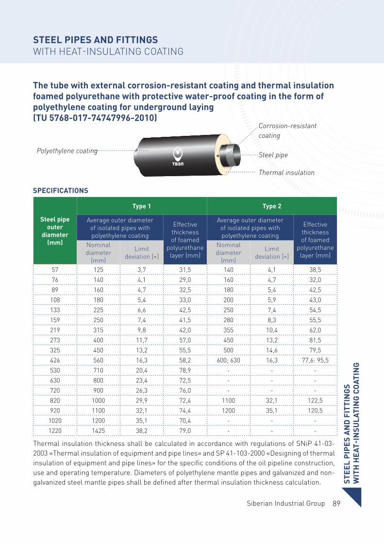
89Siberian Industrial Group
The tube with external corrosion-resistant coating and thermal insulation foamed polyurethane with protective water-proof coating in the form of polyethylene coating for underground laying (TU 5768-017-74747996-2010)
SPECIFICATIONS
Polyethylene coating
Thermal insulation
Corrosion-resistant coating
Steel pipe
Steel pipe outer
diameter (mm)
Type 1 Type 2
Average outer diameter of isolated pipes with polyethylene coating
Effective thickness of foamed
polyurethane layer (mm)
Average outer diameter of isolated pipes with polyethylene coating
Effective thickness of foamed
polyurethane layer (mm)
Nominal diameter
(mm)
Limit deviation [+]
Nominal diameter
(mm)
Limit deviation [+]
57 125 3,7 31,5 140 4,1 38,576 140 4,1 29,0 160 4,7 32,089 160 4,7 32,5 180 5,4 42,5
108 180 5,4 33,0 200 5,9 43,0133 225 6,6 42,5 250 7,4 54,5159 250 7,4 41,5 280 8,3 55,5219 315 9,8 42,0 355 10,4 62,0273 400 11,7 57,0 450 13,2 81,5325 450 13,2 55,5 500 14,6 79,5426 560 16,3 58,2 600; 630 16,3 77,6: 95,5530 710 20,4 78,9 - - -630 800 23,4 72,5 - - -720 900 26,3 76,0 - - -820 1000 29,9 72,4 1100 32,1 122,5920 1100 32,1 74,4 1200 35,1 120,5
1020 1200 35,1 70,4 - - -1220 1425 38,2 79,0 - - -
Thermal insulation thickness shall be calculated in accordance with regulations of SNiP 41-03-2003 «Thermal insulation of equipment and pipe lines» and SP 41-103-2000 «Designing of thermal insulation of equipment and pipe lines» for the specific conditions of the oil pipeline construction, use and operating temperature. Diameters of polyethylene mantle pipes and galvanized and non-galvanized steel mantle pipes shall be defined after thermal insulation thickness calculation. ST
EEL
PIPE
S A
ND
FIT
TIN
GS
WIT
H H
EAT-
INSU
LATI
NG
CO
ATIN
G
STEEL PIPES AND FITTINGS WITH HEAT-INSULATING COATING
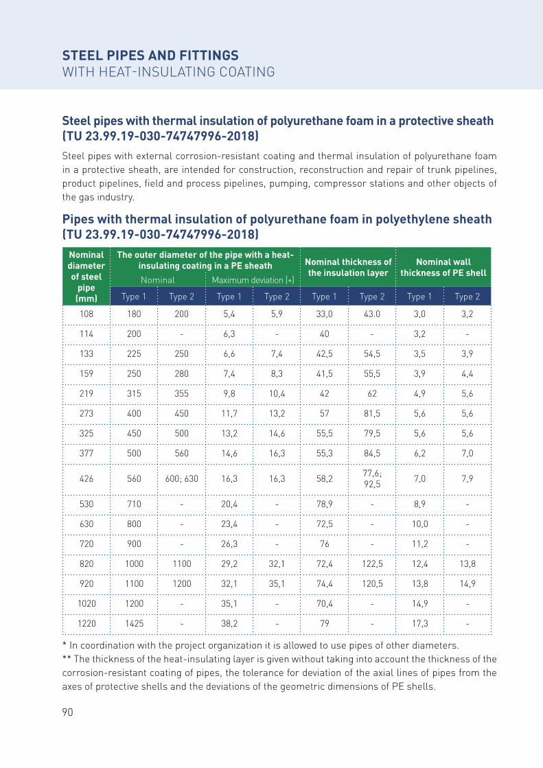
90
Steel pipes with thermal insulation of polyurethane foam in a protective sheath (TU 23.99.19-030-74747996-2018)Steel pipes with external corrosion-resistant coating and thermal insulation of polyurethane foam in a protective sheath, are intended for construction, reconstruction and repair of trunk pipelines, product pipelines, field and process pipelines, pumping, compressor stations and other objects of the gas industry.
Pipes with thermal insulation of polyurethane foam in polyethylene sheath (TU 23.99.19-030-74747996-2018)
Nominal diameter of steel
pipe (mm)
The outer diameter of the pipe with a heat-insulating coating in a PE sheath Nominal thickness of
the insulation layer Nominal wall
thickness of PE shellNominal Maximum deviation (+)
Type 1 Type 2 Type 1 Type 2 Type 1 Type 2 Type 1 Type 2
108 180 200 5,4 5,9 33,0 43.0 3,0 3,2
114 200 - 6,3 - 40 - 3,2 -
133 225 250 6,6 7,4 42,5 54,5 3,5 3,9
159 250 280 7,4 8,3 41,5 55,5 3,9 4,4
219 315 355 9,8 10,4 42 62 4,9 5,6
273 400 450 11,7 13,2 57 81,5 5,6 5,6
325 450 500 13,2 14,6 55,5 79,5 5,6 5,6
377 500 560 14,6 16,3 55,3 84,5 6,2 7,0
426 560 600; 630 16,3 16,3 58,2 77,6; 92,5 7,0 7,9
530 710 - 20,4 - 78,9 - 8,9 -
630 800 - 23,4 - 72,5 - 10,0 -
720 900 - 26,3 - 76 - 11,2 -
820 1000 1100 29,2 32,1 72,4 122,5 12,4 13,8
920 1100 1200 32,1 35,1 74,4 120,5 13,8 14,9
1020 1200 - 35,1 - 70,4 - 14,9 -
1220 1425 - 38,2 - 79 - 17,3 -
* In coordination with the project organization it is allowed to use pipes of other diameters.** The thickness of the heat-insulating layer is given without taking into account the thickness of the corrosion-resistant coating of pipes, the tolerance for deviation of the axial lines of pipes from the axes of protective shells and the deviations of the geometric dimensions of PE shells.
STEEL PIPES AND FITTINGS WITH HEAT-INSULATING COATING
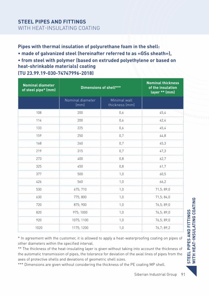
91Siberian Industrial Group
Pipes with thermal insulation of polyurethane foam in the shell:• made of galvanized steel (hereinafter referred to as «GSs sheath»),• from steel with polymer (based on extruded polyethylene or based on heat-shrinkable materials) coating(TU 23.99.19-030-74747996-2018)
Nominal diameter of steel pipe* (mm) Dimensions of shell***
Nominal thickness of the insulation
layer ** (mm)
Nominal diameter (mm)
Minimal wall thickness (mm)
108 200 0,6 45,4
114 200 0,6 42,4
133 225 0,6 45,4
159 250 0,7 44,8
168 260 0,7 45,3
219 315 0,7 47,3
273 400 0,8 62,7
325 450 0,8 61,7
377 500 1,0 60,5
426 560 1,0 66,2
530 675; 710 1,0 71,5; 89,0
630 775; 800 1,0 71,5; 84,0
720 875; 900 1,0 76,5; 89,0
820 975; 1000 1,0 76,5; 89,0
920 1075; 1100 1,0 76,5; 89,0
1020 1175; 1200 1,0 76,7; 89,2
* In agreement with the customer, it is allowed to apply a heat-waterproofing coating on pipes of other diameters within the specified interval.** The thickness of the heat-insulating layer is given without taking into account the thickness of the automatic transmission of pipes, the tolerance for deviation of the axial lines of pipes from the axes of protective shells and deviations of geometric shell sizes.*** Dimensions are given without considering the thickness of the PE coating MP shell. ST
EEL
PIPE
S A
ND
FIT
TIN
GS
WIT
H H
EAT-
INSU
LATI
NG
CO
ATIN
G
STEEL PIPES AND FITTINGS WITH HEAT-INSULATING COATING
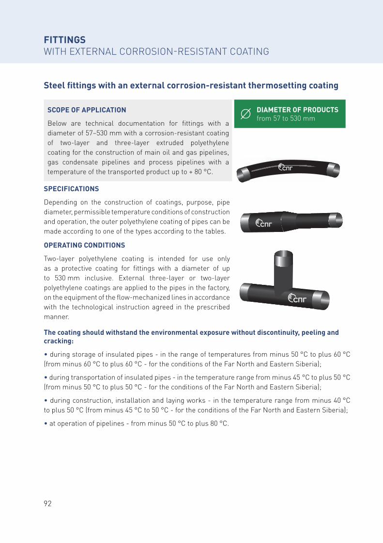
92
Steel fittings with an external corrosion-resistant thermosetting coating
FITTINGS WITH EXTERNAL CORROSION-RESISTANT COATING
The coating should withstand the environmental exposure without discontinuity, peeling and cracking:
• during storage of insulated pipes - in the range of temperatures from minus 50 °С to plus 60 °С (from minus 60 °С to plus 60 °С - for the conditions of the Far North and Eastern Siberia);
• during transportation of insulated pipes - in the temperature range from minus 45 °С to plus 50 °С (from minus 50 °С to plus 50 °С - for the conditions of the Far North and Eastern Siberia);
• during construction, installation and laying works - in the temperature range from minus 40 °С to plus 50 °С (from minus 45 °С to 50 °С - for the conditions of the Far North and Eastern Siberia);
• at operation of pipelines - from minus 50 °С to plus 80 °C.
DIAMETER OF PRODUCTS from 57 to 530 mm
SCOPE OF APPLICATION
Below are technical documentation for fittings with a diameter of 57–530 mm with a corrosion-resistant coating of two-layer and three-layer extruded polyethylene coating for the construction of main oil and gas pipelines, gas condensate pipelines and process pipelines with a temperature of the transported product up to + 80 °C.
SPECIFICATIONS
Depending on the construction of coatings, purpose, pipe diameter, permissible temperature conditions of construction and operation, the outer polyethylene coating of pipes can be made according to one of the types according to the tables.
OPERATING CONDITIONS
Two-layer polyethylene coating is intended for use only as a protective coating for fittings with a diameter of up to 530 mm inclusive. External three-layer or two-layer polyethylene coatings are applied to the pipes in the factory, on the equipment of the flow-mechanized lines in accordance with the technological instruction agreed in the prescribed manner.
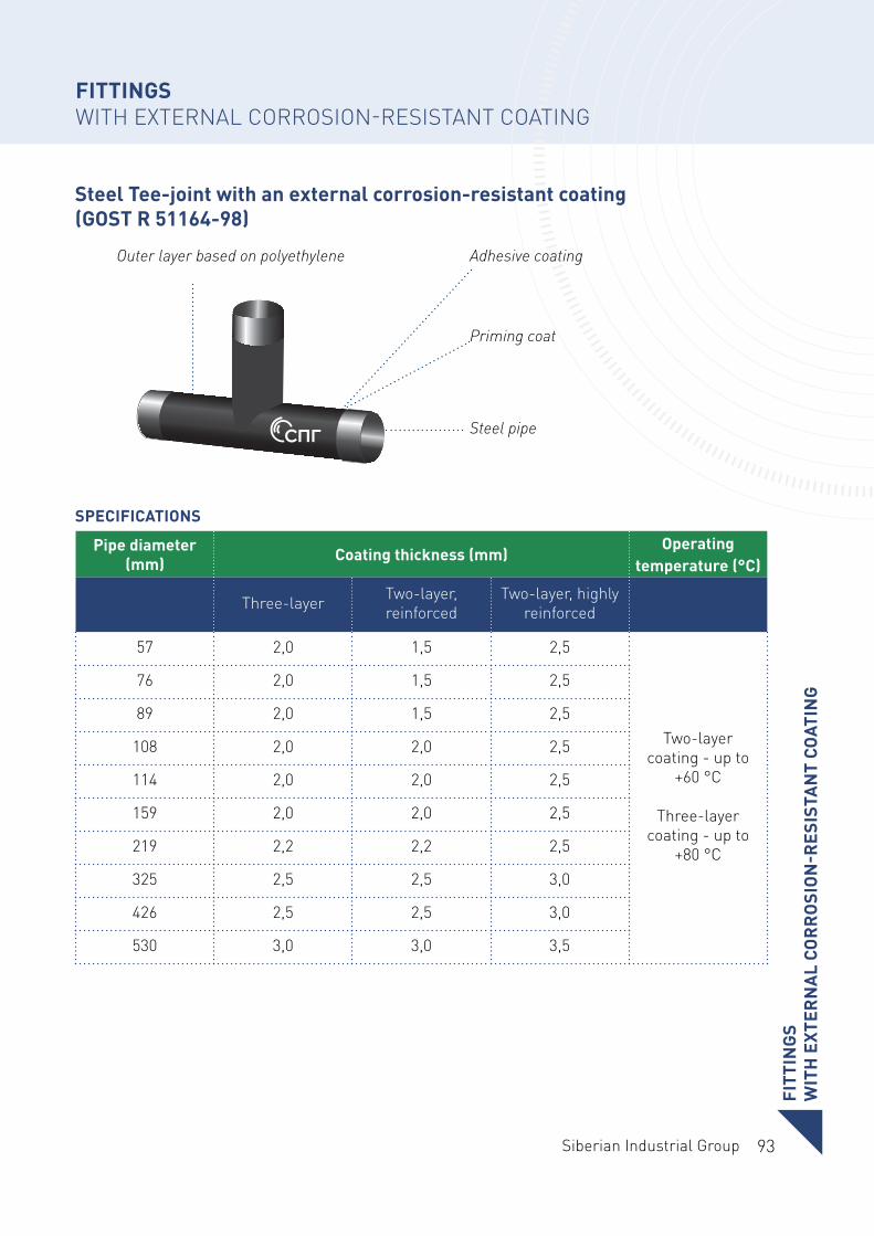
93Siberian Industrial Group
FITT
ING
S W
ITH
EXT
ERN
AL
COR
RO
SIO
N-R
ESIS
TAN
T CO
ATIN
G
SPECIFICATIONS
Steel Tee-joint with an external corrosion-resistant coating (GOST R 51164-98)
Pipe diameter (mm) Coating thickness (mm)
Operating temperature (°C)
Three-layer Two-layer, reinforced
Two-layer, highly reinforced
57 2,0 1,5 2,5
Two-layer coating - up to
+60 °C
Three-layer coating - up to
+80 °C
76 2,0 1,5 2,5
89 2,0 1,5 2,5
108 2,0 2,0 2,5
114 2,0 2,0 2,5
159 2,0 2,0 2,5
219 2,2 2,2 2,5
325 2,5 2,5 3,0
426 2,5 2,5 3,0
530 3,0 3,0 3,5
FITTINGS WITH EXTERNAL CORROSION-RESISTANT COATING
Outer layer based on polyethylene
Priming coat
Adhesive coating
Steel pipe
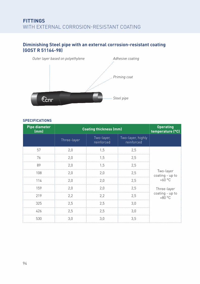
94
SPECIFICATIONS
Diminishing Steel pipe with an external corrosion-resistant coating (GOST R 51164-98)
Pipe diameter (mm) Coating thickness (mm) Operating
temperature (°C)
Three-layer Two-layer, reinforced
Two-layer, highly reinforced
57 2,0 1,5 2,5
Two-layer coating - up to
+60 °C
Three-layer coating - up to
+80 °C
76 2,0 1,5 2,5
89 2,0 1,5 2,5
108 2,0 2,0 2,5
114 2,0 2,0 2,5
159 2,0 2,0 2,5
219 2,2 2,2 2,5
325 2,5 2,5 3,0
426 2,5 2,5 3,0
530 3,0 3,0 3,5
FITTINGS WITH EXTERNAL CORROSION-RESISTANT COATING
Outer layer based on polyethylene
Priming coat
Adhesive coating
Steel pipe
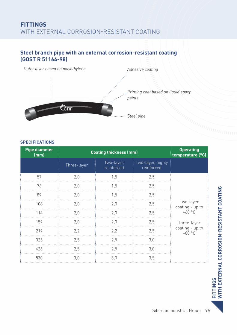
95Siberian Industrial Group
FITT
ING
S W
ITH
EXT
ERN
AL
COR
RO
SIO
N-R
ESIS
TAN
T CO
ATIN
G
SPECIFICATIONS
Steel branch pipe with an external corrosion-resistant coating (GOST R 51164-98)
Pipe diameter (mm) Coating thickness (mm) Operating
temperature (°C)
Three-layer Two-layer, reinforced
Two-layer, highly reinforced
57 2,0 1,5 2,5
Two-layer coating - up to
+60 °C
Three-layer coating - up to
+80 °C
76 2,0 1,5 2,5
89 2,0 1,5 2,5
108 2,0 2,0 2,5
114 2,0 2,0 2,5
159 2,0 2,0 2,5
219 2,2 2,2 2,5
325 2,5 2,5 3,0
426 2,5 2,5 3,0
530 3,0 3,0 3,5
Outer layer based on polyethylene
Priming coat based on liquid epoxy paints
Adhesive coating
Steel pipe
FITTINGS WITH EXTERNAL CORROSION-RESISTANT COATING
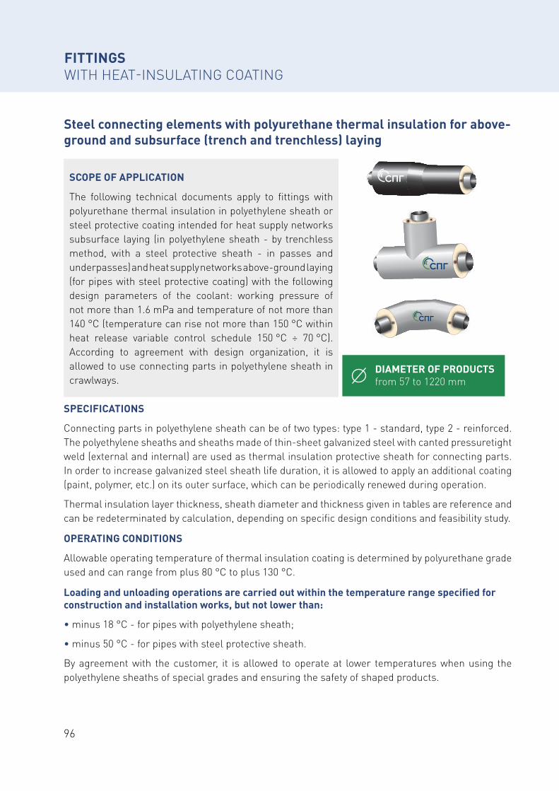
96
Steel connecting elements with polyurethane thermal insulation for above-ground and subsurface (trench and trenchless) laying
FITTINGS WITH HEAT-INSULATING COATING
DIAMETER OF PRODUCTS from 57 to 1220 mm
SCOPE OF APPLICATION
The following technical documents apply to fittings with polyurethane thermal insulation in polyethylene sheath or steel protective coating intended for heat supply networks subsurface laying (in polyethylene sheath - by trenchless method, with a steel protective sheath - in passes and underpasses) and heat supply networks above-ground laying (for pipes with steel protective coating) with the following design parameters of the coolant: working pressure of not more than 1.6 mPa and temperature of not more than 140 °C (temperature can rise not more than 150 °С within heat release variable control schedule 150 °С ÷ 70 °С). According to agreement with design organization, it is allowed to use connecting parts in polyethylene sheath in crawlways.
SPECIFICATIONS
Connecting parts in polyethylene sheath can be of two types: type 1 - standard, type 2 - reinforced. The polyethylene sheaths and sheaths made of thin-sheet galvanized steel with canted pressuretight weld (external and internal) are used as thermal insulation protective sheath for connecting parts. In order to increase galvanized steel sheath life duration, it is allowed to apply an additional coating (paint, polymer, etc.) on its outer surface, which can be periodically renewed during operation.
Thermal insulation layer thickness, sheath diameter and thickness given in tables are reference and can be redeterminated by calculation, depending on specific design conditions and feasibility study.
OPERATING CONDITIONS
Allowable operating temperature of thermal insulation coating is determined by polyurethane grade used and can range from plus 80 °C to plus 130 °C.
Loading and unloading operations are carried out within the temperature range specified for construction and installation works, but not lower than:
• minus 18 °C - for pipes with polyethylene sheath;
• minus 50 °C - for pipes with steel protective sheath.
By agreement with the customer, it is allowed to operate at lower temperatures when using the polyethylene sheaths of special grades and ensuring the safety of shaped products.
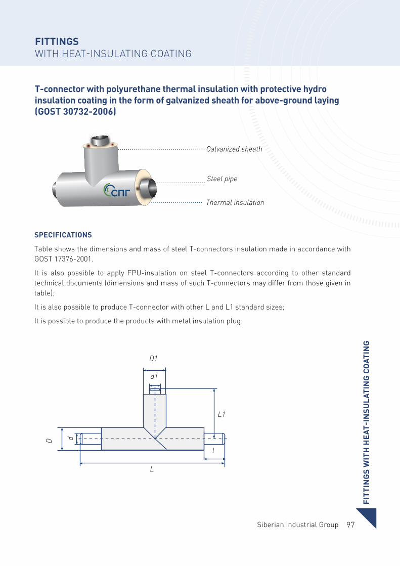
97Siberian Industrial Group
FITT
ING
S W
ITH
HEA
T-IN
SULA
TIN
G C
OAT
ING
T-connector with polyurethane thermal insulation with protective hydro insulation coating in the form of galvanized sheath for above-ground laying (GOST 30732-2006)
FITTINGS WITH HEAT-INSULATING COATING
SPECIFICATIONS
Table shows the dimensions and mass of steel T-connectors insulation made in accordance with GOST 17376-2001.
It is also possible to apply FPU-insulation on steel T-connectors according to other standard technical documents (dimensions and mass of such T-connectors may differ from those given in table);
It is also possible to produce T-connector with other L and L1 standard sizes;
It is possible to produce the products with metal insulation plug.
L
D
D1
L1
d
d1
l
Galvanized sheath
Steel pipe
Thermal insulation
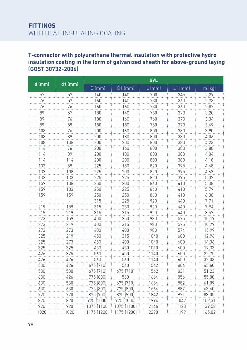
98
d (mm) d1 (mm)GVL
D (mm) D1 (mm) L (mm) L1 (mm) m (kg)57 57 140 140 700 345 2,2976 57 160 140 730 360 2,7376 76 160 160 730 360 2,8789 57 180 140 760 370 3,2089 76 180 160 760 370 3,3489 89 180 180 760 370 3,49
108 76 200 160 800 380 3,90108 89 200 180 800 380 4,06108 108 200 200 800 380 4,23114 76 200 160 800 380 3,88114 89 200 180 800 380 4,04114 114 200 200 800 380 4,18133 89 225 180 820 395 4,48133 108 225 200 820 395 4,63133 133 225 225 820 395 5,02159 108 250 200 860 410 5,38159 133 250 225 860 410 5,79159 159 250 250 860 410 6,00
- - 315 225 920 440 7,71219 159 315 250 920 440 7,94219 219 315 315 920 440 8,57273 159 400 250 980 575 10,19273 219 400 315 980 575 10,79273 273 400 400 980 574 15,99325 219 450 315 1040 600 12,96325 273 450 400 1040 600 14,36325 325 450 450 1040 600 19,33426 325 560 450 1140 650 22,75426 426 560 560 1140 650 32,03530 426 675 (710) 560 1562 806 45,60530 530 675 (710) 675 (710) 1562 831 51,23630 426 775 (800) 560 1664 856 55,00630 530 775 (800) 675 (710) 1664 882 61,09630 630 775 (800) 775 (800) 1664 882 63,40720 720 875 (900) 875 (900) 1842 971 83,05820 820 975 (1000) 975 (1000) 1994 1047 102,31920 920 1075 (1100) 1075 (1100) 2146 1123 139,58
1020 1020 1175 (1200) 1175 (1200) 2298 1199 165,82
T-connector with polyurethane thermal insulation with protective hydro insulation coating in the form of galvanized sheath for above-ground laying (GOST 30732-2006)
FITTINGS WITH HEAT-INSULATING COATING
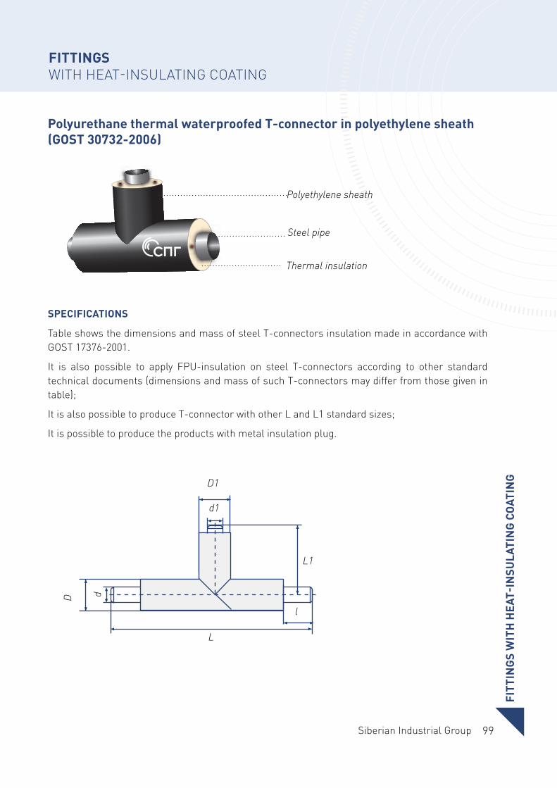
99Siberian Industrial Group
Polyurethane thermal waterproofed T-connector in polyethylene sheath (GOST 30732-2006)
SPECIFICATIONS
Table shows the dimensions and mass of steel T-connectors insulation made in accordance with GOST 17376-2001.
It is also possible to apply FPU-insulation on steel T-connectors according to other standard technical documents (dimensions and mass of such T-connectors may differ from those given in table);
It is also possible to produce T-connector with other L and L1 standard sizes;
It is possible to produce the products with metal insulation plug.
L
D
D1
L1
d
d1
l
Polyethylene sheath
Steel pipe
Thermal insulation
FITT
ING
S W
ITH
HEA
T-IN
SULA
TIN
G C
OAT
ING
FITTINGS WITH HEAT-INSULATING COATING
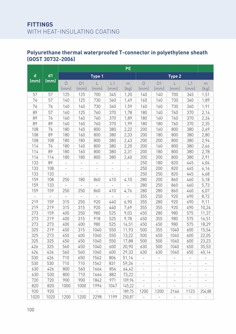
100
Polyurethane thermal waterproofed T-connector in polyethylene sheath (GOST 30732-2006)
d (mm)
d1 (mm)
PE
Тype 1 Тype 2
D (mm)
D1 (mm)
L (mm)
L1 (mm)
m (kg)
D (mm)
D1 (mm)
L (mm)
L1 (mm)
m (kg)
57 57 125 125 700 345 1,20 140 140 700 345 1,5176 57 140 125 730 360 1,49 160 140 730 360 1,8976 76 140 140 730 360 1,59 160 160 730 360 1,9189 57 160 125 760 370 1,78 180 140 760 370 2,1489 76 160 140 760 370 1,89 180 160 760 370 2,2489 89 160 160 760 370 1,99 180 180 760 370 2,35
108 76 180 140 800 380 2,22 200 160 800 380 2,69108 89 180 160 800 380 2,33 200 180 800 380 2,80108 108 180 180 800 380 2,43 200 200 800 380 2,94114 76 180 140 800 380 2,20 200 160 800 380 2,66114 89 180 160 800 380 2,31 200 180 800 380 2,78114 114 180 180 800 380 2,40 200 200 800 380 2,91133 89 - - - - - 250 180 820 445 4,04133 108 - - - - - 250 200 820 445 4,16133 133 - - - - - 250 250 820 445 4,68159 108 250 180 860 410 4,10 280 200 860 460 5,18159 133 - - - - - 280 250 860 460 5,73159 159 250 250 860 410 4,76 280 280 860 460 6,07
- - - - - - - 355 250 920 490 8,72219 159 315 250 920 440 6,90 355 280 920 490 9,11219 219 315 315 920 440 7,69 355 355 920 490 10,24273 159 400 250 980 525 9,03 450 280 980 575 11,37273 219 400 315 918 525 9,78 450 355 980 575 16,51273 273 400 400 980 525 14,51 450 450 980 575 18,29325 219 450 315 1040 550 11,93 500 355 1040 600 15,54325 273 450 400 1040 550 13,22 500 450 1040 600 22,05325 325 450 450 1040 550 17,88 500 500 1040 600 23,23426 325 560 450 1040 600 20,90 630 500 1040 650 35,53426 426 560 560 1040 600 29,33 630 630 1040 650 40,14530 426 710 650 1562 806 51,14 - - - - -530 530 710 710 1562 831 59,26 - - - - -630 426 800 560 1664 856 64,42 - - - - -630 530 800 710 1664 882 73,22 - - - - -720 720 900 900 1842 971 109,96 - - - - -820 820 1000 1000 1994 1047 145,22 - - - - -
920 920 - - - - 189,75 1200 1200 2146 1123 254,881020 1020 1200 1200 2298 1199 250,87 - - - - -
FITTINGS WITH HEAT-INSULATING COATING
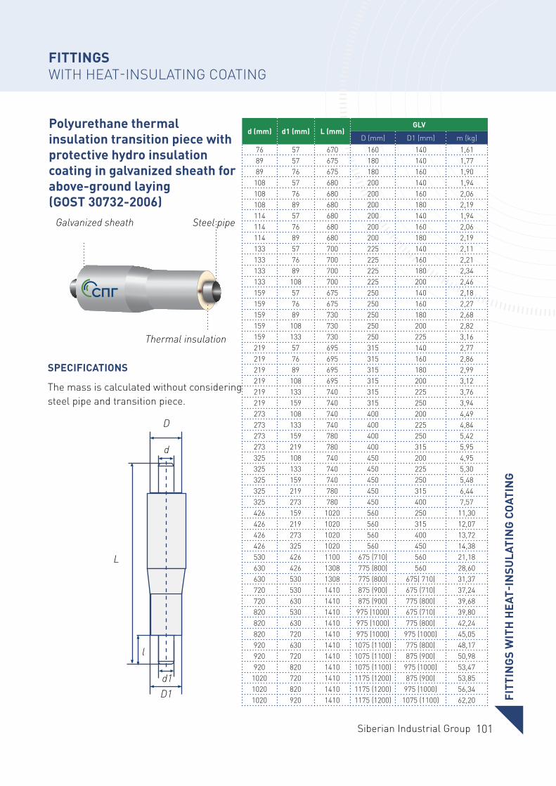
101Siberian Industrial Group
Polyurethane thermal insulation transition piece with protective hydro insulation coating in galvanized sheath for above-ground laying (GOST 30732-2006)
SPECIFICATIONS
The mass is calculated without considering steel pipe and transition piece.
d (mm) d1 (mm) L (mm)GLV
D (mm) D1 (mm) m (kg)76 57 670 160 140 1,6189 57 675 180 140 1,7789 76 675 180 160 1,90
108 57 680 200 140 1,94108 76 680 200 160 2,06108 89 680 200 180 2,19114 57 680 200 140 1,94114 76 680 200 160 2,06114 89 680 200 180 2,19133 57 700 225 140 2,11133 76 700 225 160 2,21133 89 700 225 180 2,34133 108 700 225 200 2,46159 57 675 250 140 2,18159 76 675 250 160 2,27159 89 730 250 180 2,68159 108 730 250 200 2,82159 133 730 250 225 3,16219 57 695 315 140 2,77219 76 695 315 160 2,86219 89 695 315 180 2,99219 108 695 315 200 3,12219 133 740 315 225 3,76219 159 740 315 250 3,94273 108 740 400 200 4,49273 133 740 400 225 4,84273 159 780 400 250 5,42273 219 780 400 315 5,95325 108 740 450 200 4,95325 133 740 450 225 5,30325 159 740 450 250 5,48325 219 780 450 315 6,44325 273 780 450 400 7,57426 159 1020 560 250 11,30426 219 1020 560 315 12,07426 273 1020 560 400 13,72426 325 1020 560 450 14,38530 426 1100 675 (710) 560 21,18630 426 1308 775 (800) 560 28,60630 530 1308 775 (800) 675( 710) 31,37720 530 1410 875 (900) 675 (710) 37,24720 630 1410 875 (900) 775 (800) 39,68820 530 1410 975 (1000) 675 (710) 39,80820 630 1410 975 (1000) 775 (800) 42,24820 720 1410 975 (1000) 975 (1000) 45,05920 630 1410 1075 (1100) 775 (800) 48,17920 720 1410 1075 (1100) 875 (900) 50,98920 820 1410 1075 (1100) 975 (1000) 53,47
1020 720 1410 1175 (1200) 875 (900) 53,851020 820 1410 1175 (1200) 975 (1000) 56,341020 920 1410 1175 (1200) 1075 (1100) 62,20
L
D
D1
d
d1
l
Galvanized sheath Steel pipe
Thermal insulation
FITT
ING
S W
ITH
HEA
T-IN
SULA
TIN
G C
OAT
ING
FITTINGS WITH HEAT-INSULATING COATING
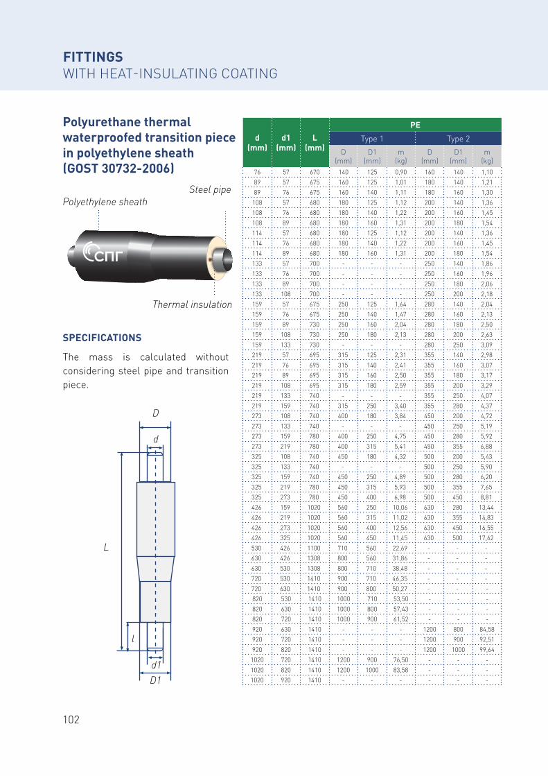
102
SPECIFICATIONS
The mass is calculated without considering steel pipe and transition piece.
L
D
D1
d
d1
l
d (mm)
d1 (mm)
L (mm)
PE
Type 1 Type 2D
(mm)D1
(mm)m
(kg)D
(mm)D1
(mm)m
(kg)76 57 670 140 125 0,90 160 140 1,1089 57 675 160 125 1,01 180 140 1,2189 76 675 160 140 1,11 180 160 1,30
108 57 680 180 125 1,12 200 140 1,36108 76 680 180 140 1,22 200 160 1,45108 89 680 180 160 1,31 200 180 1,54114 57 680 180 125 1,12 200 140 1,36114 76 680 180 140 1,22 200 160 1,45114 89 680 180 160 1,31 200 180 1,54133 57 700 - - - 250 140 1,86133 76 700 - - - 250 160 1,96133 89 700 - - - 250 180 2,06133 108 700 - - - 250 200 2,18159 57 675 250 125 1,64 280 140 2,04159 76 675 250 140 1,47 280 160 2,13159 89 730 250 160 2,04 280 180 2,50159 108 730 250 180 2,13 280 200 2,63159 133 730 - - - 280 250 3,09219 57 695 315 125 2,31 355 140 2,98219 76 695 315 140 2,41 355 160 3,07219 89 695 315 160 2,50 355 180 3,17219 108 695 315 180 2,59 355 200 3,29219 133 740 - - - 355 250 4,07219 159 740 315 250 3,40 355 280 4,37273 108 740 400 180 3,84 450 200 4,72273 133 740 - - - 450 250 5,19273 159 780 400 250 4,75 450 280 5,92273 219 780 400 315 5,41 450 355 6,88325 108 740 450 180 4,32 500 200 5,43325 133 740 - - - 500 250 5,90325 159 740 450 250 4,89 500 280 6,20325 219 780 450 315 5,93 500 355 7,65325 273 780 450 400 6,98 500 450 8,81426 159 1020 560 250 10,06 630 280 13,44426 219 1020 560 315 11,02 630 355 14,83426 273 1020 560 400 12,56 630 450 16,55426 325 1020 560 450 11,45 630 500 17,62530 426 1100 710 560 22,69 - - -630 426 1308 800 560 31,86 - - -630 530 1308 800 710 38,48 - - -720 530 1410 900 710 46,35 - - -720 630 1410 900 800 50,27 - - -820 530 1410 1000 710 53,50 - - -820 630 1410 1000 800 57,43 - - -820 720 1410 1000 900 61,52 - - -920 630 1410 - - - 1200 800 84,58920 720 1410 - - - 1200 900 92,51920 820 1410 - - - 1200 1000 99,64
1020 720 1410 1200 900 76,50 - - -1020 820 1410 1200 1000 83,58 - - -1020 920 1410 - - - - - -
Polyurethane thermal waterproofed transition piece in polyethylene sheath (GOST 30732-2006)
Polyethylene sheathSteel pipe
Thermal insulation
FITTINGS WITH HEAT-INSULATING COATING
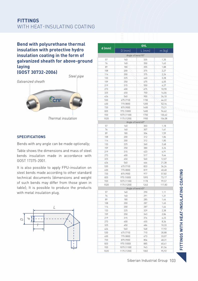
103Siberian Industrial Group
Bend with polyurethane thermal insulation with protective hydro insulation coating in the form of galvanized sheath for above-ground laying (GOST 30732-2006)
SPECIFICATIONS
Bends with any angle can be made optionally;
Table shows the dimensions and mass of steel bends insulation made in accordance with GOST 17375-2001.
It is also possible to apply FPU-insulation on steel bends made according to other standard technical documents (dimensions and weight of such bends may differ from those given in table); It is possible to produce the products with metal insulation plug.
d (mm)GVL
D (mm) L (mm) m (kg)Angle of bend 90°
57 140 335 1,3576 160 350 1,6389 180 355 1,88
108 200 375 2,27114 200 375 2,26133 225 440 3,28159 250 475 4,05219 315 550 6,27273 400 675 10,90325 450 750 14,06426 560 900 26,10530 675 (710) 1150 44,22630 775 (800) 1200 52,16720 875 (900) 1400 73,21820 975 (1000) 1600 94,62920 1075 (1100) 1750 130,62
1020 1175 (1200) 1900 156,08Angle of bend 60°
57 140 303 1,1876 160 307 1,4189 180 304 1,59
108 200 312 1,86114 200 312 1,85133 225 360 2,68159 250 380 3,26219 315 423 4,91273 400 517 9,64325 450 560 12,07426 560 646 21,38530 675 (710) 833 36,24630 775 (800) 819 40,48720 875 (900) 977 57,82820 975 (1000) 1093 73,17920 1075 (1100) 1178 99,57
1020 1175 (1200) 1263 117,83Angle of bend 45°
57 140 290 1,1176 160 291 1,3189 180 285 1,44
108 200 287 1,65114 200 287 1,64133 225 329 2,38159 250 343 2,86219 315 374 4,23273 400 455 8,36325 450 486 10,33426 560 548 17,92530 675 (710) 710 30,88630 775 (800) 673 33,07720 875 (900) 804 48,31820 975 (1000) 885 60,41920 1075 (1100) 943 81,56
1020 1175 (1200) 1002 95,92
Galvanized sheathSteel pipe
Thermal insulation
L
D d
l
FITT
ING
S W
ITH
HEA
T-IN
SULA
TIN
G C
OAT
ING
FITTINGS WITH HEAT-INSULATING COATING
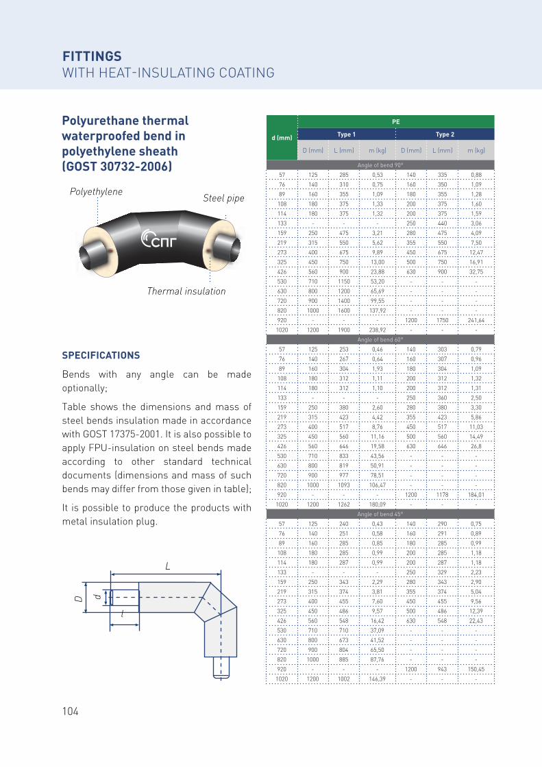
104
Polyurethane thermal waterproofed bend in polyethylene sheath (GOST 30732-2006)
SPECIFICATIONS
Bends with any angle can be made optionally;
Table shows the dimensions and mass of steel bends insulation made in accordance with GOST 17375-2001. It is also possible to apply FPU-insulation on steel bends made according to other standard technical documents (dimensions and mass of such bends may differ from those given in table);
It is possible to produce the products with metal insulation plug.
d (mm)
PE
Type 1 Type 2
D (mm) L (mm) m (kg) D (mm) L (mm) m (kg)
Angle of bend 90°
57 125 285 0,53 140 335 0,88
76 140 310 0,75 160 350 1,09
89 160 355 1,09 180 355 1,28
108 180 375 1,33 200 375 1,60
114 180 375 1,32 200 375 1,59
133 - - - 250 440 3,06
159 250 475 3,21 280 475 4,09
219 315 550 5,62 355 550 7,50
273 400 675 9,89 450 675 12,47
325 450 750 13,00 500 750 16,91
426 560 900 23,88 630 900 32,75
530 710 1150 53,20 - - -
630 800 1200 65,69 - - -
720 900 1400 99,55 - - -
820 1000 1600 137,92 - - -
920 - - - 1200 1750 241,64
1020 1200 1900 238,92 - - -
Angle of bend 60°
57 125 253 0,46 140 303 0,79
76 140 267 0,64 160 307 0,96
89 160 304 1,93 180 304 1,09
108 180 312 1,11 200 312 1,32
114 180 312 1,10 200 312 1,31
133 - - - 250 360 2,50
159 250 380 2,60 280 380 3,30
219 315 423 4,42 355 423 5,86
273 400 517 8,76 450 517 11,03
325 450 560 11,16 500 560 14,49
426 560 646 19,58 630 646 26,8
530 710 833 43,56 - - -
630 800 819 50,91 - - -
720 900 977 78,51 - - -
820 1000 1093 106,47 - - -
920 - - - 1200 1178 184,01
1020 1200 1262 180,09 - - -
Angle of bend 45°
57 125 240 0,43 140 290 0,75
76 140 251 0,58 160 291 0,89
89 160 285 0,85 180 285 0,99
108 180 285 0,99 200 285 1,18
114 180 287 0,99 200 287 1,18
133 - - - 250 329 2,23
159 250 343 2,29 280 343 2,90
219 315 374 3,81 355 374 5,04
273 400 455 7,60 450 455 9,56
325 450 486 9,57 500 486 12,39
426 560 548 16,42 630 548 22,43
530 710 710 37,09 - - -
630 800 673 41,52 - - -
720 900 804 65,50 - - -
820 1000 885 87,76 - - -
920 - - - 1200 943 150,45
1020 1200 1002 146,39 - - -
Polyethylene Steel pipe
Thermal insulation
L
D d
l
FITTINGS WITH HEAT-INSULATING COATING
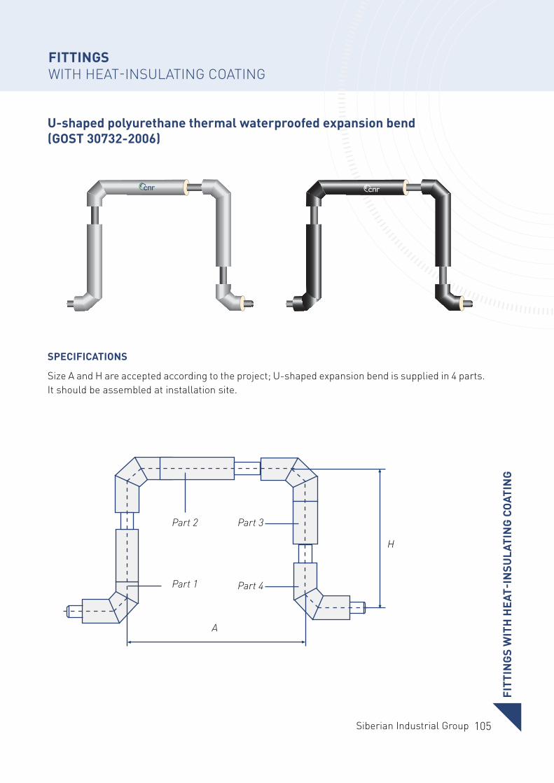
105Siberian Industrial Group
U-shaped polyurethane thermal waterproofed expansion bend (GOST 30732-2006)
SPECIFICATIONS
Size A and H are accepted according to the project; U-shaped expansion bend is supplied in 4 parts.It should be assembled at installation site.
А
Н
Part 1
Part 2 Part 3
Part 4
FITT
ING
S W
ITH
HEA
T-IN
SULA
TIN
G C
OAT
ING
FITTINGS WITH HEAT-INSULATING COATING
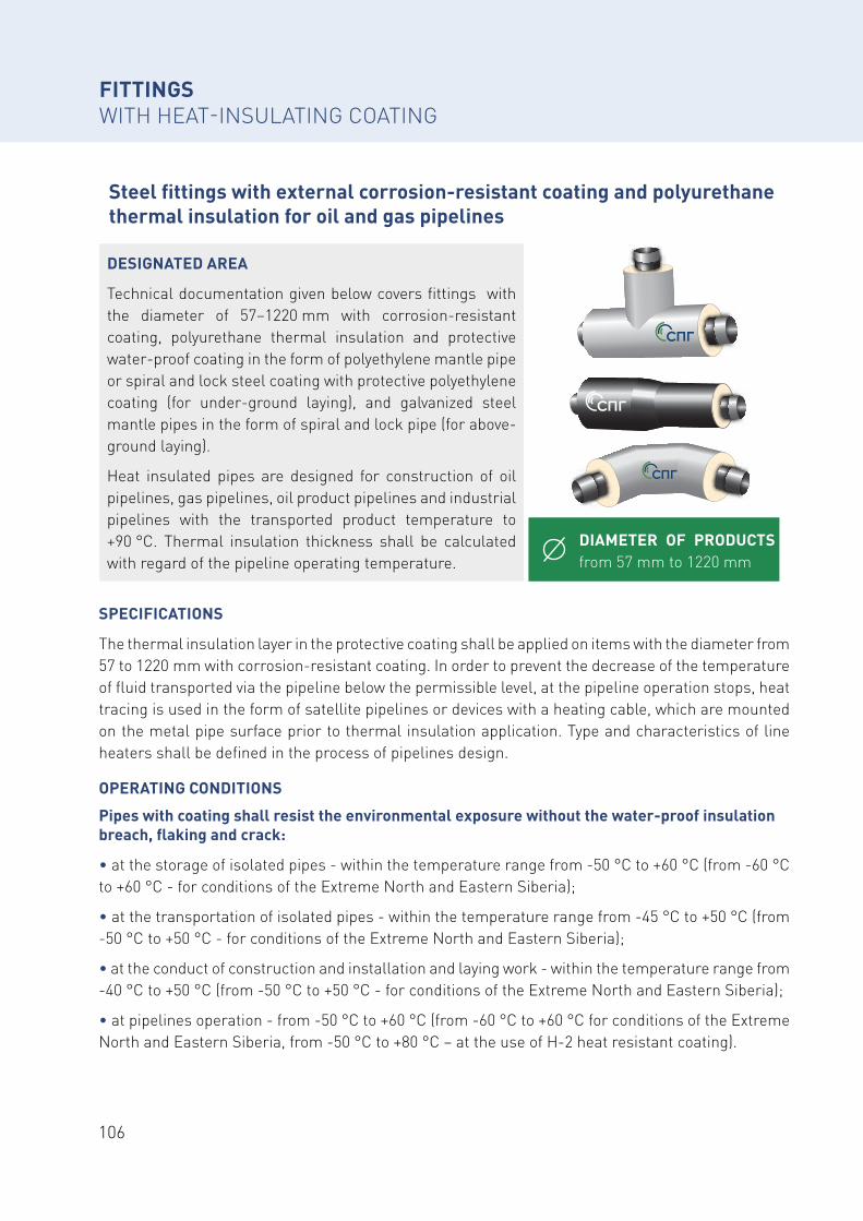
106
Steel fittings with external corrosion-resistant coating and polyurethane thermal insulation for oil and gas pipelines
DIAMETER OF PRODUCTS from 57 mm to 1220 mm
DESIGNATED AREA
Technical documentation given below covers fittings with the diameter of 57–1220 mm with corrosion-resistant coating, polyurethane thermal insulation and protective water-proof coating in the form of polyethylene mantle pipe or spiral and lock steel coating with protective polyethylene coating (for under-ground laying), and galvanized steel mantle pipes in the form of spiral and lock pipe (for above-ground laying).
Heat insulated pipes are designed for construction of oil pipelines, gas pipelines, oil product pipelines and industrial pipelines with the transported product temperature to +90 °C. Thermal insulation thickness shall be calculated with regard of the pipeline operating temperature.
SPECIFICATIONS
The thermal insulation layer in the protective coating shall be applied on items with the diameter from 57 to 1220 mm with corrosion-resistant coating. In order to prevent the decrease of the temperature of fluid transported via the pipeline below the permissible level, at the pipeline operation stops, heat tracing is used in the form of satellite pipelines or devices with a heating cable, which are mounted on the metal pipe surface prior to thermal insulation application. Type and characteristics of line heaters shall be defined in the process of pipelines design.
OPERATING CONDITIONS
Pipes with coating shall resist the environmental exposure without the water-proof insulation breach, flaking and crack:
• at the storage of isolated pipes - within the temperature range from -50 °C to +60 °C (from -60 °C to +60 °C - for conditions of the Extreme North and Eastern Siberia);
• at the transportation of isolated pipes - within the temperature range from -45 °C to +50 °C (from -50 °C to +50 °C - for conditions of the Extreme North and Eastern Siberia);
• at the conduct of construction and installation and laying work - within the temperature range from -40 °C to +50 °C (from -50 °C to +50 °C - for conditions of the Extreme North and Eastern Siberia);
• at pipelines operation - from -50 °C to +60 °C (from -60 °C to +60 °C for conditions of the Extreme North and Eastern Siberia, from -50 °C to +80 °C – at the use of H-2 heat resistant coating).
FITTINGS WITH HEAT-INSULATING COATING
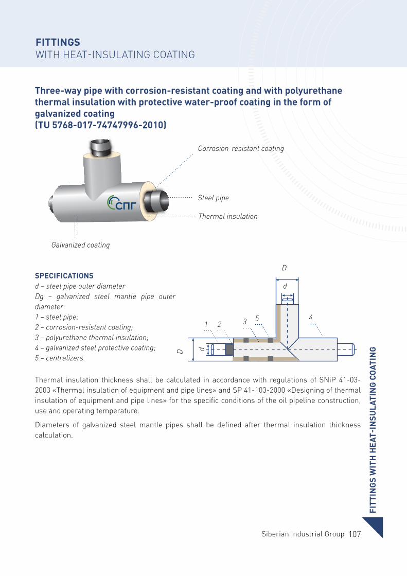
107Siberian Industrial Group
Three-way pipe with corrosion-resistant coating and with polyurethane thermal insulation with protective water-proof coating in the form of galvanized coating (TU 5768-017-74747996-2010)
Galvanized coating
Thermal insulation
Corrosion-resistant coating
Steel pipe
SPECIFICATIONSd – steel pipe outer diameterDg – galvanized steel mantle pipe outer diameter1 – steel pipe;2 – corrosion-resistant coating;3 – polyurethane thermal insulation;4 – galvanized steel protective coating;5 – centralizers.
Thermal insulation thickness shall be calculated in accordance with regulations of SNiP 41-03-2003 «Thermal insulation of equipment and pipe lines» and SP 41-103-2000 «Designing of thermal insulation of equipment and pipe lines» for the specific conditions of the oil pipeline construction, use and operating temperature.
Diameters of galvanized steel mantle pipes shall be defined after thermal insulation thickness calculation.
D
D
d
d
1 25 43
FITT
ING
S W
ITH
HEA
T-IN
SULA
TIN
G C
OAT
ING
FITTINGS WITH HEAT-INSULATING COATING
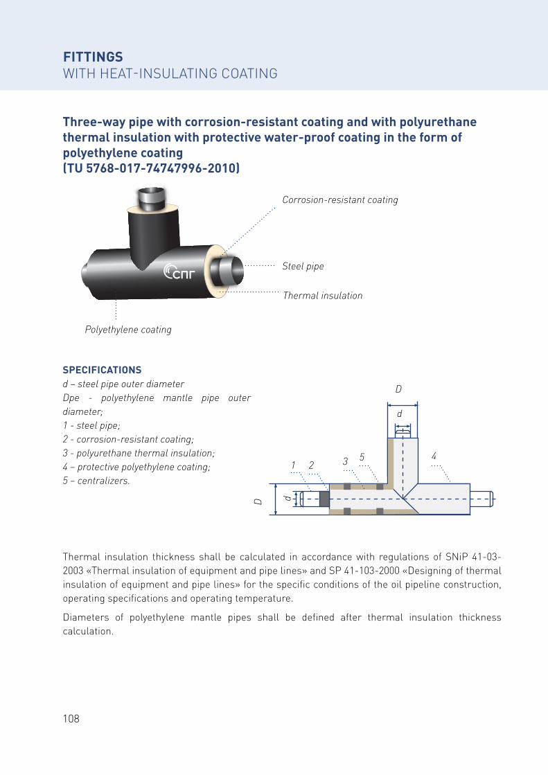
108
Three-way pipe with corrosion-resistant coating and with polyurethane thermal insulation with protective water-proof coating in the form of polyethylene coating (TU 5768-017-74747996-2010)
Polyethylene coating
Thermal insulation
Corrosion-resistant coating
Steel pipe
SPECIFICATIONSd – steel pipe outer diameter Dpe - polyethylene mantle pipe outer diameter; 1 - steel pipe;2 - corrosion-resistant coating;3 - polyurethane thermal insulation; 4 – protective polyethylene coating;5 – centralizers.
Thermal insulation thickness shall be calculated in accordance with regulations of SNiP 41-03-2003 «Thermal insulation of equipment and pipe lines» and SP 41-103-2000 «Designing of thermal insulation of equipment and pipe lines» for the specific conditions of the oil pipeline construction, operating specifications and operating temperature.
Diameters of polyethylene mantle pipes shall be defined after thermal insulation thickness calculation.
D
D
d
d
1 25 43
FITTINGS WITH HEAT-INSULATING COATING
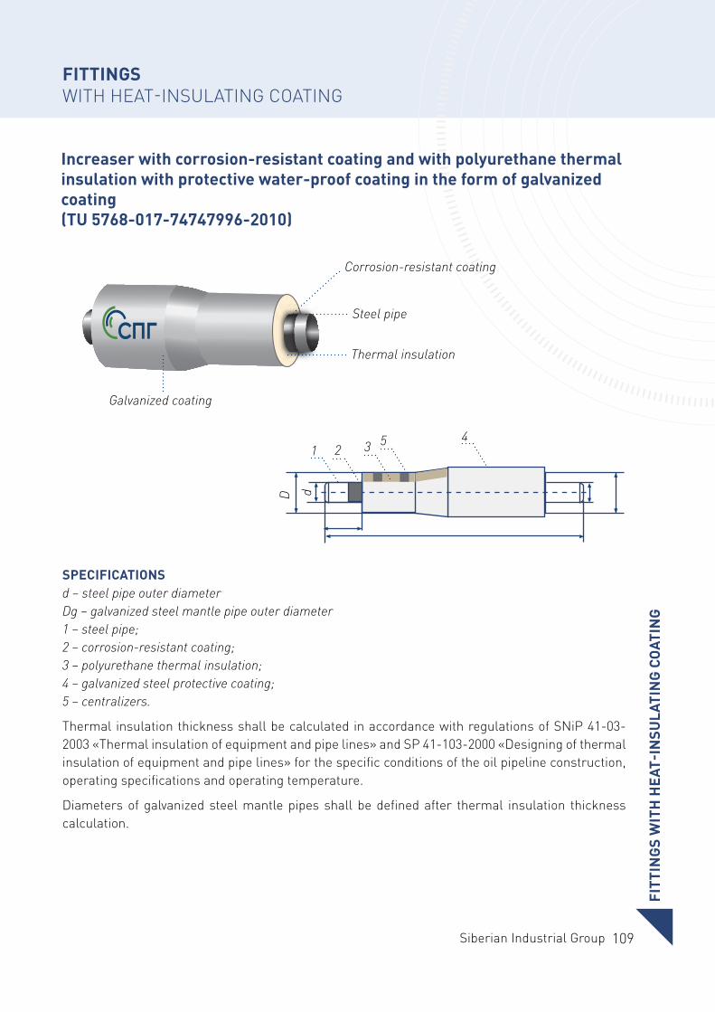
109Siberian Industrial Group
Increaser with corrosion-resistant coating and with polyurethane thermal insulation with protective water-proof coating in the form of galvanized coating (TU 5768-017-74747996-2010)
Galvanized coating
Thermal insulation
Corrosion-resistant coating
Steel pipe
SPECIFICATIONSd – steel pipe outer diameterDg – galvanized steel mantle pipe outer diameter 1 – steel pipe;2 – corrosion-resistant coating;3 – polyurethane thermal insulation;4 – galvanized steel protective coating; 5 – centralizers.
Thermal insulation thickness shall be calculated in accordance with regulations of SNiP 41-03-2003 «Thermal insulation of equipment and pipe lines» and SP 41-103-2000 «Designing of thermal insulation of equipment and pipe lines» for the specific conditions of the oil pipeline construction, operating specifications and operating temperature.
Diameters of galvanized steel mantle pipes shall be defined after thermal insulation thickness calculation.
D d
1 2 3 5 4
FITT
ING
S W
ITH
HEA
T-IN
SULA
TIN
G C
OAT
ING
FITTINGS WITH HEAT-INSULATING COATING
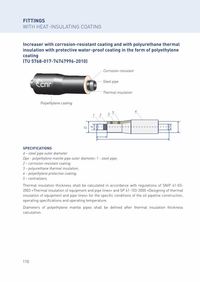
110
Increaser with corrosion-resistant coating and with polyurethane thermal insulation with protective water-proof coating in the form of polyethylene coating (TU 5768-017-74747996-2010)
SPECIFICATIONSd – steel pipe outer diameterDpe - polyethylene mantle pipe outer diameter; 1 - steel pipe;2 – corrosion-resistant coating;3 – polyurethane thermal insulation; 4 – polyethylene protective coating; 5 – centralizers.
Thermal insulation thickness shall be calculated in accordance with regulations of SNiP 41-03-2003 «Thermal insulation of equipment and pipe lines» and SP 41-103-2000 «Designing of thermal insulation of equipment and pipe lines» for the specific conditions of the oil pipeline construction, operating specifications and operating temperature.
Diameters of polyethylene mantle pipes shall be defined after thermal insulation thickness calculation.
Polyethylene coating
Thermal insulation
Corrosion-resistant
Steel pipeD d
1 2 3 5 4
FITTINGS WITH HEAT-INSULATING COATING
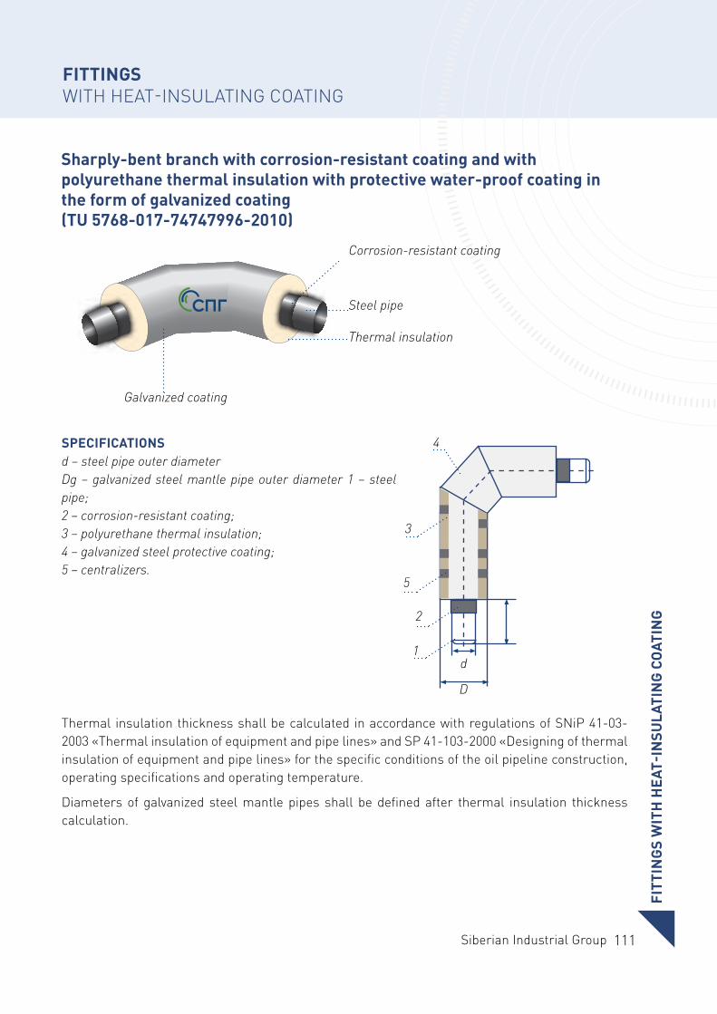
111Siberian Industrial Group
Sharply-bent branch with corrosion-resistant coating and with polyurethane thermal insulation with protective water-proof coating in the form of galvanized coating (TU 5768-017-74747996-2010)
Galvanized coating
Thermal insulation
Corrosion-resistant coating
Steel pipe
SPECIFICATIONSd – steel pipe outer diameterDg – galvanized steel mantle pipe outer diameter 1 – steel pipe; 2 – corrosion-resistant coating; 3 – polyurethane thermal insulation; 4 – galvanized steel protective coating; 5 – centralizers.
Thermal insulation thickness shall be calculated in accordance with regulations of SNiP 41-03-2003 «Thermal insulation of equipment and pipe lines» and SP 41-103-2000 «Designing of thermal insulation of equipment and pipe lines» for the specific conditions of the oil pipeline construction, operating specifications and operating temperature.
Diameters of galvanized steel mantle pipes shall be defined after thermal insulation thickness calculation.
D
d1
2
4
5
3
FITT
ING
S W
ITH
HEA
T-IN
SULA
TIN
G C
OAT
ING
FITTINGS WITH HEAT-INSULATING COATING
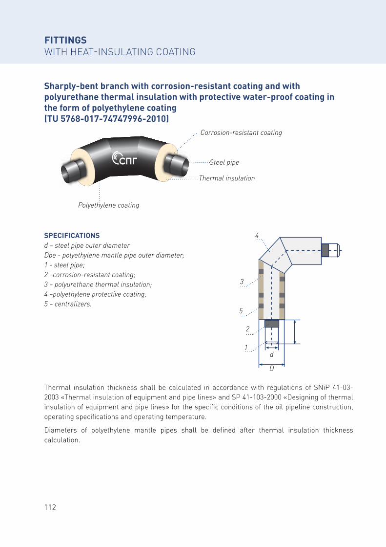
112
Sharply-bent branch with corrosion-resistant coating and with polyurethane thermal insulation with protective water-proof coating in the form of polyethylene coating (TU 5768-017-74747996-2010)
Thermal insulation thickness shall be calculated in accordance with regulations of SNiP 41-03-2003 «Thermal insulation of equipment and pipe lines» and SP 41-103-2000 «Designing of thermal insulation of equipment and pipe lines» for the specific conditions of the oil pipeline construction, operating specifications and operating temperature.
Diameters of polyethylene mantle pipes shall be defined after thermal insulation thickness calculation.
SPECIFICATIONSd – steel pipe outer diameterDpe - polyethylene mantle pipe outer diameter; 1 - steel pipe;2 –corrosion-resistant coating;3 – polyurethane thermal insulation; 4 –polyethylene protective coating; 5 – centralizers.
Polyethylene coating
Thermal insulation
Corrosion-resistant coating
Steel pipe
D
d1
2
4
5
3
FITTINGS WITH HEAT-INSULATING COATING
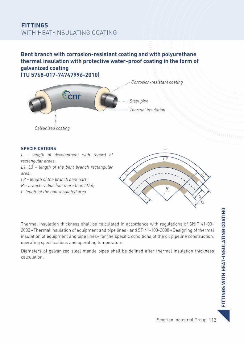
113Siberian Industrial Group
Bent branch with corrosion-resistant coating and with polyurethane thermal insulation with protective water-proof coating in the form of galvanized coating (TU 5768-017-74747996-2010)
Thermal insulation thickness shall be calculated in accordance with regulations of SNiP 41-03-2003 «Thermal insulation of equipment and pipe lines» and SP 41-103-2000 «Designing of thermal insulation of equipment and pipe lines» for the specific conditions of the oil pipeline construction, operating specifications and operating temperature.
Diameters of galvanized steel mantle pipes shall be defined after thermal insulation thickness calculation.
SPECIFICATIONSL – length of development with regard of rectangular areas; L1, L3 – length of the bent branch rectangular area;L2 – length of the branch bent part;R – branch radius (not more than 5Du);l– length of the non-insulated area
Galvanized coating
Thermal insulation
Corrosion-resistant coating
Steel pipe
L
L2
R
L1 L3
Ddl
FITT
ING
S W
ITH
HEA
T-IN
SULA
TIN
G C
OAT
ING
FITTINGS WITH HEAT-INSULATING COATING
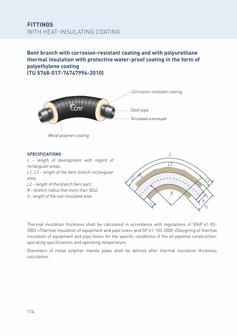
114
Bent branch with corrosion-resistant coating and with polyurethane thermal insulation with protective water-proof coating in the form of polyethylene coating (TU 5768-017-74747996-2010)
Thermal insulation thickness shall be calculated in accordance with regulations of SNiP 41-03-2003 «Thermal insulation of equipment and pipe lines» and SP 41-103-2000 «Designing of thermal insulation of equipment and pipe lines» for the specific conditions of the oil pipeline construction, operating specifications and operating temperature.
Diameters of metal polymer mantle pipes shall be defined after thermal insulation thickness calculation.
SPECIFICATIONSL – length of development with regard of rectangular areas; L1, L3 – length of the bent branch rectangular area; L2 – length of the branch bent part;R – branch radius (not more than 5Du);ll– length of the non-insulated area
L
L2
R
L1 L3
Ddl
Metal polymer coating
Тепловая изоляция
Corrosion-resistant coating
Steel pipe
FITTINGS WITH HEAT-INSULATING COATING
115Siberian Industrial Group
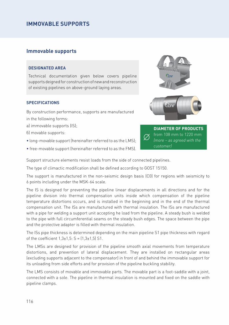
116
Immovable supports
IMMOVABLE SUPPORTS
DIAMETER OF PRODUCTS from 108 mm to 1220 mm (more – as agreed with the customer)
DESIGNATED AREA
Technical documentation given below covers pipeline supports deigned for construction of new and reconstruction of existing pipelines on above-ground laying areas.
Support structure elements resist loads from the side of connected pipelines.
The type of climactic modification shall be defined according to GOST 15150.
The support is manufactured in the non-seismic design basis (С0) for regions with seismicity to 6 points including under the MSK-64 scale.
The IS is designed for preventing the pipeline linear displacements in all directions and for the pipeline division into thermal compensation units inside which compensation of the pipeline temperature distortions occurs, and is installed in the beginning and in the end of the thermal compensation unit. The ISs are manufactured with thermal insulation. The ISs are manufactured with a pipe for welding a support unit accepting he load from the pipeline. A steady bush is welded to the pipe with full circumferential seams on the steady bush edges. The space between the pipe and the protective adapter is filled with thermal insulation.
The ISs pipe thickness is determined depending on the main pipeline S1 pipe thickness with regard of the coefficient 1,3±1,5: S = (1,3±1,5) S1.
The LMSs are designed for provision of the pipeline smooth axial movements from temperature distortions, and prevention of lateral displacement. They are installed on rectangular areas (excluding supports adjacent to the compensator) in front of and behind the immovable support for its unloading from side efforts and for provision of the pipeline buckling stability.
The LMS consists of movable and immovable parts. The movable part is a foot-saddle with a joint, connected with a sole. The pipeline in thermal insulation is mounted and fixed on the saddle with pipeline clamps.
SPECIFICATIONS
By construction performance, supports are manufactured
in the following forms:
а) immovable supports (IS);
б) movable supports:
• long-movable support (hereinafter referred to as the LMS);
• free-movable support (hereinafter referred to as the FMS).
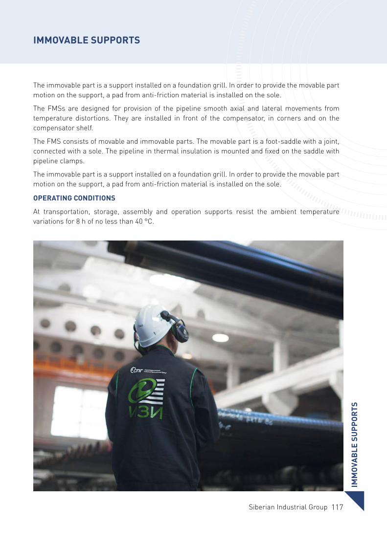
117Siberian Industrial Group
IMM
OVA
BLE
SU
PPO
RTS
IMMOVABLE SUPPORTS
The immovable part is a support installed on a foundation grill. In order to provide the movable part motion on the support, a pad from anti-friction material is installed on the sole.
The FMSs are designed for provision of the pipeline smooth axial and lateral movements from temperature distortions. They are installed in front of the compensator, in corners and on the compensator shelf.
The FMS consists of movable and immovable parts. The movable part is a foot-saddle with a joint, connected with a sole. The pipeline in thermal insulation is mounted and fixed on the saddle with pipeline clamps.
The immovable part is a support installed on a foundation grill. In order to provide the movable part motion on the support, a pad from anti-friction material is installed on the sole.
OPERATING CONDITIONS
At transportation, storage, assembly and operation supports resist the ambient temperature variations for 8 h of no less than 40 °С.
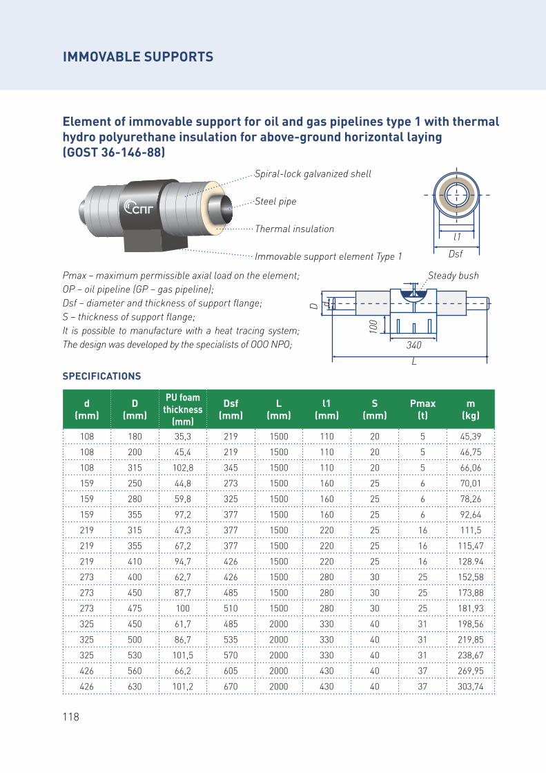
118
Element of immovable support for oil and gas pipelines type 1 with thermal hydro polyurethane insulation for above-ground horizontal laying (GOST 36-146-88)
Рmах – maximum permissible axial load on the element;OP – oil pipeline (GP – gas pipeline);Dsf – diameter and thickness of support flange; S – thickness of support flange;It is possible to manufacture with a heat tracing system; The design was developed by the specialists of OOO NPO;
L
D
100
340
Steady bush
d
Spiral-lock galvanized shell
Steel pipe
Thermal insulation
Immovable support element Type 1
l1Dsf
d (mm)
D (mm)
PU foam thickness
(mm)
Dsf (mm)
L (mm)
l1 (mm)
S (mm)
Pmax (t)
m (kg)
108 180 35,3 219 1500 110 20 5 45,39
108 200 45,4 219 1500 110 20 5 46,75
108 315 102,8 345 1500 110 20 5 66,06
159 250 44,8 273 1500 160 25 6 70,01
159 280 59,8 325 1500 160 25 6 78,26
159 355 97,2 377 1500 160 25 6 92,64
219 315 47,3 377 1500 220 25 16 111,5
219 355 67,2 377 1500 220 25 16 115,47
219 410 94,7 426 1500 220 25 16 128.94
273 400 62,7 426 1500 280 30 25 152,58
273 450 87,7 485 1500 280 30 25 173,88
273 475 100 510 1500 280 30 25 181,93
325 450 61,7 485 2000 330 40 31 198,56
325 500 86,7 535 2000 330 40 31 219,85
325 530 101,5 570 2000 330 40 31 238,67
426 560 66,2 605 2000 430 40 37 269,95
426 630 101,2 670 2000 430 40 37 303,74
IMMOVABLE SUPPORTS
SPECIFICATIONS
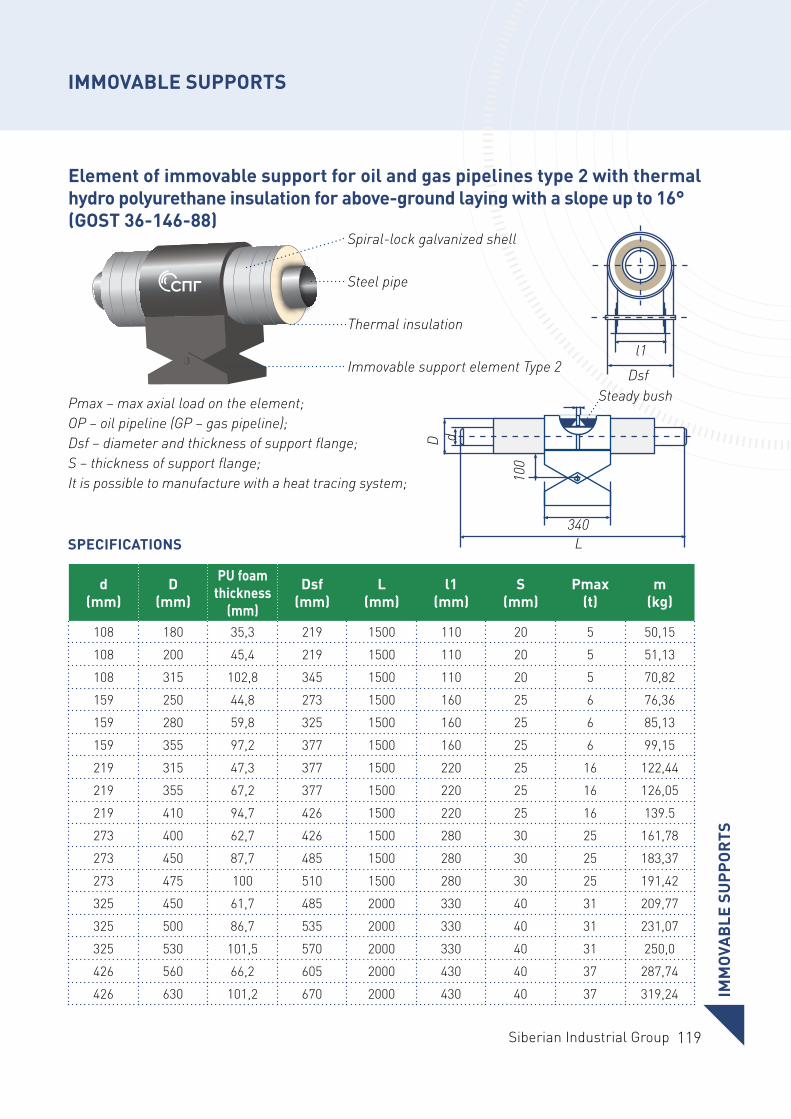
119Siberian Industrial Group
Element of immovable support for oil and gas pipelines type 2 with thermal hydro polyurethane insulation for above-ground laying with a slope up to 16° (GOST 36-146-88)
d (mm)
D (mm)
PU foam thickness
(mm)
Dsf (mm)
L (mm)
l1 (mm)
S (mm)
Pmax (t)
m (kg)
108 180 35,3 219 1500 110 20 5 50,15
108 200 45,4 219 1500 110 20 5 51,13
108 315 102,8 345 1500 110 20 5 70,82
159 250 44,8 273 1500 160 25 6 76,36
159 280 59,8 325 1500 160 25 6 85,13
159 355 97,2 377 1500 160 25 6 99,15
219 315 47,3 377 1500 220 25 16 122,44
219 355 67,2 377 1500 220 25 16 126,05
219 410 94,7 426 1500 220 25 16 139.5
273 400 62,7 426 1500 280 30 25 161,78
273 450 87,7 485 1500 280 30 25 183,37
273 475 100 510 1500 280 30 25 191,42
325 450 61,7 485 2000 330 40 31 209,77
325 500 86,7 535 2000 330 40 31 231,07
325 530 101,5 570 2000 330 40 31 250,0
426 560 66,2 605 2000 430 40 37 287,74
426 630 101,2 670 2000 430 40 37 319,24
Рmах – max axial load on the element;OP – oil pipeline (GP – gas pipeline);Dsf – diameter and thickness of support flange; S – thickness of support flange;It is possible to manufacture with a heat tracing system;
L
D
100
340
Steady bush
d
Spiral-lock galvanized shell
Steel pipe
Thermal insulation
Immovable support element Type 2l1
Dsf
IMM
OVA
BLE
SU
PPO
RTS
IMMOVABLE SUPPORTS
SPECIFICATIONS
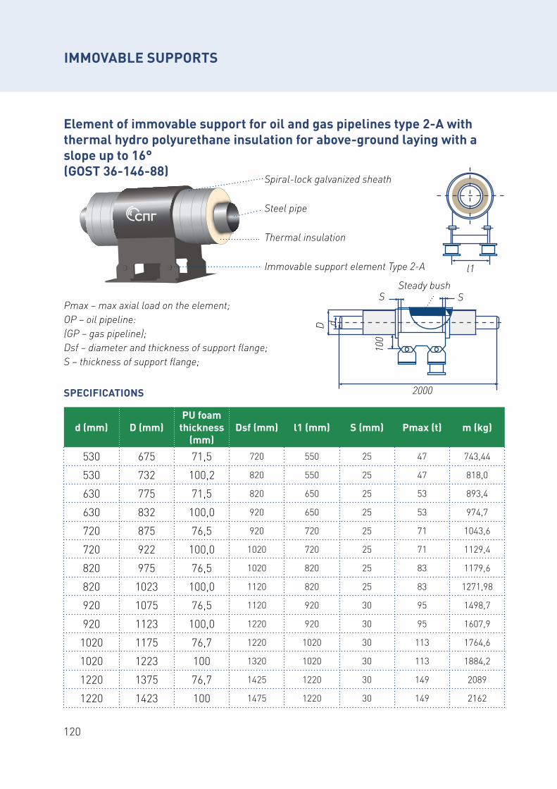
120
Element of immovable support for oil and gas pipelines type 2-A with thermal hydro polyurethane insulation for above-ground laying with a slope up to 16° (GOST 36-146-88) Spiral-lock galvanized sheath
Steel pipe
Thermal insulation
Immovable support element Type 2-А
Рmах – max axial load on the element;OP – oil pipeline:(GP – gas pipeline);Dsf – diameter and thickness of support flange; S – thickness of support flange;
SPECIFICATIONS
d (mm) D (mm)PU foam
thickness (mm)
Dsf (mm) l1 (mm) S (mm) Pmax (t) m (kg)
530 675 71,5 720 550 25 47 743,44
530 732 100,2 820 550 25 47 818,0
630 775 71,5 820 650 25 53 893,4
630 832 100,0 920 650 25 53 974,7
720 875 76,5 920 720 25 71 1043,6
720 922 100,0 1020 720 25 71 1129,4
820 975 76,5 1020 820 25 83 1179,6
820 1023 100,0 1120 820 25 83 1271,98
920 1075 76,5 1120 920 30 95 1498,7
920 1123 100,0 1220 920 30 95 1607,9
1020 1175 76,7 1220 1020 30 113 1764,6
1020 1223 100 1320 1020 30 113 1884,2
1220 1375 76,7 1425 1220 30 149 2089
1220 1423 100 1475 1220 30 149 2162
Steady bush
2000
S S
D
100
d
l1
IMMOVABLE SUPPORTS
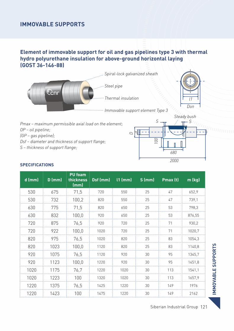
121Siberian Industrial Group
Element of immovable support for oil and gas pipelines type 3 with thermal hydro polyurethane insulation for above-ground horizontal laying (GOST 36-146-88)
Spiral-lock galvanized sheath
Steel pipe
Thermal insulation
Immovable support element Type 3
Pmах – maximum permissible axial load on the element;OP – oil pipeline;(GP – gas pipeline);Dsf – diameter and thickness of support flange;S – thickness of support flange;
SPECIFICATIONS
d (mm) D (mm)PU foam
thickness (mm)
Dsf (mm) l1 (mm) S (mm) Pmax (t) m (kg)
530 675 71,5 720 550 25 47 652,9
530 732 100,2 820 550 25 47 739,1
630 775 71,5 820 650 25 53 798,3
630 832 100,0 920 650 25 53 876,55
720 875 76,5 920 720 25 71 930,2
720 922 100,0 1020 720 25 71 1020,7
820 975 76,5 1020 820 25 83 1054,3
820 1023 100,0 1120 820 25 83 1140,8
920 1075 76,5 1120 920 30 95 1345,7
920 1123 100,0 1220 920 30 95 1451,8
1020 1175 76,7 1220 1020 30 113 1541,1
1020 1223 100 1320 1020 30 113 1657,9
1220 1375 76,5 1425 1220 30 149 1976
1220 1423 100 1475 1220 30 149 2162
2000
S S
D
100
d
680
Steady bush
l1Dоп
IMM
OVA
BLE
SU
PPO
RTS
IMMOVABLE SUPPORTS
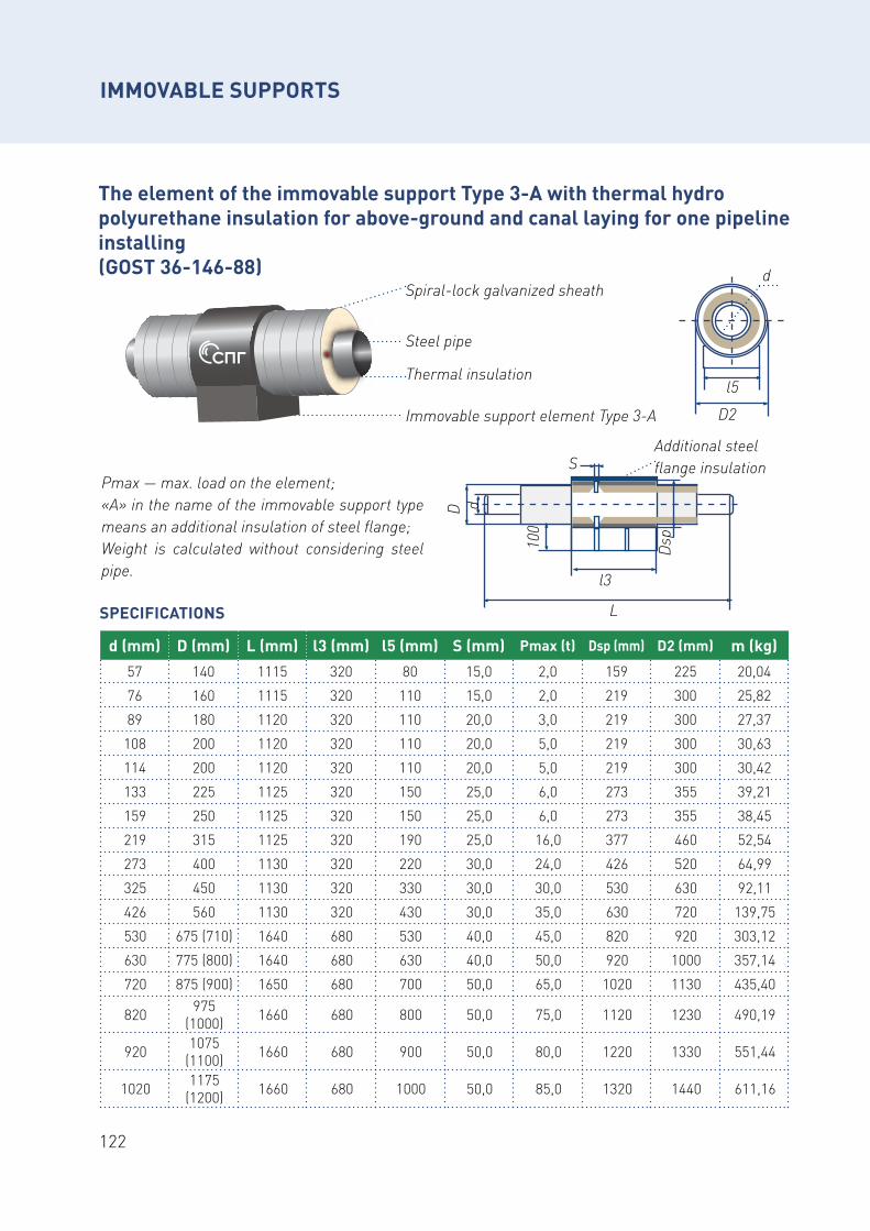
122
The element of the immovable support Type 3-A with thermal hydro polyurethane insulation for above-ground and canal laying for one pipeline installing (GOST 36-146-88)
Рmах — max. load on the element;«А» in the name of the immovable support type means an additional insulation of steel flange;Weight is calculated without considering steel pipe.
SPECIFICATIONS
d (mm) D (mm) L (mm) l3 (mm) l5 (mm) S (mm) Pmax (t) Dsp (mm) D2 (mm) m (kg)57 140 1115 320 80 15,0 2,0 159 225 20,04
76 160 1115 320 110 15,0 2,0 219 300 25,82
89 180 1120 320 110 20,0 3,0 219 300 27,37
108 200 1120 320 110 20,0 5,0 219 300 30,63
114 200 1120 320 110 20,0 5,0 219 300 30,42
133 225 1125 320 150 25,0 6,0 273 355 39,21
159 250 1125 320 150 25,0 6,0 273 355 38,45
219 315 1125 320 190 25,0 16,0 377 460 52,54
273 400 1130 320 220 30,0 24,0 426 520 64,99
325 450 1130 320 330 30,0 30,0 530 630 92,11
426 560 1130 320 430 30,0 35,0 630 720 139,75
530 675 (710) 1640 680 530 40,0 45,0 820 920 303,12
630 775 (800) 1640 680 630 40,0 50,0 920 1000 357,14
720 875 (900) 1650 680 700 50,0 65,0 1020 1130 435,40
820 975 (1000) 1660 680 800 50,0 75,0 1120 1230 490,19
920 1075 (1100) 1660 680 900 50,0 80,0 1220 1330 551,44
1020 1175 (1200) 1660 680 1000 50,0 85,0 1320 1440 611,16
Immovable support element Type 3-А
Thermal insulation
Spiral-lock galvanized sheath
Steel pipe
l5D2
d
L
SD
100
d
l3
Dsp
Additional steel flange insulation
IMMOVABLE SUPPORTS
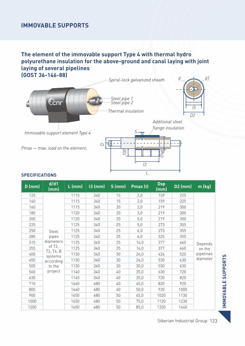
123Siberian Industrial Group
The element of the immovable support Type 4 with thermal hydro polyurethane insulation for the above-ground and canal laying with joint laying of several pipelines (GOST 36-146-88)
Pmах — max. load on the element;
SPECIFICATIONS
Immovable support element Type 4
Thermal insulation
Spiral-lock galvanized sheath
Steel pipe 1Steel pipe 2
D (mm) d/d1 (mm) L (mm) l3 (mm) S (mm) Pmax (t) Dsp
(mm) D2 (mm) m (kg)
125
Steel pipes
diameters of T2,
Т3, Т4, В systems
according to the
project
1115 340 15 2,0 159 225
Depends on the
pipelines diameter
140 1115 340 15 2,0 159 225160 1115 340 20 2,0 219 300180 1120 340 20 3,0 219 300200 1120 340 20 5,0 219 300225 1125 340 25 5,0 273 355250 1125 340 25 6,0 273 355280 1125 340 25 6,0 325 355315 1125 340 25 16,0 377 460355 1125 340 25 16,0 377 460400 1130 340 30 24,0 426 520450 1130 340 30 24,0 530 630500 1130 340 30 30,0 530 630560 1140 340 40 35,0 630 720630 1140 340 40 35,0 720 820710 1640 680 40 45,0 820 920800 1640 680 40 50,0 920 1000900 1650 680 50 65,0 1020 1130
1000 1650 680 50 75,0 1120 12301200 1650 680 50 85,0 1320 1440
L
S
D
100
d
l3Ds
p
Additional steel flange insulation
l5D2
d1d
IMM
OVA
BLE
SU
PPO
RTS
IMMOVABLE SUPPORTS
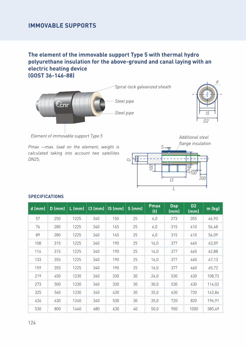
124
The element of the immovable support Type 5 with thermal hydro polyurethane insulation for the above-ground and canal laying with an electric heating device (GOST 36-146-88)
Рmах —max. load on the element; weight is calculated taking into account two satellites DN25;
SPECIFICATIONS
Element of immovable support Тype 5
Steel pipe
Spiral-lock galvanized sheath
Steel pipe
d (mm) D (mm) L (mm) l3 (mm) l5 (mm) S (mm) Pmax (t)
Dsp (mm)
D2 (mm) m (kg)
57 250 1225 340 150 25 6,0 273 355 46,93
76 280 1225 340 165 25 6,0 315 410 56,48
89 280 1225 340 165 25 6,0 315 410 56,09
108 315 1225 340 190 25 16,0 377 460 63,09
114 315 1225 340 190 25 16,0 377 460 62,88
133 355 1225 340 190 25 16,0 377 460 67,13
159 355 1225 340 190 25 16,0 377 460 65,72
219 450 1230 340 330 30 24,0 530 630 108,73
273 500 1230 340 330 30 30,0 530 630 114,02
325 560 1230 340 430 30 35,0 630 720 143,84
426 630 1240 340 530 30 35,0 720 820 196,91
530 800 1640 680 630 40 50,0 900 1000 385,49
L
S
D
100
d
l3 200100Ds
p
Additional steel flange insulation
l5D2
d
IMMOVABLE SUPPORTS
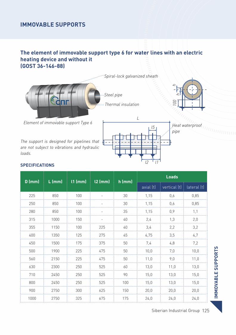
125Siberian Industrial Group
hh
100
The element of immovable support type 6 for water lines with an electric heating device and without it (GOST 36-146-88)
Element of immovable support Тype 6
The support is designed for pipelines that are not subject to vibrations and hydraulic loads.
SPECIFICATIONS
Thermal insulation
Spiral-lock galvanized sheath
Steel pipe
L
l5
l2 l1
Heat waterproof pipe
D (mm) L (mm) l1 (mm) l2 (mm) h (mm)Loads
axial (t) vertical (t) lateral (t)
225 850 100 - 30 1,15 0,6 0,85
250 850 100 - 30 1,15 0,6 0,85
280 850 100 - 35 1,15 0,9 1,1
315 1000 150 - 40 2,4 1,3 2,0
355 1150 100 225 40 3,4 2,2 3,2
400 1350 125 275 45 4,75 3,5 4,7
450 1500 175 375 50 7,4 4,8 7,2
500 1900 225 475 50 10,0 7,0 10,0
560 2150 225 475 50 11,0 9,0 11,0
630 2300 250 525 60 13,0 11,0 13,0
710 2450 250 525 90 15,0 13,0 15,0
800 2450 250 525 100 15,0 13,0 15,0
900 2750 300 625 150 20,0 20,0 20,0
1000 2750 325 675 175 24,0 24,0 24,0 IMM
OVA
BLE
SU
PPO
RTS
IMMOVABLE SUPPORTS
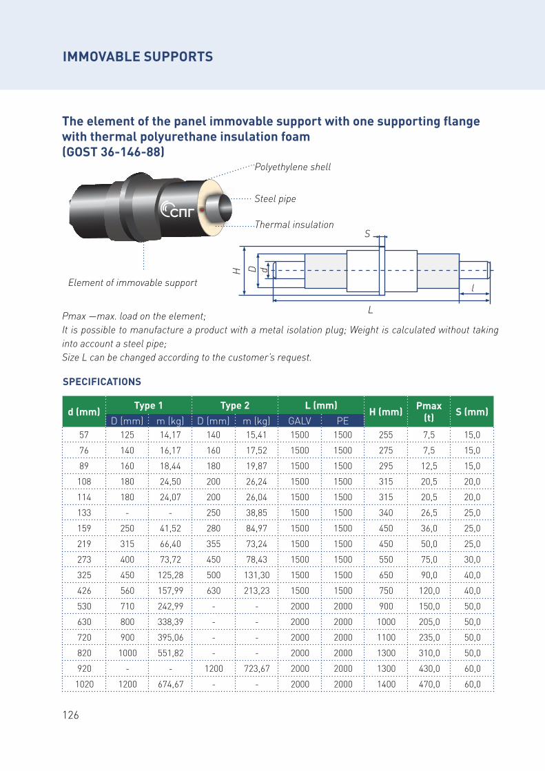
126
The element of the panel immovable support with one supporting flange with thermal polyurethane insulation foam (GOST 36-146-88)
Element of immovable support
Thermal insulation
Polyethylene shell
Steel pipe
Рmах —max. load on the element;It is possible to manufacture a product with a metal isolation plug; Weight is calculated without taking into account a steel pipe;Size L can be changed according to the customer’s request.
SPECIFICATIONS
d (mm)Type 1 Type 2 L (mm)
H (mm) Pmax (t) S (mm)
D (mm) m (kg) D (mm) m (kg) GALV PE57 125 14,17 140 15,41 1500 1500 255 7,5 15,0
76 140 16,17 160 17,52 1500 1500 275 7,5 15,0
89 160 18,44 180 19,87 1500 1500 295 12,5 15,0
108 180 24,50 200 26,24 1500 1500 315 20,5 20,0
114 180 24,07 200 26,04 1500 1500 315 20,5 20,0
133 - - 250 38,85 1500 1500 340 26,5 25,0
159 250 41,52 280 84,97 1500 1500 450 36,0 25,0
219 315 66,40 355 73,24 1500 1500 450 50,0 25,0
273 400 73,72 450 78,43 1500 1500 550 75,0 30,0
325 450 125,28 500 131,30 1500 1500 650 90,0 40,0
426 560 157,99 630 213,23 1500 1500 750 120,0 40,0
530 710 242,99 - - 2000 2000 900 150,0 50,0
630 800 338,39 - - 2000 2000 1000 205,0 50,0
720 900 395,06 - - 2000 2000 1100 235,0 50,0
820 1000 551,82 - - 2000 2000 1300 310,0 50,0
920 - - 1200 723,67 2000 2000 1300 430,0 60,0
1020 1200 674,67 - - 2000 2000 1400 470,0 60,0
L
DH d
l
S
IMMOVABLE SUPPORTS
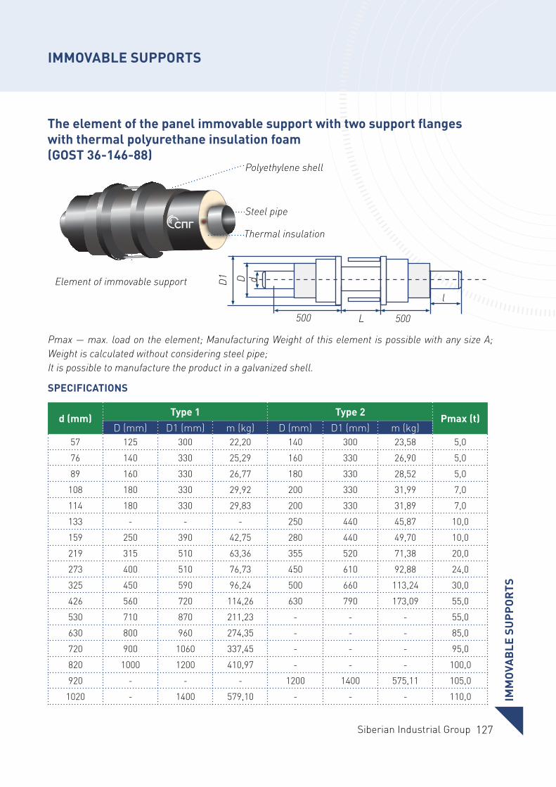
127Siberian Industrial Group
The element of the panel immovable support with two support flanges with thermal polyurethane insulation foam (GOST 36-146-88)
Рmах — max. load on the element; Manufacturing Weight of this element is possible with any size A; Weight is calculated without considering steel pipe;It is possible to manufacture the product in a galvanized shell.
SPECIFICATIONS
Element of immovable support
Thermal insulation
Polyethylene shell
Steel pipe
d (mm)Type 1 Type 2
Pmax (t)D (mm) D1 (mm) m (kg) D (mm) D1 (mm) m (kg)
57 125 300 22,20 140 300 23,58 5,0
76 140 330 25,29 160 330 26,90 5,0
89 160 330 26,77 180 330 28,52 5,0
108 180 330 29,92 200 330 31,99 7,0
114 180 330 29,83 200 330 31,89 7,0
133 - - - 250 440 45,87 10,0
159 250 390 42,75 280 440 49,70 10,0
219 315 510 63,36 355 520 71,38 20,0
273 400 510 76,73 450 610 92,88 24,0
325 450 590 96,24 500 660 113,24 30,0
426 560 720 114,26 630 790 173,09 55,0
530 710 870 211,23 - - - 55,0
630 800 960 274,35 - - - 85,0
720 900 1060 337,45 - - - 95,0
820 1000 1200 410,97 - - - 100,0
920 - - - 1200 1400 575,11 105,0
1020 - 1400 579,10 - - - 110,0
L500 500
DD1 d
l
IMM
OVA
BLE
SU
PPO
RTS
IMMOVABLE SUPPORTS
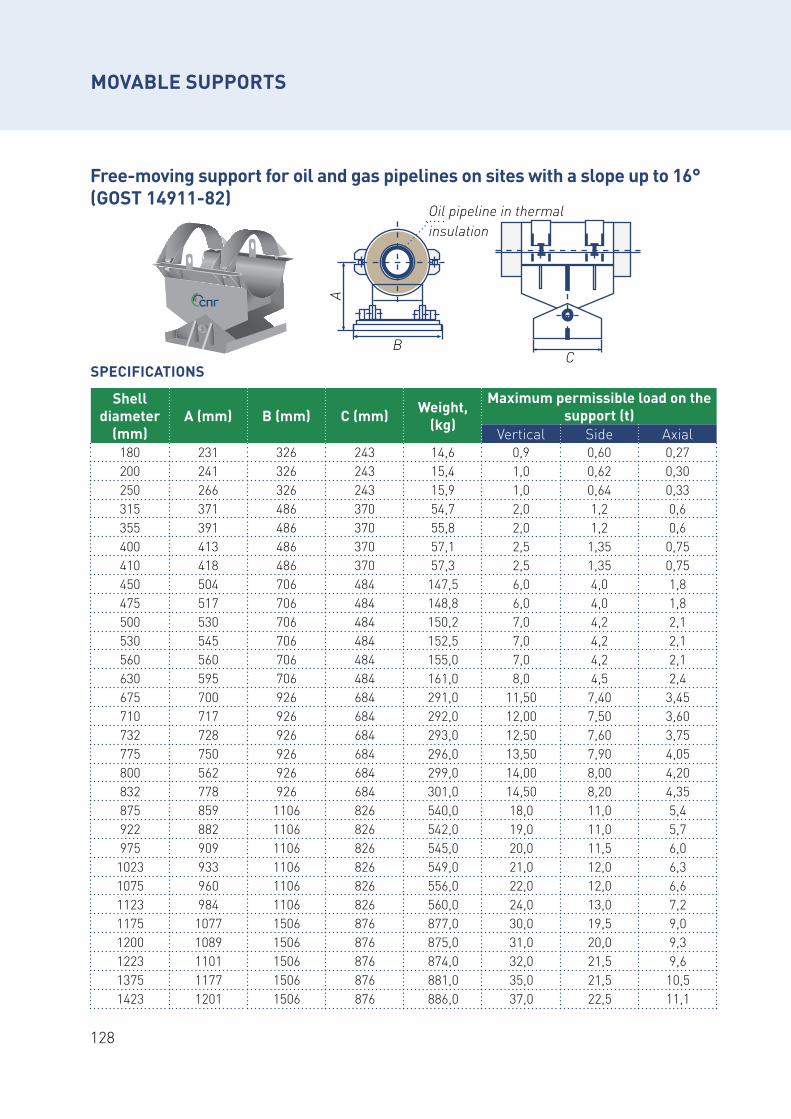
128
Free-moving support for oil and gas pipelines on sites with a slope up to 16° (GOST 14911-82)
MOVABLE SUPPORTS
SPECIFICATIONS
Shell diameter
(mm)А (mm) В (mm) С (mm) Weight,
(kg)
Maximum permissible load on the support (t)
Vertical Side Axial180 231 326 243 14,6 0,9 0,60 0,27200 241 326 243 15,4 1,0 0,62 0,30250 266 326 243 15,9 1,0 0,64 0,33315 371 486 370 54,7 2,0 1,2 0,6355 391 486 370 55,8 2,0 1,2 0,6400 413 486 370 57,1 2,5 1,35 0,75410 418 486 370 57,3 2,5 1,35 0,75450 504 706 484 147,5 6,0 4,0 1,8475 517 706 484 148,8 6,0 4,0 1,8500 530 706 484 150,2 7,0 4,2 2,1530 545 706 484 152,5 7,0 4,2 2,1560 560 706 484 155,0 7,0 4,2 2,1630 595 706 484 161,0 8,0 4,5 2,4675 700 926 684 291,0 11,50 7,40 3,45710 717 926 684 292,0 12,00 7,50 3,60732 728 926 684 293,0 12,50 7,60 3,75775 750 926 684 296,0 13,50 7,90 4,05800 562 926 684 299,0 14,00 8,00 4,20832 778 926 684 301,0 14,50 8,20 4,35875 859 1106 826 540,0 18,0 11,0 5,4922 882 1106 826 542,0 19,0 11,0 5,7975 909 1106 826 545,0 20,0 11,5 6,0
1023 933 1106 826 549,0 21,0 12,0 6,31075 960 1106 826 556,0 22,0 12,0 6,61123 984 1106 826 560,0 24,0 13,0 7,21175 1077 1506 876 877,0 30,0 19,5 9,01200 1089 1506 876 875,0 31,0 20,0 9,31223 1101 1506 876 874,0 32,0 21,5 9,61375 1177 1506 876 881,0 35,0 21,5 10,51423 1201 1506 876 886,0 37,0 22,5 11,1
ВА
Oil pipeline in thermal insulation
С
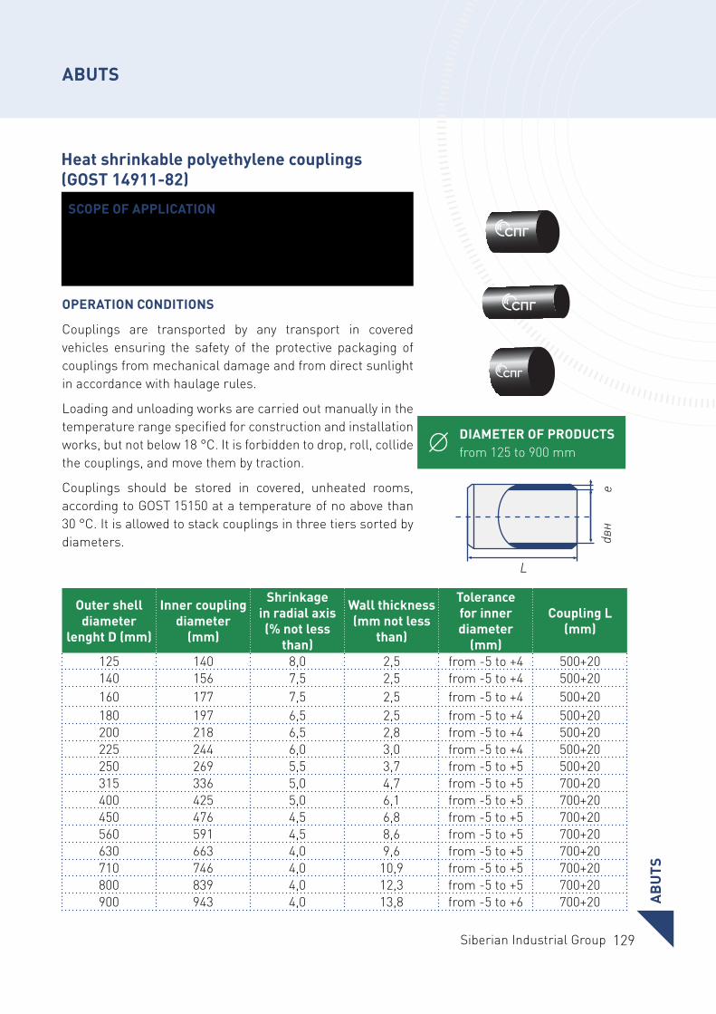
129Siberian Industrial Group
ABUTS
Heat shrinkable polyethylene couplings (GOST 14911-82)
Outer shell diameter
lenght D (mm)
Inner coupling diameter
(mm)
Shrinkage in radial axis (% not less
than)
Wall thickness (mm not less
than)
Tolerance for inner diameter
(mm)
Coupling L (mm)
125 140 8,0 2,5 from -5 to +4 500+20140 156 7,5 2,5 from -5 to +4 500+20160 177 7,5 2,5 from -5 to +4 500+20180 197 6,5 2,5 from -5 to +4 500+20200 218 6,5 2,8 from -5 to +4 500+20225 244 6,0 3,0 from -5 to +4 500+20250 269 5,5 3,7 from -5 to +5 500+20315 336 5,0 4,7 from -5 to +5 700+20400 425 5,0 6,1 from -5 to +5 700+20450 476 4,5 6,8 from -5 to +5 700+20560 591 4,5 8,6 from -5 to +5 700+20630 663 4,0 9,6 from -5 to +5 700+20710 746 4,0 10,9 from -5 to +5 700+20800 839 4,0 12,3 from -5 to +5 700+20900 943 4,0 13,8 from -5 to +6 700+20
DIAMETER OF PRODUCTS from 125 to 900 mm
SCOPE OF APPLICATION
These specifications cover heat shrinkable polyethylene couplings for sealing of thermal insulation construction of thermal polyurethane insulated pipes welding joints.
OPERATION CONDITIONS
Couplings are transported by any transport in covered vehicles ensuring the safety of the protective packaging of couplings from mechanical damage and from direct sunlight in accordance with haulage rules.
Loading and unloading works are carried out manually in the temperature range specified for construction and installation works, but not below 18 °С. It is forbidden to drop, roll, collide the couplings, and move them by traction.
Couplings should be stored in covered, unheated rooms, according to GOST 15150 at a temperature of no above than 30 °C. It is allowed to stack couplings in three tiers sorted by diameters.
L
dвн
e
AB
UTS
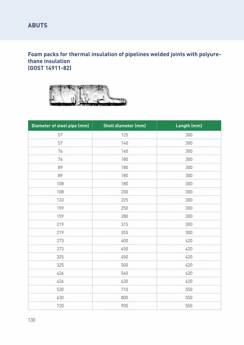
130
ABUTS
Foam packs for thermal insulation of pipelines welded joints with polyure-thane insulation (GOST 14911-82)
Diameter of steel pipe (mm) Shell diameter (mm) Length (mm)
57 125 300
57 140 300
76 140 300
76 180 300
89 180 300
89 180 300
108 180 300
108 200 300
133 225 300
159 250 300
159 280 300
219 315 300
219 355 300
273 400 420
273 450 420
325 450 420
325 500 420
426 560 420
426 630 420
530 710 550
630 800 550
720 900 550
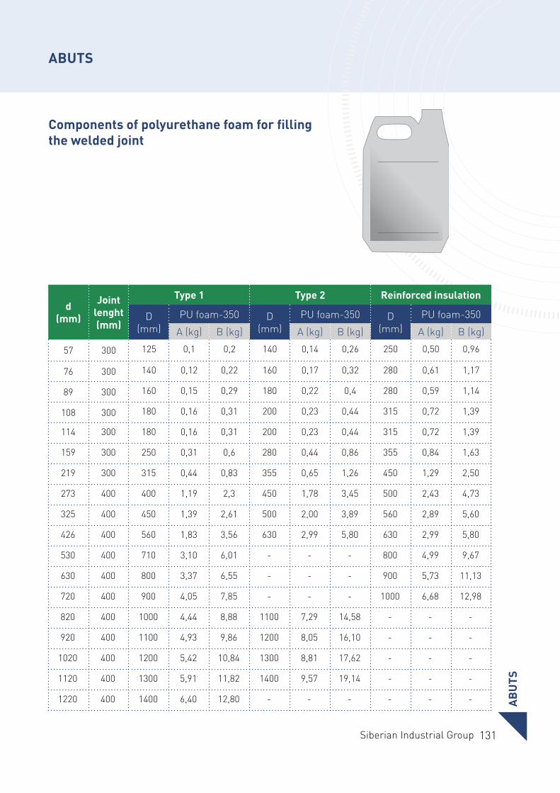
131Siberian Industrial Group
AB
UTS
ABUTS
Components of polyurethane foam for filling the welded joint
d (mm)
Joint lenght (mm)
Type 1 Type 2 Reinforced insulation
D (mm)
PU foam-350 D (mm)
PU foam-350 D (mm)
PU foam-350
А (kg) В (kg) А (kg) В (kg) А (kg) В (kg)
57 300 125 0,1 0,2 140 0,14 0,26 250 0,50 0,96
76 300 140 0,12 0,22 160 0,17 0,32 280 0,61 1,17
89 300 160 0,15 0,29 180 0,22 0,4 280 0,59 1,14
108 300 180 0,16 0,31 200 0,23 0,44 315 0,72 1,39
114 300 180 0,16 0,31 200 0,23 0,44 315 0,72 1,39
159 300 250 0,31 0,6 280 0,44 0,86 355 0,84 1,63
219 300 315 0,44 0,83 355 0,65 1,26 450 1,29 2,50
273 400 400 1,19 2,3 450 1,78 3,45 500 2,43 4,73
325 400 450 1,39 2,61 500 2,00 3,89 560 2,89 5,60
426 400 560 1,83 3,56 630 2,99 5,80 630 2,99 5,80
530 400 710 3,10 6,01 - - - 800 4,99 9,67
630 400 800 3,37 6,55 - - - 900 5,73 11,13
720 400 900 4,05 7,85 - - - 1000 6,68 12,98
820 400 1000 4,44 8,88 1100 7,29 14,58 - - -
920 400 1100 4,93 9,86 1200 8,05 16,10 - - -
1020 400 1200 5,42 10,84 1300 8,81 17,62 - - -
1120 400 1300 5,91 11,82 1400 9,57 19,14 - - -
1220 400 1400 6,40 12,80 - - - - - -
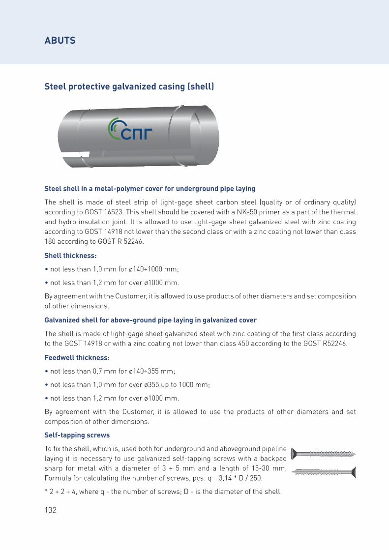
132
Steel protective galvanized casing (shell)
Steel shell in a metal-polymer cover for underground pipe laying
The shell is made of steel strip of light-gage sheet carbon steel (quality or of ordinary quality) according to GOST 16523. This shell should be covered with a NK-50 primer as a part of the thermal and hydro insulation joint. It is allowed to use light-gage sheet galvanized steel with zinc coating according to GOST 14918 not lower than the second class or with a zinc coating not lower than class 180 according to GOST R 52246.
Shell thickness:
• not less than 1,0 mm for ø140÷1000 mm;
• not less than 1,2 mm for over ø1000 mm.
By agreement with the Customer, it is allowed to use products of other diameters and set composition of other dimensions.
Galvanized shell for above-ground pipe laying in galvanized cover
The shell is made of light-gage sheet galvanized steel with zinc coating of the first class according to the GOST 14918 or with a zinc coating not lower than class 450 according to the GOST R52246.
Feedwell thickness:
• not less than 0,7 mm for ø140÷355 mm;
• not less than 1,0 mm for over ø355 up to 1000 mm;
• not less than 1,2 mm for over ø1000 mm.
By agreement with the Customer, it is allowed to use the products of other diameters and set composition of other dimensions.
ABUTS
Self-tapping screws
To fix the shell, which is, used both for underground and aboveground pipeline laying it is necessary to use galvanized self-tapping screws with a backpad sharp for metal with a diameter of 3 ÷ 5 mm and a length of 15-30 mm. Formula for calculating the number of screws, pcs: q = 3,14 * D / 250.
* 2 + 2 + 4, where q - the number of screws; D - is the diameter of the shell.
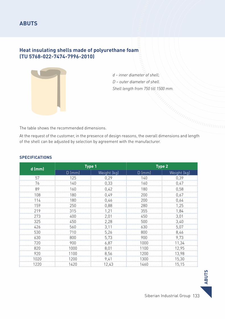
133Siberian Industrial Group
Heat insulating shells made of polyurethane foam (TU 5768-022-7474-7996-2010)
The table shows the recommended dimensions.
At the request of the customer, in the presence of design reasons, the overall dimensions and length of the shell can be adjusted by selection by agreement with the manufacturer.
SPECIFICATIONS
d (mm)Type 1 Type 2
D (mm) Weight (kg) D (mm) Weight (kg)57 125 0,29 140 0,3976 140 0,33 160 0,4789 160 0,42 180 0,58
108 180 0,49 200 0,67114 180 0,46 200 0,64159 250 0,88 280 1,25219 315 1,21 355 1,84273 400 2,01 450 3,01325 450 2,28 500 3,40426 560 3,11 630 5,07530 710 5,26 800 8,46630 800 5,73 900 9,73720 900 6,87 1000 11,34820 1000 8,01 1100 12,95920 1100 8,56 1200 13,98
1020 1200 9,41 1300 15,301220 1420 12,43 1460 15,15
d – inner diameter of shell; D – outer diameter of shell. Shell length from 750 till 1500 mm.
AB
UTS
ABUTS
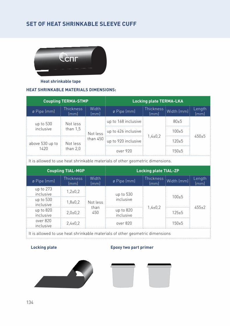
134
SET OF HEAT SHRINKABLE SLEEVE CUFF
Heat shrinkable tape
HEAT SHRINKABLE MATERIALS DIMENSIONS:
Coupling ТЕRMA-STMP Locking plate ТЕRMA-LKA
ø Pipe (mm) Thickness (mm)
Width (mm) ø Pipe (mm) Thickness
(mm) Width (mm) Length (mm)
up to 530 inclusive
Not less than 1,5
Not less than 450
up to 168 inclusive
1,4±0,2
80±5
450±5up to 426 inclusive 100±5
above 530 up to 1420
Not less than 2,0
up to 920 inclusive 120±5
over 920 150±5
It is allowed to use heat shrinkable materials of other geometric dimensions.
Coupling ТIAL-MGP Locking plate ТIAL-ZP
ø Pipe (mm) Thickness (mm)
Width (mm) ø Pipe (mm) Thickness
(mm) Width (mm) Length (mm)
up to 273 inclusive 1,2±0,2
Not less than 450
up to 530 inclusive
1,4±0,2
100±5
455±2
up to 530 inclusive 1,8±0,2
up to 820 inclusive 2,0±0,2 up to 820
inclusive 125±5
over 820 inclusive 2,4±0,2 over 820 150±5
It is allowed to use heat shrinkable materials of other geometric dimensions
Locking plate Epoxy two part primer
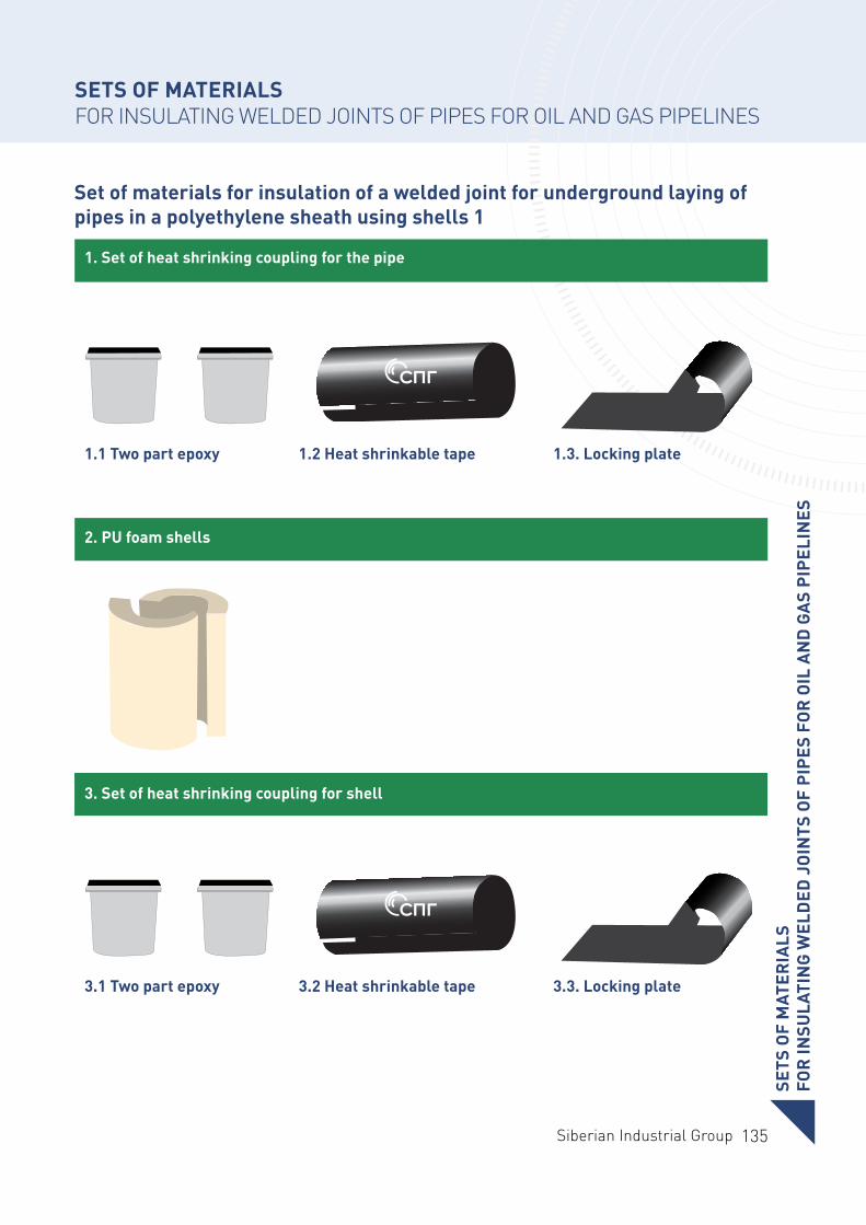
135Siberian Industrial Group
SETS OF MATERIALSFOR INSULATING WELDED JOINTS OF PIPES FOR OIL AND GAS PIPELINES
1.1 Two part epoxy
3.1 Two part epoxy
1.2 Heat shrinkable tape
3.2 Heat shrinkable tape
1.3. Locking plate
3.3. Locking plate
Set of materials for insulation of a welded joint for underground laying of pipes in a polyethylene sheath using shells 1
1. Set of heat shrinking coupling for the pipe
2. PU foam shells
3. Set of heat shrinking coupling for shellSE
TS O
F M
ATER
IALS
FOR
INSU
LATI
NG
WEL
DED
JO
INTS
OF
PIPE
S FO
R O
IL A
ND
GA
S PI
PELI
NES
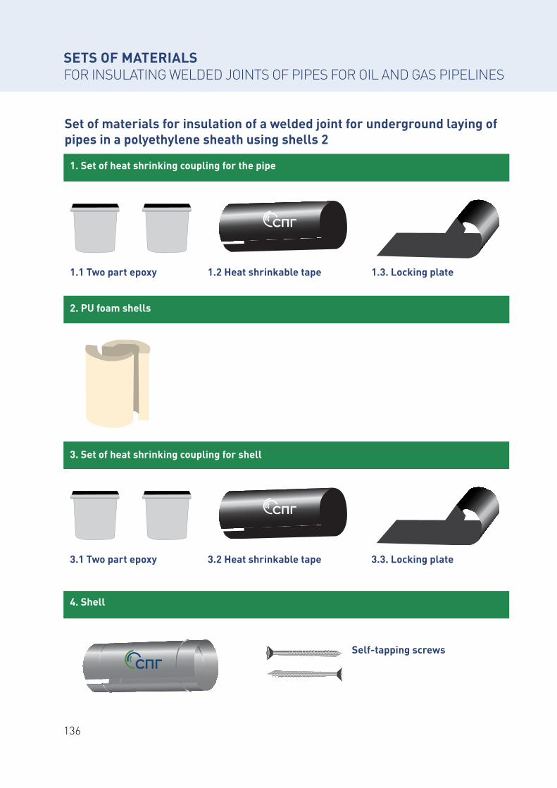
136
SETS OF MATERIALSFOR INSULATING WELDED JOINTS OF PIPES FOR OIL AND GAS PIPELINES
1.1 Two part epoxy
3.1 Two part epoxy
1.2 Heat shrinkable tape
3.2 Heat shrinkable tape
Self-tapping screws
1.3. Locking plate
3.3. Locking plate
Set of materials for insulation of a welded joint for underground laying of pipes in a polyethylene sheath using shells 2
1. Set of heat shrinking coupling for the pipe
2. PU foam shells
3. Set of heat shrinking coupling for shell
4. Shell
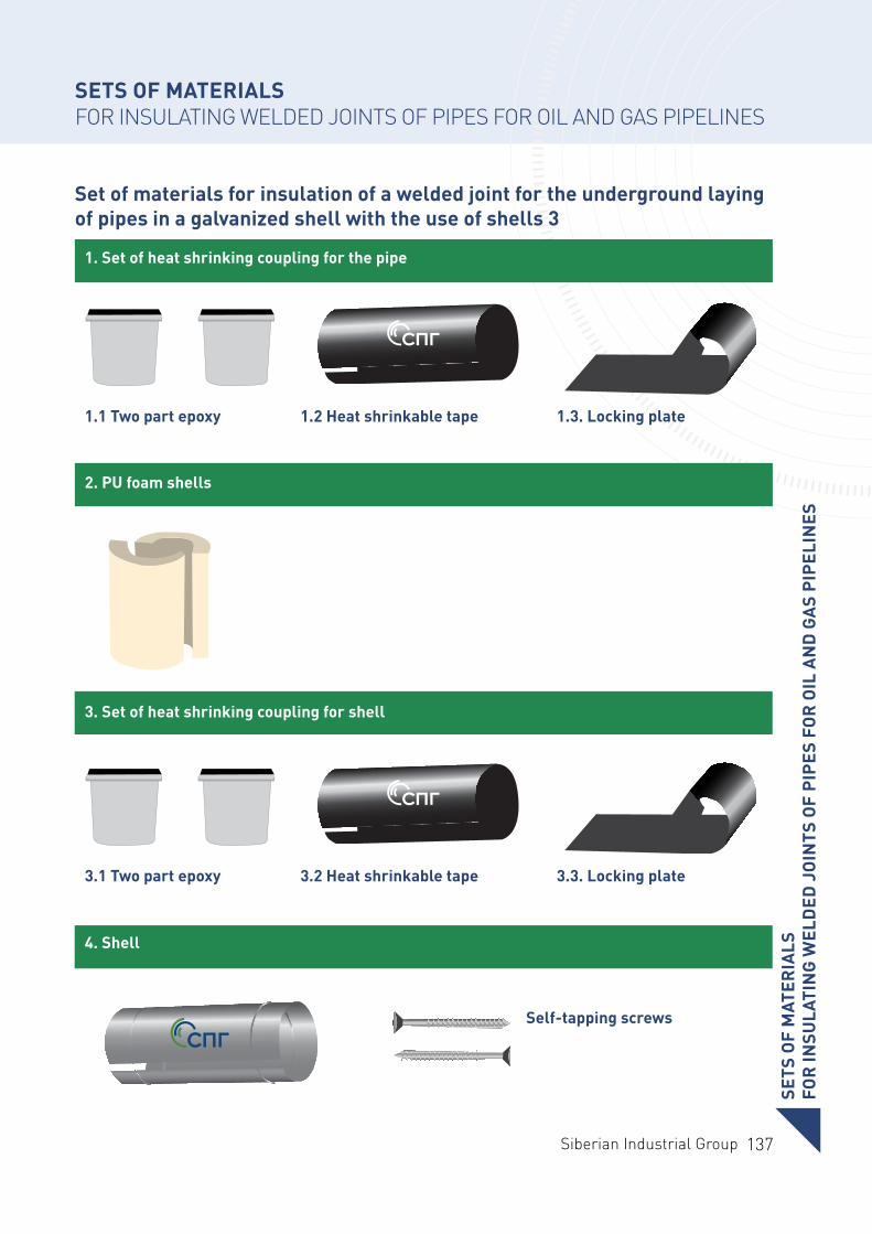
137Siberian Industrial Group
SETS OF MATERIALS FOR INSULATING WELDED JOINTS OF PIPES FOR OIL AND GAS PIPELINES
1.1 Two part epoxy
3.1 Two part epoxy
1.2 Heat shrinkable tape
3.2 Heat shrinkable tape
Self-tapping screws
1.3. Locking plate
3.3. Locking plate
Set of materials for insulation of a welded joint for the underground laying of pipes in a galvanized shell with the use of shells 3
1. Set of heat shrinking coupling for the pipe
2. PU foam shells
3. Set of heat shrinking coupling for shell
4. Shell
SETS
OF
MAT
ERIA
LSFO
R IN
SULA
TIN
G W
ELD
ED J
OIN
TS O
F PI
PES
FOR
OIL
AN
D G
AS
PIPE
LIN
ES
138
PARTNERS
WE COOPERATE THROUGHOUT RUSSIA
Siberian Industrial Group works with many large companies in Russia and the CIS countries. The strategic partners of SIG are the leading Russian metallurgical and oil and gas enterprises.
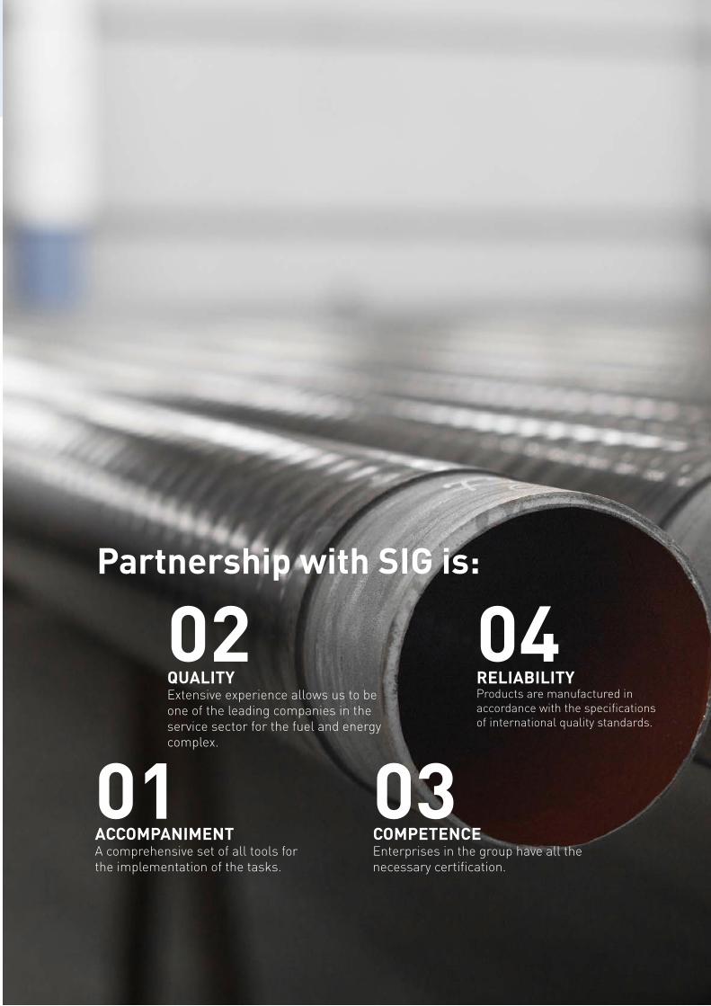
139Siberian Industrial Group
02
03
04
01
Partnership with SIG is:
QUALITY Extensive experience allows us to be one of the leading companies in the service sector for the fuel and energy complex.
COMPETENCE Enterprises in the group have all the necessary certification.
RELIABILITYProducts are manufactured in accordance with the specifications of international quality standards.
ACCOMPANIMENTA comprehensive set of all tools for the implementation of the tasks.
SIBERIAN INDUSTRIAL GROUP
www.aospg.ru
Tel: +7 (495)-230-75-01
Adress: Odesskaya st. 2, Moscow
E-mail: [email protected]
© AO Siberian Industrial Group, 2019This catalog contains information on products sold by AO Siberian Industrial Group. All data presented in the catalog are purely informational in nature and are not exhaustive. For more information, please contact the company representatives. AO Siberian Industrial Group reserves the right at any time without special notice to make changes, delete, correct, supplement, or in any other way update the information placed in all sections of this catalog. The use of information placed in this catalog can be carried out only subject to the requirements of the laws of the Russian Federation on copyright and intellectual property. It is the property of AO Siberian Industrial Group (Joint-Stock Company).