Embed Size (px)
Citation preview

2/3/2016
1
ABX 2015 Henri Fennell, CSI/CDT
Henri is an architect and building envelope specialist with over forty years of experience in the construction industry. He was a pioneer in the solar industry, introduced the installation technique for field-applied closed-cell closed-cavity-fill polyurethane foam and has designed and constructed a net-zero energy research structure in Antarctica. He has four energy-related U.S. patents.
1. First spray foam project was in 1971
2. Foam manufacturing from 1973 to 1979
3. Foam contracting and BE consulting from 1979 to 2009
– Developed the method for injecting closed-cell foam on site
– Installed ~ 5 million pounds of foam
4. Foam and BE commissioning from 2009 to present
5. Noteworthy foam projects include:
– 1977 net-zero solar project in Boston, The Big Dig, 4 American Ski Grande Hotels in the Northeast, Net-zero energy weather station in Antarctica, The Guggenheim Museum
6. Two US patents and numerous technical papers related to foam & foam QA
HCF foam experience
The challenges of creating the perfect conditions for proper machine processing polyurethane foam
By: Henri Fennell, CSI/CDT © H. C. Fennell 2016
16 Course Description
The challenges of creating the perfect conditions for properly machine processing polyurethane foam
This session will introduce the most common causes of problems in field-applied polyurethane foam plastic installations and present guidelines for ensuring proper chemical processing, the most common source of problems. It will start with an overview of the parameters that the foam’s chemistry requires for proper processing, then discuss the implications of these needs on how the equipment is set up and used, and how to verify that the processing parameters are being met. We will review industry-standard quality control procedures and then demonstrate additional methods that installers can use to ensure and verify proper processing.
Copyright Materials
This presentation and the related handout material is
protected by US and International Copyright laws.
Reproduction, distribution, display and use of the
presentation and the related handout material without
written permission of the speaker is prohibited.
© HC Fennell Consulting, LLC 2016
www.polyurethanefoamconsulting.com
The challenges of creating the perfect conditions for properly machine processing polyurethane
foam
Introduction
• Where does Processing fit in to an SPF project – Safety – Application Design/Building Science – Preparation – Equipment – Processing – Installation – Follow-up
• Note: Installation comes after processing!

2/3/2016
2
Processing vs. Installation
The Installation
The processing system
The foam industry relies on this
equipment to provide processing
quality Common problems
and causes
Let’s start with a few train wrecks! Note, these are not
common, but I have to solve these problems all too often.
Causes of foam problems
1. Lack of national ANSI standards and certifications 2. Lack of installer training and/or experience
– The “Cleveland Museum experience”
3. Manufacturer issues (foam and equipment) – Documentation – Tolerances not defined – Critical parameter feedback and fault-protection engineering controls not provided
4. Design issues – Product selection (Purfil spray foam?) – Installer qualifications not specified – Material compatibility and substrate conditions – Building Science implications (hybrid systems, unvented slopes) – Documentation and guarantees not addressed – Design intent not clear (R-value vs. thickness?) – Not code compliant
5. Price-driven marketplace (price vs. quality) 6. Distributors (different standards than manufacturers) 7. GCs lack experience with subcontracting foam installations
– No standard work requirements in bid solicitations – No in-house quality assurance protocols
8. Lack of barrier inspections by building officials
Common problems and causes
Unrelated causes blamed
on foam installations

2/3/2016
3
Causes of problems
Design - HVAC
What’s wrong with these pictures?
Building Science cause – mixed insulation
Project #2
Moisture
Building Science cause – mixed insulation
Common problems
and causes
Installation issues
Foam Problem – Processing or installation?
Thermal Shock and
pass thickness
Causes of problems

2/3/2016
4
Preparation problem
Pass thickness failure
Deep rim joist design with a spray foam spec.
Design for a pass thickness failure
One 11” pass with an 1-1/2” lift spray foam product
Too hot - burnout
2012 Cape Cod attic fire

2/3/2016
5
Scorching or burn-out
Common problems
and causes
Processing issues
Infrared locates off-ratio material Off ratio - fluctuations
Off ratio - fluctuations Off ratio - fluctuations
Layers of A-rich, good quality, and B-rich foam

2/3/2016
6
Off ratio - fluctuations
Frozen pipes inside
$150,000 removal and replacement – house and garage apartment
The remediation process - removal
Flat bar and a
hammer worked the
best
Off ratio – B-rich
Low-tech froth equipment with no
monitoring capabilities
$8,500 removal and replacement
The cost of remediation Removal was required as this
was a Type II problem
$30,000 removal and permanent Owner injury
Short-term off-ratio event Short-term off-ratio event
$3,000 repair and lost reputation

2/3/2016
7
Intermittent processing problem Processing affects dimensional stability
Before
Elongated cells are weaker perpendicular to the grain, and hot box exposure causes the material to shrink laterally.
After
Processing affects dimensional stability
Before
After
Processing affects dimensional stability
Before
After
Processing – Step #1 Understanding the
processing parameters
What does the chemistry require?
SPF is a two-component chemical system that requires:
• Properly conditioned chemicals
• Precise proportioner performance
• Proper delivery of the chemicals from the proportioner to the gun
• A complete chemical reaction of all of the components
2/3/2016
8
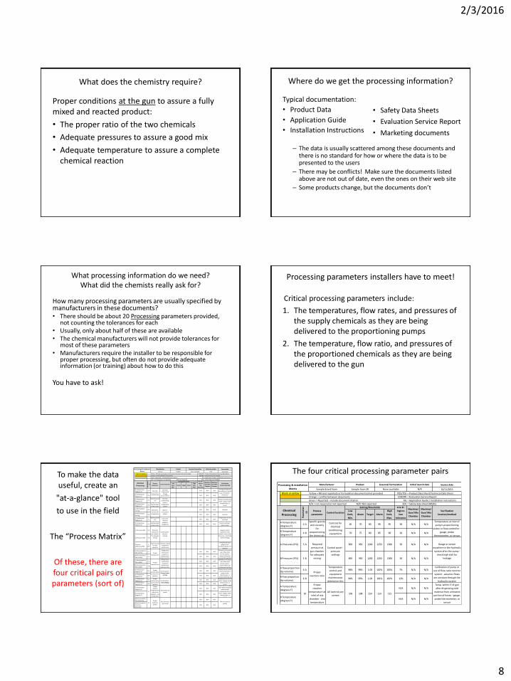
What does the chemistry require?
Proper conditions at the gun to assure a fully mixed and reacted product:
• The proper ratio of the two chemicals
• Adequate pressures to assure a good mix
• Adequate temperature to assure a complete chemical reaction
Where do we get the processing information?
Typical documentation:
• Product Data
• Application Guide
• Installation Instructions
– The data is usually scattered among these documents and there is no standard for how or where the data is to be presented to the users
– There may be conflicts! Make sure the documents listed above are not out of date, even the ones on their web site
– Some products change, but the documents don’t
• Safety Data Sheets
• Evaluation Service Report
• Marketing documents
What processing information do we need? What did the chemists really ask for?
How many processing parameters are usually specified by manufacturers in these documents? • There should be about 20 Processing parameters provided,
not counting the tolerances for each • Usually, only about half of these are available • The chemical manufacturers will not provide tolerances for
most of these parameters • Manufacturers require the installer to be responsible for
proper processing, but often do not provide adequate information (or training) about how to do this
You have to ask!
Critical processing parameters include:
1. The temperatures, flow rates, and pressures of the supply chemicals as they are being delivered to the proportioning pumps
2. The temperature, flow ratio, and pressures of the proportioned chemicals as they are being delivered to the gun
Processing parameters installers have to meet!
Source date
10/11/2015
Blank or yellow Yellow = NR (not reported) or formulation documented not provided PDS/TDS = Product Data Sheet/Technical Data Sheet
Orange = conflict between documents ESR/IRR = Evaluation Service Report
Green = Reported - include document citation AG = Application Guide / Installation instructions
N/A = not required or not reported N/R= Not reported SDS = Safety data sheet (MSDS)
Low
limit,
Min.
Alarm Target Alarm
High
limit,
Max.
A Temperature
(degrees F)1 A N/A N/A N/A
B Temperature
(degrees F)1 B N/A N/A N/A
A Temperature
(degrees F)2 A N/A N/A N/A
B Temperature
(degrees F)2 B N/A N/A N/A
A Recirculation/
mixing3 A N/A N/A N/A Operator
B Recirculation/
mixing3 B N/A N/A N/A Operator
A Temperature
(degrees F)4 A N/A N/A N/A
B Temperature
(degrees F)4 B N/A N/A N/A
A Pressures (PSI) 5 A
B Pressures (PSI) 5 B
Pressure
difference (PSI)
Helps maintain
on-ratio
operation
Indicator or good
equipment
maintenance
Compare pressure
gauges if not
monitored (Insite or P-
monitor)
A flow proportion
(by volume)6 A N/A N/A N/A
B flow proportion
(by volume)6 B N/A N/A N/A
A flow proportion
(by weight)7 A N/A N/A N/A
B flow proportion
(by weight)7 B N/A N/A N/A
A Temperature
(degrees F)8 A N/A N/A N/A
B Temperature
(degrees F)8 B N/A N/A N/A
A Temperature
(degrees F)9 A N/A N/A N/A
B Temperature
(degrees F)9 B N/A N/A N/A
A Temperature
(degrees F)N/A N/A N/A
B Temperature
(degrees F)N/A N/A N/A
Reactivity profile -
Rise (Seconds)N/A N/A N/A
Reactivity profile -
Tack free
(Seconds)
N/A N/A N/A
Proper
reaction temp.
at inlet of mix
chamber
All parameters
are correct
Temperature
control and
equipment
maintenance
determine this
Proper
reaction ratio
Required
pressure at
gun chamber
for adequate
mixing
Proper
reaction ratio
Mix and reaction
quality
All controls are
correct
Control panel -
Primary heater
settings
Control panel -
Hose settings
Calibration of pump or
use of flow ratio
monitor system -
assumes flows are
constant through the
Calibration of pump or
use of flow ratio
monitor system -
assumes flows are
constant through the
Temperature at outlet
of primary heater /
gauge, probe
thermometer, or
sensor, but temp. at
Temp. within 5' of gun
after dispensing cold
material from
unheated portion of
hoses - gauge, probe
thermometer, or
sensor
Temperature within 5'
of gun / gauge, probe
thermometer, or
sensor
Proper
reaction
temperature at
inlet of mix
chamber - one
temperature
10
Gauge or sensor
anywhere in the
hydraulic system after
the pump - check high
stall for leakage
Control panel -
pressure
settings
Temperature
control and
equipment
maintenance
determine this
5
diff
Chemical
Processing
A to B :
high to
low
tolerance
Machine/
Gun/ Mix
Chamber
Machine/
Gun/ Mix
Chamber
Icynene
Processing & installation
Matrix
Product
Par
ame
ter
ID
Process
parameterControl location
Setting/thresholds
Manufacturer
ProSeal
Initial launch date
N/R
Seasonal formulation
None available
Verification
location/method
Specific gravity
for
proportioning
the chemicals
at the proper
Chemical
health before
conditioning
Specific gravity
for
proportioning
the chemicals
at the proper
Chemical
conditioning
space or
temperature
control
Control for
chemical
condition
equipment
Average of high and
low readings in center
mass of container -
Immersion
thermometer/sensor
Temperature at inlet
of pump's
proportioning piston
or flow controller -
gauge, probe
Chemical conditioning
space - gauge, probe
thermometer, or
sensor
Chemical
shipping and
storage
environments
Uniformity -
material and
temperature
Mixer or
recirculation
system
Proper
reactivity
profile
11
Proper
reaction temp.
at inlet of mix
chamber
To make the data useful, create an
"at-a-glance" tool
to use in the field
The “Process Matrix”
Of these, there are four critical pairs of parameters (sort of)
The four critical processing parameter pairs
Source date
10/11/2015
Blank or yellow Yellow = NR (not reported) or formulation documented not provided PDS/TDS = Product Data Sheet/Technical Data Sheet
Orange = conflict between documents ESR/IRR = Evaluation Service Report
Green = Reported - include document citation AG = Application Guide / Installation instructions
N/A = not required or not reported N/R= Not reported SDS = Safety data sheet (MSDS)
Low
limit,
Min.
Alarm Target Alarm
High
limit,
Max.
A Temperature
(degrees F)4 A 65 70 80 90 95 30 N/A N/A
B Temperature
(degrees F)4 B 70 75 80 85 90 20 N/A N/A
A Pressures (PSI) 5 A 850 950 1200 1250 1300 50 N/A N/A
B Pressures (PSI) 5 B 850 950 1200 1250 1300 50 N/A N/A
A flow proportion
(by volume)6 A 98% 99% 1.00 102% 105% 7% N/A N/A
B flow proportion
(by volume)6 B 90% 95% 1.00 101% 102% 12% N/A N/A
A Temperature
(degrees F)N/A N/A N/A
B Temperature
(degrees F)N/A N/A N/A
113 115
Temp. within 5' of gun
after dispensing cold
material from unheated
portion of hoses - gauge,
probe thermometer, or
sensor
10
Proper
reaction
temperature at
inlet of mix
chamber - one
temperature
All controls are
correct105 108 110
Verification
location/method
Calibration of pump or
use of flow ratio monitor
system - assumes flows
are constant through the
hydraulic system
Proper
reaction ratio
Temperature
control and
equipment
maintenance
determine this
Specific gravity
and viscosity
for
proportioning
the chemicals
Controls for
chemical
conditioning
equipment
Temperature at inlet of
pump's proportioning
piston or flow controller -
gauge, probe
thermometer, or sensor
Required
pressure at
gun chamber
for adequate
mixing
Control panel -
pressure
settings
Gauge or sensor
anywhere in the hydraulic
system after the pump -
check high stall for
leakage
Chemical
Processing
Par
ame
ter
ID
Process
parameterControl location
Initial launch date
Sample Brand foam Sample foam 2# None available N/R
Setting/thresholds A to B :
high to
low
tolerance
Machine/
Gun/ Mix
Chamber
Machine/
Gun/ Mix
Chamber
Processing & installation
Matrix
Manufacturer Product Seasonal formulation

2/3/2016
9
Critical processing parameter data includes:
1. The parameter name (A-side supply temperature)
2. The type of data (temperatures, flow rates, pressures, time, specific gravity, viscosity, etc.)
3. Optional – what controls the parameter (pump’s pre-heater control)
4. The Low, ideal, high, and “alarm” tolerances or thresholds for the parameters (60, 65, 75, 80, 85)
5. Special circumstances that may affect the tolerances (Mixer shape and output)
6. Optional – means of verification (thermometer)
Processing parameters installers have to meet!
Processing – Step #2 Pre-conditioning the
chemicals
Source date
10/11/2015
Blank or yellow Yellow = NR (not reported) or formulation documented not provided PDS/TDS = Product Data Sheet/Technical Data Sheet
Orange = conflict between documents ESR/IRR = Evaluation Service Report
Green = Reported - include document citation AG = Application Guide / Installation instructions
N/A = not required or not reported N/R= Not reported SDS = Safety data sheet (MSDS)
Low
limit,
Min.
Alarm Target Alarm
High
limit,
Max.
A Temperature
(degrees F)1 A 50 90 N/A N/A N/A
B Temperature
(degrees F)1 B 50 80 N/A N/A N/A
A Temperature
(degrees F)2 A 50 90 N/A N/A N/A
B Temperature
(degrees F)2 B 50 80 N/A N/A N/A
A Recirculation/
mixing3 A N/A N/A N/A Operator
B Recirculation/
mixing3 B N/A N/A N/A Operator
Within these limits
Within these limits
Within these limits
Within these limits
Processing & installation
Matrix
Product Initial launch date
N/R
Par
ame
ter
ID
Process
parameterControl location
Setting/thresholds
Manufacturer
ProSeal
Seasonal formulation
None available
Chemical
Processing
A to B :
high to
low
tolerance
Icynene
Verification
location/method
Chemical
health before
conditioning
Specific gravity
and viscosity
for
proportioning
the chemicals
Chemical
conditioning
space or
temperature
control
Average of high and
low readings in center
mass of container -
Immersion
thermometer/sensor
Chemical conditioning
space - gauge, probe
thermometer, or
sensor
Chemical
shipping and
storage
environments
Uniformity -
material and
temperature
Mixer or
recirculation
system
Not required
Not recommended
Machine/
Gun/ Mix
Chamber
Machine/
Gun/ Mix
Chamber
Storage and shipping parameters
Difference comes from concerns over boiling out the blowing agent from the B side
Processing – the steps Material preparation/conditioning
How to protect the supply chemicals
• Always maintain the material within the recommended temperature range
• Head-space blankets
– aka "Inert gas blanketing" (See AY-137 for more information)
– Reasons for A & B-side blanketing (its “crystal” clear)
– Head-space methods (dry air venting, desiccant cartridges, or N2 blanket)
Air Dryers There are three basic types
of automatic air dryers that will work for foam processing
Desiccant filter air dryer
Refrigerated air dryer
Membrane dryer
Replaceable desiccant air dryers
Avoid crystalized Isocyanate in your system
Air dryer and dry nitrogen for head space blanket
PVs can be kept under dry air or N2 pressure (up to 75 PSI) without placarding

2/3/2016
10
Avoid crystalized Isocyanate in your system
Nitrogen components for head space blanket
“Keep drums tightly closed when not in use and under dry air or nitrogen pressure of 2-3 psi after they have been opened.”
Processing – Step #2
Material storage and handling
• Maintain chemicals within recommended temperatures
– Avoids damage to the chemicals
– Extends Shelf life
• IT TAKES TIME! PB engineers indicate that it takes about 30 hours to heat or cool drums 15 degrees using air with a delta T of 15F
Kit temperature control
Quality control #2 – Verify the supply chemical temperatures with
thermometers or with engineering controls
More on measuring chemical temperatures in Step #3
Processing – Step #2 - pre-conditioning
Shipping and receiving
Maintain chemicals within recommended temperatures
Require "Protect from freezing" or "Min./max. temperature" on P.O.s
Check the chemical temperatures before accepting delivery – reject materials if below freezing (?)
Processing – Step #3 Conditioning the
chemicals

2/3/2016
11
Processing – Step #3a Maintain the proper
temperatures
The four critical processing parameter pairs Source date
10/11/2015
Blank or yellow Yellow = NR (not reported) or formulation documented not provided PDS/TDS = Product Data Sheet/Technical Data Sheet
Orange = conflict between documents ESR/IRR = Evaluation Service Report
Green = Reported - include document citation AG = Application Guide / Installation instructions
N/A = not required or not reported N/R= Not reported SDS = Safety data sheet (MSDS)
Low
limit,
Min.
Alarm Target Alarm
High
limit,
Max.
A Temperature
(degrees F)4 A 65 70 80 90 95 30 N/A N/A
B Temperature
(degrees F)4 B 70 75 80 85 90 20 N/A N/A
A Pressures (PSI) 5 A 850 950 1200 1250 1300 50 N/A N/A
B Pressures (PSI) 5 B 850 950 1200 1250 1300 50 N/A N/A
A flow proportion
(by volume)6 A 98% 99% 1.00 102% 105% 7% N/A N/A
B flow proportion
(by volume)6 B 90% 95% 1.00 101% 102% 12% N/A N/A
A Temperature
(degrees F)N/A N/A N/A
B Temperature
(degrees F)N/A N/A N/A
113 115
Temp. within 5' of gun
after dispensing cold
material from unheated
portion of hoses - gauge,
probe thermometer, or
sensor
10
Proper
reaction
temperature at
inlet of mix
chamber - one
temperature
All controls are
correct105 108 110
Calibration of pump or
use of flow ratio monitor
system - assumes flows
are constant through the
hydraulic system
Proper
reaction ratio
Temperature
control and
equipment
maintenance
determine this
Specific gravity
for
proportioning
the chemicals
at the proper
Control for
chemical
condition
equipment
Temperature at inlet of
pump's proportioning
piston or flow controller -
gauge, probe
thermometer, or sensor
Required
pressure at
gun chamber
for adequate
mixing
Control panel -
pressure
settings
Gauge or sensor
anywhere in the hydraulic
system after the pump -
check high stall for
leakage
Setting/thresholds A to B :
high to
low
tolerance
Machine/
Gun/ Mix
Chamber
Machine/
Gun/ Mix
Chamber
Verification
location/method
Chemical
Processing
Par
ame
ter
ID
Process
parameterControl location
Initial launch date
Sample Brand foam Sample foam 2# None available N/R
Processing & installation
Matrix
Manufacturer Product Seasonal formulation
The processing system
A B
Conditioning - Measure supply chemical temperatures at the inlets of the A & B transfer pumps
Processing – Step #3a
#3a Material preparation/conditioning
• Achieve and maintain the proper supply chemical temperatures
• This assures the right specific gravity and viscosity material will be provided to the positive-displacement pumps. This allows the proportioner to pump the correct volume of each chemical to the gun (1:1 "ratio" by volume)
Why do pressures and ratios change? Processing – Step #3a
How to maintain the supply chemical temperatures once they are in the rig • Always start with pre-conditioned chemicals
• Maintain temperatures inside the rig at the proper supply chemical temperature (Electric heaters, Espar heaters)
• Protect the chemicals from cold sources once placed in the rig
• Add heat to the chemicals as required to maintain the proper temperatures
• Distribute heating sources evenly – avoid local hot spots to avoid boiling the 245fa blowing agent

2/3/2016
12
Supply drums delivered to the site too cold
Torpedo heater in use to try to warm up chemicals so the work can begin
Always start with pre-conditioned chemicals
12-volt diesel heater
https://youtu.be/guN0ZtemeO4?list=PL3k1IfMx4RIXCuXwak05vRlrwOqY505vv
Maintain temperatures inside the rig
40,000 BTU heater runs off of circulating diesel engine coolant
– this system can run while traveling to and from the site
Maintain temperatures inside the rig
12-volt fan
1.2 KW - 120 volt radiant electric
panels (8 < $100, < 8 lb. each)
Processing – Step #3a
Heating system options – track how much time is required for each option?
• Radiant floor and wall heaters, band heaters, blanket heaters
• Immersion heaters?
• Arctic Pack in-line heaters. Are they a good idea?
• Don't forget about summer time cooling requirements
Maintain the supply chemical temperatures once they are in the rig
Various electric band, blanket, and floor base
heaters
Supply drums delivered to the site too cold
Overheating drums can create a serious
pressure hazard
High temperature localized heat sources can damage the chemicals and boil out the blowing agent – reduces yield.
Always start with pre-conditioned chemicals

2/3/2016
13
Add heat to the chemicals as required
Supplement supply container heaters, if necessary
In-line preheater with built-in temperature control
Add heat to the chemicals as required
• Heat from the top, side, or bottom? Multiple sides?
• What is the maximum localized temperature you can apply to the drum without damaging the chemicals?
• Heating the B side in closed-cell foam is more problematic due to boiling the blowing agent, over-pressurizing the drums
• Totes are more problematic when raising the core temperature. Why?
• Pressure vessels are the easiest to manage
Quality control #3a – Verify the supply
chemical temperatures are on spec.
Processing – Step #3a Material preparation/conditioning
How to verify supply chemical temperatures?
• How to measure the supply chemical temperatures
– Tools
– Where to measure
• Quote from the documentation…
– “Cold chemicals can cause poor mixing, pump cavitation, or other process problems due to higher viscosity at lower temperatures.”
#3 Material preparation/conditioning
Temperature readings during recirculation indicate chemical temperature once the readings stabilize
In-line thermometers
In-barrel thermometers
IR surface temperature thermometers
Supply inlet temperatures
Preheater settings do not impact the supply chemical temperatures unless you recirculate
Supply chemical temperatures

2/3/2016
14
Processing – Step #3a Conditioning
How to verify supply chemical temperatures?
55-gallon drums (Degrees F)
55-gallon drums
(Degrees F) Diff.
Ambient 21.0 25.0
Thermostat inside Rig
65/72 Rear door
open 1 hour
Top in liquid 72.0 72.0 0.0
Top on side 73.0 53.8 -19.2
Middle in liquid
N/M N/M
Middle on side
67.0 42.2 -24.8
Bottom in liquid
58.0 58.0 0.0
Bottom on side
60.0 43.0 -17.0
Processing – Step #3a Conditioning
Test for chemical temperature uniformity
5,000# Totes (Degrees F)
5,000# Totes (Degrees F)
Diff.
Ambient 21.0 25.0
Thermostat inside Rig
65/72 Rear door
open 1 hour
Top in liquid
Head space Head space
Top on side Not full Not full
Middle in liquid
65.0 66.0 1.0
Middle on side
65.0 53.4 -11.6
Bottom in liquid
60.5 60.5 0.0
Bottom on side
60.2 40.6 -19.6
Tests indicate about a .42 average degrees rise per hour in a hot room
maintained at 15 degrees above the 55-
gallon storage container starting point (about
two hours per degree)
How to verify supply that the proper chemical temperatures are being delivered to the pump?
Processing – Step #3a (Continued) Where to check supply temperature
Why should you measure at the drums and at the proportioner pump inlets?
Proportioner
Pro
po
rtio
ner
Verifying supply inlet temperatures
Supply chemical temperatures
Processing – Step #3b Mix the chemicals
when recommended by the manufacturer

2/3/2016
15
Processing – Step #3b
How to achieve uniformity within the supply containers
– Maintain chemical component distribution - reduce stratification and separation of the chemical compounds
– Mixing - Low pressure recirculation • Minimize splash – return below the surface
of the liquid
• Draw from the bottom
• Start slow when the material is coldest
– Stirring/agitation • Minimize splash, stir at all levels or from the
bottom to the top (blade angles)
Recirculation through the hoses and gun manifold
Recirculation through the pump manifold
Pressure balance ports converted to recirculation
return lines. Is this the high or low pressure side of the pump?
Return (dip) tubes should extend to the bottom of the drum to avoid splashing the material - Why?
Note the strain relief coils on these hoses
Recirculation – through the gun manifold
Do not set the hose heat higher than the maximum chemical
storage temperature
These return (dip) tubes should also extend to the bottom of the drums
Use Jog mode or low pressure settings to recirculate material
Similar to using Jog mode during pump setup or bleeding the hoses
Caution – set heat “low” in either method to avoid boiling the blowing agent

2/3/2016
16
Caution – When using Jog mode or feed pumps – avoid over-pressuring the supply drums!
Jog mode is for bleeding the hoses, recirculation, or checking for leaks, but it is also useful for
calibrating a proportioner
Jog mode maximum pressure is 700 psi @ J10 See “J___5” on the pump
control
Processing – Step #3b
Mechanical mixing methods and equipment
Quality control #3b – Verify
supply chemical uniformity • Recirculate or stir for the period of time and at the
rate recommended by the manufacturer for the conditions at hand
• Ask the manufacturer for further instructions if the information is not provided in the installation manual (ideally in writing)
Processing – Step #4
Deliver the supply chemicals to the pump
Flow rates for supply/transfer pumps
Source date
10/11/2015
Blank or yellow Yellow = NR (not reported) or formulation documented not provided PDS/TDS = Product Data Sheet/Technical Data Sheet
Orange = conflict between documents ESR/IRR = Evaluation Service Report
Green = Reported - include document citation AG = Application Guide / Installation instructions
N/A = not required or not reported N/R= Not reported SDS = Safety data sheet (MSDS)
Low
limit,
Min.
Alarm Target Alarm
High
limit,
Max.
A Temperature
(degrees F)4 A 65 70 80 90 95 30 N/A N/A
B Temperature
(degrees F)4 B 70 75 80 85 90 20 N/A N/A
Transfer pump
flow rate (GPM)5 A
2X pump
flow rateN/A N/A N/A
Transfer pump
flow rate (GPM)5 B
2X pump
flow rateN/A N/A N/A
A Pressures (PSI) 6 A 850 950 1200 1250 1300 50 N/A N/A
B Pressures (PSI) 6 B 850 950 1200 1250 1300 50 N/A N/A
Pressure
difference (PSI)
Helps maintain
on-ratio
operation
Indicator or good
equipment
maintenance
N/A N/A N/A
Compare pressure
gauges if not
monitored (Insite or P-
monitor)
Required
pressure at
gun chamber
for adequate
mixing
Control panel -
pressure
settings
Gauge or sensor
anywhere in the
hydraulic system after
the pump - check high
stall for leakage
6 diff 50 or less
Specific gravity
for
proportioning
the chemicals
at the proper
Control for
chemical
condition
equipment
Temperature at inlet
of pump's
proportioning piston
or flow controller -
gauge, probe
Adequate
supply of
chemicals to
the
proportioner
Transfer pump
selection
N/A Manufactuer's
published flow rate
from the product
specificationsN/A
Setting/thresholds A to B :
high to
low
tolerance
Machine/
Gun/ Mix
Chamber
Machine/
Gun/ Mix
Chamber
Verification
location/method
Chemical
Processing
Par
ame
ter
ID
Process
parameterControl location
Initial launch date
Icynene ProSeal None available N/R
Processing & installation
Matrix
Manufacturer Product Seasonal formulation
A
The processing system
B
Transfer pumps supply chemicals to the proportioner - transfer pumps must be sized properly
Pumps, filters, hoses, and valves must be clean and operational to prevent restrictions on the supply side of the proportioner
B A

2/3/2016
17
The material feed system -Transfer the supply chemicals from drums, totes, or pressure vessels to the proportioner
• Must supply adequate material to the proportioner
– What is the minimum supply/transfer rate/value?
– Typical stick pumps provide 100 or 200 feed PSI (one or two stage). 200 PSI systems are less prone to cavitation.
– “Caution: If the material feed system cannot feed “A” and “B” components as required by the proportioner, cavitation will occur causing intermittent off-ratio foam and/or plugged equipment.” AY-137
Transferring material to the proportioner
• Manifold systems - never use one pump to supply multiple primary pumps unless: – Adequate flow and pressure can be provided
– You can verify that adequate flow and pressure are being provided to both proportioners
– The auto shut-down feature (some newer proportioners) can calculate stroke count for two-pumps
– The transfer pump pressures are less than 25% of the primary pump pressures
– Note: Supply/transfer pump failure will reduce supply to both Proportioners
The material feed system -Transfer the supply chemicals from pressure vessels to the proportioner
Pressure vessels (fleet tanks, day tanks, etc.)
• Verify that the pressure and hose sizes are adequate to deliver the minimum supply volume for the output of the proportioner. How?
The material feed system -Transfer the supply chemicals from drums, totes, or pressure vessels to the proportioner
Transfer methods
• Stick pumps
• Diaphragm pumps
• Pressure vessels (fleet tanks, day tanks, etc.)
Transferring material to the proportioner
Potential problems
• Filtration
• Temperature drop (impact on chemical viscosity)
• Pressure drop (low flow if plumbing is too small)
• Cavitation (hose restriction, broken foot valve, closed make-up air inlet, empty drum)
Transferring material to the proportioner
• Kinked hoses, broken transfer/feed pump, clogged ”Y” strainer, filters, etc. can restrict the supply side of the system
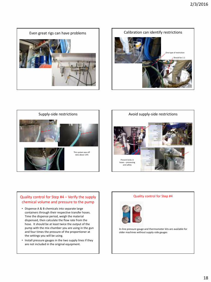
2/3/2016
18
Even great rigs can have problems
• Upstream restrictions
Calibration can identify restrictions
Should be 1:1
One type of restriction
Supply-side restrictions
This system was off ratio about 14%
Avoid supply-side restrictions
Prevent kinks in hoses – processing
and safety
Quality control for Step #4 – Verify the supply chemical volume and pressure to the pump
• Dispense A & B chemicals into separate large containers through their respective transfer hoses. Time the dispense period, weigh the material dispensed, then calculate the flow rate from the hose. It should be at least twice the output of the pump with the mix chamber you are using in the gun and four times the pressure of the proportioner at the settings you will be using.
• Install pressure gauges in the two supply lines if they are not included in the original equipment.
Quality control for Step #4
In-line pressure gauge and thermometer kits are available for older machines without supply-side gauges

2/3/2016
19
Processing – Step #5 Pressurize the
chemicals
The four critical processing parameter pairs Source date
10/11/2015
Blank or yellow Yellow = NR (not reported) or formulation documented not provided PDS/TDS = Product Data Sheet/Technical Data Sheet
Orange = conflict between documents ESR/IRR = Evaluation Service Report
Green = Reported - include document citation AG = Application Guide / Installation instructions
N/A = not required or not reported N/R= Not reported SDS = Safety data sheet (MSDS)
Low
limit,
Min.
Alarm Target Alarm
High
limit,
Max.
A Temperature
(degrees F)4 A 65 70 80 90 95 30 N/A N/A
B Temperature
(degrees F)4 B 70 75 80 85 90 20 N/A N/A
A Pressures (PSI) 5 A 850 950 1200 1250 1300 50 N/A N/A
B Pressures (PSI) 5 B 850 950 1200 1250 1300 50 N/A N/A
A flow proportion
(by volume)6 A 98% 99% 1.00 102% 105% 7% N/A N/A
B flow proportion
(by volume)6 B 90% 95% 1.00 101% 102% 12% N/A N/A
A Temperature
(degrees F)N/A N/A N/A
B Temperature
(degrees F)N/A N/A N/A
113 115
Temp. within 5' of gun
after dispensing cold
material from unheated
portion of hoses - gauge,
probe thermometer, or
sensor
10
Proper
reaction
temperature at
inlet of mix
chamber - one
temperature
All controls are
correct105 108 110
Calibration of pump or
use of flow ratio monitor
system - assumes flows
are constant through the
hydraulic system
Proper
reaction ratio
Temperature
control and
equipment
maintenance
determine this
Specific gravity
for
proportioning
the chemicals
at the proper
Control for
chemical
condition
equipment
Temperature at inlet of
pump's proportioning
piston or flow controller -
gauge, probe
thermometer, or sensor
Required
pressure at
gun chamber
for adequate
mixing
Control panel -
pressure
settings
Gauge or sensor
anywhere in the hydraulic
system after the pump -
check high stall for
leakage
Setting/thresholds A to B :
high to
low
tolerance
Machine/
Gun/ Mix
Chamber
Machine/
Gun/ Mix
Chamber
Verification
location/method
Chemical
Processing
Par
ame
ter
ID
Process
parameterControl location
Initial launch date
Sample Brand foam Sample foam 2# None available N/R
Processing & installation
Matrix
Manufacturer Product Seasonal formulation
The processing system
B A
The pressure at the pumps and the gun should be the same given that this is a hydraulic system Verify the pressure with the gauges located at the primary pumps
B
A
Quality control #5 – Verify the
pressure of the chemicals provided to the gun by
manually reading the gauges or with engineering controls
The proportioner pumping system Supplying the chemicals to the gun
The Pressures of A and B are supposed to be close to the same and high enough to assure that the chemicals will be equally and fully mixed.
Therefore, our machines have to provide adequate pressure to:
• Overcome the pressure drop in the hoses and the gun
• Mix the chemicals properly
• Maintain adequate pattern control at the gun
• Dispense material with specialty adapters and delivery systems
Verify and adjust initial pressures
A 100 psi differential is best practice. A 200 psi differential approaches where you could have a cross over in the gun.

2/3/2016
20
Why do pressures go off?
… “could be a clog in the Y Strainer, an obstruction in the fluid hose or gun, or you’re out of material.
Double-acting hydraulic piston pump
Why do pressures go off? Why do pressures go off?
This is why you can’t rely on pressures to be sure of the material ratio, but the pressures can provide an indication of when the system’s
performance has changed.
Only positive-displacement flow meters can provide accurate feedback about ratio. The
possibility of having unbalanced pressures also indicates that virtually no equipment always
operates at a 1:1 ratio
Processing – Step #6 Proportion the
chemicals
The processing system
A
Primary pumps “proportion” the chemicals and supply them to the gun at the prescribed ratio (theoretically 1:1)
B

2/3/2016
21
The four critical processing parameter pairs Source date
10/11/2015
Blank or yellow Yellow = NR (not reported) or formulation documented not provided PDS/TDS = Product Data Sheet/Technical Data Sheet
Orange = conflict between documents ESR/IRR = Evaluation Service Report
Green = Reported - include document citation AG = Application Guide / Installation instructions
N/A = not required or not reported N/R= Not reported SDS = Safety data sheet (MSDS)
Low
limit,
Min.
Alarm Target Alarm
High
limit,
Max.
A Temperature
(degrees F)4 A 65 70 80 90 95 30 N/A N/A
B Temperature
(degrees F)4 B 70 75 80 85 90 20 N/A N/A
A Pressures (PSI) 5 A 850 950 1200 1250 1300 50 N/A N/A
B Pressures (PSI) 5 B 850 950 1200 1250 1300 50 N/A N/A
A flow proportion
(by volume)6 A 98% 99% 1.00 102% 105% 7% N/A N/A
B flow proportion
(by volume)6 B 90% 95% 1.00 101% 102% 12% N/A N/A
A Temperature
(degrees F)N/A N/A N/A
B Temperature
(degrees F)N/A N/A N/A
113 115
Temp. within 5' of gun
after dispensing cold
material from unheated
portion of hoses - gauge,
probe thermometer, or
sensor
10
Proper
reaction
temperature at
inlet of mix
chamber - one
temperature
All controls are
correct105 108 110
Calibration of pump or
use of flow ratio monitor
system - assumes flows
are constant through the
hydraulic system
Proper
reaction ratio
Temperature
control and
equipment
maintenance
determine this
Specific gravity
for
proportioning
the chemicals
at the proper
Control for
chemical
condition
equipment
Temperature at inlet of
pump's proportioning
piston or flow controller -
gauge, probe
thermometer, or sensor
Required
pressure at
gun chamber
for adequate
mixing
Control panel -
pressure
settings
Gauge or sensor
anywhere in the hydraulic
system after the pump -
check high stall for
leakage
Setting/thresholds A to B :
high to
low
tolerance
Machine/
Gun/ Mix
Chamber
Machine/
Gun/ Mix
Chamber
Verification
location/method
Chemical
Processing
Par
ame
ter
ID
Process
parameterControl location
Initial launch date
Sample Brand foam Sample foam 2# None available N/R
Processing & installation
Matrix
Manufacturer Product Seasonal formulation
Quality control #6 – Verify the ratio of the chemicals
provided to the gun by manual calibration or with
engineering controls
Verify ratio (A to B)
Methods for manually verifying proportioner performance.
• Weigh drums before and after use
• Do volume tests at the gun manifold
• Do weight tests at the gun manifold
• Have the proportioners calibrated periodically by a third-party agency (or in house)
Manual calibration – by volume
These Installers removed the gun manifold to perform their ratio tests
Manual calibration through a recirculation system Calibration adapters

2/3/2016
22
Calibration adapters
This low-pressure adapter can only be used for open dispensing
Disposable adapter bolted to the gun manifold
These two tests are very close – a follow-up test by weight confirmed this is within .4%
Manual calibration – by volume
E30 pressure set at 750 psi
Manual calibration – by volume
This is a snap shot in time, but a worthwhile QA check for equipment performance
This one was off by more than the manufacturer’s tolerance – chemical temperature was too low
After heating the chemicals, the test result was within 1%
Manual calibration - by weight
This one is off by about 17% - High-stall test verifies that primary pump check valve is not closing
This calibration test is within 3% (recirculation block adapter)
Manual calibration - by weight
Weights S. G. Volume
A 1634.00 1.20 1960.80
B 1594.00 1.24 1976.56
Ratio (% = 2B/A+B) 100.400%
Difference (Ratio-1) 0.400%
Processing – Step #7 Pre-heat the chemicals

2/3/2016
23
Source date
10/11/2015
Blank or yellow Yellow = NR (not reported) or formulation documented not provided PDS/TDS = Product Data Sheet/Technical Data Sheet
Orange = conflict between documents ESR/IRR = Evaluation Service Report
Green = Reported - include document citation AG = Application Guide / Installation instructions
N/A = not required or not reported N/R= Not reported SDS = Safety data sheet (MSDS)
Low
limit,
Min.
Alarm Target Alarm
High
limit,
Max.
A flow proportion
(by weight)8 A 98% 99% 1.00 101% 102% N/A N/A N/A
B flow proportion
(by weight)8 B 98% 99% 1.00 101% 102% N/A N/A N/A
A Temperature
(degrees F)9 A 120 122 125 128 130 N/A N/A N/A
B Temperature
(degrees F)9 B 120 122 125 128 130 N/A N/A N/A
A Temperature
(degrees F)10 A N/A N/A N/A
B Temperature
(degrees F)10 B N/A N/A N/A
A Temperature
(degrees F)N/A N/A N/A
B Temperature
(degrees F)N/A N/A N/A
128 130
Temp. within 5' of gun
after dispensing cold
material from
unheated portion of
hoses - gauge, probe
thermometer, or
sensor
11
Proper
reaction
temperature at
inlet of mix
chamber - one
temperature
All controls are
correct120 122 125
Temperature at outlet
of primary heater /
gauge, probe
thermometer, or
sensor, but temp. at
gun is the target
Proper
reaction temp.
at inlet of mix
chamber
Control panel -
Hose settings120 122 125 128 130
Temperature within 5'
of gun / gauge, probe
thermometer, or
sensor
Proper
reaction ratio
Temperature
control
calibration and
equipment
maintenance
Calibration of pump or
use of flow ratio
monitor system
Proper
reaction temp.
at inlet of mix
chamber
Control panel -
Primary heater
settings
Setting/thresholds A to B :
high to
low
tolerance
Machine/
Gun/ Mix
Chamber
Machine/
Gun/ Mix
Chamber
Verification
location/method
Chemical
Processing
Par
ame
ter
ID
Process
parameterControl location
Initial launch date
Icynene ProSeal None available N/R
Processing & installation
Matrix
Manufacturer Product Seasonal formulation
The four critical processing parameter pairs
The processing system
Manually verify process chemical temperatures at the outlets of the pump manifold where the hoses begin.
A B
Preheating – The primary heaters are right after the pumps in the fluid stream (behind the pumps). Read the temperatures at the proportioner control panel.
B A
Quality control #7 –
Verify the temperatures provided by the
proportioner heaters
Verify the temperatures provided by the proportioner heaters
Manually verify process chemical temperatures at the outlets of the pump manifold where the hoses begin.
Preheating – The primary heaters are right after the pumps in the fluid stream (behind the pumps). Read the temperatures at the proportioner control panel.
Processing – Step #8 Deliver the chemicals
to the gun
Source date
10/11/2015
Blank or yellow Yellow = NR (not reported) or formulation documented not provided PDS/TDS = Product Data Sheet/Technical Data Sheet
Orange = conflict between documents ESR/IRR = Evaluation Service Report
Green = Reported - include document citation AG = Application Guide / Installation instructions
N/A = not required or not reported N/R= Not reported SDS = Safety data sheet (MSDS)
Low
limit,
Min.
Alarm Target Alarm
High
limit,
Max.
A flow proportion
(by weight)8 A 98% 99% 1.00 101% 102% N/A N/A N/A
B flow proportion
(by weight)8 B 98% 99% 1.00 101% 102% N/A N/A N/A
A Temperature
(degrees F)9 A 120 122 125 128 130 N/A N/A N/A
B Temperature
(degrees F)9 B 120 122 125 128 130 N/A N/A N/A
A Temperature
(degrees F)10 A N/A N/A N/A
B Temperature
(degrees F)10 B N/A N/A N/A
A Temperature
(degrees F)N/A N/A N/A
B Temperature
(degrees F)N/A N/A N/A
128 130
Temp. within 5' of gun
after dispensing cold
material from
unheated portion of
hoses - gauge, probe
thermometer, or
sensor
11
Proper
reaction
temperature at
inlet of mix
chamber - one
temperature
All controls are
correct120 122 125
Temperature at outlet
of primary heater /
gauge, probe
thermometer, or
sensor, but temp. at
gun is the target
Proper
reaction temp.
at inlet of mix
chamber
Control panel -
Hose settings120 122 125 128 130
Temperature within 5'
of gun / gauge, probe
thermometer, or
sensor
Proper
reaction ratio
Temperature
control
calibration and
equipment
maintenance
Calibration of pump or
use of flow ratio
monitor system
Proper
reaction temp.
at inlet of mix
chamber
Control panel -
Primary heater
settings
Setting/thresholds A to B :
high to
low
tolerance
Machine/
Gun/ Mix
Chamber
Machine/
Gun/ Mix
Chamber
Verification
location/method
Chemical
Processing
Par
ame
ter
ID
Process
parameterControl location
Initial launch date
Icynene ProSeal None available N/R
Processing & installation
Matrix
Manufacturer Product Seasonal formulation
The four critical processing parameter pairs

2/3/2016
24
The processing system
Manually verify process chemical temperatures at the gun with a probe thermometer in the end of the hose wrap – adjust for the external measurement.
A B
Preheating – The hose heaters are controlled by a sensor in the hose assembly. Best practice is to install the FTS just before the whip. Read the temperatures at the proportioner control panel, but verify at the gun.
B
A
Quality control #8 – Verify the temperatures of the chemicals provided to the gun, at the gun
(Assume pressure and flow same as
at the pump as this is a hydraulic system)
The location of the FTS can impact the chemical temperature at the gun
Locate the FTS just before the whip for the best performance.
Heated hose with and without the wrap
Heat loss and gain in hoses
Heat retention hose sleeve
There are after-market wraps for heated (and unheated) hoses to aid in extreme hot and cold conditions
Processing – Step #9 Combine and mix the
chemicals
The processing system
We made it. The gun is where it all happens now. The chemicals are combined and mixed in the gun. If all of the previous steps are complete, and nothing has changed in the last few feet of hose, we should be dispensing good quality material.

2/3/2016
25
Quality control #9 Industry-standard QA
Quality control (Testing) SFC "Guidance on Best Practices for the Installation of Spray Polyurethane Foam"
The PCP
The Spray Polyurethane Foam Alliance Professional Certification Program (“SPFA PCP”) was launched last year to aid in assuring that qualified installers are available to the construction industry. Hundreds of installers have participated in this program and some states are adopting it as a standards requirement.
See the SPF INSULATION CERTIFICATION HANDBOOK for more information (www.Sprayfoam.org)
Quality Control for the product
Manual methods for determining if parameters are being met at the gun
• Confirm the material temperature at the gun
• Verify that the chemicals are completely reacted
– Verify the chemical clock by checking the reactivity times
– Use strip tests sprayed within the maximum pass thickness
• Do not spray side to side or overlap the pass – one straight spray line
• Check the “surf board,” color uniformity, texture uniformity, odor, “snap,” etc.
– Verify the material density
“Surfboard” strip tests
Remember not to spray in the normal back-and-forth pattern when doing a strip test.
Label these if records are required. Take photos of the strip tests as proof of quality records.
“Surfboard” strip tests
Variations in color, cell size, and texture show inadequate temperature or mix. The textured area in this photo was friable and easily broken.

2/3/2016
26
“Surfboard” strip tests Always do test shots before starting the installation, if for no other reason than to clear the cold material from the whip. This type of
material could put the entire project’s quality in question.
Strip tests can show lead and lag, poor mix, and cold material.
Always do test shots before starting the installation
“Surfboard” strip tests
Color, texture, and cell shape variations indicate unreacted, un-mixed, or off-ratio chemicals
“Surfboard” strip tests “Surfboard” strip tests
Do cross-sections and confirm cell size and shape, and color uniformity
Quality Control for the product
Manual methods for determining if parameters are being met at the gun • Confirm the material temperature at the gun
• Verify that the chemicals are completely reacted
– Verify the chemical clock by checking the reactivity times
– Use strip tests sprayed within the maximum pass thickness
– Do not spray side to side or overlap the pass – one straight spray line
– Check the “surf board,” color uniformity, texture uniformity, odor, “snap,” etc.
– Verify the material density
Verify the material density Density checks are on the edge between processing and installation QA. We are discussing density as a verification of processing quality, not pass thickness or environmental conditions that can affect physical properties.

2/3/2016
27
Foam inspections – Installation quality
Graduated beaker
displacement
density test
Courtesy: Air Barrier Association of America
Quality control
Engineering controls
The Manual Quality Control Option
• Everyone wants to “do it right” and avoid expensive
call backs
• But do you or your crews actually perform manual quality control protocols? (Do you weigh your drums before and after each project to check your pumps?)
• How often do your crews check the critical processing parameters during the work?
• Are standards and methods even available for performing all of these QA protocols? Is training by suppliers or the industry adequate to prevent problem projects?
The Manual Quality Control Option
• How much can a foam failure cost?
• One local-area failure -$1,000
• Large-scale failures - $25,000 to $250,000
• Does your insurance cover these types of losses?
The Manual Quality Control Option
Economics - Productivity(+) and cost implications(-)
• Manual QA will slow down your crews, adding costs and you won’t be competitive
• So, how can you actually do enough QA to prevent a problem project?
o Hire an extra technician to provide continuous verification during the work – too expensive
o Hire a foam commissioning agent – too expensive
The Automatic Quality Control Option
• Verifies all process parameters are being met
automatically
– Eliminates manual verification
– No wait time for manual calibrations
– WBF case in point
• Provides a warning to the installer before material quality is compromised
• Provides automatic fault protection
• Provides proof-of-QA reporting and records
After-market monitoring systems are readily available

2/3/2016
28
The Automatic Quality Control Option
Economics - Productivity(+) and cost implications(-)
– How much time do your crews spend on:
• Performing manual quality control protocols
• Making adjustments as environmental conditions change
• Making minor repairs when things go off spec.
• Repairing call backs
Engineering Controls - Automatic Quality Control
Automatic system capabilities • Parameter sensing
– Ratio - Flow meters – Temperatures - Temperature sensors at all local and remote parameter
locations – Pressures – Pressure sensor capability available
• System feedback – All of the data from these sensors is collected continuously and
permanently recorded – Once you have a record of your operations, you can see changes in
performance and trends – Now you have formal reporting capabilities and proof-of-quality
documentation – This gives you an advantage over the competition
• Fault protection (automatic shutdown) capabilities – Combine sensor output data with logic and you have auto shut-off
capabilities – Impact on productivity – less time spent "tweaking the system" – Eliminate catastrophic failures and local problem call backs and claims
The four critical processing parameter pairs
Source date
10/11/2015
Blank or yellow Yellow = NR (not reported) or formulation documented not provided PDS/TDS = Product Data Sheet/Technical Data Sheet
Orange = conflict between documents ESR/IRR = Evaluation Service Report
Green = Reported - include document citation AG = Application Guide / Installation instructions
N/A = not required or not reported N/R= Not reported SDS = Safety data sheet (MSDS)
Low
limit,
Min.
Alarm Target Alarm
High
limit,
Max.
A Temperature
(degrees F)4 A 65 70 80 90 95 30 N/A N/A
B Temperature
(degrees F)4 B 70 75 80 85 90 20 N/A N/A
A Pressures (PSI) 5 A 850 950 1200 1250 1300 50 N/A N/A
B Pressures (PSI) 5 B 850 950 1200 1250 1300 50 N/A N/A
A flow proportion
(by volume)6 A 98% 99% 1.00 102% 105% 7% N/A N/A
B flow proportion
(by volume)6 B 90% 95% 1.00 101% 102% 12% N/A N/A
A Temperature
(degrees F)N/A N/A N/A
B Temperature
(degrees F)N/A N/A N/A
113 115
Temp. within 5' of gun
after dispensing cold
material from unheated
portion of hoses - gauge,
probe thermometer, or
sensor
10
Proper
reaction
temperature at
inlet of mix
chamber - one
temperature
All controls are
correct105 108 110
Calibration of pump or
use of flow ratio monitor
system - assumes flows
are constant through the
hydraulic system
Proper
reaction ratio
Temperature
control and
equipment
maintenance
determine this
Specific gravity
for
proportioning
the chemicals
at the proper
Control for
chemical
condition
equipment
Temperature at inlet of
pump's proportioning
piston or flow controller -
gauge, probe
thermometer, or sensor
Required
pressure at
gun chamber
for adequate
mixing
Control panel -
pressure
settings
Gauge or sensor
anywhere in the hydraulic
system after the pump -
check high stall for
leakage
Setting/thresholds A to B :
high to
low
tolerance
Machine/
Gun/ Mix
Chamber
Machine/
Gun/ Mix
Chamber
Verification
location/method
Chemical
Processing
Par
ame
ter
ID
Process
parameterControl location
Initial launch date
Sample Brand foam Sample foam 2# None available N/R
Processing & installation
Matrix
Manufacturer Product Seasonal formulation
Program in the product parameters once – pick from a menu of products later
The processing system
Additional engineering controls integrate with your machine controls
QA equipment is standard for OEM applications
OEM monitoring systems
OEM PU Foam processing
QA monitors with fault protection capabilities have been in use since 1954

2/3/2016
29
OEM monitoring systems
OEM/FR
Ratio-only monitor for OEM applications
Proportioner
Automatic calibration – by volume
Monitor
Graco
Pressure imbalance and low-chemical shutdown
Remote reporting and control system
Dashboard Features
Remote recording system
Up-to-the -minute information

2/3/2016
30
Processing quality control
Ratio, usage, and temperature monitor with auto shut-off
This is industry-standard off-the-shelf quality control equipment that can eliminate most foam processing failures – specify this type of processing QA for your projects!
Ratio Monitor
Engineering controls are continuous, provide fault protection shut down, and record your critical processing parameters
Automatic calibration – by volume
Timer and ratio monitor
Engineering controls and timer
Flow Monitor
Flow meters

2/3/2016
31
Flow meter styles P-Monitor connections
Flow meters in line
FTS connection
Type E thermocouple at supply inlet of A-side pump
P-Monitor in use
Access panel open to connect sensors
Alarm and shut- down light array
Wifi-capable laptop interface booting up
This concludes this Continuing
Education Systems Program
By: Henri Fennell, CSI/CDT © H C Fennell Consulting, LLC 2016
www.polyurethanefoamconsulting.com Cell: 802-222-7740
P-Monitor