Embed Size (px)
Citation preview

PRESTRESSINGTECHNOLOGY
www.structuralsystems.com.au

Post-stREssING tECHNoLoGY
w w w . s t r u c t u r a l s y s t e m s . c o m . a u
INtRoduCtIoN PAGE 03
Post-tENsIoNING dEsIGN dAtA PAGE 04
MuLtI-stRANd Post-tENsIoNING PAGE 05
sLAb Post-tENsIoNING PAGE 17
MuLtI-WIRE Post-tENsIoNING PAGE 28
bAR Post-tENsIoNING PAGE 31
GRouNd ANCHoR sYstEMs PAGE 35
ExtERNAL PREstREssING PAGE 38
CAbLE stAY sYstEMs PAGE 40
INCREMENtAL LAuNCHING sYstEMs PAGE 44
HEAVY LIFtING sYstEMs PAGE 45
LoAd HANdLING sYstEMs PAGE 46
Data contained herein is subject to change without notice. Use of information and details presented in this document should be verified by a qualified engineer for suitability to specific applications.
Emirates Tower - Dubai

3w w w . s t r u c t u r a l s y s t e m s . c o m . a u
Wandoo Concrete Gravity Structure - Western Australia
introductionStructural Systems is a specialist professional Engineering and Contracting Company, which provides innovative skills and services to the Construction and Mining Industries both nationally and internationally. Operations commenced as BBR Australia Pty Ltd in 1961 and became the public company, Structural Systems Limited in 1987.
Our innovative design, advanced construction techniques and effective project management skills make Structural Systems the leader in the design and installation of prestressing systems.
The wide range of services and systems offered in this brochure are readily available through our network of offices and a Structural Systems representative is available to talk directly to you regarding your project.
Eleanor Schonell Bridge - Queensland

4
PrEStrESSinG TECHNOLOGY
w w w . s t r u c t u r a l s y s t e m s . c o m . a u
POST-TENSIONING DESIGN DATASTRAND PROPERTIES
STANDARD NOMINALDIAMETER
mm
STEEL AREA
mm2
MASS
kg/lm
STRANDMBL / Fm(7)
kN
MIN. PROOF LOAD
kN
STRAND RELAXATION(6)
(%)
MODULUS OF ELASTICITY
MPa
AS 4672(1)
12.7 super15.2 super15.2 EHt
100.1143.3143.3
0.7861.1251.125
184250261
156.4(4)
212.5(4)
221.9(4)
2.52.52.5
180 to 205x103
180 to 205x103
180 to 205x103
BS 5896(2) 12.9 super15.7 super
100150
0.7851.180
186265
158.1(5)
225.3(5)
2.52.5
180 to 205x103
180 to 205x103
prEn 10138-3(3)
15.2 regular15.7 regular15.2 super15.7 super
140150140150
1.0931.1721.0931.172
248266260279
213.0(5)
229.0(5)
224.0(5)
240.0(5)
2.52.52.52.5
180 to 205x103
180 to 205x103
180 to 205x103
180 to 205x103
Notes: • All strands are 7 wire low relaxation steel.
WIRE PROPERTIESSTANDARD NOMINAL
DIAMETERmm
STEEL AREA
mm2
MASS
kg/lm
WIREMBL(7)
kN
MIN. PROOF LOAD
kN
STRAND RELAXATION(6)
(%)
MODULUS OF ELASTICITY
MPa
AS 4672(1) 7 Lr 38.5 0.302 64.3 54.7(4) 2.0 195 to 205x103
BS 5896(2) 7 Lr 38.5 0.302 64.3 53.4(5) 2.5 195 to 205x103
notes: (1) Australian / new Zealand Standard AS 4672 Steel Prestressing Materials.
(2) British Standard BS 5896 High tensile steel wire and strand for the Prestressing of concrete.
(3) European Standard prEn 10138-3 Prestressing steels - Part 3: Strand.
(4) At 0.2% offset. refer AS 4672.
(5) At 0.1% offset. refer BS 5896 or prEn 10138-3 as applicable.
(6) relaxation after 1000 hrs at 0.7 x Breaking Load.
(7) MBL = Minimum Breaking Load (to AS 4672 and BS 5896). Fm = characteristic Force (to prEn 10138-3).
MAXIMUM JACKING FORCES - RECOMMENDED VALUESSSL POST TENSIONING SYSTEM STANDARD
AS 3600 BS 8110
BBr conA MuLti SYStEM
BBr Vt conA cMi SYStEM
SLAB SYStEM
WirE SYStEMBAr SYStEM
80% MBL
80% MBL
85% MBL
80% MBL75% MBL
80% MBL
80% MBL
80% MBL
80% MBL75% MBL
Notes: • in some cases higher or lower jacking forces are permitted by local standards.
• MBL = Minimum Breaking Load of tendon.
PRESTRESSING LOSSES - TYPICAL DATASYSTEM BBR CONA MULTI BBR VT CONA CMI SLAB WIRE BAR
AncHorAGE & JAcKinG LoSS (%) 2 to 4 0.9 to 1.2 2 to 5 0 to 1 0 to 1
drAW-in ALLoWAncE (mm) 6 6 6 2 to 3 1 to 2
du
ct
Fric
tio
n μ round Steel duct
Flat Steel duct
Polyethylene ductGreased & Sheathed
0.15 to 0.20
0.10 to 0.15
0.20 to 0.22
0.10 to 0.15
0.15 to 0.200.20
0.10 to 0.15
0.12 to 0.16
0.10 to 0.15
0.15 to 0.20
0.10 to 0.150.15
tEn
do
n
Wo
BB
LE β
(k) r
ad/m
round Steel duct ≤ 50mm
round Steel duct > 50mmFlat Steel duct
Greased & Sheathed
0.016 to 0.0240.008 to 0.016
0.0060.006
0.016 to 0.024
0.0160.008 to 0.012
0.008 to 0.016
0.008
Notes: • to reduce excess friction, it may be possible to flush the tendon with water or water soluble oil.
• if the duct or strand has a film or rust or the ducts are full of water, the friction values can increase significantly.

MuLti-StrAnd POST-TENSIONING
MULTI-STRAND poST-TENSIoNINGStructural Systems have two distinct systems available for multi-strand applications. These systems are BBR Cona Multi, and BBR VT Cona CMI.
BBR CONA MULTI
The BBR Cona Multi has been offered for the last 40 years and is available in standardised tendon sizes from:
• 7strandsupto61strandsfor12.7mmand12.9mmstrand, or
• 4strandsupto55strandsfor15.2mmand15.7mmstrand.
The BBR Cona Multi can be used with galvanised steel and polyethylene ducting. The system is a bonded system with the ducting being pressure filled with a cementitious grout.
Standard applications use the M1 range, with the M3 range being used for cryogenic applications, and other specialist applications. Please consult SSL for details on which system best suits your applications.
BBR VT CONA CMI
The BBR VT Cona CMI is a revolutionary, state of the art, bonded, post-tensioning system incorporating world’s best practice, and is available in standard tendon sizes from:
• 4strandsupto61strandsfor15.2mmand15.7mmstrand.
The system has been granted European Technical Approval in accordance with the testing procedures contained within ETAG013 and is CE marked.
These tests included static tests, fatigue tests, load transfer and cryogenic tests.
European Technical Approval provides clear independent review, full and complete system testing to the highest European standard, quality assurance, and independent auditing of all systems components. Every product is tested to the same standards and afterwards an independent auditor ensures that what is delivered and installed on site fully complies with that which was tested.
On completion of the tests, the approval body evaluated the test results, drawings, specifications and the complete system. The package was then circulated to all member states of the EU for ratification.
Copies of the BBR VT European Approval Documents are available for download from www.bbrnetwork.com and www.structuralsystems.com.au.
The BBR VT Cona CMI has significant advantages over the BBR Cona Multi as well as significant competitive advantage over other ETAG approved systems. These advantages include:
• Less space is required in the anchor zone whichresults in less concrete, slimmer structures and less eccentricity in the anchors.
• Significantly lower concrete strength prior tostressing resulting in shorter construction cycles.
• Lessreinforcementintheanchoragezoneresultingin time and cost savings.
European Approval ETA - Testng of Anchor Head
BBr conA MuLti - M1
BBr Vt conA cMi
5w w w . s t r u c t u r a l s y s t e m s . c o m . a u

6
PoSt-StrESSinG TECHNOLOGY
w w w . s t r u c t u r a l s y s t e m s . c o m . a u
TECHNICAL DATA OF ANCHORAGES
BBR VT CONA CMI
STRAND SIzE BBR VT CONA CMI
15.2mm / 15.7mmAnchorage Unit
Maximum No. Strands4064
7067
120612
190619
220622
270627
310631
DIMENSIONS (mm)Recess - InnerRecess - OuterRecess Depth
200 x 200250 x 250
130
240 x 240290 x 290
135
295 x 295350 x 350
140
350 x 350400 x 400
160
380 x 380420 x 430
170
430 x 430480 x 480
180
430 x 430480 x 480
185
STRESSING ANCHORAGE RECESS DETAILS
STRESSING AND FIXED ANCHORAGE FIXED COUPLER FK CENTRE AND EDGE DISTANCES
BBR VT Cona CMI (Max no of Strands) 4 7 12
STRand mm2 140 150 140 150 140 150
CRoSS SeCTIonal aRea mm2 560 600 980 1050 1680 1800
ChaRaCT. TenSIle STRengTh rm MPa 1770 1860 1770 1860 1770 1860 1770 1860 1770 1860 1770 1860
ChaRaCT. MaxIMuM FoRCe Fm kn 992 1040 1064 1116 1736 1820 1862 1953 2976 3120 3192 3348
BBR VT Cona CMI (Max no of Strands) 4 7 12
helIx and addITIonal ReInFoRCeMenT
MIn. ConCReTe STRengTh (Cyl.) fcm.0 MPa 19 23 28 31 35 19 23 28 31 35 19 23 28 31 35
helIx
ouTeR dIaMeTeR mm 180 150 150 150 230 200 200 180 180 330 280 280 260 260
BaR dIaMeTeR mm 14 12 12 12 14 14 14 14 14 14 14 14 14 14
lengTh, appRox. mm 182 181 216 216 232 232 277 277 277 332 332 332 382 282
pITCh mm 50 50 60 60 50 50 60 60 60 50 50 50 50 50
nuMBeR oF pITCheS 4 4 4 4 5 5 5 5 5 7 7 7 8 6
dISTanCe E mm 15 15 15 15 18 18 18 18 18 20 20 20 20 20
addITIonal ReInFoRCeMenT
nuMBeR oF STIRRupS 3 3 4 3 5 4 3 3 4 7 6 5 5 6
BaR dIaMeTeR mm 12 12 10 10 14 14 14 14 14 12 14 16 16 14
SpaCIng mm 60 55 40 50 55 60 65 65 60 60 55 70 65 50
dISTanCe FRoM anChoR plaTe F mm 30 30 30 30 33 33 33 33 33 35 35 35 35 35
ouTeR dIMenSIonS BxB mm 220 200 180 170 290 270 240 230 220 390 350 320 310 290
CenTRe and edge SpaCIng
MIn. CenTRe SpaCIng ac,bc mm 235 215 195 190 310 285 260 250 240 405 370 340 325 310
MIn. edge dISTanCe (pluS C) ae’,b
e’ mm 110 100 90 85 145 135 120 115 110 195 175 160 155 145
dIMenSIonS oF anChoRageS
anChoR dIaMeTeR dA mm 130 170 225
anChoR lengTh LA mm 327 454 627
CoupleR FK dIaMeTeR dFK mm 185 205 240
CoupleR FK lengTh LFK mm 945 1152 1435

7
MuLti StrAnd POST-TENSIONING
w w w . s t r u c t u r a l s y s t e m s . c o m . a u
BBr Vt conA cMi (Max no. of Strands) 19 22 27 31
Strand mm2 140 150 140 150 140 150 140 150
CroSS SeCtional area mm2 2660 2850 3080 3300 3780 4050 4340 4650
CharaCt. tenSile Strength rm MPa 1770 1860 1770 1860 1770 1860 1770 1860 1770 1860 1770 1860 1770 1860 1770 1860
CharaCt. MaxiMuM ForCe Fm kn 4712 4940 5054 5301 5456 5720 5852 6138 6696 7020 7182 7533 7688 8060 8246 8649
BBr Vt conA cMi (Max no. of Strands) 19 22 27 31
helix and additional reinForCeMent
Min. ConCrete Strength (Cyl.) fcm.0 MPa 19 23 28 31 35 19 23 28 31 35 19 23 28 31 35 19 23 28 31 35
helix
outer diaMeter mm 420 360 360 330 330 475 420 360 360 330 520 475 430 420 360 560 520 475 430 430
Bar diaMeter mm 14 14 14 14 14 14 14 14 14 14 14 14 14 14 14 14 14 14 14 14
length, approx. mm 457 457 432 432 382 482 482 482 482 382 532 532 532 427 432 532 532 582 467 432
pitCh mm 50 50 50 50 50 50 50 50 50 50 50 50 50 40 50 50 50 50 40 50
nuMBer oF pitCheS 9.5 9.5 9 9 8 10 10 10 10 8 11 11 11 11 9 11 11 12 12 9
diStanCe E mm 27 27 27 27 27 31 31 31 31 31 35 35 35 35 35 35 35 35 35 35
additional reinForCeMent
nuMBer oF StirrupS 7 7 7 7 7 8 7 7 7 8 8 7 7 7 8 8 8 8 8 8
Bar diaMeter mm 16 16 16 16 16 16 20 20 20 16 20 20 20 20 20 20 20 20 20 20
SpaCing mm 65 65 65 65 65 65 75 70 65 55 80 80 75 70 60 85 75 70 65 60
diStanCe FroM anChor plate F mm 42 42 42 42 42 46 46 46 46 46 50 50 50 50 50 50 50 50 50 50
outer diMenSionS BxB mm 490 450 410 390 370 530 480 440 420 400 590 540 490 470 440 630 580 530 500 480
Centre and edge SpaCing
Min. Centre SpaCing ac,bc mm 510 465 425 410 390 550 500 460 440 420 610 555 505 485 460 650 595 545 520 495
Min. edge diStanCe (pluS C) ae’,be’ mm 245 225 205 195 185 265 240 220 210 200 295 270 245 235 220 315 290 265 250 240
diMenSionS oF anChorageS
anChor diaMeter dA mm 280 310 360 360
anChor length LA mm 744 946 1090 975
Coupler FK diaMeter dFK mm 290 310 390 390
Coupler FK length LFK mm 1600 1821 2466 2242
TECHNICAL DATA OF ANCHORAGES
Structural Systems has gained certification from BBR as a ‘PT Specialist Company’ authorised to install the BBR VT Cona CMI systems and all other BBR ETAG approved post tensioning systems.
BBR VT CONA CMI
STRESSING AND FIXED ANCHORAGE FIXED COUPLER FK CENTRE AND EDGE DISTANCES
5w w w . s t r u c t u r a l s y s t e m s . c o m . a u
note: intermediate and larger sizes available on request.
8
PoSt-StrESSinG TECHNOLOGY
w w w . s t r u c t u r a l s y s t e m s . c o m . a u
NO. STRANDS 4 7 12 19 22 27 31
ANCHOR HEADDiameter ØA (mm)Height HA1 (mm)
10050
13055
16065
20085
22595
255105
255110
COUPLER HEAD KDiameter ØK (mm)
Height HK (mm)18585
20585
24090
29095
310105
390125
390130
NO. STRANDS 4 7 12 19 22 27 31
BEARING TRUMPLATEDiameter ØP (mm)
Height HP (mm)130120
170128
225150
280195
310206
360250
360250
NO. STRANDS 4 7 12 19 22 27 31
TRUMPET ADiameter ØTA (mm)
Length LTA (mm)72230
88328
127509
153580
170715
191871
191757
TRUMPET KDiameter ØTK (mm)
Length LTK (mm)185539
203640
240730
275775
305840
3751265
3751150
SYStEM coMPonEnt dEtAiLS
BEARING TRUMPLATE
ANCHOR HEAD COUPLER HEAD TYPE K
TRUMPET TYPE A TRUMPET TYPE K
BEARING TRUMPLATES
ANCHOR AND COUPLER HEADS
PLASTIC TRUMPETS
BBR VT CONA CMI

MuLti StrAnd POST-TENSIONING
w w w . s t r u c t u r a l s y s t e m s . c o m . a u
TENDON PROPERTIES
Notes: • table indicates maximum number of strands that can be accomodated by the tendon stressing unit. • Larger id ducting should be selected for tendons > 80m, or if strands are installed after concreting, or where tight or extended curvatures occur. • Plastic sheaths conforming to ETAG013 should be used. Alternatively, corrugated polyethylene ducting may be used if permitted in the local region. • Refer page 4 for additional design data and details. • Maximum jacking force is usually 0.8 x MBL. • For radii of curvature and straight portion diagram refer to BBR CONA Multi System.
STRESSING ANCHORAGE
FIXED ANCHORAGE
FIXED COUPLER FK
TENDON UNIT
MAXIMUM STRANDS
NO.
MAXIMUM STEEL
DUCT ID/OD
mm
MINIMUM STEEL
DUCT ID/OD
mm
MINIMUM RADII OF CURVATURE
/ MINIMUM STRAIGHT PORTION
m
TENDON MIN BREAKING LOAD to prEN 10138-3
kN
15.2 regular 15.7 regular 15.2 super 15.7 super
40670612061906220627063106
471219222731
45 / 5060 / 6580 / 85
100 / 105105 / 110120 / 125130 / 135
45 / 5055 / 6070 / 7590 / 9595 / 100105 / 110110 / 115
2.0 / 0.84.0 / 0.95.2 / 1.06.5 / 1.17.0 / 1.157.7 / 1.38.4 / 1.3
992173629764712545666967688
1064186231925054585271828246
1040182031204940572070208060
1116195333485301613875338649
BBR VT CONA CMI
9w w w . s t r u c t u r a l s y s t e m s . c o m . a u

10
PrEStrESSinG TECHNOLOGY
w w w . s t r u c t u r a l s y s t e m s . c o m . a u
BBR CONA MULTItEndon ProPErtiES
TENDON UNIT MAXIMUM METAL DUCT TENDON MBL TO AS4672 TENDON MBL TO BS5896 STRANDS ID/OD or prEN 10138-3
No. mm kN kN
Using 12.7mm strand Using 12.9mm strand 705 7 50 / 57 1288 1302 1205 12 70 / 77 2208 2232 1905 19 85 / 92 3496 3534 3105 31 105 / 112 5704 5766 4205 42 120 / 127 7728 7812 6105 61 150 / 157 11224 11346
15.2mm/15.2 EHT strand 15.7mm BS / 15.7 EN strand 406 4 50 / 57 1000 / 1044 1060 / 1116 706 7 65 / 72 1750 / 1827 1855 / 1953 1206 12 80 / 87 3000 / 3132 3180 / 3348 1906 19 100 / 107 4750 / 4959 5035 / 5301 2206 22 110 / 117 5500 / 5742 5830 / 6138 3106 31 120 / 127 7750 / 8091 8215 / 8649 4206 42 135 / 142 10500 / 10962 11130 / 11718 5506 55 150 / 157 13750 / 14355 14575 / 15345
Notes: • Table indicates maximum number of strands that can be accomodated by the tendon stressing anchorage unit.
• Duct sizes are quoted for typical situations. It may be possible to slightly reduce duct size in some situations. Consideration should be given to the use of larger ducts where tight or extended curvatures occur. refer to SSL office for advice. Alternate duct sizes are generally available in 5mm id increments
• Partial tendons are also permissible. (i.e. a 15no. 12.7mm strand tendon would be specified as “1905-15”, supplied with a 1905 stressing anchorage and would have a MBL of 15 x 184 = 2760 kn, etc.)
• Maximum Multi-strand Jacking force is usually 0.8 x MBL.
• Refer page 5 for additional design data and details on standards.
• MBL = Minimum Breaking Load
Structural Systems has been offering the BBR Cona Multi post-tensioning system for over 40 years. This multi-strand system is predominantly used in civil structures including bridges, silos, tanks and off-shore structures and is a robust and reliable “bonded” prestressing system.
The BBR Cona Multi system consists of up to 61 No. 12.7mm/12.9mmor91No.15.2mm/15.7mmstrandstoform tendons which are installed inside round ducting. The individual strands are anchored in a common anchor head with a wedge grip system and the strands are simultaneously stressed. Individual strand stressing is possible in some circumstances. After stressing the ducting is pressure filled with a cementitious grout.
The choice between the anchorage types depends on structural requirements, availability and dimensional constraints.
For standard applications type M1 anchorages are generally preferred. Type M3 are used for cryogenic applications or where it maybe necessary to use a rectangular anchorage for clearance reasons. (It is recommended that SSL is consulted for non-standard plate sizes).
StrESSinG AncHorAGES (LiVE EndS)
AncHorAGE tYPE M1
WEdGE GriPS
AncHor HEAd AncHorAGE cAStinG
P.E. truMPEt
duct
Grout inLEt
11
MuLti-StrAnd POST-TENSIONING
w w w . s t r u c t u r a l s y s t e m s . c o m . a u
ANCHORAGE TYPE M3
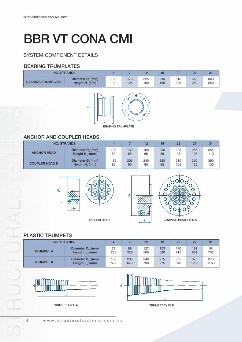
The type of stressing anchorage used may vary depending on the application, size and number of anchorages required, type of tendon sheathing, project location and availability of components. The tables below provide performance and dimensional data for
two typical anchorages. Several other BBR anchorage configurations are also available and there may be some variations in dimensions to those shown. The designer should check with Structural Systems for full and current technical information on the preferred anchorage type.
STRESSING ANCHORAGE TYPE M1 - ANCHORAGE CASTING WITH P.E. TRUMPET (LIVE END)
STRAND SIzE TYPE M1 ANCHORAGE DETAILS
12.7mm / 12.9mmAnchorage unit
Maximum no. Strands7057
120512
190519
310531
--
420542
610561
15.2mm / 15.7mmAnchorage unit
Maxiumum no. Strands4064
7067
120612
190619
220622
310631
420642
dimensions (mm)
A x ABc
inside dia. doutside dia. E
Anchor nom. dia. Fnom. Height G
165155100775512055
215345851107715055
2654151001399219065
33548511617911224080
35055012519311735080
395605145223137290100
460725175265157350120
Notes: • Local zone and general zone anchorage reinforcement is normally required for all unit types and details are usually determined by the designer to suit the specific application. • unless otherwise specified by the designer, SSL Multi-strand tendons will normally be supplied with type M1 stressing anchorages. • tendon grouting is achieved via 19mm poly pipe inlets at all anchorage ends and at intermediate venting points.
STRESSING ANCHORAGE TYPE M3 - FABRICATED PLATE ANCHORAGE (LIVE END)
STRAND SIzE TYPE M3 ANCHORAGE DETAILS 12.7mm / 12.9mm Anchorage unit 705 1205 1905 3105 - 4205 6105 - Maximum no. Strands 7 12 19 31 - 42 61 -
15.2mm / 15.7mm Anchorage unit 406 706 1206 1906 2206 3106 4206 5506 Maximum no. Strands 4 7 12 19 22 31 42 55
dimensions A x A 175 220 270 345 375 440 600 600 (mm) B 220 435 545 785 820 910 1230 1400 c 20 30 40 55 60 70 100 120 outside dia. d 90 115 140 195 210 232 275 325 outside dia. E 55 75 90 110 115 140 160 160
Notes: • Local zone and general zone anchorage reinforcement is normally required for all unit types and details are usually determined by the Designer to suit the specific application. • Unless otherwise specified by the Designer, multi-strand tendons will normally be supplied with Type M1 stressing anchorages. • Tendon grouting is achieved via 19mm poly pipe inlets at all anchorages and at intermediate venting points.
ANCHORAGE TYPE M1
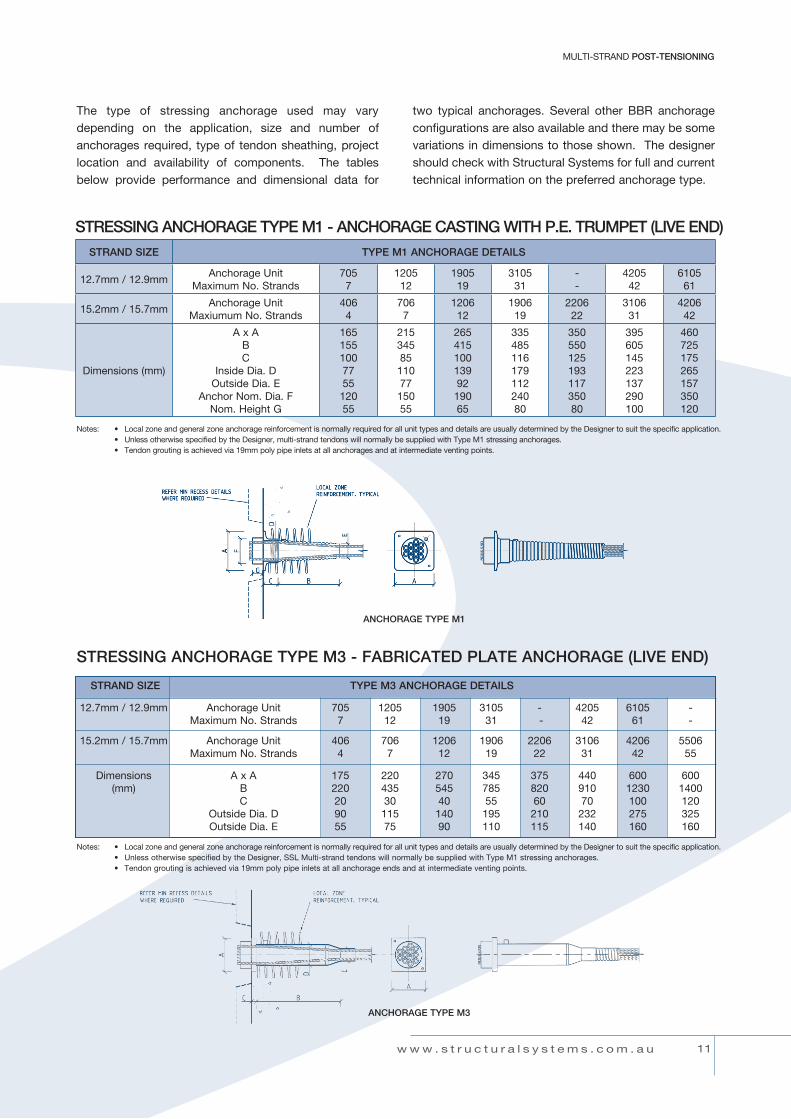
Notes: • Local zone and general zone anchorage reinforcement is normally required for all unit types and details are usually determined by the designer to suit the specific application
• Swage type dead end anchorages recommended for tendon units 3105/1906 and larger
dEAd End AncHorAGES - BuLB tYPE & SWAGE tYPE
STRAND SIzE ANCHORAGE UNIT BULB TYPE ANCHORAGE (mm) SWAGE TYPE ANCHORAGE (mm)
A B C D E F
12.7mm and 12.9mm 705 175 150 600 150 150 250 1205 300 250 1000 200 200 350 1905 375 300 1000 250 250 500 3105 450 425 1100 350 300 650 4205 600 450 1100 450 375 850 6105 700 550 1200 700 450 1000 15.2mm and 15.7mm 406 150 150 600 150 150 250 706 200 170 600 200 200 350 1206 350 300 1000 250 250 500 1906 450 350 1000 300 300 500 2206 500 350 1000 300 300 500 3106 550 475 1100 350 350 650 4206 700 550 1200 400 350 850 5506 800 600 1200 550 475 1000
1 2
PrEStrESSinG TECHNOLOGY
w w w . s t r u c t u r a l s y s t e m s . c o m . a u
MULTI-STRAND poST-TENSIoNING
BULB TyPE DEAD END SwAGE TyPE DEAD END
Transfer beams in buildings
note: For swage type, strand length ‘F’ shall be debonded (using grease or similar).

1 3
MuLti-StrAnd POST-TENSIONING
w w w . s t r u c t u r a l s y s t e m s . c o m . a u
couPLinG AncHorAGE - tYPE K
STRAND SIzE TYPE K COUPLING ANCHORAGE DETAILS
12.7mm / 12.9mm Anchorage unit 705 1205 1905 3105 - - - Maximum no. Strands 7 12 19 31 - - -
15.2mm / 15.7mm Anchorage unit 406 706 1206 1906 2206 3106 4206 Maximum no. Strands 4 7 12 19 22 31 42
diameter (mm) n 168 208 258 328 328 405 460 trumpet length (mm) P (approx) 550 650 700 900 950 1100 1200
Notes: • Unless otherwise specified by the Designer, multi-strand coupling anchorages will normally be supplied as Type K
• Refer to SSL for details and availability of larger K type coupler units
couPLinG AncHorAGE - tYPE c
STRAND SIzE TYPE C COUPLING ANCHORAGE DETAILS
12.7mm / 12.9mm Anchorage unit 705 1205 1905 3105 - 4205 6105 - Maximum no. Strands 7 12 19 31 - 42 61 -
dimensions (mm) Q 108 108 108 108 - 148 refer - r 170 200 230 340 - 385 to - S 550 650 740 1140 - 1320 SSL -
15.2mm / 15.7mm Anchorage unit 406 706 1206 1906 2206 3106 4206 5506 Maximum no. Strands 4 7 12 19 22 31 42 55
dimensions (mm) Q 125 125 125 125 125 145 refer refer r 160 200 230 270 300 350 to to S 520 630 730 860 930 1090 SSL SSL
Notes: • Unless otherwise specified by the Designer, SSL Multi-strand Coupling Anchorages will normally be supplied as Type K
• Refer to SSL for details and availability of larger C type coupler units

1 4
PrEStrESSinG TECHNOLOGY
w w w . s t r u c t u r a l s y s t e m s . c o m . a u
SPAcE rEQuirEMEntS For StrESSinG JAcKS
STRAND SIzE SPACE REqUIREMENTS
12.7mm / 12.9mm tendon unit 705 1205 1905 3105 - 4205 6105 -
15.2mm / 15.7mm tendon unit 406 706 1206 1906 2206 3106 4206 5506
Jack unit cc 110 cc 200 cc 300 cc 600 cc 600 cc 630 cc 1000 cc 1200 dimensions (mm) A 710 750 810 1200 1200 1000 1130 1300 B 1400 1500 1600 2400 2400 2000 2300 2600 c 250 300 330 500 500 600 600 600 E 200 230 260 400 400 500 420 450 F 595 620 675 1100 1100 950 950 1050
Notes: • Details based on jacks having 200mm working stroke. Alternative jacks may be available and/or more suitable. Contact SSL for further details
• check jack size and availability with your local SSL office
StrESSinG AncHorAGE rEcESS dEtAiLS
STRAND SIzE RECESS DETAILS
12.7mm / 12.9 mm tendon unit 705 1205 1905 3105 - 4205 6105 -
15.2mm / 15.7mm tendon unit 406 706 1206 1906 2206 3106 4206 5506
dimensions (mm) F x F 230 270 340 420 420 460 560 650 G 140 140 150 165 165 185 200 225 H x H 310 370 400 510 510 560 660 750
Notes: • Depth G achieves 50mm cover to trimmed strand ends. • Alternative or smaller recesses may be possible depending on actual conditions and jack used. Refer to your local Structural Systems office.
MULTI-STRAND poST-TENSIoNING
1 5
MuLti-StrAnd POST-TENSIONING
w w w . s t r u c t u r a l s y s t e m s . c o m . a u
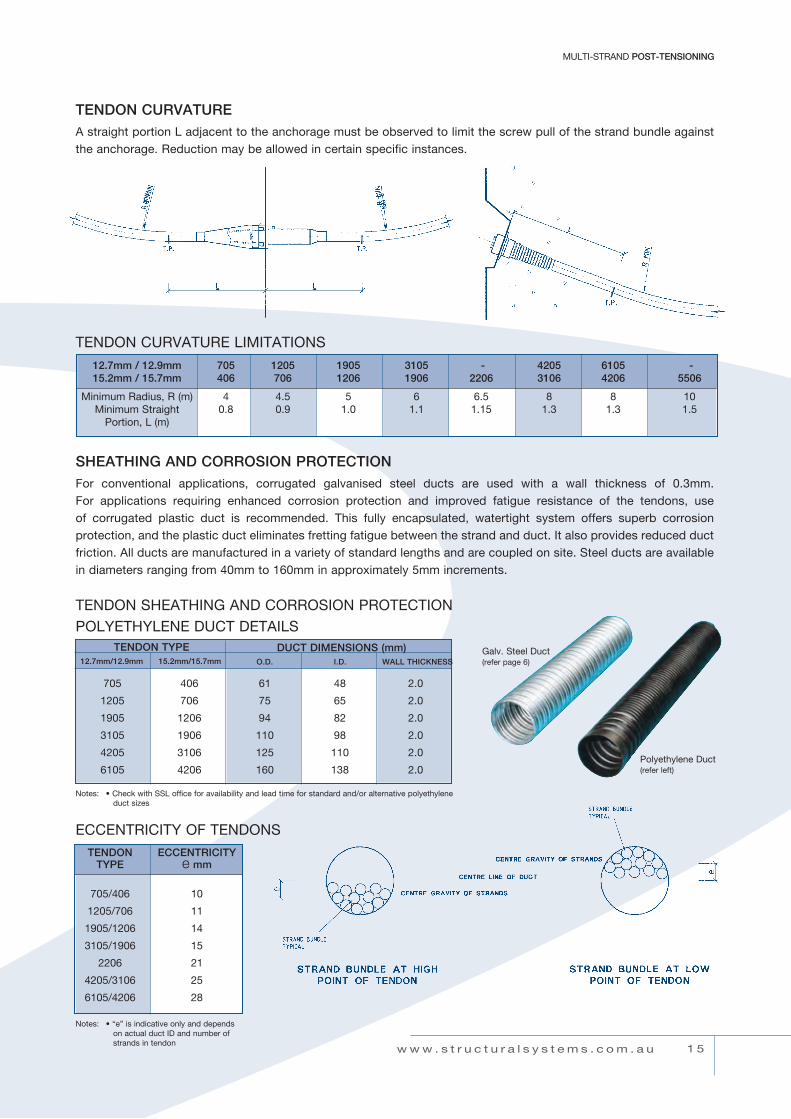
TENDON CURVATUREA straight portion L adjacent to the anchorage must be observed to limit the screw pull of the strand bundle against the anchorage. Reduction may be allowed in certain specific instances.
TENDON ECCENTRICITY TYPE e mm
705/406 10
1205/706 11
1905/1206 14
3105/1906 15
2206 21
4205/3106 25
6105/4206 28
SHEATHING AND CORROSION PROTECTIONFor conventional applications, corrugated galvanised steel ducts are used with a wall thickness of 0.3mm. For applications requiring enhanced corrosion protection and improved fatigue resistance of the tendons, use of corrugated plastic duct is recommended. This fully encapsulated, watertight system offers superb corrosion protection, and the plastic duct eliminates fretting fatigue between the strand and duct. It also provides reduced duct friction. All ducts are manufactured in a variety of standard lengths and are coupled on site. Steel ducts are available indiametersrangingfrom40mmto160mminapproximately5mmincrements.
Notes: • “e” is indicative only and depends on actual duct id and number of strands in tendon
tEndon SHEAtHinG And corroSion ProtEction
PoLYEtHYLEnE duct dEtAiLS
EccEntricitY oF tEndonS
tEndon curVAturE LiMitAtionS
12.7mm / 12.9mm 705 1205 1905 3105 - 4205 6105 - 15.2mm / 15.7mm 406 706 1206 1906 2206 3106 4206 5506
Minimum radius, r (m) 4 4.5 5 6 6.5 8 8 10 Minimum Straight 0.8 0.9 1.0 1.1 1.15 1.3 1.3 1.5 Portion, L (m)
Notes: • Check with SSL office for availability and lead time for standard and/or alternative polyethylene duct sizes
TENDON TYPE12.7mm/12.9mm 15.2mm/15.7mm
DUCT DIMENSIONS (mm) O.D. I.D. WALL THICKNESS
705 406 61 48 2.0
1205 706 75 65 2.0
1905 1206 94 82 2.0
3105 1906 110 98 2.0
4205 3106 125 110 2.0
6105 4206 160 138 2.0
Galv. Steel duct(refer page 6)
Polyethylene duct(refer left)

1 6
PrEStrESSinG TECHNOLOGY
w w w . s t r u c t u r a l s y s t e m s . c o m . a u
MULTI-STRAND poST-TENSIoNING
The minimum required distance of the bearing plates to concrete edges and to adjacent anchorage bearing plates depends in general on: • the post-tensioning force to be transmitted • the concrete strength • the bearing plate dimensions • the reinforcing steel behind the bearing plate • structural requirements
ao = min. distance between axis of two anchoragesbo = min. distance from concrete edge to anchorage axisDsp = suggested outside diameter of reinforcing steel spiralsf’c = nominal concrete cylinder strength
Prestressing forces can usually be applied at 80% of nominal concrete cylinder strength.
MINIMUM DISTANCE FOR BEARING PLATES TO CONCRETE EDGES AND BETWEEN ADJACENT ANCHORAGES
Tung Chung Bridge - Hong Kong
MINIMUM ANCHORAGE SPACING AND EDGE DISTANCES
f’cMPa
DETAILSmm
12.7mm & 12.9mm STRAND UNITS 15.2mm & 15.7mm STRAND TENDON UNITS
705 1205 1905 3105 4205 406 706 1206 1906 2206 3106 4205
32ao 220 290 365 465 545 205 270 355 450 480 570 665bo 130 155 190 235 275 120 145 180 225 240 285 335
dsp 200 250 320 410 480 180 230 300 390 425 520 590
40ao 205 270 340 435 505 200 255 330 420 450 535 620bo 125 150 185 225 260 120 145 175 215 230 275 310
dsp 190 240 310 390 460 180 230 290 370 400 490 560
50ao 195 255 320 410 475 200 250 310 395 420 500 585bo 120 145 180 220 250 120 145 175 210 225 265 300
dsp 180 230 300 380 440 180 230 290 360 390 470 540
Notes: • the above details are provided as a guide only and designers should normally satisfy themselves by calculation that the adopted details are suitable for the actual application.
Mt Henry Bridge - Western Australia

1 7
SLAB POST-TENSIONING
w w w . s t r u c t u r a l s y s t e m s . c o m . a u
SLAB poST-TENSIoNINGDesigners, builders, owners and end users of buildings require more efficiencies today than ever before. The Structural Systems Slab Post-Tensioning System offers all the stakeholders in a building project many benefits including:
• Reduced structural depths• Greater clear spans• Design flexibility• Formwork versatility• Reduced construction costs• Enhanced construction speed• Improved durability• Minimum maintenance costs
The system is comprised of high-strength steel strands placed inside flat ducting, anchored at one end by deforming the strand and casting it into the concrete,
then at the other end by means of a steel anchorage casting and anchor block(s) with gripping wedges. After the concrete has reached a suitable transfer strength, the individual strands have a specified load applied by calibratedjacks.Theductisfilledwithawater/cementgrout mixture to ensure that the system is bonded and corrosion protection is maintained in service.
Applications for the Structural Systems Slab Post-Tensioning System include:
• Low to high rise residential and commercial buildings
• Industrial floor slabs on grade• Transfer floor structures• Car parks• water tank bases and walls• Transverse stressing of bridge decks
West India Quay - London
Al Nuaimiah Towers - Dubai

1 8
PrEStrESSinG TECHNOLOGY
w w w . s t r u c t u r a l s y s t e m s . c o m . a u
LIVE END ANCHORAGES
SLAB poST-TENSIoNING
DEAD-END ANCHORAGES
BULB-TyPE SwAGE-TyPE
grout tube
grout tubebulbed strand ends
swaged strand endsspacer plate(not always required)
swage plate
strands
duct
anchorage casting
anchorage block
duct
grout tube
duct
notes:
• Similar non-reusable recess- formers are used at angled edges
• Standard flat duct is produced from 0.4mm galvanised steel sheet
StrESSinG AncHorAGE (LiVE EndS)
BULB-TYPE DEAD-END ANCHORAGE SWAGE-TYPE DEAD-END ANCHORAGE STRAND SIzE TENDON UNIT DIMENSIONS (mm) DIMENSIONS (mm) A B C D E F
105 75 50 600 100 75 100 12.7mm 205 135 50 600 125 75 150 and 305 230 50 600 200 75 350 12.9mm 405 270 50 600 250 75 500 505 350 50 600 300 75 500 605 400 50 750 350 75 600
106 75 50 750 125 75 100 15.2mm 206 135 50 750 150 75 250 and 306 230 50 750 225 75 450 15.7mm 406 270 50 750 300 75 600 506 350 50 750 350 75 600
STRAND SIzE TENDON UNIT No. STRANDS
ANCHORAGE CASTING
RECESS FORMERFLAT DUCT SIzE
mmAmm
Bmm
Cmm
Dmm
E1mm
E2mm
F1mm
F2mm
12.7 mmand
12.9 mm
205305505605
23
4 or 56
155150215270
135150220265
67757979
100100100100
150180265265
150180315315
1001008080
100100100100
43 x 1943 x 1970 x 1990 x 19
15.2 mmand
15.7 mm
206406506
23 or 4
5
155215270
135220265
677979
100100100
150265265
150315315
1008080
100100100
43 x 1970 x 1990 x 19
grout tube
dead end plate
duct
Notes: • Tendon units 205, 605, and 206 are supplied with individual barrel anchorages in lieu of anchorage blocks. • Grout tubes are 13mm id or 19mm id polyethylene pipe supplied to each end of tendon. Additional intermediate vents can also be supplied (designer to specify requirements). • All sizes are nominal. Some dimensions have been rounded up for normal space, detailing and tolerance requirements.
wedge grips
grout tube duct
anchorage casting
wedge
strand
barrel
1 9
SLAB POST-TENSIONING
w w w . s t r u c t u r a l s y s t e m s . c o m . a u
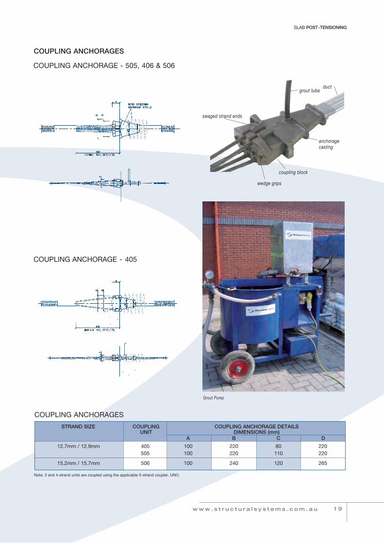
wedge grips
grout tube
anchorage casting
coupling block
couPLinG AncHorAGE - 505, 406 & 506
couPLinG AncHorAGE - 405
COUPLING ANCHORAGES
couPLinG AncHorAGES
STRAND SIzE COUPLING COUPLING ANCHORAGE DETAILS UNIT DIMENSIONS (mm) A B C D
12.7mm / 12.9mm 405 100 220 80 220 505 100 220 110 220
15.2mm / 15.7mm 506 100 240 120 265
swaged strand ends
note: 3 and 4-strand units are coupled using the applicable 5-strand coupler, uno.
Grout Pump
duct

2 0
PrEStrESSinG TECHNOLOGY
w w w . s t r u c t u r a l s y s t e m s . c o m . a u
AncHorAGE rEinForcEMEnt – SLAB SYStEM
Notes: • Reinforcement size 10dia, grade 500MPa to AS/NZS 4671 or grade 460 to BS4449. • fcp = min required air-cured concrete cylinder strength at anchorage at time of stressing. • Details shown are generally satisfactory for most standard situations, however designers should satisfy themselves of the adequacy of local zone anchorage
reinforcement for specific situations.
SLAB poST-TENSIoNING
SPirAL tYPE
StrAnd At tEndon HiGH Point StrAnd At tEndon LoW Point
2x2 LiGAturE2x1 LiGAturE SiMiLAr
2x4 LiGAturE
SuGGEStEd ALLoWAncES – StrAnd oFFSEtS For 19mm FLAt duct STRAND SIzE A B e
12.7mm / 12.9mm 7mm 12mm 2.5mm 15.2mm / 15.7mm 8mm 11mm 1.5mm
TENDON UNIT
No. OF STRANDS
SPIRAL TYPE LIGATURE TYPEfcp
MPaAmm
Bmm
NNo.
Cmm
Dmm
NNo.
205305505605206406506
23
4 or 562
3 or 45
9010010011090110110
200260260300200300300
4457477
200200200200200200200
100100130150110130150
2 x 12 x 12 x 22 x 42 x 22 x 22 x 4
17172225172225

2 1
SLAB POST-TENSIONING
JAcKinG cLEArAncES STRAND SIzE A B C D E mm mm mm mm mm
12.7mm / 12.9mm 500 900 750 450 70 15.2mm / 15.7mm 600 900 850 450 70
w w w . s t r u c t u r a l s y s t e m s . c o m . a u
JAcKinG cLEArAncES
douBLE rAM JAcK SinGLE rAM JAcK
intErnAL StrESSinG PocKEtS
Stressing Pocket
Notes: • Internal Stressing Pockets are used where standard edge stressng is impractical, subject to design check. • Details shown provide typical pocket spacing requirements. Actual details may vary.

2 2
PrEStrESSinG TECHNOLOGY
w w w . s t r u c t u r a l s y s t e m s . c o m . a u
Post-tensioning provides many benefits to a wide range of suspended structures. these benefits include:
• Reduced construction cost• Faster construction• Water resistant properties• Early formwork stripping• Floor to floor height reduction• Reduced foundation load• Improved deflection control• Greater column free areas
Many types of suspended slab structures typically realise the benefits of post tensioning, such as:
• Carparks• Apartment buildings• Commercial office space• Retail centres• Vertical load transfer structures• Hospitals• Storage facilities• Public buildings such as stadiums, exhibition
centres, schools and institutional facilities
different formwork systems are compatible with post-tensioning, namely:
• Conventional plywood systems• Permanent metal deck systems• Ribbed slabs• Precast systems
Structural Systems has many years of experience in the design and installation of post-tensioned suspended slabs and can bring measurable benefits to your project.
SLAB PoSt-tEnSioninG APPLicAtionS - suspended slabs
Peppers Pier Resort - Queensland
Wollongong Links Project - NSW

2 3
SLAB POST-TENSIONING
w w w . s t r u c t u r a l s y s t e m s . c o m . a u
it is important that the design requirements are achieved on site. Good engineering notation can greatly assist in achieving this, with particular attention to the following;
• The system. State that the design is based on the Structural Systems SLAB post-tensioning system. this ensures that a fully tested and code compliant system will be installed.
• Concrete. nominate the 28 day characteristic compressive strength and shrinkage characteristics required. Some projects may have additional requirements.
• Concrete strength at Transfer fcp. this is the minimum compressive strength that is required prior to fully stressing the tendons. concrete testing of site and air cured specimens should be carried out to ensure this strength has been achieved prior to application of the final stressing.
• Tendons. clearly indicate the type and location of anchorages and number of strands in each tendon. check that stressing access is possible at live ends.
• profiling. High and low points should be nominated. Full tendon profiles can then be determined on installation shop drawings. Profiles are usually parabolic.
• stressing procedure. A two stage stressing procedure is usually specified. initial or 25% load is applied at 24 hours after the slab pour, and final or 100% load is applied when the concrete transfer strength is released.
• Grout. A water/cement ratio of not more than 0.45 is usually sufficient to ensure adequate grouting and strength.
BAndEd SLAB FLAt SLAB FLAt PLAtE
the design of post-tensioned suspended slabs requires sound engineering consideration in order to maximize the benefits for all stakeholders in a project.
Structural Systems can offer design input from initial advice to fully detailed design for construction drawings. typical post-tensioned floor configuration and details are:
dESiGn oF PoSt-tEnSionEd - suspended slabs
dEFinitionS Lb = Band SpanLs = Slab SpanL = design Span (Greater of L1 & L2)note: For Slab End Spans, Add 15-20% to Slab thickness from charts
t = internal Slab thicknessd = overall Band depthBw = Suggested Band Width Approx. (suit formwork)P = overall drop Panel depth (1.8xt)
tYPicAL dESiGn LoAdS LL = 5kPa, AdL = 1kPa LL = 4kPa, AdL = 1kPa LL = 3kPa, AdL = 1kPa LL = 2.5kPa, AdL = 0.5kPa
SPEciFYinG PoSt-tEnSioninG
2 4
PrEStrESSinG TECHNOLOGY
w w w . s t r u c t u r a l s y s t e m s . c o m . a u
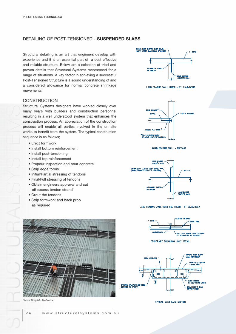
Structural detailing is an art that engineers develop with experience and it is an essential part of a cost effective and reliable structure. Below are a selection of tried and proven details that Structural Systems recommend for a range of situations. A key factor in achieving a successful Post-tensioned Structure is a sound understanding of and a considered allowance for normal concrete shrinkage movements.
conStructionStructural Systems designers have worked closely over many years with builders and construction personnel resulting in a well understood system that enhances the construction process. An appreciation of the construction process will enable all parties involved in the on site works to benefit from the system. the typical construction sequence is as follows;
• Erect formwork• install bottom reinforcement• install post-tensioning• install top reinforcement• Prepour inspection and pour concrete• Strip edge forms• Initial/Partial stressing of tendons• Final/Full stressing of tendons• obtain engineers approval and cut
off excess tendon strand• Grout the tendons• Strip formwork and back prop as required
dEtAiLinG oF PoSt-tEnSionEd - suspended slabs
Cabrini Hospital - Melbourne
2 5
SLAB POST-TENSIONING
w w w . s t r u c t u r a l s y s t e m s . c o m . a u
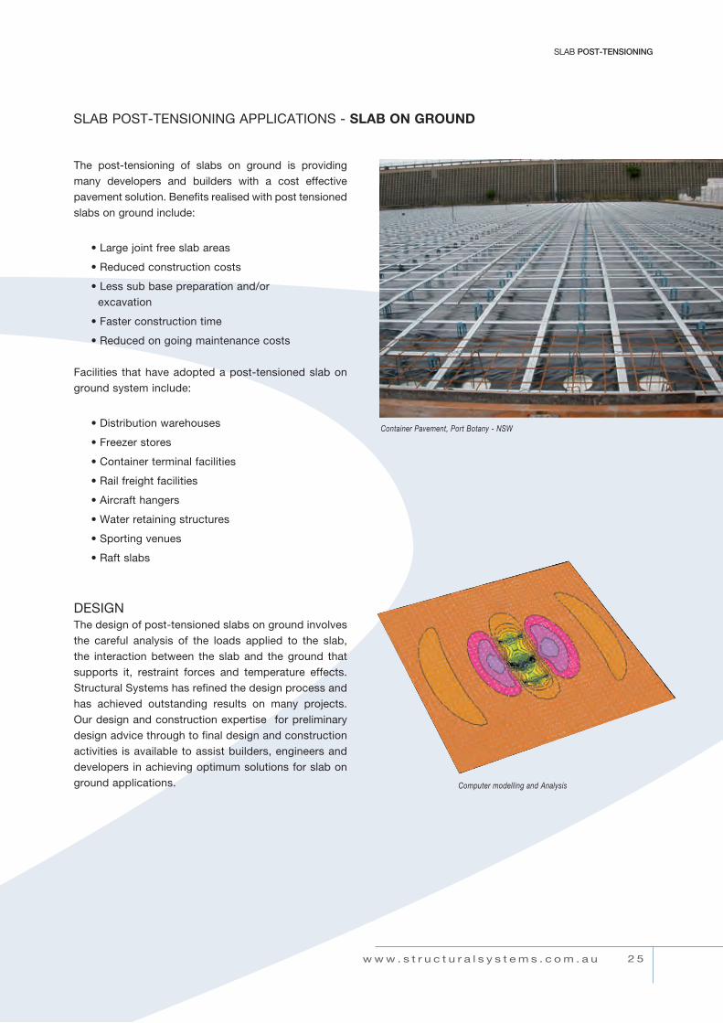
the post-tensioning of slabs on ground is providing many developers and builders with a cost effective pavement solution. Benefits realised with post tensioned slabs on ground include:
• Large joint free slab areas
• reduced construction costs
• Less sub base preparation and/or excavation
• Faster construction time
• reduced on going maintenance costs
Facilities that have adopted a post-tensioned slab on ground system include:
• distribution warehouses
• Freezer stores
• container terminal facilities
• rail freight facilities
• Aircraft hangers
• Water retaining structures
• Sporting venues
• raft slabs
dESiGnthe design of post-tensioned slabs on ground involves the careful analysis of the loads applied to the slab, the interaction between the slab and the ground that supports it, restraint forces and temperature effects. Structural Systems has refined the design process and has achieved outstanding results on many projects. our design and construction expertise for preliminary design advice through to final design and construction activities is available to assist builders, engineers and developers in achieving optimum solutions for slab on ground applications.
SLAB PoSt-tEnSioninG APPLicAtionS - slab on Ground
Container Pavement, Port Botany - NSW
Computer modelling and Analysis

2 6
PrEStrESSinG TECHNOLOGY
w w w . s t r u c t u r a l s y s t e m s . c o m . a u
Points to consider in the design process include:
design Loads and Load configurations
thermal Effects daily ambient temperature variations give rise to temperature gradient stresses through the slab depth which need to be accounted for in the design. typical gradients of 0.02 ºc/mm and 0.04 ºc/mm are often used for internal and external slabs respectively causing bottom fibre tensile stresses that are additional to the load stresses.
Sub-grade Frictionnormal elastic and shrinkage movements give rise to frictional restraint stresses between the slab and the prepared subgrade. the typical design friction coefficient for concrete laid on a plastic membrane over clean sand bedding is around 0.5 to 0.6.
Sub-base Parameters A typical slab design will include the analysis of the slab supported by the ground sub-base. Modelling of the sub-base requires geotechnical data such as cBr, and/or the modulus of sub-grade reaction.
dESiGn oF PoSt-tEnSionEd slab on Ground
b) dESiGn WHEEL / AxLE dEtAiLS
a) tYPicAL dESiGn rAcKinG LAYout
dAtA - design Axle load “P” - Wheel Spacing “W” (2 or 4 wheels etc.) - Axle Load repetitions - Wheel contact Stress
Warehouse floor construction using laser screeds Raft Foundation - The Moorings, Western Australia
Typical racking storage

2 7
SLAB POST-TENSIONING
Good detailing of post-tensioned slabs on ground is vital in achieving a successful and relatively crack free slab.
the following diagrams indicate key details typicallyrecommended by Structural Systems:
dESiGn oF PoSt-tEnSionEd slab on Ground
conStructionStructural Systems design and construction experience is based on being the leader in the field of post-tensioned slabs on ground. the combination of innovative design and expedient site practices ensures that the construction phase is a seamless operation. the main items to consider for the construction phase are;
Pour SizeA pour size of between 1500m2 and 2000m2 should typically be considered and planned.
Pour Sequence the sequence of slab pours and their respective stressing requirements should be optimized to ensure the best programme outcome.
curing and Weather ProtectionWith large pours the slab is initially susceptible to shrinkage effects hence it is important to cure and protect the slab from extreme conditions such as heat, high evaporation or extreme cold. the construction of warehouse roofs prior to pouring slabs is a typical technique adopted to provide some protection.
tYPicAL WArEHouSE PLAn
Note: • As a guide, allow for total slab edge & M.J. movements of approximately 0.5mm per metre length of slab (e.g for 60m long slab, each edge moves approx 15mm over the normal life of the slab),
Column blockout detail
w w w . s t r u c t u r a l s y s t e m s . c o m . a u

2 8
PrEStrESSinG TECHNOLOGY
w w w . s t r u c t u r a l s y s t e m s . c o m . a u
MULTI-WIRE poST-TENSIoNINGThe BBR SSL Multi-wire System is more compact than the multi-strand system and is often preferred for coupled cables in incrementally launched bridges, and is ideally suited where cables are to be prefabricated and where restressing or destressing is required.
The multi-wire tendon is composed of a bundle of 7mm dia. wires (plain or galvanised). Each individual wire is fixed in the anchorage with a multi-wire button head, which is cold-formed onto the wire by means of special machines.
• Each wire is mechanically fixed in the anchor head and reaches the full rupture load of the prestressing steel without any slippage. therefore the wire bundle can sustain the maximum ultimate load.
• the prestressing force is transmitted to the concrete under precisely known conditions without any risk of slippage of the prestressing steel.
• Monitoring of the prestressing force and if necessary restressing can be carried out reliably and economically. if required, the tendon can also be completely destressed.
• the anchorage resists with a high degree of safety dynamic loads and also exceptional effects such as shock loads.
typical applications include:
• coupled cables in incremtally launched bridges.
• cable stay applications.
• restressable tendons.
• Heavy lifting and lowering cables.
• restressable ground anchors.
Centrepoint Tower - Sydney
Narrows Bridge Duplication - Western Australia

2 9
MuLti-WirE POST-TENSIONING
w w w . s t r u c t u r a l s y s t e m s . c o m . a u
STRESSING JACK TYPE NP 60 NP 100 NP 150 NP 200 NP 250 NP 300 GP 500 GP 800
Maximum Jacking Force kn 620 1030 1545 2060 2575 3090 5150 8000 Jack diameter mm 160 205 250 290 315 350 560 660 Stroke mm 100 100 100 100 100 100 400 400 Weight kg 28 50 83 117 147 196 1260 2000 clearance requirement ‘A’ mm 1700 1700 1700 2000 2000 2000 2500 2500
PrEStrESSinG JAcKS
Grouting of Ducts SSL has developed grouting methods utilising special colloidal mixers which result in an optimal grouting of the tendon ducts.
Prestressing EquipmentThe prestressing equipment consist of a hydraulic jack, trestle and pull-rod, which is connected to the stressing anchorage. For tendon elongations greater than the stroke of the jack, the pull-rod is temporarily anchored with a lock-nut and the jack is recycled.
The prestressing force can be measured with an accuracy of 2% by using calibrated 150mm face bourdon typepressure gauges.
Standard TendonsThe anchoring method allows the production of post-tensioning tendons with any number of single wires and therefore with any given magnitude of prestressing force. The most commonly used wire diameter is 7 millimetres.
with the following range of STANDARD TENDONS, all prestressing requirements occurring in the construction of bridges, buildings and other structures can be met. For special applications, eg; nuclear vessels, tendons up to15,000kNultimatecapacityareavailable.
StAndArd SSL - BBr WirE tEndonS NUMBER OF WIRES, DIA. 7mm 8 19 31 42 55 61 85 109 121 143
Minimum Breaking Load (rm = 1670 MPa) kn 514 1222 1993 2701 3537 3922 5466 7009 7780 9195 Stressing force at 0.8 x MBL kn 412 977 1595 2160 2829 3138 4372 5607 6224 7356 Stressing force at 0.75 x MBL kn 386 916 1495 2025 2652 2942 4099 5257 5835 6896
tendon nominal cross sectional area mm2 308 731 1194 1617 2118 2349 3273 4197 4659 5506
Weight of tendon wire kg/m 2.42 5.74 9.36 12.68 16.61 18.42 25.67 32.92 36.54 43.19 duct i.d. mm 35 50 55 65 80 85 100 110 120 130
Notes: • Check jack size and availability with your local SSL office
Notes: • Rm = Characteristic Tensile Strength to AS 4672 and/or BS 5896

3 0
PrEStrESSinG TECHNOLOGY
w w w . s t r u c t u r a l s y s t e m s . c o m . a u
MULTI-WIRE poST-TENSIoNING
SPECIAL APPLICATION ANCHORAGESDetails of Anchorages for various special applications are also available on request .
STRESSING ANCHORAGE TYPE L
STRESSING ANCHORAGE TYPE A
FIXED ANCHORAGE TYPE S
FIXED COUPLING TYPE LK
MOVABLE COUPLING TYPE LK 1
NUMBER OF WIRES 8 12 19 31 42 55 61 85 109 121 143dia. 7mm
Anchor e mm 25 27 36 43 49 56 67 78 85 140 145
Elongation, max f mm 200 200 200 200 200 250 250 350 350 400 400
trumpet length g mm 170 185 200 280 310 335 360 390 420 450 500
diameter h mm 37 49 59 76 87 97 105 120 135 145 160
Bearing plate i mm 140 170 200 235 270 300 330 380 430 480 500
thickness it mm 16 20 25 30 40 45 50 60 70 80 80
NUMBER OF WIRES 8 12 19 31 42 55 61 85 109 121 143dia. 7mm
Fan length k mm 460 550 660 830 880 960 1010 1060 1180 1220 1260
Anchor plate, sq l mm 120 160 200 250 280 320 350 400 450 470 520
rectangular l mm 70 90 120 140 160 180 200 240 260 280 300
w mm 200 270 340 420 500 560 600 660 760 790 900
NUMBER OF WIRES 8 12 19 31 42 55 61 85 109 121 143 dia. 7mm
Anchor amm 63 74 91 108 123 135 156 180 205 240 245
TrumpetLength bmm 250 250 250 280 300 300 300 340 360 400 500
Diameter cmm 70 88 102 123 138 153 171 193 219 240 252
BearingPlate dmm 140 170 200 245 285 315 345 400 450 500 520
Thickness dtmm 14 16 20 25 30 35 40 50 60 70 70
NUMBER OF WIRES 8 12 19 31 42 55 61 85 109 121 143dia. 7mm
trumpet length q mm 230 260 290 350 410 430 470 570 630 680 730
diameter r mm 70 88 102 123 138 153 171 193 219 250 260
NUMBER OF WIRES 8 12 19 31 42 55 61 85 109 121 143dia. 7mm
Trumpet length min smm 600 620 670 750 810 880 950 1080115012201260
Diameter tmm 70 88 102 123 138 153 171 193 219 250 260

3 1
BAr POST-TENSIONING
w w w . s t r u c t u r a l s y s t e m s . c o m . a u
BAR poST-TENSIoNING
Corrosion ProtectionAll bars and fittings must receive protection when installed under permanent conditions. in normal concrete construction the use of galvanised duct, injected with grout, provides excellent protection. Anchorage recesses must also be filled with cement mortar to protect these end zones.
When bars are used in an exposed environment then other corrosion protection systems are available for the bar and fittings. these include:
• greased and sheathing bar• denso wrapping• epoxy painting
Temporary Bar AnchorsAnchors used in a temporary environment may be used without protection apart from grout required to the bond length.
Permanent Bar Anchorsthese anchors require installation into corrugated polyethylene sheathing or galvanised duct similar to strand anchors to provide multiple levels of protection. this is accomplished by the internal grout and sheathing barrier.
Macalloy Bar Systems are ideal for the economic application of post-tensioning forces on relatively short tendons. through the use of threaded connections and anchorages they are simple to use and lend themselves to many applications.
the robust coarse thread (ct) on the Macalloy bar ensures rapid and reliable assembly. this is particularly suitable for onsite use and reuse.
Typical ApplicationsBuildings
• Prestressed Beams and columns • Precast connections • temporary Bracing
Bridges • Stay cables and Hangers • Precast Segments • Strengthening (timber & Steel Bridges)
• tension Piles and caissons
Wharves & Jetties
• Stressed deck Planks • tie Backs
Soil and/or rock Anchors
• Permanent and temporary Anchors • uplift Anchors (dam & Foundation) • tunnel roof Bolting • Soil nails and rock Bolts • Slope Stabilisation • crane and tower Bases
Specialist Engineering • Heavy Lifting • Formwork ties and Hangers • Frame ties • Pile testing • Architectural ties and Stays
Characteristic PropertiesMacalloy Bar Properties are listed in the following tables.
Macalloy 1030 Bar Components
Bearing Plate
Nut Bar
WasherCoupler
3 2
PrEStrESSinG TECHNOLOGY
w w w . s t r u c t u r a l s y s t e m s . c o m . a u
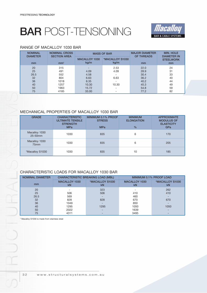
BAR poST-TENSIoNINGrAnGE oF MAcALLoY 1030 BAr
GRADE CHARACTERISTIC ULTIMATE TENSILE
STRENGTHMPa
MINIMUM 0.1% PROOF STRESS
MPa
MINIMUM ELONGATION
%
APPROXIMATE MODULUS OF ELASTICITY
GPa
Macalloy 103025-50mm
1030 835 6 170
Macalloy 103075mm
1030 835 6 205
*Macalloy S1030 1030 835 10 185
MEcHAnicAL ProPErtiES oF MAcALLoY 1030 BAr
NOMINAL DIAMETER
mm
CHARACTERISTIC BREAKING LOAD (MBL) MINIMUM 0.1% PROOF LOAD
MACALLOY 1030kN
*MACALLOY S1030kN
MACALLOY 1030kN
*MACALLOY S1030kN
2025
26.53236405075
-5065698281049129520224311
323506
-828
-1295
--
-410460670850105016393495
262410
-670
-1050
--
cHArActEriStic LoAdS For MAcALLoY 1030 BAr
* Macalloy S1030 is made from stainless steel
NOMINAL DIAMETER
mm
NOMINAL CROSS SECTION AREA
mm2
MASS OF BAR MAJOR DIAMETER OF THREADS
mm
MIN. HOLE DIAMETER IN STEELWORK
mmMACALLOY 1030
kg/m*MACALLOY S1030
kg/m
2025
26.53236405075
3154915528041018125719634185
-4.094.586.638.3510.3015.7233.00
2.534.09
-6.63
-10.30
--
22.028.930.436.240.245.354.877.2
2431334044495982
3 3
BAr POST-TENSIONING
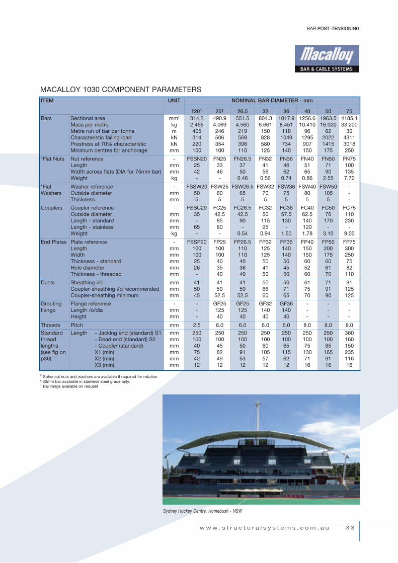
ITEM UNIT NOMINAL BAR DIAMETER - mm
†201 251 26.5 32 36 40 50 75Bars Sectional area
Mass per metreMetre run of bar per tonnecharacteristic failing loadPrestress at 70% characteristicMinimum centres for anchorage
mm2
kgmknknmm
314.22.466405314220100
490.94.069246506354100
551.54.560219569398110
804.36.661150828580125
1017.98.4511181049734140
1256.610.410
961295907150
1963.516.020
6220221415175
4185.433.200
3043113018250
*Flat nuts nut referenceLengthWidth across flats (diA for 75mm bar)Weight
-mmmmkg
FSSn202542-
Fn253346-
Fn26.53750
0.46
Fn324156
0.56
Fn364662
0.74
Fn405165
0.86
Fn507190
2.55
Fn751001357.70
*Flat Washers
Washer referenceoutside diameterthickness
-mmmm
FSSW20505
FSW25605
FSW26.5655
FSW32705
FSW36755
FSW40805
FSW501055
---
couplers coupler referenceoutside diameterLength - standardLength - stainlessWeight
-mmmmmmkg
FSSc2035-
65-
Fc2542.58580-
Fc26.542.590-
0.54
Fc325011595
0.94
Fc3657.5130
-1.50
Fc4062.51401201.78
Fc5076170
-3.10
Fc75110230
-9.00
End Plates Plate referenceLengthWidththickness - standardHole diameterthickness - threaded
-mmmmmmmmmm
FSSP201001002526-
FP25100100403540
FP26.5110110403640
FP32125125504150
FP36140140504550
FP40150150605260
FP50200175606170
FP753002507582110
ducts Sheathing i/dcoupler-sheathing i/d recommendedcoupler-sheathing minimum
mmmmmm
415045
4159
52.5
4159
52.5
506660
507165
617570
719190
91125125
Grouting flange
Flange referenceLength /o/diaHeight
-mmmm
---
GF2512540
GF2512540
GF3214040
GF3614040
---
---
---
threads Pitch mm 2.5 6.0 6.0 6.0 6.0 8.0 8.0 8.0Standard thread lengths (see fig on p30)
Length - Jacking end (standard) S1 - dead end (standard) S2 - coupler (standard) x1 (min) x2 (min) x3 (min)
mmmmmmmmmmmm
25010040754212
25010045824912
25010050915312
250100601055712
250100651156212
250100751307116
250100851659116
36016015023511616
MAcALLoY 1030 coMPonEnt PArAMEtErS
* Spherical nuts and washers are available if required for rotation.† 20mm bar available in stainless steel grade only.1 Bar range available on request
Sydney Hockey Centre, Homebush - NSW
w w w . s t r u c t u r a l s y s t e m s . c o m . a u

3 4
PrEStrESSinG TECHNOLOGY
w w w . s t r u c t u r a l s y s t e m s . c o m . a u
MAcALLoY 1030 SuGGEStEd MiLd StEEL End BLocK rEinForcEMEntnB: Helix and links must be used together with minimum 35 MPa concrete - see figure above
Notes: • A longitudinal length of rod may be used to attach the links but it is not required as part of the reinforcement • A more detailed explanation of the Macalloy Post Tensioning System is available in the Macalloy Design Data Handbook • There are many permutations possible to achieve satisfactory construction details, and advice is readily available from Structural Systems
otHEr MAcALLoY BAr SYStEMS ALSo AVAiLABLE
• Macalloy 460 carbon steel tendons• Macalloy S460 stainless steel tendons• Macalloy Guy Linking stainless steel bar tendons• Macalloy Guy Linking stainless steel cable tendons• Macalloy 17MHS Sheet piling ties
• Macalloy 500 reinforcing bars• Macalloy 500 tie bars• Macalloy 650 Stainless tie bars• Macalloy-tensoteci Galvanised cable tendons
MAcALLoY 1030 tYPicAL End BLocK ArrAnGEMEnt
MAcALLoY 1030 BAr End tHrEAd diMEnSionS
x1 = live endx2 = dead endx3 = length of bar past nut or thru’ threaded plate
S1 = live end threadS2 = dead end threadL = length over plates
MACALLOY DIAMETER
mm
HELIX LINKS
ROD DIAM.mm
I/Dmm
PITCHmm
TURNSNo.
ROD DIAM.mm
SPACINGmm
NUMBER
2526.53236405075
12121212121620
130130165195220250350
40404040405075
5567788
888881016
7070808080100100
3334446
3 5
Ground AncHor SYSTEMS
w w w . s t r u c t u r a l s y s t e m s . c o m . a u
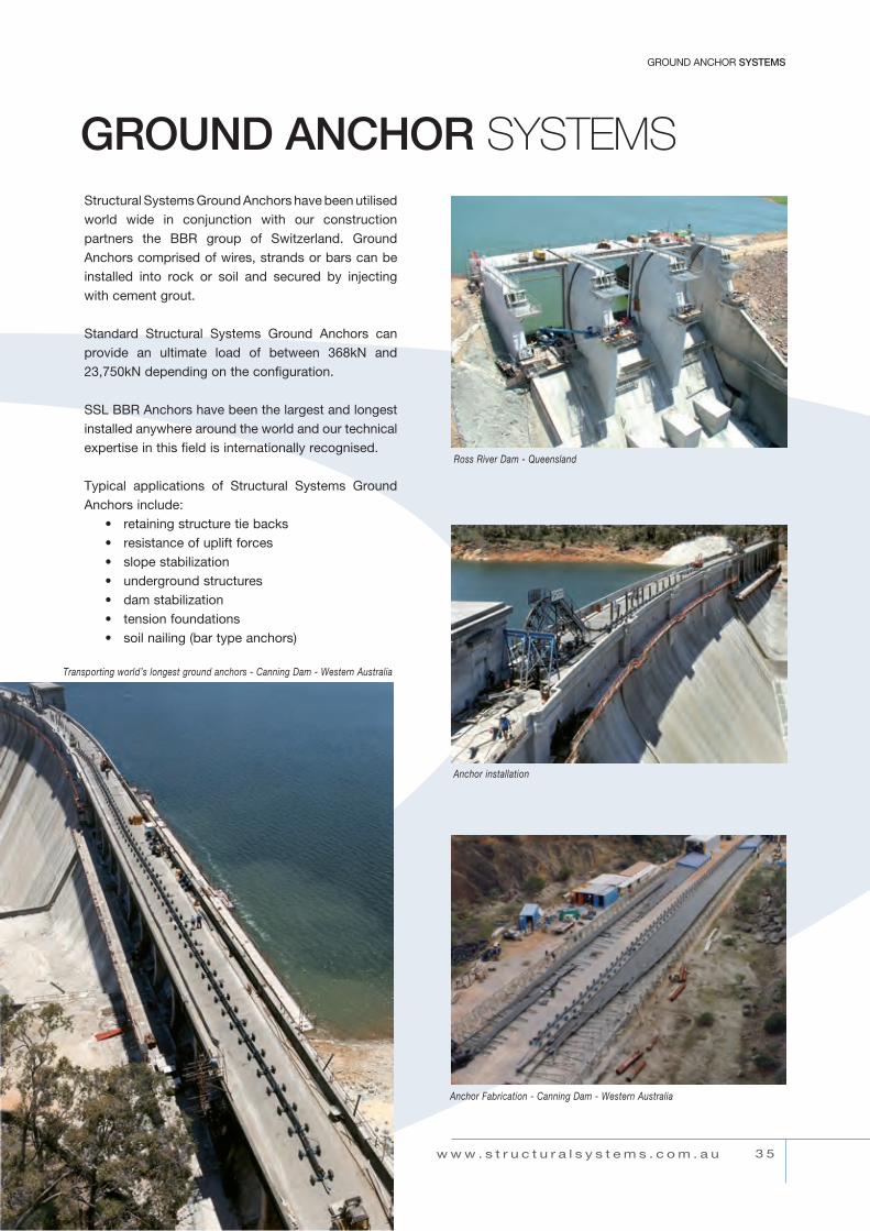
GROUND ANCHOR SySTEmSStructural Systems Ground Anchors have been utilised world wide in conjunction with our construction partners the BBr group of Switzerland. Ground Anchors comprised of wires, strands or bars can be installed into rock or soil and secured by injecting with cement grout.
Standard Structural Systems Ground Anchors can provide an ultimate load of between 368kn and 23,750kn depending on the configuration.
SSL BBr Anchors have been the largest and longest installed anywhere around the world and our technical expertise in this field is internationally recognised.
typical applications of Structural Systems Ground Anchors include: • retaining structure tie backs • resistance of uplift forces • slope stabilization • underground structures • dam stabilization • tension foundations • soil nailing (bar type anchors)
Transporting ground anchorsTransporting world’s longest ground anchors - Canning Dam - Western Australia
Anchor Fabrication - Canning Dam - Western Australia
Anchor installation
Ross River Dam - Queensland

3 6
PrEStrESSinG TECHNOLOGY
w w w . s t r u c t u r a l s y s t e m s . c o m . a u
GROUND ANCHOR SySTEmSStrAnd tYPE AncHorS

3 7
Ground AncHor SYSTEMS
w w w . s t r u c t u r a l s y s t e m s . c o m . a u
tYPicAL Ground AncHor tEndon conFiGurAtionS
Notes: • Strand tendons are based on MBL = 184kN (12.7mm strand) and MBL = 250kN (15.2mm strand) (Higher strand / anchor capacities available on request) • Details listed apply to typical applications and may vary to suit actual applications • Macalloy Bar tendons are more commonly used for short anchor lengths • Macalloy Bar anchor details exclude allowance for coupling of bars - refer SSL for details if required
TENDON STRAND / BAR SIzE
mm
MAXIMUM STRANDS PER UNIT
No.
MINIMUM BREAKING
LOAD
kN
BORE HOLE DIAMETER PERMANENT ANCHOR SHEATH SIzE ID / OD
BEARING PLATE SIzE
TYPICAL
mm
TEMPORARY ANCHORS
mm
PERMANENT ANCHORS
mm
CORRUGATED
mm
SMOOTH
mm
StrAnd
15.2mmor
15.7mm
247121922273142556591
500100017503000475055006750775010500137501625022750
7689102114165165178178229241254311
102127152178216216216216311311311356
50 / 6565 / 8580 / 100100 / 120125 / 165125 / 165125 / 165125 / 165210 / 230210 / 230210 / 230250 / 270
55 / 6367 / 7582 / 90
102 / 110150 / 160150 / 160150 / 160150 / 160225 / 235225 / 235225 / 235257 / 270
200 x 200 x 32200 x 200 x 36300 x 300 x 50350 x 350 x 60400 x 400 x 70450 x 450 x 80500 x 500 x 80500 x 500 x 90600 x 600 x 100700 x 700 x 120700 x 700 x 140900 x 900 x 160
91+ under development - refer SSL
StrAnd12.7mm
or12.9mm
247
3687361288
7689102
102127152
50 / 6565 / 8080 / 100
55 / 6367 / 7582 / 90
200 x 200 x 32200 x 200 x 36250 x 250 x 40
larger sizes on request - refer SSL
MAcALLoY BAr26.532405075
11111
569828129520224311
76102102127152
127152152175203
65 / 8080 / 10080 / 100100 / 127130 / 150
n/an/an/an/an/a
200 x 200 x 40250 x 250 x 50300 x 300 x 60300 x 300 x 60400 x 400 x 90

External prestressing was first used in the late 1920’sand has recently undergone a resurgence being used in bridges, both for new construction as well as strengthening of existing structures.
Features of External Prestressing
External prestressing is characterised by the following features:
• the prestressing tendons are placed on the outside of the physical cross section (mostly in concrete) of the structure.
• the forces exerted by the prestressing tendons are only transferred to the structure at the anchorages and at deflectors.
• no bond is present between the tendon and the structure, except at anchorage and deflector locations.
Advantages of External Prestressing
Compared to internal bonded post-tensioning the external prestressing has the following distinct advantages:
a) The application of external prestressing can be combined with a broad range of construction materials such as steel, timber, concrete, composite structures and plastic materials. This can considerably widen the scope of the post-tensioning applications.
b) Due to the location and accessibility of the tendons, monitoring and maintenance can be
readily carried out compared to internal, bonded prestressing.
c) Due to the absence of bond, it is possible to restress, destress and exchange any external prestressing cable, provided that the structural detailing allows for these actions.
d) Improves the concrete placing due to the absence of tendons in the webs.
e) Improvement of conditions for tendon installation which can take place independently from the concrete works.
f) Reduction of friction losses, because the unintentional angular changes, known as wobble, are practically eliminated. Furthermore with the use of a polyethylene sheathing the friction coefficient is drastically reduced compared to internal bonded prestressing using corrugated metal ducts.
g) External prestressing tendons can easily and without major cost implication be designed to be replaceable, de-stressable and re-stressable.
h) Generally the webs can be made thinner, resulting in an overall lighter structure.
i) Strengthening capabilities.
As an overall result, better concrete quality can be obtained leading to a more durable structure.
External post-tensioning - Navia, Spain
3 8
PrEStrESSinG TECHNOLOGY
w w w . s t r u c t u r a l s y s t e m s . c o m . a u
EXTERNAL pRESTRESSING

Typical Applications for ExternalPrestressing
Typical applications where external tendons are feasible, practical and economical, are:
- Repair work and strengthening of all kinds of structures
- Precast segmental construction- Simple and continuous spans- Underslung structures - Incremental launching procedure, in particular
concentric prestressing
Basic Type
The basic SSL BAR CONA External tendon is practically identical to the SSL Multi-Strand System for internal applications:
- The tendon is formed from standard 15.2mm/15.7mmdiameterstrandswithminimumbreakingloadof250kNor279kN.
- The duct is from high density polyethylene and continuous from one anchorage to the other. The tendon sheathing passes freely through intermediate diaphragms and through deflectors with a metal or HDPE sleeve providing the required penetration.
- A standard CONA Compact anchorage assembly consisting of anchor head, wedges, anchorage casting and polyethylene trumpet safely transfers the prestressing forces to the structure (see Fig. 1).
- Alternatively a fabricated steel bearing plate anchorage can be used in lieu of the cast anchorage.
- The tendon is filled with cement grout after it has been tensioned. Depending on requirements, the anchor heads may be protected by a cap, or alternatively the anchorage recess is filled with non-shrink concrete.
3 9
ExtErnAL POST-TENSIONING
w w w . s t r u c t u r a l s y s t e m s . c o m . a u
Fig. 2. SSL-CONA External with anchorage casting
anCHoraGe CasTInG
NUMBER OF STRANDS
15.2mm / 15.7mmTYPE
DIMENSIONS (mm)
A1 x A1 ØB C D E1 ØF G AD/ID ad/id
712193142
7061206190631064206
215265335395500
150180230290340
52658097116
105115130150155
355425511650950
109138178222283
758090100160
75 / 66.490 / 79.8110 / 97.4140 / 124210 / 200
90 / 79.8110 / 97.4140 / 114.4180 / 147.2243 / 225
SSL conA ExtErnAL tEndonSMain dimensions
Fig. 1. Standard Cona Compact Anchorage Assembly

Structural Systems can provide strand (BBR HiAm ConaTM) stay cables, wire (DinaTM/HiAmTM) stay cables, and Carbon stay cables for a wide variety of structures, drawing on both local and global expertise and resources of the BBR Network. For suspension bridges, BBR Technology can also be used for the main suspension cables as well as for the hangers.
Staycablesmaybeplainstrand/wireunsheathedfortemporary applications.
For permanent stay cable applications, galvanised, waxed and individually sheathed strands, enclosed in an external sheath are adopted; or wires enclosed in a sheath and the voids filled with a flexible corrosion protection compound.
In recent years a fatigue stress range of 200 N/mm2 for 2x10⁶ load cycles in combination with angular rotations at the anchorages has been adapted and is now specified by most codes and recommendations. BBR Stay Cable Technology has fulfilled such fatigue testing.
Sydney Athletics Centre - New South Waies
Eleanor Schonell Bridge - Queensland
CABLE STAY SySTEmS
4 0
PrEStrESSinG TECHNOLOGY
w w w . s t r u c t u r a l s y s t e m s . c o m . a u
4 1
cABLE StAY SYSTEMS
w w w . s t r u c t u r a l s y s t e m s . c o m . a u
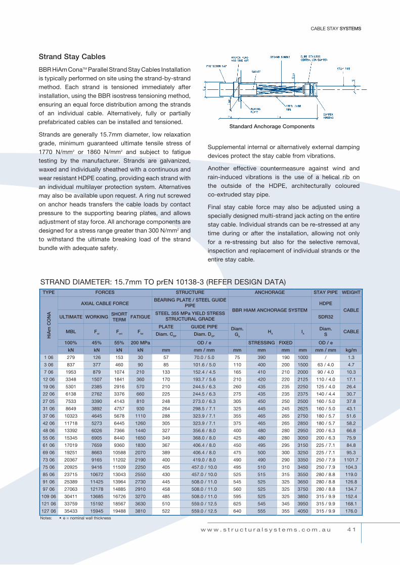
Strand Stay Cables
BBR HiAm ConaTM Parallel Strand Stay Cables Installation is typically performed on site using the strand-by-strand method. Each strand is tensioned immediately after installation, using the BBR isostress tensioning method, ensuring an equal force distribution among the strands of an individual cable. Alternatively, fully or partially prefabricated cables can be installed and tensioned.
Strandsaregenerally15.7mmdiameter, lowrelaxationgrade, minimum guaranteed ultimate tensile stress of 1770 N/mm2 or 1860 N/mm2 and subject to fatigue testing by the manufacturer. Strands are galvanized, waxed and individually sheathed with a continuous and wear resistant HDPE coating, providing each strand with an individual multilayer protection system. Alternatives may also be available upon request. A ring nut screwed on anchor heads transfers the cable loads by contact pressure to the supporting bearing plates, and allows adjustment of stay force. All anchorage components are designedforastressrangegreaterthan300N/mm2 and to withstand the ultimate breaking load of the strand bundle with adequate safety.
Supplemental internal or alternatively external damping devices protect the stay cable from vibrations.
Another effective countermeasure against wind and rain-induced vibrations is the use of a helical rib on the outside of the HDPE, architecturally coloured co-extruded stay pipe.
Final stay cable force may also be adjusted using a specially designed multi-strand jack acting on the entire stay cable. Individual strands can be re-stressed at any time during or after the installation, allowing not only for a re-stressing but also for the selective removal, inspection and replacement of individual strands or the entire stay cable.
Standard Anchorage Components
TYPE FORCES STRUCTURE ANCHORAGE STAY PIPE WEIGHT
HiA
m C
ON
A
AXIAL CABLE FORCEBEARING PLATE / STEEL GUIDE
PIPEBBR HIAM ANCHORAGE SYSTEM
HDPECABLE
ULTIMATE WORKINGSHORT TERM
FATIGUESTEEL 355 MPa YIELD STRESS
STRUCTURAL GRADE SDR32
MBL Fwl Fext Ffat
PLATE GUIDE PIPE Diam.GA
HA IA
Diam.S
CABLEDiam. CBP Diam. DGP
100% 45% 55% 200 MPa OD / e STRESSING FIXED OD / e
kN kN kN kN mm mm / mm mm mm mm mm mm / mm kg/m
1 06 279 126 153 30 57 70.0 / 5.0 75 390 190 1000 / 1.3
3 06 837 377 460 90 85 101.6 / 5.0 110 400 200 1500 63 / 4.0 4.7
7 06 1953 879 1074 210 133 152.4 / 4.5 165 410 210 2000 90 / 4.0 10.3
12 06 3348 1507 1841 360 170 193.7 / 5.6 210 420 220 2125 110 / 4.0 17.1
19 06 5301 2385 2916 570 210 244.5 / 6.3 260 435 235 2250 125 / 4.0 26.4
22 06 6138 2762 3376 660 225 244.5 / 6.3 275 435 235 2375 140 / 4.4 30.7
27 05 7533 3390 4143 810 248 273.0 / 6.3 305 450 250 2500 160 / 5.0 37.8
31 06 8649 3892 4757 930 264 298.5 / 7.1 325 445 245 2625 160 / 5.0 43.1
37 06 10323 4645 5678 1110 288 323.9 / 7.1 355 465 265 2750 180 / 5.7 51.6
42 06 11718 5273 6445 1260 305 323.9 / 7.1 375 465 265 2850 180 / 5.7 58.2
48 06 13392 6026 7366 1440 327 356.6 / 8.0 400 480 280 2950 200 / 6.3 66.8
55 06 15345 6905 8440 1650 349 368.0 / 8.0 425 480 280 3050 200 / 6.3 75.9
61 06 17019 7659 9360 1830 367 406.4 / 8.0 450 495 295 3150 225 / 7.1 84.8
69 06 19251 8663 10588 2070 389 406.4 / 8.0 475 500 300 3250 225 / 7.1 95.3
73 06 20367 9165 11202 2190 400 419.0 / 8.0 490 490 290 3350 250 / 7.9 1101.7
75 06 20925 9416 11509 2250 405 457.0 / 10.0 495 510 310 3450 250 / 7.9 104.3
85 06 23715 10672 13043 2550 430 457.0 / 10.0 525 515 315 3550 280 / 8.8 119.0
91 06 25389 11425 13964 2730 445 508.0 / 11.0 545 525 325 3650 280 / 8.8 126.8
97 06 27063 12178 14885 2910 458 508.0 / 11.0 560 525 325 3750 280 / 8.8 134.7
109 06 30411 13685 16726 3270 485 508.0 / 11.0 595 525 325 3850 315 / 9.9 152.4
121 06 33759 15192 18567 3630 510 559.0 / 12.5 625 545 345 3950 315 / 9.9 168.1
127 06 35433 15945 19488 3810 522 559.0 / 12.5 640 555 355 4050 315 / 9.9 176.0
StrAnd diAMEtEr: 15.7mm to prEn 10138-3 (rEFEr dESiGn dAtA)
Notes: • e = nominal wall thickness
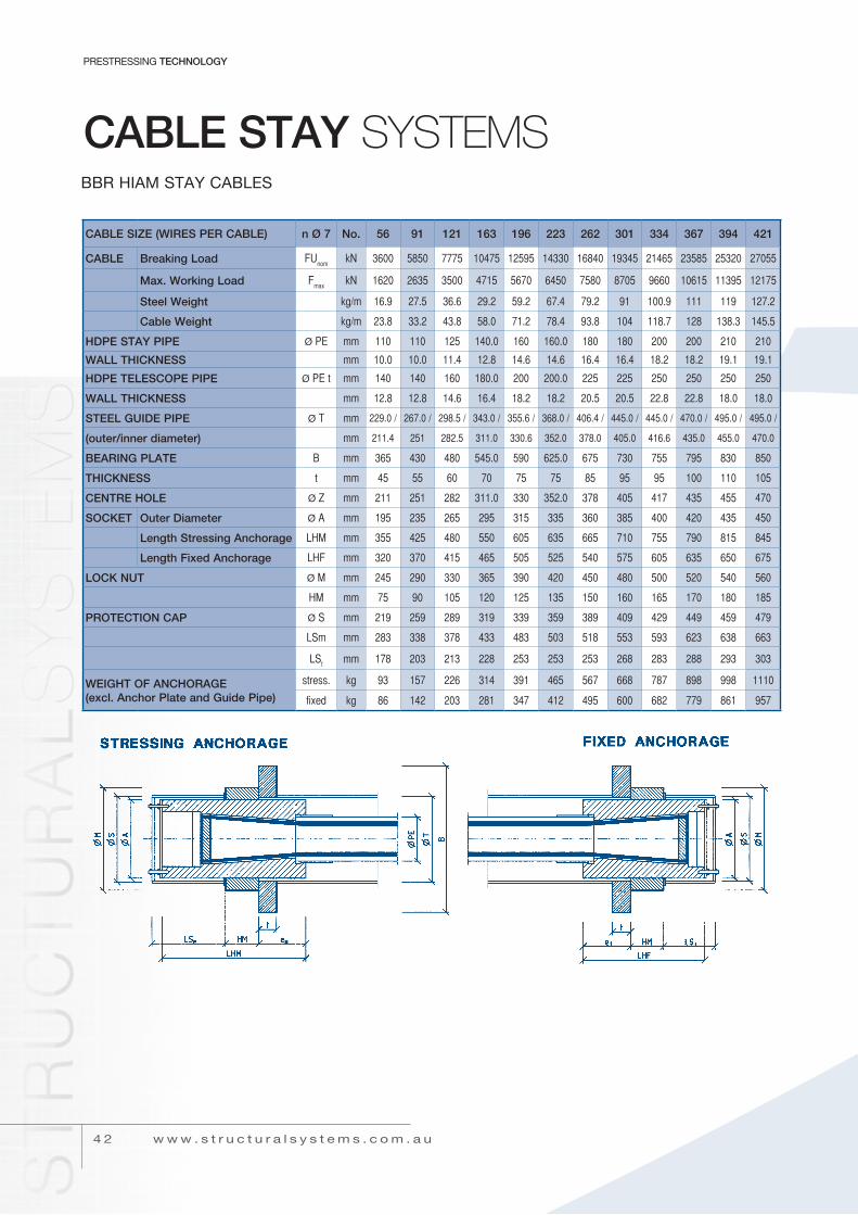
BBr HiAM StAY cABLES
4 2
PrEStrESSinG TECHNOLOGY
w w w . s t r u c t u r a l s y s t e m s . c o m . a u
CABLE STAY SySTEmS
CABLE SIzE (WIRES PER CABLE) n Ø 7 No. 56 91 121 163 196 223 262 301 334 367 394 421
CABLE Breaking Load Funom
kn 3600 5850 7775 10475 12595 14330 16840 19345 21465 23585 25320 27055
Max. Working Load Fmax
kn 1620 2635 3500 4715 5670 6450 7580 8705 9660 10615 11395 12175
Steel Weight kg/m 16.9 27.5 36.6 29.2 59.2 67.4 79.2 91 100.9 111 119 127.2
Cable Weight kg/m 23.8 33.2 43.8 58.0 71.2 78.4 93.8 104 118.7 128 138.3 145.5
HDPE STAY PIPE Ø pe mm 110 110 125 140.0 160 160.0 180 180 200 200 210 210
WALL THICKNESS mm 10.0 10.0 11.4 12.8 14.6 14.6 16.4 16.4 18.2 18.2 19.1 19.1
HDPE TELESCOPE PIPE Ø pe t mm 140 140 160 180.0 200 200.0 225 225 250 250 250 250
WALL THICKNESS mm 12.8 12.8 14.6 16.4 18.2 18.2 20.5 20.5 22.8 22.8 18.0 18.0
STEEL GUIDE PIPE Ø T mm 229.0 / 267.0 / 298.5 / 343.0 / 355.6 / 368.0 / 406.4 / 445.0 / 445.0 / 470.0 / 495.0 / 495.0 /
(outer/inner diameter) mm 211.4 251 282.5 311.0 330.6 352.0 378.0 405.0 416.6 435.0 455.0 470.0
BEARING PLATE B mm 365 430 480 545.0 590 625.0 675 730 755 795 830 850
THICKNESS t mm 45 55 60 70 75 75 85 95 95 100 110 105
CENTRE HOLE Ø Z mm 211 251 282 311.0 330 352.0 378 405 417 435 455 470
SOCKET Outer Diameter Ø a mm 195 235 265 295 315 335 360 385 400 420 435 450
Length Stressing Anchorage lhM mm 355 425 480 550 605 635 665 710 755 790 815 845
Length Fixed Anchorage lhF mm 320 370 415 465 505 525 540 575 605 635 650 675
LOCK NUT Ø M mm 245 290 330 365 390 420 450 480 500 520 540 560
hM mm 75 90 105 120 125 135 150 160 165 170 180 185
PROTECTION CAP Ø S mm 219 259 289 319 339 359 389 409 429 449 459 479
lSm mm 283 338 378 433 483 503 518 553 593 623 638 663
lSf
mm 178 203 213 228 253 253 253 268 283 288 293 303
WEIGHT OF ANCHORAGE (excl. Anchor Plate and Guide Pipe)
stress. kg 93 157 226 314 391 465 567 668 787 898 998 1110
fixed kg 86 142 203 281 347 412 495 600 682 779 861 957

4 3
cABLE StAY SYSTEMS
w w w . s t r u c t u r a l s y s t e m s . c o m . a u
BBr dinA StAY cABLES
CaBle Size (wireS per CaBle) n Ø 7 no. 13 22 31 37 55 70 91 103 121 145 157 181 199
CaBle Breaking load Funom
kn 835 1415 1990 2380 3535 4500 5850 6620 7775 9320 10090 11635 12790
Max. working load Fmax
kn 375 635 895 1070 1590 2025 2635 2980 3500 4195 4540 5235 5755
Steel weight kg/m 3.9 6.6 9.4 11.2 16.6 21.1 27.5 31.1 36.6 43.8 47.4 54.7 60.1
Cable weight kg/m 6.4 8.8 12.4 15.8 20.7 27.6 33.2 39.0 43.8 53.1 56.4 67.2 72.0
hdpe Stay pipe Ø pe mm 63 63 75 90 90 110 110 125 125 140 140 160 160
wall thiCKneSS mm 5.8 5.8 6.9 8.2 8.2 10.0 10.0 11.4 11.4 12.8 12.8 14.6 14.6
hdpe teleSCope pipe Ø pe mm 75 75 90 110 110 140 140 160 160 180 180 200 200
wall thiCKneSS mm 4.3 4.3 5.1 6.3 6.3 12.8 12.8 14.6 14.6 16.4 16.4 18.2 18.2
Steel guide pipe Stressing anchorage Ø Tm
mm 139.7 / 146.0 / 168.3 / 177.8 / 203.0 / 229.0 / 254.0 / 267.0 / 292.0 / 305.0 / 318.0 / 330.0 / 355.6 /
(inner / outer diameter) mm 125.5 136.0 155.7 165.2 190.4 211.4 238.0 245.0 267.0 285.0 298.0 310.0 327.2
Fixed anchorage Ø Tf
mm 139.7 / 146.0 / 168.3 / 177.8 / 203.0 / 229.0 / 254.0 / 267.0 / 292.0 / 305.0 / 318.0 / 330.0 / 355.6 /
(inner / outer diameter) mm 125.5 136.0 155.7 165.2 190.4 211.4 238.0 245.0 267.0 285.0 298.0 310.0 327.2
Bearing plate Stressing plate Bm
mm 230 260 285 305 350 380 420 435 470 510 525 560 590
thickness tm
mm 30 35 35 40 45 50 55 60 60 65 65 70 75
Centre hole Ø Zm
mm 125 136 155 165 190 211 238 245 267 285 298 310 327
Fixed plate Bf
mm 180 210 240 270 305 405 430 415 440 480 495 530 555
thickness tf
mm 25 35 35 45 45 70 80 60 65 75 75 80 90
Centre hole Ø Zf
mm 110 110 125 145 145 175 175 195 195 215 215 235 235
StreSSing SleeVe outer diameter Ø Zh mm 100 120 140 150 175 195 220 230 250 270 280 295 310
length lZh mm 90 105 115 130 160 190 205 225 245 255 270 290 305
length Fixed anchorage lhF mm 45 55 60 60 75 75 90 90 100 105 110 115 125
loCK nut Stressing anchorage Ø Mfmm 140 160 180 195 225 250 280 290 315 340 355 370 390
hMf
mm 30 35 40 45 55 60 70 70 75 80 85 90 95
Fixed anchorage Ø Mrmm 130 135 155 175 185 220 230 250 255 280 285 310 315
hMr
mm 30 40 45 50 55 65 70 75 80 85 90 95 100
proteCtion Cap Stressing anchorage Ø Smmm 129 149 169 179 199 219 249 259 279 299 309 319 339
lSm
mm 98 108 113 128 153 178 188 203 218 223 238 253 265
Fixed anchorage Ø Sfmm 125 130 150 170 180 215 225 245 250 275 280 305 310
lSf
mm 34 34 34 34 34 34 34 34 34 34 34 34 34
weight oF anChorage (excl. anchor plate and guide pipe)
stress. kg 15 19 26 34 48 69 86 102 125 150 169 199 230
fixed kg 11 12 16 22 24 35 40 49 52 65 69 85 90
4 4
PrEStrESSinG TECHNOLOGY
w w w . s t r u c t u r a l s y s t e m s . c o m . a u
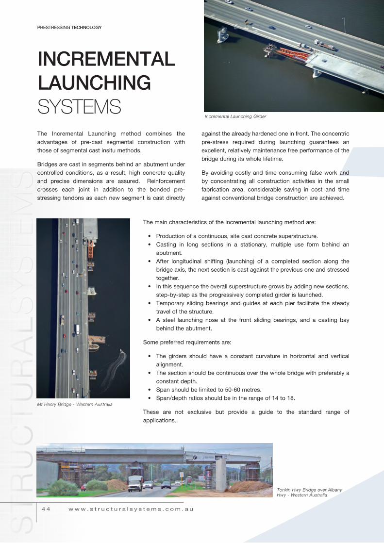
INCREMENTAL LAUNCHING SySTEmSthe incremental Launching method combines the advantages of pre-cast segmental construction with those of segmental cast insitu methods.
Bridges are cast in segments behind an abutment under controlled conditions, as a result, high concrete quality and precise dimensions are assured. reinforcement crosses each joint in addition to the bonded pre-stressing tendons as each new segment is cast directly
against the already hardened one in front. the concentric pre-stress required during launching guarantees an excellent, relatively maintenance free performance of the bridge during its whole lifetime.
By avoiding costly and time-consuming false work and by concentrating all construction activities in the small fabrication area, considerable saving in cost and time against conventional bridge construction are achieved.
the main characteristics of the incremental launching method are:
• Production of a continuous, site cast concrete superstructure.• casting in long sections in a stationary, multiple use form behind an
abutment.• After longitudinal shifting (launching) of a completed section along the
bridge axis, the next section is cast against the previous one and stressed together.
• in this sequence the overall superstructure grows by adding new sections, step-by-step as the progressively completed girder is launched.
• temporary sliding bearings and guides at each pier facilitate the steady travel of the structure.
• A steel launching nose at the front sliding bearings, and a casting bay behind the abutment.
Some preferred requirements are:
• the girders should have a constant curvature in horizontal and vertical alignment.
• the section should be continuous over the whole bridge with preferably a constant depth.
• Span should be limited to 50-60 metres.• Span/depth ratios should be in the range of 14 to 18.
these are not exclusive but provide a guide to the standard range of applications.
Incremental Launching Girder
Mt Henry Bridge - Western Australia
Tonkin Hwy Bridge over Albany Hwy - Western Australia

4 5
HEAVY LiFtinG SYSTEMS
in many instances, it is advantageous for extremely large and heavy components to be prefabricated away from their final location. in most cases they must be lowered, jacked horizontally or lifted into their final position. When their weight or size exceeds the capacity of available cranage other heavy lifting facilities must be considered.
Structural Systems has developed specialised lifting equipment for this application. the combination of the proven BBr Buttonhead Prestress cable together with electrically operated hydraulic jacking units allows virtually unlimited loads to be moved quickly and safely over any distance. the lifting or lowering operation can be accurately controlled through the hydraulic system which allows simultaneous or individual operation of each lifting unit.
HEAVY LIFTING SySTEmS
Perth Convention Exhibition Centre - Before Roof Lift
12 outlet isoflow pump and control panel
Perth Convention Exhibition Centre - After Roof Lift
4 3w w w . s t r u c t u r a l s y s t e m s . c o m . a u
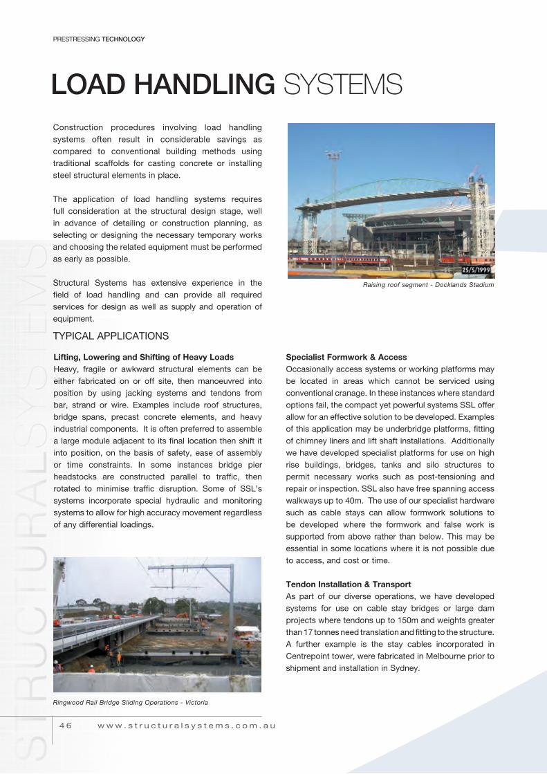
4 6
PrEStrESSinG TECHNOLOGY
w w w . s t r u c t u r a l s y s t e m s . c o m . a u
LOAD HANDLING SySTEmSConstruction procedures involving load handling systems often result in considerable savings as compared to conventional building methods using traditional scaffolds for casting concrete or installing steel structural elements in place.
The application of load handling systems requires full consideration at the structural design stage, well in advance of detailing or construction planning, as selecting or designing the necessary temporary works and choosing the related equipment must be performed as early as possible.
Structural Systems has extensive experience in the field of load handling and can provide all required services for design as well as supply and operation of equipment.
Raising roof segment - Docklands Stadium
lifting, lowering and shifting of Heavy loadsHeavy, fragile or awkward structural elements can be either fabricated on or off site, then manoeuvred into position by using jacking systems and tendons from bar, strand or wire. Examples include roof structures, bridge spans, precast concrete elements, and heavy industrial components. it is often preferred to assemble a large module adjacent to its final location then shift it into position, on the basis of safety, ease of assembly or time constraints. in some instances bridge pier headstocks are constructed parallel to traffic, then rotated to minimise traffic disruption. Some of SSL’s systems incorporate special hydraulic and monitoring systems to allow for high accuracy movement regardless of any differential loadings.
specialist Formwork & accessoccasionally access systems or working platforms may be located in areas which cannot be serviced using conventional cranage. in these instances where standard options fail, the compact yet powerful systems SSL offer allow for an effective solution to be developed. Examples of this application may be underbridge platforms, fitting of chimney liners and lift shaft installations. Additionally we have developed specialist platforms for use on high rise buildings, bridges, tanks and silo structures to permit necessary works such as post-tensioning and repair or inspection. SSL also have free spanning access walkways up to 40m. the use of our specialist hardware such as cable stays can allow formwork solutions to be developed where the formwork and false work is supported from above rather than below. this may be essential in some locations where it is not possible due to access, and cost or time.
Tendon Installation & TransportAs part of our diverse operations, we have developed systems for use on cable stay bridges or large dam projects where tendons up to 150m and weights greater than 17 tonnes need translation and fitting to the structure. A further example is the stay cables incorporated in centrepoint tower, were fabricated in Melbourne prior to shipment and installation in Sydney.
tYPicAL APPLicAtionS
Ringwood Rail Bridge Sliding Operations - Victoria

w w w . s t r u c t u r a l s y s t e m s . c o m . a u
load handling systems
Flat JacksFlat jacks are used for a variety of applications where structures are required to be lifted or preloaded and installation heights are to be kept to a minimum.
Structural Systems can provide 2 types of flat jacks:
• Pan Type Contstructed of two moulded steel sections welded together
used with a top and bottom plate. These can be inflated with oil or grout and are generally used only once (see Table a).
• Safety lock nut Type Solid ram, low height hydraulic jacks with safety lock nut for
mechanical load handling, used mainly for bearing replacement work (see Table B). For heavy loads multiples of the jacks are used linked through a manifold system.
Pan Type
Safety Lock Nut Type
notes: [1] flat jack thickness may vary slightly
taBlE a - PaN tYPE
tYPE OUtsIDE DIaMEtER
mm
MaXIMUM FORcE at 10,000 PsI
kN
tHIckNEss
mm
MaXIMUM tRaVEl
mm
INstallatION GaP
mm
60T100T150T200T250T300T
138188205240300305
60010001500200030003000
110162192155150170
285050505050
125180210170165185
taBlE B - saFEtY lOck NUt tYPE
Notes: • Jacks come complete with spherical testing
tYPE D OUtsIDE DIaMEtER
mm
MaXIMUM FORcE at 13.5 MPa
kN
EFFEctIVE aREa at ZERO EXtENsION
103mm2
t tHIckNEss1
mm
E MaXIMUM tRaVEl
mm
INstallatION GaPmm
9T16T39T52T60T78T108T160T217T347T540T738T898T1364T
1201502202502703003504204806007508709201150
85155390525605780108016052170347054007385897513635
6.411.529394558801191612574005476651010
2525252525252525252525252525
2525252525252525252525252525
3838383838383838383845454550
4 7

Structural Systems operate throughout Australia, South East Asia, the Middle East and the United Kingdom.For more information on Structural Systems and the many services we provide, visit: www.structuralsystems.com.au
STRUCTURAL SYSTEMS 112 Munro Street, South Melbourne VIC 3205 Australia T. +61 3 9296 8100 F. +61 3 9646 7133
STRUCTURAL SYSTEMS 20 Hilly Street, Mortlake NSW 2137 Australia T. +61 2 8767 6200 F. +61 2 8767 6299
STRUCTURAL SYSTEMS Unit 2, 16 Maiella Street, Stapylton QLD 4207 Australia T. +61 7 3442 3500 F. +61 7 3442 3555
STRUCTURAL SYSTEMS 24 Hines Road, O’Connor WA 6163 Australia T. +61 8 9267 5400 F. +61 8 9331 4511
NASA STRUCTURAL SYSTEMS LLC Head Office Suite 302 Sara Building, Garhoud PO Box 28987 DUBAI United Arab Emirates T. +97 14 2828 595 F. +97 14 2828 386 www.bbrstructuralsystems.com
STRUCTURAL SYSTEMS 12 Collett Way Great Western Industrial Park Southall, Middlesex UB2 4SE T. +44 208 843 6500 F. +44 208 843 6509
STRUCTURAL SYSTEMS Unit 13, Block G Maynooth Business Campus, Maynooth Co. Kildare, Ireland T. +353 1628 9124 F. +353 1628 9124
STRUCTURAL DESIGN SERVICES sp.z o.o. Twarda 30 00-831 Warszawa Poland T. +48 226 979 246 +48 226 979 247 F. +48 226 979 248
VICTORIA
NEW SOUTH WALES
QUEENSLAND
WESTERN AUSTRALIA
MIDDLE EAST REGION Bahrain, Oman, Qatar,
U.A.E.
UNITED KINGDOM
IRELAND
POLAND