Embed Size (px)
Citation preview

Post-Tensioning SystemsEuropean Technical Assessment
DSI monostrand prestressing system L1–L7 with cast iron anchors
Unbonded post-tensioning kits for prestressing of structures with 1 to 7 monostrands
09. April 2019
ETA-19/0077
European Organisation for Technical ApprovalsEuropäische Organisation für Technische ZulassungenOrganisation Européenne pour l‘Agrément Technique

Designated according to Article 29 of
Regulation (EU) No 305/2011INSTITUT FÜR BAUTEC
ÖS
www.eota.eu
Member of
Schenkenstrasse 4 1010 Vienna ι Austria
T +43 1 533 65 50 F +43 1 533 64 23
www.oib.or.at ι [email protected]
European Technical Assessment
ETA-19/0077 of 09.04.2019
General part
Technical Assessment Body issuing the European Technical Assessment
Trade name of the construction product
Product family to which the construction product belongs
Manufacturer
Manufacturing plant
This European Technical Assessment contains
This European Technical Assessment is issued in accordance with Regulation (EU) № 305/2011, on the basis of
Österreichisches Institut für Bautechnik (OIB) Austrian Institute of Construction Engineering
DSI monostrand prestressing system L1–L7 with cast iron anchors
Unbonded post-tensioning kits for prestressing of structures with 1 to 7 monostrands
DYWIDAG-Systems International GmbH Neuhofweg 5 85716 Unterschleissheim Germany
DYWIDAG-Systems International GmbH Max-Planck-Ring 1 40764 Langenfeld Germany
39 pages including Annexes 1 to 16, which form an integral part of this assessment.
EAD 160004-00-0301, European Assessment Document for Post-Tensioning Kits for Prestressing of Structures.

Page 2 of European Technical Assessment ETA-19/0077 of 09.04.2019
OIB-205-045/13-030
Table of contents EUROPEAN TECHNICAL ASSESSMENT ETA-19/0077 OF 09.04.2019 .......................................................... 1
GENERAL PART .......................................................................................................................................... 1
TABLE OF CONTENTS .................................................................................................................................. 2
REMARKS .................................................................................................................................................. 5
SPECIFIC PARTS ......................................................................................................................................... 5
1 TECHNICAL DESCRIPTION OF THE PRODUCT ........................................................................................ 5
1.1 GENERAL.......................................................................................................................................... 5
PT SYSTEM ................................................................................................................................................ 6
1.2 DESIGNATION AND RANGE OF ANCHORAGES AND COUPLINGS ............................................................... 6
1.2.1 Designation ..................................................................................................................................... 6
1.2.2 Anchorage and coupling .................................................................................................................. 6 1.2.2.1 General ......................................................................................................................................... 6 1.2.2.2 Stressing and fixed anchor ............................................................................................................ 6 1.2.2.3 Centre and edge distances of anchorages, concrete cover ........................................................... 7 1.2.2.4 Strength of concrete ...................................................................................................................... 7 1.2.2.5 Reinforcement in the anchorage zone ........................................................................................... 7 1.2.2.6 Fixed coupling ............................................................................................................................... 8 1.2.2.7 Movable coupling .......................................................................................................................... 8
1.3 DESIGNATION AND RANGE OF TENDONS .............................................................................................. 8
1.3.1 Designation ..................................................................................................................................... 8
1.3.2 Range of tendons ............................................................................................................................ 8
1.3.3 Maximum stressing forces ............................................................................................................... 8
1.4 SLIP AT ANCHORAGES AND COUPLINGS ............................................................................................... 8
1.5 FRICTION LOSSES ............................................................................................................................. 9
1.6 SUPPORT OF MONOSTRANDS ........................................................................................................... 10
1.7 RADII OF CURVATURE OF INTERNAL TENDONS ................................................................................... 10
COMPONENTS .......................................................................................................................................... 10
1.8 MONOSTRAND ................................................................................................................................ 10
1.8.1 Specification of prestressing steel strand ...................................................................................... 10
1.8.2 Specification of monostrand .......................................................................................................... 10
1.9 ANCHORAGE AND COUPLING COMPONENTS....................................................................................... 11
1.9.1 General ......................................................................................................................................... 11
1.9.2 Anchor body .................................................................................................................................. 11
1.9.3 Wedge ........................................................................................................................................... 11
1.9.4 PE-sleeve and transition tube ........................................................................................................ 11
1.9.5 Coupling head ............................................................................................................................... 11
1.9.6 Coupling sleeve ............................................................................................................................. 12
1.9.7 Protective cap, PE-cap .................................................................................................................. 12
1.9.8 Ancillary components for anchorage and coupling ......................................................................... 12
1.10 PERMANENT CORROSION PROTECTION ............................................................................................. 12

Page 3 of European Technical Assessment ETA-19/0077 of 09.04.2019
OIB-205-045/13-030
1.11 MATERIAL SPECIFICATIONS OF THE COMPONENTS ............................................................................. 12
2 SPECIFICATION OF THE INTENDED USE IN ACCORDANCE WITH THE APPLICABLE EUROPEAN ASSESSMENT DOCUMENT (HEREINAFTER EAD) ................................................................................ 12
2.1 INTENDED USE ................................................................................................................................ 12
2.2 ASSUMPTIONS ................................................................................................................................ 13
2.2.1 General ......................................................................................................................................... 13
2.2.2 Packaging, transport and storage .................................................................................................. 13
2.2.3 Design ........................................................................................................................................... 13
2.2.4 Installation ..................................................................................................................................... 13 2.2.4.1 General ....................................................................................................................................... 13 2.2.4.2 De-sheathing of monostrands ..................................................................................................... 14 2.2.4.3 Examination of tendons and possible repairs of the corrosion protection system ........................ 14 2.2.4.4 Fixed anchor ............................................................................................................................... 14 2.2.4.5 Stressing anchor ......................................................................................................................... 15 2.2.4.6 Fixed coupling FKM .................................................................................................................... 15 2.2.4.7 Movable coupling BK .................................................................................................................. 15 2.2.4.8 Welding at the anchorage ........................................................................................................... 16 2.2.4.9 Checking of tendons ................................................................................................................... 16 2.2.4.10 Stressing and stressing records ........................................................................................... 17 2.2.4.10.1 General .............................................................................................................................. 17 2.2.4.10.2 Stressing ............................................................................................................................ 17 2.2.4.10.3 Restressing ........................................................................................................................ 17 2.2.4.10.4 Stressing records ............................................................................................................... 17 2.2.4.10.5 Stressing equipment, clearance requirements and safety-at-work ..................................... 17
2.3 ASSUMED WORKING LIFE ................................................................................................................. 17
3 PERFORMANCES OF THE PRODUCT AND REFERENCES TO THE METHODS USED FOR ITS ASSESSMENT .................................................................................................................................. 18
3.1 ESSENTIAL CHARACTERISTICS ......................................................................................................... 18
3.2 PRODUCT PERFORMANCE ................................................................................................................ 19
3.2.1 Mechanical resistance and stability ............................................................................................... 19 3.2.1.1 Resistance to static load ............................................................................................................. 19 3.2.1.2 Resistance to fatigue ................................................................................................................... 19 3.2.1.3 Load transfer to the structure ...................................................................................................... 19 3.2.1.4 Friction coefficient ....................................................................................................................... 19 3.2.1.5 Deviation, deflection (limits) for internal and unbonded tendon ................................................... 19 3.2.1.6 Assessment of assembly............................................................................................................. 19 3.2.1.7 Corrosion protection .................................................................................................................... 19
3.2.2 Safety in case of fire ...................................................................................................................... 20 3.2.2.1 Reaction to fire ............................................................................................................................ 20
3.2.3 Hygiene, health, and the environment ........................................................................................... 20 3.2.3.1 Content, emission, and/or release of dangerous substances ...................................................... 20
3.3 ASSESSMENT METHODS .................................................................................................................. 20
3.4 IDENTIFICATION ............................................................................................................................... 20
4 ASSESSMENT AND VERIFICATION OF CONSTANCY OF PERFORMANCE (HEREINAFTER AVCP) SYSTEM APPLIED, WITH REFERENCE TO ITS LEGAL BASE..................................................................... 20
4.1 SYSTEM OF ASSESSMENT AND VERIFICATION OF CONSTANCY OF PERFORMANCE................................. 20
4.2 AVCP FOR CONSTRUCTION PRODUCTS FOR WHICH A EUROPEAN TECHNICAL ASSESSMENT HAS BEEN ISSUED .................................................................................................................................. 21

Page 4 of European Technical Assessment ETA-19/0077 of 09.04.2019
OIB-205-045/13-030
5 TECHNICAL DETAILS NECESSARY FOR THE IMPLEMENTATION OF THE AVCP SYSTEM, AS PROVIDED FOR IN THE APPLICABLE EAD ........................................................................................................... 21
5.1 TASKS FOR THE MANUFACTURER ..................................................................................................... 21
5.1.1 Factory production control ............................................................................................................. 21
5.1.2 Declaration of performance ........................................................................................................... 22
5.2 TASKS FOR THE NOTIFIED PRODUCT CERTIFICATION BODY ................................................................. 22
5.2.1 Initial inspection of the manufacturing plant and of factory production control ................................ 22
5.2.2 Continuing surveillance, assessment, and evaluation of factory production control ....................... 22
5.2.3 Audit-testing of samples taken by the notified product certification body at the manufacturing plant or at the manufacturer's storage facilities .............................................................................. 23
ANNEXES ................................................................................................................................................. 24
ANNEX 1 ANCHORAGE AND COUPLING – OVERVIEW – MAXIMUM PRESTRESSING FORCE ......................... 24
ANNEX 2 ANCHOR BODIES .................................................................................................................. 25
ANNEX 3 STRESSING ANCHOR SKM AND FIXED ANCHOR SFM ............................................................. 26
ANNEX 4 STRESSING ANCHOR MGS AND FIXED ANCHOR MGF ............................................................. 27
ANNEX 5 FIXED COUPLING FKM ......................................................................................................... 28
ANNEX 6 MOVABLE COUPLING BK ....................................................................................................... 29
ANNEX 7 ADDITIONAL REINFORCEMENT – CENTRE AND EDGE DISTANCES .............................................. 30
ANNEX 8 ADDITIONAL REINFORCEMENT – CENTRE AND EDGE DISTANCES .............................................. 31
ANNEX 9 MAXIMUM PRESTRESSING AND OVERSTRESSING FORCES ....................................................... 32
ANNEX 10 BASIC COMPONENTS OF ANCHORAGES .................................................................................. 33
ANNEX 11 PRESTRESSING STEEL STRANDS – CHARACTERISTIC MAXIMUM FORCE OF TENDON .................. 34
ANNEX 12 MATERIAL SPECIFICATIONS ................................................................................................... 35
ANNEX 13 TENDON INSTALLATION INSTRUCTIONS – FREE TENDON LAYOUT ............................................. 36
ANNEX 14 CONTENTS OF THE PRESCRIBED TEST PLAN ........................................................................... 37
ANNEX 15 AUDIT TESTING .................................................................................................................... 38
ANNEX 16 REFERENCE DOCUMENTS ..................................................................................................... 39

Page 5 of European Technical Assessment ETA-19/0077 of 09.04.2019
OIB-205-045/13-030
Remarks Translations of the European Technical Assessment in other languages shall fully correspond to the original issued document and should be identified as such. Communication of the European Technical Assessment, including transmission by electronic means, shall be in full. However, partial reproduction may be made with the written consent of Österreichisches Institut für Bautechnik. Any partial reproduction has to be identified as such.
Specific parts
1 Technical description of the product
1.1 General The European Technical Assessment – ETA – applies to a kit, the unbonded PT system
DSI monostrand prestressing system L1–L7 with cast iron anchors, comprising the following components.
− Tendon Unbonded tendon with 1 to 7 monostrands as tensile elements
− Tensile element 7-wire prestressing steel strand with nominal diameter and nominal tensile strengths as given in Table 1, factory provided with a corrosion protection system comprising a corrosion protection filling material and a PE-sheathing – Monostrand
Table 1 Tensile elements
Nominal diameter of prestressing steel strand
Designation according to
prEN 10138-3 1 Nominal tensile
strength
mm inch ⎯ N/mm2
15.7 0.62 Y1770S7 1 770
15.7 0.62 Y1860S7 1 860
NOTE 1 N/mm2 = 1 MPa
− Anchorage and coupling
The Monostrands are anchored by 3-piece wedges. Stressing (active) and fixed (passive) anchor with wedges and anchor body SKM, SFM, or MGS for a tendon with n = 1 to 7 monostrands Fixed coupling FKM with wedges, anchor body SKM, coupling head FKM, coupling sleeve FKM, and ancillary components for one single monostrand Movable coupling BK with wedges, coupling heads BK, coupling sleeve BK, and ancillary components for one single monostrand
1 Standards and other documents referred to in the European Technical Assessment are listed in Annex 16.
Page 6 of European Technical Assessment ETA-19/0077 of 09.04.2019
OIB-205-045/13-030
− Additional reinforcement in the anchorage zone for anchorage and fixed coupling
− Permanent corrosion protection system for tensile elements, anchorages, and couplings
PT system
1.2 Designation and range of anchorages and couplings
1.2.1 Designation The designation of anchorage or coupling is by its function in the structure and the number of monostrands. The first number indicates the nominal diameter of the prestressing steel strand, “68” = 15.7 mm (0.62 ''), followed by the maximum number of monostrands per unit “n”, 68 0n. E.g. 6807 as the designation for an anchorage with maximum 7 monostrands. Function within the structure is expressed as follows.
− SFM as fixed anchor for one single monostrand − SKM as stressing anchor for one single monostrand − MGF as fixed anchor for 2 to 7 monostrands − MGS as stressing anchor for 2 to 7 monostrands
− FKM as fixed coupling for one single monostrand − BK as movable coupling for one single monostrand The available anchorages and couplings are shown in Annex 1.
1.2.2 Anchorage and coupling
1.2.2.1 General The prestressing steel strands are anchored with ring wedges in conical holes of cast iron anchor bodies or steel coupling heads, see Annex 3, Annex 4, Annex 5, Annex 6, and Annex 10. The same principle of anchoring the prestressing steel strands applies to all sizes of anchorages and all couplings.
1.2.2.2 Stressing and fixed anchor Stressing and fixed anchor comprise 1-piece cast iron anchor body with 3-piece wedges and PE-sleeves or transition tubes, see Annex 3, Annex 4, and Annex 10. The cast iron anchor body serves for both, anchoring the prestressing steel strands and load transfer to the structural concrete via two load transfer planes. The PE-sleeve or transition tubes are attached to the anchor body and the prestressing steel strands are threaded into the anchor body through the PE-sleeve or transition tubes. An overlap between monostrand sheathing and PE-sleeve or transition tube is observed and the joint monostrand to PE-sleeve or transition tube is sealed with adhesive tape or sealing sleeve, see Annex 3 and Annex 4. After inserting the wedge, the anchor body is filled with corrosion protection filling material. The fixed anchor can be assembled either on the construction site same as the stressing anchor or preassembled with the monostrand in the factory. For fixed anchor
− SFM for one single monostrand, with washer, compression spring, and protective cap attached to secure the wedge seating, see Annex 3.
− MGF for 2 to 7 monostrands, with PE-caps placed over the ends of the prestressing steel strands and locking plate with gasket attached to secure the wedges, see Annex 4.
Fixed anchors do not require access during stressing and can be embedded in concrete, observing a cover of concrete on the caps of at least 20 mm.

Page 7 of European Technical Assessment ETA-19/0077 of 09.04.2019
OIB-205-045/13-030
For stressing anchors, once stressing is completed, the prestressing steel strands are cut, the anchor bodies filled with corrosion protection filling material and on anchor body
− SKM for one single monostrand a protective cap is screwed in, see Annex 3 and Annex 10. − MGS for 2 to 7 monostrands PE-caps are placed over the ends of the prestressing steel
strands and locking plate with gasket is attached, see Annex 4 and Annex 10. The additional reinforcement is placed and secured exactly centrically with regard to the anchor body, see Annex 7 and Annex 8.
1.2.2.3 Centre and edge distances of anchorages, concrete cover The minimum centre and edge distances of tendon anchorages and the actual mean compressive strength of concrete at time of stressing, f cm, 0, are given in Annex 7 and Annex 8. However, centre and edge distances of anchorages may be reduced in one direction by up to 15 %, but not smaller than the outer dimensions of the anchor body and placing of additional reinforcement remains still possible. In case of a reduction of the distances in one direction, the centre and edge distances in the perpendicular direction are increased by the same percentage in order to keep an equal concrete area in the anchorage zone. Under no circumstances concrete cover of the tendon falls below 20 mm nor below the concrete cover of the reinforcement installed in the same cross section. At the anchorage a concrete cover of at least 20 mm remains on the caps. Standards and regulations on concrete cover in force in the place of use are observed.
1.2.2.4 Strength of concrete Concrete according to EN 206 is used. At the time of transmission of the full prestressing force to the concrete structure the actual mean compressive strength of concrete, fcm, 0, cube or fcm, 0, cyl, is at least as given in Annex 7 and Annex 8, see Table 2. The actual mean compressive strength is verified by means of at least three specimens, cube of size 150 mm or cylinder with diameter of 150 mm and height of 300 mm, which are cured under the same conditions as the structure. For partial prestressing with 30 % of the full prestressing force, the actual mean value of the concrete compressive strength is at least 0.5 · fcm, 0, cube or 0.5 · fcm, 0, cyl. Intermediate values may be interpolated linearly according to Eurocode 2.
Table 2 Compressive strength of concrete
Concrete compressive strength Compressive strength in N/mm2
Cube, 150 mm fcm, 0, cube 23 27 30 35
Cylinder, 150 mm fcm, 0, cyl 19 22 25 28
1.2.2.5 Reinforcement in the anchorage zone Grade and dimensions of the additional reinforcement, are given in Annex 7, Annex 8, and Annex 12. Additional reinforcement is of closed stirrups or properly anchored orthogonal reinforcement. The reinforcement of the structure is not employed as additional reinforcement. Reinforcement exceeding the required reinforcement of the structure may be used as additional reinforcement if appropriate placing is possible. If required for a specific project design, the reinforcement given in Annex 7 and Annex 8 may be modified in accordance with the respective regulations in force at the place of use as well as with the relevant approval of the local authority and of the ETA holder to provide equivalent performance.

Page 8 of European Technical Assessment ETA-19/0077 of 09.04.2019
OIB-205-045/13-030
1.2.2.6 Fixed coupling The fixed coupling FKM is for one single monostrand only. It comprises stressing anchor SKM, coupling sleeve FKM, coupling head FKM, compression spring, washer, wedges, and PE sleeves. The fixed coupling FKM connects a second tendon, second construction stage, with a first tendon previously stressed on stressing anchor SKM, first construction stage. Coupling is achieved by the coupling sleeve FKM that is screwed into the anchor body SKM of the previously stressed tendon. The coupling head FKM of the second tendon is screwed onto the coupling sleeve FKM. For details regarding the fixed coupling FKM see Annex 5.
1.2.2.7 Movable coupling The movable coupling BK is for one single monostrand only. It comprises two coupling heads BK that are connected with a coupling sleeve BK, wedges, compression springs and washers. The movable coupling BK connects two tendons prior to stressing. Coupling is achieved by the coupling sleeve BK that is screwed into both coupling heads BK. For details regarding the movable coupling BK, see Annex 6.
1.3 Designation and range of tendons
1.3.1 Designation The tendon designation is by nominal diameter and number of the monostrands. The first number indicates the nominal diameter of the prestressing steel strand, “68” = 15.7 mm (0.62 ''), followed by the number of monostrands “n”, 68 0n, e.g. 6807 for a tendon with 7 monostrands.
1.3.2 Range of tendons The PT system includes tendons with 1, 2, 3, 4, 5, 6, and 7 monostrands according to Clause 1.1 and Annex 11. The monostrands of each tendon are anchored in stressing and fixed anchors according to Clause 1.1. Characteristic values of maximum force of the tendons are listed in Annex 11.
1.3.3 Maximum stressing forces Prestressing and overstressing forces are specified in the respective standards and regulations in force at the place of use. Annex 9 lists the maximum prestressing and overstressing forces of the tendons according to Eurocode 2. I.e. the maximum prestressing force applied to a tendon is not exceeding 0.90 Ap fp0.1. Overstressing with up to 0.95 Ap fp0.1 is only permitted if the force in the jack can be measured to an accuracy of 5 % of the final value of the prestressing force. Where
Ap ....... mm2 ........... Nominal cross-sectional area of prestressing steel, i.e. Ap = n S0
fp0.1 ..... N/mm2 .......... Characteristic 0.1 % proof stress of prestressing steel, i.e. Fp0.1 = fp0.1 S0
n ........... ⎯ ............. Number of prestressing steel strands, i.e. n = 1 to 7 S0 ....... mm2 ........... Nominal cross-sectional area of one single prestressing steel strand, see
Annex 11 Fp0.1 ...... kN ............. Characteristic value of 0.1 % proof force, see Annex 11
1.4 Slip at anchorages and couplings Slip at anchorages and couplings is taken into consideration in design and for determining tendon elongation. In Table 3 the slip, taken into account for determining elongation during stressing and of the prestressing force, and the required locking measures of wedges are specified. While the slip at the fixed anchor is considered for calculation of elongation only, the slip at the stressing end

Page 9 of European Technical Assessment ETA-19/0077 of 09.04.2019
OIB-205-045/13-030
occurs at force transfer from jack to anchorage and is considered for calculation of the prestressing force.
Table 3 Slip values and locking of wedges
Anchorage, coupling Slip Locking measures
⎯ mm ⎯
Stressing anchor 1), 2) SKM 6 ⎯
MGS 6 ⎯
Fixed anchor SFM 6 Protective cap, compression spring, and
washer
MGF 6 Gasket and locking plate
Fixed coupling SKM 1), 2) 6 ⎯
FKM 5 Washer and compression spring
Movable coupling BK 10 Washers and compression springs
NOTE 1) Slip at transfer of prestressing force from jack to anchorage. 2) Slip is 3 mm with power-seating of ~ 20 kN per strand
1.5 Friction losses The tendon layout should not feature abrupt changes of the tendon axis, since this may lead to significant additional friction losses. For calculation of losses of prestressing forces due to friction along a tendon Coulomb's friction law applies. Due to corrosion protection filling material and PE sheathing of the monostrand friction is very low. The calculation of friction losses is carried out by the equation
Px = P0 e − · ( + k · x) Where
Px .......... kN ............. Prestressing force at distance x along the tendon P0 .......... kN ............. Prestressing force at the distance x = 0 m ......... rad-1 ............ Friction coefficient, = 0.06 rad-1
.......... rad ............. Sum of the angular deviations over a distance x, irrespective of their direction or sign
k ........ rad/m ........... Wobble coefficient, k = 0.9 10-2 rad/m (= 0.5 °/m) x ........... m .............. Distance along the tendon from the point where the prestressing force is
equal to P0 NOTE 1 rad = 1 m/m = 1
Friction losses in the anchorages are low and do not have to be taken into consideration in design and execution.

Page 10 of European Technical Assessment ETA-19/0077 of 09.04.2019
OIB-205-045/13-030
1.6 Support of monostrands The monostrands are installed with high accuracy and are secured in their position. Spacing of tendon support is
1 Normally ....................................................................................................... 1.00 m For radius of curvature in normal cases see Clause 1.7.
2 Free tendon layout, see Annex 13, in maximum 450 mm thick slabs In the transition zone between a) high tendon position and anchorage (e.g. cantilever) ............................... 1.50 m
b) low and high tendon position or low tendon position and anchorage ........ 3.00 m At high and low tendon position, the tendons are connected in an appropriate way to the rebar mesh, at least at two points with spacing of 0.3 m to 1.0 m. The rebar mesh is fastened in its position. Special spacers for tendons are therefore not required. For details see Annex 13.
1.7 Radii of curvature of internal tendons The minimum allowable radius of curvature for internal tendons with prestressing steel strands of nominal diameter of 15.7 mm is 2.5 m. lf this radius is adhered to, verification of prestressing steel outer fibre stresses in curvatures is not required. The minimum allowable radius of curvature for deviation of a tendon with multistrand anchorages in the anchorage zone outside PE-sleeve or PE-transition tube is 3.5 m.
Components
1.8 Monostrand
1.8.1 Specification of prestressing steel strand 7-wire prestressing steel strands with plain surfaces of the individual wires, a nominal diameter of 15.7 mm, and tensile strengths of 1 770 N/mm2 or 1 860 N/mm2 are used. Dimensions and specifications of the prestressing steel strands are according to prEN 10138-3 and are given in Clause 1.1, Table 1, Table 4, and Annex 11.
1.8.2 Specification of monostrand The monostrands are 7-wire prestressing steel strands according to Clause 1.8.1, factory provided with a corrosion protection system comprising corrosion protection filling material and PE-sheathing, see Table 4.
Table 4 Monostrand
7-wire prestressing steel strand ⎯ Y1770S7 1) Y1860S7 1)
Nominal diameter of prestressing steel strand mm 15.7 2) 15.7 2)
Nominal cross-sectional area mm2 150 150
Characteristic tensile strength N/mm2 1 770 1 860
Mass of prestressing steel kg/m 1.17 1.17
Monostrand
External diameter of monostrand mm 20 20
Mass of monostrand kg/m 1.30 1.30 1) Designation according to prEN 10138-3 2) Corresponding to 0.62 inches

Page 11 of European Technical Assessment ETA-19/0077 of 09.04.2019
OIB-205-045/13-030
In the course of preparing the European Technical Assessment no characteristic has been assessed for the monostrand. In execution, a suitable monostrand that conforms to Annex 11 and is according to the standards and regulations in force at the place of use is taken.
1.9 Anchorage and coupling components
1.9.1 General Specifications of anchorage and coupling components are given in the Annexes and the technical file2 of the European Technical Assessment. Therein the components’ dimensions, materials, material identification data with tolerances and the materials used in corrosion protection are specified.
1.9.2 Anchor body The anchor body is made of cast iron and provides holes for anchoring the prestressing steel strands, see Annex 2 and Annex 10. At one end the holes are conical to accommodate prestressing steel strands and wedges. The anchor body is employed as stressing and fixed anchor. All conical holes are countersunk and deburred. See Annex 10 for details on the conical holes. For installation the holes and cones are clean and free of damage or rust and are provided with corrosion protection oil.
1.9.3 Wedge The PT-system includes two wedges that are in three pieces, 68 00 0037 and 68 00 0040, see Annex 10. − Wedge 68 00 0037 is for fixed coupling FKM, 2nd construction stage, and for movable
coupling BK. Coupling head FKM and coupling unit BK are delivered with preassembled wedges to the construction site.
− Wedge 68 00 0040 is for fixed and stressing anchors SFM, SKM, MGF, and MGS, and for the 1st construction stage of the fixed coupling FKM.
1.9.4 PE-sleeve and transition tube PE-sleeve and transition tube are of HD PE, see Annex 10. − The PE-sleeve is screwed on the anchor body SKM and the coupling head FKM. − The transition tube is inserted into the anchor body MGS. PE-sleeve and transition tube overlap the monostrand at anchorage and fixed coupling to facilitate the transition monostrand to anchorage.
1.9.5 Coupling head The coupling heads FKM and BK are in steel, see Annex 5 and Annex 6. Conical bores are provided to accommodate prestressing steel strand and wedge. At one end of the coupling head there is a cylindrical extension with an internal thread to screw onto the coupling sleeve. All conical and cylindrical bores are countersunk and deburred. See Annex 10 for details on the conical bores. For installation the bores and cones are clean and free of damage or rust and are provided with corrosion protection oil.
2 The technical file of the European Technical Assessment is deposited at Österreichisches Institut für Bautechnik.

Page 12 of European Technical Assessment ETA-19/0077 of 09.04.2019
OIB-205-045/13-030
1.9.6 Coupling sleeve The coupling sleeves FKM and BK are in steel, see Annex 5 and Annex 6. The coupling sleeves are cylindrical parts with a centre bore and an external thread. They are screwed into
− Stressing anchor SKM and coupling head FKM to establish the connection at the fixed coupling with coupling sleeve FKM.
− Both coupling heads BK to establish the connection at the movable coupling with coupling sleeve BK.
1.9.7 Protective cap, PE-cap The protective cap is made of plastic, see Annex 10, encases the corrosion protection filling material and seals the tendon end at the anchorages SKM and SFM. At the fixed anchor SFM, the protective cap together with a compression spring and a washer hold the wedge in place, see Annex 1, Annex 3, and Annex 10. The PE-cap is made of HD PE, see Annex 10, encases the corrosion protection filling material and seals the protruding end of the prestressing steel strand at the anchorages MGS and MGF.
1.9.8 Ancillary components for anchorage and coupling Compression spring and washer at the fixed anchor SFM, at the fixed coupling FKM, and at the movable coupling BK hold the wedge in place. Compression spring and washer are made of steel. PE-caps, gasket, and locking plate secure the wedges at the fixed anchor MGF and seal the anchorage at the fixed and stressing anchor MGF and MGS. The locking plate is made of steel.
1.10 Permanent corrosion protection In the course of preparing the European Technical Assessment no characteristic has been assessed for components and materials of the corrosion protection system. In execution, all components or materials are selected according to the standards and regulations in force at the place of use. The prestressing steel strand is provided in the factory with corrosion protection consisting of corrosion protective filling material and extruded PE-sheathing – Monostrand. Application of corrosion protection in the anchorage zone is described in the assembly instructions in Clause 2.2.4. The de-sheathed prestressing steel strand is completely covered by PE-sleeve or transition tube. In the final stage the PE-sleeve or transition tube overlaps the PE-sheathing of the monostrand by at least 80 mm. The transition joint monostrand to PE-sleeve or transition tube is sealed and the void in the anchorage zone is completely filled with a corrosion protection filling material.
1.11 Material specifications of the components Material specifications of the components are given in Annex 12.
2 Specification of the intended use in accordance with the applicable European Assessment Document (hereinafter EAD)
2.1 Intended use The PT system DSI monostrand prestressing system L1–L7 with cast iron anchors is intended to be used for the prestressing of structures. Use category according to tendon configuration and material of structure is − Internal unbonded tendon for concrete and composite structures

Page 13 of European Technical Assessment ETA-19/0077 of 09.04.2019
OIB-205-045/13-030
2.2 Assumptions
2.2.1 General Concerning product packaging, transport, storage, maintenance, replacement, and repair it is the responsibility of the manufacturer to undertake the appropriate measures and to advise his clients on transport, storage, maintenance, replacement, and repair of the product as he considers necessary.
2.2.2 Packaging, transport and storage Tendons and anchorages may be assembled on site or at the factory, i.e. pre-assembled tendons. During transport, the tendons may be wind to a coil with a minimum internal diameter of 1.5 m or as specified by the manufacturer of the monostrand. Advice on packaging, transport, and storage includes. − Temporary protection of prestressing steel and components in order to prevent corrosion
during transportation from production site to construction site
− Transportation, storage, and handling of prestressing steel and other components in a manner as to avoid damage by mechanical or chemical impact
− Protection of tensile elements and other components from moisture
− Keeping tensile elements away from zones where welding operations are performed
2.2.3 Design Advice on design includes.
− Design of the structure permits correct installation and stressing of tendons and design and reinforcement of the anchorage zone permits correct placing and compacting of concrete.
− Verification of transfer of stressing forces to the structural concrete is not required, if centre and edge distances of the tendons, strength of concrete, as well as grade and dimensions of additional reinforcement, see Clause 1.2.2.3, Clause 1.2.2.4, Clause 1.2.2.5, Annex 7, and Annex 8 are conformed to. The forces outside the area of additional reinforcement are verified and, if necessary, covered by appropriate, in general transverse reinforcement. The reinforcement of the structure is not employed as additional reinforcement. Reinforcement exceeding the required reinforcement of the structure may be used as additional reinforcement if appropriate placing is possible.
− The anchor recess is designed as to ensure a concrete cover of at least 20 mm at the caps in the final state.
− Bursting out of prestressing steels in case of failure is prevented. Sufficient protection is provided by e.g. a cover of reinforced concrete.
− The initial prestressing force applied to the stressing anchor will decrease especially as a result of slip, see Clause 1.4, friction along the tendon, see Clause 1.5, and of the elastic shortening of the structure, and in the course of time because of relaxation of the prestressing steel, and creep and shrinkage of concrete. The stressing instructions prepared by the ETA holder should be consulted.
− In the fixed coupling, the prestressing force at the 2nd construction stage is not greater than at the 1st construction stage, neither during construction, nor in the final state, nor due to any load combination.
2.2.4 Installation
2.2.4.1 General It is assumed that the product will be installed according to the manufacturer’s instructions or – in absence of such instructions – according to the usual practice of the building professionals.
Page 14 of European Technical Assessment ETA-19/0077 of 09.04.2019
OIB-205-045/13-030
Assembly and installation of tendons are only carried out by qualified PT specialist companies with the required resources and experience in the use of unbonded multi-strand post-tensioning systems, see CWA 14646. The company’s PT site manager has a certificate, stating that she or he has been trained by the ETA holder and that she or he possesses the necessary qualification and experience with the internal unbonded prestressing system DSI monostrand prestressing system L1–L7 with cast iron anchors. Anchor bodies are placed perpendicular to the tendon’s axis. At the anchorages the tendon layout continues with a straight length of at least 125 mm. Couplings are placed in straight tendon sections only. The centric position of the additional reinforcement is secured by tying or by means of spacers braced against the tendon. In the final stage the voids in anchorages, couplings, and PE-sleeves or transition tubes are completely filled with corrosion protection filling material. The PE-sleeve or transition tube overlaps the monostrand sheathing by at least 80 mm and the monostrand sheathing does not press against the anchorage. This is checked by applied markings before concreting.
2.2.4.2 De-sheathing of monostrands The length along which the monostrand sheathing is removed at the stressing anchor depends on the variations in temperature to be expected between installation and concreting. PE-sleeve or transition tube overlaps the monostrand sheathing, but the monostrand sheathing does not press against the anchorage. This is checked prior to concreting by applied markings.
2.2.4.3 Examination of tendons and possible repairs of the corrosion protection system During installation careful handling of tendons is ensured. Before concreting the PT site manager carries out a final examination of the installed tendons. Damages to PE sheathings, which cause or may cause leaking of corrosion protection filling material, are repaired. Repair is in accordance with the respective load requirements and suitable for operating temperatures up to 30 °C.
2.2.4.4 Fixed anchor The fixed anchor is either prefabricated or assembled at the construction site. In case of inaccessible fixed anchor SFM the protective cap together with compression spring and washer is screwed on before or at tendon installation to secure the wedge, see Annex 3. For fixed anchor MGF the wedges are secured with PE-caps, gasket, and locking plate, see Annex 4. In general, the fixed anchor is factory assembled. Factory assembly comprises the following steps.
− Screw PE-sleeve onto the anchor body or attach PE-transition tubes to the anchor body. − Place the wedges into the conical holes of the anchor body. − Fill in a measured quantity of corrosion protection filling material.
− For anchorage SFM screw on the protection cap filled with corrosion protection filling material together with compression spring and washer.
− Remove PE sheathing from the monostrand over a length of 50 to 60 mm. − Insert the de-sheathed monostrand through the PE-sleeve or transition tube, observing the
overlap length PE-sleeve or transition tube to monostrand. − Attach PE-caps with gasket and locking plate on anchorage MGF.
− Wipe off corrosion protection filling material that has leaked out and seal the joint monostrand to PE-sleeve or transition tube.
− Cut the monostrand from the coil, observing the required tendon length.

Page 15 of European Technical Assessment ETA-19/0077 of 09.04.2019
OIB-205-045/13-030
2.2.4.5 Stressing anchor The anchor body is fastened to the formwork on site and connected to the monostrand. It can also be used as an accessible fixed anchor. Site assembly comprises the following steps, see Annex 3 and Annex 4. − Fastening the anchor body with assembled PE-sleeve or transition tube and with recess
form onto the formwork. For stressing anchor SKM an installation spindle with sealing and nut is used. Stressing anchor MGS is installed with a sealing ring towards the formwork.
− Hold the monostrand towards the anchorage to mark cutting point and overlapping length on the PE sheathing.
− Cut and pull off the PE sheathing from the monostrand.
− Insert the monostrand through PE-sleeve or transition tube and anchor body. − Check overlapping length between monostrand and PE-sleeve or transition tube. − Fill PE-sleeves or transition tube with corrosion protection filling material and seal joint
monostrand to PE-sleeve or transition tube. − Place the previously removed PE sheathing onto the end of the prestressing steel strand in
order to protect the strand protrusion until stressing. For prefabricated tendons the first step is done later on site. The other steps are carried out in identical order and the prefabricated tendons are prepared, e.g. coiled, for transport.
2.2.4.6 Fixed coupling FKM The anchorage of the 1st construction stage is installed and stressed same as the stressing anchor SKM. Site assembly of the 2nd construction stage comprises the following steps, see Annex 5. − Screw the pre-assembled coupling head FKM and coupling sleeve FKM into the internal
thread of the stressing anchor SKM. − Fill a sufficient quantity of corrosion protection filling material into the expanded section of
the PE-sleeve and slip the PE-sleeve onto the monostrand.
− Remove approximately 120 mm of the monostrand PE-sheathing. − Apply a coloured marking on the monostrand. − Push the de-sheathed strand into the coupling head FKM. The wedge pushed forward by
the compression spring retains the prestressing steel strand.
− Check the insertion depth by means of the coloured marking. − Seal the joint monostrand to PE-sleeve with sealing sleeve or adhesive tape.
2.2.4.7 Movable coupling BK Site assembly comprises the following steps, see Annex 6. Tendon № 1 − Remove approximately 120 mm of the monostrand PE-sheathing.
− Apply a coloured marking on the monostrand. − Place the PE-protective tube section 1 onto the monostrand. − Fill a sufficient quantity of corrosion protection filling material into the expanded section of
the PE-protective tube section 1.

Page 16 of European Technical Assessment ETA-19/0077 of 09.04.2019
OIB-205-045/13-030
Tendon № 2 − Remove the PE-sheathing of the monostrand along a length equal to that of the protective
tube minus 100 mm. − Apply a coloured marking on the monostrand. − Place the PE-protective tube section 2 with the sealing sleeve onto the monostrand. Coupling
− Place the pre-assembled coupling unit with coupling heads BK, coupling sleeve BK, wedges, springs, washers, and filled with corrosion protection filling material onto the de-sheathed prestressing steel strand of tendon № 1 up to the locking steel pin.
− Insert the de-sheathed prestressing steel strand of tendon № 2 into the coupling up to the locking steel pin.
− The wedges pushed forwards by the compression springs retain both prestressing steel strands.
− Check insertion depths of the monostrands by means of the coloured markings on both sides of the coupling.
Corrosion protection − Push forward the PE-protective tube over the coupling and ensure corrosion protection
filling material leaks out between protective tube and PE-sheathing of the monostrand of tendon № 1.
− Press the securing pin into the PE-protective tube section 1 to secure the position of the coupling. Ensure sufficient clearance within PE-protective tube section 2 to allow for unimpeded displacement of the coupling during stressing.
− Push forward the PE-protective tube section 2 to approximately 20 mm before the end of the expanded section of the PE-protective tube 1.
− Seal the joint of monostrand № 2 to PE-protective tube section 2 with sealing sleeve or adhesive tape.
− Inject corrosion protection filling material through the injection nipple of the PE-protective tube section 2 until the corrosion protection filling material begins to spill out at the annular gap between PE-protective tube section 1 and PE-protective tube section 2.
− Clean the PE-components from the excess corrosion protection filling material and seal the joint PE-protective tube section 1 to PE-protective tube section 2 with adhesive tape.
− Seal the joint monostrand № 1 to PE-protective tube section 1 with sealing sleeve or adhesive tape.
2.2.4.8 Welding at the anchorage Welding operations are not intended to be performed on components of the DSI monostrand prestressing system L1–L7 with cast iron anchors. After the tendons have been prefabricated or installed, welding operations are not conducted any more. In case of welding operation close to tendons precautionary measures are required to avoid any damage.
2.2.4.9 Checking of tendons The tendons are carefully handled during installation. Prior to placing the concrete, the responsible person performs a final check on the installed tendons, see Clause 2.2.4.3.
Page 17 of European Technical Assessment ETA-19/0077 of 09.04.2019
OIB-205-045/13-030
2.2.4.10 Stressing and stressing records
2.2.4.10.1 General The geometrical properties of anchor bodies, centre and edge distances and additional reinforcement of tendon anchorages are specified in Annex 2, Annex 7, and Annex 8.
2.2.4.10.2 Stressing With a mean concrete compressive strength in the anchorage zone according to Annex 7 and Annex 8 full prestressing may be applied. The prestressing forces are applied in accordance with a prescribed stressing schedule. Said schedule includes time and sequence of the various prestressing levels and the elongations calculated for the tendons, the required mean cube compressive strength of the concrete as well as time and kind of formwork lowering and removal. Any possible spring back forces of the falsework are taken into account. Prestressing comprises the following steps − Remove the PE protective sheathing from the strand protrusion. − Fill the void in the anchorage with corrosion protection filling material using a thin injection
lance.
− Place the wedges into the conical holes of the stressing anchor. − Stress with prestressing jack. − Measure tendon elongation during stressing.
− Cut off the strand protrusion with a cutting disk or cutting tool.
− Screw on the protective cap on anchorage SKM or attach PE-caps, gasket, and locking plate on anchorage MGS. The caps are filled with corrosion protection filling material.
− Fill the anchor recess with concrete.
2.2.4.10.3 Restressing Restressing of tendons before final cutting of strand protrusions in combination with release and reuse of wedges is permitted. After restressing, the wedges bite into at least 15 mm of virgin strand surface and no wedge bite remains on the tendon between the anchorages.
2.2.4.10.4 Stressing records Any important observations made during the stressing operation, in particular prestressing forces applied and elongation measured, are recorded in a stressing record for each tendon.
2.2.4.10.5 Stressing equipment, clearance requirements and safety-at-work For stressing, hydraulic jacks are used. Information about the stressing equipment has been submitted to Österreichisches Institut für Bautechnik. To stress the tendons, clearance of approximately 1 m directly behind the anchorage is required. The ETA holder keeps available more detailed information on the jacks used and the required space for handling and stressing. The safety-at-work and health protection regulations are observed.
2.3 Assumed working life The European Technical Assessment is based on an assumed working life of the DSI monostrand prestressing system L1–L7 with cast iron anchors of 100 years, provided that the DSI monostrand prestressing system L1–L7 with cast iron anchors is subject to appropriate installation, use, and maintenance, see Clause 2.2. These provisions are based upon the current state of the art and the available knowledge and experience.

Page 18 of European Technical Assessment ETA-19/0077 of 09.04.2019
OIB-205-045/13-030
In normal use conditions the real working life may be considerably longer without major degradation affecting the basic requirements for works3. The indications given as to the working life of the construction product cannot be interpreted as a guarantee, neither given by the product manufacturer or his representative nor by EOTA nor by the Technical Assessment Body, but are regarded only as a means for expressing the expected economically reasonable working life of the product.
3 Performances of the product and references to the methods used for its assessment
3.1 Essential characteristics The performances of the DSI monostrand prestressing system L1–L7 with cast iron anchors for the essential characteristics are given in Table 5.
Table 5 Essential characteristics and performances of the product
№ Essential characteristic Product performance
Basic requirement for construction works 1: Mechanical resistance and stability
1 Resistance to static load See Clause 3.2.1.1
2 Resistance to fatigue See Clause 3.2.1.2.
3 Load transfer to the structure See Clause 3.2.1.3.
4 Friction coefficient See Clause 3.2.1.4.
5 Deviation, deflection (limits) for internal bonded and unbonded tendon See Clause 3.2.1.5.
6 Assessment of assembly See Clause 3.2.1.6.
7 Corrosion protection See Clause 3.2.1.7.
Basic requirement for construction works 2: Safety in case of fire
8 Reaction to fire See Clause 3.2.2.1.
Basic requirement for construction works 3: Hygiene, health, and the environment
9 Content, emission, and/or release of dangerous substances See Clause 3.2.3.1.
Basic requirement for construction works 4: Safety and accessibility in use
⎯ Not relevant. No characteristic assessed. ⎯
Basic requirement for construction works 5: Protection against noise
⎯ Not relevant. No characteristic assessed. ⎯
3 The real working life of a product incorporated in a specific works depends on the environmental conditions to which that
works are subject, as well as on the particular conditions of design, execution, use, and maintenance of that works. Therefore, it cannot be excluded that in certain cases the real working life of the product may also be shorter than the assumed working life.
Page 19 of European Technical Assessment ETA-19/0077 of 09.04.2019
OIB-205-045/13-030
№ Essential characteristic Product performance
Basic requirement for construction works 6: Energy economy and heat retention
⎯ Not relevant. No characteristic assessed. ⎯
Basic requirement for construction works 7: Sustainable use of natural resources
⎯ No characteristic assessed. ⎯
3.2 Product performance
3.2.1 Mechanical resistance and stability
3.2.1.1 Resistance to static load The PT system as described in the ETA meets the acceptance criteria of EAD 160004-00-0301, Clause 2.2.1. The characteristic value of maximum force, Fpk, of the tendon with prestressing steel strands according to Annex 11 is given in Annex 11.
3.2.1.2 Resistance to fatigue The PT system as described in the ETA meets the acceptance criteria of EAD 160004-00-0301, Clause 2.2.2. The characteristic value of maximum force, Fpk, of the tendon with prestressing steel strands according to Annex 11 is given in Annex 11. The fatigue resistance of anchorages and couplings was tested and verified with an upper force of 0.65 Fpk, a fatigue stress range of 80 N/mm2, and 2 106 load cycles.
3.2.1.3 Load transfer to the structure The PT system as described in the ETA meets the acceptance criteria of EAD 160004-00-0301, Clause 2.2.3. The characteristic values of maximum force, Fpk, of the tendon with prestressing steel strands according to Annex 11 is given in Annex 11. Conformity with the stabilisation and crack width criteria specified for the load transfer test was verified to a force level of 0.80 Fpk.
3.2.1.4 Friction coefficient For friction losses including friction coefficient see Clause 1.5.
3.2.1.5 Deviation, deflection (limits) for internal and unbonded tendon For minimum radius of curvature of internal tendons see Clause 1.7.
3.2.1.6 Assessment of assembly The PT system as described in the ETA meets the acceptance criteria of EAD 160004-00-0301, Clause 2.2.7
3.2.1.7 Corrosion protection The PT system as described in the ETA meets the acceptance criteria of EAD 160004-00-0301, Clause 2.2.13

Page 20 of European Technical Assessment ETA-19/0077 of 09.04.2019
OIB-205-045/13-030
3.2.2 Safety in case of fire
3.2.2.1 Reaction to fire The performance of components made of steel or cast iron is Class A1 without testing. The performance of components of other materials has not been assessed.
3.2.3 Hygiene, health, and the environment
3.2.3.1 Content, emission, and/or release of dangerous substances According to the manufacturer’s declaration, the PT system does not contain dangerous substances. − SVOC and VOC
The performance of components made of steel or cast iron that are free of coating with organic material is no emission of SVOC and VOC. The performance of components of other materials has not been assessed.
− Leachable substances The product is not intended to be in direct contact to soil, ground water, and surface water.
3.3 Assessment methods The assessment of the essential characteristics in Clause 3.1 of the DSI monostrand prestressing system L1–L7 with cast iron anchors, for the intended use, and in relation to the requirements for mechanical resistance and stability, safety in case of fire, and for hygiene, health, and the environment in the sense of the basic requirements for construction works № 1, 2, and 3 of Regulation (EU) № 305/2011, has been made in accordance with Annex A of EAD 160004-00-0301, Post-Tensioning kits for prestressing of structures, for item 2, Internal unbonded PT systems.
3.4 Identification The European Technical Assessment for the DSI monostrand prestressing system L1–L7 with cast iron anchors is issued on the basis of agreed data that identify the assessed product4. Changes to materials, to composition, or to characteristics of the product, or to the production process could result in these deposited data being incorrect. Österreichisches Institut für Bautechnik should be notified before the changes are introduced, as an amendment of the European Technical Assessment is possibly necessary.
4 Assessment and verification of constancy of performance (hereinafter AVCP) system applied, with reference to its legal base
4.1 System of assessment and verification of constancy of performance According to Commission Decision 98/456/EC the system of assessment and verification of constancy of performance to be applied to the DSI monostrand prestressing system L1–L7 with cast iron anchors is System 1+. System 1+ is detailed in Commission Delegated Regulation (EU) № 568/2014 of 18 February 2014, Annex, point 1.1, and provides for the following items. (a) The manufacturer shall carry out
(i) factory production control;
4 The technical file of the European Technical Assessment is deposited at Österreichisches Institut für Bautechnik.

Page 21 of European Technical Assessment ETA-19/0077 of 09.04.2019
OIB-205-045/13-030
(ii) further testing of samples taken at the manufacturing plant by the manufacturer in accordance with the prescribed test plan5.
(b) The notified product certification body shall decide on the issuing, restriction, suspension, or withdrawal of the certificate of constancy of performance of the construction product on the basis of the outcome of the following assessments and verifications carried out by that body (i) an assessment of the performance of the construction product carried out on the basis of
testing (including sampling), calculation, tabulated values, or descriptive documentation of the product;
(ii) initial inspection of the manufacturing plant and of factory production control; (iii) continuing surveillance, assessment, and evaluation of factory production control; (iv) audit-testing of samples taken by the notified product certification body at the
manufacturing plant or at the manufacturer's storage facilities.
4.2 AVCP for construction products for which a European Technical Assessment has been issued Notified bodies undertaking tasks under System 1+ shall consider the European Technical Assessment issued for the construction product in question as the assessment of the performance of that product. Notified bodies shall therefore not undertake the tasks referred to in Clause 4.1, point (b) (i).
5 Technical details necessary for the implementation of the AVCP system, as provided for in the applicable EAD
5.1 Tasks for the manufacturer
5.1.1 Factory production control The kit manufacturer exercises permanent internal control of the production. All the elements, procedures, and specifications adopted by the kit manufacturer are documented in a systematic manner in the form of written policies and procedures. − Control of the incoming materials
The manufacturer checks the incoming materials to establish conformity with their specifications.
− Inspection and testing Kind and frequency of inspections, tests, and checks, conducted during production and on the final product normally include. − Definition of the number of samples taken by the kit manufacturer − Material properties e.g. tensile strength, hardness, surface finish, chemical composition,
etc.
− Determination of the dimensions of components − Check correct assembly − Documentation of tests and test results
All tests are performed according to written procedures with suitable calibrated measuring devices. All results of inspections, tests, and checks are recorded in a consistent and systematic way. The basic elements of the prescribed test plan are given in Annex 14, conform to
5 The prescribed test plan has been deposited with Österreichisches Institut für Bautechnik and is handed over only to the
notified product certification body involved in the procedure for the assessment and verification of constancy of performance. The prescribed test plan is also referred to as control plan.

Page 22 of European Technical Assessment ETA-19/0077 of 09.04.2019
OIB-205-045/13-030
EAD 160004-00-0301, Table 3, and are specified in the quality management plan of the DSI monostrand prestressing system L1–L7 with cast iron anchors. The results of inspections, tests, and checks are evaluated for conformity. Shortcomings request the manufacturer to immediately implement measures to eliminate the defects. − Control of non-conforming products
Products, which are considered as not conforming to the prescribed test plan, are immediately marked and separated from such products that conform. Factory production control addresses control of non-conforming products.
− Complaints Factory production control includes procedures to keep records of all complaints about the PT system.
The records are presented to the notified product certification body involved in continuous surveillance and are kept at least for ten years after the product has been placed on the market. On request, the records are presented to Österreichisches Institut für Bautechnik. At least once a year the manufacturer audits the manufacturers of the components given in Annex 15.
5.1.2 Declaration of performance The manufacturer is responsible for preparing the declaration of performance. When all the criteria of the assessment and verification of constancy of performance are met, including the certificate of constancy of performance issued by the notified product certification body, the manufacturer draws up the declaration of performance. Essential characteristics to be included in the declaration of performance for the corresponding intended use are given in Table 5.
5.2 Tasks for the notified product certification body
5.2.1 Initial inspection of the manufacturing plant and of factory production control The notified product certification body establishes that, in accordance with the prescribed test plan, the manufacturing plant, in particular personnel and equipment, and the factory production control are suitable to ensure a continuous manufacturing of the PT system according to the given technical specifications. For the most important activities, EAD 160004-00-0301, Table 4 summarises the minimum procedure.
5.2.2 Continuing surveillance, assessment, and evaluation of factory production control The activities are conducted by the notified product certification body and include surveillance inspections. The kit manufacturer is inspected at least once a year. Factory production control is inspected and samples are taken for independent single tensile element tests. For the most important activities, the control plan according to EAD 160004-00-0301, Table 4 summarises the minimum procedure. It is verified that the system of factory production control and the specified manufacturing process are maintained, taking account of the control plan. Each manufacturer of the components given in Annex 15 is audited at least once in five years. It is verified that the system of factory production control and the specified manufacturing process are maintained, taking account of the prescribed test plan. The results of continuous surveillance are made available on demand by the notified product certification body to Österreichisches Institut für Bautechnik. When the provisions of the European Technical Assessment and the prescribed test plan are no longer fulfilled, the certificate of constancy of performance is withdrawn by the notified product certification body.

Page 23 of European Technical Assessment ETA-19/0077 of 09.04.2019
OIB-205-045/13-030
5.2.3 Audit-testing of samples taken by the notified product certification body at the manufacturing plant or at the manufacturer's storage facilities During surveillance inspection, the notified product certification body takes samples of components of the PT system for independent testing. Audit-testing is conducted at least once a year by the notified product certification body. For the most important components, Annex 15 summarises the minimum procedures. Annex 15 conforms to EAD 160004-00-0301, Table 4. In particular, at least once a year, the notified product certification body also carries out one single tensile element test series according to EAD 160004-00-0301, Annex C.7 and Clause 3.3.4 on specimens taken from the manufacturing plant or at the manufacturer’s storage facility.
Issued in Vienna on 09 April 2019 by Österreichisches Institut für Bautechnik
The original document is signed by
Rainer Mikulits
Managing Director

Page 24 of European Technical Assessment ETA-19/0077 of 09.04.2019
OIB-205-045/13-030
Overview on anchorages and couplings Stressing anchor SKM Fixed anchor SFM
Fixed coupling FKM 1st construction stageStressing anchor SKM
2nd construction stageCoupling head FKM
Movable coupling BK
2
Stressing anchor MGS Fixed anchor MGF
Maximum prestressing force
Tendon ⎯ 6801 6802 6803 6804 6805 6806 6807
Maximum prestressing force for prestressing steel strand Y1770S7 at 0.9 Fp0.1
kN 211 421 632 842 1 053 1 264 1 474
Maximum prestressing force for prestressing steel strand Y1860S7 at 0.9 Fp0.1
kN 221 443 664 886 1 107 1 328 1 550
DYWIDAG-Systems International GmbH
www.dywidag-systems.com
DSI Unbonded Monostrand System
Anchorage and coupling – Overview Maximum prestressing force
Annex 1 of European Technical Assessment
ETA-19/0077 of 09.04.2019

Page 25 of European Technical Assessment ETA-19/0077 of 09.04.2019
OIB-205-045/13-030
68 01 1435
75
105 110
68 02 1435
97
116 72
68 03 1435
120
143 72
68 04 1435
120
143 72
68 05 1435
135
162 72
68 06 1435 Same as 68 07 1435 with
omitted central prestressing steel strand
157
188 72
68 07 1435
157
188 72
Dimensions in mm
DYWIDAG-Systems International GmbH
www.dywidag-systems.com
DSI Unbonded Monostrand System
Anchor bodies
Annex 2 of European Technical Assessment
ETA-19/0077 of 09.04.2019

Page 26 of European Technical Assessment ETA-19/0077 of 09.04.2019
OIB-205-045/13-030
Assembly state of anchorage SKM
Installation spindle
Sealing washer
Anchorage recess 1) min. 40 mmCast iron
anchor body SKM PE-sleeve Sealing sleeve or
adhesive tape
Stra pr trusi ≥ 250 mm 80 190
Dimensions in mm
1) Concrete cover on protective cap c 25 mm
Stressing anchor SKM, final state
Recess mortar
Protective cap
Corrosion protectionfilling material
Wedge 68 00 0040 Monostrandc
Fixed anchor SFM, final state
PE-sleeve Wedge68 00 0040
c
Compression spring
Protective cap
Washer
Cast iron anchor body
SFMSealing sleeve or
adhesive tape
c = concrete cover
Corrosion protectionfilling material
DYWIDAG-Systems International GmbH
www.dywidag-systems.com
DSI Unbonded Monostrand System
Stressing anchor SKM and Fixed anchor SFM
Annex 3 of European Technical Assessment
ETA-19/0077 of 09.04.2019

Page 27 of European Technical Assessment ETA-19/0077 of 09.04.2019
OIB-205-045/13-030
Assembly state of anchorage MGS ra r ss rm Sealing ring
pr t ti s Tape for centering Sealing sleeve oradhesive tape
stra Cast iron anchor body MGS
Strand protrusion for stressing
Stressing anchor MGS, final state Tape for centering
Monostrand ast ir a r S
Recess mortar
PE-cap
Corrosion protectionfilling material
Fixed anchor MGF, final state
Tape for centering
stra PE-transition tube
Wedge68 00 0040
ast ir a r S
Gasket Locking plate
Corrosion protectionfilling material
c = concrete cover
DYWIDAG-Systems International GmbH
www.dywidag-systems.com
DSI Unbonded Monostrand System
Stressing anchor MGS and Fixed anchor MGF
Annex 4 of European Technical Assessment
ETA-19/0077 of 09.04.2019

Page 28 of European Technical Assessment ETA-19/0077 of 09.04.2019
OIB-205-045/13-030
Fixed coupling FKM
Minimum engagement depth of coupling sleeve: 20 mm on both sides
Sealing sleeve oradhesive tape
Corrosion protectionfilling material
Coupling head FKM
MonostrandPE-sleeve Wedge 68 00 0037
Compression spring
WasherCoupling sleeve FKM
Stressing anchor body SKM
Sealing sleeve oradhesive tape
PE-sleeveMonostrand
Wedge 68 00 0040
Coupling head FKM Stressing anchor SKM
2nd construction stage 1st construction stage
Coupling unit FKM – Condition as delivered
Washer
Ø 1
8
35 100
Ø 1
8
Thre
ad 1
1/4
''
53
3
Ø 2
0
Ø 3
4
Coupling head FKM Wedge 68 00 0037
PE-protective cap
Coupling sleeve FKMCorrosion protection grease
PE-plug
Washer
Compression spring
Dimensions in mm
DYWIDAG-Systems International GmbH
www.dywidag-systems.com
DSI Unbonded Monostrand System
Fixed coupling FKM
Annex 5 of European Technical Assessment
ETA-19/0077 of 09.04.2019

Page 29 of European Technical Assessment ETA-19/0077 of 09.04.2019
OIB-205-045/13-030
Movable coupling BK
Minimum engagement depth of coupling sleeve: 20 mm on both sides
Tendon 2
Length of protective tube
min. 1.15 l + 30Ø
75
Tendon 1
Corrosion protectionfilling material
Monostrand
Injection nipple
PE-protective tube section 2
Coupling sleeve BK
Corrosion protectionfilling material
Adhesive tape
Coupling head BK
~ 20
PE-protective tube section 1
Locking steel pin
Securing pin
Sealing sleeve or adhesive tape
Sealing sleeve or adhesive tape
Coupling unit BK – Condition as delivered
Coupling head BKCoupling head BK
PE-protective cap
Washer
Compression springWedge 68 00 0037
PE-protective cap
Adhesive sealingCoupling sleeve BK
Locking steel pin
Wedge 68 00 0037
PE-protective tube
Ø 6
6.4
Ø 6
3
PE-protective tube section 1
PE-protective tube section 2
240 ≥ 60
160
2
57
Ø 2
1.5
Ø 2
1.5
min. 1.15 l + 250
Dimensions in mm
DYWIDAG-Systems International GmbH
www.dywidag-systems.com
DSI Unbonded Monostrand System
Movable coupling BK
Annex 6 of European Technical Assessment
ETA-19/0077 of 09.04.2019

Page 30 of European Technical Assessment ETA-19/0077 of 09.04.2019
OIB-205-045/13-030
Section view Elevation
zi i i
d
x
yy
n d
Minimum distances a y
r yc
ax rx cax
Reinforcement asschematic example
rx + cry + c .... Minimum edge distance c ............ Concrete cover
Tendon size 6801 6802 6803 6804
Prestressing steel strand 150 mm2, fpk = 1 770 N/mm2 (Fpk = 266 kN) and fpk = 1 860 N/mm2 (Fpk = 279 kN)
Number of strands 01 02 03 04
Minimum concrete strength at stressing in N/mm2 fcm, 0, cube
23 27 30 35 23 27 30 35 23 27 30 35 23 27 30 35
Centre distance ax ay
190 105
175 100
170 90
170 90
205 145
205 145
205 145
195 140
245 175
245 175
240 170
225 160
290 205
270 190
260 185
240 170
Edge distance, plus c 1) rx ry
110 45
105 40
100 35
100 35
95 65
95 65
95 65
90 60
115 80
115 80
110 75
105 70
135 95
125 85
120 85
110 75
Additional reinforcement, n steel according to d Annex 12 z i x 2) y
4 8
35 25 170 85
4 8 35 25
155 80
4 8
35 25 150 70
3 8
35 25 150 70
5 10 40 45 170 125
5 10 40 50
170 125
4 10 40 55 170 125
4 8
40 60 160 120
5 12 40 50 210 155
5 10 40 45
210 155
5 10 40 55 205 150
5 8
40 45 190 140
6 14 40 50 250 185
5 14 40 50
230 170
5 14 40 55 225 165
5 12 40 45
200 150
1) c = Concrete cover 2) At the edge of tendon size 6801, 2 stirrups with x = 195, 185, 175, and 175 mm
Dimensions in mm
DYWIDAG-Systems International GmbH
www.dywidag-systems.com
DSI Unbonded Monostrand System
Additional reinforcement Centre and edge distances
Annex 7 of European Technical Assessment
ETA-19/0077 of 09.04.2019

Page 31 of European Technical Assessment ETA-19/0077 of 09.04.2019
OIB-205-045/13-030
Section view Elevation
zi i i
d
x
yy
n d
Minimum distances a y
r yc
ax rx cax
Reinforcement asschematic example
rx + cry + c .... Minimum edge distance c ............ Concrete cover
Tendon size 6805 6806 6807
Prestressing steel strand 150 mm2, fpk = 1 770 N/mm2 (Fpk = 266 kN) and fpk = 1 860 N/mm2 (Fpk = 279 kN)
Number of strands 05 06 07
Minimum concrete strength at stressing in N/mm2 fcm, 0, cube
23 27 30 35 23 27 30 35 23 27 30 35
Centre distance ax ay
335 240
315 225
295 210
275 195
380 270
350 250
325 230
305 215
415 295
380 270
350 250
320 230
Edge distance, plus c 1) rx ry
160 110
150 105
140 95
130 90
180 125
165 115
155 105
145 100
200 140
180 125
165 115
150 105
Additional reinforcement, n steel according to d Annex 12 z i x y
6 16 40 55
295 220
6 16 40 60
270 205
6 14 40 50
265 190
6 14 40 55
235 175
6 16 40 55
335 245
6 16 40 60
310 230
6 14 40 50
285 210
6 14 40 60
260 195
7 16 40 50
375 275
6 16 40 50
330 250
6 16 40 55
310 230
6 14 40 45
285 210
1) c = Concrete cover
Dimensions in mm
DYWIDAG-Systems International GmbH
www.dywidag-systems.com
DSI Unbonded Monostrand System
Additional reinforcement Centre and edge distances
Annex 8 of European Technical Assessment
ETA-19/0077 of 09.04.2019

Page 32 of European Technical Assessment ETA-19/0077 of 09.04.2019
OIB-205-045/13-030
Tendon size
Number of
strands
Mass of strands
Cross-sectional area of strands
fpk = 1 770 N/mm2 fpk = 1 860 N/mm2 Maximum
prestressing force
Maximum overstressing
force
Maximum prestressing
force
Maximum overstressing
force ⎯ ⎯ ⎯ Ap Ap · 0.90 · fp0.1 Ap · 0.95 · fp0.1 Ap · 0.90 · fp0.1 Ap · 0.95 · fp0.1 ⎯ ⎯ kg/m mm2 kN kN kN kN
6801 01 1.30 150 211 222 221 234 6802 02 2.60 300 421 445 443 467 6803 03 3.90 450 632 667 664 701 6804 04 5.20 600 842 889 886 935 6805 05 6.50 750 1 053 1 112 1 107 1 169 6806 06 7.80 900 1 264 1 334 1 328 1 402 6807 07 9.10 1 050 1 474 1 556 1 550 1 636
Notes Ap 0.90 fp0.1 = 0.90 Fp0.1 ............ Maximum prestressing force Ap 0.95 fp0.1 = 0.95 Fp0.1 ............ Maximum overstressing force For Fp0.1 = Ap fp0.1 see Annex 11. Overstressing with up to Ap 0.95 fp0.1 is only permitted, if the force in the prestressing jack can be measured to an accuracy of 5 % of the final value of the overstressing force.
DYWIDAG-Systems International GmbH
www.dywidag-systems.com
DSI Unbonded Monostrand System
Maximum prestressing and overstressing forces
Annex 9 of European Technical Assessment
ETA-19/0077 of 09.04.2019

Page 33 of European Technical Assessment ETA-19/0077 of 09.04.2019
OIB-205-045/13-030
Anchor SKM and FKM
150
s
Ø 2
1t 2 mmProtective cap
mpr ssi spri
WasherCast-iron anchor body
Anchor MGS and MGF
Cast-iron anchor body
tra siti tu PE-cap
as t
Locking plate
Cone geometry
Ø 2
9
Ø 1
7
Wedge 68 00 0040 and Wedge 68 00 0037
45 Ø 29 0037
0040
0037
Dimensions in mm
DYWIDAG-Systems International GmbH
www.dywidag-systems.com
DSI Unbonded Monostrand System
Basic components of anchorages
Annex 10 of European Technical Assessment
ETA-19/0077 of 09.04.2019

Page 34 of European Technical Assessment ETA-19/0077 of 09.04.2019
OIB-205-045/13-030
Prestressing steel strand specification
Characteristic Symbol Unit Y1770S7 Y1860S7
Characteristic tensile strength Rm, fpk N/mm2 1 770 1 860
Nominal diameter of strand d mm 15.7
Nominal diameter of outer wire do mm 5.2
Diameter of core wire ’ mm 1.03 · do
Nominal mass per metre of prestressing steel M g/m 1 172
Nominal mass per metre of monostrand M g/m 1 300
Nominal cross-sectional area S0 mm2 150
Characteristic value of maximum force Fpk kN 266 279
Maximum value of maximum force Fm, max kN 306 321
Characteristic value of 0.1 % proof force Fp0.1 kN 234 246
Minimum elongation at maximum force, L0 500 mm Agt % 3.5
Modulus of elasticity E N/mm2 195 000 1)
Maximum relaxation after 1 000 h, for an initial force of 0.70 · Fma 0.80 · Fma
⎯ ⎯
% %
2.5 4.5
1) Standard value
Characteristic maximum force of tendon
Number of strands n ⎯ 01 02 03 04 05 06 07
Nominal cross-sectional area of prestressing steel Ap mm2 150 300 450 600 750 900 1 050
Characteristic tensile strength fpk = 1 770 N/mm2 Characteristic value of maximum force of tendon Fpk kN 266 532 798 1 064 1 330 1 596 1 862
Characteristic tensile strength fpk = 1 860 N/mm2 Characteristic value of maximum force of tendon Fpk kN 279 558 837 1 116 1 395 1 674 1 953
DYWIDAG-Systems International GmbH
www.dywidag-systems.com
DSI Unbonded Monostrand System
Prestressing steel strands Characteristic maximum force of tendon
Annex 11 of European Technical Assessment
ETA-19/0077 of 09.04.2019
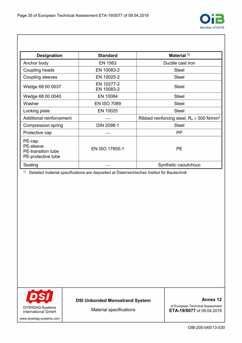
Page 35 of European Technical Assessment ETA-19/0077 of 09.04.2019
OIB-205-045/13-030
Designation Standard Material 1) Anchor body EN 1563 Ductile cast iron Coupling heads EN 10083-2 Steel Coupling sleeves EN 10025-2 Steel
Wedge 68 00 0037 EN 10277-2 EN 10083-2 Steel
Wedge 68 00 0040 EN 10084 Steel Washer EN ISO 7089 Steel Locking plate EN 10025 Steel Additional reinforcement ⎯ Ribbed reinforcing steel, Re 500 N/mm2 Compression spring DIN 2098-1 Steel Protective cap ⎯ PP
PE-cap PE-sleeve PE-transition tube PE-protective tube
EN ISO 17855-1 PE
Sealing ⎯ Synthetic caoutchouc 1) Detailed material specifications are deposited at Österreichisches Institut für Bautechnik
DYWIDAG-Systems International GmbH
www.dywidag-systems.com
DSI Unbonded Monostrand System
Material specifications
Annex 12 of European Technical Assessment
ETA-19/0077 of 09.04.2019

Page 36 of European Technical Assessment ETA-19/0077 of 09.04.2019
OIB-205-045/13-030
Free tendon layout, plate thickness 450 mm
AnchorageTwo-way tie,
plastic binder or equivalent,with protective tubes or equivalent
One-way tie, plastic binder or
equivalentTwo-way tie,plastic binder or equivalent, with protective tubes or equivalent
Anchorage
Two-way tie,plastic binder or equivalent,
with protective tubes or equivalent
≤ 3 000≤ 3 000 ≤ 000 ≤ 000300… 000
≤ 500
≤ 45
0
Dimensions in mm
1 Installing the bottom layer of reinforcement on spacers
2 Installing the spacers for the top layer of reinforcement taking account of tendon installation
3 Installing the tendon anchorages, fastening onto the framework
4 Placing the tendons on the lower reinforcement and on the spacers for tendon top layer
5 Cutting the PE-sheathing to the required length
6 Inserting the tendons through the anchorages
7 Placing protective tubes (e.g. cut PE-sheathings) in the region of the connections with the reinforcement for protection of the tendons
8 Installing the upper reinforcement
9 Lifting up and connecting the tendons to the upper reinforcement
10 Connecting the tendons with the lower reinforcement
11 Connecting and proofing the tendons with tape at the PE-sleeves of the anchors
12 Supervising the correct seat of the anchors and of the PE-sleeves before concreting
DYWIDAG-Systems International GmbH
www.dywidag-systems.com
DSI Unbonded Monostrand System
Tendon installation instructions Free tendon layout
Annex 13 of European Technical Assessment
ETA-19/0077 of 09.04.2019
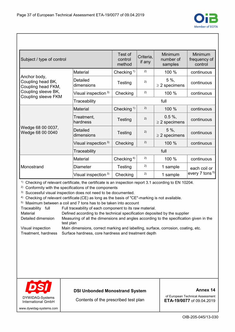
Page 37 of European Technical Assessment ETA-19/0077 of 09.04.2019
OIB-205-045/13-030
Subject / type of control Test of control method
Criteria, if any
Minimum number of samples
Minimum frequency of
control
Anchor body, Coupling head BK, Coupling head FKM, Coupling sleeve BK, Coupling sleeve FKM
Material Checking 1) 2) 100 % continuous
Detailed dimensions Testing 2) 5 %,
2 specimens continuous
Visual inspection 3) Checking 2) 100 % continuous
Traceability full
Wedge 68 00 0037, Wedge 68 00 0040
Material Checking 1) 2) 100 % continuous
Treatment, hardness Testing 2) 0.5 %,
2 specimens continuous
Detailed dimensions Testing 2) 5 %,
2 specimens continuous
Visual inspection 3) Checking 2) 100 % continuous
Traceability full
Monostrand
Material Checking 4) 2) 100 % continuous
Diameter Testing 2) 1 sample each coil or every 7 tons 5) Visual inspection 3) Checking 2) 1 sample
1) Checking of relevant certificate, the certificate is an inspection report 3.1 according to EN 10204. 2) Conformity with the specifications of the components 3) Successful visual inspection does not need to be documented. 4) Checking of relevant certificate (CE) as long as the basis of "CE"-marking is not available. 5) Maximum between a coil and 7 tons has to be taken into account Traceability full Full traceability of each component to its raw material. Material Defined according to the technical specification deposited by the supplier Detailed dimension Measuring of all the dimensions and angles according to the specification given in the
test plan Visual inspection Main dimensions, correct marking and labelling, surface, corrosion, coating, etc. Treatment, hardness Surface hardness, core hardness and treatment depth
DYWIDAG-Systems International GmbH
www.dywidag-systems.com
DSI Unbonded Monostrand System
Contents of the prescribed test plan
Annex 14 of European Technical Assessment
ETA-19/0077 of 09.04.2019

Page 38 of European Technical Assessment ETA-19/0077 of 09.04.2019
OIB-205-045/13-030
Subject / type of control Test of control method
Criteria, if any
Minimum number of samples 1)
Minimum frequency of control
Anchor body, Coupling head BK, Coupling head FKM, Coupling sleeve BK, Coupling sleeve FKM
Material Checking and
testing, hardness and chemical 2)
3) 1 1/year
Detailed dimensions Testing 3) 1 1/year
Visual inspection Testing 3) 1 1/year
Wedge 68 00 0037, Wedge 68 00 0040
Material Checking and
testing, hardness and chemical 2)
3) 2 1/year
Treatment, hardness
Checking and testing. hardness
profile 3) 2 1/year
Detailed dimensions Testing 3) 1 1/year
Main dimensions, surface hardness Testing 3) 5 1/year
Visual inspection Checking 3) 5 1/year
Single tensile element test According to
EAD 160004-00-0301, Annex C.7
9 1/year
1) If the kit comprises different kinds of anchor bodies and heads e.g. with different materials, different shape, different wedges, etc., then the number of samples are understood as per kind of anchor bodies and heads.
2) Testing of hardness and checking of chemical composition by means of an inspection report 3.1 according to EN 10204.
3) Conformity with the specifications of the components Material Defined according to the technical specification deposited by the ETA holder at the
Notified body Detailed dimension Measuring of all the dimensions and angles according to the specification given in the
test plan Visual inspection Main dimensions, correct marking and labelling, surface, corrosion, coating, etc. Treatment, hardness Surface hardness, core hardness, and treatment depth
DYWIDAG-Systems International GmbH
www.dywidag-systems.com
DSI Unbonded Monostrand System
Audit testing
Annex 15 of European Technical Assessment
ETA-19/0077 of 09.04.2019

Page 39 of European Technical Assessment ETA-19/0077 of 09.04.2019
OIB-205-045/13-030
European Assessment Document EAD 160004-00-0301 Post-Tensioning Kits for Prestressing of Structures
Standards Eurocode 2 Eurocode 2 – Design of concrete structures EN 206+A1 (11.2016) Concrete – Specification, performance, production and conformity EN 1563 (08.2018) Founding – Spheroidal graphite cast irons EN 10025-2+AC (06.2005) Hot rolled products of structural steels – Part 2: Technical delivery
conditions for non-alloy structural steels EN 10083-2+A1 (08.2006) Steels for quenching and tempering – Part 2: Technical delivery
conditions for non-alloy steels EN 10084 (04.2008) Case hardening steels – Technical delivery conditions EN 10204 (10.2004) Metallic products – Types of inspection documents EN 10277-2 (03.2008) Bright steel products – Technical delivery conditions – Part 2: Steels
for general engineering purposes EN ISO 7089 (06.2000) Plain washers – Normal series, Product grade A EN ISO 17855-1 (11.2014) Plastics – Polyethylene (PE) moulding and extrusion materials –
Part 1: Designation system and basis for specifications prEN 10138-3 (08.2009) Prestressing steels – Part 3: Strand CWA 14646 (01.2003) Requirements for the installation of post-tensioning kits for
prestressing of structures and qualification of the specialist company and its personnel
DIN 2098-1 (10.1968) Helical springs made from round wire – Cold coiled compression springs above and including 0.5 mm wire diameter
Other documents 98/456/EC Commission decision 98/456/EC of 3 July 1998 on the procedure for
attesting the conformity of construction products pursuant to Article 20 (2) of Council Directive 89/106/EEC as regards posttensioning kits for the prestressing of structures, Official Journal of the European Communities L 201 of 17 July 1998, p. 112
305/2011 R u ati ( U) 305/20 t ur p a ar iam t a t Council of 9 March 2011 laying down harmonised conditions for the marketing of construction products and repealing Council Directive 89/106/EEC, OJ L 88 of 4 April 2011, p. 5, amended by Commission D at R u ati ( U) 568/2014 of 18 February 2014, OJ L 157 of 27.05.2014, p. 76 and Commission Delegated R u ati ( U) 574/2014 of 21 February 2014, OJ L 159 of 28.05.2014, p. 41
568/2014 mmissi D at R u ati ( U) 568/2014 of 18 February 2014 amending Annex V t R u ati ( U) 305/2011 of the European Parliament and of the Council as regards the assessment and verification of constancy of performance of construction products, OJ L 157 of 27.05.2014, p. 76
DYWIDAG-Systems International GmbH
www.dywidag-systems.com
DSI Unbonded Monostrand System
Reference documents
Annex 16 of European Technical Assessment
ETA-19/0077 of 09.04.2019
A U S T R I A
A R G E N T I N A
A U S T R A L I A
B E L G I U M
B O S N I A A N D H E R Z E G O V I N A
B R A Z I L
C A N A D A
C H I L E
C O L O M B I A
C O S T A R I C A
C R O A T I A
C Z E C H R E P U B L I C
D E N M A R K
E G Y P T
E S T O N I A
F I N L A N D
F R A N C E
G E R M A N Y
G R E E C E
G U A T E M A L A
H O N D U R A S
H O N G K O N G
I N D O N E S I A
I T A L Y
J A P A N
K O R E A
L E B A N O N
L U X E M B O U R G
M A L A Y S I A
M E X I C O
N E T H E R L A N D S
N O R W A Y
O M A N
P A N A M A
P A R A G U A Y
P E R U
P O L A N D
P O R T U G A L
Q A T A R
S A U D I A R A B I A
S I N G A P O R E
S O U T H A F R I C A
S P A I N
S W E D E N
S W I T Z E R L A N D
T A I W A N
T H A I L A N D
T U R K E Y
U N I T E D A R A B E M I R A T E S
U N I T E D K I N G D O M
U R U G U A Y
U S A
V E N E Z U E L A
Belgium and LuxembourgDYWIDAG-Systems International N.V.Philipssite 5, bus 15Ubicenter, 3001 Leuven, BelgiumPhone +32-16-60 77 60Fax +32-16-60 77 66E-mail [email protected]/emea
FranceDSI-Artéon SAS Rue de la CrazZ.I. des Chartinières01120 Dagneux, FrancePhone +33-4-78 79 27 82Fax +33-4-78 79 01 56E-mail [email protected]
GermanyDYWIDAG-Systems International GmbHGermanenstrasse 886343 Koenigsbrunn, GermanyPhone +49-8231-96 07 0Fax +49-8231-96 07 10E-mail [email protected]
DYWIDAG-Systems International GmbHMax-Planck-Ring 140764 Langenfeld, GermanyPhone +49-2173-79 02 0Fax +49-2173-79 02 20E-mail [email protected]
DYWIDAG-Systems International GmbHSchuetzenstrasse 2014641 Nauen, GermanyPhone +49-3321-44 18 0Fax +49-3321-44 18 38E-mail [email protected]
DYWIDAG-Systems International GmbHNeuhofweg 585716 Unterschleissheim, GermanyPhone +49-89-30 90 50 100Fax +49-89-30 90 50 120E-mail [email protected]/emea
ItalyDYWIT S.P.A.Viale Europa 72 Strada A 7/920090 Cusago (MI), ItalyPhone +39-02-901 65 71Fax +39-02-901 65 73 01E-mail [email protected]
NetherlandsDYWIDAG-Systems International B.V.Veilingweg 25301 KM Zaltbommel, NetherlandsPhone +31-418-57 89 22Fax +31-418-51 30 12E-mail [email protected]
PolandDYWIDAG-Systems International Sp. z o.o. ul. Bojowników o Wolność i Demokrację 38/12141-506 Chorzów, PolandPhone +48-32-241 09 98Fax +48-32-241 09 28E-mail [email protected]
SpainDYWIDAG Sistemas Constructivos, S.A.Avd/de la Industria, 4Pol. Ind. la Cantuena28947 Fuenlabrada (Madrid), SpainPhone +34-91-642 20 72Fax +34-91-642 27 10E-mail [email protected]
United KingdomDYWIDAG-Systems International Ltd.Northfield RoadSoutham, WarwickshireCV47 0FG, Great BritainPhone +44-1926-81 39 80Fax +44-1926-81 38 17E-mail [email protected]
0450
9-1/
05.1
9-w
eb ca
www.dywidag-systems.com/emea