Embed Size (px)
Citation preview

Page 1
Section 509—Prestressing Concrete by Post Tensioning
509.1 General Description
This work consists of prestressing concrete by post-tensioning cast-in-place concrete. The work includes furnishing, placing,
and tensioning prestressing steel according to the Plan details and these Specifications.
509.1.01 Definitions
Working Force and Working Stress: The force and stress remaining in the prestressing steel after the following losses:
Creep and shrinkage of concrete
Elastic compression of concrete
Creep of steel
Loss in post-tensioned prestressing steel from the sequence of stressing
Friction and anchor set (see Subsection 509.3.05.J, “Post-Tension the Tendons,” steps 18 to 19)
Other losses peculiar to the method, technique, or system of prestressing (see Subsection 509.3.05.J, “Post-Tension
the Tendons,” step 21)
509.1.02 Related References
A. Standard Specifications
Section 501—Steel Structures
Section 535—Painting Structures
B. Referenced Documents
AASHTO Specifications for Highway Bridge, Article 9.16.1
AASHTO Specifications for Highway Bridge, Article 9.16.2
ASTM C 109
ASTM A 416
ASTM A 722
ASTM C 939
509.1.03 Submittals
A. Coupler Use and Location
The use and location of couplers in bars entering into the prestressing work is subject to the Engineer’s approval.
B. Alternate Stressing or Anchorage Block Drawings and Calculations
When using stressing or anchorage blocks not shown on the Plans, submit shop drawings and calculations for the blocks
to Bridge and Structural Design when submitting the prestressing system calculations and shop drawings.
C. Design Calculations
Submit design calculations for the proposed post-tensioning system to Bridge and Structural Design for Department
review and approval. Design calculations may be on letter size sheets.
Submit calculations for the size and spacing of the reinforcing around the ducts, as shown in Figure 1 (metric), to Bridge
and Structural Design. Include the following in the calculations:
Required jacking force and elongation of tendons during tensioning
Section 509—Prestressing Concrete by Post Tensioning
Page 2
Using the initial jacking force, design the reinforcing to prevent ducts from pulling out because of the effects of
web curvature and slope.
Stresses in anchorages and distribution plates
Ensure that the calculations account for reinforcing to prevent the peeling of anchorages from the top and bottom
slab. See Figure 2 (metric) for minimum reinforcing requirements for tying ducts to the deck reinforcing.
Stress-strain curves typical of the prestressing steel to be furnished
Seating losses
Temporary overstresses
Reinforcing in the concrete to resist tensioning loads
Determine bearing offsets and expansion joint gaps and adjust for construction sequence, prestress shortening, and
temperature.
Figure 1 (metric)
L = Length of anchor blister
*
A
A Tendon 3.0 ft (900 mm)
#4 (#13 M) bar, L + 6 ft. (1.8 m)
Transverse slab reinf.
Bend No. 4 (No. 13 M )
bars At 12 in. (300 mm) spacing around duct and
tie to longitudinal bar.

Section 509—Prestressing Concrete by Post Tensioning
Page 3
Figure 2 (metric)
D. Certificates of Compliance
The Department will accept certificates of compliance for cements to be used. The Department reserves the right,
however, to sample and test the cement before its use and at any time during the progress of the work.
E. Certified Mill Test Reports
Submit certified mill test reports for high tensile prestressing steel to the Project Engineer.
F. Shop Drawings
Submit Shop Drawings for review and approval according to Subsection 501.1.03.B, “Shop Drawings.” Place a title
block in the lower right-hand corner of the drawings that includes the following:
Project number
Sheet numbering for the Shop Drawings
Structure name
Contractor and fabricator names
Submit Shop Drawings on 23 in by 36 in (575 mm by 900 mm) sheets with a 1-1/2 in (38 mm) left margin and a ½ in
(13 mm) top, bottom, and right margins.
The Shop Drawings shall include the following:
1. Fully dimensional views showing all projections, recesses, notches, openings, blockouts, and pertinent design details
2. Details of mild steel reinforcing showing size, spacing, and location, including special reinforcing required as
determined by the design calculations but not shown on the Plans
3. Details of ducts for post-tensioning tendons showing size, type, and horizontal and vertical profiles

Section 509—Prestressing Concrete by Post Tensioning
Page 4
4. Details of duct supports, grout tubes, and vents showing size, type, and location
5. Details of the relative positions of reinforcing steel, ducts, and anchorages
6. Details of the anchorage systems for the proposed post-tensioning system
7. A table giving jacking sequence, jacking forces, and initial elongation of the tendons at each erection stage for post-
tensioning
8. Details and a complete description of the post-tensioning system to be used for permanent tendons
9. Details of the prestressing, including:
Method, sequence, and procedure for prestressing and securing tendons
Procedure for releasing tendons
Equipment supplier and type
Tendon size and properties
Anchorage plates and assemblies
10. Information on grouting, including:
Grout mix design
Method of mixing and placing the grout
Type and capacity of grouting equipment
11. Working drawings and bar schedules for each prestressing system
12. Details of reinforcing or coil ties under anchorage plates
13. Details for usage of high-strength steel bar (furnished by the bar manufacturer)
14. Friction factors used in the prestressing system of deformed bars
G. Ram Calibration Charts
Before using rams in the work, furnish the Engineer with a certified chart from the calibration for each ram.
H. Designs and Details of Distribution Reinforcing Steel
The Department plans for anchorages show only a minimum amount of distribution reinforcing steel.
Design and detail the reinforcement needed to prevent bursting, peeling, and splitting. Submit the designs and details to
the Engineer for review and approval.
I. Gauge Readings and Elongations
Keep a record of gauge pressures or readings and elongations at the end of each jacking operation and submit it to the
Engineer for review and approval.
509.2 Materials
Ensure that materials meet the requirements of the following Specifications:
Material Section
Steel Wire Strand 853
Structural Steel for Anchorage Devices, Distribution Plates, and Incidental Parts
Required to Be of Steel
501
Grout 509.3.02.C
Cement 830

Section 509—Prestressing Concrete by Post Tensioning
Page 5
Admixtures 831
Water 880
Do not use strands from more than one source within the same tensioning operation.
Strands that differ in size from ASTM A 416 are to be submitted for prior approval.
High strength steel bars shall meet ASTM A 722 Type II, and S1 through S3 supplemental requirements and have
manufacturers details for their use.
Ensure all bars within any member are of same grade.
Bar couplers and locations are to be approved prior to use and shall have tensile strength not less than manufacturers
minimum for strength of bar.
Allow the Department 60 calendar days before installing prestressing steel to test the steel and approve the materials
furnished.
Use the anchor devices and distribution plates recommended by the manufacturer of the prestressing system.
Have the Engineer approve grout for filling recesses or encasing anchoring devices. Use a type recommended by the
manufacturer for highly stressed steel.
509.2.01 Delivery, Storage, and Handling
A. Protect Prestressing Steel
Protect prestressing steel against physical damage, rust, and corrosion..
Reject all damaged, rusted, or corroded prestressing steel. See Subsection 509.3.06, “Quality Acceptance.”
B. Package Prestressing Steel
Package prestressing wire or strand in containers or shipping forms to protect steel from physical damage and corrosion
during shipping and storage. Comply with these packaging requirements:
1. Place a corrosion inhibitor to protect against rust and corrosion as follows:
a. Place the inhibitor in the package or form.
b. Incorporate the inhibitor in a carrier-type packaging material.
c. Apply the inhibitor directly to the steel.
Ensure that the corrosion inhibitor does not damage the steel, grout, or bond strength of the steel to the grout.
2. Immediately replace or restore to original condition damaged packaging or forms.
3. Clearly mark the shipping package or form with the following:
A statement that the package contains high-strength prestressing steel
Handling instructions
The type, kind, and amount, of corrosion inhibitor used, including the date placed, safety orders, and
instructions for use
C. Ducts
1. Place all prestressing steel tendons in openings or ducts.
2. Unless otherwise approved by the Engineer, use only rigid, galvanized, ferrous metal that is mortar tight for all
longitudinal prestressing steel ducts.
3. Fabricate the ducts with an inside area that is at least double the effective area of the prestressing steel in the duct.

Section 509—Prestressing Concrete by Post Tensioning
Page 6
a. Fabricate ducts that encase single high-strength prestressing steel bars with an inside diameter at least 3/8 in.
(10 mm) larger than the diameter of the bar to be used.
b. Use a minimum wall thickness of 0.030 in (0.75 mm).
4. Rigid ducts may be fabricated with either welded or interlocked seams. There is no need to galvanize the welded
seam or the transition couplings that connect the ducts to anchoring devices.
5. Weld transition couplings to the anchor plate.
6. Pre-bend all ducts that must be curved to match the roadway alignment and/or tendon profile. Shape the ducts
without crimping or flattening them.
509.3 Construction Requirements
509.3.01 Personnel
A. Representative of the Post-Tensioning System Supplier
If the Engineer requires, provide a representative of the post-tensioning system supplier at no additional cost to the
Department.
Provide a representative who:
Is skilled in using post-tensioning systems
Supervises or provides surveillance of the work
Provides information about the post-tensioning system to the Engineer as needed
509.3.02 Equipment
A. Prestressing Equipment
Provide the following equipment for construction and prestressing:
1. Tensioning Jacks
Use tensioning jacks equipped with the following:
Long enough stroke to perform stressing in a minimum number of strokes
Provide a positive means of marking each elongation increment where two or more strokes are required
Ports or windows to exam and measure tendon movement
Slow stress release capability to allow the jack to relax from overstress to the proper seating force
2. Tensioning Equipment
Use tension prestressing tendons equipped with the following:
Equipment that allows direct elongation measurement
Hydraulic ram that determines the tensioning force applied
Measure the tensioning force applied by the ram using either of the following gauges:
a. Gauge that measures either the internal hydraulic pressure in the ram or the force exerted by the ram
b. Spring-type dynamometer used with the tensioning force applied directly
Convert the readings from either of these gauges to actual tensioning forces using calibrated values from a
calibration chart.
Use gauges with a diameter of at least 6 in (150 mm) that allow accurate readings of load increments of one
percent of the total capacity of the ram used, not to exceed two percent of the tensioning force used.
3. Load Cell

Section 509—Prestressing Concrete by Post Tensioning
Page 7
Ensure that the range of the load cell does not use the lower 10 percent of the manufacturer’s rated capacity to
determine the jacking stress.
B. Sampling and Inspecting Prestressing Steel
The Department will identify, sample, test, and approve all prestressing steel as follows:
1. Identification
a. Assign a lot number to all strand and all bars of each size from each mill heat shipped to the jobsite.
b. Tag the lots so that each such lot can be positively identified at the job site.
c. Assign and tag each lot of anchorage assemblies and bar couplers.
d. The Engineer or Department inspector will reject all unidentified prestressing steel, couplers, or anchorage
assemblies received at the site, and any items without positive identification.
2. Sampling
a. Give to the Engineer samples from each size and each heat of prestressing bars and prestressing steel strand,
and from each lot of anchorage assemblies and bar couplers.
b. Submit with each sample of prestressing strand or bar the manufacturer’s certification stating the minimum
guaranteed ultimate tensile strength of the sample furnished.
c. Submit enough samples to make up two assembled test units from each heat, complete with end fittings and
anchoring devices. Test units shall be at least 8 ft. (2.4 m) long.
d. If the Engineer’s tests indicate the necessity of retests, submit twice the number of previous specimens without
cost to the Department. Identify the samples by heat number.
e. Submit samples to the Engineer in ample time to allow for testing, tabulating results, and, in case of
unsatisfactory findings, to call for and test substitute samples.
f. The Department will not pay the Contractor additional compensation because of the delay while waiting for
approval of the material furnished for testing.
3. Tendon Modulus of Elasticity
a. Submit to the Engineer for approval the apparatus and test methods you propose to use to determine the
modulus of elasticity.
b. Run bench tests on two samples of each size and type of longitudinal strand and/or wire tendon prior to
stressing the initial tendon.
c. Stress the tendon at an anchor assembly with the dead end consisting of a load cell.
d. Apply 80 percent of the ultimate tension to the test specimen in 10 increments and record the gage pressure,
elongation and load cell force for each increment..
e. Detension the test specimens back to 0 in 10 increments, and record the gage pressure, elongation, and load cell
force for each increment.
f. Submit the test data to the Engineer.
g. Re-evaluate and correct, as necessary, the theoretical elongations shown on the post-tensioning working
drawings based on the results of the tests.
h. Submit any revisions to the theoretical elongations to the Engineer.
i. After the initial testing, the Engineer may require five more tests. Space these tests evenly throughout the
duration of the contract.
4. In-Place Friction Test
a. Submit to the Engineer for approval the apparatus and test methods you propose to use to measure the in-place
friction.

Section 509—Prestressing Concrete by Post Tensioning
Page 8
b. After receiving approval for the apparatus and method, test the first draped continuity strand and/or wire tendon
in place of each size and type.
c. Apply 80 percent of the ultimate tension to the test specimen in 10 increments and record gage pressure
elongation and load cell force for each increment.
d. Detension the tendon back to 0 in 10 increments, and record the gage pressure, elongation, and load cell force
for each increment.
NOTE: You only need to run one friction test for each type and size of a tendon for the Project.
e. Submit the results of the tests (loss due to friction and modulus of elasticity) to the Engineer.
C. Grouting Equipment
Use grouting equipment capable of the following:
Continuously grouting the largest tendon on the Project in 20 minutes or less
Pumping the mixed grout according to the requirements of this Specification
Provide the following grouting equipment:
Mixer capable of continuous mechanical mixing and of producing a grout that is free of lumps and undispersed
cement
Accessory equipment that provides accurate solid and liquid measures to batch materials
Positive displacement pump able to produce an outlet pressure of at least 150 psi (1 MPa) gauge
Pump seals that do the following:
—Keep oil, air, or other foreign substance out of the grout
—Prevent loss of grout or water
Pressure gauge with a maximum full scale reading of 300 psi (2 MPa) installed at some point in the grout line
between the pump outlet and the duct inlet to establish grout pressure at the pump
Standby flushing equipment capable of pumping at 300 psi (2 MPa) gauge and flushing out partially-grouted
ducts
A different power source for the flushing equipment than the grouting equipment
Screen with 0.125 in (3 mm) maximum clear openings to screen the grout before it is introduced into the grout
pump
Hopper placed directly over the pump inlet
Attach the hopper to the pump inlet using a gravity feed.
Keep the hopper at least partially full of grout during the pumping operation to prevent air from being drawn
into the post-tensioning duct.
D. Rams
Twenty days before using rams and their gauges or reading devices in the work, have them calibrated by an approved
laboratory.
Recalibrate the equipment every three months during the work or when the Engineer observes erratic results. For each
calibration, furnish a calibration chart, certified by the laboratory, to the Engineer.
The Engineer may extend the 3-month interval if there are no performance changes. However, recalibrate at least every 6
months.

Section 509—Prestressing Concrete by Post Tensioning
Page 9
509.3.03 Preparation
A. Test Tendon Modulus of Elasticity
To determine the tendon elongations while stressing, bench test two samples of each size and type of longitudinal strand
and/or wire tendon using the following procedure:
1. Propose apparatus and methods used to perform these tests for approval by the Engineer.
2. Stress the tendon at an anchor assembly with the dead end consisting of a load cell.
3. Tension the specimen to 80% of ultimate in 10 increments.
4. Detension the specimen from 80% of ultimate to 0% in 10 increments.
5. Record the gage pressure, elongation, and load cell force for each increment. Provide this data for the Engineer.
6. Reevaluate the theoretical elongations shown on the post-tensioning working drawings using the results of the tests.
Correct the results as necessary.
7. Submit revisions to the Engineer for approval.
8. Perform five more tests after the initial testing (if required by the Engineer). Space these tests evenly throughout the
duration of the contract.
B. Test Friction
To accurately determine the friction loss in a strand and/or wire tendon, test, in place, the first draped continuity tendon
of each size and type using the same procedure described for the modulus of elasticity test. Only one friction test for each
type and size of a tendon is required for the project. Submit the results of the tests to the Engineer.
C. Test Anchorages
Before construction, test prestressing anchorage blocks of the type indicated in Figure 2 (metric) using the proposed
jacking system as follows:
1. Construct and test anchorage test blocks for the following:
Each different radius of bend of the duct into the anchorage
Each different number of strands per duct arrangement
2. If anchorages (reinforcing, anchorage geometry, anchor plate, and duct bend radius) are the same within a Project or
bridge, test only the anchorage with the largest jacking force.
3. Assemble a test block with these features:
Same concrete dimensions of the structure cross section at the points of anchorage in the proposed system
Tendon geometries, anchor plates, and anchorage reinforcing steel proposed for use in the structure
4. Place the tendons.
5. Stress the tendons to the full force required by the design using the proposed jacking system and stressing
procedures.
Anchorages are acceptable to the Department if no concrete cracks wider than 1/100 in (0.25 mm) develop within 3 days
under full force.
509.3.04 Fabrication
General Provisions 101 through 150.
509.3.05 Construction
A. Contractor Options
The Contractor may choose from these options when constructing the structure according to the Department plans:
1. Alternative Prestressing Systems
Section 509—Prestressing Concrete by Post Tensioning
Page 10
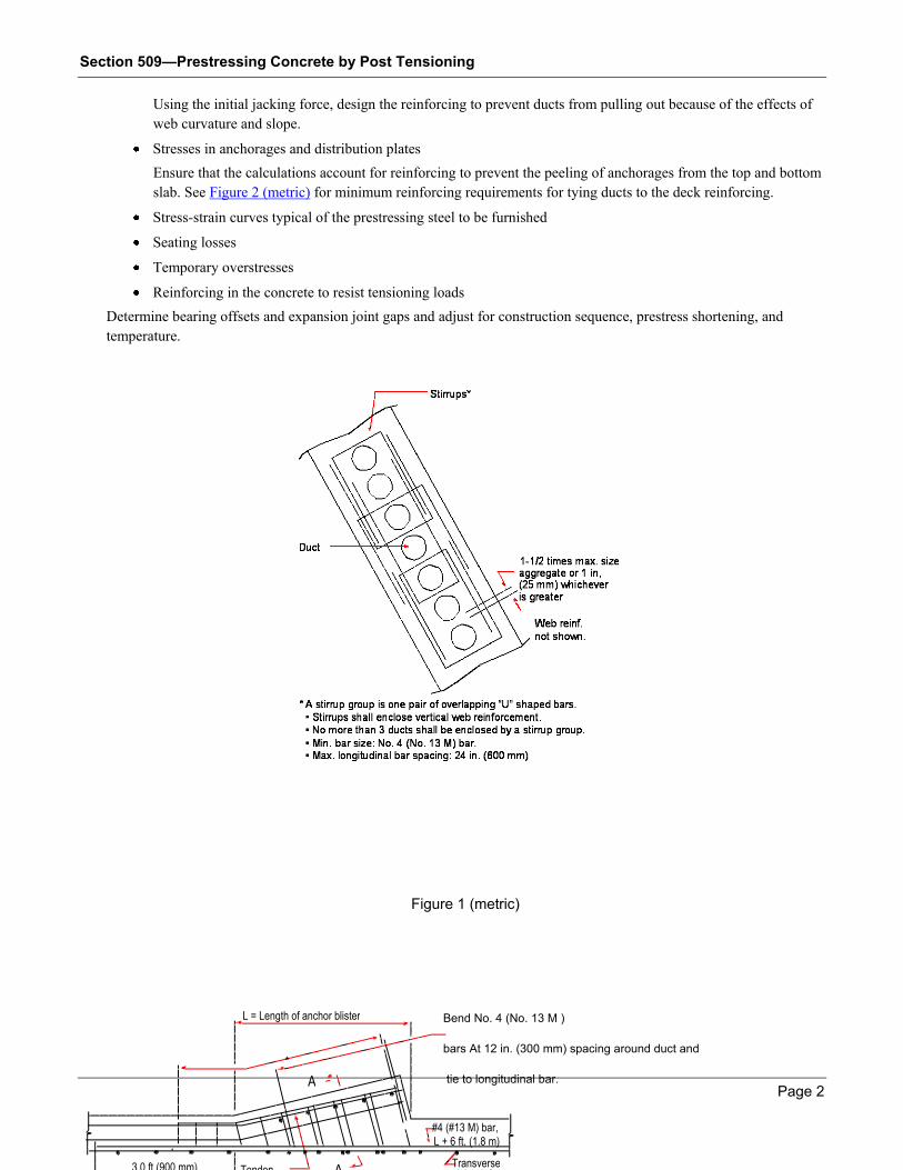
The Contractor may use post-tensioning systems other than those shown on the Plans. The alternative system may
use wires, bars, or strands anchored with friction grips or bearings.
Unless the Plans allow, do not use prestressing systems that incorporate dead-end anchorages.
Choose alternative systems that can be stressed from either end unless the construction staging does not allow room
to stress tendons from both ends. In this case, use anchorage systems with compression plates or fittings to seat
anchor wedges.
2. Alternative Stressing or Anchorage Blocks
Stressing or anchorage blocks for the structure may deviate from those shown on the Plans.
Alternate stressing or anchorage blocks must be located inside the box. Place the blocks in any of the following
locations:
At the juncture of the bottom of the top slab
At the juncture of the top of the bottom slab and the web walls
Within fillet areas in reinforced stressing blocks
In partial depth diaphragms
Permanent or temporary stressing blockouts are allowed in the top of the top slab when post-tensioning ducts do not
have a moisture-retaining low point.
B. Install the Ducts
Install ducts for prestressing steel as follows:
1. Support ducts at intervals of no more than 2 ft (600 mm).
The horizontal tolerance for longitudinal ducts in the top or bottom slab is plus or minus 1 in (25 mm). The vertical
tolerance for longitudinal ducts is plus or minus 1/4 in (6 mm).
2. Join rigid duct sections using positive metallic connections. Connect the sections carefully to prevent misaligning
the ducts at the joints.
3. Use waterproof tape at the connections.
4. Make duct splices so that the nose of the tendon being pushed into the duct goes from a male end into a female end.
This prevents tendons from catching on a duct end.
5. Stagger splices in ducts to prevent splices in the same location in a row of ducts. Stagger the splices to give a 3 ft
(900 mm) longitudinal spacing from row to row.
6. Carefully cut and deburr the ends of ducts.
7. Use ducts or anchorage assemblies with pipes or other connections as grout ports for injecting grout after the
prestressing. Ports are required at each tendon anchorage.
8. Place continuous-draped longitudinal ducts in the web in one vertical row at the center of the web.
9. Tie the ducts securely to the saddles, which shall hold the duct in position during concrete placement and hardening.
10. Ensure that the clear distance between the ducts is 1-1/2 times the maximum size aggregate in the concrete mix or 1
in (25 mm) whichever is greater.
11. Do not bundle ducts.
12. See Figure 3 (metric) below for an illustration of how to tie duct support saddles.
13. If needed, place ducts in the top or bottom slab in one of these ways:
Horizontally at the variable spacings
In closely and uniformly spaced groups
The minimum horizontal clear spacing between ducts must be 3 in (75 mm).

Section 509—Prestressing Concrete by Post Tensioning
Page 11
14. Install at least one more continuity duct than needed in each web throughout the length of the structure. This duct
will be used during blockage and excessive prestress losses during construction.
15. Position the ends of the additional ducts to use anchorage blocks if necessary.
16. Vent continuity ducts over each intermediate support.
Provide vents with a diameter of at least 1/2 in (13 mm) and made of either steel or polyethylene.
17. Provide vents at the low point of every duct to drain off water in the duct.
18. Connect vents to ducts using approved metallic structural fasteners.
19. Ensure that the vents are:
Mortar tight
Taped as necessary
Sealable
Capable of allowing grout to be injected through them
20. Immediately before installing the prestressing steel, demonstrate to the Engineer that ducts are unobstructed and free
of water and debris.
21. After installing ducts in the forms, keep the duct ends sealed to keep out water and debris.
22. After post-tensioning the steel, fill ducts with or without strands full of grout.
23. After the grout has set, remove the ends of the vents flush with the concrete surface.
Web longitudinal reinf. *Clearance may be larger. See bridge plans.
1 in. (25 mm) clearance.
1-1/2 times max. size aggregate or 1 in (25 mm), whichever is greater.
Inside face of web
3 in(75 mm) min. clearance
1-1/2 in. (38 mm)
min. clearance*
Outside face of web
typ. at each duct.
C L Web
Web thickness—2-1/2 in (63 mm)
Varies #3
(#10 M) bar
Radius of duct
1 in (25 mm) min. 1
5 i
n.
(37
5 m
m)
Tie duct support saddles to web vertical bars.
Space saddles at 24 in. (600 mm) maximum so
that vibrators can pass through to consolidate
Partial Web View

Section 509—Prestressing Concrete by Post Tensioning
Page 12
C. Install Reinforcing Steel
Fabricate reinforcing steel and place it according to the Plans and Shop Drawings.
Do not cut and remove reinforcing steel to align stressing ducts properly. Replace bars that cannot be fabricated to clear
the ducts with bars with an adequate lap length.
Where bars are extended by the use of couplers, the assembled units shall have a tensile strength of not less than the
manufacturer’s minimum guaranteed ultimate tensile strength of the bar.
Submit revised drawings indicating the proposed bar to the Engineer for review and approval.
D. Install Anchorages
Secure post-tensioned prestressing steel at the ends using permanent anchoring devices recommended by the prestressing
steel manufacturer and meeting the requirements herein..
Use anchoring devices that hold the prestressing steel at a load producing a stress of at least 95 percent of the guaranteed
minimum tensile strength of the prestressing steel.
E. Install Distribution Devices
Distribute the load from the anchoring device to the concrete using devices that conform to the following:
The final unit compressive stress on the concrete directly underneath the plate or assembly does not exceed 3,000
psi (20 MPa) or 0.9 (f”ci), whichever is less.
Bending stresses in the plates or assemblies induced by the pull of the prestressing steel do not exceed the yield
point of the material or distort the anchorage plate as determined by the Engineer when 100 percent of the load is
applied.
The Contractor may omit steel distribution plates or assemblies when furnishing large anchoring devices used with a
steel grill embedded in concrete to distribute the compressive stresses to the concrete.
Install distribution devices as follows:
1. Place steel distribution plates, if used, inside the end surface of the member.
2. Recess anchoring devices so that the ends of the prestressing steel and all of the anchoring devices are embedded in
concrete.

Section 509—Prestressing Concrete by Post Tensioning
Page 13
3. After post-tensioning and grouting the duct, clean foreign and loose material off the surfaces of the concrete.
Do not clean the concrete until the duct grouting operations are complete.
4. Fill anchoring device recesses with an approved, non-shrink grout.
5. Cover the anchoring devices and ends of the prestressing steel with at least 2 in (50 mm) of grout, unless the Plans
specify more.
F. Have the Engineer Inspect
Have the Engineer inspect and approve the placement of reinforcement, ducts, and anchorages before pouring concrete
into the forms.
G. Pour the Concrete
Pour concrete according to Section 500.
H. Install the Tendons
Install tendons in the ducts after pouring the top deck or when the Engineer approves.
Before installing the tendons, demonstrate to the Engineer that the ducts are unobstructed and free of water.
Install the tendon in the duct as approved by the Engineer.
I. Follow Weld Restrictions
The Engineer will not allow welds or welding equipment grounds on the forms or near the prestressing steel after the
steel has been installed.
J. Post-Tension the Tendons
Post-tension the tendons as follows:
1. Before post-tensioning tendons, ensure that the deck slab thickness and deck reinforcement cover comply with the
Plan requirements.
2. Unless otherwise noted on the Plans or approved by the Engineer, wait to prestress cast-in-place concrete until the
compressive strength of all the concrete placed reaches the required 28-day strength and the concrete is at least 14
days old.
If the Engineer approves, the Contractor may apply a portion of the prestressing force to a member with a concrete
strength less than the value shown on the Plans.
Even with this partial prestressing, the Contractor must successfully construct the members.
3. Conduct the tensioning process so that the applied tension and the elongation can be measured.
4. Tension the prestressing steel using hydraulic jacks.
5. Tension the prestressing tendons in continuous post-tensioned members by jacking at each end of the tendon.
Jacking of both ends does not need to be done simultaneously.
6. When approved by the Engineer and if shown on the Plans, tension bent cap tendons by jacking from one end only.
7. Tension the prestressing tendons in simple span post-tensioned members by jacking from one end only.
8. When tensioning from one end of the tendon only, tension half of the prestressing steel in each member from one
end and the other half from the opposite end of the span unless otherwise shown on the Plans.
9. Unless allowed on the Plans, do not use prestressing systems that incorporate dead-end anchorages.
10. Where construction staging does not allow room to stress tendons from both sides, use anchorage systems with
compression plates or fittings to seat anchor wedges.
11. Ensure that the prestressing steel force does not drop below the value shown on the Plans.
Section 509—Prestressing Concrete by Post Tensioning
Page 14
12. Ensure that the tendon force measured by gauge pressure is within 5 percent of the force calculated by elongation
movement.
13. If the measured elongation at the jacking stress varies more than 5 percent from the theoretical elongation, or if the
unbalanced force about the section center line exceeds 3 percent:
a. Check the entire operation and determine the error.
b. Correct the error to the Engineer’s satisfaction before proceeding with the work.
14. Do not allow the total force at each section to drop below the total prestressing force specified. However, the
prestressing force may vary plus or minus 5 percent per tendon.
15. Unless otherwise specified on the Plans, ensure that the average working stress in the prestressing steel does not
exceed 80 percent of the yield point stress of the prestressing steel.
16. To determine the amount of steel required, ensure that the maximum temporary tensile (jacking) stress in
prestressing steel does not exceed 80 percent of its specified minimum ultimate tensile strength unless the Plans
indicate a lower jacking stress.
17. Anchor the prestressing steel at stresses (initial stress) that will retain working forces at or higher than the minimum
values shown on the Plans or approved by the Engineer.
Do not allow the initial stress to exceed 70 percent of the specified minimum ultimate tensile strength of the
prestressing steel.
18. Check that the loss of elongation from anchor set agrees with the anticipated value used in the stress calculations.
a. Adjust measured Elongation to account for the actual measured anchor set.
b. Maintain 5 percent agreement between the elongation and the stressing force.
19. To compute the prestress losses from friction, use the formula in the AASHTO Specifications for Highway Bridge,
Article 9.16.1. The total friction losses at any section will be the sum of the effects for each tendon, depending on its
anchorage location for each tendon.
20. To compute other prestress losses, use the AASHTO Specifications for Highway Bridge, Article 9.16.2.
21. After stressing and anchoring tendons and after the Engineer approves, trim projecting tendons by sawing as shown
in the approved working drawings.
K. Mix the Grout
Grout for Prestressing Concrete Bridge Members: Grout for use with prestressing concrete bridge members includes a
mixture of Portland cement, water, and an approved expansive admixture, as follows:
Water—Use potable water or other water that meets the requirements of Subsection 880.2.01.
Portland cement—Use Portland cement that meets the requirements of Subsection 830.2.01. Standard usage is
Type II Portland cement, but the Engineer may allow Type I or III. The Engineer may require Type III for cold
weather grouting.
Submit to the Department certificates of compliance for the cements used. However, the Department reserves the
right to sample and test the cement before its use and at any time during the work.
Admixture—Use admixtures that meets the requirements of Subsection 831.2.02.A.
NOTE: Do not use sand in grout used for prestressing concrete bridge members.
1. Before grouting, select the material proportions based on the following:
Tests made on the grout
Documented experience with similar materials, equipment, and field conditions (weather, temperature, etc.).
2. Select admixtures used in Grout for Prestressing Concrete Members. If used and approved by the Engineer, use
admixtures that demonstrates low water content, good flowability, and minimum bleed.

Section 509—Prestressing Concrete by Post Tensioning
Page 15
You may use the following:
Either liquid or solid admixtures
Enough fine, aluminum powder to obtain 5 to 10 percent unrestrained expansion of the grout
Do not use the following:
Thixotropic additives without prior approval from the Engineer
Admixtures that have ingredients corrosive to steel or chemicals in quantities that may have a harmful effect
on cement
Admixtures with chloride ions in excess of 0.50 percent by weight of the admixture (assuming 1 lb (0.45 kg)
of admixture per 94 lbs (42.6 kg) each of cement), florides, sulphites, and nitrates
a. At least 30 days before using the admixture, submit to the Engineer at least 2 1/2 lbs (1 kg) of a proposed dry-
type admixture, or 1 quart (1 L) of a proposed liquid-type admixture.
b. Send with the sample a description of the content, recommended proportions to be used, and the manner and
sequence of adding to the mix.
3. Ensure that the water content is the minimum necessary for proper placement and does not exceed a water-cement
ratio of 0.45 (approximately 5 gal (19 L) of water per bag of cement).
4. Add the grout components to the mixer in the order listed or as required by the admixture manufacturer and mix the
dry materials in a mixer or clean, tight box until the mixture is a uniform consistency:
Water
Portland cement
Admixture
5. Mix the grout long enough to thoroughly blend it without excessively increasing the temperature or losing admixture
expansion properties.
6. Agitate the grout continuously until it is pumped.
7. Do not add water to increase grout flowability that has decreased because grout use is delayed.
The Engineer may determine grout pumpability according to the ASTM C 939. When using this method, efflux time for
the grout sample immediately after mixing must be at least 11 seconds.
L. Prepare Ducts for Grouting
Prepare the ducts for grouting by flushing the metal ducts as determined by the Engineer.
1. Use water to flush ducts that contains at least 0.1 lb/gal (10 g/L) of slaked lime (calcium hydroxide) or quicklime
(calcium oxide).
2. Use oil-free compressed air to blow out ducts.
M. Grout the Duct
Bond prestressing steel to the concrete by filling the space between the duct and the tendon with grout.
Grout the duct as follows:
1. Open the grout and vent openings.
2. Ensure that the pumping pressure at the tendon inlet does not exceed 250 psi (2 MPa) gauge.
3. Allow grout to flow from the first vent after the inlet pipe to remove residual flushing water or entrapped air.
4. Once water or air is removed, cap or otherwise close the vent. Close the remaining vents in sequence in the same
manner.
5. If the grouting pressure exceeds 250 psi (2 MPa) gauge, inject grout at a vent that has been or is ready to be capped.

Section 509—Prestressing Concrete by Post Tensioning
Page 16
a. Maintain a one-way grout flow while injecting.
b. Fit the vent used for injection with a positive shutoff.
c. If a one-way flow of grout cannot be maintained, immediately flush the grout out of the duct with water.
6. Pump grout through the duct and waste it continuously at the outlet pipe until the following happens:
No visible slugs of water or air are ejected.
The efflux time of the ejected grout is at least 11 seconds.
7. To ensure that the duct remains filled with grout:
a. Close the outlet.
b. Hold pumping pressure for an additional 15 seconds and then close the inlet.
c. Do not remove or open plugs, caps, or valves used to close off the outlet or inlet until the grout has set.
N. Place Rust Inhibitor
If prestressing and grouting are not completed within 10 consecutive days after installing steel strands in the ducts (or
within 30 days in the case of bars), use rust inhibitor in the ducts.
Prestressing steel installed but not grouted within the specified number of consecutive days is subject to the limits in
Subsection 509.3.06.C, “Rust Limits.” If the Engineer directs, remove rejected tendons at no cost to the Department.
Do not reuse prestressing steel that has been detensioned. Replace detensioned prestressing steel.
O. Paint Steel Parts
Paint steel parts exposed in the completed structure as follows:
1. Field clean the parts according to Subsection 535.3.03.A, “Clean New Steel Structures.”
2. Field paint the parts according to System IV of Section 535.
3. Paint the ends of strands according to System IV of Section 535.
509.3.06 Quality Acceptance
A. For Prestressing Concrete Bridge Members
Use grout that has a minimum compressive strength of 3,000 psi (20 MPa) at 28 days, as determined by ASTM C 109.
B. Tendon Standards
Individual wires in a 7-wire strand or wires in a parallel wire tendon may fail if the total area of wire failure is not more
than 2 percent of the total cross-sectional area of tendons in any member.
Failure of an entire strand will be subject to structural review.
C. Rust Limits
Prestressing steel will be rejected when:
The opened package (pak) of prestressing steel has an even coating of rust or rust film over the entire pak.
One or more wires in a strand are rusted throughout their length.
A length of strand or bar contains clinging rust, pits, or other faults.
Prestressing steel will be accepted when:
Rust film can be removed by light rubbing, leaving light streaks or spots but no pitting.
Rust forms during the 10 consecutive days (or 30 consecutive days for bars) between the installation of steel in
the ducts and the prestressing and grouting.

Section 509—Prestressing Concrete by Post Tensioning
Page 17
509.3.07 Contractor Warranty and Maintenance
General Provisions 101 through 150.
509.4 Measurement
Prestressing cast-in-place concrete is measured as an accepted lump quantity, complete in place.
The Contract Lump Sum price paid for prestressing cast-in-place concrete will be full compensation for the following:
Furnishing labor, materials, tools, equipment, and incidentals
Doing Work to furnish, place, and tension the prestressing steel in cast-in-place concrete structures complete in
place and as specified on the Plans and in these Specifications
509.4.01 Limits
A. Tests
Tests performed by the Contractor will not be paid for separately but will be considered incidental to the project.
No additional payment will be made for testing prestressing anchorage blocks. Costs associated with performing the test,
including materials, equipment, and labor, will be included in the bid price for prestressing.
B. Additional Compensation
No additional compensation will be made for the following:
Furnishing and placing additional deformed bar reinforcing steel, ducts, anchoring devices, saddles, distribution
plates or assemblies, and incidental parts
Furnishing samples for testing
Performing testing
Grouting recesses
Pressure grouting ducts
Full compensation will be included in the Contract Lump Sum price paid for prestressing cast-in-place concrete.
509.5 Payment
Payment will be made under:
Item No. 509 Prestressing cast-in-place concrete, Bridge No._____ Per lump sum
509.5.01 Adjustments
General Provisions 101 through 150.