Embed Size (px)
Citation preview
PRESENTED BY:S.Neelakandan,
R.S.Karthikeyan,P.Ashok,
GUIDED BY: V.S.Venkatesan,Prof. S.Vijayaraj Final Year Mechanical,(HOD/MECH) A.V.C College of Engineering.
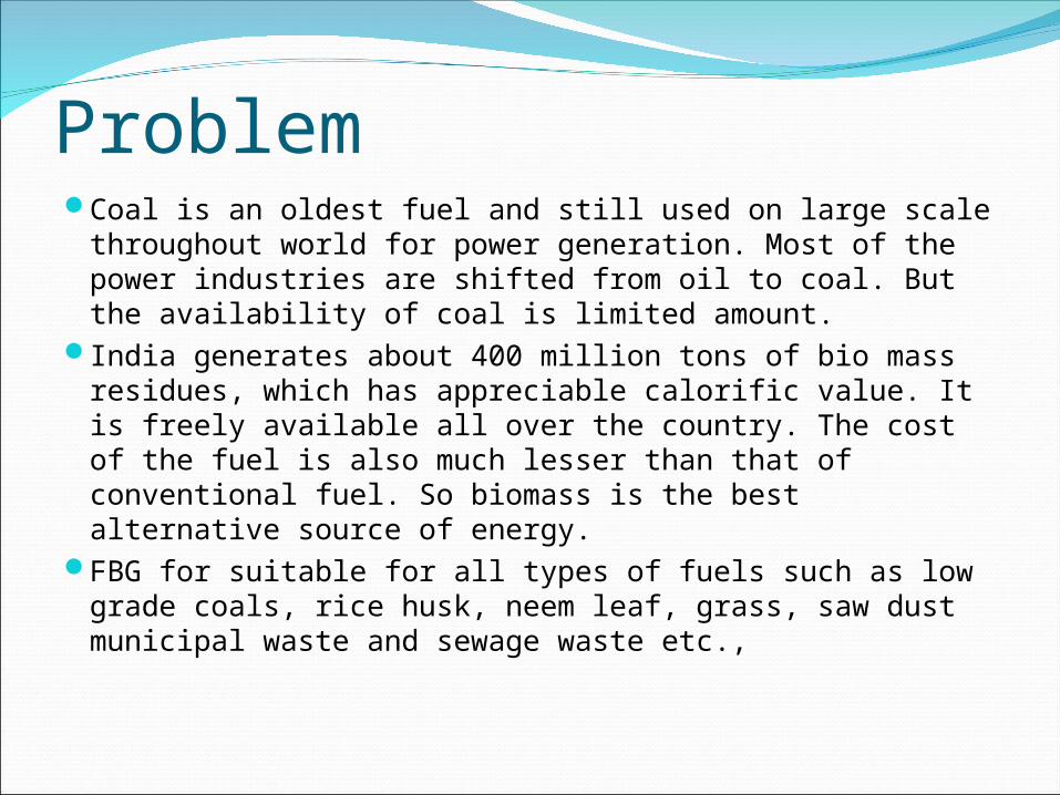
Problem Coal is an oldest fuel and still used on large scale throughout
world for power generation. Most of the power industries are shifted from oil to coal. But the availability of coal is limited amount.
India generates about 400 million tons of bio mass residues, which has appreciable calorific value. It is freely available all over the country. The cost of the fuel is also much lesser than that of conventional fuel. So biomass is the best alternative source of energy.
FBG for suitable for all types of fuels such as low grade coals, rice husk, neem leaf, grass, saw dust municipal waste and sewage waste etc.,
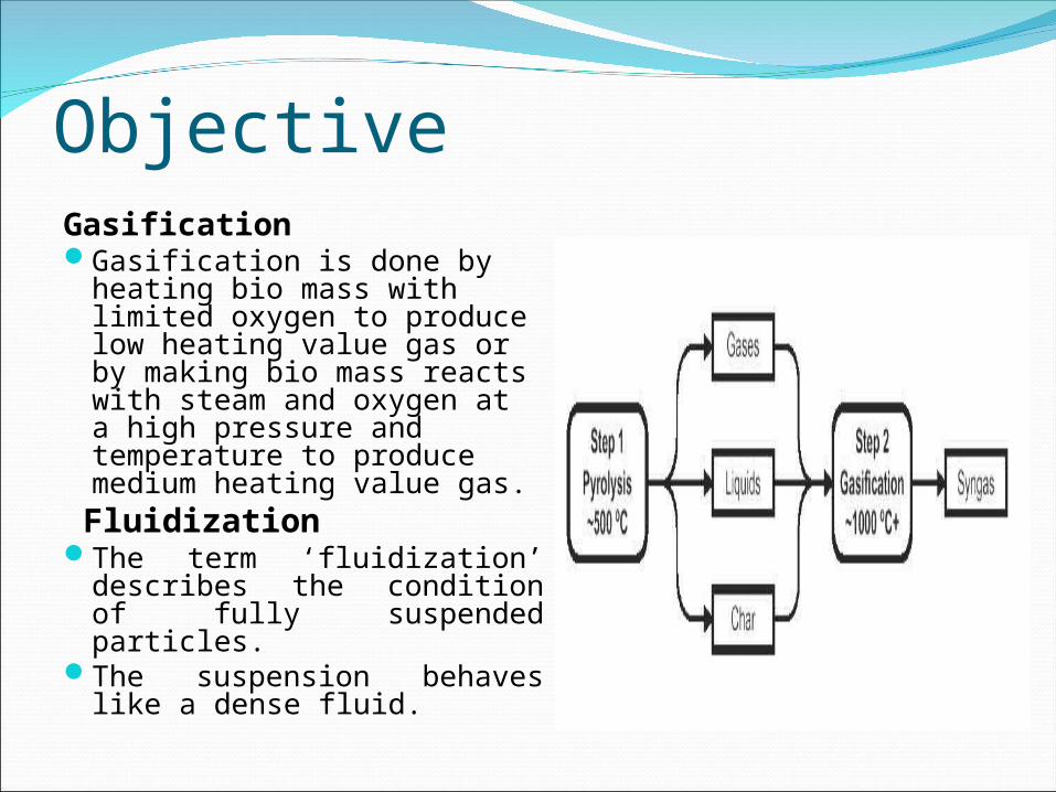
ObjectiveGasificationGasification is done by heating
bio mass with limited oxygen to produce low heating value gas or by making bio mass reacts with steam and oxygen at a high pressure and temperature to produce medium heating value gas.
FluidizationThe term ‘fluidization’ describes
the condition of fully suspended particles.
The suspension behaves like a dense fluid.
ApplicationIn general, it is probably acceptable to say that
gasification systems could be used in nearly every application in which natural gas, oil, or pulverized coal are currently being used.
The gases can be used to fire cement or lime kilns, rotary dryers, wood veneer dryers or dry kilns, air heaters, steam boilers, and turbine or diesel generator sets.
Possibly, the simplest application for a fluidized bed gasifier is to fire or co-fire an existing steam boiler. This presents the most likely opportunity where the steam demand is located adjacent to a fuel source.

MethodologyGASIFICATIONThe production of generator gas (producer gas) is called
gasification, is partial combustion of solid fuel (biomass) and takes place at temperature of about 1000˚C. The reactor is called a gasifier.
The product of the process of gasification is gas , the main constituents of which are CO,CO2,H2,CH4,higher hydrocarbons, N2 and impurities.
GASIFICATION PRINCIPLEGasification is the thermal decomposition of organic matter in
an oxygen deficient atmosphere producing a gas composition containing combustible gases, liquids and tars and charcoal with air or inert fluidizing gases.
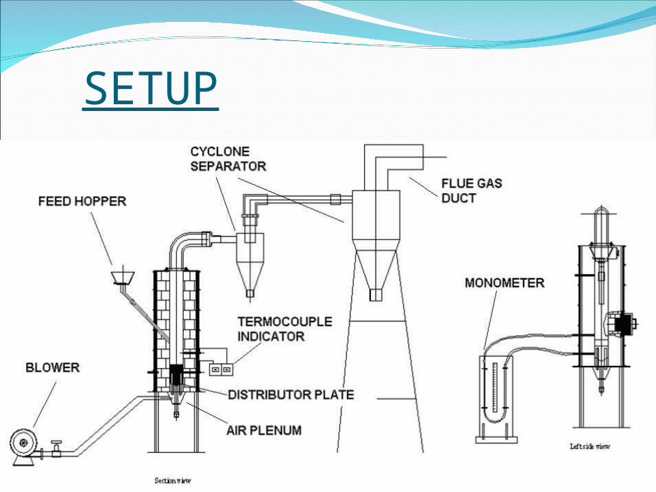
SETUP
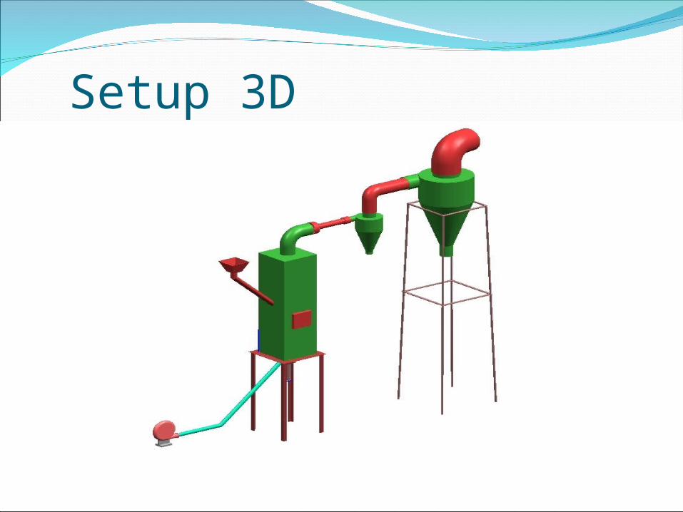
Setup 3D

DESIGN CALCULATIONFUEL FEED RATEStochiometric Air Req = 100/23[8/3*C+8H2+S-O2]
= 4.821
� 5 kg/kg of fuel
CYCLONE SEPARATOR
Separator 1: Separator 2 :
Inlet area, A = π /4*d2 (d=0.0508 ) Inlet area, A = π /4*d2 (d= 0.1016 )
= 2.027*10-3 m2 = 8.17*10-3 m2
Body Dia = 4D = 0.2032 m Body Dia = 4D = 0.4064 m
Body Height = 2.33D = 0.1184 m Body Height = 2.33D = 0.2367 m
Cone Height = 4D = 0.2032 m Cone Height = 4D = 0.4064 m
Clean Gas Outlet = 2D = 0.1016 m Clean Gas Outlet = 2D = 0.2032 m
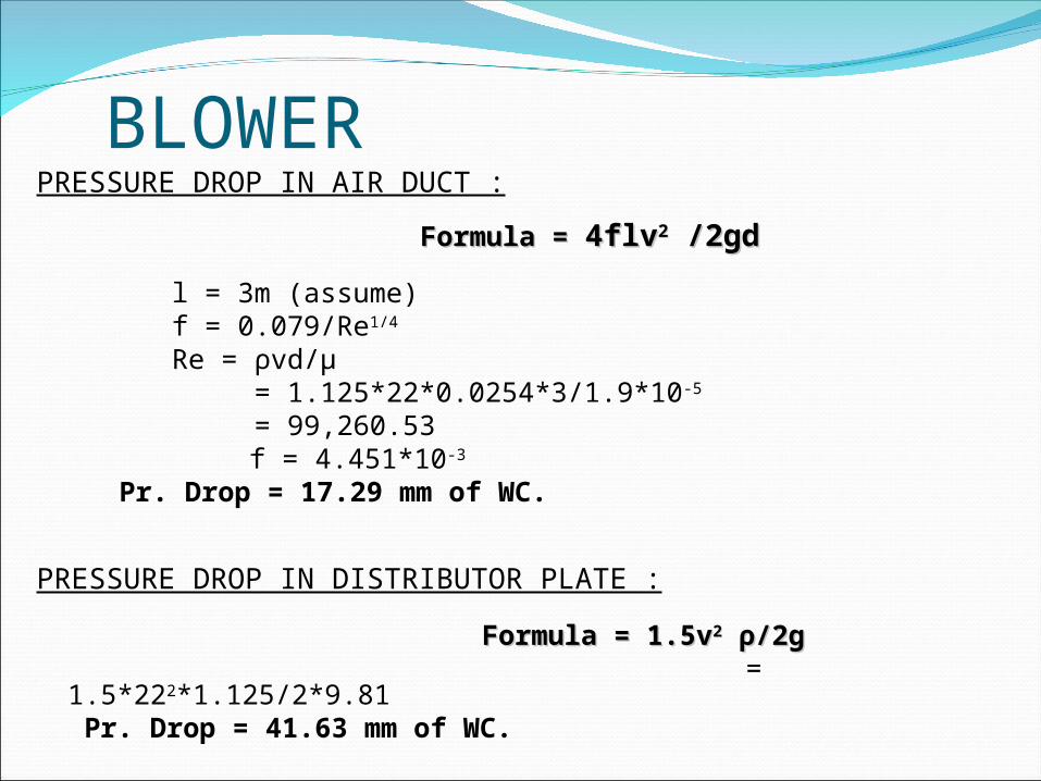
BLOWERPRESSURE DROP IN AIR DUCT :
Formula = Formula = 4flv4flv22 /2gd /2gd
l = 3m (assume)f = 0.079/Re1/4
Re = ρvd/µ = 1.125*22*0.0254*3/1.9*10-5
= 99,260.53 f = 4.451*10-3
Pr. Drop = 17.29 mm of WC.
PRESSURE DROP IN DISTRIBUTOR PLATE :
Formula = 1.5vFormula = 1.5v22 ρρ/2g/2g = 1.5*222*1.125/2*9.81
Pr. Drop = 41.63 mm of WC.
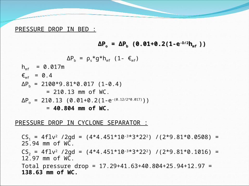
PRESSURE DROP IN BED :
∆∆PPoo = ∆P = ∆Pbb (0.01+0.2(1-e (0.01+0.2(1-e-D/2-D/2hhmf mf ))))
∆Pb = ρs*g*hmf (1- €mf)
hmf = 0.017m
€mf = 0.4
∆Pb = 2100*9.81*0.017 (1-0.4) = 210.13 mm of WC.
∆Po = 210.13 (0.01+0.2(1-e-(0.12/2*0.017))) = 40.804 mm of WC.
PRESSURE DROP IN CYCLONE SEPARATOR :
CS1 = 4flv2 /2gd = (4*4.451*10-3*3*222) /(2*9.81*0.0508) = 25.94 mm of WC.
CS2 = 4flv2 /2gd = (4*4.451*10-3*3*222) /(2*9.81*0.1016) = 12.97 mm of WC.Total pressure drop = 17.29+41.63+40.804+25.94+12.97 = 138.63 mm of WC.

PlanningModifications completed in the reactorIncreasing the inlet diameter of the reactor to 3”Increasing the blower Capacity to 1HP
Fuel PreparationCollection of Bio wastes like Paddy Straw & Mahua
Leaves.Drying the wastes.Chopping of fuel for feeding the reactor.

PROXIMATE ANALYSISIt is used to
tell the behavior of fuel inside the reactor.
It measures the Moisture and Ash content of the fuel.
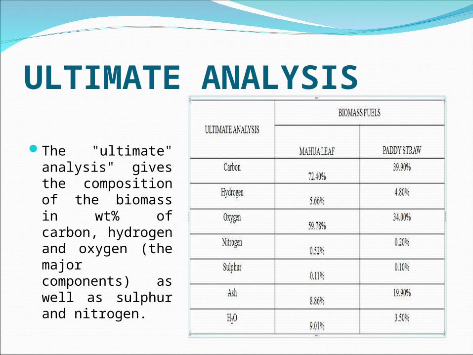
ULTIMATE ANALYSIS
The "ultimate" analysis" gives the composition of the biomass in wt% of carbon, hydrogen and oxygen (the major components) as well as sulphur and nitrogen.
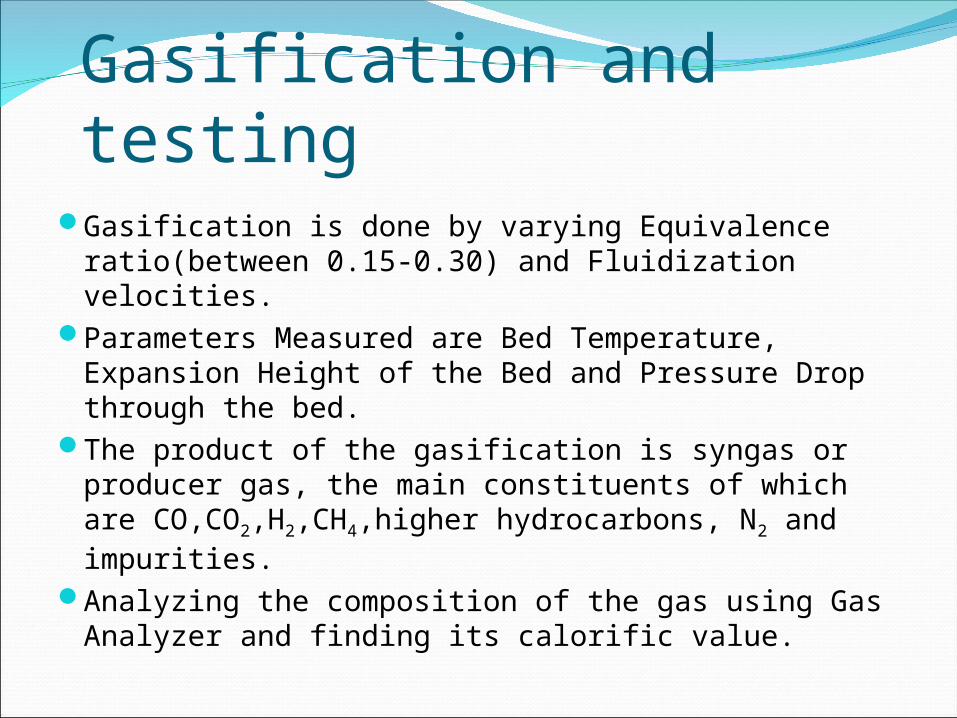
Gasification and testingGasification is done by varying Equivalence ratio(between
0.15-0.30) and Fluidization velocities.Parameters Measured are Bed Temperature, Expansion Height
of the Bed and Pressure Drop through the bed.The product of the gasification is syngas or producer gas, the
main constituents of which are CO,CO2,H2,CH4,higher hydrocarbons, N2 and impurities.
Analyzing the composition of the gas using Gas Analyzer and finding its calorific value.
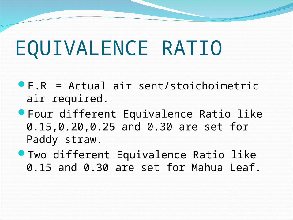
EQUIVALENCE RATIO
E.R = Actual air sent/stoichoimetric air required.
Four different Equivalence Ratio like 0.15,0.20,0.25 and 0.30 are set for Paddy straw.
Two different Equivalence Ratio like 0.15 and 0.30 are set for Mahua Leaf.