Embed Size (px)
Citation preview

WIFO-Anema B.V. Hegebeintumerdyk 37 – 9172 GP Ferwert – Holland Telefoon (0031) 518411318 – Telefax (0031) 518411563 www.wifo.nl – email: [email protected]
Manual and safety instructions
HOD/HOD-F/HOD-Z/HOD-ZF/HO/HOD-V Hydraulic loading bucket
GB
HOD fork mounted HOD-Z fork mounted HO fork mounted
HOD-F fork carriage mounted HOD-V HOD-ZF fork carriage mounted


1
English
Table of contents
1. TO THE USER ...................................................................................................................................................................... 2
1.1 INTRODUCTION ...................................................................................................................................................................... 21.2 SAFETY PRECAUTIONS AND WARNINGS ........................................................................................................................................ 3
1.2.1 Safety precautions .................................................................................................................................................... 31.2.2 Safety stickers and warning signs ............................................................................................................................. 61.2.3 Location of the safety stickers on the machine ......................................................................................................... 6
1.3 PURPOSE OF USE .................................................................................................................................................................... 71.4 LIABILITY ............................................................................................................................................................................... 81.5 WARRANTY ........................................................................................................................................................................... 8
2. TECHNICAL DATA ............................................................................................................................................................... 9
2.1 GENERAL TECHNICAL DATA ....................................................................................................................................................... 92.2 FORK MOUNTED HOD ........................................................................................................................................................... 11
2.2.1 Parts list .................................................................................................................................................................. 112.3 FORK CARRIAGE MOUNTED HOD-F .......................................................................................................................................... 12
2.3.1 Parts list .................................................................................................................................................................. 122.4 FORK MOUNTED HOD-Z ....................................................................................................................................................... 13
2.4.1 Parts list .................................................................................................................................................................. 132.5 FORK CARRIAGE MOUNTED HOD-ZF ........................................................................................................................................ 14
2.5.1 Parts list .................................................................................................................................................................. 142.6 FORK MOUNTED HO ............................................................................................................................................................. 15
2.6.1 Parts list .................................................................................................................................................................. 152.7 HOD-V FOR TELESCOPIC FORKLIFT TRUCKS, FRONT LOADERS, MOBILE SHOVELS ................................................................................ 16
2.7.1 Parts list .................................................................................................................................................................. 162.7.2 Commissioning fork mounted hydraulic bucket ...................................................................................................... 172.7.3 Commissioning fork carrier mounted hydraulic bucket .......................................................................................... 172.7.4 Commissioning of bucket connected to telescopic forklift, front loader or mobile shovel ..................................... 18
2.8 REPLACEMENT COMPONENTS .................................................................................................................................................. 19
3. MAINTENANCE AND TROUBLESHOOTING ........................................................................................................................ 20
3.1 PREVENTIVE MAINTENANCE AND LUBRICATION ........................................................................................................................... 203.2 TROUBLESHOOTING .............................................................................................................................................................. 213.3 WORK TO BE CARRIED OUT BY A COMPETENT MECHANIC .............................................................................................................. 21
3.3.1 Instructions for replacement of the blade and/or wearing strips ........................................................................... 21

2
1. To the user
1.1 Introduction
The aim of this manual is to inform users about the commissioning, use and maintenance of their new WIFO hydraulic loading bucket. Also included in this manual are a number of safety instructions to create a safe working environment.
At WIFO-Anema B.V. we aim to continuously improve our products. WIFO-Anema B.V. reserve the right to introduce any changes and improvements deemed necessary without prior notice.
Please read the manual thoroughly and observe the safety procedures before putting the unit into operation. Contact your dealer for any further questions or concerns you may have.
We trust your WIFO hydraulic loading bucket will provide many years of useful service.
Keep this manual in a safe place for future reference!
WIFO-Anema B.V.
Dealer:
ATTENTION: Carefully read this manual before you put the machine into operation and act upon all directions that are given. This is to guarantee its safe, trouble-free operation.

3
This symbol is used for all important actions that should not be carried out under any circumstances. Carefully observe these prohibitions.
1.2 Safety precautions and warnings
Please read this manual before you put the machine into operation for the first time, and observe the safety instructions at all times. The most important instructions are marked with a symbol.
Any person in charge of the commencement of operation, the operation itself or the maintenance of the machine is urged to carefully read and observe the following instructions.
1.2.1 Safety precautions The following safety instructions apply to all types of WIFO hydraulic loading buckets.
Do not allow anyone to hitch a ride.
Persons must not stand below the raised bucket. Remember that items may fall from the bucket.
This symbol is used for all important safety instructions throughout this manual. Carefully observe the instructions and be very cautious.

4
The loading bucket should be tipped back when transporting loads, in order to prevent the load falling out. Loads should be carried with the bucket in the lowest possible position to provide maximum stability to the lifting vehicle.
When tipping the loading bucket, ensure adequate clearance between the bucket and the ground in order to prevent damage to the loading bucket.
During loading, the bucket must be kept horizontal or tilted a little forwards (max. 15°). Ensure that the bucket blade does not become trapped under or behind raised edges, rails etc. in order to avoid damage.
In order to prevent damage to the cylinder, a standard fork lift truck must not drive forwards, and a tractor fitted with a lifting mast must not reverse, while the loading bucket is in the forward (tipped) position, with the blade of the bucket on the ground.
5
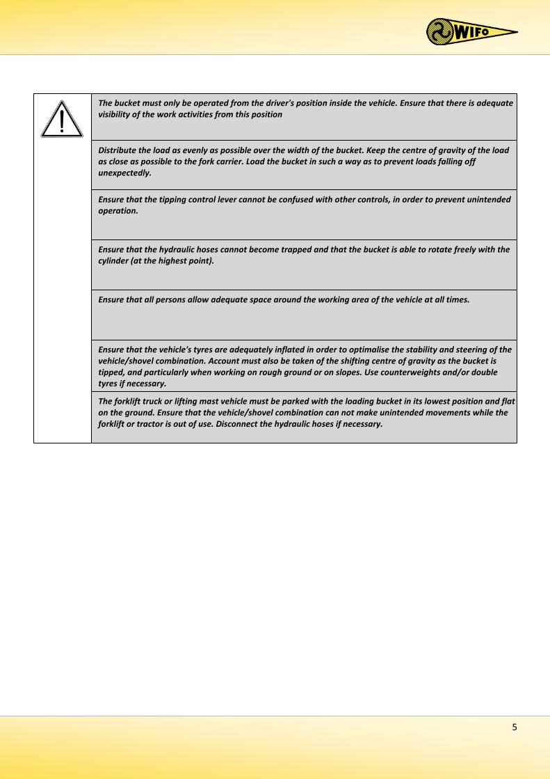
Ensure that the tipping control lever cannot be confused with other controls, in order to prevent unintended operation.
Ensure that the hydraulic hoses cannot become trapped and that the bucket is able to rotate freely with the cylinder (at the highest point).
The bucket must only be operated from the driver's position inside the vehicle. Ensure that there is adequate visibility of the work activities from this position
Ensure that the vehicle's tyres are adequately inflated in order to optimalise the stability and steering of the vehicle/shovel combination. Account must also be taken of the shifting centre of gravity as the bucket is tipped, and particularly when working on rough ground or on slopes. Use counterweights and/or double tyres if necessary. The forklift truck or lifting mast vehicle must be parked with the loading bucket in its lowest position and flat on the ground. Ensure that the vehicle/shovel combination can not make unintended movements while the forklift or tractor is out of use. Disconnect the hydraulic hoses if necessary.
Distribute the load as evenly as possible over the width of the bucket. Keep the centre of gravity of the load as close as possible to the fork carrier. Load the bucket in such a way as to prevent loads falling off unexpectedly.
Ensure that all persons allow adequate space around the working area of the vehicle at all times.
6
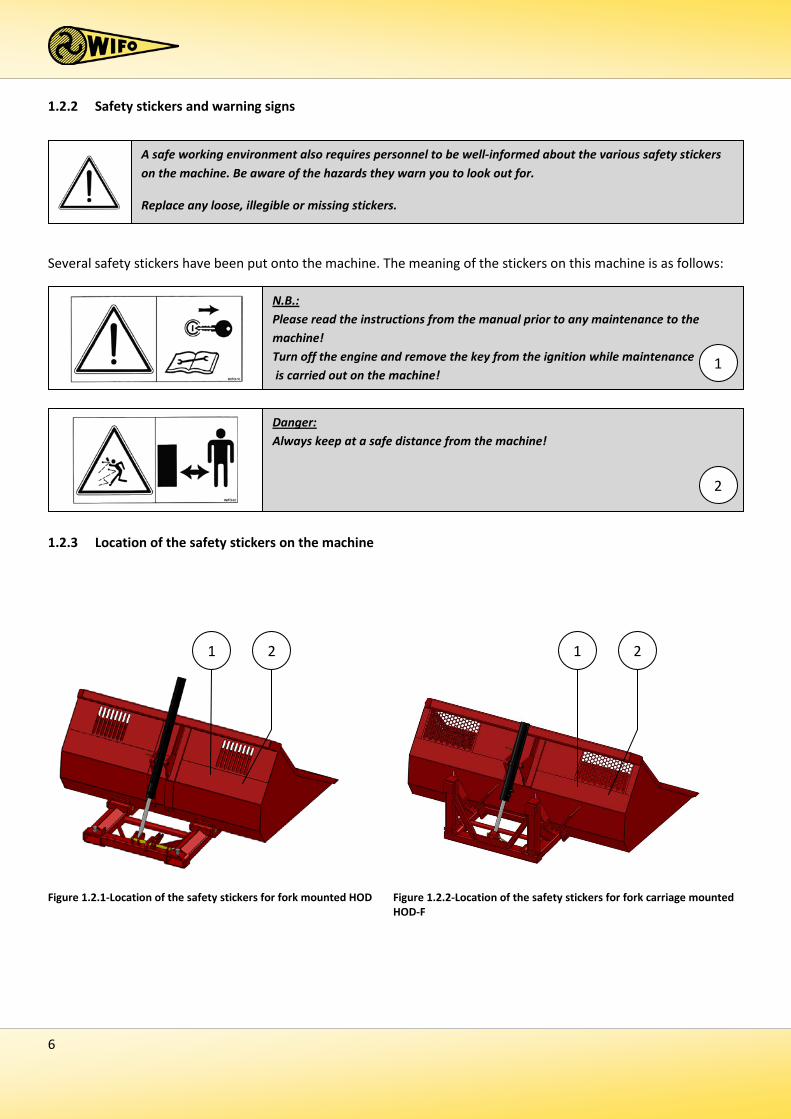
1.2.2 Safety stickers and warning signs
Several safety stickers have been put onto the machine. The meaning of the stickers on this machine is as follows:
1.2.3 Location of the safety stickers on the machine
A safe working environment also requires personnel to be well-informed about the various safety stickers on the machine. Be aware of the hazards they warn you to look out for.
Replace any loose, illegible or missing stickers.
Figure 1.2.1-Location of the safety stickers for fork mounted HOD
N.B.: Please read the instructions from the manual prior to any maintenance to the machine! Turn off the engine and remove the key from the ignition while maintenance is carried out on the machine!
1
1 2 1 2
Figure 1.2.2-Location of the safety stickers for fork carriage mounted HOD-F
Danger: Always keep at a safe distance from the machine!
2

7
1.3 Purpose of use
The special side plates, the rounded sides and the vision gratings make WIFO HO, HOD, HOD-V and HOD-Z hydraulic high visibility loading buckets particularly suitable for loading and transporting products sensitive to damage, such as eating or seed potatoes, onions, flower bulbs etc.
The hydraulic bucket must in no circumstances be used for the carriage of persons!
NOTE: The capacity of the forklift truck or lifting mast must exceed the total mass of the bucket and load. The forklift truck or lifting mast must be equipped with a double action hydraulic connection at the fork carrier, as a minimum.
Figure 1.2.3-Location of the safety stickers for fork mounted HOD-Z
Figure 1.2.5-Location of the safety stickers for fork mounted HO
1 2 1 2
1 2 1 2
Figure 1.2.4-Location of the safety stickers for fork carriage mounted HOD-ZF
Figure 1.2.6-Location of the safety stickers for HOD-V (telescopic forklift, etc)
8
1.4 Liability
Any person working with or on the machine must have read this manual. The machine is to be used for its intended purpose only. Included in the intended purpose are, among other things:
1. Work must be carried out in accordance with the directions and within the functional restrictions (e.g. maximum hydraulic working pressure) as outlined in the regulations. Use only sound and appropriate tools.
2. Electric/electronic equipment and accessories (e.g. cables) must be treated in accordance with the general accepted policy for using non-waterproof portable electric and electronic equipment, such as:
a) Storing and keeping in a clean, dry environment away from rodents and the like; and b) Protecting the equipment against severe, uncushioned shocks and water (precipitation).
3. Use only original or compatible spare parts. Such parts must be assembled as directed (e.g. by observing the
recommended tightening moments). Spare parts (as well as lubricants) are considered compatible only if explicitly approved by WIFO or in the event that the customer is able to prove they possess the required properties for the purpose(s) they are used.
4. Use only lubricants that meet the specifications as described in the directions. 5. Always observe the local regulations in terms of accident prevention, safety, traffic and transport. 6. Only trained personnel with knowledge of the possible hazards have permission to work with/on the
machine. 7. WIFO-Anema B.V. will assume no liability in any shape or form for losses or damage caused following
modifications to the machine, which have not been explicitly approved by WIFO.
1.5 Warranty
WIFO-Anema B.V. guarantees the soundness of its products in terms of materials used and/or structural defects. However, in any event this warranty is limited to the free-of-charge replacement or repairs of the defect product, or part thereof. WIFO-Anema B.V. assumes no liability for any loss or damage arising from faulty deliveries and/or the breakdown of purchased goods before the warranty period has expired. The warranty period for this product is twelve months.
Noncompliance with the rules and directions from this manual will be considered as serious negligence, for the consequences of which WIFO-Anema B.V. accepts no liability whatsoever. In such cases, the user will bear the full risk of his actions.
WIFO-Anema B.V. is continuously working on the improvement of its products. For that reason, WIFO-Anema B.V. reserves the right to introduce any changes and improvements deemed necessary without prior notice. However, it does not imply an obligation to make any such changes or improvements to machines bought by customers in the past.
9
2. Technical data
2.1 General technical data
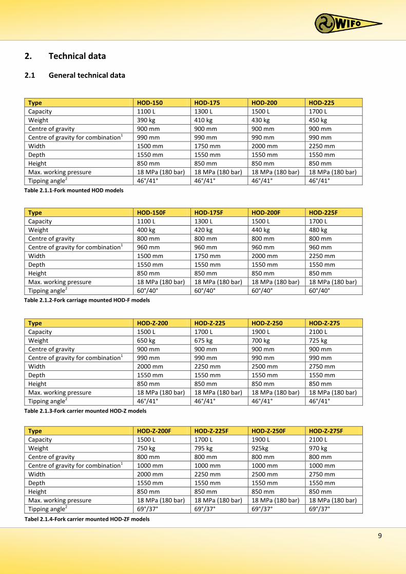
Type HOD-150 HOD-175 HOD-200 HOD-225 Capacity 1100 L 1300 L 1500 L 1700 L Weight 390 kg 410 kg 430 kg 450 kg Centre of gravity 900 mm 900 mm 900 mm 900 mm Centre of gravity for combination1 990 mm 990 mm 990 mm 990 mm Width 1500 mm 1750 mm 2000 mm 2250 mm Depth 1550 mm 1550 mm 1550 mm 1550 mm Height 850 mm 850 mm 850 mm 850 mm Max. working pressure 18 MPa (180 bar) 18 MPa (180 bar) 18 MPa (180 bar) 18 MPa (180 bar) Tipping angle2 46°/41° 46°/41° 46°/41° 46°/41°
Table 2.1.1-Fork mounted HOD models
Type HOD-150F HOD-175F HOD-200F HOD-225F Capacity 1100 L 1300 L 1500 L 1700 L Weight 400 kg 420 kg 440 kg 480 kg Centre of gravity 800 mm 800 mm 800 mm 800 mm Centre of gravity for combination1 960 mm 960 mm 960 mm 960 mm Width 1500 mm 1750 mm 2000 mm 2250 mm Depth 1550 mm 1550 mm 1550 mm 1550 mm Height 850 mm 850 mm 850 mm 850 mm Max. working pressure 18 MPa (180 bar) 18 MPa (180 bar) 18 MPa (180 bar) 18 MPa (180 bar) Tipping angle2 60°/40° 60°/40° 60°/40° 60°/40°
Table 2.1.2-Fork carriage mounted HOD-F models
Type HOD-Z-200 HOD-Z-225 HOD-Z-250 HOD-Z-275 Capacity 1500 L 1700 L 1900 L 2100 L Weight 650 kg 675 kg 700 kg 725 kg Centre of gravity 900 mm 900 mm 900 mm 900 mm Centre of gravity for combination1 990 mm 990 mm 990 mm 990 mm Width 2000 mm 2250 mm 2500 mm 2750 mm Depth 1550 mm 1550 mm 1550 mm 1550 mm Height 850 mm 850 mm 850 mm 850 mm Max. working pressure 18 MPa (180 bar) 18 MPa (180 bar) 18 MPa (180 bar) 18 MPa (180 bar) Tipping angle2 46°/41° 46°/41° 46°/41° 46°/41°
Table 2.1.3-Fork carrier mounted HOD-Z models
Type HOD-Z-200F HOD-Z-225F HOD-Z-250F HOD-Z-275F Capacity 1500 L 1700 L 1900 L 2100 L Weight 750 kg 795 kg 925kg 970 kg Centre of gravity 800 mm 800 mm 800 mm 800 mm Centre of gravity for combination1 1000 mm 1000 mm 1000 mm 1000 mm Width 2000 mm 2250 mm 2500 mm 2750 mm Depth 1550 mm 1550 mm 1550 mm 1550 mm Height 850 mm 850 mm 850 mm 850 mm Max. working pressure 18 MPa (180 bar) 18 MPa (180 bar) 18 MPa (180 bar) 18 MPa (180 bar) Tipping angle2 69°/37° 69°/37° 69°/37° 69°/37°
Tabel 2.1.4-Fork carrier mounted HOD-ZF models
10
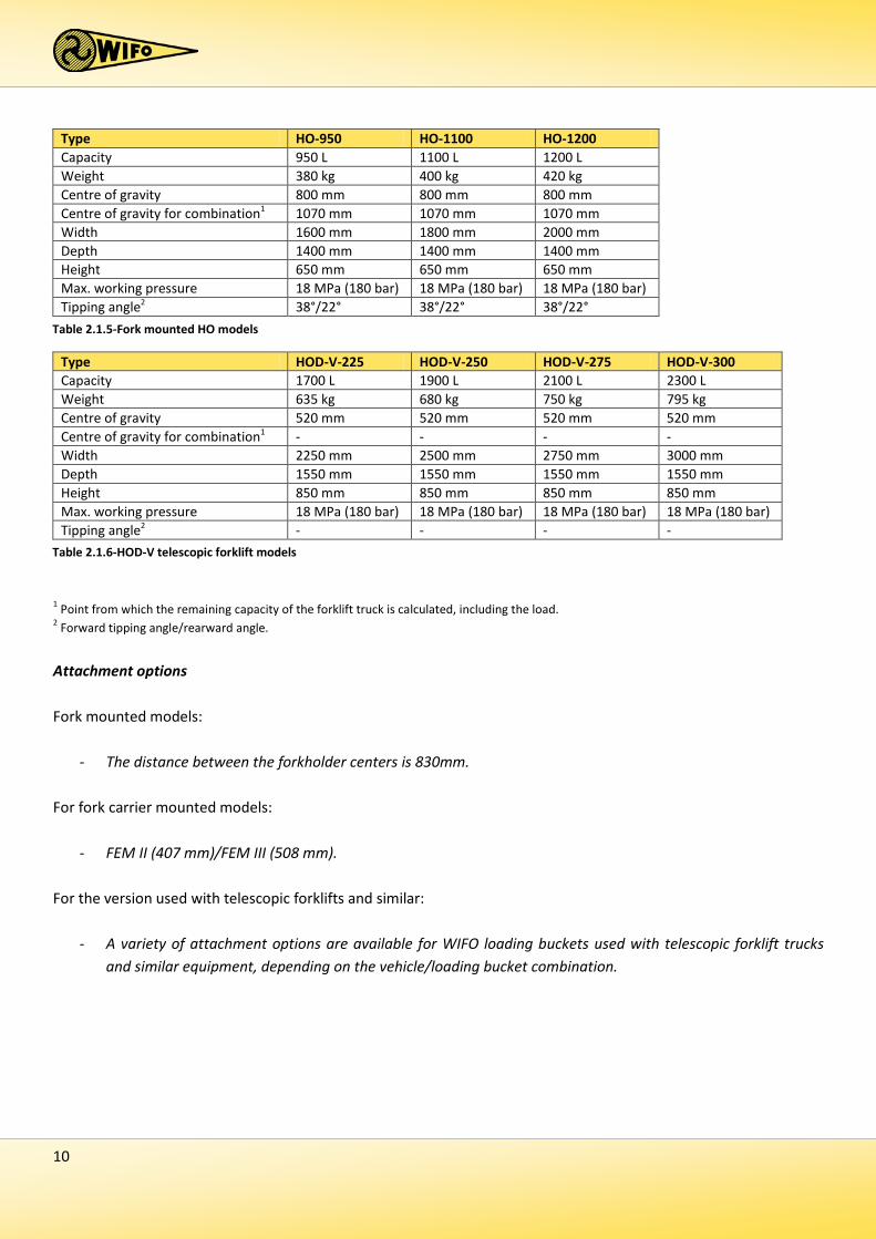
1 Point from which the remaining capacity of the forklift truck is calculated, including the load. 2 Forward tipping angle/rearward angle.
Attachment options Fork mounted models:
- The distance between the forkholder centers is 830mm. For fork carrier mounted models:
- FEM II (407 mm)/FEM III (508 mm). For the version used with telescopic forklifts and similar:
- A variety of attachment options are available for WIFO loading buckets used with telescopic forklift trucks and similar equipment, depending on the vehicle/loading bucket combination.
Type HO-950 HO-1100 HO-1200 Capacity 950 L 1100 L 1200 L Weight 380 kg 400 kg 420 kg Centre of gravity 800 mm 800 mm 800 mm Centre of gravity for combination1 1070 mm 1070 mm 1070 mm Width 1600 mm 1800 mm 2000 mm Depth 1400 mm 1400 mm 1400 mm Height 650 mm 650 mm 650 mm Max. working pressure 18 MPa (180 bar) 18 MPa (180 bar) 18 MPa (180 bar) Tipping angle2 38°/22° 38°/22° 38°/22°
Table 2.1.5-Fork mounted HO models
Type HOD-V-225 HOD-V-250 HOD-V-275 HOD-V-300 Capacity 1700 L 1900 L 2100 L 2300 L Weight 635 kg 680 kg 750 kg 795 kg Centre of gravity 520 mm 520 mm 520 mm 520 mm Centre of gravity for combination1 - - - - Width 2250 mm 2500 mm 2750 mm 3000 mm Depth 1550 mm 1550 mm 1550 mm 1550 mm Height 850 mm 850 mm 850 mm 850 mm Max. working pressure 18 MPa (180 bar) 18 MPa (180 bar) 18 MPa (180 bar) 18 MPa (180 bar) Tipping angle2 - - - -
Table 2.1.6-HOD-V telescopic forklift models

11
2.2 Fork mounted HOD
2.2.1 Parts list
Number Description 1 Frame 2 Bucket 3 Cylinder plate 4 Blade 5 Hose clip 6 Cylinder plate bearing 7 Cylinder DW 63-35-1000 8 Bolt with self-locking nut 9 Strip hinge 10 Washer 11 Strip hinge pin 12 Securing hook 13 Bolt with locknut 14 Securing hook pin 15 Wearing strip
Table 2.2.1-Parts list for fork mounted HOD models

12
2.3 Fork carriage mounted HOD-F
2.3.1 Parts list
Number Description 1 Frame 2 Bucket 3 Bronze frame bushing 4 Cylinder plate 5 Blade 6 Hose clip 7 Cylinder plate bearing 8 Cylinder DW 70-35-600 9 Cylinder pin 10 Bucket pin 11 Washer 12 Wearing strip
Table 2.3.1-Parts list for fork carriage mounted HOD-F

13
2.4 Fork mounted HOD-Z
2.4.1 Parts list
Number Description 1 Frame 2 Bronze frame bushing 3 Bucket 4 Bronze bucket bushing 5 Cylinder plate 6 Blade 7 Cylinder plate bearing 8 Hose clip 9 Cylinder DW 63-35-1000 10 Bolt with self-locking nut 11 Strip hinge 12 Washer 13 Hinge pin 14 Securing hook 15 Bolt with locknut 16 Securing hook pin 17 Wearing strip
Table 2.4.1-Parts list for fork mounted HOD-Z
14
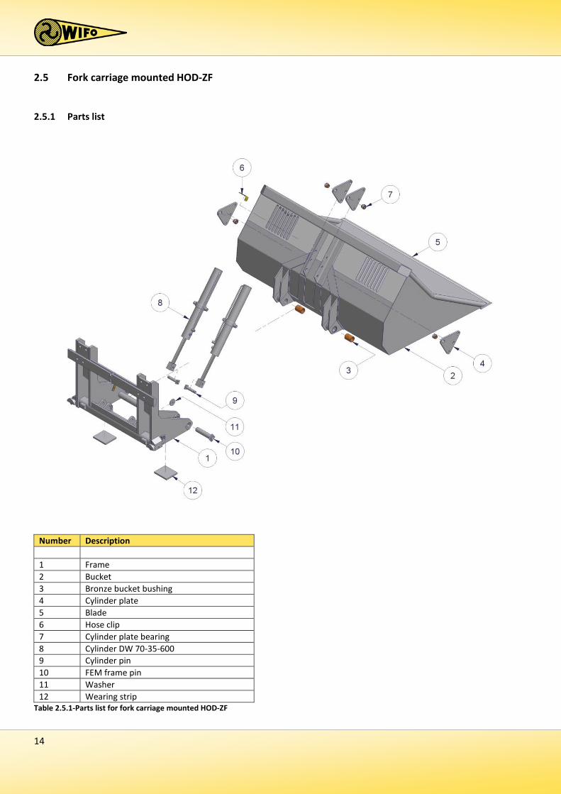
2.5 Fork carriage mounted HOD-ZF
2.5.1 Parts list
Number Description 1 Frame 2 Bucket 3 Bronze bucket bushing 4 Cylinder plate 5 Blade 6 Hose clip 7 Cylinder plate bearing 8 Cylinder DW 70-35-600 9 Cylinder pin 10 FEM frame pin 11 Washer 12 Wearing strip
Table 2.5.1-Parts list for fork carriage mounted HOD-ZF

15
2.6 Fork mounted HO
2.6.1 Parts list
Number Description 1 Frame 2 Bucket 3 Cylinder plate 4 Blade 5 Hose clip 6 Cylinder plate bearing 7 Cylinder DW 63-35-750 8 Bolt with self-locking nut 9 Strip hinge 10 Washer 11 Hinge pin 12 Securing hook 13 Bolt with locknut 14 Securing hook pin 15 Wearing strip
Table 2.6.1-Parts list for fork mounted HO

16
2.7 HOD-V for telescopic forklift trucks, front loaders, mobile shovels
2.7.1 Parts list
Number Description 1 Bucket 2 Blade 3 Wearing strip
Table 2.7.1-Parts list HOD-V
17
2.7.2 Commissioning fork mounted hydraulic bucket 1. Place the forklift truck or lifting mast forks the correct distance apart (830 mm centres) so that the hydraulic
bucket is located centrally in front of the vehicle. 2. Drive the vehicle forward and engage the forks as deeply as possible into the bucket's fork holders. 3. Use the securing hook or chain to fix the bucket frame to the forklift truck or lifting mast fork carrier, so that
the bucket cannot slip from the forks. 4. With the bucket slightly raised, the bolts must be tightened that they just clear the forklift truck or lifting
mast forks. Secure these bolts using the locknuts supplied. 5. Connect the hydraulic hoses and ensure that the quick connectors are clean so that no contamination is
introduced to the machine's hydraulic system. 6. Next, check that all hydraulic hoses are free to move throughout their length, and inspect for oil leaks. 7. Check the operation of the loading bucket using the hydraulic controls.
2.7.3 Commissioning fork carrier mounted hydraulic bucket
1. Remove the forks from the forklift truck or forklift mast. 2. Make sure the fork carrier is straight and clean. 3. Locate the loading bucket on the forklift truck or lifting mast fork carrier. 4. Make sure the locking cam slots into the recess in the centre of the fork carrier. If no recess is available:
a) Grind such a recess; or b) Grind off the locking cam from the loading bucket and fit a suitable locking cam in an existing recess in the
fork carrier, so that the loading bucket is positioned in the centre of the fork carrier and cannot slide sideways.
5. Lock the bucket to the fork carrier by giving the locking handles a half turn so that the profiled half discs engage at the rear of the fork carrier. Use the locking spring to secure the handles.
6. Connect the hydraulic hoses and ensure that the quick connectors are clean so that no contamination is introduced to the machine's hydraulic system.
7. Next, check that all hydraulic hoses are free to move throughout their length, and inspect for oil leaks. 8. Check the operation of the loading bucket using the hydraulic controls.
18
2.7.4 Commissioning of bucket connected to telescopic forklift, front loader or mobile shovel
1. Remove the pins from the quick attachment frame. 2. Tip the quick attachment frame forwards using the tipping cylinders and hook the loading bucket onto the
telescopic forklift, front loader or mobile shovel. The hooks must engage between the quick attachment system guide strips.
3. Now tip the quick attachment frame to the rear using the tipping cylinders, and replace the pins with their securing pins, so that the loading bucket is firmly attached.
4. Connect the hydraulic hoses and ensure that the quick connectors are clean so that no contamination is introduced to the machine's hydraulic system.
5. Next, check that all hydraulic hoses are free to move throughout their length, and inspect for oil leaks. 6. Check the operation of the loading bucket using the hydraulic controls.
The WIFO bucket is now ready for use.
19
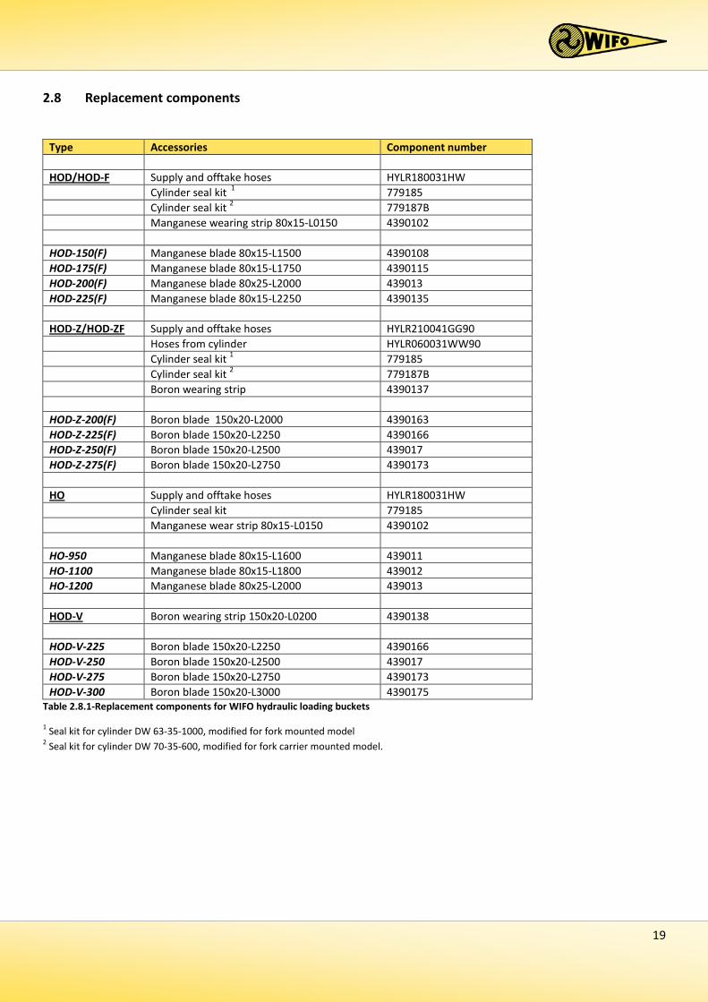
2.8 Replacement components
Type Accessories Component number
Supply and offtake hoses HOD/HOD-F HYLR180031HW Cylinder seal kit 1 779185 Cylinder seal kit 2 779187B Manganese wearing strip 80x15-L0150 4390102 HOD-150(F) Manganese blade 80x15-L1500 4390108 HOD-175(F) Manganese blade 80x15-L1750 4390115 HOD-200(F) Manganese blade 80x25-L2000 439013 HOD-225(F) Manganese blade 80x15-L2250 4390135
Supply and offtake hoses HOD-Z/HOD-ZF HYLR210041GG90 Hoses from cylinder HYLR060031WW90 Cylinder seal kit 1 779185 Cylinder seal kit 2 779187B Boron wearing strip 4390137 HOD-Z-200(F) Boron blade 150x20-L2000 4390163 HOD-Z-225(F) Boron blade 150x20-L2250 4390166 HOD-Z-250(F) Boron blade 150x20-L2500 439017 HOD-Z-275(F) Boron blade 150x20-L2750 4390173
Supply and offtake hoses HO HYLR180031HW Cylinder seal kit 779185 Manganese wear strip 80x15-L0150 4390102 HO-950 Manganese blade 80x15-L1600 439011 HO-1100 Manganese blade 80x15-L1800 439012 HO-1200 Manganese blade 80x25-L2000 439013
Boron wearing strip 150x20-L0200 HOD-V 4390138 HOD-V-225 Boron blade 150x20-L2250 4390166 HOD-V-250 Boron blade 150x20-L2500 439017 HOD-V-275 Boron blade 150x20-L2750 4390173 HOD-V-300 Boron blade 150x20-L3000 4390175
Table 2.8.1-Replacement components for WIFO hydraulic loading buckets
1 Seal kit for cylinder DW 63-35-1000, modified for fork mounted model 2 Seal kit for cylinder DW 70-35-600, modified for fork carrier mounted model.

20
3. Maintenance and troubleshooting
Ensure that the loading bucket is in its lowest position and flat on the ground. Prevent the unintended tipping and/or raising of the bucket during maintenance activities by switching off the vehicle's engine and removing the ignition key. An additional precaution would be to disconnect the hydraulic hoses.
3.1 Preventive maintenance and lubrication
After the first 8 working hours:
- Check the connections and turnbuckles of the hydraulic hoses. - Tighten all bolts to 105 Nm.
N.B.: Please read the instruction manual prior to any maintenance to the machine! Turn off the engine and remove the key from the ignition while maintenance is carried out on the machine!
Regularly check the hydraulic system for any leaks. Never try and search for leaks or stop a leak by hand. Liquid under high pressure can easily penetrate skin and clothing, and may cause serious injuries. Replace any damaged hydraulic hoses to prevent bursting and subsequent injury.
Regularly check the oil level of the hydraulic system of your tractor/forklift.
This sticker shows the position of a grease nipple on the machine. Lubricate the machine after every 10 working hours. Recommended lubricants include SAE 30 oil and Grade 2 lithium-based grease.
The fork mounted loading buckets type HOD-, HOD-Z and HO are equipped with a grease nipple in each pin of the hinges. It’s strongly recommended to lubricate these hinges after every 10 working hours.
21
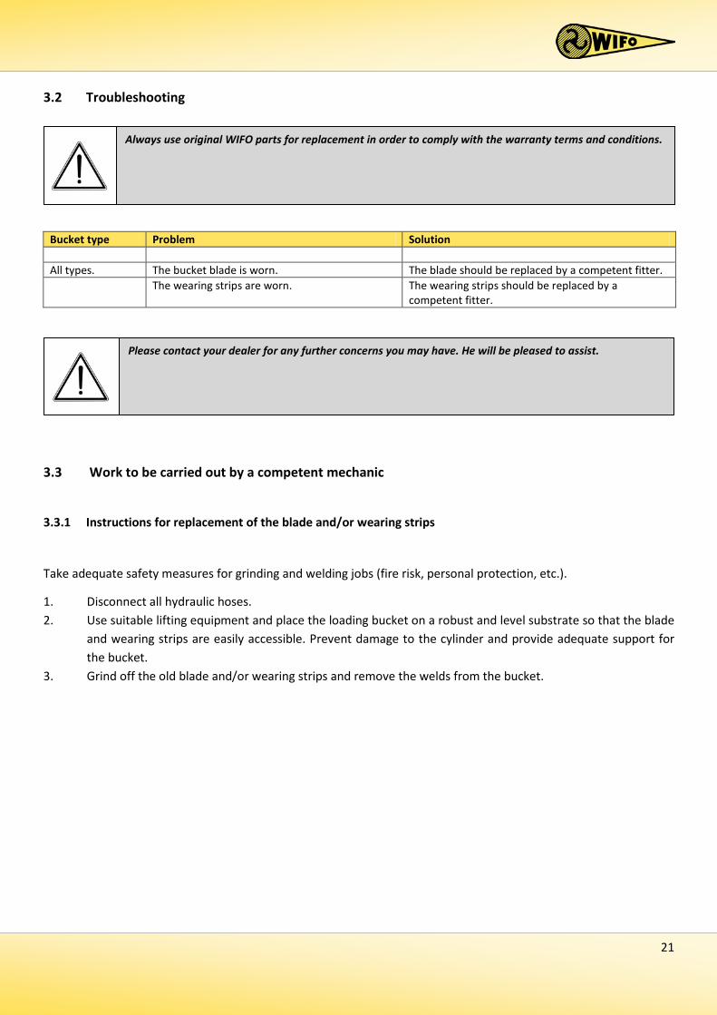
3.2 Troubleshooting
Bucket type Problem Solution All types. The bucket blade is worn. The blade should be replaced by a competent fitter. The wearing strips are worn. The wearing strips should be replaced by a
competent fitter.
3.3 Work to be carried out by a competent mechanic
3.3.1 Instructions for replacement of the blade and/or wearing strips
Take adequate safety measures for grinding and welding jobs (fire risk, personal protection, etc.).
1. Disconnect all hydraulic hoses. 2. Use suitable lifting equipment and place the loading bucket on a robust and level substrate so that the blade
and wearing strips are easily accessible. Prevent damage to the cylinder and provide adequate support for the bucket.
3. Grind off the old blade and/or wearing strips and remove the welds from the bucket.
Please contact your dealer for any further concerns you may have. He will be pleased to assist.
Always use original WIFO parts for replacement in order to comply with the warranty terms and conditions.
22
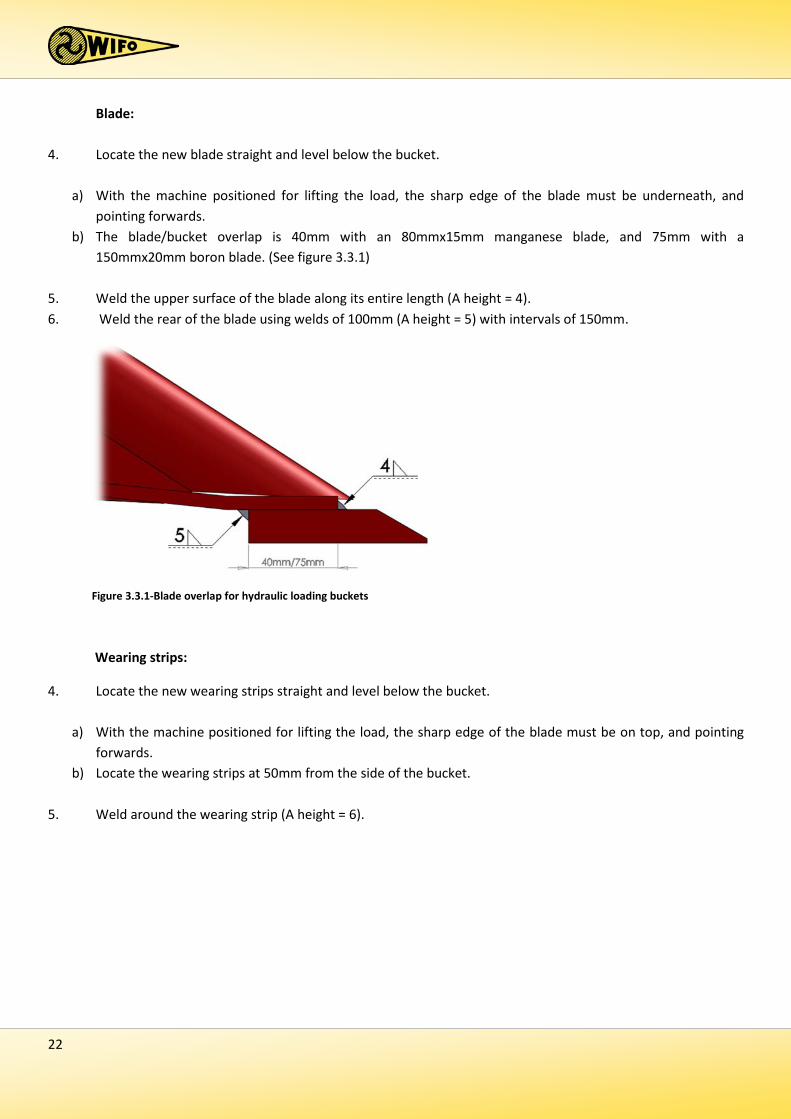
Blade:
4. Locate the new blade straight and level below the bucket.
a) With the machine positioned for lifting the load, the sharp edge of the blade must be underneath, and pointing forwards.
b) The blade/bucket overlap is 40mm with an 80mmx15mm manganese blade, and 75mm with a 150mmx20mm boron blade. (See figure 3.3.1)
5. Weld the upper surface of the blade along its entire length (A height = 4). 6. Weld the rear of the blade using welds of 100mm (A height = 5) with intervals of 150mm.
Wearing strips:
4. Locate the new wearing strips straight and level below the bucket.
a) With the machine positioned for lifting the load, the sharp edge of the blade must be on top, and pointing forwards.
b) Locate the wearing strips at 50mm from the side of the bucket.
5. Weld around the wearing strip (A height = 6).
Figure 3.3.1-Blade overlap for hydraulic loading buckets


EG-VERKLARING VAN OVEREENSTEMMING VOOR MACHINES EC-DECLARATION OF CONFORMITY FOR MACHINERY EG-MASCHINENÜBEREINSTIMMUNGSERKLÄRUNG DÉCLARATION DE CONFORMITÉ “CE” POUR MACHINES
Fabrikant/Manufacturer/Fabrikant/Fabricant:
WIFO-Anema B.V.
Adres/Address/Adresse/Adresse:
Hegebeintumerdyk 37 9172 GP Ferwert The Netherlands Verklaart hiermede dat /Herwith declares that/Erklärt hiermit, daβ/Déclare ci-après que Serienummer/Serial number/Serienummer/Numéro de série: Uitvoering/Model/Ausführung/Modèle:
- Voldoet aan de bepalingen van de Machinerichtlijn (Richtlijn 2006/42/EG, zoals laatstelijk gewijzigd) en de nationale wetgeving ter uitvoering van deze richtlijn;
- Is in conformity with the provisions of the Machine Directive (Directive 2006/43/EC, as amended) and with national implementing legislation;
- Konform ist min den einschlägigen Bestimmungen der EG-Maschinerichtlinie (EG-Richtlinie 2006/42/EG), inclusive deren Änderunge, sowie mit dem entsprechenden Rechtserlaβ zur Umsetzung der Richtlinie in nationales Recht;
- Est conforme aux dispositions de la Directive “Machines” (Directive 2006/42/EC telle que dernièrement modifiée) et la législation nationale adoptée en application de ladite directive.
Ferwert, March 2009 Wytze Anema (Director)