Embed Size (px)
Citation preview

PRESENTATIONON
MAT FOUNDATION
Department of Civil Engineering
1

Md. Abdul Ahad12-01-03-104
Presented By
Monisha Podder12-01-03-110
Arafat Chowdhury12-01-03-116
Sabrina Zissan12-01-03-124
Mahbub Al Muhaimin12-01-03-129
Abu bakar Siddik12-01-03-136
Sabrina Mehenaz12-01-03-144
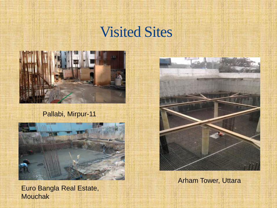
Visited Sites
Arham Tower, Uttara
Pallabi, Mirpur-11
Euro Bangla Real Estate,
Mouchak
MAT Foundation• Primary shallow foundation;
• Also known as Raft;
• Large footing extended over the whole construction area;
• Supports many columns;
• Foundation for high rise buildings with basement;
• Depth 1~20 feet.

PCC BED
R C C SLAB
C C
Sectional View
Plan View
COLUMN
MAIN BEAM
SECONDARY
BEAM
MAIN BEAM

When we construct MaT foundation?
• When the area of individual column footings cover
more then 50% area of total land;
• When the bearing capacity of soil is too weak to
support a structure;
• When the cost of deep foundation is higher then
Raft foundation.
• When the structural load is too high.

Types of MAT
Flat Plate MatTwo-way Beam & SlabFlat Plate Thickened Under
Column
Flat Plate with Pedestals Pile Mat Rigid Frame mat
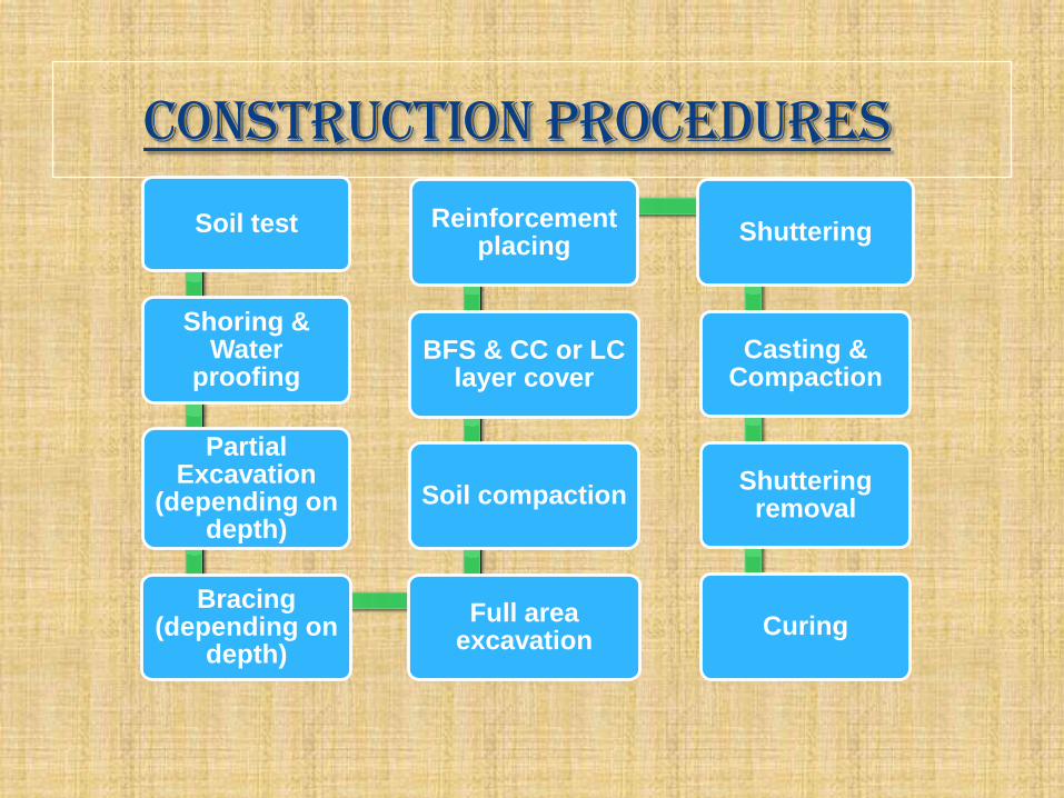
construction Procedures
Soil test
Shoring & Water
proofing
Partial Excavation
(depending on depth)
Bracing (depending on
depth)
Full area excavation
Soil compaction
BFS & CC or LC layer cover
Reinforcement placing
Shuttering
Casting & Compaction
Shuttering removal
Curing
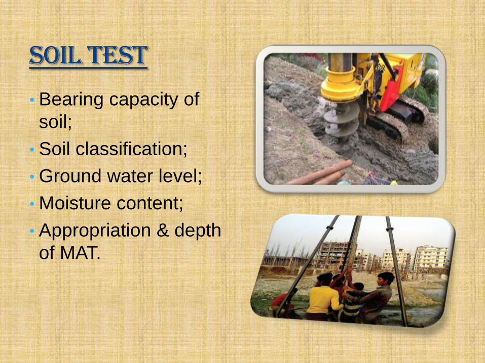
Soil Test
• Bearing capacity of
soil;
• Soil classification;
• Ground water level;
• Moisture content;
• Appropriation & depth
of MAT.

Shoring• Shoring is commonly used when installing the
foundation;
• Shoring support the surrounding loads until the
underground levels of the building are
constructed.
• Can be of 3 types: Pile shore, steel sheet shore
and timber shore.

Log Shore Pile Shore
Steel Shoring

Water proofing
• A layer provided over
shoring to prevent
moisture;
• Cement mortar or steel
sheet layer over
shoring;
• Cement mortar layer is
extended over wire
mesh.

Bracing
• A horizontal support for
the boundary shores
during excavation and
foundation;
• Depends on the depth of
foundation;
• Also known as horizontal
shores.

Other factors
Shotcrete leveling
layer with steel mesh
Retaining Wall
King Post

BFS and CC
Layer of bricks
on the earth
Layer of cement
concrete over BFS.

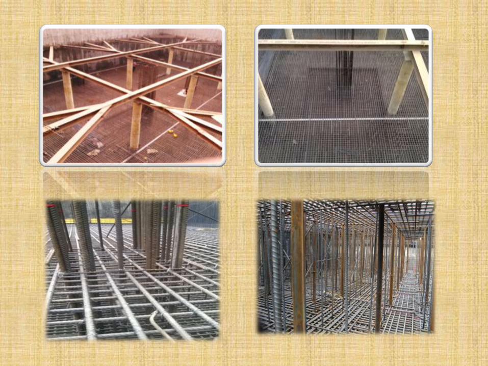
Reinforcement placing
• A batch of horizontal reinforcement placing;
• Another batch of reinforcement placement to complete the bottom mesh;
• Column rod placement;
• Vertical rod (chair) placement over bottom mesh to hold the upper mesh;
• Upper mesh placement.


Important factors
Reinforcement Selection
• 60~72.5 Graded
• 12mm~25mm
Reinforcement Joint
• Heavy Steel wire binding
Chair
• Distance
• Bending

Important factors
Hook
• Right angled
Rod Cutter
Rod bender

Shuttering
• Steel plate shutter;
• Timber shutter.

Cast Material
• Mixture ratio 1:2:4;
• Sylhet sand is used
over 50%;
• Stone chips that are
used normally is
½”~¾” in size;
• Stone chips are
preferred than brick
chips.

Casting
• Start from one end;
• Layer basis casting;
• Side basis casting.
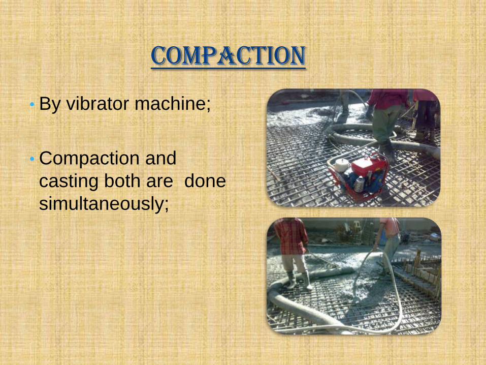
Compaction
• By vibrator machine;
• Compaction and
casting both are done
simultaneously;

Precautions for casting
• Materials like piece of wood, polythene etc. must be
removed before casting from that area;
• Shuttering must be leak proof;
• Cast pouring height is less than 5 feet ;
• Pouring and compaction both are done simultaneously.

Curing