Embed Size (px)
Citation preview
l
\
PREFERENTIAL SPUTTERING,
.s1.
ill\
. ~.
\. ' ,.+-
\.
f'~ ....(~ >.~
,if.'
PREFERENTIAL SPUTTERING EFFECTS
IN Nb~05."
..
By.
OASARAO I{RISHNA MURTI, M. Se.
...
A *1'heiUs
Submitted to the SO~~:~ of Grad~ate~u~ies" ,
in Partial Fulfilment of tn~ Requirem~ts
.for the Degree
Dopto~ of'Phi~osophy
..
•
DOCTOR OF PHILOSOPHY (1975)(Materials Science)
McMASTER UNIVERSItyHamilton, Ontario
I I,
TITLE: Preferential Sputtering Effects in Nb20S
f
\
•
il
• I

'.
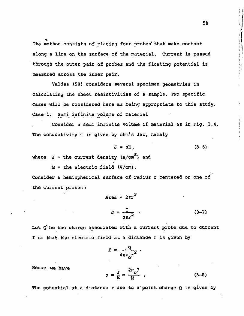
Ion bombardment has been used as a technique for the sput-
tering of metals for several- years1 very few studies have, how
ever, been made on alloys and ~ompounds, especially studies where
~he target itself was analyzed after 'ion bombardment. In this
" ABSTRACT
...
.thesis results are presented concerning the c~n~es in targets
of Nb20 S and related systems due to -ion bombardment. The targets
used were in the form of'anodic thin films and sintered pellets.. + +Bombardments were carried out using Kr and. 02 ions with energies
of 2 to 3S keV and at 4o~es v~rying from 1013 'to 1017 ions/cm2•
The structural changes induced by the bombardment were studied .
o with an electron microscope and the cha~ges in electrical conduc-
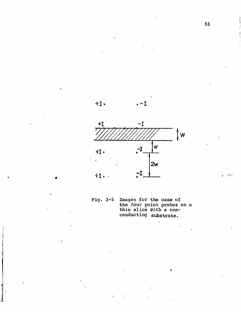
tivity were stuftied with a four point probe.
The results indicate that an altered 'layer is formed which.
has the stoichiometry ~f NbO when Nb20Starg~ts are bombarded
'with 35 ke; ions ~t_ high doses (~ 1 x 10¹⁷ ions/cm2>. A technique
based on the changes in the chemical reactivity of the altered~ .
lay~r as compar~d to the substrate is used to estimate' the thickness. ,
of the a~tered lay~r. That on Nb20S varies.from 18 nm at very
low doses (SX1013 io~s/cm2) t9 23 nm at high doses (lxl017 ions/cm2).
The con4uctivity of the altered ~a~er formed at high doses is about
4xio~ slm, ~n i~o~ease QY a 'factor-of iX108, An energy threshold, "
for oonductivity changes was found using an oxygen :Lon beam,.. ., ~ r ...
whereas 10: ion bombardment reveals conductivity changes at all,y ... .
Oxygen loss from bombarded Nb20S can be considered to• f
have threQ alternative origins based on a vaporiaation model, an~ ~
internal displacement model and a preferential sputtering model.,
The results favour the preferential sputtering of oxygen as the
likely mechanism to explain the altered layer in the ta~get. A
modified'sputtering mode~ explains the energy thr~Bhold effect
f'fI.'
observed when a~ oxygen beam is used. \
Several applications of the techniques and results pre-
sented here have been considered. Th~y include, among ~thers,
. _ t-~ating of minerals, limitations of surface analytical techniques,
and preliminary results for Ta~OS'
j
(
•
ACI<NOt1LEDG~1ENTS
I am indebted to Dr. R. Kelly for his continuous
gUidance, encouragement and friendship throughout the course
of this work. I wish to express my sincere gratitude to the
members of my supervisery committee, Drs. J. D. Embury,
C.J.L. tock and Professor C. M. Sargent for their interest
and encouragement.
Thanks are due to Dr •• P. Sig,mund (U~iversity of
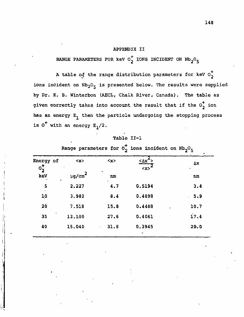
Copenhagen) for supplying Fig. 2-3 and Dr. 'K. B. Winterbon (AECL!.Chalk River) for supplying the data on range Prrameters in
Nb20S (Table II-I). The technical a~sistance of F. Smith and.D. Hodgson is greatly appreoiated. I wish to thank Mrs~ H.
Rennelly for her skill and patience in typing this thesis.
This work was supported by grants from 'the Defence
Research Board ~f Canada, the National Research Council of
Can.ada, and the Geological Survey of Canada- .to Dr. R. Kelly.
I thank the National ~esearch Council of Canada for the award
of ~ P.I.E.R. fellowship and McMaster University for the
award.of a teaching assistantship.
Finally; I am deeply grateful to my.wife, Brinda, for\
her patience and constant suppor~ throughout the course of
'-this work.
TABLE OF CONTENTS
CHAPTER 1 INTRODUCTION 1
1.1 PARTICLE SOLID INT~RACTIONS 1
1.2 APPLICATIONS OF SPUTTERING 4"
1.3 MODIFICATIONS OF THE SPUTTERED SURFACE 8
1.4 WHY STUDY Nb20S? 12....
CHAPTER 2 A REVIEW OF iON IMPACT THEORY 15
2.1 INTRODUCTION 15
2.2 ENERGY LOSS MECHANISMS 18
2.3 LSS THEORY.
2..4 APPLICATION OF LSS THEORY
2.5 WSS THEORYCo
2.6 RANGE AND D~GE PROFILES
20
24
26
29
2. 7~' fl'HEQRY OF ROt, FLU IT AND KISTEMAKER 30
2.8 SIGMUND'S THEORY OF SPUTTERING 31
2.9 ENERGY DISSIPATION, IN COMPOUND TARGETS 36
CHAPTER 3 SXPERlMENTAL TECHNIQUES . 41•
\
.3.1 '. SAMPLE PREP-MAT.ION
3.1.1 Anodic Thin Films of Nb20S', .
3.1.2 Sintered Pellets
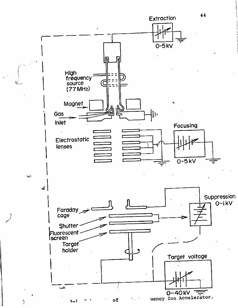
3.2 ION, BOMBARD~T
(3.3 ELECTRICAL CONDUCTIVITY MEASUREl<1ENTS .
41
41
42
43
46-
46
47
"
3.4 ELECTRON MICROSCOPY
3.4.1 Introduction
3.4.2 Transmission Mode
3.4.3 Reflection Mode
Page
57
'57
58
·61
3.4.4 ~nalysis of Electron Diffraction Patterns 63
CHAPTER 4 EXPERIMENTAL RESULTS: STRUCTURAL CHANGES 67
4.1 INTRODUCTION 67
4.2 STRUCTURE OF AMORPHOUS MATERIALS 68
4.3 THIN FILMS OF Nb20S 70
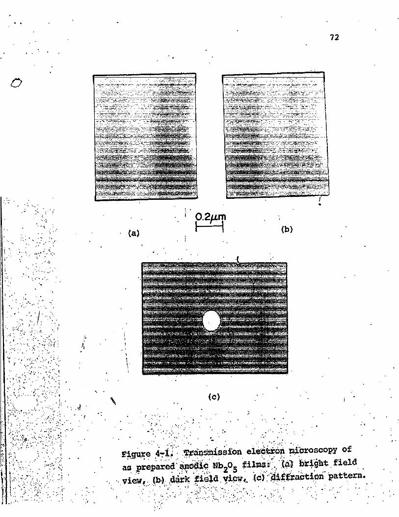
4.j.l Structure of as Prepared Films 70
4.3.2 Effect of Ion Dose
4.4
4.5
CHAPTER 5
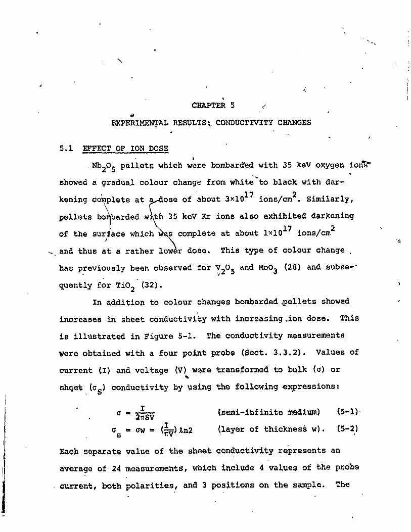
5.1
5.2
-5.3
5.4
5.5
CHAPTER 6
6.1
6.2
SINTERED Nb20S PELLETS
SUMMARY
EXPER!MENTAL RESULTS: CONDUCTIVITY'CHANGES
EFFECT OF' ION DOSEI
EFFECT OF ION ENERGY
ANNEALING OF CONDUCTIVITY
EFFECT OF ION CURRENT
SUMMARY AND CONCLUSIONS
gxpERIMEN'I'AL RESULTS: 'l'HICKNESS OFAL'l'EREO LAYER
INTRODUCTION
THICKNESS OF AL'l'E~ LAYER 1\'1' LOW TOMED;IUM DOSES
73
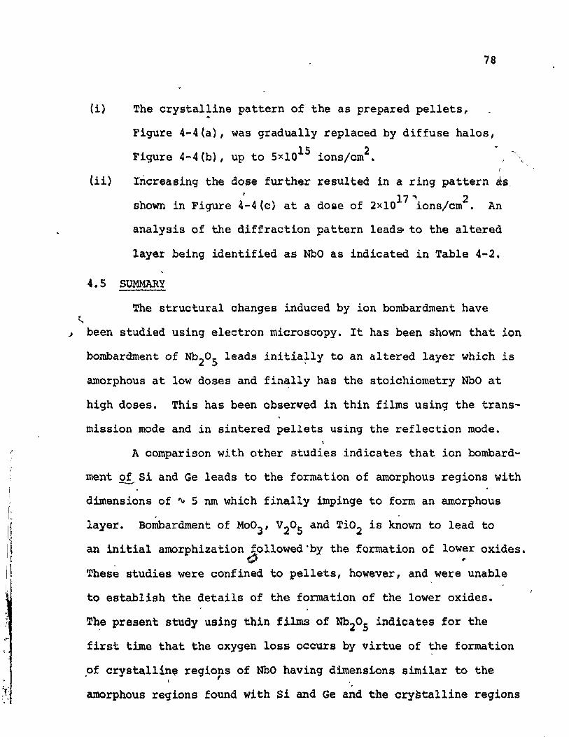
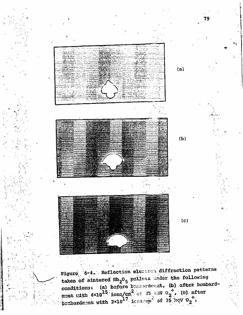
77
18
82
82
84
86
88
91
93

t-, \IIi I
I
Page.i
6.4 IMPLICATIONS OF THICKNESS OF NbO LAYER 10~
6.S SUMMARY AND CONCLUSIONS 103
CHAPTER 7 DISCUSSION OF EXPERIMENTAL RESULTS 104
7.1 INTRODUCTION 104
7.2 MECHANISMS FOR OXYGEN LOSS lOS
7.2.1 Vaporization Model 105,7.2.2 Internal Displacement Model 105
7.2.3 Preferential Sputtering Model 107
7.3 SPUTTERING MODEL APPLIED TO AN OXYGEN 110BEAM
7.4 PREFERENTIAL SPUTTERING COMBINED WITH 117DIFFUSION
-----..7.4.1 Diffusion Model 117
7.4.2 Thickness 'of Altered Layer 122
7.5 SUMMARY 122
CHAPTER 8 APPLICATIONS 124
8.1 CHANGES IN AND CONTROL OF CONDUCTIVITY 124
8.2 PREPARATIQN OF LOwER VALENCE OXIDES 124
8.3 REDUCTION OF OXIDES - MICROWAVE DISCHARGE 125
8.4 MINERALS ON THE MOON AND IN THE EARTH! S 126INTERIOR
. 8.5 DATING OF MINERALS 127r'r "
8.6 PREFE~NTIAL SPUTTEtdNG EFFECTS IN SUR- 131'. FACE ANALYSIS
. •It 8.7 PREFERENTIAL SPUTTERING OF CERMET FILMS 135
-"
.'
8.8 ION BOMBARDMENT EFFECTS WITH Ta20S
Page
135
8.8.2
8.8.3
8.8,.4
CHAPTER 9
APPENDIX I
APPENDIX II
REFERENCES
Introduction ..Experimental Results - Conductivity 136Changes
Experimental Results - Structural 136Changes
Conclusions 138
SUMMARY 141
RANGE PARAMETERS FOR 35 keV 8SKr IONS 144
INCIDENT ON NbC....
RANGE PARAMETERS FOR + IONS INCIDENT 148keV 02ON Nb20 S
r 149
•
/

Images for the case of the four point probeson a thin slice with a non conductingsubs'trate
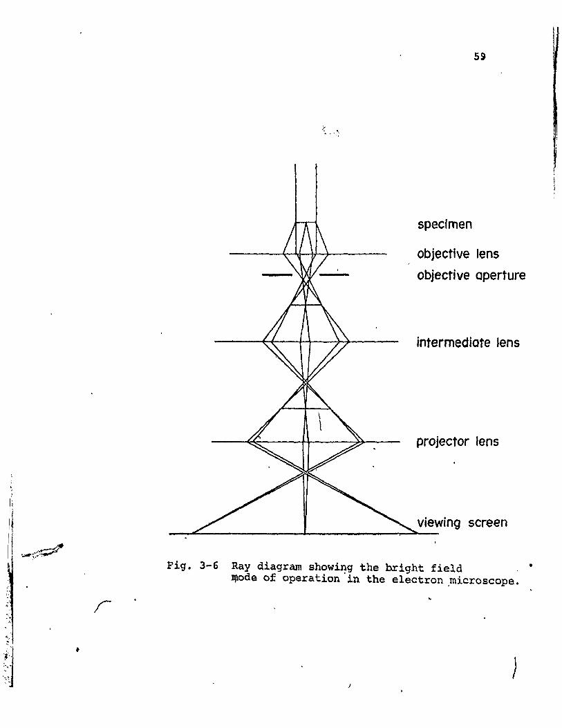
Ray diagram showing the bright field modeof operation
FIGURENO.
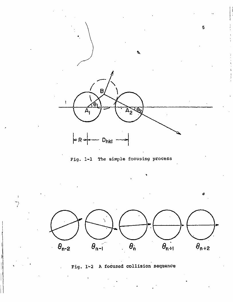
1-1
1-2
1-3 .
1";'4
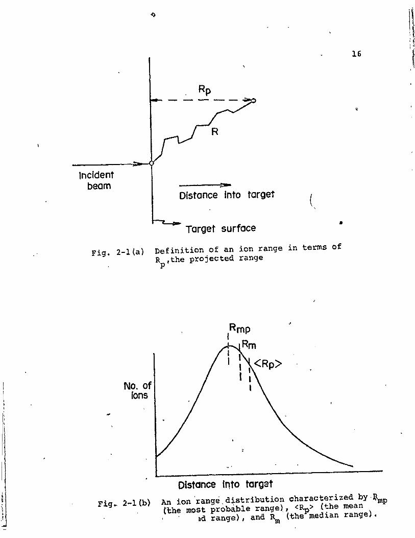
2-1 (a)
(b)
2-3
3-1
3-2
3-3
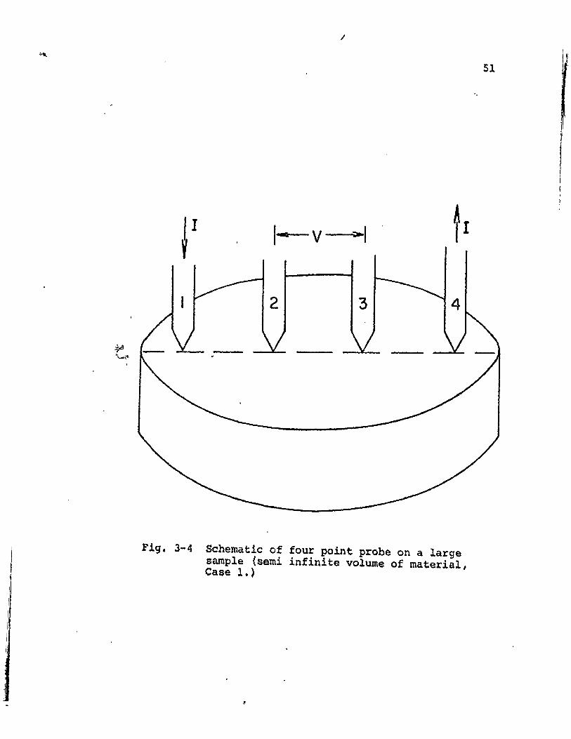
3-4
3-5
3-6
LIST OF ILLUSTRATIONS
TITLE
The simple focusing process
A focused collision sequence
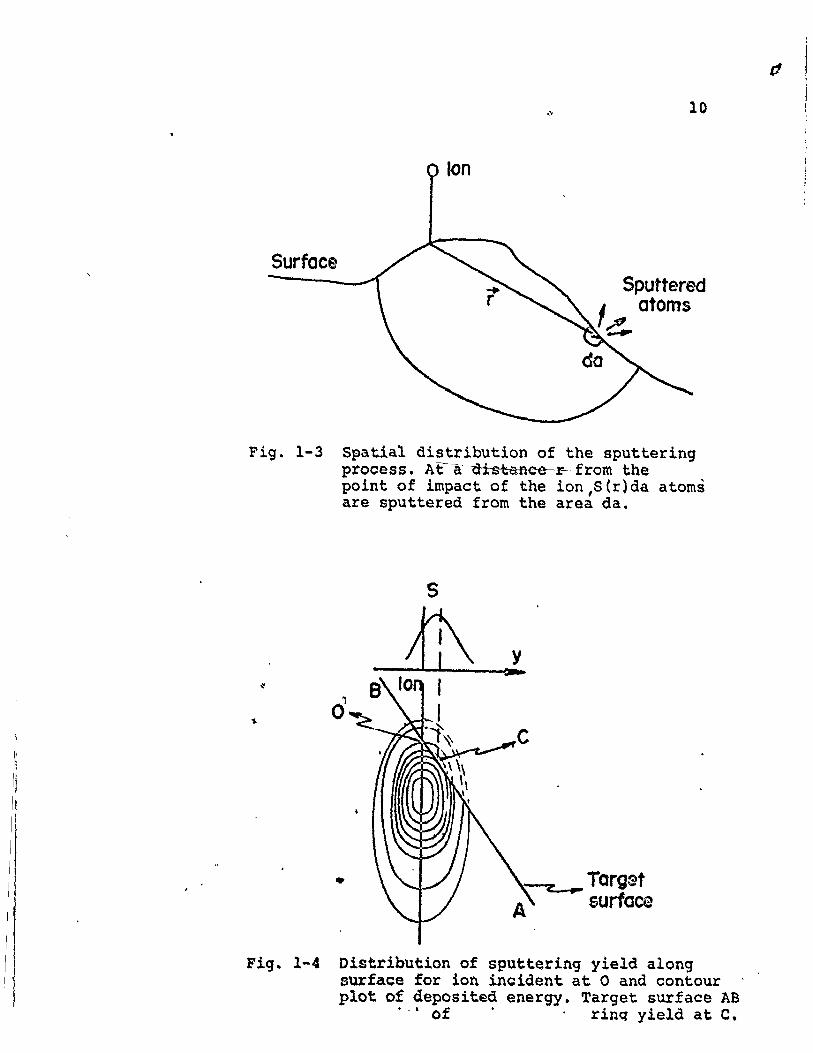
Spatial distributton of the sputteringprocess
Distribution of sputtering yield
Definition of ion range
Ion range distribution
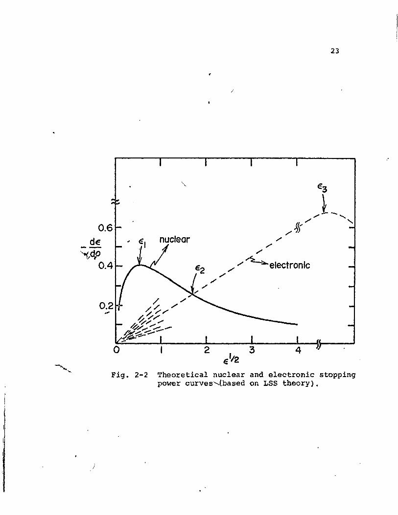
Theoretical nuclear and electronicstopping power curves
Displacement efficiencies for the systemNb-O
Radio frequency ion accelerator
Rectangularly shaped section of thin filmfor conductivity measurement
Schematic of conductivity measurementtechnique
Schematic of four point probe
PAGE
\ 5
5
10
10
16
.16
23
39
44
48
49
<,.. 51
S5
59
I1
3-7
4-1
4-2
, W'
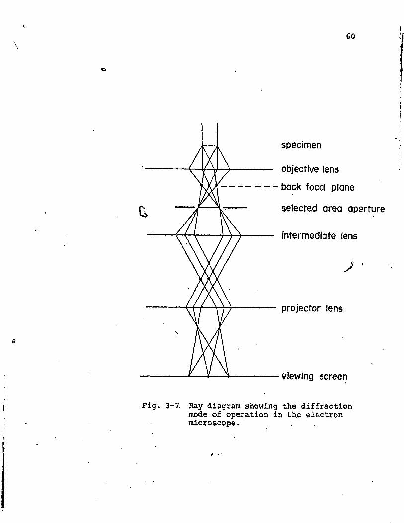
Ray diagram showing the diffraction 'mode, of operation
Transmission electron microscopy of asprepared anodic Nb2~S films
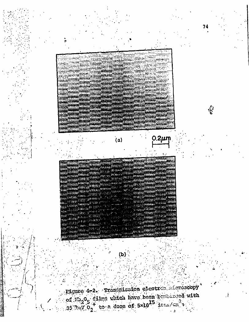
Transmission electron microscopy of Nb20~
films bombarded to a dose of.SX1015~ ion$/cm2
60
72

FIGURENO.
4-3
4-4
TITLE " PAGE '
Transmission electron microscopy of Nb20S·; ~ 75films bombarded to a dose of 5xl016 ions/cm2
Reflection electron diffraction patterns of 79sintered Nb20S pellets before 'and afterbombardment
sheet conduc-•
sheet conductivity
5-1
.f~5-2
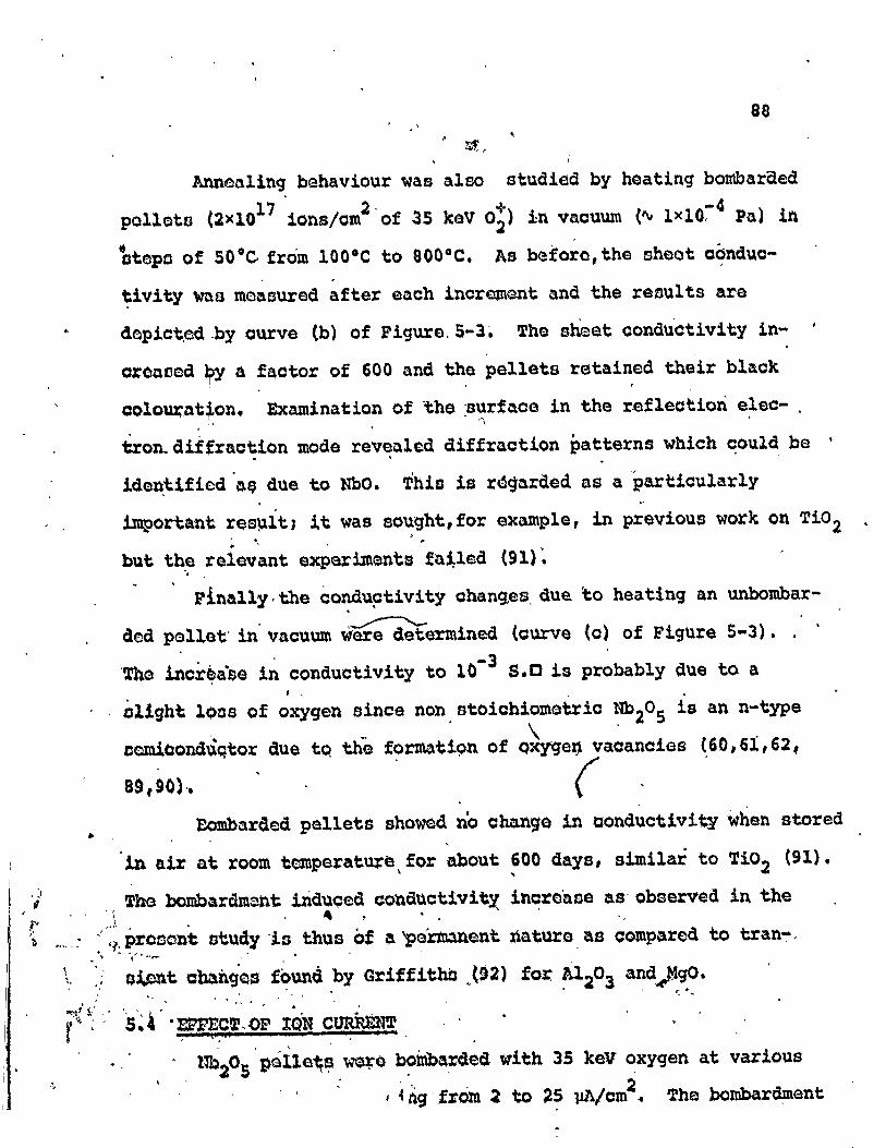
5-3
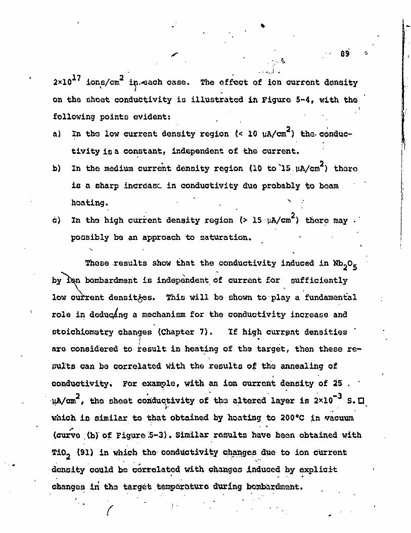
5-4
6-1
Effect of ion dose on the sheet conductivityof Nb20
Spellets
Effect of ion energy on the sheet conductivity of Nb20S pellets
Effect of annealings on theof bombarded Nb20S pellets
Effect of ion current on thetivity of Nb205 pellets
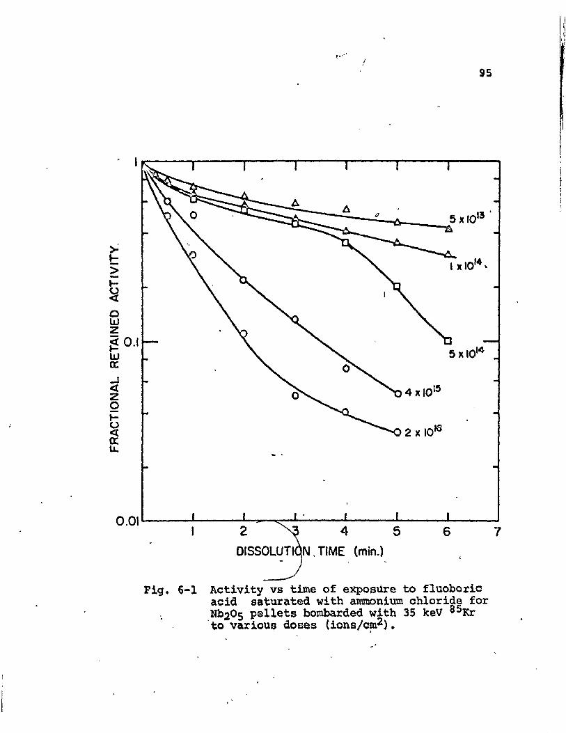
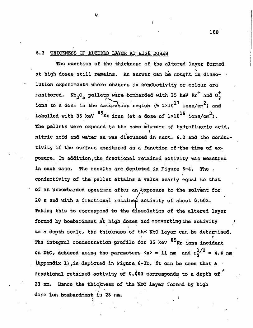
Activity versus time of exposure to fluoboricacid saturated with ammonium chloridg forNb2?5 pellets bombarded with 35 keV 5Kr tovar~Ous doses
83
90
95
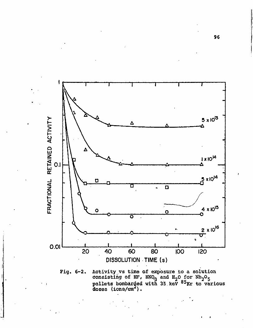
6-2 Activity versus time of exposure to a solution 96consisting of HF, NH03 and H20 for Nb205pellets bombarded with 35 keV 85Kr tovarious doses
6-3
6-4
7-1
7-2
7-3
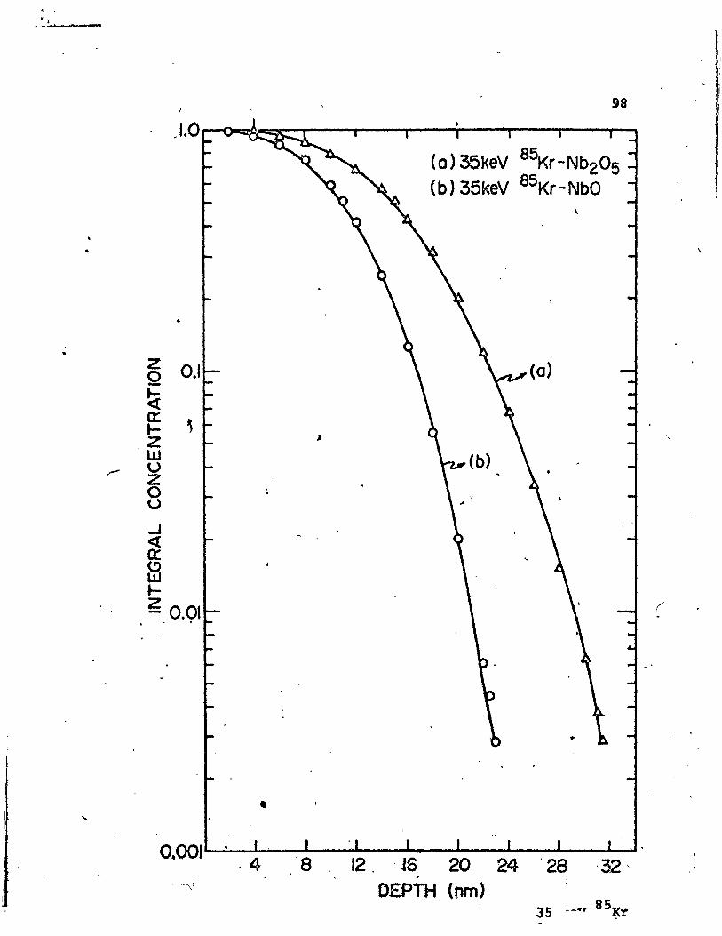
Igtegral concentration profiles for 35 keV8 Kr ions incident on a) Nb20S and b) NhO
Dissolution of altered layers formed onN~205 ~ellets bombarded with 35 keV Kr+ and02 :Lons ,
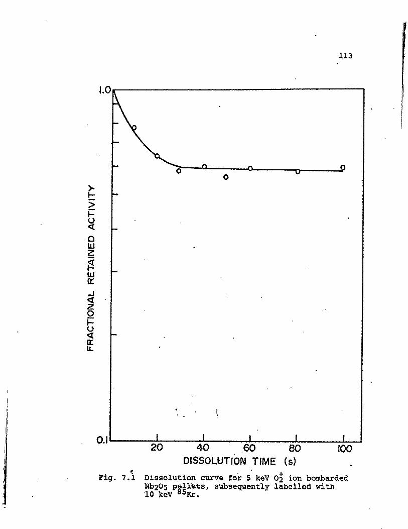
+Dissolution curve for 5 keV 02 ion bombardedI with Nb20S pellets
Integral concentration profile for 10 keV8SKr ions incidene on Nb20S
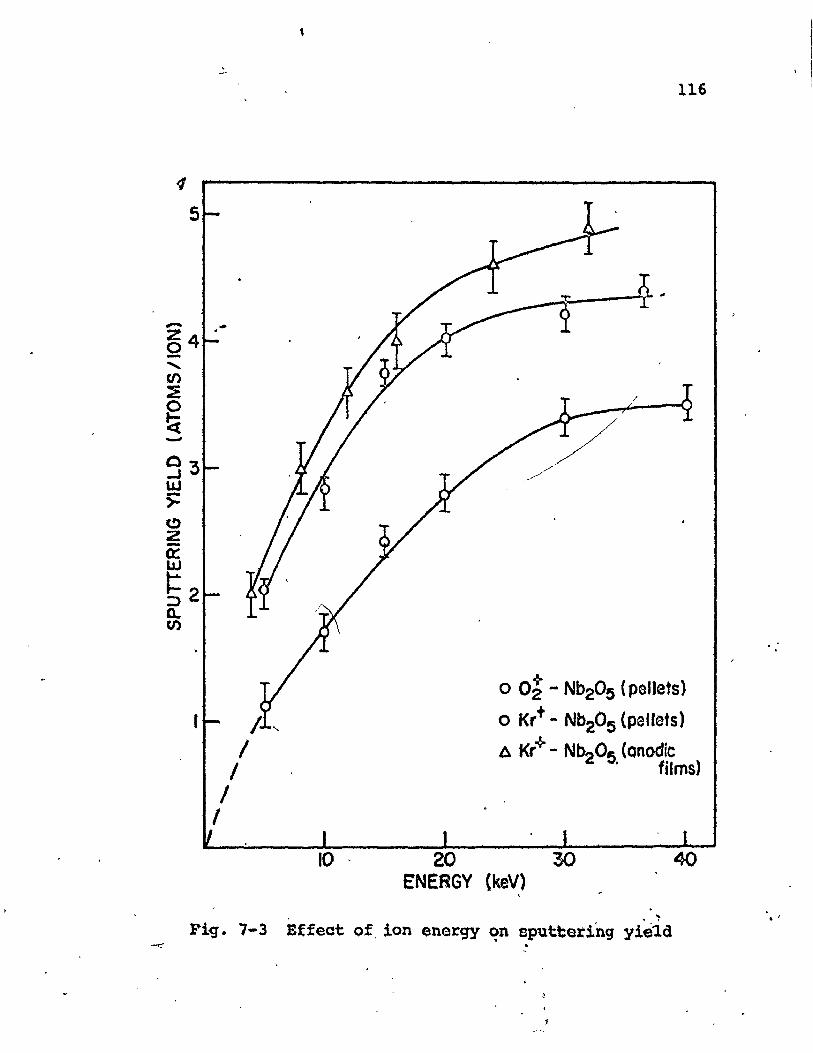
Effect of ion energy on ~puttering yield
•
98
101 '
113
114
116

,
FIGURENO.
8-1
8-2
8-3
8-4
8-S
8-6
TITLE
Reflection electro~ diffraction patternsfor columbite - before and after bombardment
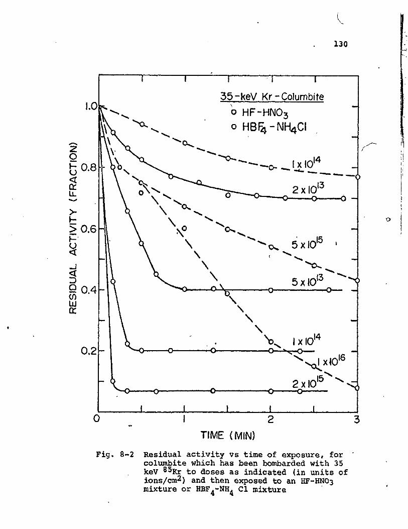
Dissolution ~urves for columbite bombardedwith 3S keV SKr ions to various doses
Q
X-ray photoelectron spectra of Mo03 exposedto Ar+ and O~ ions
Dependence of the photon yield from Al ~nthe oxygen pressure
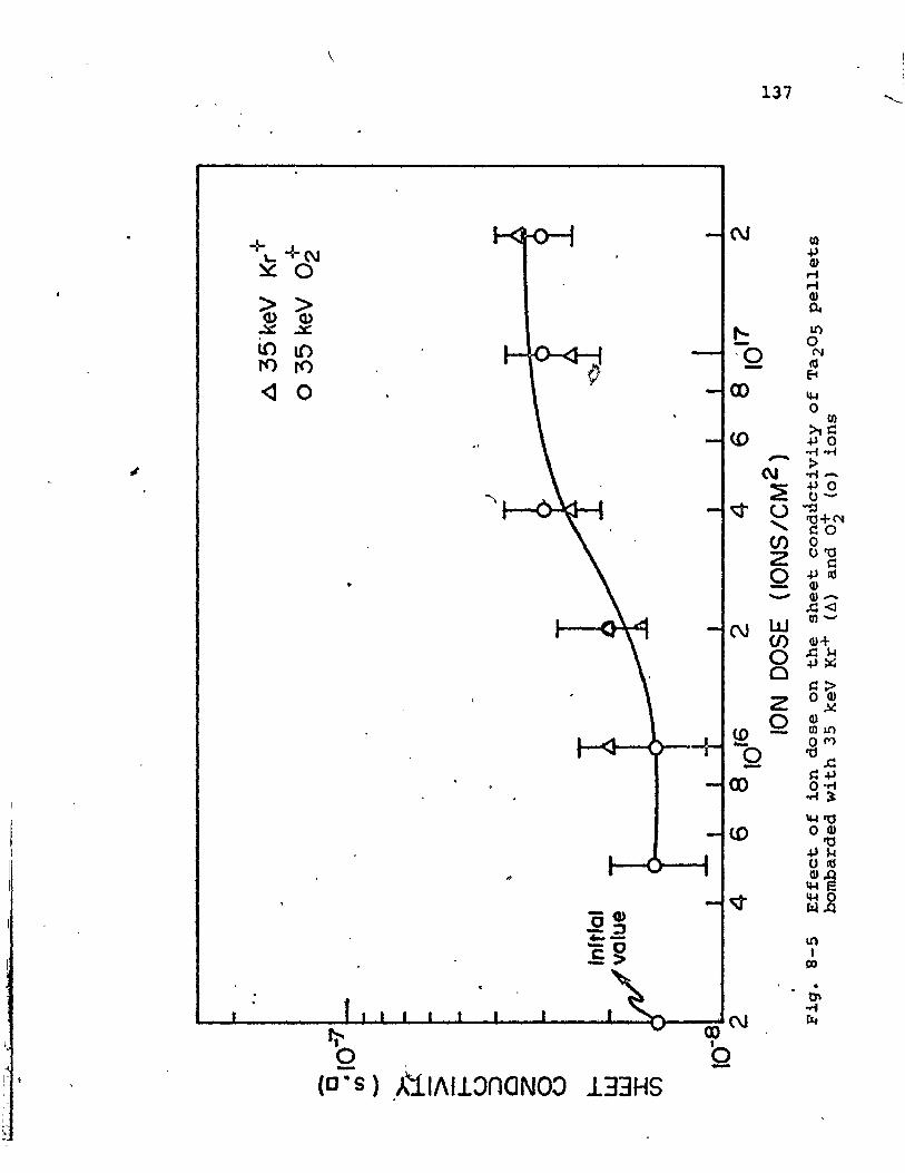
Effect of ion dose on the s~eet conductivityof bombaraed Ta20S pellets
Transmission electron microscopy of anodicTa20S films/-before and after bombardment
PAGE
129
130
132
134
137 .
139
\ .
TABLENO.
1-1
2-1
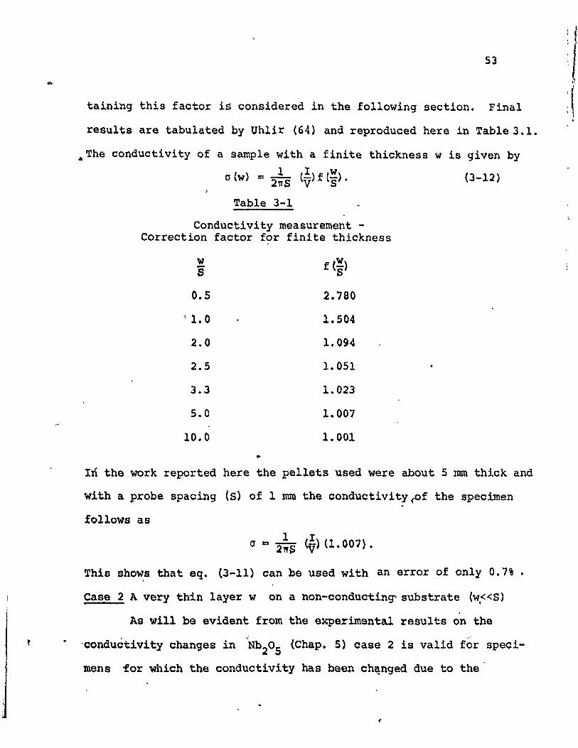
3-1
3-2
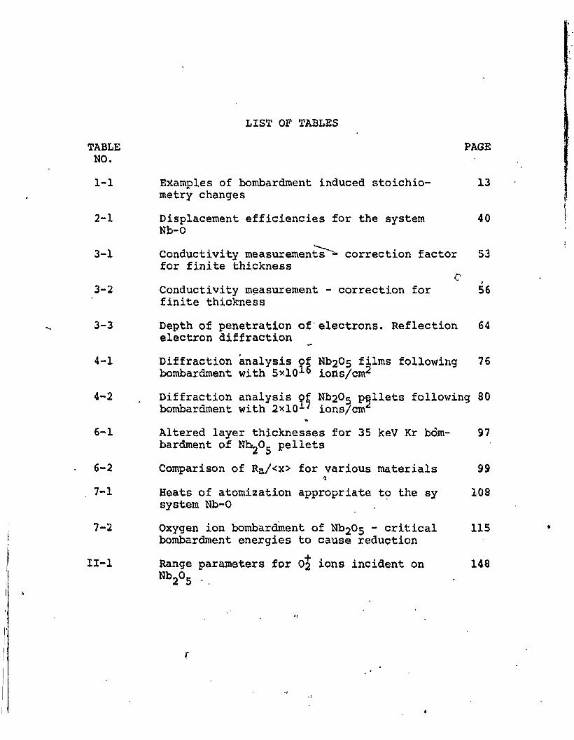
LIST OF TABLES
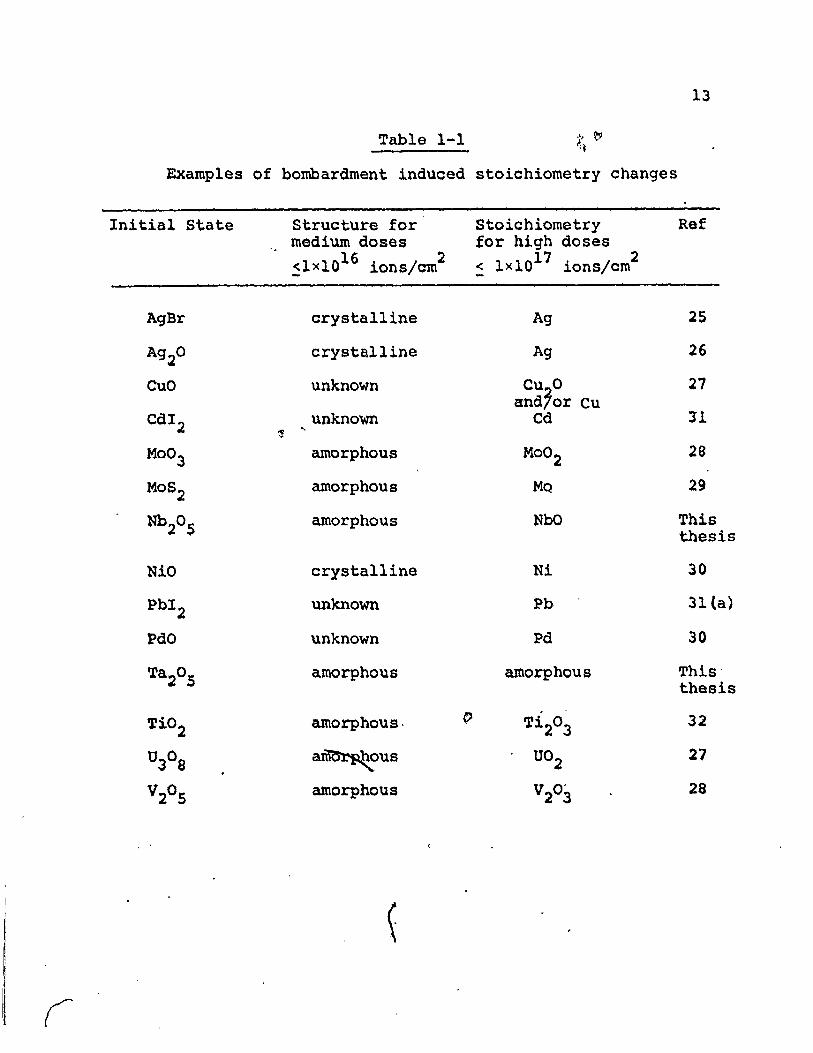
Examples of bombardment induced stoichiometry changes
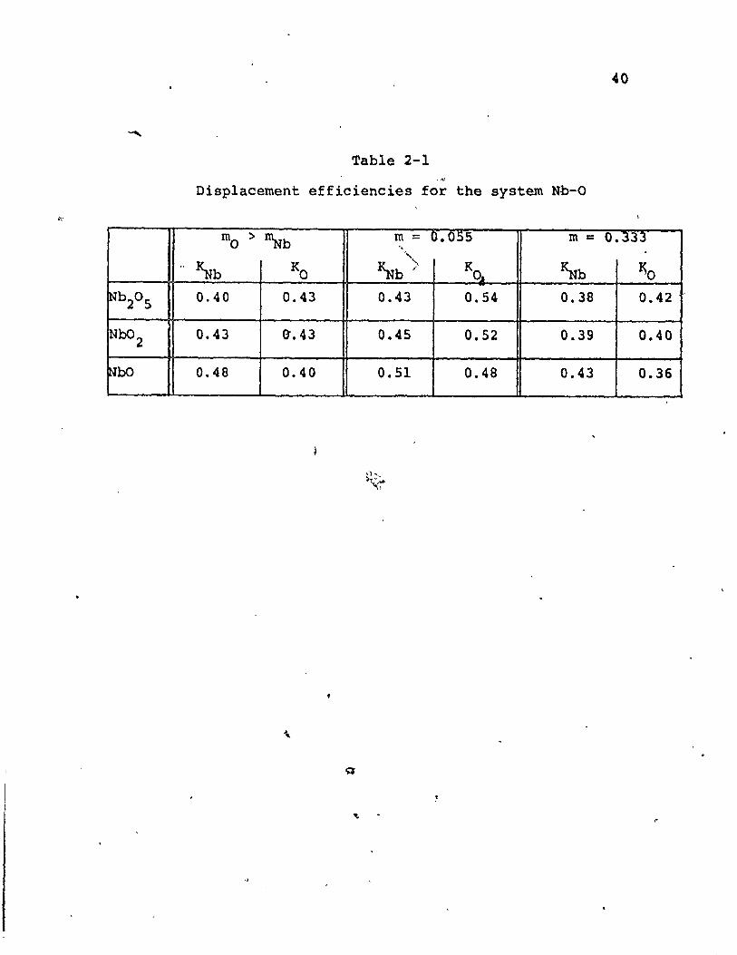
Displacement efficiencies for the systemNb-o
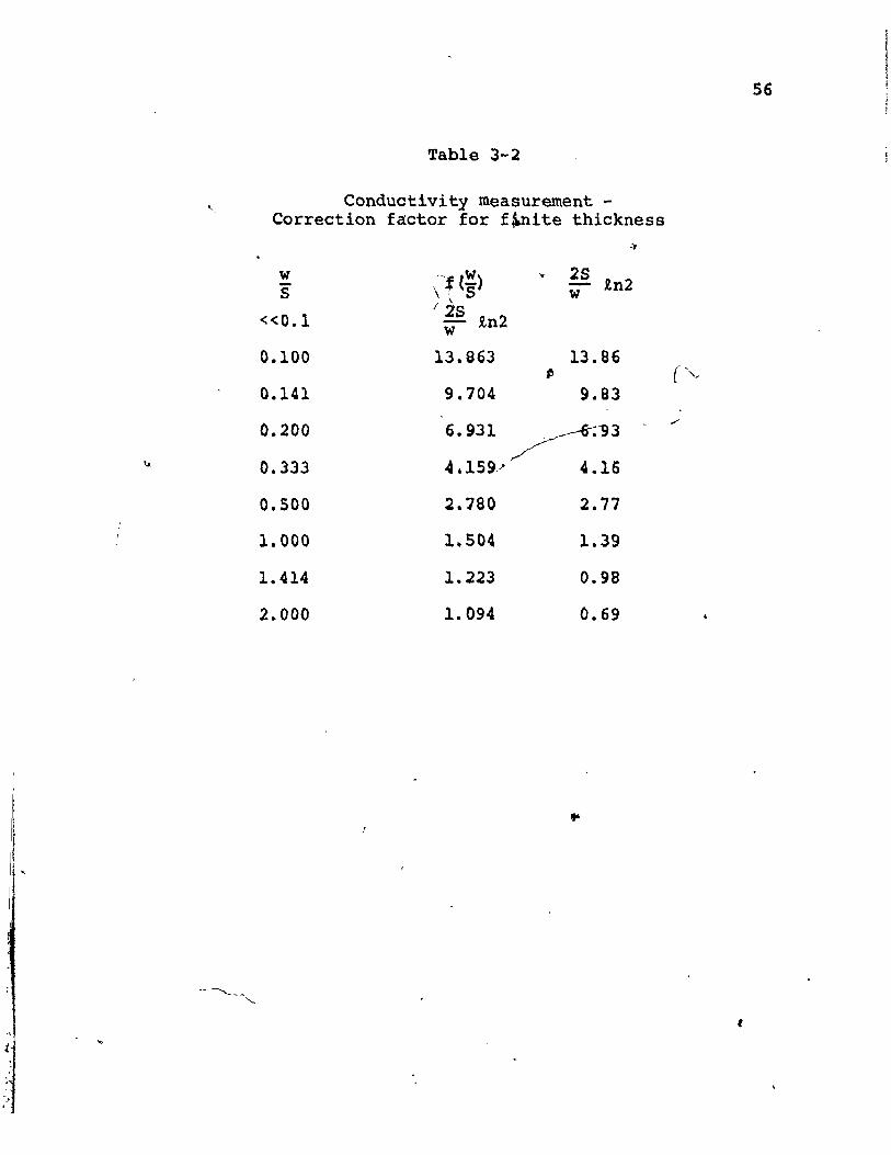
Conductivity measuremen~ correction factOrfor finite thickness
Conductivity m~asurement - correction forfinite thickness
PAGE
13
40
53
>S6
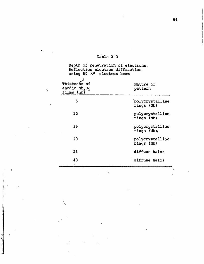
3-3 Depth of penetration of'electrons. Reflection 64electron diffraction
4-1 Diffraction analysis of N020S films following 76bombardment with Sxl016 ions/cm2
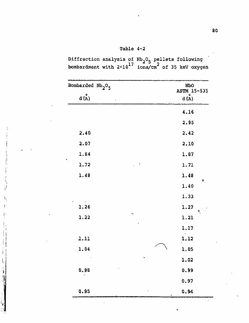
4-2 Diffraction analysis ~; N020S p~llets following 80bombardment with 2xlO ionslem
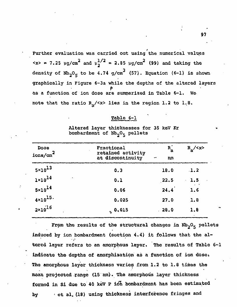
6-1
6-2
7-1
7-'2
11-1
Altered layer thicknesses for 35 keV Kr bombardment of N~OS pellets
Comparison of Ra/<x> for various materials~
Heats of atomization appropriate t~ the sysystem Nb-O
Oxygen ion bombardment of Nb20S - criticalbombardment energies to cause reduction
Range parameters for oi ions incident onNb20S
r
.,
97
99
1,08
115
148
•
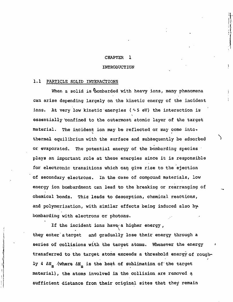
CHAPT~ 1
INTRODUCTION
1.1 PARTICLE SOLID INTERACTIONS
When a solid is ~ombarded with heavy ions, many phenomena
can arise depending largely on the kinetic energy of the incident
ions. At very low kinetic 'energies (~5 eV) the interaction is
essentially ~onfined to the outermost atomic layer of the target
material. The incident ion may be reflected or may come into.~ .
thermal equilibrium with the surface and subsequently be adsorbed.or evaporated. The potential energy of the bombarding species .
plays an important role at these energies since it is responsible~
for electronic transitions which ca~ give rise to the ejection
of secondary electrons. In the case of compound m~terials, low
energy ion bombardment can lead to the breaking or rearranging of
chemical bonds. This leads to desorption, chemical reactions,
and polymerization, with similar effects being induced also b~
bombarding with electrons or photons.
If the in:ident ions hav~a higher energy ,
theyenter'atarget and gradually lose their energy through a
series of collisions with the target atoms. Whenever the energy ~
transferred to the target atoms exceeds a threshold energy of rough-I
1y 4 AHs ·(where AHs is the he~t of s~blimation of" the t~rget
material), the atoms involved in the collision are removed ~
SUfficient distance from their originaf sit~s that they remain


![Sputtering: survey of observations and derived principles papers/Baragiola [r] review sputtering...Sputtering: survey of observations and derived principles By Ra´ul A. Baragiola](https://img.dokumen.tips/doc/110x75/5af974577f8b9abd588ce807/sputtering-survey-of-observations-and-derived-papersbaragiola-r-review-sputteringsputtering.jpg)