Embed Size (px)
Citation preview

U.P.B. Sci. Bull., Series C, Vol. 78, Iss. 4, 2018 ISSN 1454-2358
PREDICTING THE DYNAMIC PERFORMANCE OF THE
FUEL INJECTORS BY NUMERICAL SIMULATION
Daniela VASILIU1, Georgiana Claudia VASILIU2,
Andrei RĂDULESCU3, Toma COJOCARU GREBLEA4
The paper presents the dynamic analysis of the modern automotive
electrohydraulic common rail fuel injection by numerical simulation. The dynamic
performances of the classical injectors, based on solenoid actuators, are compared
with the new generation ones which use piezo ceramic actuators. The numerical
simulations results of Simcenter Amesim language are compared with the
experimental ones, performed by the certified manufacturers. The measured cyclic
mass of the injected fuel and the simulated one are found in good agreement.
Keywords: Electrohydraulic fuel injection systems, solenoid and piezo ceramic
actuators, numerical simulation
1. Structure of the common rail fuel injection systems
The main tools of the mechatronics are widely used in the design of the fuel
injection system for Diesel engines working in high pressure ranges up to 2000 bar
(Figs. 1 and 2). The same concept has been used successfully promoted for gasoline
engine injection systems for pressures up to 200 bar [1…10]. The structure of these
last systems is almost identical to that of the Diesel injection ones, except the
number of stages of the injectors.
From a hydraulic point of view, a solenoid injector (Fig. 3) is a two-stage
servo valve, with a smooth and stabile steady state characteristics connecting the
energizing time and the fuel injected quantity (Fig. 4). The overall dynamic stability
of the engine is improved by the aid of an electrohydraulic proportional metering
valve, with the quasilinear steady state characteristics from Fig. 5. The time
correlation between the solenoid current [A], the injection rate [g/s], and the needle
lift [1/100 mm] for two series of injectors is presented in Fig. 6. The good following
accuracy of the digital input signal by the solenoid allows 4…9 partial injections
on every piston stroke.
1 Prof., M.E., PhD, Power Engineering Faculty, University POLITEHNICA of Bucharest, Romania,
e-mail: [email protected] 2 Lecturer, M.E., PhD, Power Engineering Faculty, University POLITEHNICA of Bucharest,
Romania 3 Technical Expert, A.E., M.Sc., Porsche Romania 4 PhD student, A.E., M.Sc., Power Engineering Faculty, University POLITEHNICA of Bucharest,
Romania

174 Daniela Vasiliu, Georgiana Claudia Vasiliu, Andrei Rădulescu, Toma Cojocaru Greblea
Fig. 1. Structure of a typical common rail fuel injection for Diesel engines. (Source: BOSCH)
.
Fig. 2. Overall view of a typical common rail system injection for Diesel engines.
Fig. 3. Main sections of a EURO 4 BOSCH solenoid injector.

Predicting the dynamic performance of the fuel injectors by numerical simulation 175
Fig. 4. The steady state characteristics of a solenoid injector.
.
Fig. 5. Steady state characteristics (Flow-Current) of a fuel metering valve.
.
Fig. 6. Typical parameters of a common rail fuel injection sequence.
The optimized injection map (Fig. 7) creates the possibility of a significant
reduction of the emissions from the exhausted gases, and improves the engine
power performances, helped by the huge progress in the field of the automotive
Electronic Control Units, running embedded software.

176 Daniela Vasiliu, Georgiana Claudia Vasiliu, Andrei Rădulescu, Toma Cojocaru Greblea
Fig. 7. Typical optimized injection map of a common rail fuel injection system.
2. Simulation of a single solenoid injector operating in ideal conditions
The schematic layout of a common rail system, presented in Fig. 8, suggests
the above steps in the development of a new system for a given engine. The
optimization of a common rail injection system needs in the first stage a deep
knowledge of the individual behavior of an injector running in ideal conditions:
constant environmental temperature, constant supply pressure from the common
rail, constant fuel cavitation behavior etc.
Fig. 8. Schematic layout of the injection system.
The wide range of the operation temperature needs a deep study of all the
system components. The injectors have to be tested in a refrigerating room at low
temperatures, and in a hot room at the extreme operating temperature. This huge
amount of preliminary works leads to the optimal choice of all dimensions,
clearances, and finally - to the controller tuning. Due to the high operation pressure,
the fuel compressibility becomes a dominant property in all the injection systems,
together with the fluid viscosity. Both properties are leading to cavitation problems,
regarding especially the metering small orifices. The fatigue of materials is also an

Predicting the dynamic performance of the fuel injectors by numerical simulation 177
important research field. The numerical simulations in batch can cut a lot of time
from this long process. The Simcenter Amesim simulation model of a solenoid
injector is presented in Fig. 9 [11, 12]. A detail of the studied injection nozzle is
presented in Fig. 10. The next Figs. (11…21) can create a realistic image of the
operation parameters of some major injector components.
Fig. 9. Simulation model of a solenoid injector constant pressure supplied.
The main simulation parameters of the studied case are the common ones.
a) Ball poppet with conical seat: seat diameter: 0.75 mm; seat semi-angle: 57.5
degree; ball diameter: 1.4 mm; mass: 0.003 kg; maximum flow coefficient: 0.6;
higher displacement limit: 52 µm; equivalent orifices diameter of the input strainer:
1.2 mm; control orifice diameter: 0.28 mm; input orifice diameter: 0.31 mm;
b) Linear magnetic transducer: air gap: 0.053 mm; number of coil turns: 30; winding
resistance: 0.6 Ohm; supply voltage: 12 V;
c) Injector nozzle (Fig. 10): needle valve mass: 0.007 kg; diameter of poppet: 2 mm;
seat half angle: 28 degrees; needle cone half angle: 30 degrees; diameter of sac
chamber: 1 mm; sac volume: 0.2 cm3; number of orifices: 6; equivalent orifice
diameter: 0.12 mm; flow coefficient into maximum cavitation for orifices: 0.8;
maximum flow coefficient for cones: 0.75; d) control piston diameter / mass: 4.3
mm / 30 mm; average clearance on diameter: 3 µm; rod diameter: 3 mm; spring

178 Daniela Vasiliu, Georgiana Claudia Vasiliu, Andrei Rădulescu, Toma Cojocaru Greblea
stiffness: 13 N/mm; spring pretension: 30 N; average supply pressure of the
injector: 1000 bar.
Fig. 10. Main section of the injection nozzle with sac volume (damper).
In a typical steady-state operating regime, the solenoid driver is fed by rectangular
input signals (Fig. 11), generating the input voltage signals indicated in Fig. 12, and
the current inputs from Fig. 13.
Fig. 11. The input relative signal applied to the solenoid driver of the injector.
.
Fig. 12. Voltage applied to the solenoid coil.
.
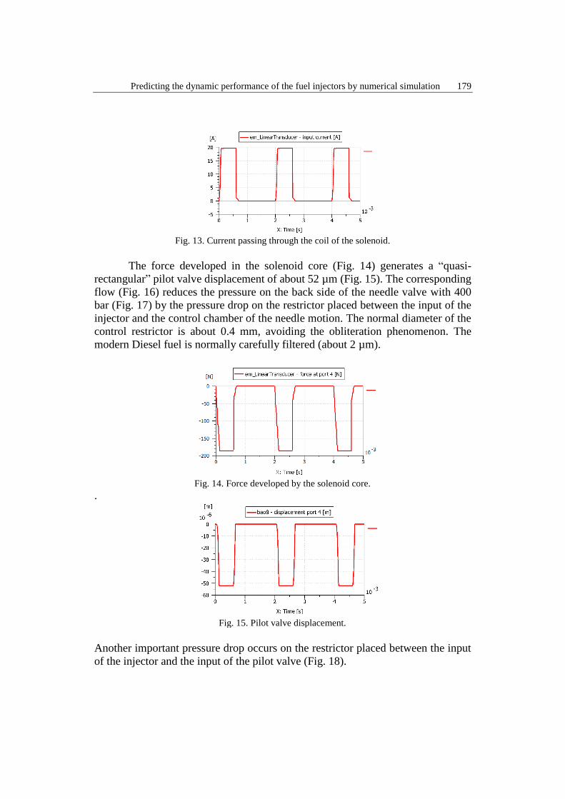
Predicting the dynamic performance of the fuel injectors by numerical simulation 179
Fig. 13. Current passing through the coil of the solenoid.
The force developed in the solenoid core (Fig. 14) generates a “quasi-
rectangular” pilot valve displacement of about 52 µm (Fig. 15). The corresponding
flow (Fig. 16) reduces the pressure on the back side of the needle valve with 400
bar (Fig. 17) by the pressure drop on the restrictor placed between the input of the
injector and the control chamber of the needle motion. The normal diameter of the
control restrictor is about 0.4 mm, avoiding the obliteration phenomenon. The
modern Diesel fuel is normally carefully filtered (about 2 µm).
Fig. 14. Force developed by the solenoid core.
.
Fig. 15. Pilot valve displacement.
Another important pressure drop occurs on the restrictor placed between the input
of the injector and the input of the pilot valve (Fig. 18).

180 Daniela Vasiliu, Georgiana Claudia Vasiliu, Andrei Rădulescu, Toma Cojocaru Greblea
Fig. 16. Flow rate passing through the pilot valve.
Fig. 17. Pressure drop on the control restrictor placed at the input of the injector.
Fig. 18. Pressure drop on the pilot valve restrictor.
The displacements of the needle (Fig.19) generates the fuel injections from Fig. 20.
Fig. 19. Displacement of the needle of the injector.

Predicting the dynamic performance of the fuel injectors by numerical simulation 181
The fuel flow rate injected in the cylinder (Fig. 20) and the corresponding
transferred mass (Fig. 21) can be correlated with the torque and speed needs of the
engine.
Fig. 20. Flow rate delivered by the injector to the engine cylinder.
Fig. 21. Mass introduced by the injector in the engine cylinder.
A successful tuning of a common rail fuel injection needs a huge amount of
simulation sessions, which alternate with software validation by HIL simulations.
A simple way of reducing the overall computation time is the Discrete Partitioning
Technique. The principle of this procedure is to divide the complete injection
system into smaller subsystems and perform a co-simulation between the master
and slave systems. This allows to each subsystem to be solved independently from
one another. Each subsystem has its own integrator. Consequently, the time steps
are typical of the local subsystem only. The division of the complete set of equations
in subsystems having smaller Jacobians saves time under the condition of using a
high-speed bus. This takes advantage of multicore PC’s since each subsystem runs
independently on different cores. An overall simulation network used for discrete
partitioning integration is presented in Fig. 22. The study of the whole system
reveals the important role of the high number of nonlinear components, leading to
a “rain” of pressure waves which can strongly disturb the overall steady state of the
engine operation. The length and stiffness of all the pipes becomes very important
from this point of view. Nothing is happening in a smooth manner inside the system!

182 Daniela Vasiliu, Georgiana Claudia Vasiliu, Andrei Rădulescu, Toma Cojocaru Greblea
Fig. 22. Overall simulation network used for Discrete Partitioning Integration.
The simulation results show the high precision of the injection timing, rate and
duration offered by a two-stage solenoid actuated common rail Diesel fuel injection
systems. However, some better results can be obtained by replacing the solenoid
actuator by a piezo ceramic one.
3. Simulation of a single piezo injector operating in ideal conditions
The increasing requirements for reducing the engines emissions led to the
replace of the solenoid actuator of the pilot valve by a piezo ceramic one. Actuators
based on piezoelectric ceramic materials prime movers (or piezo actuators) are
finding broad acceptance in applications where precision motion and/or high
frequency operation is required.
Piezo actuators can produce smooth continuous motion with resolution
levels at the nanometer and sub-nanometer level. This property makes them useful
in precision positioning and scanning systems. The very fast response time, wide
operating bandwidth, and high specific force may be beneficial for applications in
fluid valves control, optical scanning, vibration isolation, and precision machining
[1]. With proper design, the piezo actuators have performance attributes and
properties that can be valuable in precision positioning, vibration control, and

Predicting the dynamic performance of the fuel injectors by numerical simulation 183
scanning applications. Smooth, precise motion from the sub-nanometer to multiple-
millimeter level is possible with a variety of solid-state actuation/amplification
mechanisms. The application area of these actuators extends continuously in the
field of high pressure flow control valves. A typical example is presented in Fig.
23.
Fig. 23. Cut view of a modern piezo BOSCH injector.
The following figures contain the main results of the numerical simulations
performed by Simcenter Amesim for a typical piezo inline injector developed by a
few companies for high-quality Diesel engines [1], [8], [9], [10]. A complete
mathematical model of such an automotive component is presented in Fig. 24.
The piezoelectric actuator was designed considering a ball pilot valve of 1.5
mm diameter with a sharp seat of 1.0 mm diameter. The target is to obtain a force
of about 150 N needed for compressing the spring of the control valve, and a stroke
of about 36 μm, using a voltage power supply of 100 V.
This result can be reached using a stack of 700 wafers with a thickness of
0.05 mm and an area of 25 mm². Such a choice allows reasonable dimensions of
the square piezo stack (5 mm x 5mm x 35 mm). A restrictor of 0.2 mm diameter
was introduced at the input of the control chamber of the needle. Another 0.3 mm
diameter restrictor was considered between the control chamber and the pilot valve.
Some typical results concerning the injector dynamics are presented in Figs.
25...34: from the input voltage signal, current output of the source, and force
developed by the piezo actuator to the transferred fuel mass to the cylinder. Taking
into account the high speed response capability of the piezo actuator, a ramp type
input signal of 0.5 ms was considered. The same time was used for the negative
slope ramp at the end of the control signal.

184 Daniela Vasiliu, Georgiana Claudia Vasiliu, Andrei Rădulescu, Toma Cojocaru Greblea
Fig. 24. Simcenter Amesim model for a piezo ceramic actuated injector.
.
Fig. 25 Input voltage signal used for the opening and the closing of the pilot valve.
.
Fig. 26. Current output of the controlled voltage source.

Predicting the dynamic performance of the fuel injectors by numerical simulation 185
.
Fig. 27. Force applied by the piezo actuator on the pilot valve spring.
.
Fig. 28. Ball displacement during a control cycle.
.
Fig. 29. Velocity of the ball poppet during a control cycle.
.
Fig. 30. Overall force on the injector needle.

186 Daniela Vasiliu, Georgiana Claudia Vasiliu, Andrei Rădulescu, Toma Cojocaru Greblea
Fig. 31. Needle displacement in a control cycle (maximum 0.19 mm).
.
Fig. 32. Pressure variation at the input of the nozzle.
.
Fig. 33. Pressure in the nozzle intermediate chamber.
.
Fig. 34. Transferred mass by the injector to the engine cylinder running at 40 bar.

Predicting the dynamic performance of the fuel injectors by numerical simulation 187
5. Conclusions
The simulation results show the capability of the electrohydraulic two stage
injectors to supply properly any automotive engine. The injected fuel amount can
be tuned with the engine demands [11…22], starting from a precise simulation of
all the operation regimes. Some new concepts have to be underlined in order to
explain the high level performances, and reliability of such a two-stage piezo flow
metering injection valve. First of all, the standard ball pilot valve used in the
solenoid injectors was replaced by a conical poppet uncompensated pilot valve.
This type of valve is more reliable, and offers a better tightness. A coupled module
between the piezo actuator and the needle is needed for thermal reasons. The main
problem of this type of injectors remains the piezo material thermal stability.
Another problem is the high voltage source (about 100 V) needed for exciting the
piezo stack. However, the increasing of the injections numbers on every piston
stroke (6…9) improves the environmental performances of all types of thermal
engines, and allows a better prediction of their dynamic behavior.
The solenoid injectors were also continuously improved by increasing the
solenoid power, using a guided poppet valve instead a ball poppet, and reducing the
needle diameter and weight [3, 8 and 23]. These changes allowed the reach of the
Euro 6 emissions standard [23]. Fig. 35 presents a realistic prediction of the steady-
state individual injection performance, used in the synthesis of the injection map of
an engine, confirmed by high accuracy test benches.
Fig. 35. The overall injection performance of a modern common rail system

188 Daniela Vasiliu, Georgiana Claudia Vasiliu, Andrei Rădulescu, Toma Cojocaru Greblea
The above results confirm the utility of the numerical simulation in any industrial
design process.
R E F E R E N C E S
[1]. Robert Bosch GmbH, Diesel Engine Management, Wiley, 4th Edition, 2005.
[2]. Aird F., Bosch Fuel Injection Systems, HP Books, 2001.
[3]. Breitbach H. Fuel Injection Systems Overview, Delphi Corporation, 2002.
[4]. Jost K., New common-rail diesels power Alfa's 156, Automotive Engineering, pp 36-38,
January 1998.
[5]. Knecht W., Some historical Steps in the Development of the Common Rail Injection Systems,
Trans. Newcomen Soc., 74/2004, pp 89-107.
[6]. Petruzzelli A.M. A Story of Breakthrough. The Case of Common Rail Development, 35th
DRUID Celebration Conference, Barcelona, Spain, 17-19 June 2013.
[7]. Smil V. Prime Movers of Globalization: The History and Impact of Diesel Engines and Gas
Turbines. MIT Press, Cambridge, MA, 2010.
[8]. www.delphi.com
[9]. www.siemens.com
[10]. www.continental-automotive.com
[11]. *** Siemens PLM Software, Simcenter Amesim R13, Leuven, 2013.
[12]. Vasiliu N., Vasiliu D., Călinoiu C., Puhalschi R., Simulation of Fluid Power Systems with
Simcenter Amesim. CRC Press, Taylor & Francis Group, Boca Raton, 2018.
[13]. www.dynamic-structures.com
[14]. https://au.bosch-automotive.com/en/parts_and_accessories/motor_and_sytems/diesel/
[15]. http://www. lmsimagine.lab/ame_dir/demo/Solutions/Automotive/Powertrain/Engine/
[16]. http://www.amtgarageforum.nl/public/topics/603481-funtion_hdi_siemens.pdf
[17]. https://www.elsevier.com/books/fuel-systems-for-ic-engines/978-0-85709-210-6
[18]. https://www.dieselnet.com/tech/diesel_fi_common-rail.php
[19]. http://pmmonline.co.uk/technical/common-rail-diesel-fuel-systemissue-peugeot-307-hdi
[20]. http://www.repairmanual.net.au/car-repair/common-rail-diesel
[21]. Hardenberg H., Die geometrischen Strömungsquerschnitte von Lochdüsen für Direktein
spritzmotoren, MTZ 45 (1984) 10, S. pp 427-429, 1984.
[22]. De Groen O., Kok D., Rechenprogramm zur Simulation von Hochdruckeinspritzsystemen
für Nutzfahrzeuge, Motortechnische Zeitschrift MTZ – 57, 1996.
[23]. *** Volkswagen AG, The 1.4 l 3-cylinder TDI Engine in the EA288 Diesel Engine Family,
After Sales Qualification Service Training VSQ-2, Wolfsburg, Germany, 2014.


![[DESIGN] Piezo-Piezo to Pie](https://img.dokumen.tips/doc/110x75/5571f8bb49795991698df909/design-piezo-piezo-to-pie.jpg)