Embed Size (px)
Citation preview

Page 1 of 6
Florida Department of Transportation
Technical Special Provisions
for
PRECAST PRESTRESSED POST-TENSIONED
CONCRETE PAVEMENT
FPID 422024-2-52-01
The official record of this package is the electronic file signed and sealed under Rule 61G 15-23.003, F.A.C.
Prepared by: Hussam Fallaha, PE
Florida Department of Transportation
Structures Design Office
605 Suwannee Street MS-33
Tallahassee, FL32399-0450
May 25, 2010

Page 2 of 6
T 1-1 DESCRIPTION
Construct the precast prestressed concrete pavement as shown in the plans according to the applicable
sections of the Florida Department of Transportation Standard Specifications for Road and Bridge
Construction 2010, and this technical special provision.
Fabricate, store, transport and install precast/prestressed concrete pavement, pretensioned transversely
and post tensioned longitudinally. Supply and pour the keyways gout. Supply, install all the post
tensioning systems; and apply the post tensioning. Grout all the post-tensioning systems. Supply and
install expansion joints.
The term "panel" shall refer to individual precast concrete panels, including interior Panels or end
panels. The term "slab unit" shall refer to a post-tensioned section of precast panels between the
expansion joints.
T 2-1 PANEL FABRICATION
Fabricate the panels according to the plans, section 450 and this technical special provision. Form the
end panels and interior panels with shear keys and block-out as shown in the plans and to the
tolerances shown in Table 1.
Place smooth Glass Fiber Reinforced Polymer (GFRP) dowels at the expansion joints ends of the end
panels as shown in the plans. Place pockets in the ends of the adjacent panels to receive these dowels.
Ensure that these dowels are placed parallel to the surface of the panel and normal the expansion joint
to facilitate the slab movement without damage.
Install the post-tensioning system ducts, anchorages and block-outs according to the approved shop
drawings.
Prior to fabrication, submit shop drawings to the engineer for approval showing the end panels and
the interior panels. Show the post- tensioning system ducts and anchorages and the dowels at the
expansion joints on the shop drawings.
Prior to shipping, blast the panels’ key ways and block-outs surfaces to insure that the keyways and
the block-out surfaces are clean and free of all laitance and form release oils.
T 2-1.1 Forms
Use metal side and bottom forms sufficiently rigid to produce panels that meet the tolerance
requirements shown in Table 1. Wood forms are NOT permitted.
T 2-1.2 Storage
Panel deformation during storage may prevent the ducts from matching during installation.
Therefore, Store Panels in such a way that deformations do not exceed the acceptable tolerances.

Page 3 of 6
T 2-1.3 Tolerance
TABLE 1: TOLERANCES FOR PRECAST PANELS
Length (parallel to the roadway centerline) +/- 1/8”
Width (normal to the roadway centerline) +/- 1/4”
Nominal Thickness +/- 1/8”
Squareness (difference in measurement from corner to corner cross
top surface, measured diagonally)
+/- 1/4”
Horizontal Alignment (upon release of stress)–Deviation from
straightness of mating edge of panels
+/- 1/8”
Vertical Alignment–Camber (upon release of stress) +/- 1/8”
Deviation of ends (horizontal skew) +/- 1/8”
Deviation of ends (vertical batter) +/- 1/8”
Keyway Dimensional Tolerance +/- 1/16”
Position of Strands +/- 1/8” Vertical
+/- 1/4” Horizontal
Position of post-tensioning ducts at mating edges
+/- 1/8” Vertical
+/- 1/8” Horizontal
Straightness of post-tensioning ducts +/- 1/4” Vertical
+/- 1/4” Horizontal
Vertical Dowel Alignment (parallel to bottom of panel) +/- 1/8”
Horizontal Dowel Alignment (normal to expansion joint) +/- 1/8”
Dowel Location (deviation from shop drawings)
+/- 1/4” Vertical
+/- 1/4” Horizontal
Dowel Embedment (in either side of expansion joint) +/- 1/4”
Position of lifting anchors +/- 3”
Position of non-prestressed reinforcement, including tie-bars
(unless tolerance otherwise provided in plans)
+/- 1/4”
Straightness of expansion joints +/- 1/4”
Initial width of expansion joints +/- 1/8”
Dimensions of blockouts/pockets +/- 1/8”
Fabricate the precast panel to meet the required tolerance listed in table 1.
Page 4 of 6
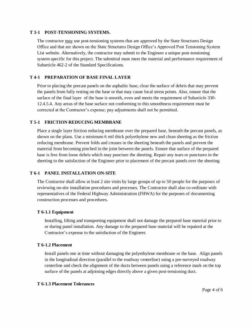
T 3-1 POST-TENSIONING SYSTEMS.
The contractor may use post-tensioning systems that are approved by the State Structures Design
Office and that are shown on the State Structures Design Office’s Approved Post Tensioning System
List website. Alternatively, the contractor may submit to the Engineer a unique post-tensioning
system specific for this project. The submittal must meet the material and performance requirement of
Subarticle 462-2 of the Standard Specifications.
T 4-1 PREPARATION OF BASE FINAL LAYER
Prior to placing the precast panels on the asphaltic base, clear the surface of debris that may prevent
the panels from fully resting on the base or that may cause local stress points. Also, ensure that the
surface of the final layer of the base is smooth, even and meets the requirement of Subarticle 330-
12.4.5.4. Any areas of the base surface not conforming to this smoothness requirement must be
corrected at the Contractor’s expense; pay adjustments shall not be permitted.
T 5-1 FRICTION REDUCING MEMBRANE
Place a single layer friction reducing membrane over the prepared base, beneath the precast panels, as
shown on the plans. Use a minimum 6 mil thick polyethylene new and clean sheeting as the friction
reducing membrane. Prevent folds and creases in the sheeting beneath the panels and prevent the
material from becoming pinched in the joint between the panels. Ensure that surface of the prepared
base is free from loose debris which may puncture the sheeting. Repair any tears or punctures in the
sheeting to the satisfaction of the Engineer prior to placement of the precast panels over the sheeting.
T 6-1 PANEL INSTALLATION ON-SITE
The Contractor shall allow at least 2 site visits by large groups of up to 50 people for the purposes of
reviewing on-site installation procedures and processes. The Contractor shall also co-ordinate with
representatives of the Federal Highway Administration (FHWA) for the purposes of documenting
construction processes and procedures.
T 6-1.1 Equipment
Installing, lifting and transporting equipment shall not damage the prepared base material prior to
or during panel installation. Any damage to the prepared base material will be repaired at the
Contractor’s expense to the satisfaction of the Engineer.
T 6-1.2 Placement
Install panels one at time without damaging the polyethylene membrane or the base. Align panels
in the longitudinal direction (parallel to the roadway centerline) using a pre-surveyed roadway
centerline and check the alignment of the ducts between panels using a reference mark on the top
surface of the panels at adjoining edges directly above a given post-tensioning duct.
T 6-1.3 Placement Tolerances

Page 5 of 6
Align adjacent panels to meet the following tolerances:
Post-tensioning ducts must match with +/-1/4 inches.
Longitudinal +/- 1/8 inches (Deviation of centerline of panel from centerline of roadway).
Transverse +/- 1/8 inches (The width of the shear key should not vary more than 1/8 inches).
T 7-1 TRANSVERSE JOINTS BETWEEN PANELS
After setting the panels and coupling of post-tension ducts, fill the transverse keyway using Non-
shrink grout meeting the requirements of Section 934. Prior to placing the Non-shrink grout ensure
that the concrete surfaces of the keyway are clean and free of debris, soil, laitance or form release
agents.
T 8-1 EXPANSION JOINTS
Construct Expansion Joints according to Section 458. The expansion joints shown in the plans are
considered bridge deck joints “Poured Joints with Backer Rod Systems” . Submit shop drawing to the
Engineer for approval showing the expansion joint material and construction
T 9-1 DOWELS
Place smooth Glass Fiber Reinforced Polymer (GFRP) dowels at the expansion joints as shown in the
plans. Insure that these dowels are placed parallel to the surface of the panel and normal the
expansion joint to facilitate the slab movement without damage. Use dowel expansion caps that
provide a minimum of 1.25 inches of free movement of the dowel end within the expansion cap.
Use polystyrene or other approved material in the joint to form the edge of the slab around the
dowels.
T 10-1 GROUTING TRANSVERSE JOINTS AND POCKETS
Grout all transverse joints and block-outs for post-tensioning anchorages and for dowels using non-
shrink grout that meet the requirement of section 934 of the Standard Specifications and the strength
requirement shown in the plans.
T 11-1 UNDERSLAB GROUTING
If the base is not sufficiently smooth and even or if there are voids under the slab, the Engineer may
require the contractor to grout under the slabs. If underslab grouting is required, do the underslab
grouting after the post-tensioning operation is complete, using non-shrink grout meeting the
requirement of Section 934, and the grouting pressure shall not exceed 5 psi.
T 12-1 FINISHING
Use burlap drag or broom to produce uniform gritty texture on the top surface of the panels. Grind the
concrete slabs in accordance with section 352 of the Standard Specifications.

Page 6 of 6
T 13-1 METHOD OF MEASUREMENT AND BASIS OF PAYMENT
Prestressed pavement shall be measured in square yards of pavement surface area, and payment
shall be made at the contract unit price per square yard for prestressed pavement, complete in place
and accepted. This price and payment shall be full compensation for all material, labor and equipment
necessary to fabricate, deliver, and install the precast pavement slabs as shown in the plans.
Installation of polyethylene friction reducing membrane, grouting of transverse shear keys and block-
outs, installation and stressing of post-tensioning steel, installation of Glass Fiber Reinforced Polymer
(GFRP) dowels at the expansion joints are also included. Materials include all reinforcing steel, pre-
tensioning steel, embedded ducts, hardware, inserts and other materials. Final pay area will be plan
quantity, as detailed on the plans, subject to the provisions of Subarticle 9-3.2.
Item number 450-5 Prestressed Pavement ---- per square yards.
Measurement and payment for grinding the slabs shall be according to Section 352 of the Standard
Specifications.