Embed Size (px)
Citation preview

PRE- FEASIBILITY REPORT
FOR
THE EXPANSION OF SYNTHETIC RESINS MANUFACTURING
INDUSTRY
At
Plot No. 64B & 65C,
KIADB Industrial Area, Tubinakere,
Mandya District
Prepared by:
F- 4, I Floor, Swastik Manandi Arcade,
S. C. Road, Sheshadripuram,
Bangalore - 560 020
Phone: 080-23460102
Email: [email protected]/ [email protected]
Submitted to:
The Member Secretary
SEIAA, Karnataka,
Department of Forest Ecology and Environment,
Room No 709, 7th Floor 4th Gate MS Building,
Bangalore 56001.
APRIL 2018

Asian Polymers Pre-Feasibility Report
CONTENTS
CHAPTER 1-Executive Summery .......................................................................................................... 01-02
CHAPTER 2-Introduction of the Project Background Information ........................................................... 03-06
CHAPTER 3- Project Description ........................................................................................................... 07-42
CHAPTER 4- Site Analysis..................................................................................................................... 43-47
CHAPTER 5- Planning Brief ................................................................................................................... 48-49
CHAPTER 6- Proposed Infrastructure .................................................................................................... 50-51
CHAPTER 7- Rehabilitation & Resettlement Plan .................................................................................. 52-52
CHAPTER 8- Project Schedule & Cost Estimates .................................................................................. 53-53
CHAPTER 9- Analysis of Proposal ......................................................................................................... 54-54
LIST OF TABLES
Table 2.1- Details of Existing and proposed products .................................................................................. 04
Table 3.1- Location details .......................................................................................................................... 07
Table 3.2 Details of existing, proposed & expansion products with capacity ................................................ 12
Table 3.3-Raw Material Details ................................................................................................................... 37
Table 3.4-Water Consumption Details ......................................................................................................... 38
Table 3.5-Power and Energy Requirement .................................................................................................. 39
Table 3.6--Air pollution Details .................................................................................................................... 40
Table 3.7 Hazardous waste management ................................................................................................... 41
Table 4.1-Site co-ordinates ......................................................................................................................... 44
Table 4.2-Claimatic Data ............................................................................................................................. 46
Table 5.1-Census details ............................................................................................................................. 48
Table 5.2-Land use planning ....................................................................................................................... 49
Table 8.1-Project cost ................................................................................................................................. 53
Asian Polymers Pre-Feasibility Report
LIST OF FIGURES
Figure 3.1- Location of project site on google map (5Km radius) ................................................................ 08
Figure 3.2-Location of proposed project plant on the district map ................................................................ 09
Figure 3.2-Plant Layout Plan ....................................................................................................................... 11
Figure 4.1-Shows the location of the plant on the topo-map ........................................................................ 44
Figure 4.2-Annual temperature graph of Mandya ........................................................................................ 47
Figure 4.3-Annual precipitation graph of Mandya ........................................................................................ 47
LIST OF ANNEXURES
Annexure 1 – CFO Compliance ................................................................................................................... 55
Annexure 2 – Onsite Emergency Plan ......................................................................................................... 56

Pre-feasibility Report
1
CHAPTER 1
EXECUTIVE SUMMERY
1. Executive Summery
1.1 Introduction:
M/s Asian Polymers is a proprietorship company and is into the business of manufacturing of synthetic
resins. The existing manufacturing capacity is 6218 MTPA. The industry is operating since 2010, with valid
consent from KSPCB at 64 B & 65 C, KIADB Industrial Area, Tubinakere, Mandya Taluk & District, and
Karnataka State. The land area is 4007 sq mts or 0.99 acres.
1.2 Project Details:
The industry intend for expansion in production capacity of existing products along with two new products.
Presently 6 products are manufacture with combined manufacturing capacity of 6218 MTPA. After
proposed expansion the number of products manufactured will be eight with combined capacity 27,900
MTPA.
i. Water Management:
The water source for the industry is KIADB supply. Water is used for process, softener generation
plant, cooling tower make up, boiler feed & domestic utilities.
The process effluent generated from the process will be evaporated in Forced Evaporation System.
Whereas the waste water from the process is re-cycled. The cooling tower bleed off is being
recycled back, boiler blow down & softener plant waste is being used for on land for gardening.
Domestic Sewage will be disposed to septic tank followed by soak pit.
ii. Air Pollution:
The source of emission is from boiler (i.e wood husk fired boiler-1TPH) & DG Set-62.5 KVA X 1 No.
are provided with stacks of adequate height. APC measures are adequate to control and disperse
the pollutant.

Pre-feasibility Report
2
iii. Solid waste Management:
There is no generation of solid waste from the process, only domestic garbage is the solid waste
generation from the industry. This has being disposed through composting.
iv. Hazardous Waste Management:
The hazardous waste generation from the industry will be stored in safe and scientific manner which
will be disposed to KSPCB authorized agencies only.
Applicability of Environmental clearance:
The Asian Polymers manufactures Synthetic Resins. Synthetic Resins manufacturing activity is listed under
serial No. 5(f) of schedule to the EIA Notification, 2006.
The Asian Polymers being a very small scale industry located in KIADB Industrial Area, Tubinakere,
Mandya District has not obtained Environmental Clearance. However, the plant is following all the pollution
control measures to control water pollution and air pollution and complying with environmental norms with
adequate environmental safeguards. No damage to the environment of what so ever in nature is done due
to the operation of the Asian Polymers. The Karnataka State pollution Control Board is regularly issuing the
Consent to Operate, the present consent is valid for a period up to 30.06.2018 to manufacture 6 products
on campaign basis. The compliance statement of consent is appended as Annexure - 1.

Pre-feasibility Report
3
CHAPTER 2
INTRODUCTION OF THE PROJECT BACKGROUND INFORMATION
2. INTRODUCTION
2(i) Identification of project & project proponent
2.1 Identification of Project
Asian Polymers is a proprietorship company and is into the business of manufacturing of synthetic resins.
The total manufacturing capacity is 6218 MTPA. The industry is operating since 2010, with valid consent
from KSPCB at 64 B & 65 C, KIADB Industrial Area, Tubinakere, Mandya Taluk & District, and Karnataka
State. The land area is 4007 sq mts or 0.99 acres. The consent for operation for manufacturing of synthetic
resins from KSPCB is valid up to 30.06.2018. The company has the Authorization under the Hazardous
Waste (Management, Handling and Transboundary Movement) Rules, 2008. With validity upto 30.06.2020.
The location of the industry is in designated industrial area, well connected between Bangalore and Mysore
by railways and road transport facility.
2.2 About the Project Proponent
Mr. Tom Mathew. BSc (Chemistry) is the proprietor of Asian Polymers. He is a young entrepreneur from
Kerala State., he is 39 years old. He is having one more unit at Kerala, in the name and style, M/s Asian
Polymers, Keeriyad, Kattampally, Kannur District, Kerala.
2(ii) Brief description of the nature of the project
Asian Polymers situated in KIADB Industrial Area of Tubinakere, Mandya is a small scale industry. As per
the market demand industry propose to change the product mix and also add on two additional resins.
The list of existing, proposed expansion product and total product after expansion are given in below said
table;
Pre-feasibility Report
4
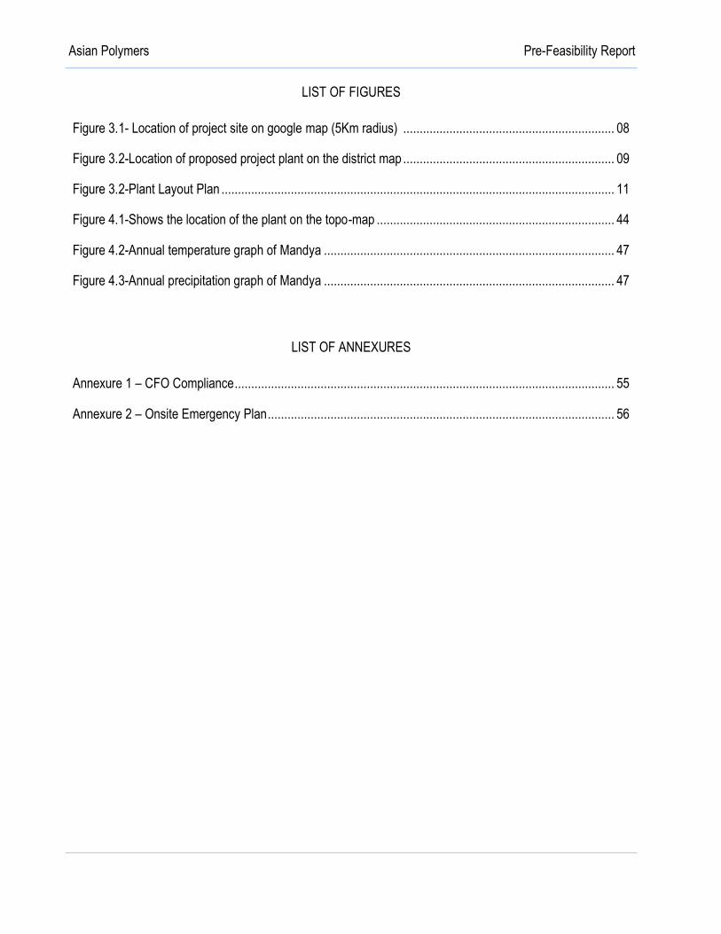
Table 2.1: Details of existing & expansion products
Sl
#
Product Name Production Capacity in MTPA*
Existing Total (after expansion)
1 Phenol Formaldehyde Resin powder 36 900
2 Phenol Formaldehyde Liquid Resin (73%) 12 2100
3 Phenol Formaldehyde Liquid Resin (80%) 1150 2100
4 Phenol Formaldehyde Liquid Resin (50%) 900 7200
5 Urea Formaldehyde Resin 65% 120 2400
6 Urea Formaldehyde Resin 50% 4000 7200
7 Phenol Formaldehyde Liquid Resin (80%) - 3000
8 Phenol Formaldehyde Liquid Resin (76%) - 3000
Total 6218 27900
* The production will be based on the product demand and it will be on campaign basis. The industry
manufactures two products at a time in a day.
2(iii) Need for the project & its importance to region
The requirements of the various synthetic resins are increasing day by day in various applications such as
plywood, grinding wheel, brake lining and clutch lining in foundries in corks, in shell moulding, in lamp
camping etc. Thus, company has planned to manufacture synthetic resins as mentioned above to meet the
market requirement and demand. The present project of the company for manufacture of synthetic resins is
surly feasible. Finished products will be sold in domestic market. The present project will also contribute the
revenue of the central and state exchequer by means of payment of various taxes applicable to the similar
types of industries.
2(iv) Demand- supply gap
Demand of synthetic resins in the country is increasing day by day. Synthetic resins are also used in
various applications such as plywood, grinding wheel, brake lining and clutch lining in foundries in corks, in
shell moulding, in lamp camping etc. The growth and demand of the ply board largely play an important role
for the growth and demand of synthetic resins. Since last 2-3 years the Plywood, Laminate, Fabric items,
Steel Industries and Engineering products are growing at a remarkable pace, which in turn increased the
demand of various industrial inputs. The market demand of synthetic resins is also seeing the upward
growth tendency hence there is a scope for further investments in this sectors, especially because the

Pre-feasibility Report
5
existing capacities may not be sufficient to meet the new demand. Moreover, the recently invented process
technology for better quality product also needs further investments and shall open new markets. Indian
plywood industry is valued at Rs. 5,000 crores. The industry is growing at rapid pace of 10-20% per annum.
Approximately 600 units are currently functioning all over the country. There is tremendous growth
potential. Panel and plywood products are the main wood products in India. Product categories include
veneer sheets, particle board (composite wood core with plastic laminate finish), panel products (fiber
board), plywood made from both hard and softwood (veneered panels and laminated woods), and medium
density fiber board. The major export destinations for Indian Plywood and Wood Products are USA (23%),
Germany (10%), UK (9%), France (7%), UAE (7%), Italy (4%), Netherlands (3%), Australia (3%), Belgium
(3%) and Spain (2%). Indian particle board and plywood industry accounts for 15% of the total production
and some 30 million sq mt of plywood and block boards.
With the above scenario our project is viable and will narrow the gap of demand and supply.
2(v) Imports vs. Indigenous production
The process of manufacture of Synthetic resins is a simple process and standardized. Asian Polymers, has
technology, experience and competence to manufacture the proposed products. Thus, the dependency on
foreign countries for import could be reduced to certain extent and will also add to the economic
improvement in India.
2(vi) Export possibility
Asian Polymers manufactures the synthetic resins for the domestic market, also they are plans to export
our products in the near future depending up on market condition.
2(viii) Employment generation (direct and indirect) due to the project
The Asian polymers is a small scale industry having only one reactor at present and has employed the local
people in the industry. At present the total manpower is 15 Nos. on direct role which include production
manager, supervisor, lab assistant etc.,
Indirectly many people will be employed as casual laborers, and there is also potential for other business
opportunities such as hired vehicles for the transportation of the finished product etc. It is estimated that
more than 50 people will be benefitted indirectly.
Pre-feasibility Report
6
CHAPTER 3
PROJECT DESCRIPTION
3. PROJECT DESCRIPTION
3(i) Type of Project Including Interlinked and Interdependent Projects, If Any.
The project is for the synthetic resin manufacturing. The facility is located within Karnataka Industrial Area
Development Board, Tubinakere, Mandya. The company will manufacture Synthetic resin of various
combinations on campaign basis on market demand. The project aims on domestic market for the
business.
3(ii) Location (Map Showing General Location, Specific Location, Project Boundary and Project Site Layout
with Coordinates)
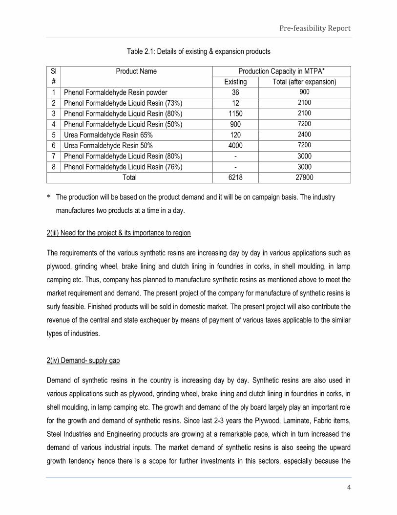
The project site is located at Plot No.64 B and 65 C, KIADB Industrial area, Tubinakere, Mandya Taluk &
District. The plant facilities are spread over 4007 Sq mt (0.99 Acres) in KIADB land. The project site falls in
the Latitude 12029’40.90” N and Longitude 76048’21.81” E at a distance of about 150 mts from the
Bengaluru to Mysore SH 17.
The location details of the project is given below table.
Table 3.1: Location Details
Description Details
Location Plot No. 64B & 65C, KIADB Industrial Area, Tubinakere, Mandya
Taluk & District, Karnataka.
Co-ordinates points Latitude Longitude
A 12029’41.97” N 76048’21.17” E
B 12029’40.17” N 76048’21.40” E
C 12029’42.40” N 76048’23.29” E
D 12029’40.55” N 76048’23.69” E
Village & Plot No. Plot No. 64 B & 65 C, KIADB Industrial Area, Tubinakere,
Mandya Taluk & District, Karnataka.
Total Area 4007 Sq mt ( 0.99 Acres)
Across road Bengaluru to Mysore SH 17 – 150 Mts towards N

Pre-feasibility Report
7
District Headquarters Mandya District Headquarters – 10.6 Kms towards NE
Nearest Town Mandya District- 10.6 Kms towards NE
Nearest Railway Station Mandya Railway Station- 10.6 Kms towards NE
Nearest Airport Mysore Airport- 33.5Kms towards SW
Figure 3.1: Location of project site on Google Map- 5Km radius

Pre-feasibility Report
8
Figure 3.2: Location of the proposed plant on the district map
SITE PHOTOS
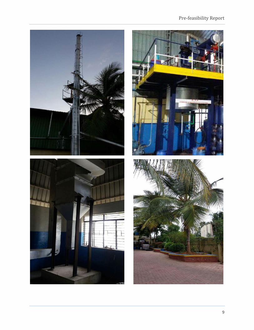
Pre-feasibility Report
9
Pre-feasibility Report
10
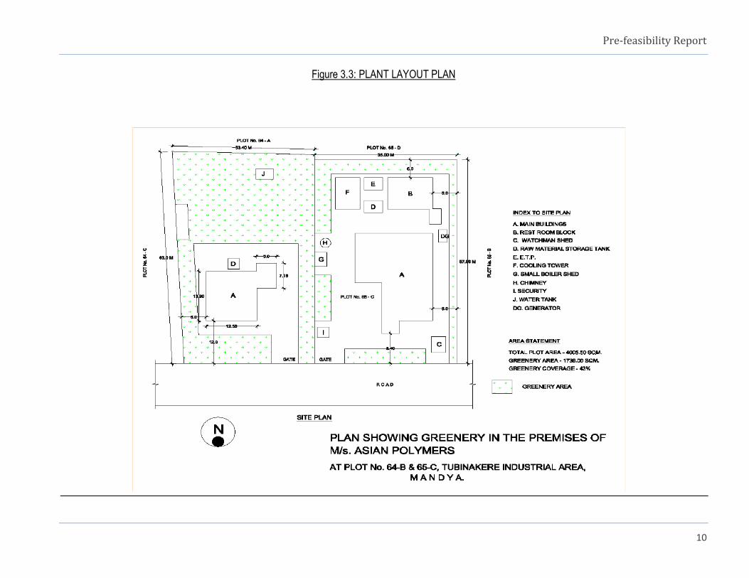
Figure 3.3: PLANT LAYOUT PLAN

Pre-feasibility Report
11
3(iii) Details of alternate sites considered and the basis of selecting the proposed site, particularly the
environmental considerations gone into.
No alternative site is considered as the proposed expansion activity is within the existing premises. The
existing infrastructure (Plant machinery, factory building, office, stores/cold room, security shed, toilet etc.,)
are in the existing facility. Only one new reactor/kettle will be installed adjacent to the existing one within
the process area.
3(iv) Size or magnitude of operation
The list of existing, proposed and expansion product are given in below said table;
Table 3.2: Details of existing, proposed & Expansion products and capacity
Sl
#
Product Name Production Capacity in MTPA*
Existing Total (after expansion)
1 Phenol Formaldehyde Resin powder 36 900
2 Phenol Formaldehyde Liquid Resin (73%) 12 2100
3 Phenol Formaldehyde Liquid Resin (80%) 1150 2100
4 Phenol Formaldehyde Liquid Resin (50%) 900 7200
5 Urea Formaldehyde Resin 65% 120 2400
6 Urea Formaldehyde Resin 50% 4000 7200
7 Phenol Formaldehyde Liquid Resin (80%) - 3000
8 Phenol Formaldehyde Liquid Resin (76%) - 3000
Total 6218 27900
* The production will be based on the product demand and it will be on campaign basis. The industry
manufactures two products at a time in a day.
3(v) Project description with process details (a schematic diagram/flow chart showing the project layout,
components of the project etc.)
Out of eight products two products will be manufactured in a day, as there is only one reactor/kettle. Now
the company is going to put up one additional reactor/kettle for proposed expansion. The product will be
manufactured based on the market/customer’s requirement on campaign basis.

Pre-feasibility Report
12
Process Description:
The manufacturing process details for each products are explained below.
1. PHENOL FORMALDEHYDE RESIN POWDER:
Process in brief:
1. Phenol + Formaldehyde + Para formaldehyde and oxalic acid is charged in the reaction kettle and
reaction carried out under reflex till the reaction is complete.
2. It is then dehydrated and discharged in to M.S trays.
3. The lumps are broken and packed in bags.
4. The batch time is 24 hours.
Reaction chemistry:
Phenol + + + + H2O
Para formaldehyde water
Phenol Formaldehyde Resin Powder

Pre-feasibility Report
13
Process Description (per Day):
INPUT REACTION OUTPUT
Phenol 100% + Formaldehyde 37% +
Para formaldehyde + Oxalic acid + water.
Charged to kettle 4545 Kg reaction mixture
The reaction mixture heating through
indirect steam.
Refluxed till reaction
completed.
4545 Kg refluxed reaction mixture.
The refluxed reaction mixture is vacuum
distilled.
Dehydration. 3000 Kg Phenol Formaldehyde
Resin Powder. Water from
dehydration 1455 kg.
Pre-feasibility Report
14
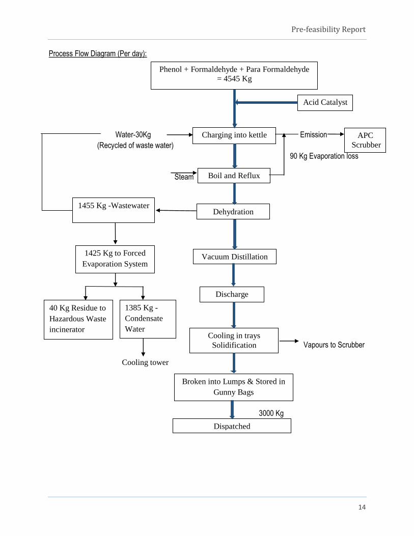
Process Flow Diagram (Per day):
Water-30Kg Emission
(Recycled of waste water)
90 Kg Evaporation loss
Steam
Vapours to Scrubber
Cooling tower
3000 Kg
Phenol + Formaldehyde + Para Formaldehyde
= 4545 Kg
Charging into kettle
Boil and Reflux
Dehydration
Vacuum Distillation
Discharge
Cooling in trays
Solidification
Broken into Lumps & Stored in
Gunny Bags
Dispatched
Acid Catalyst
1455 Kg -Wastewater
1425 Kg to Forced
Evaporation System
1385 Kg -
Condensate
Water
40 Kg Residue to
Hazardous Waste
incinerator
APC
Scrubber

Pre-feasibility Report
15
2. PHENOL FORMALDEHYDE RESIN LIQUID-73%:
Process in brief:
1. Phenol + Formaldehyde + Para formaldehyde + catalyst caustic soda and water charged in the kettle.
2. It is then heated by steam and refluxed.
3. Vacuum distilled will be started.
4. Water will be removed from the vessel as per batch size.
5. Cooling down to 300C.
6. The batch time is 12 hours.
Reaction chemistry
Phenol + + + NaOH + H2O
Para formaldehyde caustic soda water
Phenol Formaldehyde Resin Liquid

Pre-feasibility Report
16
Process Description (per Day):
NPUT REACTION OUTPUT
Phenol 100% + Formaldehyde 37% +
Para formaldehyde + Caustic soda + water
Charged to
kettle
4224.5 Kg reaction mixture
The reaction mixture heating through
indirect steam.
Refluxed till
reaction mixture.
4224.5 Kg refluxed reaction mixture.
The refluxed reaction mixture is vacuum
distilled
Dehydration. 3500 Kg of 73% of Phenol
Formaldehyde Resin Liquid. Water
from dehydration 724.5 kg.
Pre-feasibility Report
17
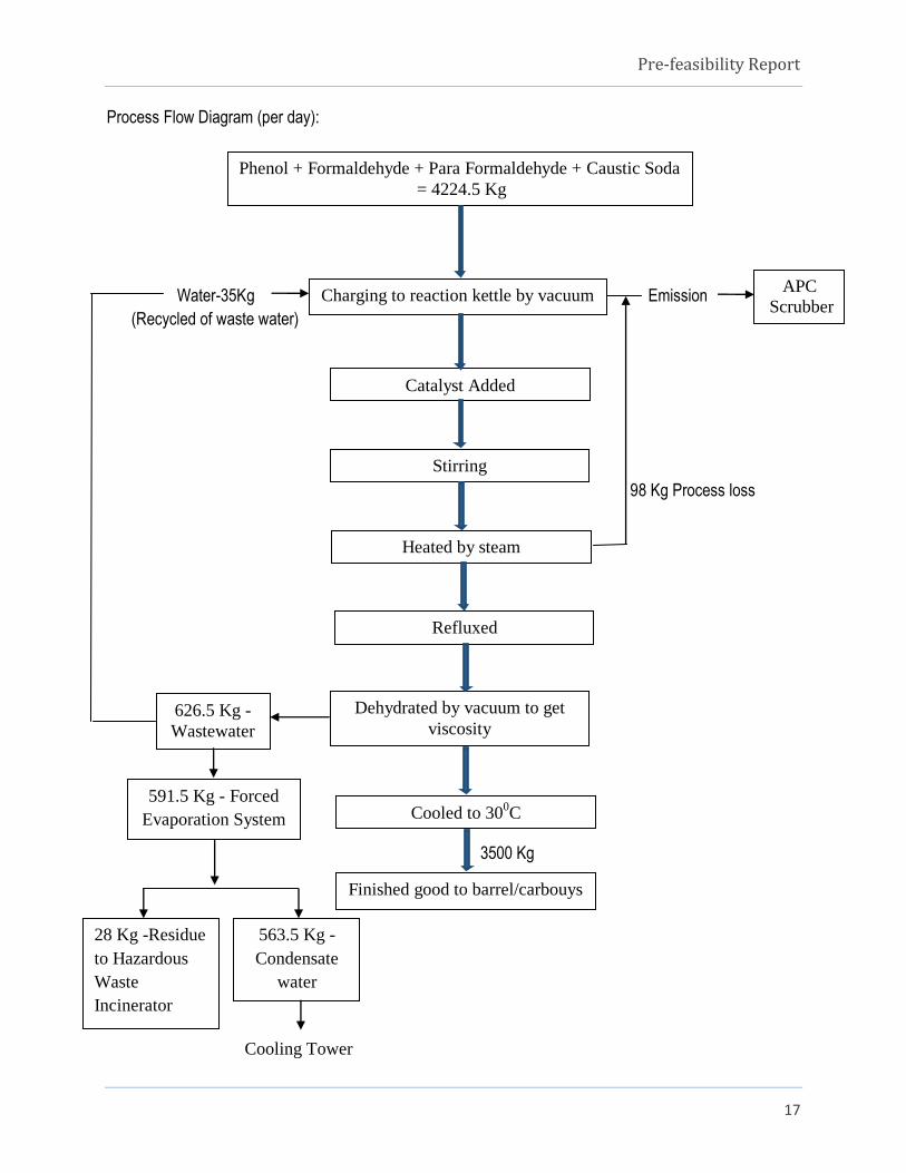
Process Flow Diagram (per day):
Water-35Kg Emission
(Recycled of waste water)
98 Kg Process loss
3500 Kg
Cooling Tower
Charging to reaction kettle by vacuum
Catalyst Added
Stirring
Heated by steam
Refluxed
Dehydrated by vacuum to get
viscosity
Cooled to 300C
Finished good to barrel/carbouys
626.5 Kg -
Wastewater
591.5 Kg - Forced
Evaporation System
563.5 Kg -
Condensate
water
28 Kg -Residue
to Hazardous
Waste
Incinerator
APC
Scrubber
Phenol + Formaldehyde + Para Formaldehyde + Caustic Soda
= 4224.5 Kg
Pre-feasibility Report
18
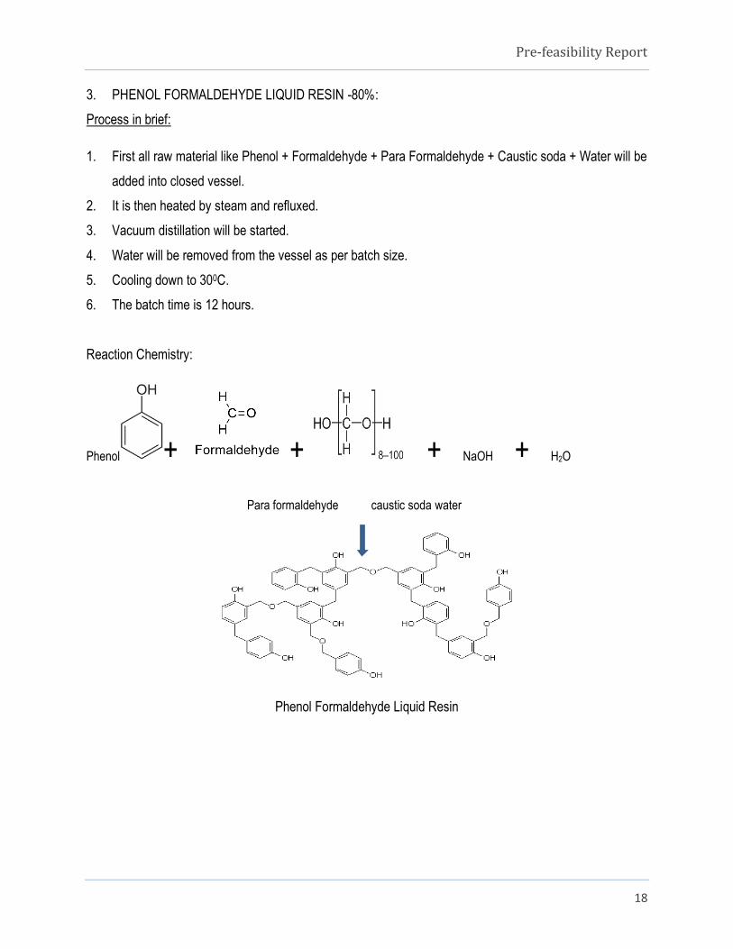
3. PHENOL FORMALDEHYDE LIQUID RESIN -80%:
Process in brief:
1. First all raw material like Phenol + Formaldehyde + Para Formaldehyde + Caustic soda + Water will be
added into closed vessel.
2. It is then heated by steam and refluxed.
3. Vacuum distillation will be started.
4. Water will be removed from the vessel as per batch size.
5. Cooling down to 300C.
6. The batch time is 12 hours.
Reaction Chemistry:
Phenol + + + NaOH + H2O
Para formaldehyde caustic soda water
Phenol Formaldehyde Liquid Resin

Pre-feasibility Report
19
Process Description (per Day):
INPUT REACTION OUTPUT
Phenol 100% + Formaldehyde
37% + Para Formaldehyde +
Caustic Soda + Water
Charged to kettle 5075 Kg reaction mixture
The reaction mixture heating
through indirect steam.
Refluxed till reaction
completed.
5075Kg refluxed reaction mixture.
5075Kg refluxed mixture is
vacuum distilled.
Dehydration is done to get
viscosity and solid content.
3500 Kg 70-80% Phenol
Formaldehyde Liquid Resin. Water
from dehydration 1473.5 Kg.

Pre-feasibility Report
20
Process Flow Diagram (per day):
Water-35Kg Emission
(Recycled of waste water)
101.5 Kg process
loss
3500 Kg
Cooling tower
Charging to reaction kettle by vacuum
Catalyst Added
Stirring
Heated by steam
Refluxed
Dehydrated by vacuum to get
viscosity
Cooled to 300C
Finished good to barrel/carbouys
1473.5 Kg -
Wastewater
1438.5 Kg - Forced
Evaporation System
1398.5 Kg
Condensate
water
40 Kg - Residue
to Hazardous
Waste
Incinerator
APC
Scrubber
Phenol + Formaldehyde + Para Formaldehyde + Caustic Soda
= 5075 Kg

Pre-feasibility Report
21
4. PHENOL FORMALDEHYDE LIQUID RESIN-50%:
Process in brief:
1. First all raw materials viz., Phenol + Formaldehyde + Caustic soda + Water will be added into closed
vessel.
2. It is then heated by steam and refluxed.
3. Vacuum distillation will be started.
4. Cooling down to 300C.
5. The batch time is 6 hours.
Reaction Chemistry:
Phenol + + NaOH + H2O
Caustic soda water
Phenol formaldehyde Liquid Resin
Pre-feasibility Report
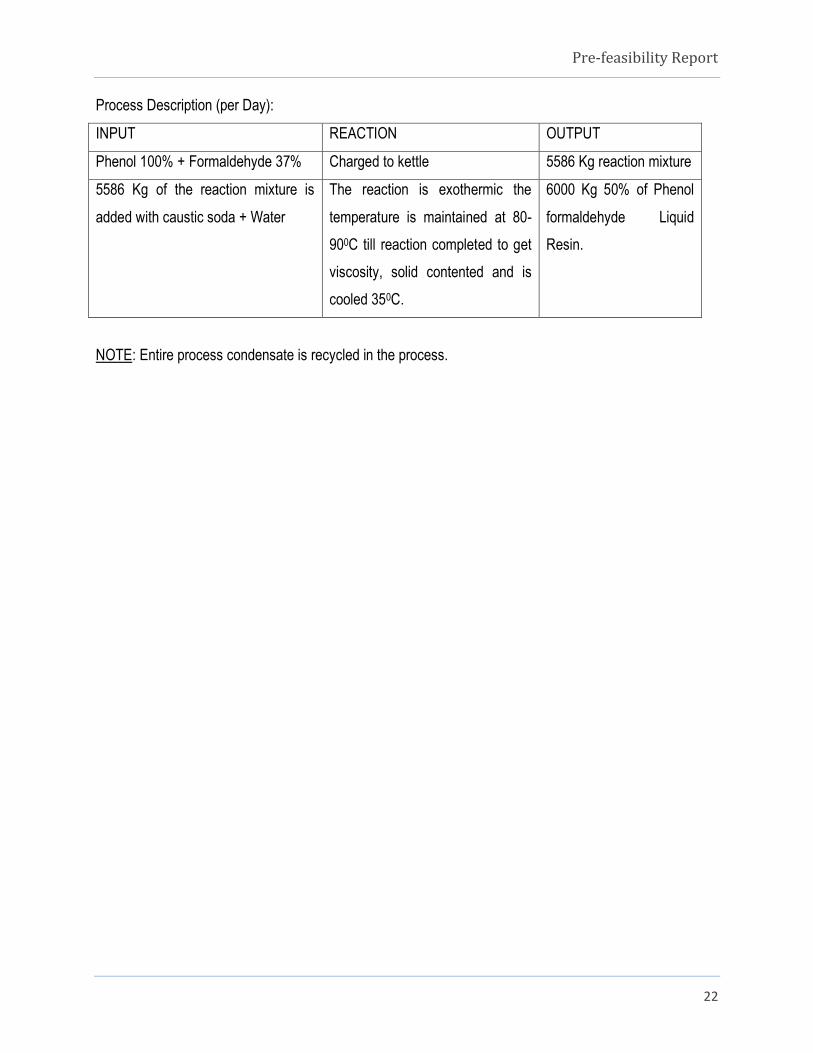
22
Process Description (per Day):
INPUT REACTION OUTPUT
Phenol 100% + Formaldehyde 37% Charged to kettle 5586 Kg reaction mixture
5586 Kg of the reaction mixture is
added with caustic soda + Water
The reaction is exothermic the
temperature is maintained at 80-
900C till reaction completed to get
viscosity, solid contented and is
cooled 350C.
6000 Kg 50% of Phenol
formaldehyde Liquid
Resin.
NOTE: Entire process condensate is recycled in the process.
Pre-feasibility Report
23
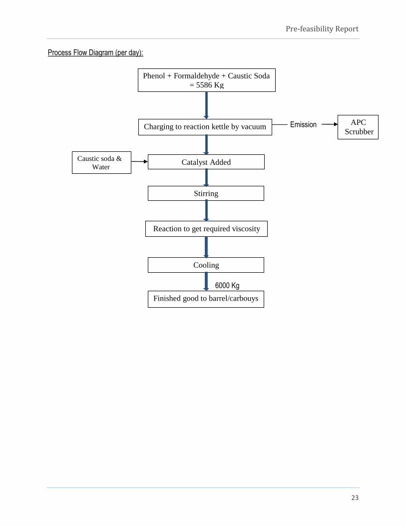
Process Flow Diagram (per day):
Emission
6000 Kg
Charging to reaction kettle by vacuum
Catalyst Added
Stirring
Reaction to get required viscosity
Cooling
Finished good to barrel/carbouys
APC
Scrubber
Phenol + Formaldehyde + Caustic Soda
= 5586 Kg
Caustic soda &
Water

Pre-feasibility Report
24
5. UREA FORMALDEHYDE RESIN LIQUID - 65%:
Process in brief:
1. First all raw materials like Urea + Formaldehyde + Para formaldehyde charged into the kettle.
2. To dissolve everything catalyst caustic soda solution is added to get pH 8.
3. Stirring and heating will done.
4. Dehydrate with steam heating remove water.
5. The citric acid solution is added to get pH 5.5-6.
6. The batch at 800C – 900C to get the required viscosity and pH 8- 8.5.
7. Then cooled till 350C.
8. The batch time is 12 hrs.
Reaction Chemistry:
+ HCHO + + NaOH + H2O
Urea formaldehyde Para formaldehyde caustic soda water
Urea Formaldehyde Liquid Resin 65%.

Pre-feasibility Report
25
Process Description (per Day):
INPUT REACTION OUTPUT
Urea + Formaldehyde 37% + Para
formaldehyde + Caustic soda + water
Charged to kettle 4636 Kg reaction mixture
4636Kg reaction mixture heating
through indirect steam.
Heated to 900C with steam
and dehydrated.
3992 Kg dehydrated mixture
and 564 Kg wastewater.
3992 Kg of dehydrated mixture is
acidified with citric acid solution and pH
is adjusted with caustic soda solution.
Keep at temperature 800C –
900C to get the required
viscosity and solid content
and cooled to 350C.
4000Kg of Urea Formaldehyde
Liquid Resin 65%.
Pre-feasibility Report
26
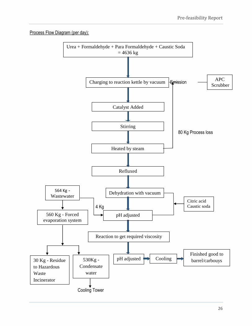
Process Flow Diagram (per day):
Emission
80 Kg Process loss
4 Kg
Cooling Tower
Charging to reaction kettle by vacuum
Catalyst Added
Stirring
Heated by steam
Refluxed
Dehydration with vacuum
Cooling Finished good to
barrel/carbouys
APC
Scrubber
Urea + Formaldehyde + Para Formaldehyde + Caustic Soda
= 4636 kg
pH adjusted
Reaction to get required viscosity
pH adjusted
564 Kg -
Wastewater
560 Kg - Forced
evaporation system
530Kg -
Condensate
water
30 Kg - Residue
to Hazardous
Waste
Incinerator
Citric acid
Caustic soda

Pre-feasibility Report
27
6. UREA FORMALDEHYDE RESIN- 50%:
Process in brief:
1. First all raw materials like Urea + Formaldehyde + Caustic soda and water is charged in to the reactor.
2. Stirring and heating will done.
3. Refluxed at 900C till the reaction is completed.
4. Then cooled till 350C.
5. No effluent is generated in this method.
6. The batch time is 6hrs.
Reaction Chemistry:
+ HCHO + NaOH + H2O
Urea formaldehyde caustic soda water
Citric acid H2O
NaCl
Urea Formaldehyde Liquid Resin 50%.

Pre-feasibility Report
28
Process Description (per Day):
INPUT REACTION OUTPUT
Urea + Formaldehyde 37% +
Caustic Soda + water
Charged to kettle 4196 Kg reaction mixture
The reaction mixture heating
through indirect steam.
Heated to 900C with steam and
refluxed till the reaction is
completed.
4094 Kg of refluxed reaction
mixture & 17Kg evaporation
loss.
4094Kg of refluxed reaction mixture
is acidified with citric acid + sodium
chloride salt+ water + pH is then
adjusted with caustic soda.
Keep at temperature 80 -900C to
get the required viscosity and
solid content. Then cool the
mixture to 350C.
6000 Kg Urea Formaldehyde
Liquid Resin 50%.
NOTE: The entire condensate water from the process is recycled.

Pre-feasibility Report
29
Process Flow Diagram (per day):
Emission
Charging to reaction kettle by vacuum
Catalyst Added
Stirring
Heated by steam
Refluxed
Cooling Finished good to
barrel/carbouys
APC
Scrubber
Urea + Formaldehyde + Caustic Soda
= 4196 Kg
pH adjusted
Reaction to get required viscosity
pH adjusted

Pre-feasibility Report
30
ADDITIONAL PRODUCTS:
7. PHENOL PARA-FORMALDEHYDE LIQUID RESIN-80%:
Process in brief:
1. Phenol + Formaldehyde + Para formaldehyde were charged to reactor and caustic soda was added in
15 intervals for a period of 2 hours.
2. The content will be refluxed in the mean while.
3. The water formed in the reaction was vacuum distilled to get semi solid product.
4. After the contents of the reactor attain the temperature of 300C.
5. Rescorcinol was added and stirred for an hour.
6. Product formed was cooled and tested for quality.
7. The batch time is 12hrs.
Reaction Chemistry:
Phenol +HCHO+ +NaOH ………STEP I
Formaldehyde Para formaldehyde caustic soda
Reaction Mixture 1
+H2O ………… STEP 2
Resorcinol water Reaction mixture 2
Reaction Mixture 1+ Reaction Mixture 2
Pre-feasibility Report
31
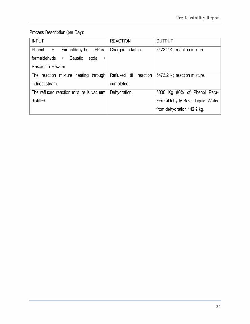
Process Description (per Day):
INPUT REACTION OUTPUT
Phenol + Formaldehyde +Para
formaldehyde + Caustic soda +
Resorcinol + water
Charged to kettle 5473.2 Kg reaction mixture
The reaction mixture heating through
indirect steam.
Refluxed till reaction
completed.
5473.2 Kg reaction mixture.
The refluxed reaction mixture is vacuum
distilled
Dehydration. 5000 Kg 80% of Phenol Para-
Formaldehyde Resin Liquid. Water
from dehydration 442.2 kg.
Pre-feasibility Report
32
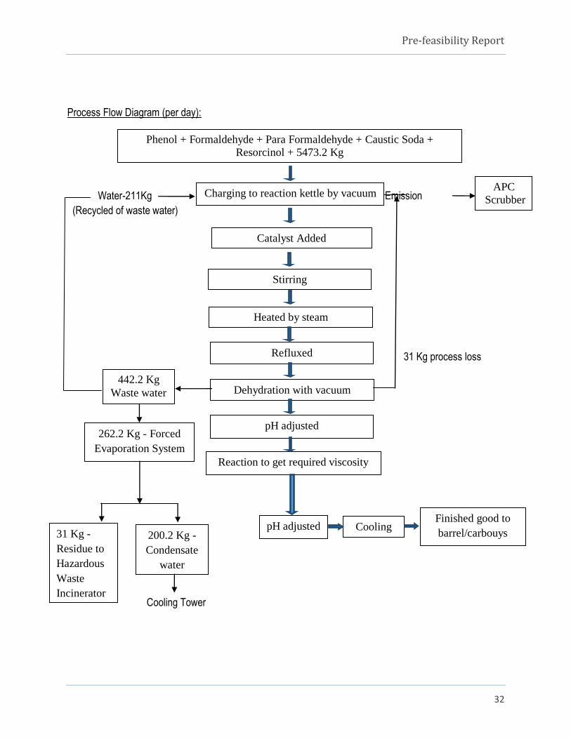
Process Flow Diagram (per day):
Water-211Kg Emission
(Recycled of waste water)
31 Kg process loss
Cooling Tower
Charging to reaction kettle by vacuum
Catalyst Added
Stirring
Heated by steam
Refluxed
Dehydration with vacuum
Cooling Finished good to
barrel/carbouys
APC
Scrubber
Phenol + Formaldehyde + Para Formaldehyde + Caustic Soda +
Resorcinol + 5473.2 Kg
pH adjusted
Reaction to get required viscosity
pH adjusted
442.2 Kg
Waste water
262.2 Kg - Forced
Evaporation System
200.2 Kg -
Condensate
water
31 Kg -
Residue to
Hazardous
Waste
Incinerator

Pre-feasibility Report
33
8. PHENOL PARA-FORMALDEHYDE LIQUID RESIN-76%:
Process in brief:
1. Phenol + Para formaldehyde + Formaldehyde were charged to reactor and caustic soda was added in
15 intervals for a period of 2Hrs.
2. The content will be refluxed in the mean while.
3. The water formed in the reaction was vacuum distilled to get semi solid product.
4. After contents of the reactor attain the temperature of 300C.
5. Urea and melamine was added and stirred for an hour.
6. Product formed was cooled and tested for quality.
7. The batch time is 12hrs.
Reaction Chemistry:
Phenol +HCHO+ + NaOH ……………STEP I
Formaldehyde Para formaldehyde caustic soda
Reaction Mixture 1
NH2 CONH2+ + H2O ……………. STEP 2
Urea Melamine Water
Reaction Mixture 2
Reaction Mixture 1+ Reaction Mixture 2

Pre-feasibility Report
34
Phenol Para-Formaldehyde Liquid Resin-76%
Process Description (per Day):
INPUT REACTION OUTPUT
Phenol + Formaldehyde + Para
formaldehyde + Caustic soda + urea +
Melamin + water
Charged to kettle 5346 Kg reaction mixture
The reaction mixture heating through
indirect steam.
Refluxed till reaction
completed.
5346 Kg reaction mixture.
The reaction mixture is vacuum distilled. Dehydration. 5000 Kg of 76% Phenol Para-
Formaldehyde Resin Liquid. Water
from dehydration 324 kg.
Pre-feasibility Report
35
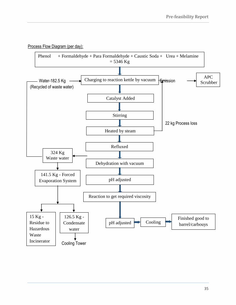
Process Flow Diagram (per day):
Water-182.5 Kg Emission
(Recycled of waste water)
22 kg Process loss
Cooling Tower
Phenol + Formaldehyde + Para Formaldehyde + Caustic Soda + Urea + Melamine
= 5346 Kg
Charging to reaction kettle by vacuum
Catalyst Added
Stirring
Heated by steam
Refluxed
Dehydration with vacuum
Cooling Finished good to
barrel/carbouys
APC
Scrubber
pH adjusted
Reaction to get required viscosity
pH adjusted
324 Kg
Waste water
141.5 Kg - Forced
Evaporation System
126.5 Kg -
Condensate
water
15 Kg -
Residue to
Hazardous
Waste
Incinerator

Pre-feasibility Report
36
Sl.
No.
Product Name Batch
time in
Hours
No. of
Batch/d
ay
Capacity/
batch
Existing
capacity/ann
um in MT
Capacity after
expansion (per
annum in MT) in Kg In MT
1 Phenol Formaldehyde Resin Powder 24 1 3000 3 36 900
2 Phenol Formaldehyde Resin Liquid 73% 12 2 3500 3.5 12 2100
3 Phenol Formaldehyde Liquid Resin 80%. 12 2 3500 3.5 1150 2100
4 Phenol Formaldehyde Liquid Resin 50% 6 4 6000 6 900 7200
5 Urea Formaldehyde Resin 65% 12 2 4000 4 120 2400
6 Urea Formaldehyde Resin 50%. 6 4 6000 6 4000 7200
ADITIONAL PRODUCTS
7 Phenol Para formaldehyde Liquid Resin 80% 12 2 5000 5 - 3000
8 Phenol Paraformaldehyde Liquid Resin 76% 12 2 5000 5 - 3000
Total 6218 27900
NOTE: The above production capacity is arrived considering 300 working days.
3 (vi) Raw material required along with estimated quantity likely source, marketing area of final products,
mode of transport of raw material and finished product:
The raw materials required for all products are given below. The availability of these materials is ever
assured. All raw materials are available in the Indian market. Hence the promoter never expects any
storage in the supply of raw materials.
Table 3.3: Raw Material required for manufacturing of 8 products
Sl No Raw Materials Total required per batch Transportation
Kg/batch T/batch
1 Phenol 12708.5 12.7085 Tankers
2 Formaldehyde 15085.2 15.0852 Tankers
3 Para formaldehyde resin 5437.5 2.4375 Truck
4 Urea 2861.7 2.8617 Truck
5 Caustic soda 358.9 0.3289 Truck
6 Citric acid 10 0.001 Truck
7 Oxalic acid 30 0.003 Truck
8 Sodium Chloride (Salt) 728 0.728 Truck
9 Resorcimol 92.8 0.0928 Truck
10 Melamin 63.5 0.0635 Truck

Pre-feasibility Report
37
3 (vii) Resource optimization/recycling and reuse envisaged in the project, if any, should be briefly outlined.
The wastewater generated from manufacturing process is subjected to evaporation in a Forced Evaporator.
The condensate is collected and recycled back to the process. The concentrate is dried and disposed as
Hazardous Waste.
3 (viii) Availability of water its source, energy/power requirement and source.
Resource requirement:
i. Water Requirement
The source of water for the industry is KIADB Supply- 4750 LPD. Water is used for manufacturing
process, cooling tower, boiler feed, softener regeneration and domestic purpose of about 2050 LPD,
1000 LPD, 1000 LPD, 50 LPD and 700 LPD, respectively.
Table 3.4: Water consumption details
Sl. No. Description Quantity in LPD
1 Domestic 700
2 Process* 2050
3 Softener regeneration plant 50
4 Cooling Tower 1000
5 Boiler feed 1000
Total 4800
*water requirement when two products are manufactured, where the water requirement is maximum.
ii. Energy Requirement
There is no additional power required for proposed expansion activity. The total connected load of the
unit is 100 HP from BESCOM. DG Set will act as a backup facility in case of power failure. The details of
power requirement given in below table;

Pre-feasibility Report
38
Table 3.5: Power & Energy Requirement
Details Capacity
Existing Proposed
Power requirement 100 HP No change
Power backup 62.5 KVA DG Set-1No. No change
Wood husk fired Boiler 1 TPH No change
iii. Manpower Requirement
The Asian polymers is a small scale industry and has employed the local people in the industry. At
present the total manpower is 15 Nos. on direct role which include production manager, supervisor, lab
assistant etc.,
Indirectly many people will be employed as casual laborers, and there is also potential for other
business opportunities such as hired vehicles for the transportation of the finished product etc. It is
estimated that more than 50 people will be benefitted indirectly.
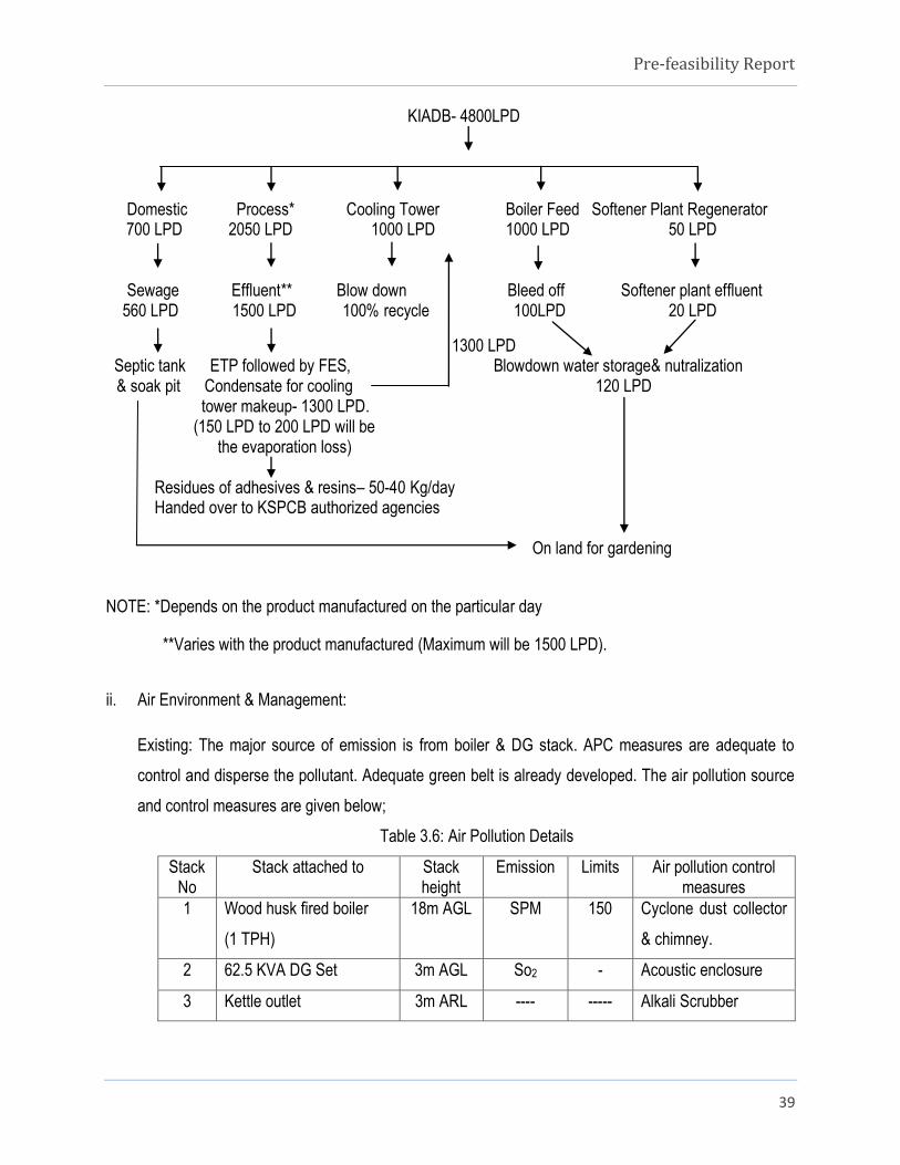
3 (ix) Quantity of wastes to be generated (liquid and solid) and scheme for their management/ disposal.
i. Water Environment & Management:
The wastewater generation per day varies with the type of product manufactured on the particular day.
The quantity of wastewater generation for each product per day considering the number of batches a
day is given in the table below. The cooling tower bleed off is being recycled back, boiler blow down &
softener plant wastewater is being used for gardening. The process effluent is being evaporated in
Forced Evaporation System (FES) of capacity 2000 Ltrs/day. The remaining residues from the FES
which is Hazardous Waste is being disposed to KSPCB Authorized agencies for treatment and
disposal. The sewage is being disposed to septic tank followed by soak pit.
Pre-feasibility Report
39
KIADB- 4800LPD
Domestic Process* Cooling Tower Boiler Feed Softener Plant Regenerator 700 LPD 2050 LPD 1000 LPD 1000 LPD 50 LPD
Sewage Effluent** Blow down Bleed off Softener plant effluent
560 LPD 1500 LPD 100% recycle 100LPD 20 LPD
1300 LPD Septic tank ETP followed by FES, Blowdown water storage& nutralization
& soak pit Condensate for cooling 120 LPD tower makeup- 1300 LPD. (150 LPD to 200 LPD will be the evaporation loss)
Residues of adhesives & resins– 50-40 Kg/day Handed over to KSPCB authorized agencies
On land for gardening
NOTE: *Depends on the product manufactured on the particular day
**Varies with the product manufactured (Maximum will be 1500 LPD).
ii. Air Environment & Management:
Existing: The major source of emission is from boiler & DG stack. APC measures are adequate to
control and disperse the pollutant. Adequate green belt is already developed. The air pollution source
and control measures are given below;
Table 3.6: Air Pollution Details
Stack No
Stack attached to Stack height
Emission Limits Air pollution control measures
1 Wood husk fired boiler
(1 TPH)
18m AGL SPM 150 Cyclone dust collector
& chimney.
2 62.5 KVA DG Set 3m AGL So2 - Acoustic enclosure
3 Kettle outlet 3m ARL ---- ----- Alkali Scrubber
Pre-feasibility Report
40
After Expansion: There is no additional air pollution source for proposed expansion activity. The existing
facility will be enough for additional products and proposed expansion activity.
iii. Solid waste Management:
There is no generation of solid waste from the process, only domestic garbage is the solid waste
generation from the industry. This has being disposed through composting.
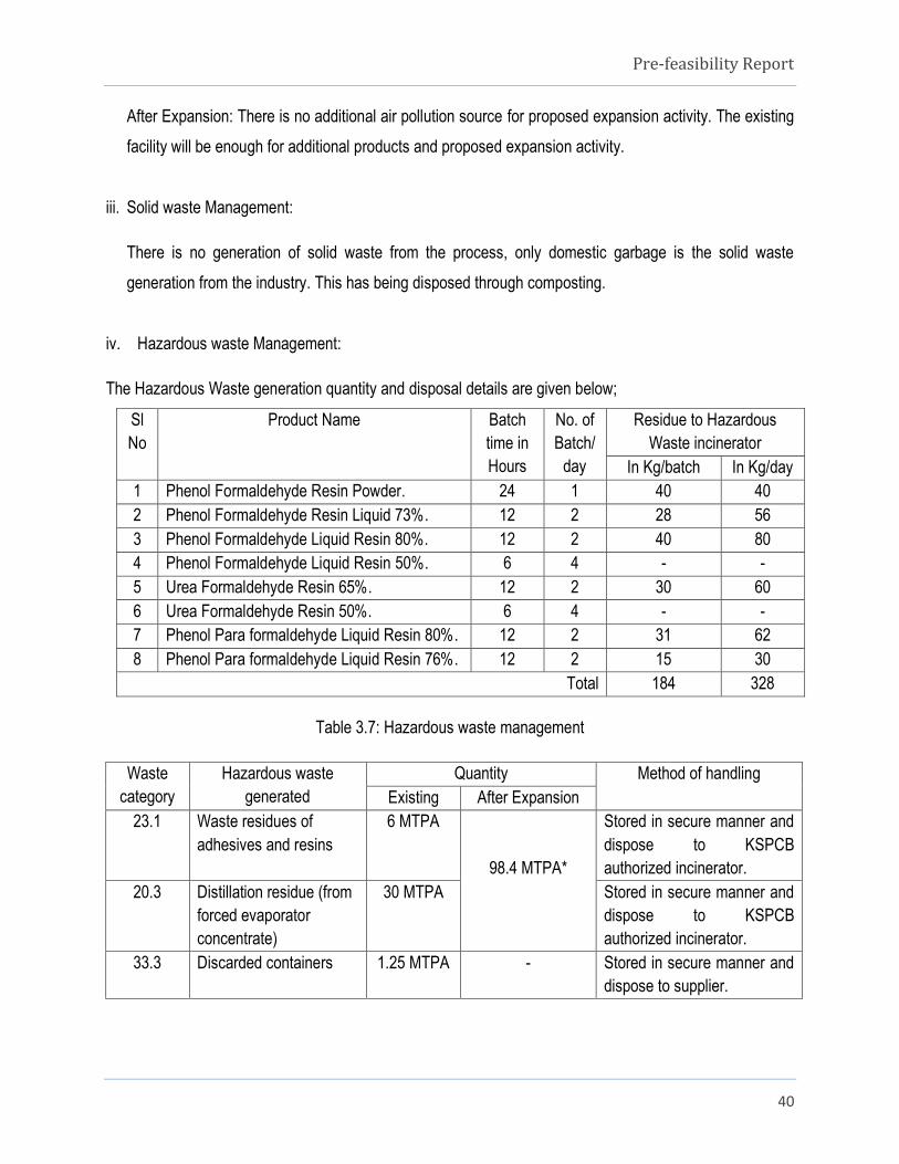
iv. Hazardous waste Management:
The Hazardous Waste generation quantity and disposal details are given below;
Sl
No
Product Name Batch
time in
Hours
No. of
Batch/
day
Residue to Hazardous
Waste incinerator
In Kg/batch In Kg/day
1 Phenol Formaldehyde Resin Powder. 24 1 40 40
2 Phenol Formaldehyde Resin Liquid 73%. 12 2 28 56
3 Phenol Formaldehyde Liquid Resin 80%. 12 2 40 80
4 Phenol Formaldehyde Liquid Resin 50%. 6 4 - -
5 Urea Formaldehyde Resin 65%. 12 2 30 60
6 Urea Formaldehyde Resin 50%. 6 4 - -
7 Phenol Para formaldehyde Liquid Resin 80%. 12 2 31 62
8 Phenol Para formaldehyde Liquid Resin 76%. 12 2 15 30
Total 184 328
Table 3.7: Hazardous waste management
Waste
category
Hazardous waste
generated
Quantity Method of handling
Existing After Expansion
23.1 Waste residues of
adhesives and resins
6 MTPA
98.4 MTPA*
Stored in secure manner and
dispose to KSPCB
authorized incinerator.
20.3 Distillation residue (from
forced evaporator
concentrate)
30 MTPA Stored in secure manner and
dispose to KSPCB
authorized incinerator.
33.3 Discarded containers 1.25 MTPA - Stored in secure manner and
dispose to supplier.

Pre-feasibility Report
41
NOTE: * The quantity calculated is for eight products, however two products will be manufactured at a time
on campaign basis on market demand and the waste residues of adhesives and resins generated from
manufacture of that product will be disposed regularly.
3 (x) Schematic representations of the feasibility drawing which give information of EIA purpose.
Project – Manufacturing of Synthetic Resin
S
Applicability of EIA Notification 2006,
Activity-5(f) “Synthetic Organic Chemicals” in Category “B1” and attracts
MoEF Notification No: Date: S.O. 804(E) 14th
March 2017 (Existing unit
going do expansion and do not have prior EC for the existing operation)
Scoping by EAC
Determine the Terms of Reference
for preparation of EIA
Preparation of EIA as per TOR
Submission to MoEF for
appraisal by EAC
Preparation of Pre-feasibility report
Apply to MoEF along with Form-1
Grant/ Reject of EC
Screening before EAC
Appraisable by EAC
Pre-feasibility Report
42
CHAPTER 4
SITE ANALYSIS
4. SITE ANALYSIS
4(i) CONNECTIVITY
The unit is located at Plot No. 64 B & 65 C, KIADB Industrial Area, Tubinakere, Mandya Taluk & District,
Karnataka State. The unit is well connected by road and rail transportation. The project is located in the
Notified KIADB Industrial Area.
Road Connectivity:
The industry is located off (150 mts on south direction) Bengaluru – Mysore Highway (SH - 17).
Rail connectivity
The nearest railway station is Mandya Railway station which is located at distance of 10.6 Kms in NE
direction from the project site.
Airport connectivity
The nearest Airport is Mysore Airport at approximately 33.5 Kms from the site towards SW direction
from the project site.
Communication
The site has access of telephone, internet and mobile connectivity.
4(ii) LAND FORM, LAND USE AND LAND OWNERSHIP
Land is owned by M/s Asian Polymers. This has been allotted by KIADB in the Industrial Area. The plant
facilities are spread over 4007 Sq mt (0.99 Acres) KIADB Land which is completely fortified and protected
on all four sides by boundary walls. The surrounding area of the project site is Industrial land.
4(iii) TOPOGRAPHY (ALONG WITH MAP)
The site is a flat land and the average elevation is 738 m above MSL. The Latitude and Longitude of project
site is given below table.
Pre-feasibility Report
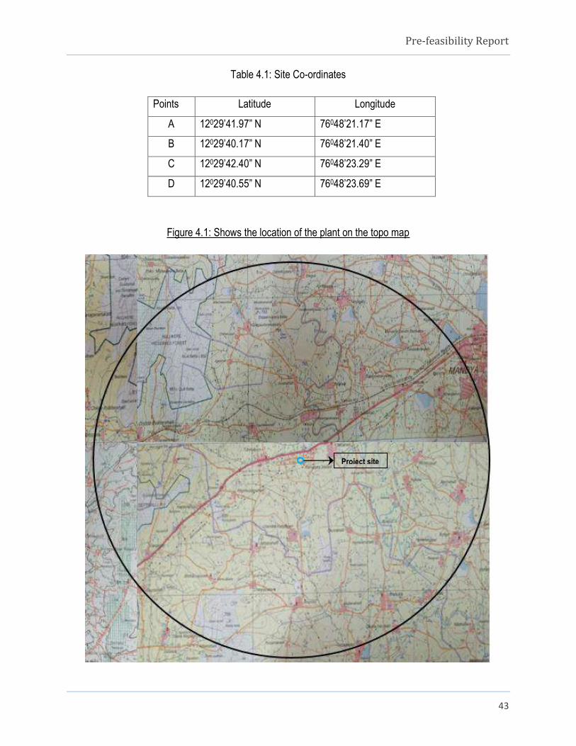
43
Table 4.1: Site Co-ordinates
Points Latitude Longitude
A 12029’41.97” N 76048’21.17” E
B 12029’40.17” N 76048’21.40” E
C 12029’42.40” N 76048’23.29” E
D 12029’40.55” N 76048’23.69” E
Figure 4.1: Shows the location of the plant on the topo map
Project site

Pre-feasibility Report
44
4(iv) Existing Land Use Pattern (Agriculture, Non-Agriculture, Forest, Water Bodies (Including Area Under
CRZ)), Shortest Distance From The Periphery of The Project To Periphery of The Forests, National Park,
Wildlife Sanctuary, Eco Sensitive Areas, Water Bodies (Distance From The HFL of The River), CRZ. In
Case of Notified Industrial Area, a Copy of the Gazette Notification Should be given.
Industry is located in Industrial area developed by KIADB. The existing plot is non-agricultural land and
industrial activity is carried out for manufacturing of synthetic resin. There are no eco sensitive areas such
as Forest, National Park, Wildlife Sanctuary, Biosphere Reserves and Wildlife Corridors etc. located within
15 Kms radius of project area.
4(v) Existing Infrastructure
Total area of the project site is 4007 Sq mt (0.99 Acres), the existing unit has raw material storage facility,
production area, office etc., One No. of new reactor/kettle will be come up for proposed expansion activity
within the existing production area adjacent to existing reactor/kettle.
4(vi) Soil Classification
The soil of Mandya district is derived from granites and gneisses interdependent with occasional patches of
schist. The soils range from red sandy loams to red clay loam very thin in ridges and higher elevations and
comparatively thick in valley portion. The soil in Mandya District is thin gravelly and underlain with a
murrum zone containing weathered rock. The soil is highly leached and poor in bases. The infiltration rate
of red loamy and red soils is 2 to 12 cm/hr and 1 to 3 cm/hr.
4(vii) Climatic data from secondary sources
During the year, there is little rainfall in Mandya. The minimum temperature is about 100C and maximum
temperature is about 39 °C. The rainfall in the year is 957 mm.
The classification of months according to the seasons is given in the following table;
Season Period
Summer March to May
Monsoon June to September
Post monsoon October to November
Winter December to February

Pre-feasibility Report
45
The driest month is January, with no rain fall. Most precipitation falls in September, with a rainfall of 188
mm.
April and May is the warmest month of the year. The maximum temperature will be 99°C. In January, the
minimum temperature is 15°C. It is the lowest average temperature of the whole year.
The annual temperature graph and precipitation graph are given below said table.
Table 4.2: Climatic Data
Month Min. Temperature
(°C)
Max. Temperature
(°C)
Humidity % Precipitation
/Rainfall (mm)
Wind Speed
Km/hr
January 10 33 60 0 5
February 11 37 52 9 5
March 10 38 46 18 4
April 18 39 54 81 4
May 15 38 64 90 6
June 14 38 74 112 10
July 11 37 77 134 10
August 11 38 79 99 8
September 11 33 76 188 5
October 12 33 78 149 4
November 12 33 73 62 5
December 12 32 68 15 5

Pre-feasibility Report
46
Figure 4.2: Annual Temperature Graph of Mandya
Figure 4.3: Annual Precipitation Graph of Mandya
4(viii) Social infrastructure available
Social infrastructure facilities such as schools, hospitals, community halls, markets, collages, railway station
and religious building are located with 10 Km radius from the site.

Pre-feasibility Report
47
CHAPTER-5
PLANNING BRIEF
5. PLANNING BRIEF
5(i) Planning concept:
Asian polymers is located in designated Industrial Area (KIADB, Tubinakere, Mandya). All infrastructure
facilities viz, water, electricity, road, skilled & unskilled manpower etc., are available.
5(ii) Population Projection:
An official Census 2011 detail of Mandya, it had population of 1,805,769 of which male and female were
905,085 and 900,684 respectively.
Table 5.1: Census Data
Description 2011
Actual Population 1,805,769
Male 905,085
Female 900,684
Population Growth 2.38%
Area Sq. Km 4,962
Average Literacy 70.40
Male Literacy 78.27
Female Literacy 62.54
Total Child Population (0-6 Age) 172,685
Male Population (0-6 Age) 89,063
Female Population (0-6 Age) 83,622
Literates 1,149,649
Male Literates 638,668
Female Literates 510,981
Child Proportion (0-6 Age) 9.56%
Boys Proportion (0-6 Age) 9.84%
Girls Proportion (0-6 Age) 9.28%

Pre-feasibility Report
48
5(iii) Land use planning (breakup along with green belt etc)
The plant is located at 64 D & 65 C, KIADB Industrial Area, Tubinakere, Mandya Taluk and District. The
land use pattern is as shown in the table.
Table 5.2: Land Used Planning
Sl. No. Particulars Area (m2) In %
1 Total Plot Area 4007 -
2 Ground coverage area (total built up area) 2404 60
3 Green belt 1603 40
5(iv) Assessment of infrastructure demand (physical & social)
The infrastructure facility is already available which shall be used and properly maintained. Two Nos. of
new reactor/kettle will be installed adjacent to the existing one within the process area.
5(v) Amenities/Facilities
Basic amenities/facilities is available as road, power supply, communication, water supply, medical and
health checkup of workers and staff of the facility will be provided with the necessary Personal Protective
Equipments and periodical medical checkups will be provided to the employees.

Pre-feasibility Report
49
CHAPTER 6
PROPOSED INFRASTRUCTURE
6. PROPOSED INFRASTRUCTURE
6(i) Industrial area (processing area)
The existing infrastructure (Plant machinery, factory building, office, stores/cold room, security shed, toilet
etc.,) are in the existing facility. Only one new reactor/kettle will be installed adjacent to the existing one
within the process area.
6(ii) Residential area (Non- processing area)
No residential area is proposed.
6(iii) Green Belt
Green belt is already developed. Trees and Plants of the various species predominant in the district are
being planted in the peripheral area.
The fruit bearing species such as coconut tree, Pomegranate, Sapota, Neem, Drum Stick, Teak etc., are
planted.
6(iv) Social Infrastructure
Schools, colleges, hospitals & healthcare centers, shops & bazaars, community centers, etc. are all
available in nearby Mandya town. The workers and employees will be residing either at Mandya or
Srirangapattana.
6(v) Connectivity (traffic and transportation/road/rail/metro/water ways etc.)
The unit is located at Plot No. 64 B & 65 C, KIADB Industrial Area, Tubinakere, Mandya Taluk & District,
Karnataka State. The unit is well connected by road and rail mode of transportation. The project is located
in the Notified KIADB Industrial Area.
Road Connectivity:
The industry is located off (150 mts on south direction) Bengaluru – Mysore Highway (SH - 17).
Pre-feasibility Report
50
Rail connectivity:
The nearest railway station is Mandya Railway station which is located at distance of 10.6 Kms in
NE direction from the project site.
Airport connectivity:
The nearest Airport is Mysore Airport at approximately 33.5 Kms from the site towards SW
direction from the project site.
Communication:
The site has access of telephone, internet and mobile connectivity
6(vi) Drinking water management (source and supply of water)
Drinking water will be sourced from the bore well & KIADB supply which is located within industry premises.
6(vii) Sewerage Management.
The domestic sewage is being treated in septic tank and discharged to soak pits.
6(viii) Industrial Waste Management
The trade effluent generated from the process will be evaporated in Forced Evaporation System (FES). The
condensate is recycled back. The boiler blow down and softener plant effluent is used for gardening after
treatment.
6(ix) Solid Waste Management
There is no generation of solid waste from the process, only domestic garbage is the solid waste
generation from the industry. This has being disposed through composting.
6(x) Power requirement & supply/source
Average Power requirement for the unit is 100 HP. The Supply source of power is BESCOM in case of
power failure D.G. Set (62.5 KVA capacity) will be used as back up.

Pre-feasibility Report
51
CHAPTER 7
REHABILITATION & RESETTLEMENT PLAN(R&R)
7. REHABILITATION & RESETTLEMENT PLAN (R&R)
7(i) Policy to adopted (central/state) in respect of the project affected person including home oustees, Land
oustee and landless labour (a brief outline to be given).
Rehabilitation and Resettlement (R & R) Plan is not applicable since the project is in KIADB Industrial Area
Tubinakere, Mandya Taluk & District, Karnataka State.
Pre-feasibility Report
52
CHAPTER 8
PROJECT SCHEDULE & COST ESTIMATES
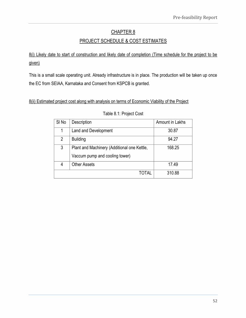
8(i) Likely date to start of construction and likely date of completion (Time schedule for the project to be
given)
This is a small scale operating unit. Already infrastructure is in place. The production will be taken up once
the EC from SEIAA, Karnataka and Consent from KSPCB is granted.
8(ii) Estimated project cost along with analysis on terms of Economic Viability of the Project
Table 8.1: Project Cost
Sl No Description Amount in Lakhs
1 Land and Development 30.87
2 Building 94.27
3 Plant and Machinery (Additional one Kettle,
Vaccum pump and cooling tower)
168.25
4 Other Assets 17.49
TOTAL 310.88
Pre-feasibility Report
53
CHAPTER 9
ANALYSIS OF PROPOSAL (FINAL RECOMMENDATIONS)
9(i) Financial and Social benefits with special emphases on the benefit to the local people including tribal
population, if any, in the area.
Ours is a very small scale operating unit. It is a proprietary concern. The local people around 50 of them will
be directly or indirectly employed and benefited. There is a growing demand for resins in the India and
State in particular. The present project will also contribute to the revenue of the central and state exchequer
by means of payment of various taxes applicable.

Pre-feasibility Report
54
Annexure-1
CFO Compliance
Pre-feasibility Report
55
Annexure-2
Onsite Emergency Plan