Embed Size (px)
Citation preview

PowerPC Virtual Environment Architecture
Book II
Version 2.01
December 2003
Manager:Joe Wetzel/Poughkeepsie/IBM
Technical Content:Ed Silha/Austin/IBM Cathy May/Watson/IBM Brad Frey/Austin/IBM

The following paragraph does not apply to the United Kingdom or any country or state where such provisions areinconsistent with local law.
The specifications in this manual are subject to change without notice. This manual is provided “AS IS”. Interna-tional Business Machines Corp. makes no warranty of any kind, either expressed or implied, including, but notlimited to, the implied warranties of merchantability and fitness for a particular purpose.
International Business Machines Corp. does not warrant that the contents of this publication or the accompanyingsource code examples, whether individually or as one or more groups, will meet your requirements or that thepublication or the accompanying source code examples are error-free.
This publication could include technical inaccuracies or typographical errors. Changes are periodically made tothe information herein; these changes will be incorporated in new editions of the publication.
Address comments to IBM Corporation, Internal Zip 9630, 11400 Burnett Road, Austin, Texas 78758-3493. IBMmay use or distribute whatever information you supply in any way it believes appropriate without incurring anyobligation to you.
The following terms are trademarks of the International Business Machines Corporation in the United Statesand/or other countries:
IBM PowerPC RISC/System 6000 POWER POWER2 POWER4 POWER4+ IBM System/370
Notice to U.S. Government Users—Documentation Related to Restricted Rights—Use, duplication or disclosure issubject to restrictions set fourth in GSA ADP Schedule Contract with IBM Corporation.
Copyright International Business Machines Corporation, 1994, 2003. All rights reserved.
ii PowerPC Virtual Environment Architecture
Version 2.01
Preface
This document defines the additional instructions andfacilities, beyond those of the PowerPC User Instruc-tion Set Architecture, that are provided by thePowerPC Virtual Environment Architecture. It coversthe storage model and related instructions and facili-ties available to the application programmer, and theTime Base as seen by the application programmer.
Other related documents define the PowerPC UserInstruction Set Architecture, the PowerPC OperatingEnvironment Architecture, and PowerPC Implementa-tion Features. Book I, PowerPC User Instruction SetArchitecture defines the base instruction set andrelated facilities available to the application pro-
grammer. Book III, PowerPC Operating EnvironmentArchitecture defines the system (privileged)instructions and related facilities. Book IV, PowerPCImplementation Features defines the implementa-tion-dependent aspects of a particular implementa-tion.
As used in this document, the term “PowerPC Archi-tecture” refers to the instructions and facilitiesdescribed in Books I, II, and III. The description of theinstantiation of the PowerPC Architecture in a givenimplementation includes also the material in Book IVfor that implementation.
Preface iii

Version 2.01
iv PowerPC Virtual Environment Architecture

Version 2.01
Table of Contents
Chapter 1. Storage Model . . . . . . . 11.1 Definitions and Notation . . . . . . . 11.2 Introduction . . . . . . . . . . . . . . 21.3 Virtual Storage . . . . . . . . . . . . 21.4 Single-Copy Atomicity . . . . . . . . 31.5 Cache Model . . . . . . . . . . . . . 31.6 Storage Control Attributes . . . . . 41.6.1 Write Through Required . . . . . 41.6.2 Caching Inhibited . . . . . . . . . . 41.6.3 Memory Coherence Required . . 51.6.4 Guarded . . . . . . . . . . . . . . . 51.7 Shared Storage . . . . . . . . . . . . 61.7.1 Storage Access Ordering . . . . . 61.7.2 Storage Ordering of I/O Accesses 81.7.3 Atomic Update . . . . . . . . . . . 81.8 Instruction Storage . . . . . . . . . . 101.8.1 Concurrent Modification and
Execution of Instructions . . . . . . . . 12
Chapter 2. Effect of OperandPlacement on Performance . . . . . . 13
2.1 Instruction Restart . . . . . . . . . . 14
Chapter 3. Storage ControlInstructions . . . . . . . . . . . . . . . . . . 15
3.1 Parameters Useful to ApplicationPrograms . . . . . . . . . . . . . . . . . 15
3.2 Cache Management Instructions . 163.2.1 Instruction Cache Instruction . . . 173.2.2 Data Cache Instructions . . . . . . 183.3 Synchronization Instructions . . . . 213.3.1 Instruction Synchronize Instruction 213.3.2 Load And Reserve and Store
Conditional Instructions . . . . . . . . . 223.3.3 Memory Barrier Instructions . . . 25
Chapter 4. Time Base . . . . . . . . . . 294.1 Time Base Instructions . . . . . . . 304.2 Reading the Time Base . . . . . . . 30
4.3 Computing Time of Day from theTime Base . . . . . . . . . . . . . . . . 30
Chapter 5. Optional Facilities andInstructions . . . . . . . . . . . . . . . . . . 33
5.1 External Control . . . . . . . . . . . 335.1.1 External Access Instructions . . . 345.2 Storage Control Instructions . . . . 355.2.1 Cache Management Instructions 355.3 Little-Endian . . . . . . . . . . . . . . 36
Appendix A. Assembler ExtendedMnemonics . . . . . . . . . . . . . . . . . . 37
A.1 Synchronize Mnemonics . . . . . . 37
Appendix B. Programming Examplesfor Sharing Storage . . . . . . . . . . . . 39
B.1 Atomic Update Primitives . . . . . 39B.2 Lock Acquisition and Release, and
Related Techniques . . . . . . . . . . . 41B.2.1 Lock Acquisition and Import
Barriers . . . . . . . . . . . . . . . . . . 41B.2.2 Lock Release and Export Barriers 42B.2.3 Safe Fetch . . . . . . . . . . . . . . 42B.3 List Insertion . . . . . . . . . . . . . 43B.4 Notes . . . . . . . . . . . . . . . . . . 43
Appendix C. Cross-Reference forChanged POWER Mnemonics . . . . 45
Appendix D. New Instructions . . . . . 47
Appendix E. PowerPC VirtualEnvironment Instruction Set . . . . . . 49
Index . . . . . . . . . . . . . . . . . . . . . . . 51
Last Page - End of Document . . . . . 53
Table of Contents v
Version 2.01
vi PowerPC Virtual Environment Architecture

Version 2.01
Figures
1. Performance effects of storage operandplacement . . . . . . . . . . . . . . . . . . 13
2. Time Base . . . . . . . . . . . . . . . . . . 293. Performance effects of storage operand
placement, Little-Endian mode . . . . . . . 36
Figures vii

Version 2.01
viii PowerPC Virtual Environment Architecture

Version 2.01
Chapter 1. Storage Model
1.1 Definitions and Notation . . . . . . . 11.2 Introduction . . . . . . . . . . . . . . 21.3 Virtual Storage . . . . . . . . . . . . 21.4 Single-Copy Atomicity . . . . . . . . 31.5 Cache Model . . . . . . . . . . . . . 31.6 Storage Control Attributes . . . . . 41.6.1 Write Through Required . . . . . 41.6.2 Caching Inhibited . . . . . . . . . . 41.6.3 Memory Coherence Required . . 51.6.4 Guarded . . . . . . . . . . . . . . . 5
1.7 Shared Storage . . . . . . . . . . . . 61.7.1 Storage Access Ordering . . . . . 61.7.2 Storage Ordering of I/O Accesses 81.7.3 Atomic Update . . . . . . . . . . . 81.7.3.1 Reservations . . . . . . . . . . . 81.7.3.2 Forward Progress . . . . . . . . 101.8 Instruction Storage . . . . . . . . . . 101.8.1 Concurrent Modification and
Execution of Instructions . . . . . . . . 12
1.1 Definitions and Notation
The following definitions, in addition to those specifiedin Book I, are used in this Book. In these definitions,“ Load instruction” includes the Cache Managementand other instructions that are stated in the instruc-tion descriptions to be “treated as a Load” , and simi-larly for “ Store instruction”.
■ processorA hardware component that executes theinstructions specified in a program.
■ systemA combination of processors, storage, and associ-ated mechanisms that is capable of executingprograms. Sometimes the reference to systemincludes services provided by the operatingsystem.
■ main storageThe level of the storage hierarchy in which allstorage state is visible to all processors andmechanisms in the system.
■ instruction storageThe view of storage as seen by the mechanismthat fetches instructions.
■ data storageThe view of storage as seen by a Load or Storeinstruction.
■ program orderThe execution of instructions in the orderrequired by the sequential execution model. (Seethe section entitled “Instruction Execution Order”in Book I. A dcbz instruction that modifies
storage which contains instructions has the sameeffect with respect to the sequential executionmodel as a Store instruction as described there.)
■ storage locationA contiguous sequence of bytes in storage. Whenused in association with a specific instruction orthe instruction fetching mechanism, the length ofthe sequence of bytes is typically implied by theoperation. In other uses, it may refer moreabstractly to a group of bytes which sharecommon storage attributes.
■ storage accessAn access to a storage location. There are three(mutually exclusive) kinds of storage access.— data access
An access to the storage location specifiedby a Load or Store instruction, or, if theaccess is performed “out-of-order” (see BookIII), an access to a storage location as if itwere the storage location specified by a Loador Store instruction.
— instruction fetchAn access for the purpose of fetching aninstruction.
— implicit accessAn access by the processor for the purposeof address translation or reference andchange recording (see Book III).
■ caused by, associated with— caused by
A storage access is said to be caused by aninstruction if the instruction is a Load orStore and the access (data access) is to thestorage location specified by the instruction.
Chapter 1. Storage Model 1

Version 2.01
— associated withA storage access is said to be associatedwith an instruction if the access is for thepurpose of fetching the instruction (instruc-tion fetch), or is a data access caused by theinstruction, or is an implicit access thatoccurs as a side effect of fetching or exe-cuting the instruction.
■ prefetched instructionsInstructions for which a copy of the instructionhas been fetched from instruction storage, but theinstruction has not yet been executed.
■ uniprocessorA system that contains one processor.
■ multiprocessorA system that contains two or more processors.
■ shared storage multiprocessorA multiprocessor that contains some commonstorage, which all the processors in the systemcan access.
■ performedA load or instruction fetch by a processor ormechanism (P1) is performed with respect to anyprocessor or mechanism (P2) when the value tobe returned by the load or instruction fetch canno longer be changed by a store by P2. A storeby P1 is performed with respect to P2 when aload by P2 from the location accessed by thestore will return the value stored (or a valuestored subsequently). An instruction cache blockinvalidation by P1 is performed with respect to P2when an instruction fetch by P2 will not be satis-fied from the copy of the block that existed in itsinstruction cache when the instruction causing theinvalidation was executed, and similarly for adata cache block invalidation. The precedingdefinitions apply regardless of whether P1 and P2are the same entity.
■ pageAn aligned unit of storage for which protectionand control attributes are independentlyspecifiable and for which reference and changestatus are independently recorded. Two virtualpage sizes are supported simultaneously, 4 KBand a larger size. The larger size is an imple-mentation-dependent power of 2 (bytes). Realpages are always 4 KB.
■ blockThe aligned unit of storage operated on by eachCache Management instruction. The size of ablock can vary by instruction and by implementa-tion. The maximum block size is 4 KB.
■ aligned storage accessA load or store is aligned if the address of thetarget storage location is a multiple of the size ofthe transfer effected by the instruction.
1.2 Introduction
The PowerPC User Instruction Set Architecture, dis-cussed in Book I, defines storage as a linear array ofbytes indexed from 0 to a maximum of 264 − 1. Eachbyte is identified by its index, called its address, andeach byte contains a value. This information is suffi-cient to allow the programming of applications thatrequire no special features of any particular systemenvironment. The PowerPC Virtual EnvironmentArchitecture, described herein, expands this simplestorage model to include caches, virtual storage, andshared storage multiprocessors. The PowerPC VirtualEnvironment Architecture, in conjunction with servicesbased on the PowerPC Operating Environment Archi-tecture (see Book III) and provided by the operatingsystem, permits explicit control of this expandedstorage model. A simple model for sequential exe-cution allows at most one storage access to be per-formed at a time and requires that all storageaccesses appear to be performed in program order.In contrast to this simple model, the PowerPC Archi-tecture specifies a relaxed model of storage consist-ency. In a multiprocessor system that allows multiplecopies of a storage location, aggressive implementa-tions of the architecture can permit intervals of timeduring which different copies of a storage locationhave different values. This chapter describes fea-tures of the PowerPC Architecture that enable pro-grammers to write correct programs for this storagemodel.
1.3 Virtual Storage
The PowerPC system implements a virtual storagemodel for applications. This means that a combina-tion of hardware and software can present a storagemodel that allows applications to exist within a“virtual” address space larger than either the effec-tive address space or the real address space.
Each program can access 264 bytes of “effectiveaddress” (EA) space, subject to limitations imposedby the operating system. In a typical PowerPCsystem, each program's EA space is a subset of alarger “virtual address” (VA) space managed by theoperating system.
Each effective address is translated to a real address(i.e., to an address of a byte in real storage or on anI/O device) before being used to access storage. Thehardware accomplishes this, using the address trans-lation mechanism described in Book III. The oper-ating system manages the real (physical) storageresources of the system, by setting up the tables andother information used by the hardware addresstranslation mechanism.
2 PowerPC Virtual Environment Architecture

Version 2.01
Book II deals primarily with effective addresses thatare in “segments” translated by the “address trans-lation mechanism” (see Book III). Each such effectiveaddress lies in a “virtual page”, which is mapped to a“real page” (4 KB virtual page) or to a contiguoussequence of real pages (large virtual page) beforedata or instructions in the virtual page are accessed.
In general, real storage may not be large enough tomap all the virtual pages used by the currently activeapplications. With support provided by hardware, theoperating system can attempt to use the availablereal pages to map a sufficient set of virtual pages ofthe applications. If a sufficient set is maintained,“paging” activity is minimized. If not, performancedegradation is likely.
The operating system can support restricted access tovirtual pages (including read/write, read only, and noaccess; see Book III), based on system standards(e.g., program code might be read only) and applica-tion requests.
1.4 Single-Copy Atomicity
An access is single-copy atomic, or simply atomic, if itis always performed in its entirety with no visiblefragmentation. Atomic accesses are thus serialized:each happens in its entirety in some order, evenwhen that order is not specified in the program orenforced between processors.
In PowerPC the following single-register accesses arealways atomic:
■ byte accesses (all bytes are aligned on byteboundaries)
■ halfword accesses aligned on halfword bounda-ries
■ word accesses aligned on word boundaries
■ doubleword accesses aligned on doublewordboundaries
No other accesses are guaranteed to be atomic. Forexample, the access caused by the followinginstructions is not guaranteed to be atomic.
■ any Load or Store instruction for which theoperand is unaligned
■ lmw, stmw, lswi, lswx, stswi, stswx■ any Cache Management instruction
An access that is not atomic is performed as a set ofsmaller disjoint atomic accesses. The number andalignment of these accesses are implementa-tion-dependent, as is the relative order in which theyare performed.
The results for several combinations of loads andstores to the same or overlapping locations aredescribed below.
1. When two processors execute atomic stores tolocations that do not overlap, and no other storesare performed to those locations, the contents ofthose locations are the same as if the two storeswere performed by a single processor.
2. When two processors execute atomic stores tothe same storage location, and no other store isperformed to that location, the contents of thatlocation are the result stored by one of theprocessors.
3. When two processors execute stores that havethe same target location and are not guaranteedto be atomic, and no other store is performed tothat location, the result is some combination ofthe bytes stored by both processors.
4. When two processors execute stores to overlap-ping locations, and no other store is performed tothose locations, the result is some combination ofthe bytes stored by the processors to the over-lapping bytes. The portions of the locations thatdo not overlap contain the bytes stored by theprocessor storing to the location.
5. When a processor executes an atomic store to alocation, a second processor executes an atomicload from that location, and no other store is per-formed to that location, the value returned by theload is the contents of the location before thestore or the contents of the location after thestore.
6. When a load and a store with the same targetlocation can be executed simultaneously, and noother store is performed to that location, thevalue returned by the load is some combinationof the contents of the location before the storeand the contents of the location after the store.
1.5 Cache Model
A cache model in which there is one cache forinstructions and another cache for data is called a“Harvard-style” cache. This is the model assumed bythe PowerPC Architecture, e.g., in the descriptions ofthe Cache Management instructions in Section 3.2,“Cache Management Instructions” on page 16. Alter-native cache models may be implemented (e.g., a“combined cache” model, in which a single cache isused for both instructions and data, or a model inwhich there are several levels of caches), but theysupport the programming model implied by aHarvard-style cache.
The processor is not required to maintain copies ofstorage locations in the instruction cache consistentwith modifications to those storage locations (e.g.,modifications caused by Store instructions).
Chapter 1. Storage Model 3

Version 2.01
A location in the data cache is considered to be modi-fied in that cache if the location has been modified(e.g., by a Store instruction) and the modified datahave not been been written to main storage.
Cache Management instructions are provided so thatprograms can manage the caches when needed. Forexample, program management of the caches isneeded when a program generates or modifies codethat will be executed (i.e., when the program modifiesdata in storage and then attempts to execute themodified data as instructions). The Cache Manage-ment instructions are also useful in optimizing the useof memory bandwidth in such applications as graphicsand numerically intensive computing. The functionsperformed by these instructions depend on thestorage control attributes associated with the speci-fied storage location (see Section 1.6, “StorageControl Attributes”).
The Cache Management instructions allow theprogram to do the following.
■ invalidate the copy of storage in an instructioncache block (icbi)
■ provide a hint that the program will probablysoon access a specified data cache block (dcbt,dcbtst)
■ set the contents of a data cache block to zeros(dcbz)
■ copy the contents of a modified data cache blockto main storage (dcbst)
■ copy the contents of a modified data cache blockto main storage and make the copy of the blockin the data cache invalid (dcbf)
1.6 Storage Control Attributes
Some operating systems may provide a means toallow programs to specify the storage control attri-butes described in this section. Because the supportprovided for these attributes by the operating systemmay vary between systems, the details of the specificsystem being used must be known before these attri-butes can be used.
Storage control attributes are associated with units ofstorage that are multiples of the page size. Eachstorage access is performed according to the storagecontrol attributes of the specified storage location, asdescribed below. The storage control attributes arethe following.
■ Write Through Required■ Caching Inhibited■ Memory Coherence Required■ Guarded
These attributes have meaning only when an effectiveaddress is translated by the processor performing thestorage access. All combinations of these attributes
are supported except Write Through Required withCaching Inhibited.
Programming Note
The Write Through Required and Caching Inhibitedattributes are mutually exclusive because, asdescribed below, the Write Through Requiredattribute permits the storage location to be in thedata cache while the Caching Inhibited attributedoes not.
Storage that is Write Through Required orCaching Inhibited is not intended to be used forgeneral-purpose programming. For example, thelwarx, ldarx, stwcx., and stdcx. instructions maycause the system data storage error handler to beinvoked if they specify a location in storagehaving either of these attributes.
In the remainder of this section, “ Load instruction”includes the Cache Management and otherinstructions that are stated in the instructiondescriptions to be “treated as a Load” , and similarlyfor “ Store instruction”.
1.6.1 Write Through Required
A store to a Write Through Required storage locationis performed in main storage. A Store instruction thatspecifies a location in Write Through Required storagemay cause additional locations in main storage to beaccessed. If a copy of the block containing the speci-fied location is retained in the data cache, the store isalso performed in the data cache. The store does notcause the block to be considered to be modified in thedata cache.
In general, accesses caused by separate Storeinstructions that specify locations in Write ThroughRequired storage may be combined into one access.Such combining does not occur if the Storeinstructions are separated by a sync instruction or byan eieio instruction.
1.6.2 Caching Inhibited
An access to a Caching Inhibited storage location isperformed in main storage. A Load instruction thatspecifies a location in Caching Inhibited storage maycause additional locations in main storage to beaccessed unless the specified location is alsoGuarded. An instruction fetch from Caching Inhibitedstorage may cause additional words in main storageto be accessed. No copy of the accessed locations isplaced into the caches.
In general, non-overlapping accesses caused by sepa-rate Load instructions that specify locations inCaching Inhibited storage may be combined into one
4 PowerPC Virtual Environment Architecture

Version 2.01
access, as may non-overlapping accesses caused byseparate Store instructions that specify locations inCaching Inhibited storage. Such combining does notoccur if the Load or Store instructions are separatedby a sync instruction, or by an eieio instruction if thestorage is also Guarded.
1.6.3 Memory Coherence Required
An access to a Memory Coherence Required storagelocation is performed coherently, as follows.
Memory coherence refers to the ordering of stores toa single location. Atomic stores to a given locationare coherent if they are serialized in some order, andno processor or mechanism is able to observe anysubset of those stores as occurring in a conflictingorder. This serialization order is an abstractsequence of values; the physical storage locationneed not assume each of the values written to it. Forexample, a processor may update a location severaltimes before the value is written to physical storage.The result of a store operation is not available toevery processor or mechanism at the same instant,and it may be that a processor or mechanismobserves only some of the values that are written toa location. However, when a location is accessedatomically and coherently by all processor and mech-anisms, the sequence of values loaded from thelocation by any processor or mechanism during anyinterval of time forms a subsequence of the sequenceof values that the location logically held during thatinterval. That is, a processor or mechanism cannever load a “newer” value first and then, later, loadan “older” value.
Memory coherence is managed in blocks calledcoherence blocks. Their size is implementa-tion-dependent (see the Book IV, PowerPC Implemen-tation Features document for the implementation), butis usually larger than a word and often the size of acache block.
For storage that is not Memory Coherence Required,software must explicitly manage memory coherenceto the extent required by program correctness. Theoperations required to do this may be system-dependent.
Because the Memory Coherence Required attributefor a given storage location is of little use unless allprocessors that access the location do so coherently,in statements about Memory Coherence Requiredstorage elsewhere in Books I − III it is generallyassumed that the storage has the Memory CoherenceRequired attribute for all processors that access it.
Programming Note
Operating systems that allow programs to requestthat storage not be Memory Coherence Requiredshould provide services to assist in managingmemory coherence for such storage, including allsystem-dependent aspects thereof.
In most systems the default is that all storage isMemory Coherence Required. For some applica-tions in some systems, software management ofcoherence may yield better performance. In suchcases, a program can request that a given unit ofstorage not be Memory Coherence Required, andcan manage the coherence of that storage byusing the sync instruction, the Cache Managementinstructions, and services provided by the oper-ating system.
1.6.4 Guarded
A data access to a Guarded storage location is per-formed only if either (a) the access is caused by aninstruction that is known to be required by thesequential execution model, or (b) the access is aload and the storage location is already in a cache. Ifthe storage is also Caching Inhibited, only the storagelocation specified by the instruction is accessed; oth-erwise any storage location in the cache block con-taining the specified storage location may beaccessed.
Instructions are not fetched from virtual storage thatis Guarded. If the effective address of the currentinstruction is in such storage, the system instructionstorage error handler is invoked.
Programming Note
In some implementations, instructions may beexecuted before they are known to be required bythe sequential execution model. Because theresults of instructions executed in this manner arediscarded if it is later determined that thoseinstructions would not have been executed in thesequential execution model, this behavior doesnot affect most programs.
This behavior does affect programs that accessstorage locations that are not “well-behaved”(e.g., a storage location that represents a controlregister on an I/O device that, when accessed,causes the device to perform an operation). Toavoid unintended results, programs that accesssuch storage locations should request that thestorage be Guarded, and should prevent suchstorage locations from being in a cache (e.g., byrequesting that the storage also be Caching Inhib-ited).
Chapter 1. Storage Model 5

Version 2.01
1.7 Shared Storage
This architecture supports the sharing of storagebetween programs, between different instances of thesame program, and between processors and othermechanisms. It also supports access to a storagelocation by one or more programs using differenteffective addresses. All these cases are consideredstorage sharing. Storage is shared in blocks that arean integral number of pages.
When the same storage location has different effec-tive addresses, the addresses are said to be aliases.Each application can be granted separate access priv-ileges to aliased pages.
1.7.1 Storage Access Ordering
The storage model for the ordering of storageaccesses is weakly consistent. This model providesan opportunity for improved performance over amodel that has stronger consistency rules, but placesthe responsibility on the program to ensure thatordering or synchronization instructions are properlyplaced when storage is shared by two or more pro-grams.
The order in which the processor performs storageaccesses, the order in which those accesses are per-formed with respect to another processor or mech-anism, and the order in which those accesses areperformed in main storage may all be different.Several means of enforcing an ordering of storageaccesses are provided to allow programs to sharestorage with other programs, or with mechanismssuch as I/O devices. These means are listed below.The phrase “ to the extent required by the associatedMemory Coherence Required attributes” refers to theMemory Coherence Required attribute, if any, associ-ated with each access.
■ If two Store instructions specify storage locationsthat are both Caching Inhibited and Guarded, thecorresponding storage accesses are performed inprogram order with respect to any processor ormechanism.
■ If a Load instruction depends on the valuereturned by a preceding Load instruction(because the value is used to compute the effec-tive address specified by the second Load), thecorresponding storage accesses are performed inprogram order with respect to any processor ormechanism to the extent required by the associ-ated Memory Coherence Required attributes.This applies even if the dependency has no effecton program logic (e.g., the value returned by thefirst Load is ANDed with zero and then added tothe effective address specified by the secondLoad).
■ When a processor (P1) executes a Synchronize oreieio instruction a memory barrier is created,which orders applicable storage accessespairwise, as follows. Let A be a set of storageaccesses that includes all storage accesses asso-ciated with instructions preceding the barrier-creating instruction, and let B be a set of storageaccesses that includes all storage accesses asso-ciated with instructions following the barrier-creating instruction. For each applicable pair ai,bjof storage accesses such that ai is in A and bj isin B, the memory barrier ensures that ai will beperformed with respect to any processor ormechanism, to the extent required by the associ-ated Memory Coherence Required attributes,before bj is performed with respect to thatprocessor or mechanism.
The ordering done by a memory barrier is said tobe “cumulative” if it also orders storage accessesthat are performed by processors and mech-anisms other than P1, as follows.
— A includes all applicable storage accesses byany such processor or mechanism that havebeen performed with respect to P1 before thememory barrier is created.
— B includes all applicable storage accesses byany such processor or mechanism that areperformed after a Load instruction executedby that processor or mechanism has returnedthe value stored by a store that is in B.
No ordering should be assumed among the storageaccesses caused by a single instruction (i.e, by aninstruction for which the access is not atomic), and nomeans are provided for controlling that order.
6 PowerPC Virtual Environment Architecture
Version 2.01
Programming Note
Because stores cannot be performed “out-of-order”(see Book III, PowerPC Operating EnvironmentArchitecture), if a Store instruction depends on thevalue returned by a preceding Load instruction(because the value returned by the Load is used tocompute either the effective address specified bythe Store or the value to be stored), the corre-sponding storage accesses are performed inprogram order. The same applies if whether theStore instruction is executed depends on a condi-tional Branch instruction that in turn depends on thevalue returned by a preceding Load instruction.
Because an isync instruction prevents the executionof instructions following the isync until instructionspreceding the isync have completed, if an isyncfollows a conditional Branch instruction that dependson the value returned by a preceding Load instruc-tion, the load on which the Branch depends is per-formed before any loads caused by instructionsfollowing the isync. This applies even if the effectsof the “dependency” are independent of the valueloaded (e.g., the value is compared to itself and theBranch tests the EQ bit in the selected CR field), andeven if the branch target is the sequentially nextinstruction.
With the exception of the cases described above andearlier in this section, data dependencies andcontrol dependencies do not order storage accesses.Examples include the following.
■ If a Load instruction specifies the same storagelocation as a preceding Store instruction and thelocation is in storage that is not Caching Inhib-ited, the load may be satisfied from a “storequeue” (a buffer into which the processor placesstored values before presenting them to thestorage subsystem), and not be visible to otherprocessors and mechanisms. A consequence isthat if a subsequent Store depends on the valuereturned by the Load, the two stores need notbe performed in program order with respect toother processors and mechanisms.
■ Because a Store Conditional instruction maycomplete before its store has been performed, aconditional Branch instruction that depends onthe CR0 value set by a Store Conditionalinstruction does not order the StoreConditional's store with respect to storageaccesses caused by instructions that follow theBranch.
■ Because processors may predict branch targetaddresses and branch condition resolution,control dependencies (e.g., branches) do notorder storage accesses except as describedabove. For example, when a subroutine returnsto its caller the return address may be pre-dicted, with the result that loads caused byinstructions at or after the return address maybe performed before the load that obtains thereturn address is performed.
Because processors may implement nonarchitectedduplicates of architected resources (e.g., GPRs, CRfields, and the Link Register), resource dependen-cies (e.g., specification of the same target registerfor two Load instructions) do not order storageaccesses.
Examples of correct uses of dependencies, sync,lwsync, and eieio to order storage accesses can befound in Appendix B, “Programming Examples forSharing Storage” on page 39.
Because the storage model is weakly consistent, thesequential execution model as applied toinstructions that cause storage accesses guaranteesonly that those accesses appear to be performed inprogram order with respect to the processor exe-cuting the instructions. For example, an instructionmay complete, and subsequent instructions may beexecuted, before storage accesses caused by thefirst instruction have been performed. However, fora sequence of atomic accesses to the same storagelocation, if the location is in storage that is MemoryCoherence Required the definition of coherenceguarantees that the accesses are performed inprogram order with respect to any processor ormechanism that accesses the location coherently,and similarly if the location is in storage that isCaching Inhibited.
Because accesses to storage that is Caching Inhib-ited are performed in main storage, memory bar-riers and dependencies on Load instructions ordersuch accesses with respect to any processor ormechanism even if the storage is not MemoryCoherence Required.
Chapter 1. Storage Model 7

Version 2.01
Programming Note
The first example below illustrates cumulativeordering of storage accesses preceding a memorybarrier, and the second illustrates cumulativeordering of storage accesses following a memorybarrier. Assume that locations X, Y, and Z initiallycontain the value 0.
Example 1:
Processor A: stores the value 1 to location X
Processor B: loads from location X obtaining thevalue 1, executes a sync instruc-tion, then stores the value 2 tolocation Y
Processor C: loads from location Y obtaining thevalue 2, executes a sync instruc-tion, then loads from location X
Example 2:
Processor A: stores the value 1 to location X,executes a sync instruction, thenstores the value 2 to location Y
Processor B: loops loading from location Y untilthe value 2 is obtained, then storesthe value 3 to location Z
Processor C: loads from location Z obtaining thevalue 3, executes a sync instruc-tion, then loads from location X
In both cases, cumulative ordering dictates thatthe value loaded from location X by processor Cis 1.
1.7.2 Storage Ordering of I/O Accesses
A “coherence domain” consists of all processors andall interfaces to main storage. Memory reads andwrites initiated by mechanisms outside the coherencedomain are performed within the coherence domain inthe order in which they enter the coherence domainand are performed as coherent accesses.
1.7.3 Atomic Update
The Load And Reserve and Store Conditionalinstructions together permit atomic update of astorage location. There are word and doublewordforms of each of these instructions. Described here isthe operation of the word forms lwarx and stwcx.;operation of the doubleword forms ldarx and stdcx. isthe same except for obvious substitutions.
The lwarx instruction is a load from a word-alignedlocation that has two side effects. Both of these sideeffects occur at the same time that the load is per-formed.
1. A reservation for a subsequent stwcx. instructionis created.
2. The storage coherence mechanism is notified thata reservation exists for the storage location spec-ified by the lwarx.
The stwcx. instruction is a store to a word-alignedlocation that is conditioned on the existence of thereservation created by the lwarx and on whether thesame storage location is specified by bothinstructions. To emulate an atomic operation withthese instructions, it is necessary that both the lwarxand the stwcx. specify the same storage location.
A stwcx. performs a store to the target storagelocation only if the storage location specified by thelwarx that established the reservation has not beenstored into by another processor or mechanism sincethe reservation was created. If the storage locationsspecified by the two instructions differ, the store isnot necessarily performed.
A stwcx. that performs its store is said to “succeed”.
Examples of the use of lwarx and stwcx. are given inAppendix B, “Programming Examples for SharingStorage” on page 39.
A successful stwcx. to a given location may completebefore its store has been performed with respect toother processors and mechanisms. As a result, asubsequent load or lwarx from the given location byanother processor may return a “stale” value.However, a subsequent lwarx from the given locationby the other processor followed by a successfulstwcx. by that processor is guaranteed to havereturned the value stored by the first processor'sstwcx. (in the absence of other stores to the givenlocation).
Programming Note
The store caused by a successful stwcx. isordered, by a dependence on the reservation,with respect to the load caused by the lwarx thatestablished the reservation, such that the twostorage accesses are performed in program orderwith respect to any processor or mechanism.
1.7.3.1 Reservations
The ability to emulate an atomic operation usinglwarx and stwcx. is based on the conditional behaviorof stwcx., the reservation created by lwarx, and theclearing of that reservation if the target location ismodified by another processor or mechanism beforethe stwcx. performs its store.
A reservation is held on an aligned unit of realstorage called a reservation granule. The size of thereservation granule is 2n bytes, where n is implemen-
8 PowerPC Virtual Environment Architecture
Version 2.01
tation-dependent but is always at least 4 (thus theminimum reservation granule size is a quadword).The reservation granule associated with effectiveaddress EA contains the real address to which EAmaps. (“real_addr(EA)” in the RTL for the Load AndReserve and Store Conditional instructions stands for“real address to which EA maps”.)
A processor has at most one reservation at any time.A reservation is established by executing a lwarx orldarx instruction, and is lost (or may be lost, in thecase of the fourth bullet) if any of the following occur.
■ The processor holding the reservation executesanother lwarx or ldarx: this clears the first reser-vation and establishes a new one.
■ The processor holding the reservation executesany stwcx. or stdcx., regardless of whether thespecified address matches the address specifiedby the lwarx or ldarx that established the reser-vation.
■ Some other processor executes a Store or dcbzto the same reservation granule, or modifies aReference or Change bit (see Book III, PowerPCOperating Environment Architecture) in the samereservation granule.
■ Some other processor executes a dcbtst, dcbst,or dcbf to the same reservation granule: whetherthe reservation is lost is undefined.
■ Some other mechanism modifies a storagelocation in the same reservation granule.
Interrupts (see Book III, PowerPC Operating Environ-ment Architecture) do not clear reservations(however, system software invoked by interrupts mayclear reservations).
Programming Note
One use of lwarx and stwcx. is to emulate a“Compare and Swap” primitive like that providedby the IBM System/370 Compare and Swapinstruction; see Section B.1, “Atomic UpdatePrimitives” on page 39. A System/370-styleCompare and Swap checks only that the old andcurrent values of the word being tested are equal,with the result that programs that use such aCompare and Swap to control a shared resourcecan err if the word has been modified and the oldvalue subsequently restored. The combination oflwarx and stwcx. improves on such a Compareand Swap, because the reservation reliably bindsthe lwarx and stwcx. together. The reservation isalways lost if the word is modified by anotherprocessor or mechanism between the lwarx andstwcx., so the stwcx. never succeeds unless theword has not been stored into (by anotherprocessor or mechanism) since the lwarx.
Programming Note
Warning: The architecture is likely to be changedin the future to permit the reservation to be lost ifa dcbf instruction is executed on the processorholding the reservation. Therefore dcbfinstructions should not be placed between a LoadAnd Reserve instruction and the subsequent StoreConditional instruction.
Programming Note
In general, programming conventions must ensurethat lwarx and stwcx. specify addresses thatmatch; a stwcx. should be paired with a specificlwarx to the same storage location. Situations inwhich a stwcx. may erroneously be issued aftersome lwarx other than that with which it isintended to be paired must be scrupulouslyavoided. For example, there must not be acontext switch in which the processor holds a res-ervation in behalf of the old context, and the newcontext resumes after a lwarx and before thepaired stwcx.. The stwcx. in the new contextmight succeed, which is not what was intended bythe programmer. Such a situation must be pre-vented by executing a stwcx. or stdcx. that speci-fies a dummy writable aligned location as part ofthe context switch; see the section entitled “Inter-rupt Processing” in Book III.
Programming Note
Because the reservation is lost if anotherprocessor stores anywhere in the reservationgranule, lock words (or doublewords) should beallocated such that few such stores occur, otherthan perhaps to the lock word itself. (Stores byother processors to the lock word result from con-tention for the lock, and are an expected conse-quence of using locks to control access to sharedstorage; stores to other locations in the reserva-tion granule can cause needless reservation loss.)Such allocation can most easily be accomplishedby allocating an entire reservation granule for thelock and wasting all but one word. Because res-ervation granule size is implementa-tion-dependent, portable code must do suchallocation dynamically.
Similar considerations apply to other data that areshared directly using lwarx and stwcx. (e.g.,pointers in certain linked lists; see Section B.3,“List Insertion” on page 43).
Chapter 1. Storage Model 9
Version 2.01
1.7.3.2 Forward Progress
Forward progress in loops that use lwarx and stwcx.is achieved by a cooperative effort among hardware,system software, and application software.
The architecture guarantees that when a processorexecutes a lwarx to obtain a reservation for locationX and then a stwcx. to store a value to location X,either
1. the stwcx. succeeds and the value is written tolocation X, or
2. the stwcx. fails because some other processor ormechanism modified location X, or
3. the stwcx. fails because the processor's reserva-tion was lost for some other reason.
In Cases 1 and 2, the system as a whole makesprogress in the sense that some processor success-fully modifies location X. Case 3 covers reservationloss required for correct operation of the rest of thesystem. This includes cancellation caused by someother processor writing elsewhere in the reservationgranule for X, as well as cancellation caused by theoperating system in managing certain limitedresources such as real storage. It may also includeimplementation-dependent causes of reservation loss.
An implementation may make a forward progressguarantee, defining the conditions under which thesystem as a whole makes progress. Such a guar-antee must specify the possible causes of reservationloss in Case 3. While the architecture alone cannotprovide such a guarantee, the characteristics listed inCases 1 and 2 are necessary conditions for anyforward progress guarantee. An implementation andoperating system can build on them to provide such aguarantee.
Programming Note
The architecture does not include a “fairnessguarantee”. In competing for a reservation, twoprocessors can indefinitely lock out a third.
1.8 Instruction Storage
The instruction execution properties and requirementsdescribed in this section, including its subsections,apply only to instruction execution that is required bythe sequential execution model.
In this section, including its subsections, it is assumedthat all instructions for which execution is attemptedare in storage that is not Caching Inhibited and(unless instruction address translation is disabled; seeBook III) is not Guarded, and from which instructionfetching does not cause the system error handler tobe invoked (e.g., from which instruction fetching is notprohibited by the “address translation mechanism” orthe “storage protection mechanism”; see Book III).
Programming Note
The results of attempting to execute instructionsfrom storage that does not satisfy this assumptionare described in Sections 1.6.2 and 1.6.4 of thisBook and in Book III.
For each instance of executing an instruction fromlocation X, the instruction may be fetched multipletimes.
The instruction cache is not necessarily kept con-sistent with the data cache or with main storage. It isthe responsibility of software to ensure that instruc-tion storage is consistent with data storage whensuch consistency is required for program correctness.After one or more bytes of a storage location havebeen modified and before an instruction located inthat storage location is executed, software mustexecute the appropriate sequence of instructions tomake instruction storage consistent with data storage.Otherwise the result of attempting to execute theinstruction is boundedly undefined except asdescribed in Section 1.8.1, “Concurrent Modificationand Execution of Instructions” on page 12.
10 PowerPC Virtual Environment Architecture

Version 2.01
Programming Note
Following are examples of how to make instructionstorage consistent with data storage. Because theoptimal instruction sequence to make instructionstorage consistent with data storage may varybetween systems, many operating systems willprovide a system service to perform this function.
Case 1: The program has a single thread.
Assume that location X previously contained theinstruction A0; the program modified one of morebytes of that location such that, in data storage, thelocation contains the instruction A1; and location Xis wholly contained in a single cache block. The fol-lowing instruction sequence will make instructionstorage consistent with data storage such that if theisync was in location X− 4, the instruction A1 inlocation X would be executed immediately after theisync.
dcbst X #copy the block to main storagesync #order copy before invalidationicbi X #invalidate copy in instr cacheisync #discard prefetched instructions
Case 2: The program has two or more threads.
Assume thread A has modified the instruction atlocation X and other threads are waiting for thread Ato signal that the new instruction is ready toexecute. The following instruction sequence willmake instruction storage consistent with datastorage and then set a flag to indicate to the waitingthreads that the new instruction can be executed.
dcbst X #copy the block in main storagesync #order copy before invalidationicbi X #invalidate copy in instr cachesync #order invalidation before store
# to flagstw r0,flag(3) #set flag indicating instruction
# storage is now consistent
The following instruction sequence, executed by thewaiting threads, will prevent the waiting threadsfrom executing the instruction at location X untillocation X in instruction storage is consistent withdata storage, and then will cause any prefetchedinstructions to be discarded.
lwz r0,flag(3) #loop until flag = 1 (when 1cmpwi r0,1 # is loaded, location X inbne $-8 # instruction storage is
# consistent with location X# in data storage)
isync #discard any prefetched inst'ns
In the preceding instruction sequence any contextsynchronizing instruction (e.g., rfid) can be usedinstead of isync. (For Case 1 only isync can beused.)
For both cases, if two or more instructions in sepa-rate data cache blocks have been modified, thedcbst instruction in the examples must be replacedby a sequence of dcbst instructions such that eachblock containing the modified instructions is copiedback to main storage. Similarly, for icbi thesequence must invalidate each instruction cacheblock containing a location of an instruction that wasmodified. The sync instruction that appears abovebetween “ dcbst X” and “ icbi X” would be placedbetween the sequence of dcbst instructions and thesequence of icbi instructions.
Chapter 1. Storage Model 11

Version 2.01
1.8.1 Concurrent Modification andExecution of Instructions
The phrase “concurrent modification and execution ofinstructions” (CMODX) refers to the case in which aprocessor fetches and executes an instruction frominstruction storage which is not consistent with datastorage or which becomes inconsistent with datastorage prior to the completion of its processing. Thissection describes the only case in which executingthis instruction under these conditions producesdefined results.
In the remainder of this section the following termi-nology is used.
■ Location X is an arbitrary word-aligned storagelocation.
■ X0 is the value of the contents of location X forwhich software has made the location X ininstruction storage consistent with data storage.
■ X1, X2, ..., Xn are the sequence of the first nvalues occupying location X after X0.
■ Xn is the first value of X subsequent to X0 forwhich software has again made instructionstorage consistent with data storage.
■ The “patch class” of instructions consists of theI-form Branch instruction (b[ l] [a]) and the pre-ferred no-op instruction (ori 0,0,0).
If the instruction from location X is executed after thecopy of location X in instruction storage is made con-sistent for the value X0 and before it is made con-sistent for the value Xn, the results of executing theinstruction are defined if and only if the following con-ditions are satisfied.
1. The stores that place the values X1, ..., Xn intolocation X are atomic stores that modify all fourbytes of location X.
2. Each Xi, 0 ≤ i ≤ n, is a patch class instruction.
3. Location X is in storage that is Memory Coher-ence Required.
If these conditions are satisfied, the result of eachexecution of an instruction from location X will be theexecution of some Xi, 0 ≤ i ≤ n. The value of theordinate i associated with each value executed maybe different and the sequence of ordinates i associ-ated with a sequence of values executed is not con-strained, (e.g., a valid sequence of executions of theinstruction at location X could be the sequence Xi,Xi + 2 , then Xi− 1). If these conditions are not satisfied,the results of each such execution of an instructionfrom location X are boundedly undefined, and may
include causing inconsistent information to be pre-sented to the system error handler.
Programming Note
An example of how failure to satisfy the require-ments given above can cause inconsistent infor-mation to be presented to the system errorhandler is as follows. If the value X0 (an illegalinstruction) is executed, causing the system illegalinstruction handler to be invoked, and before theerror handler can load X0 into a register, X0 isreplaced with X1, an Add Immediate instruction, itwill appear that a legal instruction caused anillegal instruction exception.
Programming Note
It is possible to apply a patch or to instrument agiven program without the need to suspend orhalt the program. This can be accomplished bymodifying the example shown above where onethread is creating instructions to be executed byone or more other threads.
In place of the Store to a flag to indicate to theother threads that the code is ready to be exe-cuted, the program that is applying the patchwould replace a patch class instruction in the ori-ginal program with a Branch instruction thatwould cause any thread executing the Branch tobranch to the newly created code. The firstinstruction in the newly created code must be anisync, which will cause any prefetched instructionsto be discarded, ensuring that the execution isconsistent with the newly created code. Theinstruction storage location containing the isyncinstruction in the patch area must be consistentwith data storage with respect to the processorthat will execute the patched code before theStore which stores the new Branch instruction isperformed.
Programming Note
It is believed that all processors that comply withversions of the architecture that precede Version2.01 support concurrent modification and exe-cution of instructions as described in this sectionif the requirements given above are satisfied, andthat most such processors yield boundedly unde-fined results if the requirements given above arenot satisfied. However, in general such supporthas not been verified by processor testing. Also,one such processor is known to yield undefinedresults in certain cases if the requirements givenabove are not satisfied.
12 PowerPC Virtual Environment Architecture

Version 2.01
Chapter 2. Effect of Operand Placement on Performance
2.1 Instruction Restart . . . . . . . . . . 14
The placement (location and alignment) of operandsin storage affects relative performance of storageaccesses, and may affect it significantly. The bestperformance is guaranteed if storage operands arealigned. In order to obtain the best performanceacross the widest range of implementations, the pro-grammer should assume the performance modeldescribed in Figure 1 with respect to the placement ofstorage operands. Performance of accesses variesdepending on the following:
1. Operand Size2. Operand Alignment3. Crossing no boundary4. Crossing a cache block boundary5. Crossing a virtual page boundary6. Crossing a segment boundary (see Book III,
PowerPC Operating Environment Architecture fora description of storage segments)
The Move Assist instructions have no alignmentrequirements.
Operand Boundary Crossing
Byte Cache VirtualSize Align. None Block Page2 Seg.
Integer
8 Byte 8 optimal − − −4 good good good poor< 4 good good good poor
4 Byte 4 optimal − − −< 4 good good good poor
2 Byte 2 optimal − − −< 2 good good good poor
1 Byte 1 optimal − − −
lmw, 4 good good good poorstmw < 4 poor poor poor poor
string good good good poor
Float
8 Byte 8 optimal − − −4 good good poor poor< 4 poor poor poor poor
4 Byte 4 optimal − − −< 4 poor poor poor poor
1 If an instruction causes an access that is notatomic and any portion of the operand is instorage that is Write Through Required orCaching Inhibited, performance is likely to bepoor.
2 If the storage operand spans two virtual pagesthat have different storage control attributes,performance is likely to be poor.
Figure 1. Performance effects of storage operandplacement
Chapter 2. Effect of Operand Placement on Performance 13

Version 2.01
2.1 Instruction Restart
In this section, “ Load instruction” includes the CacheManagement and other instructions that are stated inthe instruction descriptions to be “treated as a Load” ,and similarly for “ Store instruction”.
The following instructions are never restarted afterhaving accessed any portion of the storage operand(unless the instruction causes a “Data AddressCompare match” or a “Data Address Breakpointmatch”, for which the corresponding rules are givenin Book III).
1. A Store instruction that causes an atomic access
2. A Load instruction that causes an atomic accessto storage that is both Caching Inhibited andGuarded
Any other Load or Store instruction may be partiallyexecuted and then aborted after having accessed aportion of the storage operand, and then re-executed(i.e., restarted, by the processor or the operatingsystem). If an instruction is partially executed, thecontents of registers are preserved to the extent thatthe correct result will be produced when the instruc-tion is re-executed.
Programming Note
There are many events that might cause a Loador Store instruction to be restarted. For example,a hardware error may cause execution of theinstruction to be aborted after part of the accesshas been performed, and the recovery operationcould then cause the aborted instruction to be re-executed.
When an instruction is aborted after being par-tially executed, the contents of the instructionpointer indicate that the instruction has not beenexecuted, however, the contents of some registersmay have been altered and some bytes within thestorage operand may have been accessed. Thefollowing are examples of an instruction beingpartially executed and altering the program stateeven though it appears that the instruction hasnot been executed.
1. Load Multiple, Load String: Some registers inthe range of registers to be loaded may havebeen altered.
2. Any Store instruction, dcbz: Some bytes ofthe storage operand may have been altered.
3. Any floating-point Load instruction: Thetarget register (FRT) may have been altered.
14 PowerPC Virtual Environment Architecture

Version 2.01
Chapter 3. Storage Control Instructions
3.1 Parameters Useful to ApplicationPrograms . . . . . . . . . . . . . . . . . 15
3.2 Cache Management Instructions . 163.2.1 Instruction Cache Instruction . . . 173.2.2 Data Cache Instructions . . . . . . 18
3.3 Synchronization Instructions . . . . 213.3.1 Instruction Synchronize Instruction 213.3.2 Load And Reserve and Store
Conditional Instructions . . . . . . . . . 223.3.3 Memory Barrier Instructions . . . 25
3.1 Parameters Useful to Application Programs
It is suggested that the operating system provide aservice that allows an application program to obtainthe following information.
1. The two virtual page sizes2. Coherence block size3. Granule sizes for reservations4. An indication of the cache model implemented
(e.g., Harvard-style cache, combined cache)5. Instruction cache size6. Data cache size7. Instruction cache line size (see Book IV, PowerPC
Implementation Features)8. Data cache line size (see Book IV)9. Block size for icbi
10. Block size for dcbt and dcbtst11. Block size for dcbz, dcbst, and dcbf12. Instruction cache associativity13. Data cache associativity14. Factors for converting the Time Base to seconds
If the caches are combined, the same value should begiven for an instruction cache attribute and the corre-sponding data cache attribute.
Chapter 3. Storage Control Instructions 15

Version 2.01
3.2 Cache Management Instructions
The Cache Management instructions obey the sequen-tial execution model except as described in Section3.2.1, “Instruction Cache Instruction” on page 17.
In the instruction descriptions the statements “thisinstruction is treated as a Load” and “this instructionis treated as a Store” mean that the instruction is
treated as a Load (Store) from (to) the addressed bytewith respect to address translation, the definition ofprogram order on page 1, storage protection, refer-ence and change recording, and the storage accessordering described in Section 1.7.1, “Storage AccessOrdering” on page 6.
16 PowerPC Virtual Environment Architecture

Version 2.01
3.2.1 Instruction Cache Instruction
Instruction Cache Block Invalidate X-form
icbi RA,RB
31 /// RA RB 982 /
0 6 11 16 21 31
Let the effective address (EA) be the sum(RA|0)+(RB).
If the block containing the byte addressed by EA is instorage that is Memory Coherence Required and ablock containing the byte addressed by EA is in theinstruction cache of any processors, the block is inval-idated in those instruction caches.
If the block containing the byte addressed by EA is instorage that is not Memory Coherence Required anda block containing the byte addressed by EA is in theinstruction cache of this processor, the block is invali-dated in that instruction cache.
The function of this instruction is independent ofwhether the block containing the byte addressed byEA is in storage that is Write Through Required orCaching Inhibited.
This instruction is treated as a Load (see Section 3.2),except that reference and change recording need notbe done.
Special Registers Altered:None
Programming Note
As stated above, the effective address is trans-lated using translation resources used for dataaccesses, even though the block being invalidatedwas copied into the instruction cache based ontranslation resources used for instruction fetches(see Book III, PowerPC Operating EnvironmentArchitecture).
Programming Note
The invalidation of the specified instruction cacheblock cannot be assumed to have been performedwith respect to the processor executing theinstruction until a subsequent isync instructionhas been executed by the processor. No otherinstruction or event has the corresponding effect.
Chapter 3. Storage Control Instructions 17

Version 2.01
3.2.2 Data Cache Instructions
Data Cache Block Touch X-form
dcbt RA,RB
31 /// RA RB 278 /
0 6 11 16 21 31
Let the effective address (EA) be the sum(RA|0)+(RB).
The dcbt instruction provides a hint that the programwill probably soon load from the block containing thebyte addressed by EA. The hint is ignored if the blockis Caching Inhibited or Guarded.
The actions (if any) taken by the processor inresponse to the hint are not considered to be “causedby” or “associated with” the dcbt instruction (e.g.,dcbt is considered not to cause any data accesses).No means are provided by which software can syn-chronize these actions with the execution of theinstruction stream. For example, these actions arenot ordered by memory barriers.
This instruction is treated as a Load (see Section 3.2),except that the system data storage error handler isnot invoked, and reference and change recordingneed not be done.
Special Registers Altered:None
Programming Note
In response to the hint provided by dcbt anddcbtst, the processor may prefetch the specifiedblock into the data cache, or take other actionsthat reduce the latency of subsequent Load orStore instructions that refer to the block.
Earlier implementations do not necessarily ignorethe hint provided by dcbt and dcbtst if the speci-fied block is in storage that is Guarded and notCaching Inhibited. Therefore a dcbt or dcbtstinstruction should not specify an EA in suchstorage if the program is to be run on such imple-mentations.
Data Cache Block Touch for Store X-form
dcbtst RA,RB
31 /// RA RB 246 /
0 6 11 16 21 31
Let the effective address (EA) be the sum(RA|0)+(RB).
The dcbtst instruction provides a hint that theprogram will probably soon store to the block con-taining the byte addressed by EA. The hint is ignoredif the block is Caching Inhibited or Guarded.
The actions (if any) taken by the processor inresponse to the hint are not considered to be “causedby” or “associated with” the dcbtst instruction (e.g.,dcbtst is considered not to cause any data accesses).No means are provided by which software can syn-chronize these actions with the execution of theinstruction stream. For example, these actions arenot ordered by memory barriers.
This instruction is treated as a Load (see Section 3.2),except that the system data storage error handler isnot invoked, and reference and change recordingneed not be done.
Special Registers Altered:None
18 PowerPC Virtual Environment Architecture

Version 2.01
Data Cache Block set to Zero X-form
dcbz RA,RB
[POWER mnemonic: dclz]
31 /// RA RB 1014 /
0 6 11 16 21 31
if RA = 0 then b ← 0else b ← (RA)EA ← b + (RB)n ← block size (bytes)m ← log2(n)ea ← EA0:63−m | | m0MEM(ea, n) ← n0x00
Let the effective address (EA) be the sum(RA|0)+(RB).
All bytes in the block containing the byte addressedby EA are set to zero.
This instruction is treated as a Store (see Section 3.2).
Special Registers Altered:None
Programming Note
dcbz does not cause the block to exist in the datacache if the block is in storage that is CachingInhibited.
For storage that is neither Write ThroughRequired nor Caching Inhibited, dcbz provides anefficient means of setting blocks of storage tozero. It can be used to initialize large areas ofsuch storage, in a manner that is likely toconsume less memory bandwidth than an equiv-alent sequence of Store instructions.
For storage that is either Write Through Requiredor Caching Inhibited, dcbz is likely to take signif-icantly longer to execute than an equivalentsequence of Store instructions.
See the section entitled “Cache ManagementInstructions” in Book III, PowerPC Operating Envi-ronment Architecture for additional informationabout dcbz.
Data Cache Block Store X-form
dcbst RA,RB
31 /// RA RB 54 /
0 6 11 16 21 31
Let the effective address (EA) be the sum(RA|0)+(RB).
If the block containing the byte addressed by EA is instorage that is Memory Coherence Required and ablock containing the byte addressed by EA is in thedata cache of any processor and any locations in theblock are considered to be modified there, thoselocations are written to main storage, additionallocations in the block may be written to main storage,and the block ceases to be considered to be modifiedin that data cache.
If the block containing the byte addressed by EA is instorage that is not Memory Coherence Required anda block containing the byte addressed by EA is in thedata cache of this processor and any locations in theblock are considered to be modified there, thoselocations are written to main storage, additionallocations in the block may be written to main storage,and the block ceases to be considered to be modifiedin that data cache.
The function of this instruction is independent ofwhether the block containing the byte addressed byEA is in storage that is Write Through Required orCaching Inhibited.
This instruction is treated as a Load (see Section 3.2),except that reference and change recording need notbe done.
Special Registers Altered:None
Chapter 3. Storage Control Instructions 19

Version 2.01
Data Cache Block Flush X-form
dcbf RA,RB
31 /// RA RB 86 /
0 6 11 16 21 31
Let the effective address (EA) be the sum(RA|0)+(RB).
If the block containing the byte addressed by EA is instorage that is Memory Coherence Required and ablock containing the byte addressed by EA is in thedata cache of any processor and any locations in theblock are considered to be modified there, thoselocations are written to main storage and additionallocations in the block may be written to main storage.The block is invalidated in the data caches of allprocessors.
If the block containing the byte addressed by EA is instorage that is not Memory Coherence Required anda block containing the byte addressed by EA is in thedata cache of this processor and any locations in theblock are considered to be modified there, those
locations are written to main storage and additionallocations in the block may be written to main storage.The block is invalidated in the data cache of thisprocessor.
The function of this instruction is independent ofwhether the block containing the byte addressed byEA is in storage that is Write Through Required orCaching Inhibited.
This instruction is treated as a Load (see Section 3.2),except that reference and change recording need notbe done.
Special Registers Altered:None
Programming Note
The requirements of the sequential executionmodel combine with the treatment of dcbf as aLoad to ensure that the operation caused by adcbf instruction is performed (i.e., complete) withrespect to a subsequent Load instruction (in thesame execution thread) that specifies a storagelocation in the cache block specified by the dcbfinstruction.
20 PowerPC Virtual Environment Architecture

Version 2.01
3.3 Synchronization Instructions
3.3.1 Instruction SynchronizeInstruction
Instruction Synchronize XL-form
isync
[POWER mnemonic: ics]
19 /// /// /// 150 /
0 6 11 16 21 31
Executing an isync instruction ensures that allinstructions preceding the isync instruction have com-pleted before the isync instruction completes, andthat no subsequent instructions are initiated untilafter the isync instruction completes. It also ensuresthat all instruction cache block invalidations causedby icbi instructions preceding the isync instructionhave been performed with respect to the processorexecuting the isync instruction, and then causes anyprefetched instructions to be discarded.
Except as described in the preceding sentence, theisync instruction may complete before storageaccesses associated with instructions preceding theisync instruction have been performed.
This instruction is context synchronizing (see Book III,PowerPC Operating Environment Architecture).
Special Registers Altered:None
Chapter 3. Storage Control Instructions 21

Version 2.01
3.3.2 Load And Reserve and Store Conditional Instructions
The Load And Reserve and Store Conditionalinstructions can be used to construct a sequence ofinstructions that appears to perform an atomic updateoperation on an aligned storage location. See Section1.7.3, “Atomic Update” on page 8 for additional infor-mation about these instructions.
The Load And Reserve and Store Conditionalinstructions are fixed-point Storage Accessinstructions; see the section entitled “Fixed-PointStorage Access Instructions” in Book I, PowerPC UserInstruction Set Architecture.
The storage location specified by the Load AndReserve and Store Conditional instructions must be instorage that is Memory Coherence Required if thelocation may be modified by other processors ormechanisms. If the specified location is in storagethat is Write Through Required or Caching Inhibited,the system data storage error handler or the systemalignment error handler is invoked.
Programming Note
The Memory Coherence Required attribute onother processors and mechanisms ensures thattheir stores to the reservation granule will causethe reservation created by the Load And Reserveinstruction to be lost.
Programming Note
Because the Load And Reserve and Store Condi-tional instructions have implementation depend-encies (e.g., the granularity at which reservationsare managed), they must be used with care. Theoperating system should provide system libraryprograms that use these instructions to implementthe high-level synchronization functions (Test andSet, Compare and Swap, locking, etc.; seeAppendix B) that are needed by application pro-grams. Application programs should use theselibrary programs, rather than use the Load AndReserve and Store Conditional instructionsdirectly.
22 PowerPC Virtual Environment Architecture

Version 2.01
Load Word And Reserve IndexedX-form
lwarx RT,RA,RB
31 RT RA RB 20 /
0 6 11 16 21 31
if RA = 0 then b ← 0else b ← (RA)EA ← b + (RB)RESERVE ← 1RESERVE_ADDR ← real_addr(EA)RT ← 320 | | MEM(EA, 4)
Let the effective address (EA) be the sum(RA|0)+(RB). The word in storage addressed by EAis loaded into RT32:63. RT0:31 are set to 0.
This instruction creates a reservation for use by aStore Word Conditional instruction. An address com-puted from the EA as described in Section 1.7.3.1 isassociated with the reservation, and replaces anyaddress previously associated with the reservation.
EA must be a multiple of 4. If it is not, either thesystem alignment error handler is invoked or theresults are boundedly undefined.
Special Registers Altered:None
Load Doubleword And Reserve IndexedX-form
ldarx RT,RA,RB
31 RT RA RB 84 /
0 6 11 16 21 31
if RA = 0 then b ← 0else b ← (RA)EA ← b + (RB)RESERVE ← 1RESERVE_ADDR ← real_addr(EA)RT ← MEM(EA, 8)
Let the effective address (EA) be the sum(RA|0)+(RB). The doubleword in storage addressedby EA is loaded into RT.
This instruction creates a reservation for use by aStore Doubleword Conditional instruction. Anaddress computed from the EA as described inSection 1.7.3.1 is associated with the reservation, andreplaces any address previously associated with thereservation.
EA must be a multiple of 8. If it is not, either thesystem alignment error handler is invoked or theresults are boundedly undefined.
Special Registers Altered:None
Chapter 3. Storage Control Instructions 23
Version 2.01
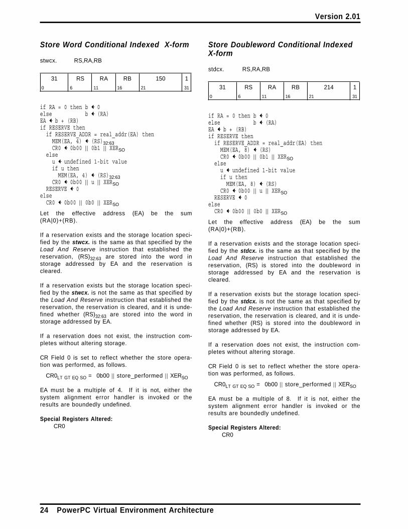
Store Word Conditional Indexed X-form
stwcx. RS,RA,RB
31 RS RA RB 150 1
0 6 11 16 21 31
if RA = 0 then b ← 0else b ← (RA)EA ← b + (RB)if RESERVE then
if RESERVE_ADDR = real_addr(EA) thenMEM(EA, 4) ← (RS)32:63CR0 ← 0b00 | | 0b1 | | XERSO
elseu ← undefined 1-bit valueif u then
MEM(EA, 4) ← (RS)32:63CR0 ← 0b00 | | u | | XERSO
RESERVE ← 0else
CR0 ← 0b00 | | 0b0 | | XERSO
Let the effective address (EA) be the sum(RA|0)+(RB).
If a reservation exists and the storage location speci-fied by the stwcx. is the same as that specified by theLoad And Reserve instruction that established thereservation, (RS)32:63 are stored into the word instorage addressed by EA and the reservation iscleared.
If a reservation exists but the storage location speci-fied by the stwcx. is not the same as that specified bythe Load And Reserve instruction that established thereservation, the reservation is cleared, and it is unde-fined whether (RS)32:63 are stored into the word instorage addressed by EA.
If a reservation does not exist, the instruction com-pletes without altering storage.
CR Field 0 is set to reflect whether the store opera-tion was performed, as follows.
CR0LT GT EQ SO = 0b00 | | store_performed | | XERSO
EA must be a multiple of 4. If it is not, either thesystem alignment error handler is invoked or theresults are boundedly undefined.
Special Registers Altered:CR0
Store Doubleword Conditional IndexedX-form
stdcx. RS,RA,RB
31 RS RA RB 214 1
0 6 11 16 21 31
if RA = 0 then b ← 0else b ← (RA)EA ← b + (RB)if RESERVE then
if RESERVE_ADDR = real_addr(EA) thenMEM(EA, 8) ← (RS)CR0 ← 0b00 | | 0b1 | | XERSO
elseu ← undefined 1-bit valueif u then
MEM(EA, 8) ← (RS)CR0 ← 0b00 | | u | | XERSO
RESERVE ← 0else
CR0 ← 0b00 | | 0b0 | | XERSO
Let the effective address (EA) be the sum(RA|0)+(RB).
If a reservation exists and the storage location speci-fied by the stdcx. is the same as that specified by theLoad And Reserve instruction that established thereservation, (RS) is stored into the doubleword instorage addressed by EA and the reservation iscleared.
If a reservation exists but the storage location speci-fied by the stdcx. is not the same as that specified bythe Load And Reserve instruction that established thereservation, the reservation is cleared, and it is unde-fined whether (RS) is stored into the doubleword instorage addressed by EA.
If a reservation does not exist, the instruction com-pletes without altering storage.
CR Field 0 is set to reflect whether the store opera-tion was performed, as follows.
CR0LT GT EQ SO = 0b00 | | store_performed | | XERSO
EA must be a multiple of 8. If it is not, either thesystem alignment error handler is invoked or theresults are boundedly undefined.
Special Registers Altered:CR0
24 PowerPC Virtual Environment Architecture

Version 2.01
3.3.3 Memory Barrier Instructions
The Memory Barrier instructions can be used tocontrol the order in which storage accesses are per-formed. Additional information about theseinstructions and about related aspects of storagemanagement can be found in Book III, PowerPC Oper-ating Environment Architecture.
Extended mnemonics for Synchronize
Extended mnemonics are provided for the Synchro-nize instruction so that it can be coded with the Lvalue as part of the mnemonic rather than as anumeric operand. These are shown as examples withthe instruction. See Appendix A, “AssemblerExtended Mnemonics” on page 37.
Synchronize X-form
sync L
[POWER mnemonic: dcs]
31 /// L /// /// 598 /
0 6 9 11 16 21 31
The sync instruction creates a memory barrier (seeSection 1.7.1). The set of storage accesses that isordered by the memory barrier depends on the valueof the L field.
L = 0 (“heavyweight sync”)The memory barrier provides an ordering func-tion for the storage accesses associated with allinstructions that are executed by the processorexecuting the sync instruction. The applicablepairs are all pairs ai,bj in which bj is a dataaccess, except that if ai is the storage accesscaused by an icbi instruction then bj may be per-formed with respect to the processor executingthe sync instruction before ai is performed withrespect to that processor.
L = 1 (“lightweight sync”)The memory barrier provides an ordering func-tion for the storage accesses caused by Load,Store, and dcbz instructions that are executed bythe processor executing the sync instruction andfor which the specified storage location is instorage that is Memory Coherence Required andis neither Write Through Required nor CachingInhibited. The applicable pairs are all pairs ai,bjof such accesses except those in which ai is anaccess caused by a Store or dcbz instruction andbj is an access caused by a Load instruction.
L = 2The set of storage accesses that is ordered bythe memory barrier is described in the sectionentitled “Synchronize Instruction” in Book III, asare additional properties of the sync instructionwith L=2 .
The ordering done by the memory barrier is cumula-tive.
The sync instruction may complete before storageaccesses associated with instructions preceding thesync instruction have been performed.
If L=0 , the sync instruction has the following addi-tional properties.
■ Executing the sync instruction ensures that allinstructions preceding the sync instruction havecompleted before the sync instruction completes,and that no subsequent instructions are initiateduntil after the sync instruction completes.
■ The sync instruction is execution synchronizing(see Book III, PowerPC Operating EnvironmentArchitecture). However, address translation andreference and change recording (see Book III)associated with subsequent instructions may beperformed before the sync instruction completes.
■ The memory barrier provides the additionalordering function such that if a given instructionthat is the result of a Store in set B is executed,all applicable storage accesses in set A havebeen performed with respect to the processorexecuting the instruction to the extent required bythe associated memory coherence properties.The single exception is that any storage access inset A that is caused by an icbi instruction exe-cuted by the processor executing the syncinstruction (P1) may not have been performedwith respect to P1 (see the description of the icbiinstruction on page 17).
The cumulative properties of the barrier apply tothe execution of the given instruction as theywould to a Load that returned a value that wasthe result of a Store in set B.
The value L = 3 is reserved, and the results of exe-cuting a sync instruction with L = 3 are boundedlyundefined.
Special Registers Altered:None
Chapter 3. Storage Control Instructions 25

Version 2.01
Extended Mnemonics:
Extended mnemonics for Synchronize:
Extended: Equivalent to:
sync sync 0lwsync sync 1ptesync sync 2
Except in the sync instruction description in thissection, references to “ sync” in Books I − III implyL = 0 unless otherwise stated or obvious from context(the appropriate extended mnemonics are used whenthe other L values are intended).
Programming Note
Section 1.8 on page 10 contains a detaileddescription of how to modify instructions such thata well-defined result is obtained.
Programming Note
sync serves as both a basic and an extendedmnemonic. The Assembler will recognize a syncmnemonic with one operand as the basic form,and a sync mnemonic with no operand as theextended form. In the extended form the Loperand is omitted and assumed to be 0.
Programming Note
The sync instruction can be used to ensure thatall stores into a data structure, caused by Storeinstructions executed in a “critical section” of aprogram, will be performed with respect toanother processor before the store that releasesthe lock is performed with respect to thatprocessor; see Section B.2, “Lock Acquisition andRelease, and Related Techniques” on page 41.
The memory barrier created by a sync instructionwith L = 0 or L = 1 does not order implicit storageaccesses. The memory barrier created by a syncinstruction with any L value does not orderinstruction fetches.
(The memory barrier created by a sync instructionwith L = 0 — or L=2 ; see Book III — appears toorder instruction fetches for instructions pre-ceding the sync instruction with respect to dataaccesses caused by instructions following thesync instruction. However, this ordering is a con-sequence of the first “additional property” of syncwith L=0 , not a property of the memory barrier.)
In order to obtain the best performance acrossthe widest range of implementations, the pro-grammer should use either the sync instructionwith L = 1 or the eieio instruction if either of theseis sufficient for his needs; otherwise he should usesync with L=0 . sync with L = 2 should not beused by application programs.
Programming Note
The functions provided by sync with L = 1 are astrict subset of those provided by sync with L=0 .(The functions provided by sync with L = 2 are astrict superset of those provided by sync withL=0 ; see Book III.)
26 PowerPC Virtual Environment Architecture

Version 2.01
Enforce In-order Execution of I/O X-form
eieio
31 /// /// /// 854 /
0 6 11 16 21 31
The eieio instruction creates a memory barrier (seeSection 1.7.1), which provides an ordering function forthe storage accesses caused by Load, Store, dcbz,eciwx, and ecowx instructions executed by theprocessor executing the eieio instruction. Thesestorage accesses are divided into two sets, which areordered separately. The storage access caused by aneciwx instruction is ordered as a load, and thestorage access caused by a dcbz or ecowx instructionis ordered as a store.
1. Loads and stores to storage that is both CachingInhibited and Guarded, and stores to mainstorage caused by stores to storage that is WriteThrough Required
The applicable pairs are all pairs ai,bj of suchaccesses.
The ordering done by the memory barrier foraccesses in this set is not cumulative.
2. Stores to storage that is Memory CoherenceRequired and is neither Write Through Requirednor Caching Inhibited
The applicable pairs are all pairs ai,bj of suchaccesses.
The ordering done by the memory barrier foraccesses in this set is cumulative.
The eieio instruction may complete before storageaccesses associated with instructions preceding theeieio instruction have been performed.
Special Registers Altered:None
Programming Note
The eieio instruction is intended for use in man-aging shared data structures (see Appendix B,“Programming Examples for Sharing Storage” onpage 39), in doing memory-mapped I/O, and inpreventing load/store combining operations inmain storage (see Section 1.6, “Storage ControlAttributes” on page 4).
Because stores to storage that is both CachingInhibited and Guarded are performed in programorder (see Section 1.7.1, “Storage AccessOrdering” on page 6), eieio is needed for suchstorage only when loads must be ordered withrespect to stores or with respect to other loads, orwhen load/store combining operations must beprevented.
For accesses in set 1, ai and bj need not be thesame kind of access or be to storage having thesame storage control attributes. For example, aican be a load to Caching Inhibited, Guardedstorage, and bj a store to Write Through Requiredstorage.
If stronger ordering is desired than that providedby eieio, the sync instruction must be used, withthe appropriate value in the L field.
Programming Note
The functions provided by eieio are a strict subsetof those provided by sync with L=0 . The func-tions provided by eieio for its second set are astrict subset of those provided by sync with L=1 .
Chapter 3. Storage Control Instructions 27

Version 2.01
28 PowerPC Virtual Environment Architecture
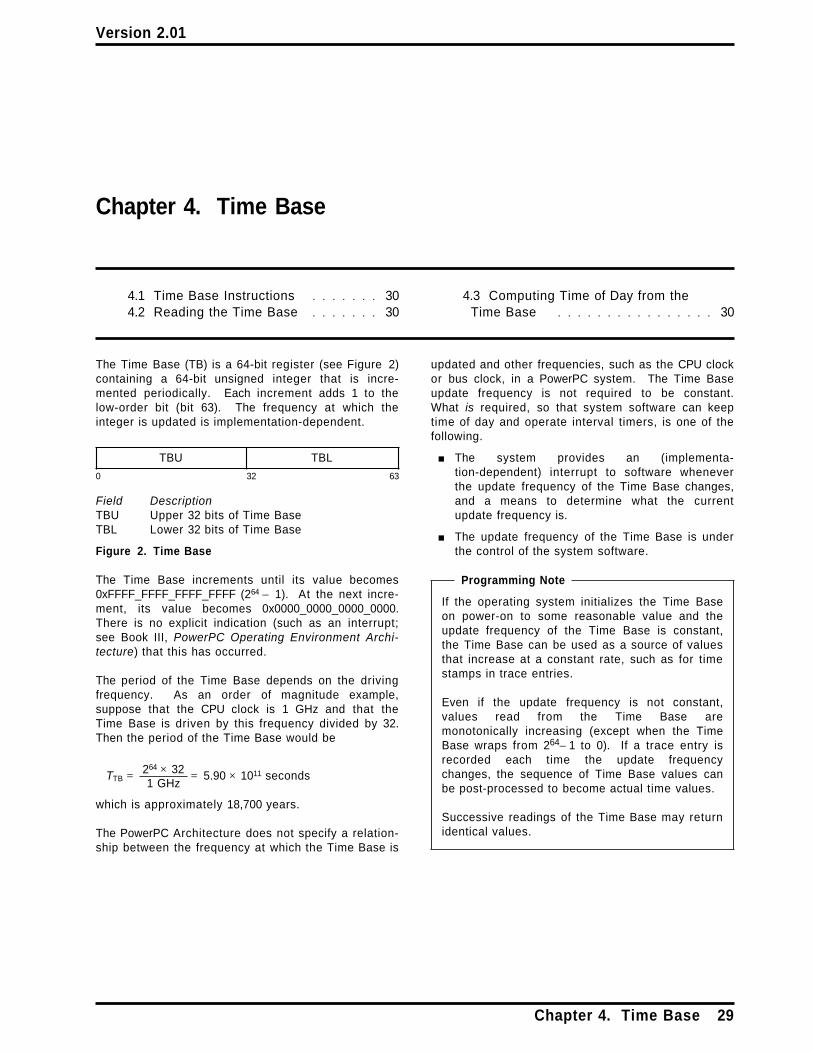
Version 2.01
Chapter 4. Time Base
4.1 Time Base Instructions . . . . . . . 304.2 Reading the Time Base . . . . . . . 30
4.3 Computing Time of Day from theTime Base . . . . . . . . . . . . . . . . 30
The Time Base (TB) is a 64-bit register (see Figure 2)containing a 64-bit unsigned integer that is incre-mented periodically. Each increment adds 1 to thelow-order bit (bit 63). The frequency at which theinteger is updated is implementation-dependent.
TBU TBL
0 32 63
Field DescriptionTBU Upper 32 bits of Time BaseTBL Lower 32 bits of Time Base
Figure 2. Time Base
The Time Base increments until its value becomes0xFFFF_FFFF_FFFF_FFFF (264 − 1). At the next incre-ment, its value becomes 0x0000_0000_0000_0000.There is no explicit indication (such as an interrupt;see Book III, PowerPC Operating Environment Archi-tecture) that this has occurred.
The period of the Time Base depends on the drivingfrequency. As an order of magnitude example,suppose that the CPU clock is 1 GHz and that theTime Base is driven by this frequency divided by 32.Then the period of the Time Base would be
TTB = 264 × 321 GHz
= 5.90 × 10¹¹ seconds
which is approximately 18,700 years.
The PowerPC Architecture does not specify a relation-ship between the frequency at which the Time Base is
updated and other frequencies, such as the CPU clockor bus clock, in a PowerPC system. The Time Baseupdate frequency is not required to be constant.What is required, so that system software can keeptime of day and operate interval timers, is one of thefollowing.
■ The system provides an (implementa-tion-dependent) interrupt to software wheneverthe update frequency of the Time Base changes,and a means to determine what the currentupdate frequency is.
■ The update frequency of the Time Base is underthe control of the system software.
Programming Note
If the operating system initializes the Time Baseon power-on to some reasonable value and theupdate frequency of the Time Base is constant,the Time Base can be used as a source of valuesthat increase at a constant rate, such as for timestamps in trace entries.
Even if the update frequency is not constant,values read from the Time Base aremonotonically increasing (except when the TimeBase wraps from 264− 1 to 0). If a trace entry isrecorded each time the update frequencychanges, the sequence of Time Base values canbe post-processed to become actual time values.
Successive readings of the Time Base may returnidentical values.
Chapter 4. Time Base 29

Version 2.01
4.1 Time Base Instructions
Extended mnemonics
Extended mnemonics are provided provided for theMove From Time Base instruction so that it can becoded with the TBR name as part of the mnemonicrather than as a numeric operand. See the appendixentitled “Assembler Extended Mnemonics” in Book III,PowerPC Operating Environment Architecture.
Move From Time Base XFX-form
mftb RT,TBR
31 RT tbr 371 /
0 6 11 21 31
n ← tbr5:9 | | tbr0:4if n = 268 then
RT ← TBelse if n = 269 then
RT ← 320 | | TB0:31
The TBR field denotes either the Time Base or TimeBase Upper, encoded as shown in the table below.The contents of the designated register are placedinto register RT. When reading Time Base Upper, thehigh-order 32 bits of register RT are set to zero.
TBR* Registerdecimal tbr5:9 tbr0:4 Name
268 01000 01100 TB269 01000 01101 TBU
* Note that the order of the two 5-bithalves of the TBR number is reversed.
If the TBR field contains any value other than one ofthe values shown above then one of the followingoccurs.
■ The system illegal instruction error handler isinvoked.
■ The system privileged instruction error handler isinvoked.
■ The results are boundedly undefined.
Special Registers Altered:None
Extended Mnemonics:
Extended mnemonics for Move From Time Base:
Extended: Equivalent to:
mftb Rx mftb Rx,268mftbu Rx mftb Rx,269
Programming Note
mftb serves as both a basic and an extendedmnemonic. The Assembler will recognize an mftbmnemonic with two operands as the basic form,and an mftb mnemonic with one operand as theextended form. In the extended form the TBRoperand is omitted and assumed to be 268 (thevalue that corresponds to TB).
Compiler and Assembler Note
The TBR number coded in assembler languagedoes not appear directly as a 10-bit binarynumber in the instruction. The number coded issplit into two 5-bit halves that are reversed in theinstruction, with the high-order 5 bits appearing inbits 16:20 of the instruction and the low-order 5bits in bits 11:15.
4.2 Reading the Time Base
The contents of the Time Base can be read into aGPR by the mftb extended mnemonic. To read thecontents of the Time Base into register Rx, execute:
mftb Rx
Reading the Time Base has no effect on the value itcontains or on the periodic incrementing of that value.
4.3 Computing Time of Dayfrom the Time Base
Since the update frequency of the Time Base is imple-mentation-dependent, the algorithm for converting thecurrent value in the Time Base to time of day is alsoimplementation-dependent.
As an example, assume that the Time Base is incre-mented at a constant rate of once for every 32 cyclesof a 1 GHz CPU instruction clock. What is wanted isthe pair of 32-bit values comprising a POSIX standardclock:1 the number of whole seconds that have passed
1 Described in POSIX Draft Standard P1003.4/D12, Draft Standard for Information Technology -- Portable Operating System Interface (POSIX) --Part 1: System Application Program Interface (API) - Amendment 1: Realtime Extension [ C Language] . Institute of Electrical and ElectronicsEngineers, Inc., Feb. 1992.
30 PowerPC Virtual Environment Architecture

Version 2.01
since midnight January 0, 1970, and the remainingfraction of a second expressed as a number ofnanoseconds.
Assume that:
■ The value 0 in the Time Base represents the starttime of the POSIX clock (if this is not true, asimple 64-bit subtraction will make it so).
■ The integer constant ticks_per_sec contains thevalue
1 GHz32
= 31,250,000
which is the number of times the Time Base isupdated each second.
■ The integer constant ns_adj contains the value
1,000,000,00031,250,000
= 32
which is the number of nanoseconds per tick ofthe Time Base.
The POSIX clock can be computed with an instructionsequence such as this:
mftb Ry # Ry = Time Baselwz Rx,ticks_per_secdivd Rz,Ry,Rx # Rz = whole secondsstw Rz,posix_secmulld Rz,Rz,Rx # Rz = quotient * divisorsub Rz,Ry,Rz # Rz = excess tickslwz Rx,ns_adjmulld Rz,Rz,Rx # Rz = excess nanosecondsstw Rz,posix_ns
Non-constant update frequency
In a system in which the update frequency of the TimeBase may change over time, it is not possible toconvert an isolated Time Base value into time of day.Instead, a Time Base value has meaning only withrespect to the current update frequency and the timeof day that the update frequency was last changed.Each time the update frequency changes, either thesystem software is notified of the change via an inter-rupt (see Book III, PowerPC Operating EnvironmentArchitecture), or the change was instigated by thesystem software itself. At each such change, thesystem software must compute the current time ofday using the old update frequency, compute a newvalue of ticks_per_sec for the new frequency, andsave the time of day, Time Base value, and tick rate.Subsequent calls to compute time of day use thecurrent Time Base value and the saved data.
Chapter 4. Time Base 31

Version 2.01
32 PowerPC Virtual Environment Architecture

Version 2.01
Chapter 5. Optional Facilities and Instructions
5.1 External Control . . . . . . . . . . . 335.1.1 External Access Instructions . . . 345.2 Storage Control Instructions . . . . 35
5.2.1 Cache Management Instructions 355.2.1.1 Data Cache Instruction . . . . . 355.3 Little-Endian . . . . . . . . . . . . . . 36
The facilities and instructions described in thischapter are optional. An implementation may provideall, some, or none of them, except as describedbelow.
5.1 External Control
The External Control facility permits a program tocommunicate with a special-purpose device. Twoinstructions are provided, both of which must beimplemented if the facility is provided.
■ External Control In Word Indexed (eciwx), whichdoes the following:
— Computes an effective address (EA) as forany X-form instruction
— Validates the EA as would be done for a loadfrom that address
— Translates the EA to a real address— Transmits the real address to the device— Accepts a word of data from the device and
places it into a General Purpose Register
■ External Control Out Word Indexed (ecowx),which does the following:
— Computes an effective address (EA) as forany X-form instruction
— Validates the EA as would be done for astore to that address
— Translates the EA to a real address— Transmits the real address and a word of
data from a General Purpose Register to thedevice
Permission to execute these instructions and identifi-cation of the target device are controlled by twofields, called the E bit and the RID field respectively.
If attempt is made to execute either of theseinstructions when E = 0 the system data storage errorhandler is invoked. The location of these fields isdescribed in Book III, PowerPC Operating Environ-ment Architecture.
The storage access caused by eciwx and ecowx isperformed as though the specified storage location isCaching Inhibited and Guarded, and is neither WriteThrough Required nor Memory Coherence Required.
Interpretation of the real address transmitted byeciwx and ecowx and of the 32-bit value transmittedby ecowx is up to the target device, and is not speci-fied by the PowerPC Architecture. See the SystemArchitecture documentation for a given PowerPCsystem for details on how the External Control facilitycan be used with devices on that system.
Example
An example of a device designed to be used with theExternal Control facility might be a graphics adapter.The ecowx instruction might be used to send thedevice the translated real address of a buffer con-taining graphics data, and the word transmitted fromthe General Purpose Register might be control infor-mation that tells the adapter what operation toperform on the data in the buffer. The eciwx instruc-tion might be used to load status information from theadapter.
A device designed to be used with the ExternalControl facility may also recognize events that indi-cate that the address translation being used by theprocessor has changed. In this case the operatingsystem need not “pin ” the area of storage identifiedby an eciwx or ecowx instruction (i.e., need notprotect it from being paged out).
Chapter 5. Optional Facilities and Instructions 33

Version 2.01
5.1.1 External Access Instructions
In the instruction descriptions the statements “thisinstruction is treated as a Load” and “this instructionis treated as a Store” have the same meanings as for
the Cache Management instructions; see Section 3.2,“Cache Management Instructions” on page 16.
External Control In Word IndexedX-form
eciwx RT,RA,RB
31 RT RA RB 310 /0 6 11 16 21 31
if RA = 0 then b ← 0else b ← (RA)EA ← b + (RB)raddr ← address translation of EAsend load word request for raddr to
device identified by RIDRT ← 320 | | word from device
Let the effective address (EA) be the sum(RA|0)+(RB).
A load word request for the real address corre-sponding to EA is sent to the device identified by RID,bypassing the cache. The word returned by the deviceis placed into RT32:63. RT0:31 are set to 0.
The E bit must be 1. If it is not, the data storage errorhandler is invoked.
EA must be a multiple of 4. If it is not, either thesystem alignment error handler is invoked or theresults are boundedly undefined.
This instruction is treated as a Load.
See Book III, PowerPC Operating Environment Archi-tecture for additional information about this instruc-tion.
Special Registers Altered:None
Programming Note
The eieio instruction can be used to ensure thatthe storage accesses caused by eciwx and ecowxare performed in program order with respect toother Caching Inhibited and Guarded storageaccesses.
External Control Out Word IndexedX-form
ecowx RS,RA,RB
31 RS RA RB 438 /0 6 11 16 21 31
if RA = 0 then b ← 0else b ← (RA)EA ← b + (RB)raddr ← address translation of EAsend store word request for raddr to
device identified by RIDsend (RS)32:63 to device
Let the effective address (EA) be the sum(RA|0)+(RB).
A store word request for the real address corre-sponding to EA and the contents of RS32:63 are sent tothe device identified by RID, bypassing the cache.
The E bit must be 1. If it is not, the data storage errorhandler is invoked.
EA must be a multiple of 4. If it is not, either thesystem alignment error handler is invoked or theresults are boundedly undefined.
This instruction is treated as a Store, except that itsstorage access is not performed in program orderwith respect to accesses to other Caching Inhibitedand Guarded storage locations unless software explic-itly imposes that order.
See Book III, PowerPC Operating Environment Archi-tecture for additional information about this instruc-tion.
Special Registers Altered:None
34 PowerPC Virtual Environment Architecture

Version 2.01
5.2 Storage Control Instructions
5.2.1 Cache Management Instructions
5.2.1.1 Data Cache Instruction
The optional version of the Data Cache Block Touchinstruction includes a TH (Touch Hint) field, whichpermits a program to provide a hint that a sequenceof data cache blocks is likely to be needed soon. Thesequence is called a “data stream”.
Data Cache Block Touch X-form
dcbt RA,RB,TH
31 /// TH RA RB 278 /
0 6 9 11 16 21 31
Let the effective address (EA) be the sum(RA|0)+(RB).
The dcbt instruction provides a hint that the programwill probably soon load from the storage locationsspecified by EA and the TH field. The hint is ignoredfor storage locations that are Caching Inhibited orGuarded.
The encodings of the TH field are as follows.
TH Description
00 The storage location is the block containing thebyte addressed by EA.
01 The storage locations are the block containingthe byte addressed by EA and sequentially fol-lowing blocks (i.e., the blocks containing thebytes addressed by EA + n × block_size, wheren = 0, 1, 2, ...).
10 Reserved
11 The storage locations are the block containingthe byte addressed by EA and sequentially pre-ceding blocks (i.e., the blocks containing thebytes addressed by EA − n × block_size, wheren = 0, 1, 2, ...).
The actions (if any) taken by the processor inresponse to the hint are not considered to be “causedby” or “associated with” the dcbt instruction (e.g.,dcbt is considered not to cause any data accesses).No means are provided by which software can syn-chronize these actions with the execution of the
instruction stream. For example, these actions arenot ordered by memory barriers.
This instruction is treated as a Load (see Section 3.2),except that the system data storage error handler isnot invoked, and reference and change recordingneed not be done.
Special Registers Altered:None
Programming Note
In response to the hint provided by dcbt, theprocessor may prefetch the specified storagelocations into the data cache, or take otheractions that reduce the latency of subsequentLoad instructions that refer to the locations.
Programming Note
dcbt serves as both a basic and an extendedmnemonic. The Assembler will recognize a dcbtmnemonic with three operands as the basic form,and a dcbt mnemonic with two operands as theextended form. In the extended form the THoperand is omitted and assumed to be 0b00.
Programming Note
If the TH field is set to 0b00, the instruction oper-ates as described in Section 3.2.2, “Data CacheInstructions” on page 18.
The TH field should not be set to 0b10, becausethat value may be assigned a meaning in somefuture version of the architecture.
Earlier implementations that do not support theoptional version of dcbt ignore the TH field (i.e.,treat it as if it were set to 0b00), and do not nec-essarily ignore the hint provided by dcbt if thespecified block is in storage that is Guarded andnot Caching Inhibited. Therefore a dcbt instruc-tion with TH1= 1 should not specify an EA in suchstorage if the program is to be run on such imple-mentations.
Chapter 5. Optional Facilities and Instructions 35

Version 2.01
Programming Note
Although optimal use of the data stream variantof dcbt (TH1= 1 ) depends on the characteristics ofthe prefetch mechanism and of the storage hier-archy (see Book IV), the programmer shouldassume that the following programming model issupported.
■ Data stream resources are allocated in round-robin fashion. Therefore dcbt instructions(with TH1= 1 ) should be executed for the leastimportant stream first and the most importantstream last. If this technique is used anddcbt instructions are executed for morestreams than the processor supports, themost important streams will be prefetched.
■ The prefetch mechanism paces prefetching ofa data stream with consumption of the pre-fetched data, prefetching only a limitednumber of blocks ahead of the block that iscurrently being loaded from by the program.As a consequence, when the program ceasesto load from successive blocks of the stream,prefetching of the stream ceases.
■ Certain conditions may cause prefetching tobe terminated for a data stream that theprogram is still using. However, the prefetchmechanism will subsequently detect that thestream is still being loaded from and willresume prefetching of the stream. Thereforethere is no need to code more than one dcbtinstruction (with TH1= 1 ) for the stream.
Although the dcbt instruction described in Section3.2.2 (equivalently, dcbt with TH=0b00) can beused to provide the same function as the datastream variant, the data stream variant may beeasier to use because only one instance of thedcbt instruction is needed per stream, instead ofone per cache block, and because the perform-ance of processing the stream is less sensitive tohow far ahead of the Load instructions the dcbtinstruction is placed.
5.3 Little-Endian
If the optional Little-Endian facility is implemented(see the section entitled “Little-Endian” in Book I,PowerPC User Instruction Set Architecture), the pro-grammer should assume the performance modeldescribed in Figure 3 with respect to the placement ofstorage operands that are accessed in Little-Endianmode.
Operand Boundary Crossing
Byte Cache VirtualSize Align. None Block Page2 Seg.
Integer
8 Byte 8 optimal − − −4 good good poor poor< 4 poor poor poor poor
4 Byte 4 optimal − − −< 4 good good poor poor
2 Byte 2 optimal − − −< 2 good good poor poor
1 Byte 1 optimal − − −
Float
8 Byte 8 optimal − − −4 good good poor poor< 4 poor poor poor poor
4 Byte 4 optimal − − −< 4 poor poor poor poor
1 If an instruction causes an access that is notatomic and any portion of the operand is instorage that is Write Through Required orCaching Inhibited, performance is likely to bepoor.
2 If the storage operand spans two virtual pagesthat have different storage control attributes,performance is likely to be poor.
Figure 3. Performance effects of storage operandplacement, Little-Endian mode
36 PowerPC Virtual Environment Architecture

Version 2.01
Appendix A. Assembler Extended Mnemonics
In order to make assembler language programssimpler to write and easier to understand, a set ofextended mnemonics and symbols is provided forcertain instructions. This appendix defines extended
mnemonics and symbols related to instructionsdefined in Book II.
Assemblers should provide the extended mnemonicsand symbols listed here, and may provide others.
A.1 Synchronize Mnemonics
The L field in the Synchronize instruction controls thescope of the synchronization function performed bythe instruction. Extended mnemonics are providedthat represent the L value in the mnemonic ratherthan requiring it to be coded as a numeric operand.
Note: sync serves as both a basic and an extendedmnemonic. The Assembler will recognize a syncmnemonic with one operand as the basic form, and async mnemonic with no operand as the extendedform. In the extended form the L operand is omittedand assumed to be 0.
sync (equivalent to: sync 0)lwsync (equivalent to: sync 1)ptesync (equivalent to: sync 2)
Appendix A. Assembler Extended Mnemonics 37

Version 2.01
38 PowerPC Virtual Environment Architecture

Version 2.01
Appendix B. Programming Examples for Sharing Storage
This appendix gives examples of how dependenciesand the Synchronization instructions can be used tocontrol storage access ordering when storage isshared between programs.
Many of the examples use extended mnemonics (e.g.,bne, bne-, cmpw) that are defined in the Appendixentitled “Assembler Extended Mnemonics” in Book I,PowerPC User Instruction Set Architecture.
Many of the examples use the Load And Reserve andStore Conditional instructions, in a sequence thatbegins with a Load And Reserve instruction and endswith a Store Conditional instruction (specifying thesame storage location as the Load Conditional) fol-lowed by a Branch Conditional instruction that testswhether the Store Conditional instruction succeeded.
In these examples it is assumed that contention forthe shared resource is low; the conditional branchesare optimized for this case by using “ + ” and “ − ” suf-fixes appropriately.
The examples deal with words; they can be used fordoublewords by changing all word-specific mnemonicsto the corresponding doubleword-specific mnemonics(e.g., lwarx to ldarx, cmpw to cmpd).
In this appendix it is assumed that all shared storagelocations are in storage that is Memory CoherenceRequired, and that the storage locations specified byLoad And Reserve and Store Conditional instructionsare in storage that is neither Write Through Requirednor Caching Inhibited.
B.1 Atomic Update Primitives
This section gives examples of how the Load AndReserve and Store Conditional instructions can beused to emulate atomic read/modify/write operations.
An atomic read/modify/write operation reads astorage location and writes its next value, which maybe a function of its current value, all as a single
atomic operation. The examples shown provide theeffect of an atomic read/modify/write operation, butuse several instructions rather than a single atomicinstruction.
Fetch and No-op
The “Fetch and No-op” primitive atomically loads thecurrent value in a word in storage.
In this example it is assumed that the address of theword to be loaded is in GPR 3 and the data loadedare returned in GPR 4.
loop: lwarx r4,0,r3 #load and reservestwcx. r4,0,r3 #store old value if
# still reservedbne− loop #loop if lost reservation
Note:
1. The stwcx., if it succeeds, stores to the targetlocation the same value that was loaded by thepreceding lwarx. While the store is redundant
with respect to the value in the location, itssuccess ensures that the value loaded by thelwarx is still the current value at the time thestwcx. is executed.
Fetch and Store
The “Fetch and Store” primitive atomically loads andreplaces a word in storage.
In this example it is assumed that the address of theword to be loaded and replaced is in GPR 3, the newvalue is in GPR 4, and the old value is returned inGPR 5.
loop: lwarx r5,0,r3 #load and reservestwcx. r4,0,r3 #store new value if
# still reservedbne− loop #loop if lost reservation
Appendix B. Programming Examples for Sharing Storage 39

Version 2.01
Fetch and Add
The “Fetch and Add” primitive atomically incrementsa word in storage.
In this example it is assumed that the address of theword to be incremented is in GPR 3, the increment isin GPR 4, and the old value is returned in GPR 5.
loop: lwarx r5,0,r3 #load and reserveadd r0,r4,r5 #increment wordstwcx. r0,0,r3 #store new value if
# still reservedbne− loop #loop if lost reservation
Fetch and AND
The “Fetch and AND” primitive atomically ANDs avalue into a word in storage.
In this example it is assumed that the address of theword to be ANDed is in GPR 3, the value to AND intoit is in GPR 4, and the old value is returned in GPR 5.
loop: lwarx r5,0,r3 #load and reserveand r0,r4,r5 #AND wordstwcx. r0,0,r3 #store new value if
# still reservedbne− loop #loop if lost reservation
Note:
1. The sequence given above can be changed toperform another Boolean operation atomically ona word in storage, simply by changing the andinstruction to the desired Boolean instruction (or,xor, etc.).
Test and Set
This version of the “Test and Set” primitive atom-ically loads a word from storage, sets the word instorage to a nonzero value if the value loaded is zero,and sets the EQ bit of CR Field 0 to indicate whetherthe value loaded is zero.
In this example it is assumed that the address of theword to be tested is in GPR 3, the new value(nonzero) is in GPR 4, and the old value is returned inGPR 5.
loop: lwarx r5,0,r3 #load and reservecmpwi r5,0 #done if wordbne− $+12 # not equal to 0stwcx. r4,0,r3 #try to store non-0bne− loop #loop if lost reservation
Compare and Swap
The “Compare and Swap” primitive atomically com-pares a value in a register with a word in storage, ifthey are equal stores the value from a second reg-ister into the word in storage, if they are unequalloads the word from storage into the first register,and sets the EQ bit of CR Field 0 to indicate the resultof the comparison.
In this example it is assumed that the address of theword to be tested is in GPR 3, the comparand is inGPR 4 and the old value is returned there, and thenew value is in GPR 5.
loop: lwarx r6,0,r3 #load and reservecmpw r4,r6 #1st 2 operands equal?bne− exit #skip if notstwcx. r5,0,r3 #store new value if
# still reservedbne− loop #loop if lost reservation
exit: mr r4,r6 #return value from storage
Notes:
1. The semantics given for “Compare and Swap”above are based on those of the IBM System/370Compare and Swap instruction. Other architec-tures may define a Compare and Swap instructiondifferently.
2. “Compare and Swap” is shown primarily for ped-agogical reasons. It is useful on machines thatlack the better synchronization facilities providedby lwarx and stwcx.. A major weakness of aSystem/370-style Compare and Swap instructionis that, although the instruction itself is atomic, itchecks only that the old and current values of theword being tested are equal, with the result thatprograms that use such a Compare and Swap tocontrol a shared resource can err if the word hasbeen modified and the old value subsequentlyrestored. The sequence shown above has thesame weakness.
3. In some applications the second bne- instructionand/or the mr instruction can be omitted. Thebne- is needed only if the application requiresthat if the EQ bit of CR Field 0 on exit indicates“not equal” then (r4) and (r6) are in fact notequal. The mr is needed only if the applicationrequires that if the comparands are not equalthen the word from storage is loaded into the reg-ister with which it was compared (rather than intoa third register). If either or both of theseinstructions is omitted, the resulting Compare andSwap does not obey System/370 semantics.
40 PowerPC Virtual Environment Architecture

Version 2.01
B.2 Lock Acquisition and Release, and Related Techniques
This section gives examples of how dependencies andthe Synchronization instructions can be used to imple-
ment locks, import and export barriers, and similarconstructs.
B.2.1 Lock Acquisition and ImportBarriers
An “ import barrier” is an instruction or sequence ofinstructions that prevents storage accesses caused byinstructions following the barrier from being per-formed before storage accesses that acquire a lockhave been performed. An import barrier can be usedto ensure that a shared data structure protected by alock is not accessed until the lock has been acquired.A sync instruction can be used as an import barrier,but the approaches shown below will generally yieldbetter performance because they order only the rele-vant storage accesses.
B.2.1.1 Acquire Lock and Import SharedStorage
If lwarx and stwcx. instructions are used to obtain thelock, an import barrier can be constructed by placingan isync instruction immediately following the loopcontaining the lwarx and stwcx.. The followingexample uses the “Compare and Swap” primitive toacquire the lock.
In this example it is assumed that the address of thelock is in GPR 3, the value indicating that the lock isfree is in GPR 4, the value to which the lock should beset is in GPR 5, the old value of the lock is returned inGPR 6, and the address of the shared data structureis in GPR 9.
loop: lwarx r6,0,r3 #load lock and reservecmpw r4,r6 #skip ahead ifbne− wait # lock not freestwcx. r5,0,r3 #try to set lockbne− loop #loop if lost reservationisync #import barrierlwz r7,data1(r9) #load shared data..
wait: ... #wait for lock to free
The second bne- does not complete until CR0 hasbeen set by the stwcx.. The stwcx. does not set CR0until it has completed (successfully or unsuccessfully).The lock is acquired when the stwcx. completes suc-cessfully. Together, the second bne- and the subse-quent isync create an import barrier that prevents theload from “data1” from being performed until thebranch has been resolved not to be taken.
If the shared data structure is in storage that isneither Write Through Required nor Caching Inhibited,an lwsync instruction can be used instead of the isyncinstruction. If lwsync is used, the load from “data1”may be performed before the stwcx.. But if thestwcx. fails, the second branch is taken and the lwarxis reexecuted. If the stwcx. succeeds, the valuereturned by the load from “data1” is valid even if theload is performed before the stwcx., because thelwsync ensures that the load is performed after theinstance of the lwarx that created the reservationused by the successful stwcx..
B.2.1.2 Obtain Pointer and ImportShared Storage
If lwarx and stwcx. instructions are used to obtain apointer into a shared data structure, an import barrieris not needed if all the accesses to the shared datastructure depend on the value obtained for thepointer. The following example uses the “Fetch andAdd” primitive to obtain and increment the pointer.
In this example it is assumed that the address of thepointer is in GPR 3, the value to be added to thepointer is in GPR 4, and the old value of the pointer isreturned in GPR 5.
loop: lwarx r5,0,r3 #load pointer and reserveadd r0,r4,r5 #increment the pointerstwcx. r0,0,r3 #try to store new valuebne− loop #loop if lost reservationlwz r7,data1(r5) #load shared data
The load from “data1” cannot be performed until thepointer value has been loaded into GPR 5 by thelwarx. The load from “data1” may be performedbefore the stwcx.. But if the stwcx. fails, the branchis taken and the value returned by the load from“data1” is discarded. If the stwcx. succeeds, thevalue returned by the load from “data1” is valid evenif the load is performed before the stwcx., becausethe load uses the pointer value returned by theinstance of the lwarx that created the reservationused by the successful stwcx..
An isync instruction could be placed between the bne-and the subsequent lwz, but no isync is needed if allaccesses to the shared data structure depend on thevalue returned by the lwarx.
Appendix B. Programming Examples for Sharing Storage 41

Version 2.01
B.2.2 Lock Release and ExportBarriers
An “export barrier” is an instruction or sequence ofinstructions that prevents the store that releases alock from being performed before stores caused byinstructions preceding the barrier have been per-formed. An export barrier can be used to ensure thatall stores to a shared data structure protected by alock will be performed with respect to any otherprocessor before the store that releases the lock isperformed with respect to that processor.
B.2.2.1 Export Shared Storage andRelease Lock
A sync instruction can be used as an export barrierindependent of the storage control attributes (e.g.,presence or absence of the Caching Inhibited attri-bute) of the storage containing the shared data struc-ture. Because the lock must be in storage that isneither Write Through Required nor Caching Inhibited,if the shared data structure is in storage that is WriteThrough Required or Caching Inhibited a sync instruc-tion must be used as the export barrier.
In this example it is assumed that the shared datastructure is in storage that is Caching Inhibited, theaddress of the lock is in GPR 3, the value indicatingthat the lock is free is in GPR 4, and the address ofthe shared data structure is in GPR 9.
stw r7,data1(r9) #store shared data (last)sync #export barrierstw r4,lock(r3) #release lock
The sync ensures that the store that releases the lockwill not be performed with respect to any otherprocessor until all stores caused by instructions pre-ceding the sync have been performed with respect tothat processor.
B.2.2.2 Export Shared Storage andRelease Lock using eieio or lwsync
If the shared data structure is in storage that isneither Write Through Required nor Caching Inhibited,an eieio instruction can be used as the export barrier.Using eieio rather than sync will yield better perform-ance in most systems.
In this example it is assumed that the shared datastructure is in storage that is neither Write ThroughRequired nor Caching Inhibited, the address of thelock is in GPR 3, the value indicating that the lock isfree is in GPR 4, and the address of the shared datastructure is in GPR 9.
stw r7,data1(r9) #store shared data (last)eieio #export barrierstw r4,lock(r3) #release lock
The eieio ensures that the store that releases the lockwill not be performed with respect to any otherprocessor until all stores caused by instructions pre-ceding the eieio have been performed with respect tothat processor.
However, for storage that is neither Write ThroughRequired nor Caching Inhibited, eieio orders onlystores and has no effect on loads. If the portion ofthe program preceding the eieio contains loads fromthe shared data structure and the stores to theshared data structure do not depend on the valuesreturned by those loads, the store that releases thelock could be performed before those loads. If it isnecessary to ensure that those loads are performedbefore the store that releases the lock, lwsync shouldbe used instead of eieio. Alternatively, the techniquedescribed in Section B.2.3 can be used.
B.2.3 Safe Fetch
If a load must be performed before a subsequentstore (e.g., the store that releases a lock protecting ashared data structure), a technique similar to the fol-lowing can be used.
In this example it is assumed that the address of thestorage operand to be loaded is in GPR 3, the con-tents of the storage operand are returned in GPR 4,and the address of the storage operand to be storedis in GPR 5.
lwz r4,0(r3) #load shared datacmpw r4,r4 #set CR0 to "equal"bne− $−8 #branch never takenstw r7,0(r5) #store other shared data
An alternative is to use a technique similar to thatdescribed in Section B.2.1.2, by causing the stw todepend on the value returned by the lwz and omittingthe cmpw and bne-. The dependency could becreated by ANDing the value returned by the lwz withzero and then adding the result to the value to bestored by the stw. If both storage operands are instorage that is neither Write Through Required norCaching Inhibited, another alternative is to replacethe cmpw and bne- with an lwsync instruction.
42 PowerPC Virtual Environment Architecture

Version 2.01
B.3 List Insertion
This section shows how the lwarx and stwcx.instructions can be used to implement simpleinsertion into a singly linked list. (Complicated listinsertion, in which multiple values must be changedatomically, or in which the correct order of insertiondepends on the contents of the elements, cannot beimplemented in the manner shown below and requiresa more complicated strategy such as using locks.)
The “next element pointer” from the list element afterwhich the new element is to be inserted, here calledthe “parent element”, is stored into the new element,so that the new element points to the next element inthe list; this store is performed unconditionally. Thenthe address of the new element is conditionally storedinto the parent element, thereby adding the newelement to the list.
In this example it is assumed that the address of theparent element is in GPR 3, the address of the newelement is in GPR 4, and the next element pointer isat offset 0 from the start of the element. It is alsoassumed that the next element pointer of each listelement is in a reservation granule separate fromthat of the next element pointer of all other list ele-ments.
loop: lwarx r2,0,r3 #get next pointerstw r2,0(r4) #store in new elementeieio #order stw before stwcx.stwcx. r4,0,r3 #add new element to listbne− loop #loop if stwcx. failed
In the preceding example, lwsync can be used insteadof eieio.
In the preceding example, if two list elements havenext element pointers in the same reservationgranule then, in a multiprocessor, “ l ivelock” canoccur. (Livelock is a state in which processorsinteract in a way such that no processor makesforward progress.)
If it is not possible to allocate list elements such thateach element's next element pointer is in a differentreservation granule, then livelock can be avoided byusing the following, more complicated, sequence.
lwz r2,0(r3) #get next pointerloop1: mr r5,r2 #keep a copy
stw r2,0(r4) #store in new elementsync #order stw before stwcx.
# and before lwarxloop2: lwarx r2,0,r3 #get it again
cmpw r2,r5 #loop if changed (someonebne− loop1 # else progressed)stwcx. r4,0,r3 #add new element to listbne− loop2 #loop if failed
In the preceding example, livelock is avoided by thefact that each processor reexecutes the stw only ifsome other processor has made forward progress.
B.4 Notes
1. To increase the likelihood that forward progressis made, it is important that looping onlwarx/stwcx. pairs be minimized. For example, inthe “Test and Set” sequence shown in SectionB.1, this is achieved by testing the old valuebefore attempting the store; were the orderreversed, more stwcx. instructions might be exe-cuted, and reservations might more often be lostbetween the lwarx and the stwcx..
2. The manner in which lwarx and stwcx. are com-municated to other processors and mechanisms,and between levels of the storage hierarchywithin a given processor, is implementa-tion-dependent. In some implementations per-formance may be improved by minimizing loopingon a lwarx instruction that fails to return adesired value. For example, in the “Test andSet” sequence shown in Section B.1, if the pro-grammer wishes to stay in the loop until the wordloaded is zero, he could change the “bne- $ + 1 2 ”to “bne- loop”. However, in some implementa-tions better performance may be obtained byusing an ordinary Load instruction to do the initialchecking of the value, as follows.
loop: lwz r5,0(r3) #load the wordcmpwi r5,0 #loop back if wordbne− loop # not equal to 0lwarx r5,0,r3 #try again, reservingcmpwi r5,0 # (likely to succeed)bne− loopstwcx. r4,0,r3 #try to store non-0bne− loop #loop if lost reserv'n
3. In a multiprocessor, livelock is possible if there isa Store instruction (or any other instruction thatcan clear another processor's reservation; seeSection 1.7.3.1) between the lwarx and the stwcx.of a lwarx/stwcx. loop and any byte of thestorage location specified by the Store is in thereservation granule. For example, the first codesequence shown in Section B.3 can cause livelockif two list elements have next element pointers inthe same reservation granule.
Appendix B. Programming Examples for Sharing Storage 43

Version 2.01
44 PowerPC Virtual Environment Architecture

Version 2.01
Appendix C. Cross-Reference for Changed POWERMnemonics
The following table lists the POWER instruction mne-monics that have been changed in the PowerPCVirtual Environment Architecture, sorted by POWERmnemonic.
To determine the PowerPC mnemonic for one of thesePOWER mnemonics, find the POWER mnemonic in the
second column of the table: the remainder of the linegives the PowerPC mnemonic and the page on whichthe instruction is described, as well as the instructionnames.
POWER mnemonics that have not changed are notlisted.
PagePOWER PowerPC
Mnemonic Instruction Mnemonic Instruction
19 dclz Data Cache Line Set to Zero dcbz Data Cache Block set to Zero25 dcs Data Cache Synchronize sync Synchronize21 ics Instruction Cache Synchronize isync Instruction Synchronize
Appendix C. Cross-Reference for Changed POWER Mnemonics 45

Version 2.01
46 PowerPC Virtual Environment Architecture

Version 2.01
Appendix D. New Instructions
The following instructions in the PowerPC Virtual Envi-ronment Architecture are new: they are not in thePOWER Architecture. The eciwx and ecowxinstructions are optional.
dcbf Data Cache Block Flushdcbst Data Cache Block Storedcbt Data Cache Block Touchdcbtst Data Cache Block Touch for Storeeciwx External Control In Word Indexedecowx External Control Out Word Indexedeieio Enforce In-order Execution of I/Oicbi Instruction Cache Block Invalidateldarx Load Doubleword And Reserve Indexedlwarx Load Word And Reserve Indexedmftb Move From Time Basestdcx. Store Doubleword Conditional Indexedstwcx. Store Word Conditional Indexed
Appendix D. New Instructions 47

Version 2.01
48 PowerPC Virtual Environment Architecture

Version 2.01
Appendix E. PowerPC Virtual Environment Instruction Set
FormOpcode Mode
Dep.1Page Mnemonic Instruction
Primary Extend
X 31 86 20 dcbf Data Cache Block FlushX 31 54 19 dcbst Data Cache Block StoreX 31 278 18 dcbt Data Cache Block TouchX 31 246 18 dcbtst Data Cache Block Touch for StoreX 31 1014 19 dcbz Data Cache Block set to ZeroX 31 310 34 eciwx External Control In Word IndexedX 31 438 34 ecowx External Control Out Word IndexedX 31 854 27 eieio Enforce In-order Execution of I/OX 31 982 17 icbi Instruction Cache Block InvalidateXL 19 150 21 isync Instruction SynchronizeX 31 84 23 ldarx Load Doubleword And Reserve IndexedX 31 20 23 lwarx Load Word And Reserve IndexedXFX 31 371 30 mftb Move From Time BaseX 31 214 24 stdcx. Store Doubleword Conditional IndexedX 31 150 24 stwcx. Store Word Conditional IndexedX 31 598 25 sync Synchronize
1Key to Mode Dependency Column
Except as described in the section entitled “EffectiveAddress Calculation” in Book I, all instructions in thePowerPC Virtual Environment Architecture are inde-pendent of whether the processor is in 32-bit or 64-bitmode.
Appendix E. PowerPC Virtual Environment Instruction Set 49

Version 2.01
50 PowerPC Virtual Environment Architecture

Version 2.01
Index
A
aliasing 6alignment
effect on performance 13, 36atomic operation 8atomicity 3
single-copy 3
B
block 2
C
cache management instructions 16, 35cache model 3cache parameters 15Caching Inhibited 4consistency 6
D
data cache instructions 18, 35data storage 1dcbf instruction 20dcbst instruction 11, 19dcbt instruction 18, 35dcbtst instruction 18dcbz instruction 19
E
eciwx instruction 33, 34ecowx instruction 33, 34eieio instruction 6, 27extended mnemonics 37
F
forward progress 10
G
Guarded 5
I
icbi instruction 11, 17instruction cache instructions 17instruction restart 14instruction storage 1instructions
dcbf 20dcbst 11, 19dcbt 18, 35dcbtst 18dcbz 19eciwx 33, 34ecowx 33, 34eieio 6, 27icbi 11, 17isync 11, 21ldarx 8, 23lwarx 8, 23lwsync 25mftb 30ptesync 25rfid 11stdcx. 8, 24storage control 15, 35stwcx. 8, 24sync 11, 25
isync instruction 11, 21
L
ldarx instruction 8, 23lwarx instruction 8, 23lwsync instruction 25
M
main storage 1memory barrier 6
Index 51

Version 2.01
Memory Coherence Required 5mftb instruction 30
O
optional instructions 33dcbt 35eciwx 34ecowx 34
P
page 2performed 2program order 1ptesync instruction 25
R
registersTime Base 29
rfid instruction 11
S
single-copy atomicity 3stdcx. instruction 8, 24storage
access order 6atomic operation 8instruction restart 14order 6ordering 6, 25, 27reservation 8shared 6
storage access 1definitions
program order 1storage access ordering 39storage control attributes 4storage control instructions 15, 35storage location 1stwcx. instruction 8, 24sync instruction 11, 25Synchronize 6
T
TB 29TBL 29TBU 29Time Base 29
V
virtual storage 2
W
Write Through Required 4
52 PowerPC Virtual Environment Architecture
Version 2.01
Last Page - End of Document
Last Page - End of Document 53