Embed Size (px)
Citation preview

PowerPC Operating Environment Architecture
Book III
Version 2.01
December 2003
Manager:Joe Wetzel/Poughkeepsie/IBM
Technical Content:Ed Silha/Austin/IBM Cathy May/Watson/IBM Brad Frey/Austin/IBM

The following paragraph does not apply to the United Kingdom or any country or state where such provisions areinconsistent with local law.
The specifications in this manual are subject to change without notice. This manual is provided “AS IS”. Interna-tional Business Machines Corp. makes no warranty of any kind, either expressed or implied, including, but notlimited to, the implied warranties of merchantability and fitness for a particular purpose.
International Business Machines Corp. does not warrant that the contents of this publication or the accompanyingsource code examples, whether individually or as one or more groups, will meet your requirements or that thepublication or the accompanying source code examples are error-free.
This publication could include technical inaccuracies or typographical errors. Changes are periodically made tothe information herein; these changes will be incorporated in new editions of the publication.
Address comments to IBM Corporation, Internal Zip 9630, 11400 Burnett Road, Austin, Texas 78758-3493. IBMmay use or distribute whatever information you supply in any way it believes appropriate without incurring anyobligation to you.
The following terms are trademarks of the International Business Machines Corporation in the United Statesand/or other countries:
IBM PowerPC RISC/System 6000 POWER POWER2 POWER4 POWER4+ IBM System/370
Notice to U.S. Government Users—Documentation Related to Restricted Rights—Use, duplication or disclosure issubject to restrictions set fourth in GSA ADP Schedule Contract with IBM Corporation.
Copyright International Business Machines Corporation, 1994, 2003. All rights reserved.
ii PowerPC Operating Environment Architecture

Version 2.01
Preface
This document defines the additional instructions andfacilities, beyond those of the PowerPC User Instruc-tion Set Architecture and PowerPC Virtual Environ-ment Architecture, that are provided by the PowerPCOperating Environment Architecture. It coversinstructions and facilities not available to the applica-tion programmer, affecting storage control, interrupts,and timing facilities.
Other related documents define the PowerPC UserInstruction Set Architecture, the PowerPC Virtual Envi-ronment Architecture, and PowerPC ImplementationFeatures. Book I, PowerPC User Instruction SetArchitecture defines the base instruction set andrelated facilities available to the application pro-
grammer. Book II, PowerPC Virtual EnvironmentArchitecture defines the storage model and relatedinstructions and facilities available to the applicationprogrammer, and the Time Base as seen by the appli-cation programmer. Book IV, PowerPC Implementa-tion Features defines the implementation-dependentaspects of a particular implementation.
As used in this document, the term “PowerPC Archi-tecture” refers to the instructions and facilitiesdescribed in Books I, II, and III. The description of theinstantiation of the PowerPC Architecture in a givenimplementation includes also the material in Book IVfor that implementation.
Preface iii

Version 2.01
iv PowerPC Operating Environment Architecture

Version 2.01
Table of Contents
Chapter 1. Introduction . . . . . . . . . 11.1 Overview . . . . . . . . . . . . . . . . 11.2 Compatibility with the POWER
Architecture . . . . . . . . . . . . . . . . 11.3 Document Conventions . . . . . . . 11.3.1 Definitions and Notation . . . . . 11.3.2 Reserved Fields . . . . . . . . . . 21.4 General Systems Overview . . . . . 31.5 Exceptions . . . . . . . . . . . . . . . 31.6 Synchronization . . . . . . . . . . . 31.6.1 Context Synchronization . . . . . 31.6.2 Execution Synchronization . . . . 41.7 Logical Partitioning (LPAR) . . . . . 4
Chapter 2. Branch Processor . . . . . 72.1 Branch Processor Overview . . . . 72.2 Branch Processor Registers . . . . 72.2.1 Machine Status Save/Restore
Register 0 . . . . . . . . . . . . . . . . . 72.2.2 Machine Status Save/Restore
Register 1 . . . . . . . . . . . . . . . . . 72.2.3 Machine State Register . . . . . . 82.3 Branch Processor Instructions . . . 102.3.1 System Linkage Instructions . . . 10
Chapter 3. Fixed-Point Processor . . 133.1 Fixed-Point Processor Overview . . 133.2 Special Purpose Registers . . . . . 133.3 Fixed-Point Processor Registers . . 133.3.1 Data Address Register . . . . . . 133.3.2 Data Storage Interrupt Status
Register . . . . . . . . . . . . . . . . . . 143.3.3 Software-Use SPRs . . . . . . . . 143.3.4 Control Register . . . . . . . . . . 143.3.5 Processor Version Register . . . 153.3.6 Processor Identification Register 153.4 Fixed-Point Processor Instructions 163.4.1 Move To/From System Register
Instructions . . . . . . . . . . . . . . . . 16
Chapter 4. Storage Control . . . . . . . 214.1 Storage Addressing . . . . . . . . . 214.2 Storage Model . . . . . . . . . . . . 224.2.1 Storage Exceptions . . . . . . . . 22
4.2.2 Instruction Fetch . . . . . . . . . . 234.2.3 Data Access . . . . . . . . . . . . . 234.2.4 Performing Operations
Out-of-Order . . . . . . . . . . . . . . . 234.2.5 32-Bit Mode . . . . . . . . . . . . . 254.2.6 Real Addressing Mode . . . . . . 254.2.7 Address Ranges Having Defined
Uses . . . . . . . . . . . . . . . . . . . . 274.2.8 Invalid Real Address . . . . . . . 274.3 Address Translation Overview . . . 284.4 Virtual Address Generation . . . . 284.4.1 Segment Lookaside Buffer (SLB) 294.4.2 SLB Search . . . . . . . . . . . . . 294.5 Virtual to Real Translation . . . . . 304.5.1 Page Table . . . . . . . . . . . . . 314.5.2 Storage Description Register 1 . 324.5.3 Page Table Search . . . . . . . . . 334.6 Data Address Compare . . . . . . . 344.7 Data Address Breakpoint . . . . . . 354.8 Storage Control Bits . . . . . . . . . 354.8.1 Storage Control Bit Restrictions . 364.8.2 Altering the Storage Control Bits 364.9 Reference and Change Recording 374.10 Storage Protection . . . . . . . . . 394.10.1 Storage Protection, Address
Translation Enabled . . . . . . . . . . . 394.10.2 Storage Protection, Address
Translation Disabled . . . . . . . . . . 394.11 Storage Control Instructions . . . 404.11.1 Cache Management Instructions 404.11.2 Synchronize Instruction . . . . . 404.11.3 Lookaside Buffer Management . 404.12 Page Table Update
Synchronization Requirements . . . . 484.12.1 Page Table Updates . . . . . . . 48
Chapter 5. Interrupts . . . . . . . . . . . 515.1 Overview . . . . . . . . . . . . . . . . 515.2 Interrupt Synchronization . . . . . . 515.3 Interrupt Classes . . . . . . . . . . . 525.3.1 Precise Interrupt . . . . . . . . . . 525.3.2 Imprecise Interrupt . . . . . . . . . 525.4 Interrupt Processing . . . . . . . . . 535.5 Interrupt Definitions . . . . . . . . . 54
Table of Contents v
Version 2.01
5.5.1 System Reset Interrupt . . . . . . 555.5.2 Machine Check Interrupt . . . . . 555.5.3 Data Storage Interrupt . . . . . . 555.5.4 Data Segment Interrupt . . . . . . 575.5.5 Instruction Storage Interrupt . . . 585.5.6 Instruction Segment Interrupt . . 585.5.7 External Interrupt . . . . . . . . . . 595.5.8 Alignment Interrupt . . . . . . . . 595.5.9 Program Interrupt . . . . . . . . . 605.5.10 Floating-Point Unavailable
Interrupt . . . . . . . . . . . . . . . . . . 615.5.11 Decrementer Interrupt . . . . . . 615.5.12 Hypervisor Decrementer
Interrupt (POWER4+ only) . . . . . . . 625.5.13 System Call Interrupt . . . . . . . 625.5.14 Trace Interrupt . . . . . . . . . . 635.5.15 Performance Monitor Interrupt
(Optional) . . . . . . . . . . . . . . . . . 635.6 Partially Executed Instructions . . . 635.7 Exception Ordering . . . . . . . . . 645.7.1 Unordered Exceptions . . . . . . . 645.7.2 Ordered Exceptions . . . . . . . . 645.8 Interrupt Priorities . . . . . . . . . . 65
Chapter 6. Timer Facilities . . . . . . . 676.1 Overview . . . . . . . . . . . . . . . . 676.2 Time Base . . . . . . . . . . . . . . . 676.2.1 Writing the Time Base . . . . . . . 686.3 Decrementer . . . . . . . . . . . . . 686.3.1 Writing and Reading the
Decrementer . . . . . . . . . . . . . . . 696.4 Hypervisor Decrementer
(POWER4+ only) . . . . . . . . . . . . 69
Chapter 7. SynchronizationRequirements for ContextAlterations . . . . . . . . . . . . . . . . . . 71
Chapter 8. Optional Facilities andInstructions . . . . . . . . . . . . . . . . . . 75
8.1 External Control . . . . . . . . . . . 758.1.1 External Access Register . . . . . 758.1.2 External Access Instructions . . . 758.2 Real Mode Storage Control . . . . 778.3 Move to Machine State Register
Instruction . . . . . . . . . . . . . . . . . 78
Chapter 9. Optional Facilities andInstructions that are being PhasedOut of the Architecture . . . . . . . . . 79
9.1 Bridge to SLB Architecture . . . . . 799.1.1 Address Space Register . . . . . 799.1.2 Segment Register Manipulation
Instructions . . . . . . . . . . . . . . . . 80
Appendix A. Assembler ExtendedMnemonics . . . . . . . . . . . . . . . . . . 83
A.1 Move To/From Special PurposeRegister Mnemonics . . . . . . . . . . 83
Appendix B. Cross-Reference forChanged POWER Mnemonics . . . . 85
Appendix C. New and NewlyOptional Instructions . . . . . . . . . . . 87
Appendix D. Interpretation of theDSISR as Set by an AlignmentInterrupt . . . . . . . . . . . . . . . . . . . . 89
Appendix E. Example PerformanceMonitors (Optional) . . . . . . . . . . . . 91
E.1 Performance Monitor for POWER4 92E.1.1 PMM Bit of the Machine State
Register . . . . . . . . . . . . . . . . . . 92E.1.2 Special Purpose Registers . . . . 93E.1.3 Performance Monitor Interrupt . 99E.1.4 Interaction with the Trace Facility 99E.1.5 Synchronization Requirements for
Performance Monitor SPRs . . . . . . 99E.2 Performance Monitor for
POWER4+ . . . . . . . . . . . . . . . 100E.2.1 PMM Bit of the Machine State
Register . . . . . . . . . . . . . . . . . 100E.2.2 Special Purpose Registers . . . 101E.2.3 Performance Monitor Interrupt 107E.2.4 Interaction with the Trace Facility 107
Appendix F. Example TraceExtensions (Optional) . . . . . . . . . 109
Appendix G. PowerPC OperatingEnvironment Instruction Set . . . . . 111
Index . . . . . . . . . . . . . . . . . . . . . . 113
Last Page - End of Document . . . . 119
vi PowerPC Operating Environment Architecture

Version 2.01
Figures
1. Logical view of the PowerPC processorarchitecture . . . . . . . . . . . . . . . . . 3
2. Save/Restore Register 0 . . . . . . . . . . 73. Save/Restore Register 1 . . . . . . . . . . 74. Machine State Register . . . . . . . . . . . 85. Data Address Register . . . . . . . . . . . 136. Data Storage Interrupt Status Register . . 147. Software-use SPRs . . . . . . . . . . . . . 148. Control Register . . . . . . . . . . . . . . . 149. Processor Version Register . . . . . . . . . 15
10. Processor Identification Register . . . . . . 1511. SPR encodings for mtspr . . . . . . . . . . 1712. SPR encodings for mfspr . . . . . . . . . . 1813. Address translation overview . . . . . . . 2814. Translation of 64-bit effective address to
80-bit virtual address . . . . . . . . . . . . 2815. SLB Entry . . . . . . . . . . . . . . . . . . 2916. Translation of 80-bit virtual address to 62-bit
real address . . . . . . . . . . . . . . . . . 3017. Page Table Entry . . . . . . . . . . . . . . 3118. SDR1 . . . . . . . . . . . . . . . . . . . . . 3219. Address Compare Control Register . . . . 3420. Data Address Breakpoint Register . . . . . 3521. Storage control bits . . . . . . . . . . . . . 3622. Setting the Reference and Change bits . . 3823. PP bit protection states, address translation
enabled . . . . . . . . . . . . . . . . . . . 3924. Protection states, address translation
disabled . . . . . . . . . . . . . . . . . . . 39
25. GPR contents for slbmte . . . . . . . . . . 4326. GPR contents for slbmfev . . . . . . . . . . 4427. GPR contents for slbmfee . . . . . . . . . . 4428. MSR setting due to interrupt . . . . . . . . 5429. Effective address of interrupt vector by
interrupt type . . . . . . . . . . . . . . . . 5430. Time Base . . . . . . . . . . . . . . . . . . 6731. Decrementer . . . . . . . . . . . . . . . . 6832. Hypervisor Decrementer . . . . . . . . . . 6933. External Access Register . . . . . . . . . . 7534. Address Space Register . . . . . . . . . . 7935. GPR contents for mtsr, mtsrin, mfsr, and
mfsrin . . . . . . . . . . . . . . . . . . . . 8036. Performance Monitor SPR encodings for
mtspr and mfspr . . . . . . . . . . . . . . . 9437. Performance Monitor Counter registers . . 9438. Monitor Mode Control Register 0 . . . . . 9439. Monitor Mode Control Register 1 . . . . . 9740. Monitor Mode Control Register A . . . . . 9741. Sampled Instruction Address Register . . . 9842. Sampled Data Address Register . . . . . . 9843. Performance Monitor SPR encodings for
mtspr and mfspr . . . . . . . . . . . . . . 10244. Performance Monitor Counter registers . 10245. Monitor Mode Control Register 0 . . . . 10246. Monitor Mode Control Register 1 . . . . 10547. Monitor Mode Control Register A . . . . 10548. Sampled Instruction Address Register . . 10649. Sampled Data Address Register . . . . . 106
Figures vii

Version 2.01
viii PowerPC Operating Environment Architecture

Version 2.01
Chapter 1. Introduction
1.1 Overview . . . . . . . . . . . . . . . . 11.2 Compatibility with the POWER
Architecture . . . . . . . . . . . . . . . . 11.3 Document Conventions . . . . . . . 11.3.1 Definitions and Notation . . . . . 11.3.2 Reserved Fields . . . . . . . . . . 2
1.4 General Systems Overview . . . . . 31.5 Exceptions . . . . . . . . . . . . . . . 31.6 Synchronization . . . . . . . . . . . 31.6.1 Context Synchronization . . . . . 31.6.2 Execution Synchronization . . . . 41.7 Logical Partitioning (LPAR) . . . . . 4
1.1 Overview
Chapter 1 of Book I, PowerPC User Instruction SetArchitecture describes computation modes, compat-ibility with the POWER Architecture, document con-ventions, a general systems overview, instructionformats, and storage addressing. This chapter aug-ments that description as necessary for the PowerPCOperating Environment Architecture.
1.2 Compatibility with thePOWER Architecture
The PowerPC Architecture provides binary compat-ibility for POWER application programs, except asdescribed in the appendix entitled “Incompatibilitieswith the POWER Architecture” in Book I, PowerPCUser Instruction Set Architecture. Binary compatibilityis not necessarily provided for privileged POWERinstructions.
1.3 Document Conventions
The notation and terminology used in Book I apply tothis Book also, with the following substitutions.
■ For “system alignment error handler” substitute“Alignment interrupt”.
■ For “system data storage error handler” substi-tute “Data Storage interrupt”, “Data Segmentinterrupt”, or “Data Storage or Data Segmentinterrupt”, as appropriate.
■ For “system error handler” substitute “ interrupt”.
■ For “system floating-point enabled exceptionerror handler” substitute “Floating-Point EnabledException type Program interrupt”.
■ For “system illegal instruction error handler” sub-stitute “Illegal Instruction type ProgramInterrupt”.
■ For “system instruction storage error handler”substitute “Instruction Storage interrupt”,“Instruction Segment interrupt”, or “InstructionStorage or Instruction Segment interrupt”, asappropriate.
■ For “system privileged instruction error handler”substitute “Privileged Instruction type Programinterrupt”.
■ For “system service program” substitute “SystemCall interrupt”.
■ For “system trap handler” substitute “Trap typeProgram interrupt”.
1.3.1 Definitions and Notation
The definitions and notation given in Book I, PowerPCUser Instruction Set Architecture are augmented bythe following.
■ A real page is a 4 KB unit of real storage that isaligned at a 4 KB boundary.
■ The context of a program is the environment(e.g., privilege and relocation) in which theprogram executes. That context is controlled bythe contents of certain System Registers, such asthe MSR and SDR1, of certain lookaside buffers,such as the SLB and TLB, and of the Page Table.
Chapter 1. Introduction 1

Version 2.01
■ An exception is an error, unusual condition, orexternal signal, that may set a status bit and mayor may not cause an interrupt, depending uponwhether the corresponding interrupt is enabled.
■ An interrupt is the act of changing the machinestate in response to an exception, as described inChapter 5, “Interrupts” on page 51.
■ A trap interrupt is an interrupt that results fromexecution of a Trap instruction.
■ Additional exceptions to the rule that theprocessor obeys the sequential execution model,beyond those described in the section entitled“Instruction Fetching” in Book I, are the following.
— A System Reset or Machine Check interruptmay occur. The determination of whether aninstruction is required by the sequential exe-cution model is not affected by the potentialoccurrence of a System Reset or MachineCheck interrupt. (The determination isaffected by the potential occurrence of anyother kind of interrupt.)
— A context-altering instruction is executed(see Chapter 7, “Synchronization Require-ments for Context Alterations” on page 71).The context alteration need not take effectuntil the required subsequent synchronizingoperation has occurred.
— A Reference or Change bit is updated by theprocessor. The update need not be per-formed with respect to that processor untilthe required subsequent synchronizing oper-ation has occurred.
■ Hardware means any combination of hard-wiredimplementation, emulation assist, or interrupt forsoftware assistance. In the last case, the inter-rupt may be to an architected location or to animplementation-dependent location. Any use ofemulation assists or interrupts to implement thearchitecture is described in Book IV, PowerPCImplementation Features.
■ /, //, ///, ... denotes a field that is reserved in aninstruction, in a register, or in an architectedstorage table.
1.3.2 Reserved Fields
Some fields of certain architected storage tables maybe written to automatically by the processor, e.g., Ref-erence and Change bits in the Page Table. When theprocessor writes to such a table, the following rulesare obeyed.
■ Unless otherwise stated, no defined field otherthan the one(s) the processor is specificallyupdating are modified.
■ Contents of reserved fields are either preservedby the processor or written as zero.
The handling of reserved bits in System Registersdescribed in Book I applies here as well. The readershould be aware that reading and writing of some ofthese registers (e.g., the MSR) can occur as a sideeffect of processing an interrupt and of returning froman interrupt, as well as when requested explicitly bythe appropriate instruction (e.g., mtmsrd).
Programming Note
Software should set reserved fields in architectedstorage tables (e.g., the Page Table) to zero,because these fields may be assigned a meaningin some future version of the architecture.
2 PowerPC Operating Environment Architecture

Version 2.01
1.4 General Systems Overview
The processor or processor unit contains thesequencing and processing controls for instructionfetch, instruction execution, and interrupt action.Instructions that the processing unit can execute fallinto three classes:
■ instructions executed in the Branch Processor■ instructions executed in the Fixed-Point Processor■ instructions executed in the Floating-Point
Processor
Almost all instructions executed in the BranchProcessor, Fixed-Point Processor, and Floating-PointProcessor are nonprivileged and are described inBook I, PowerPC User Instruction Set Architecture.Book II, PowerPC Virtual Environment Architecturemay describe additional nonprivileged instructions(e.g., Book II describes some nonprivilegedinstructions for cache management). Instructionsrelated to the privileged state of the processor,control of processor resources, control of the storagehierarchy, and all other privileged instructions aredescribed here or in Book IV, PowerPC Implementa-tion Features.
ÚÄÄÄÄÄÄÄÄÄÄÄÄÄ¿ ÚÄÄÄÄÄÄÄÄÄÄÄÄÄ¿ ÚÄÄÄÄÄÄÄÄÄÄÄÄÄ¿³ ³ ³ ³ ³ ³³ BRANCH ÃÄÄÄH³ FIXED- ³ ³ ³³ ³ ³ POINT ³IÄH³ DATA ³³ PROCESSOR ÃÄ¿ ³ PROCESSOR ³ ³ CACHE ³³ ³ ³ ³ ³ ³ ³ÃÄÄÄÄÄÄÄÄÄÄÄÄÄ́ ³ ÀÄÄÄÄÄÄÄÄÄÄÄÄÄÙ ³ ³³ ³ ³ ÚÄÄÄÄÄÄÄÄÄÄÄÄÄ¿ ³ ³³ ³ ³ ³ ³ ³ ³³ INSTRUCTION ³ ³ ³ FLOATING- ³ ³ ³³ CACHE ³ ÀÄH³ POINT ³ ³ ³³ ³ ³ PROCESSOR ³IÄH³ ³³ ³ ³ ³ ³ ³ÀÄÄÄÄÄÄÄÄÄÄÄÄÄÙ ÀÄÄÄÄÄÄÄÄÄÄÄÄÄÙ ÀÄÄÄÄÄÄÄÄÄÄÄÄÄÙ
↑ ↑³ ↓
ÚÄÄÄÄÄÄÁÄÄÄÄÄÄÄÄÄÄÄÄÄÄÄÄÄÄÄÄÄÄÄÄÄÄÄÄÄÄÄÄÄÄÄÄÄÄÄÄÄÄÄ¿³ ³³ MAIN MEMORY ³³ ³ÀÄÄÄÄÄÄÄÄÄÄÄÄÄÄÄÄÄÄÄÄÄÄÄÄÄÄÄÄÄÄÄÄÄÄÄÄÄÄÄÄÄÄÄÄÄÄÄÄÄÄÙ
↑↓
ÚÄÄÄÄÄÄÄÄÄÄÄÄÄÄÄÄÄÄÄÄÄÄ¿³ DIRECT MEMORY ACCESS ³ÀÄÄÄÄÄÄÄÄÄÄÄÄÄÄÄÄÄÄÄÄÄÄÙ
Figure 1. Logical view of the PowerPC processorarchitecture
1.5 Exceptions
The following augments the list, given in Book I, ofexceptions that can be caused directly by the exe-cution of an instruction:
■ the execution of a floating-point instruction whenMSRFP= 0 (Floating-Point Unavailable interrupt)
■ an attempt to modify a hypervisor resource whenthe processor is in privileged but non-hypervisorstate (see Section 1.7), or an attempt to executea hypervisor-only instruction (e.g., tlbie) when theprocessor is in privileged but non-hypervisorstate.
■ the execution of a traced instruction (Trace inter-rupt)
1.6 Synchronization
The synchronization described in this section refers tothe state of the processor that is performing the syn-chronization.
1.6.1 Context Synchronization
An instruction or event is context synchronizing if itsatisfies the requirements listed below. Suchinstructions and events are collectively called contextsynchronizing operations. Examples of context syn-chronizing operations include the isync, sc, and rfidinstructions, the mtmsr[ d] instruction if L=0 , andmost interrupts.
1. The operation causes instruction dispatching (theissuance of instructions by the instruction fetchmechanism to any instruction execution mech-anism) to be halted.
2. The operation is not initiated or, in the case ofisync, does not complete, until all instructionsalready in execution have completed to a point atwhich they have reported all exceptions they willcause.
3. The operation ensures that the instructions thatprecede the operation will complete execution inthe context (privilege, relocation, storage pro-tection, etc.) in which they were initiated, exceptthat the operation has no effect on the context inwhich the associated Reference and Change bitupdates are performed.
4. If the operation directly causes an interrupt (e.g.,sc directly causes a System Call interrupt) or isan interrupt, the operation is not initiated until noexception exists having higher priority than theexception associated with the interrupt (seeSection 5.8, “Interrupt Priorities” on page 65).
Chapter 1. Introduction 3

Version 2.01
5. The operation ensures that the instructions thatfollow the operation will be fetched and executedin the context established by the operation. (Thisrequirement dictates that any prefetchedinstructions be discarded and that any effects andside effects of executing them out-of-order alsobe discarded, except as described in Section4.2.4, “Performing Operations Out-of-Order” onpage 23.)
Programming Note
A context synchronizing operation is necessarilyexecution synchronizing; see Section 1.6.2.
Unlike the Synchronize instruction, a context syn-chronizing operation does not affect the order inwhich storage accesses are performed.
1.6.2 Execution Synchronization
An instruction is execution synchronizing if it satisfiesitems 2 on page 3 and 3 on page 3 of the definitionof context synchronization (see Section 1.6.1). syncand ptesync are treated like isync with respect toitem 2 (i.e., the conditions described in item 2 apply tothe completion of sync and ptesync). Examples ofexecution synchronizing instructions are sync,ptesync, and mtmsrd.
Programming Note
All context synchronizing instructions are exe-cution synchronizing.
Unlike a context synchronizing operation, an exe-cution synchronizing instruction does not ensurethat the instructions following that instruction willexecute in the context established by that instruc-tion. This new context becomes effective some-time after the execution synchronizing instructioncompletes and before or at a subsequent contextsynchronizing operation.
1.7 Logical Partitioning (LPAR)
The Logical Partitioning (LPAR) facility permitsprocessors and portions of real storage to beassigned to logical collections called partitions, suchthat a program executing on a processor in one parti-tion cannot interfere with any program executing on aprocessor in a different partition. This isolation canbe provided for both problem state and privilegedstate programs, by using a layer of trusted software,called a hypervisor program (or simply a
“hypervisor”), and the resources provided by thisfacility to manage system resources. (A hypervisor isa program that runs in hypervisor state; see below.)
The number of partitions supported is implementa-tion-dependent.
A processor is in only one partition at any given time.Partitions can be defined without consideration of thephysical configuration of the system (e.g., sharedcaches, organization of the storage hierarchy).
A processor may be removed from one partition andassigned to a different partition while otherprocessors continue to execute programs in theirrespective partitions. The operations necessary toassign a processor to a different partition are imple-mentation-dependent.
The following resources are provided to supportlogical partitioning.
1. HV bit of the MSR
This bit, along with MSRPR, controls whether theprocessor is in hypervisor state (see Section 2.2.3on page 8).
2. Logical Partitioning Environment Selector (LPES)
The notation LPES/LPES1 identifies the LPES bitimplemented in the POWER4 processor and thesecond of two LPES bits implemented in thePOWER4+ processor.
LPES/LPES1 controls how storage is accessedwhen translation is disabled, and whether asubset of interrupts set MSRHV to 1.
On the POWER4+ processor, LPES0 controlswhether External interrupts set MSRHV to 1 orleave it unchanged.
See Sections 4.2.6 (including subsections) onpage 25 and Section 4.10 on page 39 for adescription of how storage accesses are affectedby the setting of LPES/LPES1. See Section 5.5 onpage 54 for a description of how the setting ofLPES affects the processing of interrupts.
On POWER4+, three of the four states of LPESare supported. The 0b10 state is reserved.
Programming Note
LPES=0 (0b00 on POWER4+) provides anenvironment in which only the hypervisor canrun with address translation disabled and inwhich all interrupts invoke the hypervisor.This value (along with MSRHV= 1 ) can also beused in a system that is not partitioned, topermit the operating system to access allsystem resources.
4 PowerPC Operating Environment Architecture

Version 2.01
Programming Note
On POWER4+, LPES1 can be used to con-figure LPAR environments similar to the envi-ronment selected by the LPES bit on thePOWER4 processor.
3. Real mode storage access control
The Real Mode Offset Register (RMOR), RealMode Limit Register (RMLR), and Real ModeCaching Inhibited bit control access to storage inreal addressing mode, as described in Section4.2.6 on page 25 and Section 8.2 on page 77.
4. Logical Partition Identity Register (LPIDR)
This register contains a value that identifies thepartition to which the processor is assigned.
5. Hypervisor Decrementer Interrupt ConditionallyEnable (HDICE) Bit (POWER4+ only)
0 Hypervisor Decrementer interrupts are disa-bled.
1 Hypervisor Decrementer interrupts areenabled if permitted by MSREE, MSRHV,MSRPR, MSRRI, HDECh, and HDIHO; seeSection 5.5.12 on page 62.
6. Hypervisor Decrementer Interrupt Holdoff(HDIHO, POWER4+ only)
This field specifies the Hypervisor Decrementerbit (denoted HDECh), if any, that is used in deter-mining whether Hypervisor Decrementer inter-rupts are enabled; see Section 5.5.12 on page 62.
0b00 No Hypervisor Decrementer bit is used.0b01 HDEC21 is used (h=21).0b10 HDEC17 is used (h=17).0b11 HDEC13 is used (h=13).
With the exception of MSRHV, and the partial excep-tion of the LPIDR as described in the next sentence,the format and contents of these resources, the condi-tions that must be established before they arealtered, the means provided for altering them, andthe software synchronization required in order tomake the alterations effective are implementa-tion-dependent.
The following additional considerations apply to theLPIDR.
■ The LPIDR is implemented as a field in an imple-mentation-specific register (e.g., a “HID” register)that can be read and written by software usingthe mfspr and mtspr instructions. Referenceselsewhere in this Book to an mtspr instruction
that modifies the LPIDR refer to an mtspr instruc-tion that modifies this implementation-specificregister.
■ Any implementation-dependent software synchro-nization requirements for modifying this imple-mentation-specific register are in addition to thesynchronization requirements for modifying theLPIDR that are described elsewhere in this Book.
With the exception of MSRHV, the resources definedabove and those in the following list are hypervisorresources.
■ All implementation-specific resources, includingimplementation-specific registers (e.g., “HID” reg-isters), that control hardware functions or affectthe results of instruction execution. Examplesinclude resources that disable caches, disablehardware error detection, set breakpoints, controlpower management, or significantly affect per-formance.
■ ME bit of the MSR
■ SDR1, EAR (if implemented), SPRG0, Time Base,PIR, and DABR
■ the large virtual page size, if a means is providedby which software can alter it
■ Hypervisor Decrementer (HDEC, POWER4+ only)
The contents of a hypervisor resource can be modi-fied by the execution of an instruction (e.g., mtspr)only in hypervisor state (MSRHV PR = 0b10). Whetheran attempt to modify the contents of a givenhypervisor resource, other than MSRME, in privilegedbut non-hypervisor state (MSRHV PR = 0b00) isignored (i.e., treated as a no-op) or causes a Privi-leged Instruction type Program interrupt is implemen-tation-dependent. An attempt to modify MSRME inprivileged but non-hypervisor state is ignored (i.e.,the bit is not changed). The tlbie and tlbsyncinstructions can be executed only in hypervisor state;see the descriptions of these instructions on pages 45and 47.
In general, if software violates a rule that is stated inthe Books using the word “must ” (e.g., “this fieldmust be set to 0”) the results are boundedly unde-fined. The only exception is that if hypervisor soft-ware violates such a rule that pertains to the contentsof a hypervisor resource, to accessing storage in realaddressing mode, or to using the tlbie and tlbsyncinstructions, the results are undefined, and mayinclude altering resources belonging to other parti-tions, causing the system to “hang”, etc.
Chapter 1. Introduction 5

Version 2.01
Programming Note
Because the SPRs listed above are privileged forwriting, an attempt to modify the contents of anyof these SPRs in problem state (MSRPR= 1 ) usingmtspr causes a Privileged Instruction typeProgram exception, and similarly for MSRME.
If the hypervisor sets a breakpoint for an oper-ating system program without verifying therequested breakpoint conditions, the breakpointcould cause an unexpected Data Storage interruptwhen the hypervisor is executing.
6 PowerPC Operating Environment Architecture
Version 2.01
Chapter 2. Branch Processor
2.1 Branch Processor Overview . . . . 72.2 Branch Processor Registers . . . . 72.2.1 Machine Status Save/Restore
Register 0 . . . . . . . . . . . . . . . . . 7
2.2.2 Machine Status Save/RestoreRegister 1 . . . . . . . . . . . . . . . . . 7
2.2.3 Machine State Register . . . . . . 82.3 Branch Processor Instructions . . . 102.3.1 System Linkage Instructions . . . 10
2.1 Branch Processor Overview
This chapter describes the details concerning the reg-isters and the privileged instructions implemented inthe Branch Processor that are not covered in Book I,PowerPC User Instruction Set Architecture.
2.2 Branch Processor Registers
2.2.1 Machine Status Save/RestoreRegister 0
The Machine Status Save/Restore Register 0 (SRR0)is a 64-bit register. This register is used to savemachine status on interrupts, and to restore machinestatus when an rfid instruction is executed.
On interrupt, SRR0 is set to the current or nextinstruction address. Thus if the interrupt occurs in32-bit mode, the high-order 32 bits of SRR0 are set to0. When rfid is executed, the contents of SRR0 arecopied to the next instruction address (NIA), exceptthat the high-order 32 bits of the NIA are set to 0when returning to 32-bit mode.
SRR0 //
0 61 63
Figure 2. Save/Restore Register 0
In general, SRR0 contains either the address of theinstruction that caused the interrupt, or the address ofthe instruction to return to after an interrupt is ser-viced.
2.2.2 Machine Status Save/RestoreRegister 1
The Machine Status Save/Restore Register 1 (SRR1)is a 64-bit register. This register is used to savemachine status on interrupts, and to restore machinestatus when an rfid instruction is executed.
SRR1
0 63
Figure 3. Save/Restore Register 1
In general, when an interrupt occurs, bits 33:36 and42:47 of SRR1 are loaded with information specific tothe interrupt type, and bits 0:32, 37:41, and 48:63 ofthe MSR are placed into the corresponding bit posi-tions of SRR1.
SRR1 bits may be treated as reserved in a givenimplementation if they correspond to MSR bits thatare reserved or are treated as reserved in that imple-mentation and, for SRR1 bits in the range 33:36 and42:47, they are specified as being set either to 0 or toan undefined value for all interrupts that set SRR1(including implementation-dependent setting, e.g. bythe Machine Check interrupt or by implementa-tion-specific interrupts; see the Book IV for the imple-mentation).
Chapter 2. Branch Processor 7

Version 2.01
2.2.3 Machine State Register
The Machine State Register (MSR) is a 64-bit register.This register defines the state of the processor. Oninterrupt, the MSR bits are altered in accordance withFigure 28 on page 54. The MSR can also be modifiedby the mtmsr[ d] , sc, and rfid instructions. It can beread by the mfmsr instruction.
MSR
0 63
Figure 4. Machine State Register
Below are shown the bit definitions for the MachineState Register.
Bit Description
0 Sixty-Four-Bit Mode (SF)
0 The processor is in 32-bit mode.1 The processor is in 64-bit mode.
1:2 Reserved
3 Hypervisor State (HV)
0 The processor is not in hypervisor state.1 If MSRPR= 0 the processor is in
hypervisor state; otherwise the processoris not in hypervisor state.
Programming Note
The privilege state of the processor isdetermined by MSRHV and MSRPR, asfollows.
HV PR
0 0 privileged0 1 problem1 0 privileged and hypervisor1 1 problem
MSRHV can be set to 1 only by the SystemCall instruction and some interrupts. Itcan be set to 0 only by the rfid instructionand possibly by some interrupts.
4:46 Reserved
47 Interrupt Little-Endian Mode (ILE)
This bit is part of the optional Little-Endianfacility; see the section entitled “Little-Endian”in Book I.
If the Little-Endian facility is implemented,when an interrupt occurs this bit is copied toMSRLE to select the Endian mode for thecontext established by the interrupt.
If the Little-Endian facility is not implemented,this bit is treated as reserved.
48 External Interrupt Enable (EE)
0 External and Decrementer interrupts aredisabled.
1 External and Decrementer interrupts areenabled.
On POWER4+, this bit also affects whetherHypervisor Decrementer interrupts areenabled; see Section 5.5.12 on page 62.
49 Problem State (PR)
0 The processor is in privileged state.1 The processor is in problem state.
Programming Note
Any instruction or event that sets MSRPRto 1 also sets MSREE (POWER4+ only),MSRIR, and MSRDR to 1.
50 Floating-Point Available (FP)
0 The processor cannot execute any float-ing-point instructions, including floating-point loads, stores, and moves.
1 The processor can execute floating-pointinstructions.
51 Machine Check Interrupt Enable (ME)
0 Machine Check interrupts are disabled.1 Machine Check interrupts are enabled.
This bit is a hypervisor resource; see Section1.7, “Logical Partitioning (LPAR)” on page 4.
Programming Note
The only instruction that can alter MSRMEis the rfid instruction.
52 Floating-Point Exception Mode 0 (FE0)
See below.
53 Single-Step Trace Enable (SE)
0 The processor executes instructionsnormally.
1 The processor generates a Single-Steptype Trace interrupt after successfullycompleting the execution of the nextinstruction (unless that instruction is rfid,which is never traced). Successful com-pletion means that the instruction causedno other interrupt.
8 PowerPC Operating Environment Architecture

Version 2.01
54 Branch Trace Enable (BE)
0 The processor executes branchinstructions normally.
1 The processor generates a Branch typeTrace interrupt after completing the exe-cution of a branch instruction, whether ornot the branch is taken. See Book IV,PowerPC Implementation Features.
Branch tracing may not be present on allimplementations. If the function is not imple-mented, this bit is treated as reserved.
55 Floating-Point Exception Mode 1 (FE1)
See below.
56:57 Reserved
58 Instruction Relocate (IR)
0 Instruction address translation is off.1 Instruction address translation is on.
Programming Note
See the Programming Note in the defi-nition of MSRPR.
59 Data Relocate (DR)
0 Data address translation is off.1 Data address translation is on.
Programming Note
See the Programming Note in the defi-nition of MSRPR.
60 Reserved
61 Performance Monitor Mark (PMM)
This bit is part of the optional PerformanceMonitor facility; see Appendix E. If the Per-formance Monitor facility is not implementedor does not use this bit, this bit is treated asreserved.
62 Recoverable Interrupt (RI)
0 Interrupt is not recoverable.1 Interrupt is recoverable.
Additional information about the use of thisbit is given in Sections 5.4, “InterruptProcessing” on page 53, 5.5.1, “System ResetInterrupt” on page 55, and 5.5.2, “MachineCheck Interrupt” on page 55.
63 Little-Endian Mode (LE)
This bit is part of the optional Little-Endianfacility; see the section entitled “Little-Endian”in Book I.
If the Little-Endian facility is implemented, thisbit has the following meaning.
0 The processor is in Big-Endian mode.1 The processor is in Little-Endian mode.
If the Little-Endian facility is not implemented,this bit is treated as reserved.
The Floating-Point Exception Mode bits FE0 and FE1are interpreted as shown below. For further detailssee Book I, PowerPC User Instruction SetArchitecture.
FE0 FE1 Mode0 0 Ignore Exceptions0 1 Imprecise Nonrecoverable1 0 Imprecise Recoverable1 1 Precise
Chapter 2. Branch Processor 9

Version 2.01
2.3 Branch Processor Instructions
2.3.1 System Linkage Instructions
These instructions provide the means by which aprogram can call upon the system to perform aservice, and by which the system can return from per-forming a service or from processing an interrupt.
The System Call instruction is described in Book I,PowerPC User Instruction Set Architecture, but only atthe level required by an application programmer. Acomplete description of this instruction appearsbelow.
System Call SC-form
sc LEV
[POWER mnemonic: svca]
17 /// /// // LEV // 1 /
0 6 11 16 20 27 30 31
SRR0 ←iea CIA + 4SRR133:36 42:47 ← 0SRR10:32 37:41 48:63 ← MSR0:32 37:41 48:63MSR ← new_value (see below)NIA ← 0x0000_0000_0000_0C00
The effective address of the instruction following theSystem Call instruction is placed into SRR0. Bits 0:32,37:41, and 48:63 of the MSR are placed into the corre-sponding bits of SRR1, and bits 33:36 and 42:47 ofSRR1 are set to zero.
Then a System Call interrupt is generated. The inter-rupt causes the MSR to be set as described in Section5.5, “Interrupt Definitions” on page 54. The setting ofthe MSR is affected by the value in the LEV field,effectively 0 or 1; bits 0:5 are treated as a reservedfield.
The interrupt causes the next instruction to be fetchedfrom effective address 0x0000_0000_0000_0C00.
This instruction is context synchronizing.
Special Registers Altered:SRR0 SRR1 MSR
Programming Note
sc serves as both a basic and an extended mne-monic. The Assembler will recognize an sc mne-monic with one operand as the basic form, and ansc mnemonic with no operand as the extendedform. In the extended form the LEV operand isomitted and assumed to be 0.
Programming Note
If LEV=1 the hypervisor is invoked.
If LPES/LPES1= 1 , executing this instruction withLEV=1 is the only way that executing an instruc-tion can cause hypervisor state to be entered.
Because this instruction is not privileged, it ispossible for application software to invoke thehypervisor. However, such invocation should beconsidered a programming error.
10 PowerPC Operating Environment Architecture

Version 2.01
Return From Interrupt DoublewordXL-form
rfid
19 /// /// /// 18 /
0 6 11 16 21 31
MSR0 ← SRR10 | SRR11MSR51 ← (MSR3 & SRR151) | ((¬MSR3) & MSR51)MSR3 ← MSR3 & SRR13MSR48 ← SRR148 (POWER4 only)MSR48 ← SRR148 | SRR149 (POWER4+ only)MSR58 ← SRR158 | SRR149MSR59 ← SRR159 | SRR149MSR1:2 4:32 37:41 49:50 52:57 60:63 ← SRR11:2 4:32 37:41 49:50 52:57 60:63NIA ←iea SRR00:61 | | 0b00
The result of ORing bits 0 and 1 of SRR1 is placedinto MSR0. If MSR3= 1 then bits 3 and 51 of SRR1 areplaced into the corresponding bits of the MSR. OnPOWER4, bit 48 of SRR1 is placed into MSR48. OnPOWER4+, the result of ORing bits 48 and 49 of SRR1is placed into MSR48. The result of ORing bits 58 and49 of SRR1 is placed into MSR58. The result of ORingbits 59 and 49 of SRR1 is placed into MSR59. Bits 1:2,4:32, 37:41, 48:50, 52:57, and 60:63 of SRR1 are placedinto the corresponding bits of the MSR.
If the new MSR value does not enable any pendingexceptions, then the next instruction is fetched, undercontrol of the new MSR value, from the addressSRR00:61 | | 0b00 (when SF=1 in the new MSR value)or 320 | | SRR032:61 | | 0b00 (when SF=0 in the newMSR value). If the new MSR value enables one ormore pending exceptions, the interrupt associatedwith the highest priority pending exception is gener-ated; in this case the value placed into SRR0 by theinterrupt processing mechanism (see Section 5.4,“Interrupt Processing” on page 53) is the address ofthe instruction that would have been executed nexthad the interrupt not occurred.
This instruction is privileged and context synchro-nizing.
Special Registers Altered:MSR
Programming Note
If this instruction sets MSRPR to 1, it also setsMSREE (POWER4+ only), MSRIR, and MSRDR to 1.
This instruction is the only instruction that can beused to set MSRHV to 0 on all implementations.This instruction is the only instruction that can beused to alter MSRME. These bits can be alteredby this instruction only if it is executed inhypervisor state.
Chapter 2. Branch Processor 11

Version 2.01
12 PowerPC Operating Environment Architecture

Version 2.01
Chapter 3. Fixed-Point Processor
3.1 Fixed-Point Processor Overview . . 133.2 Special Purpose Registers . . . . . 133.3 Fixed-Point Processor Registers . . 133.3.1 Data Address Register . . . . . . 133.3.2 Data Storage Interrupt Status
Register . . . . . . . . . . . . . . . . . . 143.3.3 Software-Use SPRs . . . . . . . . 14
3.3.4 Control Register . . . . . . . . . . 143.3.5 Processor Version Register . . . 153.3.6 Processor Identification Register 153.4 Fixed-Point Processor Instructions 163.4.1 Move To/From System Register
Instructions . . . . . . . . . . . . . . . . 16
3.1 Fixed-Point ProcessorOverview
This chapter describes the details concerning the reg-isters and the privileged instructions implemented inthe Fixed-Point Processor that are not covered inBook I, PowerPC User Instruction Set Architecture.
3.2 Special Purpose Registers
Special Purpose Registers (SPRs) are read andwritten using the mfspr (page 18) and mtspr (page 17)instructions. Most SPRs are defined in other chaptersof this book; see the index to locate those definitions.
3.3 Fixed-Point ProcessorRegisters
3.3.1 Data Address Register
The Data Address Register (DAR) is a 64-bit registerthat is set by the Machine Check, Data Storage, DataSegment, and Alignment interrupts; see Sections5.5.2, 5.5.3, 5.5.4, and 5.5.8. In general, when one ofthese interrupts occurs the DAR is set to an effectiveaddress associated with the storage access thatcaused the interrupt, with the high-order 32 bits of theDAR set to 0 if the interrupt occurs in 32-bit mode.
DAR
0 63
Figure 5. Data Address Register
Chapter 3. Fixed-Point Processor 13

Version 2.01
3.3.2 Data Storage Interrupt StatusRegister
The Data Storage Interrupt Status Register (DSISR) isa 32-bit register that is set by the Machine Check,Data Storage, Data Segment, and Alignment inter-rupts; see Sections 5.5.2, 5.5.3, 5.5.4, and 5.5.8. Ingeneral, when one of these interrupts occurs theDSISR is set to indicate the cause of the interrupt.
DSISR
0 31
Figure 6. Data Storage Interrupt Status Register
DSISR bits may be treated as reserved in a givenimplementation if they are specified as being seteither to 0 or to an undefined value for all interruptsthat set the DSISR (including implementa-tion-dependent setting, e.g. by the Machine Checkinterrupt or by implementation-specific interrupts; seethe Book IV for the implementation).
3.3.3 Software-Use SPRs
SPRG0 through SPRG3 are 64-bit registers providedfor use by privileged software.
SPRG0
SPRG1
SPRG2
SPRG3
0 63
Figure 7. Software-use SPRs
The following list describes the conventional uses ofSPRG0 through SPRG3.
SPRG0Hypervisor software may keep a unique realaddress in this register to identify an area ofstorage reserved for use by the hypervisor first-level interrupt handler. This area must be uniquefor each processor in the system.
SPRG0 is a hypervisor resource; see Section 1.7,“Logical Partitioning (LPAR)” on page 4.
SPRG1This register may be used as a scratch register bythe first-level interrupt handler to save the contentsof a GPR. That GPR then can be loaded fromSPRG0 and used as a base register to save otherGPRs to storage.
SPRG2This register may be used by the operating systemas needed.
SPRG3This register may be used by the operating systemas needed.
It is optional whether SPRG3 can be read inproblem state. On implementations that providethis ability, SPRG3 may be used for information,such as a “thread-id”, that the operating systemmakes available to application programs.
Programming Note
On implementations for which SPRG3 can beread in problem state, operating systems mustensure that no sensitive data are left in SPRG3when a problem state program is dispatched,and operating systems for secure systems mustensure that SPRG3 cannot be used to imple-ment a “covert channel” between problemstate programs. These requirements can besatisfied by clearing SPRG3 before passingcontrol to a program that will run in problemstate.
On such implementations, SPRG3 can be used“orthogonally” for both the purpose describedfor it above and the purpose described forSPRG1. If this is done, SPRG1 can be used forsome other purpose.
3.3.4 Control Register
The Control Register (CTRL) is a 32-bit register thatcontrols an external I/O pin. This signal may be usedfor the following:
■ driving the RUN Light on a system operator panel
■ External interrupt routing
■ Performance Monitor Counter incrementing (seeAppendix E, “Example Performance Monitors(Optional)” on page 91)
/// RUN
0 31
Bit Name Description31 RUN Run state bit
All other fields are implementation-dependent.
Figure 8. Control Register
The CTRL RUN can be used by the operating systemto indicate when the processor is doing useful work.
The contents of the CTRL can be written by the mtsprinstruction and read by the mfspr instruction. Writeaccess to the CTRL is privileged. Reads can be per-formed in privileged or problem state.
14 PowerPC Operating Environment Architecture

Version 2.01
3.3.5 Processor Version Register
The Processor Version Register (PVR) is a 32-bit read-only register that contains a value identifying theversion and revision level of the processor. The con-tents of the PVR can be copied to a GPR by the mfsprinstruction. Read access to the PVR is privileged;write access is not provided.
Version Revision
0 16 31
Figure 9. Processor Version Register
The PVR distinguishes between processors that differin attributes that may affect software. It contains twofields.
Version A 16-bit number that identifies theversion of the processor. Differentversion numbers indicate major differ-ences between processors, such as whichoptional facilities and instructions aresupported.
Revision A 16-bit number that distinguishesbetween implementations of the version.Different revision numbers indicate minordifferences between processors havingthe same version number, such as clockrate and Engineering Change level.
Version numbers are assigned by the PowerPC Archi-tecture process. Revision numbers are assigned byan implementation-defined process.
3.3.6 Processor IdentificationRegister
The Processor Identification Register (PIR) is a 32-bitregister that contains a value that can be used to dis-tinguish the processor from other processors in thesystem. The contents of the PIR can be copied to aGPR by the mfspr instruction. Read access to the PIRis privileged; write access, if provided, is described inthe Book IV, PowerPC Implementation Features docu-ment for the implementation.
PROCID
0 31
Bits Name Description0:31 PROCID Processor ID
Figure 10. Processor Identification Register
The means by which the PIR is initialized are imple-mentation-dependent (see Book IV).
The PIR is a hypervisor resource; see Section 1.7,“Logical Partitioning (LPAR)” on page 4.
Chapter 3. Fixed-Point Processor 15

Version 2.01
3.4 Fixed-Point Processor Instructions
3.4.1 Move To/From System Register Instructions
The Move To Special Purpose Register and MoveFrom Special Purpose Register instructions aredescribed in Book I, PowerPC User Instruction SetArchitecture, but only at the level available to anapplication programmer. For example, no mention ismade there of registers that can be accessed only inprivileged state. The descriptions of theseinstructions given below extend the descriptions givenin Book I, but do not list Special Purpose Registersthat are defined in Book IV, PowerPC ImplementationFeatures. In the descriptions of these instructionsgiven below, the “defined” SPR numbers are the SPR
numbers shown in the figure for the instruction andthe SPR numbers defined in Book IV for the instruc-tion, and similarly for “defined” registers.
Extended mnemonics
Extended mnemonics are provided for the mtspr andmfspr instructions so that they can be coded with theSPR name as part of the mnemonic rather than as anumeric operand. See Appendix A, “AssemblerExtended Mnemonics” on page 83.
16 PowerPC Operating Environment Architecture

Version 2.01
Move To Special Purpose RegisterXFX-form
mtspr SPR,RS
31 RS spr 467 /0 6 11 21 31
n ← spr5:9 | | spr0:4if length(SPREG(n)) = 64 then
SPREG(n) ← (RS)else
SPREG(n) ← (RS)32:63
The SPR field denotes a Special Purpose Register,encoded as shown in Figure 11. The contents of reg-ister RS are placed into the designated SpecialPurpose Register. For Special Purpose Registers thatare 32 bits long, the low-order 32 bits of RS areplaced into the SPR.
For this instruction, SPRs TBL and TBU are treated asseparate 32-bit registers; setting one leaves the otherunaltered.
spr0= 1 if and only if writing the register is privileged.Execution of this instruction specifying a defined andprivileged register when MSRPR= 1 causes a Privi-leged Instruction type Program interrupt. Execution ofthis instruction specifying a hypervisor resource whenMSRHV PR = 0b00 either has no effect or causes aPrivileged Instruction type Program interrupt (seeSection 1.7 on page 4).
Execution of this instruction specifying an SPRnumber that is not defined for the implementationcauses either an Illegal Instruction type Programinterrupt or one of the following.
■ if spr0= 0 : boundedly undefined results■ if spr0= 1 :
— if MSRPR= 1 : Privileged Instruction typeProgram interrupt
— if MSRPR= 0 and MSRHV= 0 : boundedly unde-fined results
— if MSRPR= 0 and MSRHV= 1 : undefinedresults
If the SPR field contains a value that is shown inFigure 11 but corresponds to an optional SpecialPurpose Register that is not provided by the imple-mentation, the effect of executing this instruction isthe same as if the SPR number were not shown in thefigure.
Special Registers Altered:See Figure 11
Compiler and Assembler Note
For the mtspr and mfspr instructions, the SPRnumber coded in assembler language does notappear directly as a 10-bit binary number in theinstruction. The number coded is split into two5-bit halves that are reversed in the instruction,with the high-order 5 bits appearing in bits 16:20of the instruction and the low-order 5 bits in bits11:15. This maintains compatibility with POWERSPR encodings, in which these two instructionshave only a 5-bit SPR field occupying bits 11:15.
SPR1 Register Privi-decimal spr5:9 spr0:4 Name leged
1 00000 00001 XER no8 00000 01000 LR no9 00000 01001 CTR no
18 00000 10010 DSISR yes19 00000 10011 DAR yes22 00000 10110 DEC yes25 00000 11001 SDR1 6 hypv26 00000 11010 SRR0 yes27 00000 11011 SRR1 yes29 00000 11101 ACCR yes
152 00100 11000 CTRL yes272 01000 10000 SPRG0 6 hypv273 01000 10001 SPRG1 yes274 01000 10010 SPRG2 yes275 01000 10011 SPRG3 yes280 01000 11000 ASR 3 yes282 01000 11010 EAR 2,6 hypv284 01000 11100 TBL 6 hypv285 01000 11101 TBU 6 hypv310 01001 10110 HDEC 6,7 hypv
784-799 11000 1xxxx perf_mon4 yes1013 11111 10101 DABR 5,6 hypv
1 Note that the order of the two 5-bit halvesof the SPR number is reversed.
2 Part of the optional External Control facility(see Section 8.1).
3 Part of the optional “Bridge” facility(see Section 9.1).
4 Part of the optional Performance Monitorfacility (see Appendix E).
5 Part of the Data Address Breakpointmechanism (see Section 4.7).
6 This register is a hypervisor resource, andcan be modified by this instruction only inhypervisor state (see Section 1.7).
7 POWER4+ only.
All SPR numbers not shown above, or inFigure 12, or in Book IV are reserved.
Figure 11. SPR encodings for mtspr
Programming Note
For a discussion of software synchronizationrequirements when altering certain SpecialPurpose Registers, see Chapter 7, “Synchroniza-tion Requirements for Context Alterations” onpage 71.
Compatibility Note
For a discussion of POWER compatibility withrespect to SPR numbers not shown in the instruc-tion descriptions for mtspr and mfspr, see theappendix entitled “Incompatibilities with thePOWER Architecture” in Book I, PowerPC UserInstruction Set Architecture.
Chapter 3. Fixed-Point Processor 17
Version 2.01
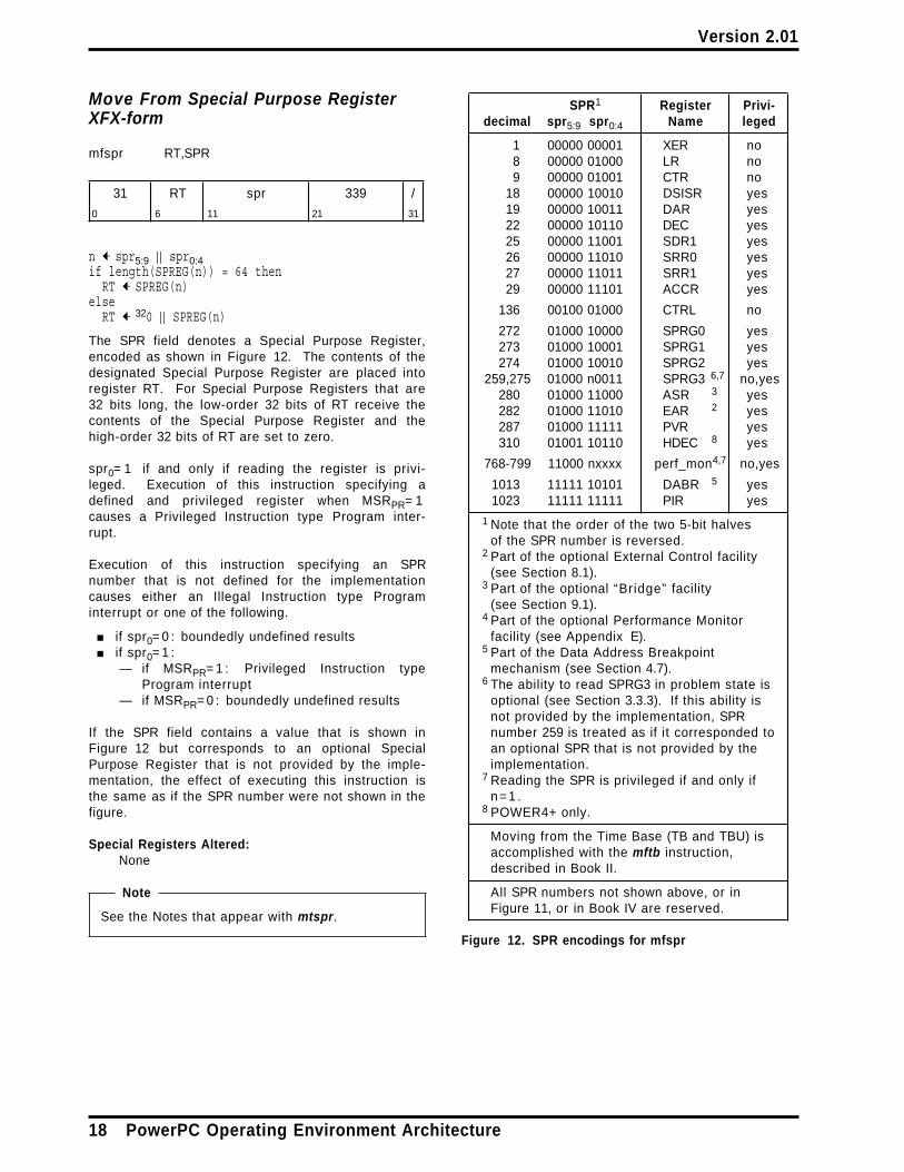
Move From Special Purpose RegisterXFX-form
mfspr RT,SPR
31 RT spr 339 /
0 6 11 21 31
n ← spr5:9 | | spr0:4if length(SPREG(n)) = 64 then
RT ← SPREG(n)else
RT ← 320 | | SPREG(n)
The SPR field denotes a Special Purpose Register,encoded as shown in Figure 12. The contents of thedesignated Special Purpose Register are placed intoregister RT. For Special Purpose Registers that are32 bits long, the low-order 32 bits of RT receive thecontents of the Special Purpose Register and thehigh-order 32 bits of RT are set to zero.
spr0= 1 if and only if reading the register is privi-leged. Execution of this instruction specifying adefined and privileged register when MSRPR= 1causes a Privileged Instruction type Program inter-rupt.
Execution of this instruction specifying an SPRnumber that is not defined for the implementationcauses either an Illegal Instruction type Programinterrupt or one of the following.
■ if spr0= 0 : boundedly undefined results■ if spr0= 1 :
— if MSRPR= 1 : Privileged Instruction typeProgram interrupt
— if MSRPR= 0 : boundedly undefined results
If the SPR field contains a value that is shown inFigure 12 but corresponds to an optional SpecialPurpose Register that is not provided by the imple-mentation, the effect of executing this instruction isthe same as if the SPR number were not shown in thefigure.
Special Registers Altered:None
Note
See the Notes that appear with mtspr.
SPR1 Register Privi-decimal spr5:9 spr0:4 Name leged
1 00000 00001 XER no8 00000 01000 LR no9 00000 01001 CTR no
18 00000 10010 DSISR yes19 00000 10011 DAR yes22 00000 10110 DEC yes25 00000 11001 SDR1 yes26 00000 11010 SRR0 yes27 00000 11011 SRR1 yes29 00000 11101 ACCR yes
136 00100 01000 CTRL no
272 01000 10000 SPRG0 yes273 01000 10001 SPRG1 yes274 01000 10010 SPRG2 yes
259,275 01000 n0011 SPRG3 6,7 no,yes280 01000 11000 ASR 3 yes282 01000 11010 EAR 2 yes287 01000 11111 PVR yes310 01001 10110 HDEC 8 yes
768-799 11000 nxxxx perf_mon4,7 no,yes
1013 11111 10101 DABR 5 yes1023 11111 11111 PIR yes
1 Note that the order of the two 5-bit halvesof the SPR number is reversed.
2 Part of the optional External Control facility(see Section 8.1).
3 Part of the optional “Bridge” facility(see Section 9.1).
4 Part of the optional Performance Monitorfacility (see Appendix E).
5 Part of the Data Address Breakpointmechanism (see Section 4.7).
6 The ability to read SPRG3 in problem state isoptional (see Section 3.3.3). If this ability isnot provided by the implementation, SPRnumber 259 is treated as if it corresponded toan optional SPR that is not provided by theimplementation.
7 Reading the SPR is privileged if and only ifn=1 .
8 POWER4+ only.
Moving from the Time Base (TB and TBU) isaccomplished with the mftb instruction,described in Book II.
All SPR numbers not shown above, or inFigure 11, or in Book IV are reserved.
Figure 12. SPR encodings for mfspr
18 PowerPC Operating Environment Architecture
Version 2.01
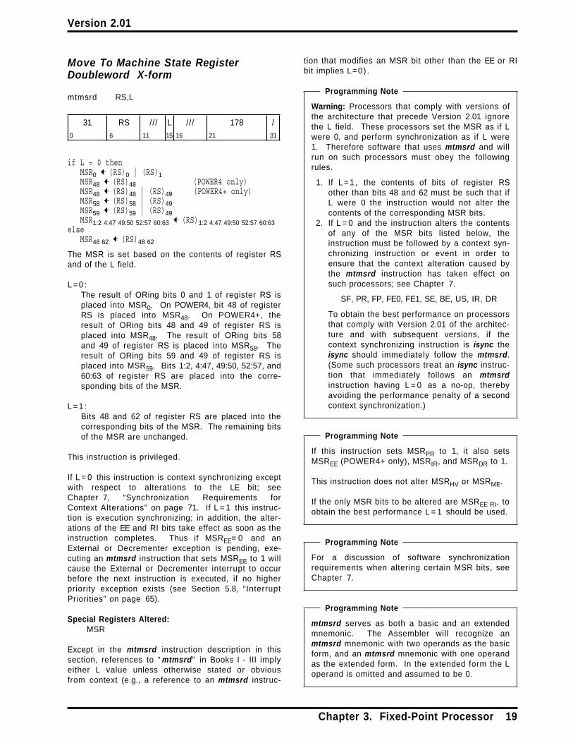
Move To Machine State RegisterDoubleword X-form
mtmsrd RS,L
31 RS /// L /// 178 /
0 6 11 15 16 21 31
if L = 0 thenMSR0 ← (RS)0 | (RS)1MSR48 ← (RS)48 (POWER4 only)MSR48 ← (RS)48 | (RS)49 (POWER4+ only)MSR58 ← (RS)58 | (RS)49MSR59 ← (RS)59 | (RS)49MSR1:2 4:47 49:50 52:57 60:63 ← (RS)1:2 4:47 49:50 52:57 60:63
elseMSR48 62 ← (RS)48 62
The MSR is set based on the contents of register RSand of the L field.
L=0 :The result of ORing bits 0 and 1 of register RS isplaced into MSR0. On POWER4, bit 48 of registerRS is placed into MSR48. On POWER4+, theresult of ORing bits 48 and 49 of register RS isplaced into MSR48. The result of ORing bits 58and 49 of register RS is placed into MSR58. Theresult of ORing bits 59 and 49 of register RS isplaced into MSR59. Bits 1:2, 4:47, 49:50, 52:57, and60:63 of register RS are placed into the corre-sponding bits of the MSR.
L=1 :Bits 48 and 62 of register RS are placed into thecorresponding bits of the MSR. The remaining bitsof the MSR are unchanged.
This instruction is privileged.
If L = 0 this instruction is context synchronizing exceptwith respect to alterations to the LE bit; seeChapter 7, “Synchronization Requirements forContext Alterations” on page 71. If L = 1 this instruc-tion is execution synchronizing; in addition, the alter-ations of the EE and RI bits take effect as soon as theinstruction completes. Thus if MSREE= 0 and anExternal or Decrementer exception is pending, exe-cuting an mtmsrd instruction that sets MSREE to 1 willcause the External or Decrementer interrupt to occurbefore the next instruction is executed, if no higherpriority exception exists (see Section 5.8, “InterruptPriorities” on page 65).
Special Registers Altered:MSR
Except in the mtmsrd instruction description in thissection, references to “ mtmsrd” in Books I - III implyeither L value unless otherwise stated or obviousfrom context (e.g., a reference to an mtmsrd instruc-
tion that modifies an MSR bit other than the EE or RIbit implies L=0) .
Programming Note
Warning: Processors that comply with versions ofthe architecture that precede Version 2.01 ignorethe L field. These processors set the MSR as if Lwere 0, and perform synchronization as if L were1. Therefore software that uses mtmsrd and willrun on such processors must obey the followingrules.
1. If L=1 , the contents of bits of register RSother than bits 48 and 62 must be such that ifL were 0 the instruction would not alter thecontents of the corresponding MSR bits.
2. If L = 0 and the instruction alters the contentsof any of the MSR bits listed below, theinstruction must be followed by a context syn-chronizing instruction or event in order toensure that the context alteration caused bythe mtmsrd instruction has taken effect onsuch processors; see Chapter 7.
SF, PR, FP, FE0, FE1, SE, BE, US, IR, DR
To obtain the best performance on processorsthat comply with Version 2.01 of the architec-ture and with subsequent versions, if thecontext synchronizing instruction is isync theisync should immediately follow the mtmsrd.(Some such processors treat an isync instruc-tion that immediately follows an mtmsrdinstruction having L = 0 as a no-op, therebyavoiding the performance penalty of a secondcontext synchronization.)
Programming Note
If this instruction sets MSRPR to 1, it also setsMSREE (POWER4+ only), MSRIR, and MSRDR to 1.
This instruction does not alter MSRHV or MSRME.
If the only MSR bits to be altered are MSREE RI, toobtain the best performance L = 1 should be used.
Programming Note
For a discussion of software synchronizationrequirements when altering certain MSR bits, seeChapter 7.
Programming Note
mtmsrd serves as both a basic and an extendedmnemonic. The Assembler will recognize anmtmsrd mnemonic with two operands as the basicform, and an mtmsrd mnemonic with one operandas the extended form. In the extended form the Loperand is omitted and assumed to be 0.
Chapter 3. Fixed-Point Processor 19

Version 2.01
Move From Machine State RegisterX-form
mfmsr RT
31 RT /// /// 83 /
0 6 11 16 21 31
RT ← MSR
The contents of the MSR are placed into register RT.
This instruction is privileged.
Special Registers Altered:None
20 PowerPC Operating Environment Architecture

Version 2.01
Chapter 4. Storage Control
4.1 Storage Addressing . . . . . . . . . 214.2 Storage Model . . . . . . . . . . . . 224.2.1 Storage Exceptions . . . . . . . . 224.2.2 Instruction Fetch . . . . . . . . . . 234.2.2.1 Implicit Branch . . . . . . . . . . 234.2.2.2 Address Wrapping Combined
with Changing MSR Bit SF . . . . . . . 234.2.3 Data Access . . . . . . . . . . . . . 234.2.4 Performing Operations
Out-of-Order . . . . . . . . . . . . . . . 234.2.4.1 Guarded Storage . . . . . . . . . 244.2.4.2 Out-of-Order Accesses to
Guarded Storage . . . . . . . . . . . . . 244.2.5 32-Bit Mode . . . . . . . . . . . . . 254.2.6 Real Addressing Mode . . . . . . 254.2.6.1 Offset Real Mode Address . . . 254.2.6.2 Storage Control Attributes for
Real Addressing Mode and for ImplicitStorage Accesses . . . . . . . . . . . . 26
4.2.7 Address Ranges Having DefinedUses . . . . . . . . . . . . . . . . . . . . 27
4.2.8 Invalid Real Address . . . . . . . 274.3 Address Translation Overview . . . 284.4 Virtual Address Generation . . . . 284.4.1 Segment Lookaside Buffer (SLB) 294.4.2 SLB Search . . . . . . . . . . . . . 294.5 Virtual to Real Translation . . . . . 30
4.5.1 Page Table . . . . . . . . . . . . . 314.5.2 Storage Description Register 1 . 324.5.3 Page Table Search . . . . . . . . . 334.6 Data Address Compare . . . . . . . 344.7 Data Address Breakpoint . . . . . . 354.8 Storage Control Bits . . . . . . . . . 354.8.1 Storage Control Bit Restrictions . 364.8.2 Altering the Storage Control Bits 364.9 Reference and Change Recording 374.10 Storage Protection . . . . . . . . . 394.10.1 Storage Protection, Address
Translation Enabled . . . . . . . . . . . 394.10.2 Storage Protection, Address
Translation Disabled . . . . . . . . . . 394.11 Storage Control Instructions . . . 404.11.1 Cache Management Instructions 404.11.2 Synchronize Instruction . . . . . 404.11.3 Lookaside Buffer Management . 404.11.3.1 SLB Management Instructions 414.11.3.2 TLB Management Instructions
(Optional) . . . . . . . . . . . . . . . . . 454.12 Page Table Update
Synchronization Requirements . . . . 484.12.1 Page Table Updates . . . . . . . 484.12.1.1 Adding a Page Table Entry . . 504.12.1.2 Modifying a Page Table Entry 504.12.1.3 Deleting a Page Table Entry . 50
4.1 Storage Addressing
A program references storage using the effectiveaddress computed by the processor when it executesa Load, Store, Branch, or Cache Management instruc-tion, or when it fetches the next sequential instruction.The effective address is translated to a real addressaccording to procedures described in Section 4.3,“Address Translation Overview” on page 28 and fol-
lowing sections. The real address is what is pre-sented to the storage subsystem. See Figure 13 onpage 28.
For a complete discussion of storage addressing andeffective address calculation, see the section entitled“Storage Addressing” in Book I, PowerPC UserInstruction Set Architecture.
Chapter 4. Storage Control 21

Version 2.01
Storage Control Overview
■ Real address space size is 2m bytes, m≤ 62; seeNote 1.
■ Real page size is 212 bytes (4 KB).
■ Effective address space size is 264 bytes.
■ An effective address is translated to a virtualaddress via the Segment Lookaside Buffer (SLB).
— Virtual address space size is 2n bytes,65≤ n≤ 80; see Note 2.
— Segment size is 228 bytes (256 MB).— Number of virtual segments is 2n− 28; see
Note 2.— Virtual page size is 2p bytes, 12≤ p≤ 28; two
sizes are supported simultaneously, 4 KB(p=12) and a larger size; see Note 3.
■ A virtual address is translated to a real addressvia the Page Table.
Notes:
1. The value of m is implementation-dependent(subject to the maximum given above). Whenused to address storage, the high-order 62− mbits of the “62-bit” real address must be zeros.
2. The value of n is implementation-dependent(subject to the range given above). In referencesto 80-bit virtual addresses elsewhere in this Book,the high-order 80− n bits of the “80-bit” virtualaddress are assumed to be zeros.
3. The value of p for the larger virtual page size isimplementation-dependent (subject to the rangegiven above).
4.2 Storage Model
The storage model provides the following features.
1. The architecture allows the storage implementa-tions to take advantage of the performance bene-fits of weak ordering of storage accesses betweenprocessors or between processors and I/Odevices.
2. In general, storage accesses appear to be per-formed in program order with respect to the
processor performing them but may be performedin different orders with respect to otherprocessors and mechanisms. Exceptions to thisrule are stated in the appropriate sections.
3. The architecture provides instructions that allowthe programmer to ensure a consistent andordered storage state.
dcbf lwarxdcbst stdcx.eieio stwcx.icbi Synchronizeisync tlbsyncldarx
4. Storage consistency between processors, andbetween a processor and an I/O device, is con-trolled by software using the “WIM” storagecontrol bits (see Section 4.8). These bits allowsoftware to control whether a given storagelocation has any of the following attributes.
■ Write Through Required (W)■ Caching Inhibited (I)■ Memory Coherence Required (M)
4.2.1 Storage Exceptions
A storage exception is an exception that causes anInstruction Storage interrupt, an Instruction Segmentinterrupt, a Data Storage interrupt, a Data Segmentinterrupt, or an Alignment interrupt. Attempting tofetch or execute an instruction causes a storageexception if certain conditions apply. Such conditionsinclude the following.
■ The appropriate relocate bit in the MSR is set to1 and the effective address cannot be translatedto a real address.
■ The access is not permitted by the storage pro-tection mechanism.
■ The access causes a Data Address Comparematch or a Data Address Breakpoint match.
In certain cases a storage exception may result in the“restart” of (re-execution of at least part of) a Load orStore instruction. See the section entitled “InstructionRestart” in Book II, PowerPC Virtual EnvironmentArchitecture, and Section 5.6, “Partially ExecutedInstructions” on page 63 in this Book.
22 PowerPC Operating Environment Architecture

Version 2.01
4.2.2 Instruction Fetch
Instructions are fetched under control of MSRIR.
MSR IR= 0
The effective address of the instruction is inter-preted as described in Section 4.2.6, “RealAddressing Mode” on page 25.
MSR IR= 1
The effective address of the instruction is trans-lated by the Address Translation mechanism. (If itcannot be translated, a storage exception occurs.)
4.2.2.1 Implicit Branch
Explicitly altering certain MSR bits (using mtmsr[ d]),or explicitly altering SLB entries, Page Table entries,or certain System Registers, may have the side effectof changing the addresses, effective or real, fromwhich the current instruction stream is being fetched.This side effect is called an implicit branch. Forexample, an mtmsrd instruction that changes thevalue of MSRSF may change the effective addressesfrom which the current instruction stream is beingfetched. The MSR bits and System Registers forwhich alteration can cause an implicit branch are indi-cated as such in Chapter 7, “SynchronizationRequirements for Context Alterations” on page 71.Implicit branches are not supported by the PowerPCArchitecture. If an implicit branch occurs, the resultsare boundedly undefined.
4.2.2.2 Address Wrapping Combinedwith Changing MSR Bit SF
If an mtmsrd instruction at address 232 − 4 is exe-cuted and changes the state of the SF bit, the effec-tive address of the next sequential instruction isundefined.
Programming Note
In the case described in the preceding paragraph,if an interrupt occurs immediately after themtmsrd instruction is executed, the contents ofSRR0 are undefined.
4.2.3 Data Access
Data accesses are controlled by MSRDR.
MSRDR= 0
The effective address of the data is interpreted asdescribed in Section 4.2.6, “Real AddressingMode” on page 25.
MSRDR= 1
The effective address of the data is translated bythe Address Translation mechanism. (If it cannotbe translated, a storage exception occurs.)
4.2.4 Performing OperationsOut-of-Order
An operation is said to be performed “ in-order” if, atthe time that it is performed, it is known to berequired by the sequential execution model. An oper-ation is said to be performed “out-of-order” if, at thetime that it is performed, it is not known to berequired by the sequential execution model. Oper-ations are performed out-of-order by the processor onthe expectation that the results will be needed by aninstruction that will be required by the sequential exe-cution model. Whether the results are really neededis contingent on everything that might divert thecontrol flow away from the instruction, such asBranch, Trap, System Call, and rfid instructions, andinterrupts, and on everything that might change thecontext in which the instruction is executed.
Typically, the processor performs operations out-of-order when it has resources that would otherwise beidle, so the operation incurs little or no cost. If subse-quent events such as branches or interrupts indicatethat the operation would not have been performed inthe sequential execution model, the processor aban-dons any results of the operation (except as describedbelow).
In the remainder of this section, including its sub-sections, “ Load instruction” includes the Cache Man-agement and other instructions that are stated in theinstruction descriptions to be “treated as a Load” , andsimilarly for “ Store instruction”.
A data access that is performed out-of-order may cor-respond to an arbitrary Load or Store instruction (e.g.,a Load or Store instruction that is not in the instruc-tion stream being executed). Similarly, an instructionfetch that is performed out-of-order may be for anarbitrary instruction (e.g., the aligned word at an arbi-trary location in instruction storage).
Most operations can be performed out-of-order, aslong as the machine appears to follow the sequentialexecution model. Certain out-of-order operations arerestricted, as follows.
Chapter 4. Storage Control 23
Version 2.01
■ Stores
Stores are not performed out-of-order (even if theStore instructions that caused them were exe-cuted out-of-order). Moreover, address trans-lations associated with instructions preceding thecorresponding Store instruction are not per-formed again after the store has been performed.
Programming Note
The fact that address translations associatedwith preceding instructions are not performedagain after the store has been performedpermits Page Table Entries to be updatedwithout a preceding context synchronizingoperation; see Section 4.12, “Page TableUpdate Synchronization Requirements” onpage 48. (These address translations musthave been performed before the store wasdetermined to be required by the sequentialexecution model, because they might havecaused an exception.)
■ Accessing Guarded Storage
The restrictions for this case are given in Section4.2.4.2.
The only permitted side effects of performing an oper-ation out-of-order are the following.
■ A Machine Check or Checkstop that could becaused by in-order execution may occur out-of-order, except as described in Section 8.2 if theoptional Real Mode Storage Control facility isimplemented.
■ Reference and Change bits may be set asdescribed in Section 4.9, “Reference and ChangeRecording” on page 37.
■ Non-Guarded storage locations that could befetched into a cache by in-order fetching or exe-cution of an arbitrary instruction may be fetchedout-of-order into that cache.
4.2.4.1 Guarded Storage
Storage is said to be “well-behaved” if the corre-sponding real storage exists and is not defective, andif the effects of a single access to it are indistinguish-able from the effects of multiple identical accesses toit. Data and instructions can be fetched out-of-orderfrom well-behaved storage without causing undesiredside effects.
Storage is said to be Guarded if either of the followingconditions is satisfied.
■ MSR bit IR or DR is 1 for instruction fetches ordata accesses respectively, and the G bit is 1 inthe relevant Page Table Entry.
■ MSR bit IR or DR is 0 for instruction fetches ordata accesses respectively, MSRHV= 1 , and theoptional Real Mode Storage Control facility (see
Section 8.2) is not implemented. In this case allof storage is Guarded for the correspondingaccesses.
In general, storage that is not well-behaved should beGuarded. Because such storage may represent acontrol register on an I/O device or may includelocations that do not exist, an out-of-order access tosuch storage may cause an I/O device to performunintended operations or may result in a MachineCheck.
The following rules apply to in-order execution ofLoad and Store instructions for which the first byte ofthe storage operand is in storage that is both CachingInhibited and Guarded.
■ Load or Store instruction that causes an atomicaccess
If any portion of the storage operand has beenaccessed and an External, Decrementer, orImprecise mode Floating-Point Enabled exceptionis pending, the instruction completes before theinterrupt occurs.
■ Load or Store instruction that causes an Align-ment exception, or that causes a Data Storageexception for reasons other than Data AddressCompare match or Data Address Breakpointmatch
The portion of the storage operand that is inCaching Inhibited and Guarded storage is notaccessed.
(The corresponding rules for instructions thatcause a Data Address Compare match or DataAddress Breakpoint match are given in Sections4.6 and 4.7 respectively.)
4.2.4.2 Out-of-Order Accesses toGuarded Storage
In general, Guarded storage is not accessed out-of-order. The only exceptions to this rule are the fol-lowing.
Load Instruction
If a copy of any byte of the storage operand is in acache then that byte may be accessed in the cache orin main storage.
Instruction Fetch
If MSRIR= 0 then an instruction may be fetched if anyof the following conditions are met.
1. The instruction is in a cache. In this case it maybe fetched from the cache or from main storage.
2. The instruction is in a real page from which aninstruction has previously been fetched, exceptthat if that previous fetch was based on condition1 then the previously fetched instruction musthave been in the instruction cache.
24 PowerPC Operating Environment Architecture

Version 2.01
3. The instruction is in the same real page as aninstruction that is required by the sequential exe-cution model, or is in the real page immediatelyfollowing such a page.
Programming Note
Software should ensure that only well-behavedstorage is copied into a cache, either byaccessing as Caching Inhibited (and Guarded) allstorage that may not be well-behaved, or byaccessing such storage as not Caching Inhibited(but Guarded) and referring only to cache blocksthat are well-behaved.
If a real page contains instructions that will beexecuted when MSRIR= 0 and MSRHV= 1 , soft-ware should ensure that this real page and thenext real page contain only well-behaved storage(or, if the optional Real Mode Storage Controlfacility is implemented, that this real page is notGuarded).
4.2.5 32-Bit Mode
The computation of the 64-bit effective address isindependent of whether the processor is in 32-bitmode or 64-bit mode. In 32-bit mode (MSRSF=0) , thehigh-order 32 bits of the 64-bit effective address aretreated as zeros for the purpose of addressingstorage. This applies to both data accesses andinstruction fetches. It applies independent of whetheraddress translation is enabled or disabled. This trun-cation of the effective address is the only respect inwhich storage accesses in 32-bit mode differ fromthose in 64-bit mode.
Programming Note
Treating the high-order 32 bits of the effectiveaddress as zeros effectively truncates the 64-biteffective address to a 32-bit effective addresssuch as would have been generated on a 32-bitimplementation of the PowerPC Architecture.Thus, for example, the ESID in 32-bit mode is thehigh-order four bits of this truncated effectiveaddress; the ESID thus lies in the range 0-15.When address translation is enabled, these fourbits would select a Segment Register on a 32-bitimplementation of the PowerPC Architecture. TheSLB entries that translate these 16 ESIDs can beused to emulate these Segment Registers.
4.2.6 Real Addressing Mode
A storage access is said to be performed in “realaddressing mode” if the access is an instruction fetchand instruction address translation is disabled(MSRIR=0) , or if the access is a data access and dataaddress translation is disabled (MSRDR=0) . Storageaccesses in real addressing mode are performed in amanner that depends on the contents of MSRHV,LPES/LPES1, and the RMLR and RMOR (see Section1.7, “Logical Partitioning (LPAR)” on page 4), asdescribed below. In all cases, bits 0:1 of the effectiveaddress are ignored and, on implementations thatsupport a real address size of only m bits, m< 62, bits2:63− m of the effective address may be ignored.
■ If MSRHV= 1 , bits 2:63 of the effective addressare used as the real address for the access.
■ If MSRHV= 0 and LPES/LPES1= 0 the accesscauses a storage exception as described inSection 4.10.2, “Storage Protection, AddressTranslation Disabled” on page 39.
■ If MSRHV= 0 and LPES/LPES1= 1 the Offset RealMode Address mechanism, described in Section4.2.6.1, controls the access.
4.2.6.1 Offset Real Mode Address
If MSRHV= 0 and LPES/LPES1= 1 , the access is con-trolled by the contents of the Real Mode Limit Reg-ister and Real Mode Offset Register, as follows.
Real Mode Limit Register (RMLR)
If bits 2:63 of effective address for the access aregreater than or equal to the value (limit) representedby the contents of the RMLR, the access causes astorage exception (see Section 4.10.2). The RMLRsupports effective address limits that are powers of 2.The number and values of the limits supported areimplementation-dependent.
Real Mode Offset Register (RMOR)
If the access is permitted by the RMLR, the effectiveaddress for the access is ORed with the offset repres-ented by the contents of the RMOR and the low-orderm bits of the result are used as the real address forthe access. The number and values of the offsetssupported are implementation-dependent.
Chapter 4. Storage Control 25

Version 2.01
Programming Note
The offset specified by the RMOR should be anon-zero multiple of the limit specified by theRMLR. If these registers are set thus, ORing theeffective address with the offset produces a resultthat is equivalent to adding the effective addressand the offset. (The offset must not be zero,because real page 0 contains the fixed interruptvectors and real pages 1 and 2 may be used forimplementation-specific purposes; see Section4.2.7, “Address Ranges Having Defined Uses” onpage 27.)
4.2.6.2 Storage Control Attributes forReal Addressing Mode and for ImplicitStorage Accesses
Data accesses and instruction fetches in realaddressing mode when the processor is in hypervisorstate are performed as though all of storage had thefollowing storage control attributes, except as modi-fied by the optional Real Mode Storage Control facility(see Section 8.2) if that facility is implemented. (Thestorage control attributes are defined in Book II,PowerPC Virtual Environment Architecture .)
■ not Write Through Required■ not Caching Inhibited, for instruction fetches■ not Caching Inhibited, for data accesses if the
Real Mode Caching Inhibited bit is set to 0;Caching Inhibited, for data accesses if the RealMode Caching Inhibited bit is set to 1
■ Memory Coherence Required, for data accesses■ Guarded
Storage accesses in real addressing mode when theprocessor is not in hypervisor state are performed asthough all of storage had the following storage controlattributes. (Such accesses use the Offset Real ModeAddress mechanism.)
■ not Write Through Required■ not Caching Inhibited■ Memory Coherence Required, for data accesses■ not Guarded
Implicit accesses to the Page Table by the processorin performing address translation and in recordingreference and change information are performed asthough the storage occupied by the Page Table hadthe following storage control attributes.
■ not Write Through Required■ not Caching Inhibited■ Memory Coherence Required■ not Guarded
The definition of “performed” given in Book II appliesalso to these implicit accesses; accesses for per-forming address translation are considered to beloads in this respect, and accesses for recording ref-erence and change information are considered to bestores. These implicit accesses are ordered by theptesync instruction as described in Section 4.11.2 onpage 40.
Software must ensure that any data storage locationthat is accessed with the Real Mode Caching Inhibitedbit set to 1 is not in the caches.
Software must ensure that the Real Mode CachingInhibited bit contains 0 whenever data address trans-lation is enabled and whenever the processor is not inhypervisor state.
26 PowerPC Operating Environment Architecture

Version 2.01
Programming Note
Because storage accesses in real addressingmode do not use the SLB or the Page Table,accesses in this mode bypass all checking andrecording of information contained therein (e.g.,storage protection checks that use informationcontained therein are not performed, and refer-ence and change information is not recorded).
Because in real addressing mode all storage isnot Caching Inhibited (unless the Real ModeCaching Inhibited bit is 1), software should notmap a Caching Inhibited virtual page to storagethat is treated as non-Guarded in real addressingmode. Doing so could permit storage locations inthe virtual page to be copied into the cache,which could lead to violations of the requirementgiven in Section 4.8.2 for changing the value ofthe I bit. See also Section 8.2 on page 77.
The Real Mode Caching Inhibited bit can be usedto permit a control register on an I/O device to beaccessed without permitting the correspondingstorage location to be copied into the caches.The bit should normally contain 0. Softwarewould set the bit to 1 just before accessing thecontrol register, access the control register asneeded, and then set the bit back to 0.
4.2.7 Address Ranges HavingDefined Uses
The address ranges described below have uses thatare defined by the architecture.
■ Fixed interrupt vectors
Except for the first 256 bytes, which are reservedfor software use, the real page beginning at realaddress 0x0000_0000_0000_0000 is either usedfor interrupt vectors or reserved for future inter-rupt vectors.
■ Implementation-specific use
The two contiguous real pages beginning at realaddress 0x0000_0000_0000_1000 are reserved forimplementation-specific purposes.
■ Offset Real Mode interrupt vectors
The real page beginning at the real address spec-ified by the RMOR is used similarly to the pagefor the fixed interrupt vectors.
■ Page Table
A contiguous sequence of real pages beginning atthe real address specified by SDR1 contains thePage Table.
4.2.8 Invalid Real Address
A storage access (including an access that is per-formed out-of-order; see Section 4.2.4) may cause aMachine Check if the accessed storage location con-tains an uncorrectable error or does not exist. In thelatter case the Checkstop state may be entered. SeeSection 5.5.2, “Machine Check Interrupt” on page 55.
Programming Note
Hypervisor software must ensure that a storageaccess by a program in one partition will notcause a Checkstop or other system-wide eventthat could affect the integrity of other partitions(see Section 1.7, “Logical Partitioning (LPAR)” onpage 4). For example, such an event could occurif a real address placed in a Page Table Entry ormade accessible to a partition using the OffsetReal Mode Address mechanism (see Section4.2.6.1) does not exist.
Chapter 4. Storage Control 27

Version 2.01
4.3 Address TranslationOverview
The effective address (EA) is the address generatedby the processor for an instruction fetch or for a dataaccess. If address translation is enabled (MSRIR= 1or MSRDR= 1 as appropriate), this address is passedto the Address Translation mechanism, whichattempts to convert the address to a real addresswhich is then used to access storage.
The first step in address translation is to convert theeffective address to a virtual address (VA), asdescribed in Section 4.4. The second step, conversionof the virtual address to a real address (RA), isdescribed in Section 4.5.
If the effective address cannot be translated, astorage exception (see Section 4.2.1) occurs.
Figure 13 gives an overview of the address trans-lation process.
ÚÄÄÄÄÄÄÄÄÄÄÄÄÄÄÄÄÄÄÄÄÄÄÄÄÄ¿³ Effective Address ³ÀÄÄÄÄÄÄÄÄÄÄÄÄÂÄÄÄÄÄÄÄÄÄÄÄÄÙ
³↓
ÚÄÄÄÄÄÄÄÄÄÄÄÄÄÄÄÄÄÄÄÄÄÄÄÄÄ¿³ ³³ Lookup in ³³ SLB ³³ ³ÀÄÄÄÄÄÄÄÄÄÄÄÄÂÄÄÄÄÄÄÄÄÄÄÄÄÙ
³↓
ÚÄÄÄÄÄÄÄÄÄÄÄÄÄÄÄÄÄÄÄÄÄÄÄÄÄ¿³ Virtual Address ³ÀÄÄÄÄÄÄÄÄÄÄÄÄÂÄÄÄÄÄÄÄÄÄÄÄÄÙ
³↓
ÚÄÄÄÄÄÄÄÄÄÄÄÄÄÄÄÄÄÄÄÄÄÄÄÄÄ¿³ ³³ Lookup in ³³ Page Table ³³ ³ÀÄÄÄÄÄÄÄÄÄÄÄÄÂÄÄÄÄÄÄÄÄÄÄÄÄÙ
³↓
ÚÄÄÄÄÄÄÄÄÄÄÄÄÄÄÄÄÄÄÄÄÄÄÄÄÄ¿³ Real Address ³ÀÄÄÄÄÄÄÄÄÄÄÄÄÄÄÄÄÄÄÄÄÄÄÄÄÄÙ
Figure 13. Address translation overview
4.4 Virtual Address Generation
Conversion of a 64-bit effective address to a virtualaddress is done by searching the Segment LookasideBuffer (SLB) as shown in Figure 14.
64-bit Effective Address
ÚÄÄÄÄÄÄÄÄÄ36ÄÂÄÄÄÄÄ28-pÄÂÄÄÄÄÄÄpÄÄ¿³ ESID ³ Page ³ Byte ³ÀÄÄÄÄÄÄÄÄÄÄÄÄÁÄÄÄÄÄÄÄÄÄÄÁÄÄÄÄÄÄÄÄÄÙ
0 35 36 63-p 64-p 63ÀÄÄÄÄÄÂÄÄÄÄÙ ÀÄÄÄÄÂÄÄÄÙ ÀÄÄÄÄÄÂÄÙ
³ ³ ³ÚÄÄÄÄÄÄÄÄÄÄÄÄÄÄÄÄÙ ³ ³³ ³ ³³ Segment Lookaside ³ ³³ Buffer (SLB) ³ ³↓ ³ ³
ÚÄÄÄÄÄÄÄÄÄÂÄÂÄÄÄÄÄÄÄÄÄÂÄÄÄÄÄÄÄ¿ ³ ³SLBE0 ³ ESID ³V³ VSID ³KsKpNLC³ ³ ³
ÃÄÄÄÄÄÄÄÄÄÅÄÅÄÄÄÄÄÄÄÄÄÅÄÄÄÄÄÄÄ́ ³ ³³ ³ ³ ³ ³ ³ ³³ ³ ³ ³ ³ ³ ³= = = = = ³ ³³ ³ ³ ³ ³ ³ ³³ ³ ³ ³ ³ ³ ³ÃÄÄÄÄÄÄÄÄÄÅÄÅÄÄÄÄÄÄÄÄÄÅÄÄÄÄÄÄÄ́ ³ ³
SLBEn ³ ³ ³ ³ ³ ³ ³ÀÄÄÄÄÄÄÄÄÄÁÄÁÄÄÄÄÄÄÄÄÄÁÄÄÄÄÄÄÄÙ ³ ³0 35 37 88 89 93 ³ ³
ÀÄÄÄÄÄÄÂÄÄÙ ³ ³³ ³ ³↓ ↓ ↓
ÚÄÄÄÄÄÄÄÄÄÄÄÄÄ52ÄÂÄÄÄÄÄ28-pÄÂÄÄÄÄÄÄpÄ¿³ VSID ³ Page ³ Byte ³ÀÄÄÄÄÄÄÄÄÄÄÄÄÄÄÄÄÁÄÄÄÄÄÄÄÄÄÄÁÄÄÄÄÄÄÄÄÙIÄVirtual Page Number (VPN)ÄH
80-bit Virtual Address
Figure 14. Translation of 64-bit effective address to 80-bitvirtual address
28 PowerPC Operating Environment Architecture

Version 2.01
4.4.1 Segment Lookaside Buffer(SLB)
The Segment Lookaside Buffer (SLB) specifies themapping between Effective Segment IDs (ESIDs) andVirtual Segment IDs (VSIDs). The number of SLBentries is implementation-dependent, except that allimplementations provide at least 32 entries.
The contents of the SLB are managed by software,using the instructions described in Section 4.11.3.1,“SLB Management Instructions” on page 41. SeeChapter 7, “Synchronization Requirements forContext Alterations” on page 71 for the rules thatsoftware must follow when updating the SLB.
SLB Entry
Each SLB entry (SLBE) maps one ESID to one VSID.Figure 15 shows the layout of an SLB entry.
ESID V VSID KsKpNLC
0 35 37 89 93
Bit(s) Name Description0:35 ESID Effective Segment ID
36 V Entry valid (V=1) orinvalid (V=0)
37:88 VSID Virtual Segment ID89 Ks Supervisor (privileged) state
storage key90 Kp Problem state storage key91 N No-execute segment if N = 192 L Virtual pages are large (L=1)
or 4 KB (L=0)93 C Class
Figure 15. SLB Entry
On implementations that support a virtual addresssize of only n bits, n< 80, bits 0:79− n of the VSID fieldare treated as reserved bits, and software must setthem to zeros.
A No-execute segment (N=1) contains data thatshould not be executed.
The L bit selects between two virtual page sizes, 4 KB(p=12) and “ large”. The large page size is an imple-mentation-dependent value that is a power of 2 and isin the range 8 KB : 256 MB (13≤ p≤ 28). Some imple-mentations may provide a means by which softwarecan select the large page size from a set of severalimplementation-dependent sizes during system initial-ization.
If “ large page” is used in reference to real storage, itmeans the sequence of contiguous real (4 KB) pagesto which a large virtual page is mapped.
The Class field is used in conjunction with the slbieinstruction (see Section 4.11.3.1).
Software must ensure that the SLB contains at mostone entry that translates a given effective address(i.e., that a given ESID is contained in no more thanone SLB entry).
Programming Note
Because the virtual page size is used both insearching the Page Table and in forming the realaddress using the matching Page Table Entry(PTE) (see Section 4.5, “Virtual to RealTranslation” on page 30), and PTEs contain noindication of the virtual page size, the virtual pagesize must be the same for all address translationsthat use a given VSID value. This has the fol-lowing consequences, which apply collectively toall processors that use the same Page Table.
■ The value of the L bit must be the same in allSLB entries that contain a given VSID value.
■ Before changing the value of the L bit in anSLB entry, software must invalidate all SLBentries, TLB entries, and PTEs that containthe corresponding VSID value.
4.4.2 SLB Search
When the hardware searches the SLB, all entries aretested for a match with the EA. For a match to exist,the following must be true:
■ SLBEV = 1■ SLBEESID = EA0:35
If the SLB search succeeds, the virtual address (VA)is formed by concatenating the VSID from thematching SLB entry with bits 36:63 of the EA.
The Virtual Page Number (VPN) is bits 0:79− p of thevirtual address.
If the SLB search fails, a segment fault occurs. This isan Instruction Segment exception or a Data Segmentexception, depending on whether the effectiveaddress is for an instruction fetch or for a dataaccess.
Chapter 4. Storage Control 29

Version 2.01
4.5 Virtual to Real Translation
Conversion of an 80-bit virtual address to a real address is done by searching the Page Table as shown inFigure 16.
ÚÄÄÄÄÄÄÄÄÄÄÄÄÄÄÄÄÄÄÄÄÄÄÄÄÄÄÄÄÄÄÄÄÄÄÄÄÄÄÄÄÄÄÄÄÄÄÄÄÄÄÄÄÄÄÄÄÄÄÄ80-pÄÂÄÄÄÄÄÄÄÄÄpÄ¿80-bit Virtual Address ³ Virtual Page Number (VPN) ³ Byte ³
ÀÄÄÄÄÄÄÄÄÄÄÄÄÄÄÄÄÄÄÄÄÄÄÄÄÄÄÄÄÄÄÄÄÄÄÄÄÄÄÄÄÄÄÄÄÄÄÄÄÄÄÄÄÄÄÄÄÄÄÄÄÄÄÄÄÁÄÄÄÄÄÄÄÄÄÄÄÙ0 13 51 52 79-p 80-p 79
ÀÄÄÄÄÄÄÄÄÄÂÄÄÄÄÄÄÄÄÄÄÄÄÄÄÄÄÄÄÄÄÄÄÄÄÄÄÙ ÀÄÄÄÄÄÄÂÄÄÄÄÄÄÙ ÀÄÄÄÄÂÄÄÄÄÙ³ ³ ³³ ³ ÀÄÄÄÄÄÄÄÄÄÄÄÄÄÄÄÄÄÄÄÄÄ¿
HTABORG HTABSIZE ³ ↓ ³ÚÄ2ÂÄÄÄÄÄÄÄÄÄÄÄÄÄÄÄÄÄÄÄÄÄÄÄÄÄÄÄÄÄÄÄ44ÄÂÄÄÄÄÄÄÄÄ13ÄÂÄÄÄÄÄÄÄÄÄÄÄ5Ä¿ ³ ÚÄÄÄÄÄÄÄÄÄÄÄÄÄÄÄ11+pÄÂÄÄÄÄÄÄÄÄÄÄ28-pÄ¿ ³
SDR1 ³//³ xxx.................xx000.....00 ³ /// ³ ³ ³ ³ 0s ³ ³ ³ÀÄÄÁÄÄÄÄÄÄÄÄÄÄÄÄÄÄÄÄÄÄÄÄÄÄÄÄÄÄÄÄÄÄÄÄÄÄÁÄÄÄÄÄÄÄÄÄÄÄÁÄÄÄÄÄÄÄÄÄÄÄÄÄÙ ³ ÀÄÄÄÄÄÄÄÄÄÄÄÄÄÄÄÄÄÄÄÄÁÄÄÄÄÄÄÄÄÄÄÄÄÄÄÄÙ ³0 2 17 18 45 59 63 ³ 0 38 ³
ÀÄÄÄÄÂÄÄÄÄÙ ÀÄÄÄÄÄÄÄÄÄÂÄÄÄÄÄÄÄÄÄÄÙ ÀÄÄÄÄÄÂÄÄÄÄÄÙ ³ ÀÄÄÄÄÄÄÄÄÄÄÄÄÄÄÄÄÂÄÄÄÄÄÄÄÄÄÄÄÄÄÄÄÄÄÙ ³³ ³ ³ ³ ³ ³³ ³ ³ ³ ÚÄÄÄÄÄÄÄÄÄÄÄÄÄÙ ³³ ³ ↓ ³ ³ ³³ ³ ÚÄÄÄÄÄÄÄÄÄ¿ ↓ ↓ ³³ ³ ³ ³ ÚÄÄÄÄÄÄÄÄÄÄÄÄÄÄÄÄÄÄÄ¿ ³³ ³ ³ DECODE ³ ³ ³ ³³ ³ ³ ³ ³ Hash Function ³ ³³ ³ ÀÄÄÄÄÂÄÄÄÄÙ ³ ³ ³³ ³ ³ ÀÄÄÄÄÄÄÄÄÄÂÄÄÄÄÄÄÄÄÄÙ ³³ ³ ³ ³ ³³ ³ Mask ↓ ↓ ³³ ³ ÚÄÄÄÄÄÄÄÄÄÄÄÄÄÄÄÄÄÄÄ28Ä¿ ÚÄÄÄÄÄÄÄÄÄÄÄÄÄÄÄÄÄÄÄÄÄÄÄÄÄÄÄÄÄÄÄÄÄ39Ä¿ ³³ ³ ³ 000.....00111.....11 ³ ³ ³ ³³ ³ ÀÄÄÄÄÄÄÄÄÄÄÄÄÄÄÄÄÄÄÄÄÄÄÙ ÀÄÄÄÄÄÄÄÄÄÄÄÄÄÄÄÄÄÄÄÄÄÄÄÄÄÄÄÄÄÄÄÄÄÄÄÄÙ ³³ ³ 0 27 0 27 28 38 ³³ ³ ÀÄÄÄÄÄÄÄÄÄÄÂÄÄÄÄÄÄÄÄÄÙ ÀÄÄÄÄÄÄÄÄÄÂÄÄÄÄÄÄÄÄÄÄÙ ÀÄÄÄÄÄÂÄÄÄÄÄÙ ³³ ³ ³ ³ ³ ³³ ³ ³ ÚÄÄÄÄÄÄÄÄÄÄÄÄÄÄÄÄÄÄÄÄÙ ³ ³³ ³ ³ ³ ³ ³³ ÀÄÄÄÄÄÄÄÄÄ¿ ↓ ↓ ³ ³³ ³ ÚÄÄÄÄÄÄÄÄÄ¿ ³ ³³ ³ ³ ³ ³ ³ÀÄÄÄÄÄÄÄ¿ ³ ³ AND ³ ³ ³
³ ³ ³ ³ ³ ³³ ³ ÀÄÄÄÄÂÄÄÄÄÙ ³ ³³ ³ ³ ³ ³³ ³ ÚÄÄÄÄÄÄÄÄÄÄÄÄÄÄÙ ³ ³³ ³ ³ ³ ³³ ³ ³ ÚÄÄÄÄÄÄÄÄÄÄÄÄÄÄÄÄÄÄÄÄÄÄÄÄÄÄÄÄÄÄÄÄÄÄÄÄÄÄÄÙ ³³ ³ ³ ³ ³³ ³ ³ ³ ³³ ↓ ↓ ³ ³³ ÚÄÄÄÄÄÄÄÄÄ¿ ³ Page Table ³³ ³ ³ ³ ³³ ³ OR ³ ³ ÄÄH| |IÄÄ 16 bytes ³³ ³ ³ ³ / ÚÄÄÄÄÄÄÂÄÄÄÄÄÄÂÄÄÄÄÄÄÂÄÄÄÄÄÄÂÄÄÄÄÄÄÂÄÄÄÄÄÄÂÄÄÄÄÄÄÂÄÄÄÄÄÄ¿ ³³ ÀÄÄÄÄÂÄÄÄÄÙ ³ / ³ PTE0 ³ ³ ³ ³ ³ ³ ³ PTE7 ³ PTEG0 ³³ ³ ³ / ÃÄÄÄÄÄÄÅÄÄÄÄÄÄÅÄÄÄÄÄÄÅÄÄÄÄÄÄÅÄÄÄÄÄÄÅÄÄÄÄÄÄÅÄÄÄÄÄÄÅÄÄÄÄÄÄ´ ³↓ ↓ ↓ / ³ ³ ³ ³ ³ ³ ³ ³ ³ ³
ÚÄÄÄÄÄÄÄÄÄÄÄÄÄÄ16ÄÂÄÄÄÄÄÄÄÄÄÄÄÄÄÄÄÄÄÄÄ28ÄÂÄÄÄÄÄÄÄÄÄÄ11ÄÂÄÄÄÄÄ7Ä¿ / ³ ³ ³ ³ ³ ³ ³ ³ ³ ³³ ³ ³ ³0000000³ = = = = = = = = = ³ÀÄÄÄÄÄÄÄÄÄÄÄÄÄÄÄÄÄÁÄÄÄÄÄÄÄÄÄÄÄÄÄÄÄÄÄÄÄÄÄÄÁÄÄÄÄÄÄÄÄÄÄÄÄÄÁÄÄÄÄÄÄÄÙ \ ³ ³ ³ ³ ³ ³ ³ ³ ³ ³
\ ³ ³ ³ ³ ³ ³ ³ ³ ³ ³62-bit Real Address of Page Table Entry Group \ ÃÄÄÄÄÄÄÅÄÄÄÄÄÄÅÄÄÄÄÄÄÅÄÄÄÄÄÄÅÄÄÄÄÄÄÅÄÄÄÄÄÄÅÄÄÄÄÄÄÅÄÄÄÄÄÄ´ ³
\ ³ ³ ³ ³ ³ ³ ³ ³ ³ PTEGn ³\ ÀÄÄÄÄÄÄÁÄÄÄÄÄÄÁÄÄÄÄÄÄÁÄÄÄÄÄÄÁÄÄÄÄÄÄÁÄÄÄÄÄÄÁÄÄÄÄÄÄÁÄÄÄÄÄÄÙ ³
³IÄÄÄÄÄÄÄÄÄÄÄÄÄÄÄÄÄÄÄÄÄÄ 128 bytes ÄÄÄÄÄÄÄÄÄÄÄÄÄÄÄÄÄÄÄÄÄÄH ³
³Page Table Entry (PTE) ³16 bytes ³
³ÚÄÄÄÄÄÄÄÄÄÄÄÄÄÄÄÄÄÄÄÄÄÄÄÄÄÄÄÄÄÄÄÄÄÄÄÄÄÄÄÄÄ57ÄÂÄÄÄÄÄÂÄÄÂÄÄÂÄÄ¿ÚÄÄÂÄÄÂÄÄÄÄÄÄÄÄÄÄÄÄÄÄÄÄÄÄÄÄÄÄÄÄÄÄÄÄ50ÄÂÄÄÄÄÂÄÄÂÄÄÂÄÄÂÄÄÄÄÄÄÂÄÄÂÄÄÄÄ¿ ³³ AVPN ³ SW ³/ ³H ³V ³³ /³ /³ Real Page Number (RPN) ³ // ³AC³R ³C ³ WIMG ³N ³ PP ³ ³ÀÄÄÄÄÄÄÄÄÄÄÄÄÄÄÄÄÄÄÄÄÄÄÄÄÄÄÄÄÄÄÄÄÄÄÄÄÄÄÄÄÄÄÄÄÁÄÄÄÄÄÁÄÄÁÄÄÁÄÄÙÀÄÄÁÄÄÁÄÄÄÄÄÄÄÄÄÄÄÄÄÄÄÄÄÄÄÄÄÄÄÄÄÄÄÄÄÄÄÁÄÄÄÄÁÄÄÁÄÄÁÄÄÁÄÄÄÄÄÄÁÄÄÁÄÄÄÄÙ ³0 56 60 62 63 0 1 2 63Äp 52 54 55 56 57 60 61 63 ³
ÀÄÄÄÄÄÄÄÄÄÄÂÄÄÄÄÄÄÄÄÄÄÄÄÄÄÄÄÙ ³³ ³ÀÄÄÄÄÄÄÄÄÄÄÄÄÄÄÄÄÄÄÄÄÄÄÄÄÄ¿ ³
³ ³↓ ↓
ÚÄÄÄÄÄÄÄÄÄÄÄÄÄÄÄÄÄÄÄÄÄÄÄÄÄÄÄÄÄÄÄÄÄÄÄÄÄ62-pÄÂÄÄÄÄÄÄÄÄÄpÄ¿62-bit Real Address ³ RPN ³ Byte ³
ÀÄÄÄÄÄÄÄÄÄÄÄÄÄÄÄÄÄÄÄÄÄÄÄÄÄÄÄÄÄÄÄÄÄÄÄÄÄÄÄÄÄÄÁÄÄÄÄÄÄÄÄÄÄÄÙ
Figure 16. Translation of 80-bit virtual address to 62-bit real address
30 PowerPC Operating Environment Architecture

Version 2.01
4.5.1 Page Table
The Hashed Page Table (HTAB) is a variable-sizeddata structure that specifies the mapping betweenVirtual Page Numbers and Real Page Numbers. TheHTAB's size must be a multiple of 4 KB, its startingaddress must be a multiple of its size, and it must belocated in storage having the storage control attri-butes that are used for implicit accesses to it (seeSection 4.2.6.2).
The HTAB contains Page Table Entry Groups (PTEGs).A PTEG contains 8 Page Table Entries (PTEs) of 16bytes each; each PTEG is thus 128 bytes long. PTEGsare entry points for searches of the Page Table.
See Section 4.12, “Page Table Update Synchroniza-tion Requirements” on page 48 for the rules that soft-ware must follow when updating the Page Table.
Programming Note
The Page Table must be treated as a hypervisorresource (see Section 1.7, “Logical Partitioning(LPAR)” on page 4), and therefore must be placedin real storage to which only the hypervisor haswrite access. Moreover, the contents of the PageTable must be such that non-hypervisor softwarecannot modify storage that contains hypervisorprograms or data. Finally, to protect againstincorrect use of the L bit of SLB entries by non-hypervisor software, real storage that is mappedby the Page Table must be allocated to partitionsin units each of which has a size that is a multipleof 2P bytes and is aligned at a 2P byte boundary,where 2P is the maximum large page size for anyprocessor in the system. (Incorrect use of the Lbit could cause the virtual address for a largevirtual page to be translated using a PTE that wascreated to translate a 4 KB virtual page. If 2P
were the maximum large page size for the parti-tion, instead of for the system, it might be neces-sary to change a processor's large page size aspart of reassigning the processor to a differentpartition.)
Page Table Entry
Each Page Table Entry (PTE) maps one VPN to oneRPN. Figure 17 shows the layout of a PTE.
0 56 60 62 63
AVPN SW / H V
/ / RPN // AC R C WIMG N PP
0 1 2 51 54 55 5657 60 61 62 63
Dword Bit(s) Name Description0 0:56 AVPN Abbreviated Virtual Page
Number57:60 SW Available for software use62 H Hash function identifier63 V Entry valid (V=1)
or invalid (V=0)1 2:51 RPN Real Page Number
54 AC Address Compare bit55 R Reference bit56 C Change bit57:60 WIMG Storage control bits61 N No-execute page if N = 162:63 PP Page protection bits
All other fields are reserved.
Figure 17. Page Table Entry
If p≤ 23, the Abbreviated Virtual Page Number (AVPN)field contains bits 0:56 of the VPN. Otherwise bits0:79− p of the AVPN field contain bits 0:79− p of theVPN, and bits 80− p:56 of the AVPN field must bezeros.
Programming Note
If p≤ 23, the AVPN field omits the low-order 23− pbits of the VPN. These bits are not needed in thePTE, because the low-order 11 bits of the VPN arealways used in selecting the PTEGs to besearched (see Section 4.5.3).
On implementations that support a virtual addresssize of only n bits, n< 80, bits 0:79− n of the AVPN fieldmust be zeros.
The RPN field contains the page number of the realpage that contains the first byte of the block of realstorage to which the virtual page is mapped. If p> 12,the low-order p− 12 bits of the RPN field (bits 64− p:51of doubleword 1 of the PTE) must be 0. On implemen-tations that support a real address size of only m bits,m< 62, bits 0:61− m of the RPN field must be zeros.
Programming Note
For a large virtual page, the high-order 62− p bitsof the RPN field (bits 0:61− p) comprise the largereal page number.
Chapter 4. Storage Control 31

Version 2.01
A No-execute page (N=1) contains data that shouldnot be executed.
Page Table Size
The number of entries in the Page Table directlyaffects performance because it influences the hit ratioin the Page Table and thus the rate of page faults. Ifthe table is too small, it is possible that not all thevirtual pages that actually have real pages assignedcan be mapped via the Page Table. This can happenif too many hash collisions occur and there are morethan 16 entries for the same primary/secondary pairof PTEGs. While this situation cannot be guaranteednot to occur for any size Page Table, making the PageTable larger than the minimum size (see Section4.5.2) will reduce the frequency of occurrence of suchcollisions.
Programming Note
If large pages are not used, it is recommendedthat the number of PTEGs in the Page Table be atleast half the number of real pages to beaccessed. For example, if the amount of realstorage to be accessed is 231 bytes (2 GB), thenwe have 231− 12= 2 19 real pages. The minimumrecommended Page Table size would be 218
PTEGs, or 225 bytes (32 MB).
4.5.2 Storage Description Register 1
The SDR1 register is shown in Figure 18.
// HTABORG /// HTABSIZE
0 2 45 59 63
Bits Name Description2:45 HTABORG Real address of Page Table59:63 HTABSIZE Encoded size of Page Table
All other fields are reserved.
Figure 18. SDR1
SDR1 is a hypervisor resource; see Section 1.7,“Logical Partitioning (LPAR)” on page 4.
The HTABORG field in SDR1 contains the high-order44 bits of the 62-bit real address of the Page Table.The Page Table is thus constrained to lie on a 218 byte(256 KB) boundary at a minimum. At least 11 bitsfrom the hash function (see Figure 16 on page 30)are used to index into the Page Table. The minimumsize Page Table is 256 KB (211 PTEGs of 128 byteseach).
The Page Table can be any size 2n bytes where18≤ n≤ 46. As the table size is increased, more bitsare used from the hash to index into the table and thevalue in HTABORG must have more of its low-orderbits equal to 0.
The HTABSIZE field in SDR1 contains an integergiving the number of bits (in addition to the minimumof 11 bits) from the hash that are used in the PageTable index. This number must not exceed 28.HTABSIZE is used to generate a mask of the form0b00...011...1, which is a string of 28 − HTABSIZE0-bits followed by a string of HTABSIZE 1-bits. The1-bits determine which additional bits (beyond theminimum of 11) from the hash are used in the index(see Figure 16 on page 30). The number of low-order0 bits in HTABORG must be greater than or equal tothe value in HTABSIZE.
On implementations that support a real address sizeof only m bits, m< 62, bits 0:61− m of the HTABORGfield are treated as reserved bits, and software mustset them to zeros.
32 PowerPC Operating Environment Architecture

Version 2.01
Programming Note
Let n equal the virtual address size (in bits) sup-ported by the implementation. If n< 67, softwareshould set the HTABSIZE field to a value thatdoes not exceed n− 39. Because the high-order80− n bits of the VSID are assumed to be zeros,the hash value used in the Page Table search willhave the high-order 67− n bits either all 0s(primary hash; see Section 4.5.3) or all 1s (sec-ondary hash). If HTABSIZE> n− 39, some of thesehash value bits will be used to index into the PageTable, with the result that certain PTEGs will notbe searched.
Example:
Suppose that the Page Table is 16,384 (214) 128-bytePTEGs, for a total size of 221 bytes (2 MB). A 14-bitindex is required. Eleven bits are provided from thehash to start with, so 3 additional bits from the hashmust be selected. Thus the value in HTABSIZE mustbe 3 and the value in HTABORG must have its low-order 3 bits (bits 43:45 of SDR1) equal to 0. Thismeans that the Page Table must begin on a 23 + 1 1 + 7
= 221 = 2 MB boundary.
4.5.3 Page Table Search
When the hardware searches the Page Table, theaccesses are performed as described in Section4.2.6.2, “Storage Control Attributes for RealAddressing Mode and for Implicit Storage Accesses”on page 26.
An outline of the HTAB search process is shown inFigure 16 on page 30. The detailed algorithm is asfollows.
1. Primary Hash:A 39-bit hash value is computed by ExclusiveORing bits 13:51 of the VPN with a 39-bit valueformed by concatenating 11+p 0-bits with thelow-order 28− p bits of the VPN. The 62-bit realaddress of a PTEG is formed by concatenating thefollowing values:
■ Bits 2:17 of SDR1 (the high-order 16 bits ofHTABORG).
■ Bits 0:27 of the 39-bit hash value ANDed withthe mask generated from bits 59:63 of SDR1(HTABSIZE) and then ORed with bits 18:45 ofSDR1 (the low-order 28 bits of HTABORG).
■ Bits 28:38 of the 39-bit hash value.■ Seven 0-bits.
This operation identifies a particular PTEG, calledthe “primary PTEG”, whose eight PTEs will betested.
2. Secondary Hash:A 39-bit hash value is computed by taking theone's complement of the Exclusive OR of bits13:51 of the VPN with a 39-bit value formed byconcatenating 11+p 0-bits with the low-order28− p bits of the VPN. The 62-bit real address ofa PTEG is formed by concatenating the followingvalues:
■ Bits 2:17 of SDR1 (the high-order 16 bits ofHTABORG).
■ Bits 0:27 of the 39-bit hash value ANDed withthe mask generated from bits 59:63 of SDR1(HTABSIZE) and then ORed with bits 18:45 ofSDR1 (the low-order 28 bits of HTABORG).
■ Bits 28:38 of the 39-bit hash value.■ Seven 0-bits.
This operation identifies the “secondary PTEG”.
3. As many as 16 PTEs in the two identified PTEGsare tested for a match with the VPN. Let q =minimum(5, 28− p). For a match to exist, the fol-lowing must be true:
■ PTEH= 0 for the primary PTEG, 1 for the sec-ondary PTEG
■ PTEV= 1■ PTEAVPN0:51
= V A 0:51
■ if p< 28, PTEAVPN52:51+q= V A 52:51+q
If one or more matches are found, the search issuccessful; otherwise it fails. If more than onematch is found, the matching entries must beidentical in all defined fields with the exception ofSW, H, AC, R, and C. If they are, one of thematching entries is used, for the translation, DataAddress Compare, and the setting of the R and Cbits. If they are not, the translation and DataAddress Compare are undefined, as is the settingof the R and C bits in the matching entries, andthe remainder of this section does not apply.
If the Page Table search succeeds, the real address(RA) is formed by concatenating bits 0:61− p of theRPN from the matching PTE with bits 64− p:63 of theeffective address (the byte offset).
RA=RPN0:61− p | | EA64− p:63
The N (No-execute) value used for the storage accessis the result of ORing the N bit from the matching PTEwith the N bit from the SLB entry that was used totranslate the effective address.
If the Page Table search fails, a page fault occurs.This is an Instruction Storage exception or a DataStorage exception, depending on whether the effec-tive address is for an instruction fetch or for a dataaccess.
Chapter 4. Storage Control 33
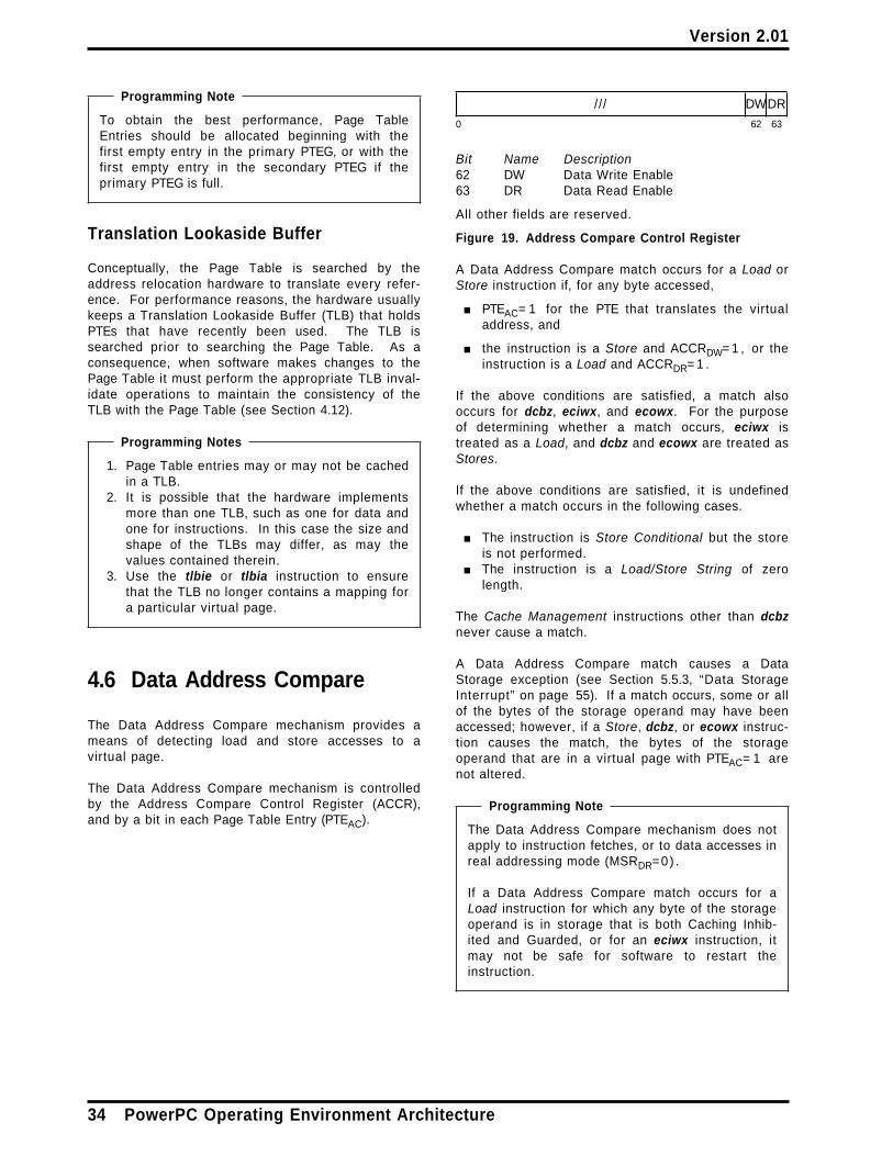
Version 2.01
Programming Note
To obtain the best performance, Page TableEntries should be allocated beginning with thefirst empty entry in the primary PTEG, or with thefirst empty entry in the secondary PTEG if theprimary PTEG is full.
Translation Lookaside Buffer
Conceptually, the Page Table is searched by theaddress relocation hardware to translate every refer-ence. For performance reasons, the hardware usuallykeeps a Translation Lookaside Buffer (TLB) that holdsPTEs that have recently been used. The TLB issearched prior to searching the Page Table. As aconsequence, when software makes changes to thePage Table it must perform the appropriate TLB inval-idate operations to maintain the consistency of theTLB with the Page Table (see Section 4.12).
Programming Notes
1. Page Table entries may or may not be cachedin a TLB.
2. It is possible that the hardware implementsmore than one TLB, such as one for data andone for instructions. In this case the size andshape of the TLBs may differ, as may thevalues contained therein.
3. Use the tlbie or tlbia instruction to ensurethat the TLB no longer contains a mapping fora particular virtual page.
4.6 Data Address Compare
The Data Address Compare mechanism provides ameans of detecting load and store accesses to avirtual page.
The Data Address Compare mechanism is controlledby the Address Compare Control Register (ACCR),and by a bit in each Page Table Entry (PTEAC).
/// DWDR
0 62 63
Bit Name Description62 DW Data Write Enable63 DR Data Read Enable
All other fields are reserved.
Figure 19. Address Compare Control Register
A Data Address Compare match occurs for a Load orStore instruction if, for any byte accessed,
■ PTEAC= 1 for the PTE that translates the virtualaddress, and
■ the instruction is a Store and ACCRDW= 1 , or theinstruction is a Load and ACCRDR= 1 .
If the above conditions are satisfied, a match alsooccurs for dcbz, eciwx, and ecowx. For the purposeof determining whether a match occurs, eciwx istreated as a Load, and dcbz and ecowx are treated asStores.
If the above conditions are satisfied, it is undefinedwhether a match occurs in the following cases.
■ The instruction is Store Conditional but the storeis not performed.
■ The instruction is a Load/Store String of zerolength.
The Cache Management instructions other than dcbznever cause a match.
A Data Address Compare match causes a DataStorage exception (see Section 5.5.3, “Data StorageInterrupt” on page 55). If a match occurs, some or allof the bytes of the storage operand may have beenaccessed; however, if a Store, dcbz, or ecowx instruc-tion causes the match, the bytes of the storageoperand that are in a virtual page with PTEAC= 1 arenot altered.
Programming Note
The Data Address Compare mechanism does notapply to instruction fetches, or to data accesses inreal addressing mode (MSRDR=0) .
If a Data Address Compare match occurs for aLoad instruction for which any byte of the storageoperand is in storage that is both Caching Inhib-ited and Guarded, or for an eciwx instruction, itmay not be safe for software to restart theinstruction.
34 PowerPC Operating Environment Architecture

Version 2.01
4.7 Data Address Breakpoint
The Data Address Breakpoint mechanism provides ameans of detecting load and store accesses to a des-ignated doubleword. The address comparison is doneon an effective address, and is done independent ofwhether address translation is enabled or disabled.
The Data Address Breakpoint mechanism is controlledby the Data Address Breakpoint Register (DABR).
DAB BT DWDR
0 61 63
Bit(s) Name Description0:60 DAB Data Address Breakpoint61 BT Breakpoint Translation Enable62 DW Data Write Enable63 DR Data Read Enable
Figure 20. Data Address Breakpoint Register
The DABR is a hypervisor resource; see Section 1.7,“Logical Partitioning (LPAR)” on page 4.
A Data Address Breakpoint match occurs for a Loador Store instruction if, for any byte accessed,
■ EA0:60=DABR DAB, and■ MSRDR=DABR BT, and■ the instruction is a Store and DABRDW= 1 , or the
instruction is a Load and DABRDR= 1 .
In 32-bit mode the high-order 32 bits of the EA aretreated as zeros for the purpose of detecting a match.
If the above conditions are satisfied, a match alsooccurs for eciwx and ecowx. For the purpose ofdetermining whether a match occurs, eciwx is treatedas a Load, and ecowx is treated as a Store.
If the above conditions are satisfied, it is undefinedwhether a match occurs in the following cases.
■ The instruction is Store Conditional but the storeis not performed.
■ The instruction is a Load/Store String of zerolength.
■ The instruction is dcbz. (For the purpose ofdetermining whether a match occurs, dcbz istreated as a Store.)
The Cache Management instructions other than dcbznever cause a match.
A Data Address Breakpoint match causes a DataStorage exception (see Section 5.5.3, “Data StorageInterrupt” on page 55). If a match occurs, some or allof the bytes of the storage operand may have beenaccessed; however, if a Store or ecowx instructioncauses the match, the storage operand is not alteredif the instruction is one of the following:
■ any Store instruction that causes an atomicaccess
■ ecowx
Programming Note
The Data Address Breakpoint mechanism doesnot apply to instruction fetches.
If a Data Address Breakpoint match occurs for aLoad instruction for which any byte of the storageoperand is in storage that is both Caching Inhib-ited and Guarded, or for an eciwx instruction, itmay not be safe for software to restart theinstruction.
4.8 Storage Control Bits
When address translation is enabled, each storageaccess is performed under the control of the PageTable Entry used to translate the effective address.Each Page Table Entry contains storage control bitsthat specify the presence or absence of the corre-sponding storage control attribute (see the sectionentitled “Storage Control Attributes” in Book II,PowerPC Virtual Environment Architecture) for allaccesses translated by the entry, as shown inFigure 21. The bits are called W, I, M, and G.
Chapter 4. Storage Control 35

Version 2.01
Figure 21. Storage control bits
Instructions are not fetched from storage for whichthe G bit in the Page Table Entry is set to 1 (seeSection 4.10, “Storage Protection” on page 39).
Programming Note
In a uniprocessor system in which only theprocessor has caches, correct coherent executiondoes not require the processor to access storageas Memory Coherence Required, and accessingstorage as not Memory Coherence Required maygive better performance.
4.8.1 Storage Control Bit Restrictions
All combinations of W, I, M, and G values are sup-ported except those for which both W and I are 1.
Programming Note
If an application program requests both the WriteThrough Required and the Caching Inhibited attri-butes for a given storage location, the operatingsystem should set the I bit to 1 and the W bit to 0.
The value of the I bit must be the same for allaccesses to a given real page.
The value of the W bit must be the same for allaccesses to a given real page.
4.8.2 Altering the Storage Control Bits
When changing the value of the I bit for a given realpage from 0 to 1, software must set the I bit to 1 andthen flush all copies of locations in the page from thecaches using dcbf and icbi before permitting anyother accesses to the page.
When changing the value of the W bit for a given realpage from 0 to 1, software must ensure that noprocessor modifies any location in the page until afterall copies of locations in the page that are consideredto be modified in the data caches have been copied tomain storage using dcbst or dcbf.
When changing the value of the M bit for a given realpage, software must ensure that all data caches areconsistent with main storage. The actions required todo this to are system-dependent.
Programming Note
For example, when changing the M bit in somedirectory-based systems, software may berequired to execute dcbf instructions on eachprocessor to flush all storage locations accessedwith the old M value before permitting thelocations to be accessed with the new M value.
Additional requirements for changing the storagecontrol bits are given in Section 4.12, “Page TableUpdate Synchronization Requirements” on page 48.
Bit Storage Control Attribute
W1 0 − not Write Through Required1 − Write Through Required
I 0 − not Caching Inhibited1 − Caching Inhibited
M2 0 − not Memory Coherence Required1 − Memory Coherence Required
G 0 − not Guarded1 − Guarded
1. Support for the 1 value of the W bit is optional.Implementations that do not support the 1 valuetreat the bit as reserved and assume its valueto be 0.
2. Support for the 0 value of the M bit is optional.Implementations that do not support the 0 valueassume the value of the bit to be 1, and mayeither preserve the value of the bit or write it as 1.
36 PowerPC Operating Environment Architecture

Version 2.01
4.9 Reference and ChangeRecording
If address translation is enabled (MSRIR= 1 orMSRDR=1) , Reference (R) and Change (C) bits aremaintained in the Page Table Entry that is used totranslate the virtual address. If the storage operandof a Load or Store instruction crosses a virtual pageboundary, the accesses to the components of theoperand in each page are treated as separate andindependent accesses to each of the pages for thepurpose of setting the Reference and Change bits.
Reference and Change bits are set by the processoras described below. Setting the bits need not beatomic with respect to performing the access thatcaused the bits to be updated. An attempt to accessstorage may cause one or more of the bits to be set(as described below) even if the access is not per-formed. The bits are updated in the Page Table Entryif the new value would otherwise be different from theold, as determined by examining either the PageTable Entry or any corresponding lookaside informa-tion maintained by the processor (e.g., in a TLB).
Reference Bit
The Reference bit is set to 1 if the correspondingaccess (load, store, or instruction fetch) is requiredby the sequential execution model and is per-formed. Otherwise the Reference bit may be set to1 if the corresponding access is attempted, eitherin-order or out-of-order, even if the attempt causesan exception.
Change Bit
The Change bit is set to 1 if a Store instruction isexecuted and the store is performed. Otherwisethe Change bit may be set to 1 if a Store instructionis executed and the store is permitted by thestorage protection mechanism and, if the Storeinstruction is executed out-of-order, the instructionwould be required by the sequential executionmodel in the absence of the following kinds of inter-rupts:
■ system-caused interrupts (i.e., System Reset,Machine Check, External, and Decrementerinterrupts)
■ Floating-Point Enabled Exception type Programinterrupts when the processor is in an Impre-cise mode
Programming Note
Even though the execution of a Store instruc-tion causes the Change bit to be set to 1, thestore might not be performed or might be onlypartially performed in cases such as the fol-lowing.
■ A Store Conditional instruction (stwcx. orstdcx.) is executed, but no store is per-formed.
■ A Store String Word Indexed instruction(stswx) is executed, but the length is zero.
■ The Store instruction causes a DataStorage exception (for which setting theChange bit is not prohibited).
■ The Store instruction causes an Alignmentexception.
■ The Page Table Entry that translates thevirtual address of the storage operand isaltered such that the new contents of thePage Table Entry preclude performing thestore (e.g., the PTE is made invalid, or thePP bits are changed).
For example, when executing a Storeinstruction, the processor may search thePage Table for the purpose of setting theChange bit and then reexecute the instruc-tion. When reexecuting the instruction, theprocessor may search the Page Table asecond time. If the Page Table Entry hasmeanwhile been altered, by a program exe-cuting on another processor, the secondsearch may obtain the new contents, whichmay preclude the store.
■ A system-caused interrupt occurs beforethe store has been performed.
Figure 22 on page 38 summarizes the rules forsetting the Reference and Change bits. The tableapplies to each atomic storage reference. It shouldbe read from the top down; the first line matching agiven situation applies. For example, if stwcx. failsdue to both a storage protection violation and the lackof a reservation, the Change bit is not altered.
In the figure, the “ Load-type” instructions are theLoad instructions described in Books I and II, eciwx,and the Cache Management instructions that aretreated as Loads. The “ Store-type” instructions arethe Store instructions described in Books I and II,ecowx, and the Cache Management instructions thatare treated as Stores. The “ordinary” Load and Storeinstructions are those described in Books I and II.“set ” means “set to 1”. When the processorupdates the Reference and Change bits in the PageTable Entry, the accesses are performed as describedin Section 4.2.6.2, “Storage Control Attributes for RealAddressing Mode and for Implicit Storage Accesses”
Chapter 4. Storage Control 37
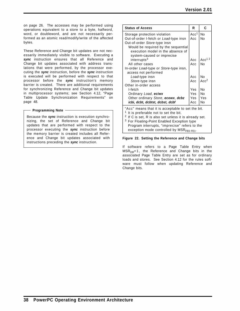
Version 2.01
on page 26. The accesses may be performed usingoperations equivalent to a store to a byte, halfword,word, or doubleword, and are not necessarily per-formed as an atomic read/modify/write of the affectedbytes.
These Reference and Change bit updates are not nec-essarily immediately visible to software. Executing async instruction ensures that all Reference andChange bit updates associated with address trans-lations that were performed, by the processor exe-cuting the sync instruction, before the sync instructionis executed will be performed with respect to thatprocessor before the sync instruction's memorybarrier is created. There are additional requirementsfor synchronizing Reference and Change bit updatesin multiprocessor systems; see Section 4.12, “PageTable Update Synchronization Requirements” onpage 48.
Programming Note
Because the sync instruction is execution synchro-nizing, the set of Reference and Change bitupdates that are performed with respect to theprocessor executing the sync instruction beforethe memory barrier is created includes all Refer-ence and Change bit updates associated withinstructions preceding the sync instruction.
Status of Access R C
Storage protection violation Acc1 NoOut-of-order I-fetch or Load-type insn Acc NoOut-of-order Store-type insn
Would be required by the sequentialexecution model in the absence ofsystem-caused or impreciseinterrupts3 Acc Acc1 2
All other cases Acc NoIn-order Load-type or Store-type insn,
access not performedLoad-type insn Acc NoStore-type insn Acc Acc2
Other in-order accessI-fetch Yes NoOrdinary Load, eciwx Yes NoOther ordinary Store, ecowx, dcbz Yes Yesicbi, dcbt, dcbtst, dcbst, dcbf Acc No
“Acc ” means that it is acceptable to set the bit.1 It is preferable not to set the bit.2 If C is set, R is also set unless it is already set.3 For Floating-Point Enabled Exception type
Program interrupts, “ imprecise” refers to theexception mode controlled by MSRFE0 FE1.
Figure 22. Setting the Reference and Change bits
If software refers to a Page Table Entry whenMSRDR= 1 , the Reference and Change bits in theassociated Page Table Entry are set as for ordinaryloads and stores. See Section 4.12 for the rules soft-ware must follow when updating Reference andChange bits.
38 PowerPC Operating Environment Architecture

Version 2.01
4.10 Storage Protection
The storage protection mechanism provides a meansfor selectively granting instruction fetch access,granting read access, granting read/write access, andprohibiting access to areas of storage based on anumber of control criteria.
The operation of the protection mechanism dependson whether address translation is enabled (MSRIR= 1or MSRDR= 1 , as appropriate for the access) or disa-bled (MSRIR= 0 or MSRDR= 0 , as appropriate for theaccess).
If an instruction fetch is not permitted by the pro-tection mechanism, an Instruction Storage exceptionis generated. If a data access is not permitted by theprotection mechanism, a Data Storage exception isgenerated. (See Section 4.2.1, “Storage Exceptions”on page 22.)
When address translation is enabled, a protectiondomain is a range of unmapped effective addresses, avirtual page, or a segment. When address translationis disabled and LPES/LPES1= 1 there are two pro-tection domains: the set of effective addresses thatare less than the value specified by the RMLR, and allother effective addresses. When address translationis disabled and LPES/LPES1= 0 the entire effectiveaddress space comprises a single protection domain.A protection boundary is a boundary between pro-tection domains.
4.10.1 Storage Protection, AddressTranslation Enabled
When address translation is enabled, the protectionmechanism is controlled by the following.
■ MSRPR, which distinguishes between supervisor(privileged) state and problem state
■ Ks and Kp, the supervisor (privileged) state andproblem state storage key bits in the SLB entryused to translate the effective address
■ PP, page protection bits in the Page Table Entryused to translate the effective address
■ For instruction fetches only:— the N (No-execute) value used for the access
(see Section 4.5.3)— PTEG, the G (Guarded) bit in the Page Table
Entry used to translate the effective address
Using the above values, the following rules areapplied.
1. For an instruction fetch, the access is not per-mitted if the N value is 1 or if PTEG= 1 .
2. For any access except an instruction fetch that isnot permitted by rule 1, a “Key ” value is com-puted using the following formula:
Key ← (Kp & MSRPR) | (Ks & ¬MSRPR)
Using the computed Key, Figure 23 is applied.An instruction fetch is permitted for any entry inthe figure except “no access”. A load is per-mitted for any entry except “no access”. A storeis permitted only for entries with “read/write”.
Key PP Access Authority
0 00 read/write0 01 read/write0 10 read/write0 11 read only
1 00 no access1 01 read only1 10 read/write1 11 read only
Figure 23. PP bit protection states, address trans-lation enabled
4.10.2 Storage Protection, AddressTranslation Disabled
When address translation is disabled, the protectionmechanism is controlled by the following (see Section1.7, “Logical Partitioning (LPAR)” on page 4 andSection 4.2.6, “Real Addressing Mode” on page 25).
■ LPES/LPES1, which distinguishes between the twomodes of using the LPAR facility
■ MSRHV, which distinguishes between hypervisorstate and other privilege states
■ RMLR, which specifies the real mode limit value
Using the above values, Figure 24 is applied. Theaccess is permitted for any entry in the figure except“no access”.
Figure 24. Protection states, address translation disa-bled
Programming Note
The comparison described in note 1 in Figure 24ignores bits 0:1 of the effective address and mayignore bits 2:63− m; see Section 4.2.6.
LPES/LPES1 HV Access Authority
0 0 no access0 1 read/write1 0 read/write or no access1
1 1 read/write
1. If the effective address for the access is lessthan the value specified by the RMLR theaccess authority is read/write; otherwise theaccess is not permitted.
Chapter 4. Storage Control 39

Version 2.01
4.11 Storage Control Instructions
4.11.1 Cache ManagementInstructions
This section describes aspects of cache managementthat are relevant only to operating system program-mers.
For a dcbz instruction that causes the target block tobe newly established in the data cache without beingfetched from main storage, the processor need notverify that the associated real address is valid. Theexistence of a data cache block that is associated withan invalid real address (see Section 4.2.8) can causea delayed Machine Check interrupt or a delayedCheckstop.
Each implementation provides an efficient means bywhich software can ensure that all blocks that areconsidered to be modified in the data cache havebeen copied to main storage before the processorenters any power conserving mode in which datacache contents are not maintained. The means aredescribed in the Book IV, PowerPC ImplementationFeatures document for the implementation.
4.11.2 Synchronize Instruction
The Synchronize instruction is described in Book II,PowerPC Virtual Environment Architecture, but only atthe level required by an application programmer(sync with L = 0 or L=1) . This section describes prop-erties of the instruction that are relevant only to oper-ating system and hypervisor software programmers.This variant of the Synchronize instruction is desig-nated the page table entry sync and is specified bythe extended mnemonic ptesync (equivalent to syncwith L=2) .
The ptesync instruction has all of the properties ofsync with L = 0 and also the following additional prop-erties.
■ The memory barrier created by the ptesyncinstruction provides an ordering function for thestorage accesses associated with all instructionsthat are executed by the processor executing theptesync instruction and, as elements of set A, forall Reference and Change bit updates associatedwith additional address translations that wereperformed, by the processor executing theptesync instruction, before the ptesync instructionis executed. The applicable pairs are all pairsai,bj in which bj is a data access and ai is not aninstruction fetch.
■ The ptesync instruction causes all Reference andChange bit updates associated with addresstranslations that were performed, by the
processor executing the ptesync instruction,before the ptesync instruction is executed, to beperformed with respect to that processor beforethe ptesync instruction's memory barrier iscreated.
■ The ptesync instruction provides an orderingfunction for all stores to the Page Table causedby Store instructions preceding the ptesyncinstruction with respect to searches of the PageTable that are performed, by the processor exe-cuting the ptesync instruction, after the ptesyncinstruction completes. Executing a ptesyncinstruction ensures that all such stores will beperformed, with respect to the processor exe-cuting the ptesync instruction, before any implicitaccesses to the affected Page Table Entries, bysuch Page Table searches, are performed withrespect to that processor.
■ In conjunction with the tlbie and tlbsyncinstructions, the ptesync instruction provides anordering function for TLB invalidations andrelated storage accesses on other processors asdescribed in the tlbsync instruction description onpage 47.
Programming Note
For instructions following a ptesync instruc-tion, the memory barrier need not orderimplicit storage accesses for purposes ofaddress translation and reference and changerecording.
The functions performed by the ptesyncinstruction may take a significant amount oftime to complete, so this form of the instruc-tion should be used only if the functions listedabove are needed. Otherwise sync with L = 0should be used (or sync with L = 1 or eieio, ifappropriate).
Section 4.12, “Page Table Update Synchroni-zation Requirements” on page 48 givesexamples of uses of ptesync.
4.11.3 Lookaside Buffer Management
All implementations have a Segment Lookaside Buffer(SLB), and provide the SLB Management instructionsdescribed in Section 4.11.3.1.
For performance reasons, most implementations havea Translation Lookaside Buffer (TLB), which is a cacheof recently used Page Table Entries (PTEs). The TLBis not necessarily kept consistent with the Page Tablein main storage. When software alters the contents ofa PTE, it must also invalidate all corresponding TLBentries.
Each implementation that has a TLB provides ameans by which software can do the following.
40 PowerPC Operating Environment Architecture

Version 2.01
■ Invalidate the TLB entry that translates a giveneffective address
■ Invalidate all TLB entries
An implementation may provide one or more of theTLB Management instructions described in Section4.11.3.2 in order to satisfy requirements in the pre-ceding list. Alternatively, an algorithm may be giventhat performs one of the functions listed above (aloop invalidating individual TLB entries may be usedto invalidate the entire TLB, for example), or differentinstructions may be provided. Such algorithms orinstructions are described in Book IV, PowerPC Imple-mentation Features. Because most implementationshave a TLB and also provide instructions similar oridentical to the TLB Management instructionsdescribed in Section 4.11.3.2, other sections of theBooks assume that the TLB exists and that theinstructions described in Section 4.11.3.2 are pro-vided.
An implementation that does not have a TLB treatsthe corresponding instructions (tlbie, tlbia, andtlbsync) either as no-ops or as illegal instructions.
Programming Note
Because the presence, absence, and exactsemantics of the TLB Management instructionsare implementation-dependent, it is recommendedthat system software “encapsulate” uses of theseinstructions into subroutines to minimize theimpact of moving from one implementation toanother.
Programming Note
The function of all the instructions described inSections 4.11.3.1 and 4.11.3.2 is independent ofwhether address translation is enabled or disa-bled.
For a discussion of software synchronizationrequirements when invalidating SLB and TLBentries, see Chapter 7, “Synchronization Require-ments for Context Alterations” on page 71.
4.11.3.1 SLB Management Instructions
Programming Note
Accesses to a given SLB entry caused by theinstructions described in this section obey thesequential execution model with respect to thecontents of the entry and with respect to datadependencies on those contents. That is, if aninstruction sequence contains two or more ofthese instructions, when the sequence has com-pleted, the final state of the SLB entry and ofGeneral Purpose Registers is as if the instructionshad been executed in program order.
However, software synchronization is required inorder to ensure that any alterations of the entrytake effect correctly with respect to address trans-lation; see Chapter 7.
SLB Invalidate Entry X-form
slbie RB
31 /// /// RB 434 /
0 6 11 16 21 31
esid ← (RB)0:35class ← (RB)36if class = SLBEC for SLB entry that translates
or most recently translated esidthen for SLB entry (if any) that translates esid
SLBEV ← 0all other fields of SLBE ← undefined
else translation of esid ← undefined
Let the Effective Segment ID (ESID) be (RB)0:35. Letthe class be (RB)36. The class value must be thesame as the Class value in the SLB entry that trans-lates the ESID, or the Class value that was in the SLBentry that most recently translated the ESID if thetranslation is no longer in the SLB; if the class valueis not the same, the results of translating effectiveaddresses for which EA0:35=ESID are undefined, andthe next paragraph need not apply.
If the SLB contains an entry that translates the speci-fied ESID, the V bit in that entry is set to 0, makingthe entry invalid, and the remaining fields of the entryare set to undefined values.
(RB)37:63 must be zeroes.
If this instruction is executed in 32-bit mode, (RB)0:31must be zeros (i.e., the ESID must be in the range0-15).
This instruction is privileged.
Chapter 4. Storage Control 41

Version 2.01
Special Registers Altered:None
Programming Note
The only SLB entry that is invalidated is the entry(if any) that translates the specified ESID.
slbie does not affect SLBs on other processors.
Programming Note
The reason the class value specified by slbie mustbe the same as the Class value that is or was inthe relevant SLB entry is that the processor mayuse these values to optimize invalidation of imple-mentation-specific lookaside information used inaddress translation. If the value specified by slbiediffers from the value that is or was in the rele-vant SLB entry, these optimizations may produceincorrect results. (An example of implementa-tion-specific address translation lookaside infor-mation is the set of recently used translations ofeffective addresses to real addresses that someprocessors maintain in an Effective to RealAddress Translation (ERAT) lookaside buffer.)
The recommended use of the Class field is toclassify SLB entries according to the expectedlongevity of the translations they contain, or asimilar property such as whether the translationsare used by all programs or only by a singleprogram. If this is done and the processor invali-dates certain implementation-specific lookasideinformation based only on the specified classvalue, an slbie instruction that invalidates a short-lived translation will preserve such lookasideinformation for long-lived translations.
If the optional “Bridge” facility is implemented(see Section 9.1), the Move To Segment Registerinstructions create SLB entries in which the Classvalue is 0.
SLB Invalidate All X-form
slbia
31 /// /// /// 498 /
0 6 11 16 21 31
for each SLB entry except SLB entry 0SLBEV ← 0all other fields of SLBE ← undefined
For all SLB entries except SLB entry 0, the V bit inthe entry is set to 0, making the entry invalid, and theremaining fields of the entry are set to undefinedvalues. SLB entry 0 is not altered.
This instruction is privileged.
Special Registers Altered:None
Programming Note
slbia does not affect SLBs on other processors.
Programming Note
If slbia is executed when instruction addresstranslation is enabled (MSRIR=1) , software canensure that attempting to fetch the instruction fol-lowing the slbia does not cause an InstructionSegment interrupt by placing the slbia and thesubsequent instruction in the effective segmentmapped by SLB entry 0. (The preceding assumesthat no other interrupts occur between executingthe slbia and executing the subsequent instruc-tion.)
42 PowerPC Operating Environment Architecture

Version 2.01
SLB Move To Entry X-form
slbmte RS,RB
31 RS /// RB 402 /
0 6 11 16 21 31
The SLB entry specified by bits 52:63 of register RB isloaded from register RS and from the remainder ofregister RB. The contents of these registers areinterpreted as shown in Figure 25.
RS
VSID KsKpNLC 0s
0 52 56 63
RB
ESID V 0s index
0 35 37 52 63
RS0:51 VSIDRS52 KsRS53 KpRS54 NRS55 LRS56 CRS57:63 must be 0b000_0000
RB0:35 ESIDRB36 VRB37:51 must be 0b000 | | 0x000RB52:63 index, which selects the SLB entry
Figure 25. GPR contents for slbmte
On implementations that support a virtual addresssize of only n bits, n< 80, (RS)0:79− n must be zeros.
High-order bits of (RB)52:63 that correspond to SLBentries beyond the size of the SLB provided by theimplementation must be zeros.
If this instruction is executed in 32-bit mode, (RB)0:31must be zeros (i.e., the ESID must be in the range0-15).
This instruction cannot be used to invalidate an SLBentry.
This instruction is privileged.
Special Registers Altered:None
Programming Note
The reason slbmte cannot be used to invalidatean SLB entry is that it does not necessarily affectimplementation-specific address translation look-aside information. slbie (or slbia) must be usedfor this purpose.
Chapter 4. Storage Control 43
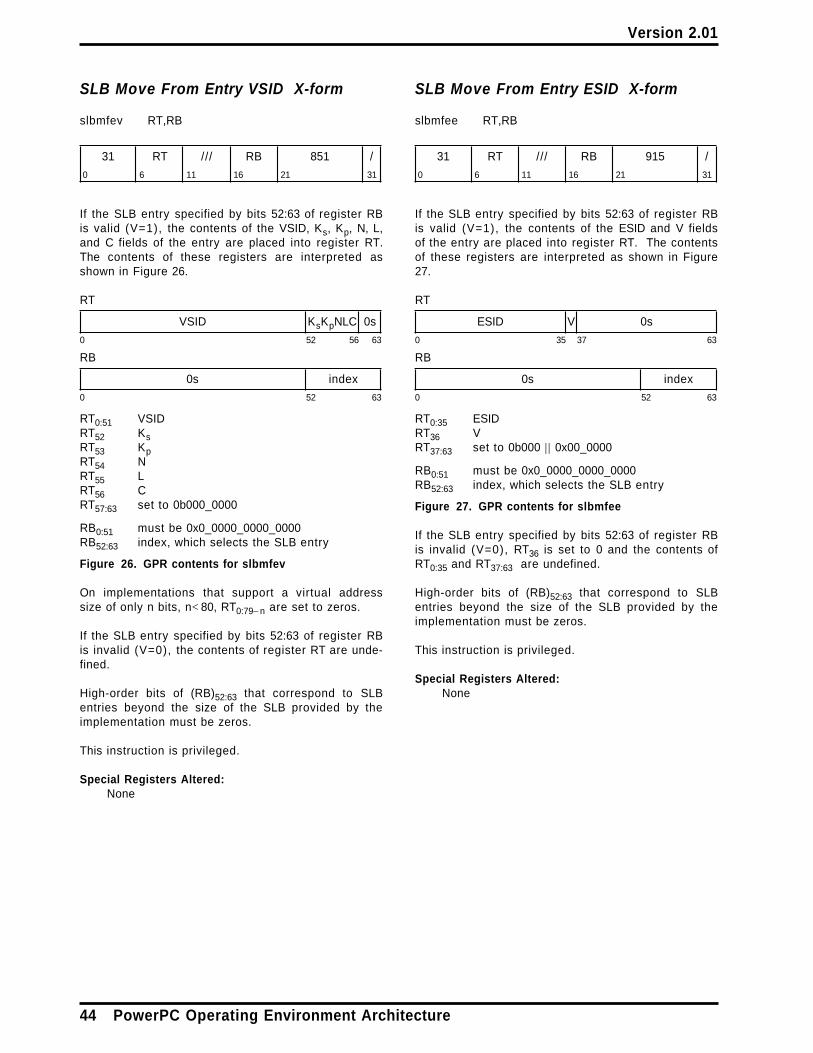
Version 2.01
SLB Move From Entry VSID X-form
slbmfev RT,RB
31 RT /// RB 851 /
0 6 11 16 21 31
If the SLB entry specified by bits 52:63 of register RBis valid (V=1), the contents of the VSID, Ks, Kp, N, L,and C fields of the entry are placed into register RT.The contents of these registers are interpreted asshown in Figure 26.
RT
VSID KsKpNLC 0s
0 52 56 63
RB
0s index
0 52 63
RT0:51 VSIDRT52 KsRT53 KpRT54 NRT55 LRT56 CRT57:63 set to 0b000_0000
RB0:51 must be 0x0_0000_0000_0000RB52:63 index, which selects the SLB entry
Figure 26. GPR contents for slbmfev
On implementations that support a virtual addresssize of only n bits, n< 80, RT0:79− n are set to zeros.
If the SLB entry specified by bits 52:63 of register RBis invalid (V=0), the contents of register RT are unde-fined.
High-order bits of (RB)52:63 that correspond to SLBentries beyond the size of the SLB provided by theimplementation must be zeros.
This instruction is privileged.
Special Registers Altered:None
SLB Move From Entry ESID X-form
slbmfee RT,RB
31 RT /// RB 915 /
0 6 11 16 21 31
If the SLB entry specified by bits 52:63 of register RBis valid (V=1), the contents of the ESID and V fieldsof the entry are placed into register RT. The contentsof these registers are interpreted as shown in Figure27.
RT
ESID V 0s
0 35 37 63
RB
0s index
0 52 63
RT0:35 ESIDRT36 VRT37:63 set to 0b000 | | 0x00_0000
RB0:51 must be 0x0_0000_0000_0000RB52:63 index, which selects the SLB entry
Figure 27. GPR contents for slbmfee
If the SLB entry specified by bits 52:63 of register RBis invalid (V=0), RT36 is set to 0 and the contents ofRT0:35 and RT37:63 are undefined.
High-order bits of (RB)52:63 that correspond to SLBentries beyond the size of the SLB provided by theimplementation must be zeros.
This instruction is privileged.
Special Registers Altered:None
44 PowerPC Operating Environment Architecture

Version 2.01
4.11.3.2 TLB Management Instructions (Optional)
TLB Invalidate Entry X-form
tlbie RB,L
[POWER mnemonic: tlbi]
31 /// L /// RB 306 /
0 6 10 11 16 21 31
if L = 0then pg_size ← 4 KBelse pg_size ← large page size
p ← log_base_2(pg_size)for each processor in the partition
for each TLB entryif (entry_VPN32:79−p = (RB)16:63−p) &
(entry_pg_size = pg_size)then TLB entry ← invalid
The contents of (RB)0:15 must be 0x0000. If the L fieldof the instruction is 1 let the page size be large; oth-erwise let the page size be 4 KB.
All TLB entries that have all of the following proper-ties are made invalid on all processors that are in thesame partition as the processor executing the tlbieinstruction.
■ The entry translates a virtual address for whichVPN32:79− p is equal to (RB)16:63− p.
■ The page size of the entry matches the page sizespecified by the L field of the instruction.
Additional TLB entries may also be made invalid onany processor that is in the same partition as theprocessor executing the tlbie instruction.
MSRSF must be 1 when this instruction is executed;otherwise the results are undefined.
The operation performed by this instruction is orderedby the eieio (or sync or ptesync) instruction withrespect to a subsequent tlbsync instruction executedby the processor executing the tlbie instruction. Theoperations caused by tlbie and tlbsync are ordered byeieio as a third set of operations, which is inde-pendent of the other two sets that eieio orders.
This instruction is privileged, and can be executedonly in hypervisor state. If it is executed in privilegedbut non-hypervisor state either a Privileged Instruc-tion type Program interrupt occurs or the results areboundedly undefined.
This instruction is optional.
See Section 4.12, “Page Table Update Synchroniza-tion Requirements” on page 48 for a description ofother requirements associated with the use of thisinstruction.
Special Registers Altered:None
Chapter 4. Storage Control 45

Version 2.01
TLB Invalidate Entry Local X-form
tlbiel RB,L
31 /// L /// RB 274 /
0 6 10 11 16 21 31
if L = 0then pg_size ← 4 KBelse pg_size ← large page size
p ← log_base_2(pg_size)for each TLB entry
if (entry_VPN32:79−p = (RB)16:63−p) &(entry_pg_size = pg_size)
then TLB entry ← invalid
The contents of (RB)0:15 must be 0x0000. If the L fieldof the instruction is 1 let the page size be large; oth-erwise let the page size be 4 KB.
All TLB entries that have all of the following proper-ties are made invalid on the processor which exe-cutes this instruction.
■ The entry translates a virtual address for whichVPN32:79− p is equal to (RB)16:63− p.
■ The page size of the entry matches the page sizespecified by the L field of the instruction.
Only TLB entries on the processor executing thisinstruction are affected.
(RB)52:63 must be zero.
MSRSF must be 1 when this instruction is executed;otherwise the results are undefined.
The operation performed by this instruction is orderedby the eieio (or sync or ptesync) instruction withrespect to a subsequent tlbsync instruction executedby the processor executing the tlbiel instruction. Theoperations caused by tlbiel and tlbsync are orderedby eieio as a third set of operations, which is inde-pendent of the other two sets that eieio orders.
This instruction is privileged, and can be executedonly in hypervisor state. If it is executed in privilegedbut non-hypervisor state either a Privileged Instruc-tion type Program interrupt occurs or the results areboundedly undefined.
This instruction is optional.
Support of large pages for tlbiel is optional. Onimplementations that do not support large pages fortlbiel, the following properties apply.
■ The syntax of the instruction is “tlbiel RB”.■ Bit 10 of the instruction is a reserved bit.■ In the RTL, the first three lines and the third from
last line are ignored.■ The last list item in the paragraph that begins
“All TLB entries ...”, namely “The page size of theentry matches the page size specified by the Lfield of the instruction”, is ignored.
See Section 4.12, “Page Table Update Synchroniza-tion Requirements” on page 48 for a description ofother requirements associated with the use of thisinstruction.
Special Registers Altered:None
Programming Note
The primary use of this instruction by hypervisorstate code is to invalidate TLB entries prior toreassigning a processor to a new logical partition.
tlbiel may be executed on a given processor evenif the sequence of tlbie - sync - tlbsync - ptesyncis being concurrently executed on a differentprocessor. In other words, no programmatic syn-chronization is required relative to the executionof tlbie or tlbiel.
To synchronize the completion of this processorlocal form of tlbie, only a ptesync is required(tlbsync should not be used).
46 PowerPC Operating Environment Architecture
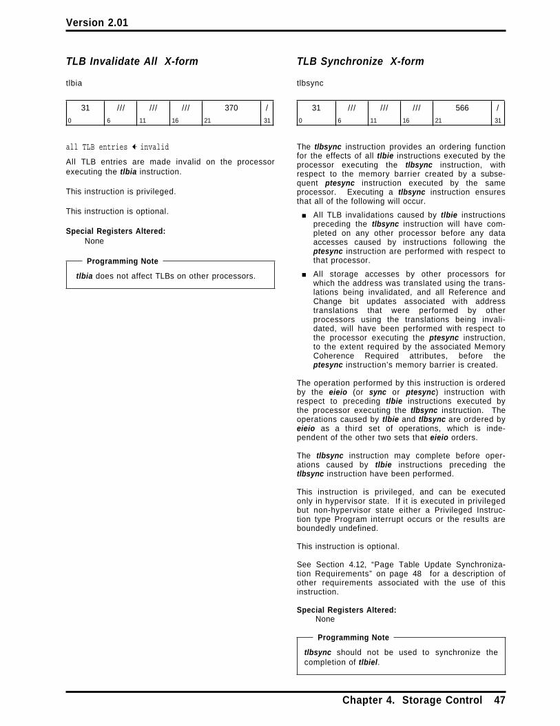
Version 2.01
TLB Invalidate All X-form
tlbia
31 /// /// /// 370 /
0 6 11 16 21 31
all TLB entries ← invalid
All TLB entries are made invalid on the processorexecuting the tlbia instruction.
This instruction is privileged.
This instruction is optional.
Special Registers Altered:None
Programming Note
tlbia does not affect TLBs on other processors.
TLB Synchronize X-form
tlbsync
31 /// /// /// 566 /
0 6 11 16 21 31
The tlbsync instruction provides an ordering functionfor the effects of all tlbie instructions executed by theprocessor executing the tlbsync instruction, withrespect to the memory barrier created by a subse-quent ptesync instruction executed by the sameprocessor. Executing a tlbsync instruction ensuresthat all of the following will occur.
■ All TLB invalidations caused by tlbie instructionspreceding the tlbsync instruction will have com-pleted on any other processor before any dataaccesses caused by instructions following theptesync instruction are performed with respect tothat processor.
■ All storage accesses by other processors forwhich the address was translated using the trans-lations being invalidated, and all Reference andChange bit updates associated with addresstranslations that were performed by otherprocessors using the translations being invali-dated, will have been performed with respect tothe processor executing the ptesync instruction,to the extent required by the associated MemoryCoherence Required attributes, before theptesync instruction's memory barrier is created.
The operation performed by this instruction is orderedby the eieio (or sync or ptesync) instruction withrespect to preceding tlbie instructions executed bythe processor executing the tlbsync instruction. Theoperations caused by tlbie and tlbsync are ordered byeieio as a third set of operations, which is inde-pendent of the other two sets that eieio orders.
The tlbsync instruction may complete before oper-ations caused by tlbie instructions preceding thetlbsync instruction have been performed.
This instruction is privileged, and can be executedonly in hypervisor state. If it is executed in privilegedbut non-hypervisor state either a Privileged Instruc-tion type Program interrupt occurs or the results areboundedly undefined.
This instruction is optional.
See Section 4.12, “Page Table Update Synchroniza-tion Requirements” on page 48 for a description ofother requirements associated with the use of thisinstruction.
Special Registers Altered:None
Programming Note
tlbsync should not be used to synchronize thecompletion of tlbiel.
Chapter 4. Storage Control 47

Version 2.01
4.12 Page Table UpdateSynchronization Requirements
This section describes rules that software shouldfollow when updating the Page Table, and includessuggested sequences of operations for some repre-sentative cases.
In the sequences of operations shown in the followingsubsections, any alteration of a Page Table Entry(PTE) that corresponds to a single line in thesequence is assumed to be done using a Storeinstruction for which the access is atomic. Appro-priate modifications must be made to thesesequences if this assumption is not satisfied (e.g., if astore doubleword operation is done using two StoreWord instructions).
All of the sequences require a context synchronizingoperation after the sequence if the new contents ofthe PTE are to be used for address translations asso-ciated with subsequent instructions.
As noted in the description of the Synchronizeinstruction in Book II, address translation associatedwith instructions which occur in program order subse-quent to the Synchronize (and this includes theptesync variant) may actually be performed prior tothe completion of the Synchronize. To ensure thatthese instructions and data which may have beenspeculatively fetched are discarded, a context syn-chronizing operation is required.
Programming Note
The context synchronizing operation after thesequence ensures that any address translationsassociated with instructions following the contextsynchronizing operation that were performedusing the old contents of the PTE will be dis-carded, with the result that these address trans-lations will be performed again using the valuesstored by the sequence (or values stored subse-quently). In many cases this context synchroniza-tion will occur naturally; for example, if thesequence is executed within an interrupt handlerthe rfid instruction that returns from the interrupthandler may provide the required context syn-chronization.
No context synchronizing operation is neededbefore any of the sequences, because (a) eachsequence begins with a store to the PTE, (b) nocontext synchronizing operation is needed beforethe corresponding Store instruction (see Note 8 ofChapter 7 on page 71), and (c) each sequence(except the sequence for resetting the Referencebit) explicitly orders subsequent operations withrespect to the store. These properties ensurethat all address translations associated withinstructions preceding the sequence will be per-formed using the old contents of the PTE.
Page Table Entries must not be changed in a mannerthat causes an implicit branch.
4.12.1 Page Table Updates
TLBs are non-coherent caches of the HTAB. TLBentries must be invalidated explicitly with one of theTLB Invalidate instructions.
Unsynchronized lookups in the HTAB continue evenwhile it is being modified. Any processor, including aprocessor on which software is modifying the HTAB,may look in the HTAB at any time in an attempt totranslate a virtual address. When modifying a PTE,software must ensure that the PTE's Valid bit is 0 ifthe PTE is inconsistent (e.g., if the RPN field is notcorrect for the current AVPN field).
Updates of Reference and Change bits by theprocessor are not synchronized with the accesses thatcause the updates. When modifying the low-orderhalf of a PTE, software must take care to avoid over-writing a processor update of these bits and to avoidhaving the value written by a Store instruction over-written by a processor update. The processor doesnot alter any other fields of the PTE.
Before permitting one or more tlbie instructions to beexecuted on a given processor in a given partitionsoftware must ensure that no other processor willexecute a “conflicting instruction” until after the fol-lowing sequence of instructions has been executed onthe given processor.
the tlbie instruction(s)eieiotlbsyncptesync
The “conflicting instructions” in this case are the fol-lowing.
■ a tlbie or tlbsync instruction, if executed onanother processor in the given partition
■ an mtspr instruction that modifies the LPIDR, ifthe modification has either of the following prop-erties.
— The old LPID value (i.e., the contents of theLPIDR just before the mtspr instruction isexecuted) is the value that identifies thegiven partition
— The new LPID value (i.e., the value specifiedby the mtspr instruction) is the value thatidentifies the given partition
Other instructions (excluding mtspr instructions thatmodify the LPIDR as described above, and excludingtlbie instructions except as shown) may be inter-leaved with the instruction sequence shown above,but the instructions in the sequence must appear inthe order shown. On uniprocessor systems, the eieioand tlbsync instructions can be omitted. Otherinstructions may be interleaved with this sequence of
48 PowerPC Operating Environment Architecture

Version 2.01
instructions, but these instructions must appear in theorder shown.
Programming Note
The eieio instruction prevents the reordering oftlbie instructions previously executed by theprocessor with respect to the subsequent tlbsyncinstruction. The tlbsync instruction and the subse-quent ptesync instruction together ensure that allstorage accesses for which the address wastranslated using the translations being invali-dated, and all Reference and Change bit updatesassociated with address translations that wereperformed using the translations being invali-dated, will be performed with respect to anyprocessor or mechanism, to the extent requiredby the associated Memory Coherence Requiredattributes, before any data accesses caused byinstructions following the ptesync instruction areperformed with respect to that processor or mech-anism.
The requirements specified above for tlbieinstructions apply also to tlbsync instructions, exceptthat the “sequence of instructions” consists solely ofthe tlbsync instruction(s) followed by a ptesyncinstruction.
Before permitting an mtspr instruction that modifiesthe LPIDR to be executed on a given processor, soft-ware must ensure that no other processor willexecute a “conflicting instruction” until after themtspr instruction followed by a context synchronizinginstruction have been executed on the givenprocessor (a context synchronizing event can be usedinstead of the context synchronizing instruction; seeChapter 7).
The “conflicting instructions” in this case are the fol-lowing.
■ a tlbie or tlbsync instruction, if executed on aprocessor in either of the following partitions
— the partition identified by the old LPID value
— the partition identified by the new LPID value
Programming Note
The restrictions specified above regarding modi-fying the LPIDR apply even on uniprocessorsystems, and even if the new LPID value is equalto the old LPID value.
Similarly, when a tlbsync instruction has been exe-cuted by a processor in a given partition, a ptesyncinstruction must be executed by that processor beforea tlbie or tlbsync instruction is executed by anotherprocessor in that partition.
The sequences of operations shown in the followingsubsections assume a multiprocessor environment.In a uniprocessor environment the tlbsync can beomitted, as can the eieio that separates the tlbie fromthe tlbsync. In a multiprocessor environment, whentlbiel is used instead of tlbie in a Page Table update,the synchronization requirements are the same aswhen tlbie is used in a uniprocessor environment.
Programming Note
For all of the sequences shown in the followingsubsections, if it is necessary to communicatecompletion of the sequence to software runningon another processor, the ptesync instruction atthe end of the sequence should be followed by aStore instruction that stores a chosen value tosome chosen storage location X. The memorybarrier created by the ptesync instruction ensuresthat if a Load instruction executed by anotherprocessor returns the chosen value from locationX, the sequence's stores to the Page Table havebeen performed with respect to that otherprocessor. The Load instruction that returns thechosen value should be followed by a context syn-chronizing instruction in order to ensure that allinstructions following the context synchronizinginstruction will be fetched and executed using thevalues stored by the sequence (or values storedsubsequently). (These instructions may havebeen fetched or executed out-of-order using theold contents of the PTE.)
This Note assumes that the Page Table andlocation X are in storage that is Memory Coher-ence Required.
Chapter 4. Storage Control 49

Version 2.01
4.12.1.1 Adding a Page Table Entry
This is the simplest Page Table case. The Valid bit ofthe old entry is assumed to be 0. The followingsequence can be used to create a PTE, maintain aconsistent state, and ensure that a subsequent refer-ence to the virtual address translated by the newentry will use the correct real address and associatedattributes.
PTERPN,AC,R,C,WIMG,N,PP ← new valueseieio /* order 1st update before 2nd */PTEAVPN,SW,H,V ← new values (V=1)ptesync /* order updates before next
Page Table search and beforenext data access. */
4.12.1.2 Modifying a Page Table Entry
General Case
If a valid entry is to be modified and the translationinstantiated by the entry being modified is to be inval-idated, the following sequence can be used to modifythe PTE, maintain a consistent state, ensure that thetranslation instantiated by the old entry is no longeravailable, and ensure that a subsequent reference tothe virtual address translated by the new entry willuse the correct real address and associated attri-butes. (The sequence is equivalent to deleting thePTE and then adding a new one; see Sections 4.12.1.3and 4.12.1.1.)
PTEV ← 0 /* (other fields don't matter) */ptesync /* order update before tlbie and
before next Page Table search */tlbie(old_VPN32:79−p,old_L) /* invalidate old
translation */eieio /* order tlbie before tlbsync */tlbsync /* order tlbie before ptesync */ptesync /* order tlbie, tlbsync and 1st
update before 2nd update */PTERPN,AC,R,C,WIMG,N,PP ← new valueseieio /* order 2nd update before 3rd */PTEAVPN,SW,H,V ← new values (V=1)ptesync /* order 2nd and 3rd updates before
next Page Table search andbefore next data access */
Resetting the Reference Bit
If the only change being made to a valid entry is toset the Reference bit to 0, a simpler sequence suf-fices because the Reference bit need not be main-tained exactly.
oldR ← PTER /* get old R */if oldR = 1 then
PTER ← 0 /* store byte (R=0, other bitsunchanged) */
tlbie(VPN32:79−p,L) /* invalidate entry */eieio /* order tlbie before tlbsync */tlbsync /* order tlbie before ptesync */ptesync /* order tlbie, tlbsync, and update
before next Page Table searchand before next data access */
Modifying the Virtual Address
If the virtual address translated by a valid PTE is tobe modified and the new virtual address hashes tothe same two PTEGs as does the old virtual address,the following sequence can be used to modify thePTE, maintain a consistent state, ensure that thetranslation instantiated by the old entry is no longeravailable, and ensure that a subsequent reference tothe virtual address translated by the new entry willuse the correct real address and associated attri-butes.
PTEAVPN,SW,H,V ← new values (V=1)ptesync /* order update before tlbie and
before next Page Table search */tlbie(old_VPN32:79−p,old_L) /* invalidate old
translation */eieio /* order tlbie before tlbsync */tlbsync /* order tlbie before ptesync */ptesync /* order tlbie, tlbsync, and update
before next data access */
To modify the AC, N, or PP bits without overwriting aReference or Change bit update being performed bythe processor or by some other processor, asequence similar to that shown above can be usedexcept that the first line would be replaced by aptesync instruction followed by a loop containing aldarx/stdcx. pair that emulates an atomic “Compareand Swap” of the low-order doubleword of the PTE.(See the section entitled “Atomic Update Primitives”in Book II, PowerPC Virtual Environment Architecturefor a description of “Compare and Swap”.)
4.12.1.3 Deleting a Page Table Entry
The following sequence can be used to ensure thatthe translation instantiated by an existing entry is nolonger available.
PTEV ← 0 /* (other fields don't matter) */ptesync /* order update before tlbie and
before next Page Table search */tlbie(old_VPN32:79−p,old_L) /* invalidate old
translation */eieio /* order tlbie before tlbsync */tlbsync /* order tlbie before ptesync */ptesync /* order tlbie, tlbsync, and update
before next data access */
50 PowerPC Operating Environment Architecture

Version 2.01
Chapter 5. Interrupts
5.1 Overview . . . . . . . . . . . . . . . . 515.2 Interrupt Synchronization . . . . . . 515.3 Interrupt Classes . . . . . . . . . . . 525.3.1 Precise Interrupt . . . . . . . . . . 525.3.2 Imprecise Interrupt . . . . . . . . . 525.4 Interrupt Processing . . . . . . . . . 535.5 Interrupt Definitions . . . . . . . . . 545.5.1 System Reset Interrupt . . . . . . 555.5.2 Machine Check Interrupt . . . . . 555.5.3 Data Storage Interrupt . . . . . . 555.5.4 Data Segment Interrupt . . . . . . 575.5.5 Instruction Storage Interrupt . . . 585.5.6 Instruction Segment Interrupt . . 585.5.7 External Interrupt . . . . . . . . . . 595.5.8 Alignment Interrupt . . . . . . . . 59
5.5.9 Program Interrupt . . . . . . . . . 605.5.10 Floating-Point Unavailable
Interrupt . . . . . . . . . . . . . . . . . . 615.5.11 Decrementer Interrupt . . . . . . 615.5.12 Hypervisor Decrementer
Interrupt (POWER4+ only) . . . . . . . 625.5.13 System Call Interrupt . . . . . . . 625.5.14 Trace Interrupt . . . . . . . . . . 635.5.15 Performance Monitor Interrupt
(Optional) . . . . . . . . . . . . . . . . . 635.6 Partially Executed Instructions . . . 635.7 Exception Ordering . . . . . . . . . 645.7.1 Unordered Exceptions . . . . . . . 645.7.2 Ordered Exceptions . . . . . . . . 645.8 Interrupt Priorities . . . . . . . . . . 65
5.1 Overview
The PowerPC Architecture provides an interruptmechanism to allow the processor to change state asa result of external signals, errors, or unusual condi-tions arising in the execution of instructions.
System Reset and Machine Check interrupts are notordered. All other interrupts are ordered such thatonly one interrupt is reported, and when it is proc-essed (taken) no program state is lost. SinceSave/Restore Registers SRR0 and SRR1 are seriallyreusable resources used by most interrupts, programstate may be lost when an unordered interrupt istaken.
5.2 Interrupt Synchronization
When an interrupt occurs, SRR0 is set to point to aninstruction such that all preceding instructions havecompleted execution, no subsequent instruction hasbegun execution, and the instruction addressed bySRR0 may or may not have completed execution,depending on the interrupt type.
With the exception of System Reset and MachineCheck interrupts, all interrupts are context synchro-nizing as defined in Section 1.6.1, “ContextSynchronization” on page 3. System Reset andMachine Check interrupts are context synchronizing ifthey are recoverable (i.e., if bit 62 of SRR1 is set to 1by the interrupt). If a System Reset or MachineCheck interrupt is not recoverable (i.e., if bit 62 ofSRR1 is set to 0 by the interrupt), it acts like acontext synchronizing operation with respect to sub-sequent instructions. That is, a non-recoverableSystem Reset or Machine Check interrupt need notsatisfy items 1 through 3 of Section 1.6.1, but doessatisfy items 4 and 5.
Chapter 5. Interrupts 51

Version 2.01
5.3 Interrupt Classes
Interrupts are classified by whether they are directlycaused by the execution of an instruction or arecaused by some other system exception. Those thatare “system-caused” are:
■ System Reset■ Machine Check■ External■ Decrementer
External and Decrementer are maskable interrupts.While MSREE= 0 , the interrupt mechanism ignores theexceptions that generate these interrupts. Therefore,software may delay the generation of these interruptsby setting MSREE= 0 or by failing to set MSREE= 1after processing an interrupt. When any interrupt istaken, MSREE is set to 0 by the interrupt mechanism,delaying the recognition of any further exceptionscausing these interrupts.
System Reset and Machine Check exceptions are notmaskable. These exceptions will be recognizedregardless of the setting of the MSR.
“Instruction-caused” interrupts are further dividedinto two classes, precise and imprecise.
5.3.1 Precise Interrupt
Except for the Imprecise Mode Floating-Point EnabledException type Program interrupt, all instruction-caused interrupts are precise. When the fetching orexecution of an instruction causes a precise interrupt,the following conditions exist at the interrupt point.
1. SRR0 addresses either the instruction causing theexception or the immediately following instruc-tion. Which instruction is addressed can bedetermined from the interrupt type and statusbits.
2. An interrupt is generated such that allinstructions preceding the instruction causing theexception appear to have completed with respectto the executing processor. However, somestorage accesses associated with these precedinginstructions may not have been performed withrespect to other processors and mechanisms.
3. The instruction causing the exception may appearnot to have begun execution (except for causingthe exception), may have been partially executed,or may have completed, depending on the inter-rupt type.
4. Architecturally, no subsequent instruction hasbegun execution.
5.3.2 Imprecise Interrupt
This architecture defines one imprecise interrupt, theImprecise Mode Floating-Point Enabled Exception typeProgram interrupt.
When the execution of an instruction causes an impre-cise interrupt, the following conditions exist at theinterrupt point.
1. SRR0 addresses either the instruction causing theexception or some instruction following theinstruction causing the exception that generatedthe interrupt.
2. An interrupt is generated such that allinstructions preceding the instruction addressedby SRR0 appear to have completed with respectto the executing processor.
3. If the imprecise interrupt is forced by the contextsynchronizing mechanism, due to an instructionthat causes another interrupt (e.g., Alignment,Data Storage), then SRR0 addresses theinterrupt-forcing instruction, and the interrupt-forcing instruction may have been partially exe-cuted (see Section 5.6, “Partially ExecutedInstructions” on page 63).
4. If the imprecise interrupt is forced by the exe-cution synchronizing mechanism, due to exe-cuting an execution synchronizing instructionother than isync, sync, or ptesync, then SRR0addresses the interrupt-forcing instruction, andthe interrupt-forcing instruction appears not tohave begun execution (except for forcing theimprecise interrupt). If the imprecise interrupt isforced by an isync, sync, or ptesync instruction,then SRR0 may address either the isync, sync, orptesync instruction, or the following instruction.
5. If the imprecise interrupt is not forced by eitherthe context synchronizing mechanism or the exe-cution synchronizing mechanism, then the instruc-tion addressed by SRR0 appears not to havebegun execution, if it is not the excepting instruc-tion.
6. No instruction following the instruction addressedby SRR0 appears to have begun execution.
All Floating-Point Enabled Exception type Programinterrupts are maskable using the MSR bits FE0 andFE1. Although these interrupts are maskable, theydiffer significantly from the other maskable interruptsin that the masking of these interrupts is usually con-trolled by the application program, whereas themasking of External and Decrementer interrupts iscontrolled by the operating system.
52 PowerPC Operating Environment Architecture

Version 2.01
5.4 Interrupt Processing
Associated with each kind of interrupt is an interruptvector, which contains the initial sequence ofinstructions that is executed when the correspondinginterrupt occurs.
Interrupt processing consists of saving a small part ofthe processor's state in certain registers, identifyingthe cause of the interrupt in other registers, and con-tinuing execution at the corresponding interruptvector location. When an exception exists that willcause an interrupt to be generated and it has beendetermined that the interrupt will occur, the followingactions are performed. The handling of MachineCheck interrupts (see Section 5.5.2) differs from thedescription given below in several respects.
1. SRR0 is loaded with an instruction address thatdepends on the type of interrupt; see the specificinterrupt description for details.
2. Bits 33:36 and 42:47 of SRR1 are loaded withinformation specific to the interrupt type.
3. Bits 0:32, 37:41, and 48:63 of SRR1 are loadedwith a copy of the corresponding bits of the MSR.
4. The MSR is set as shown in Figure 28 onpage 54. In particular, MSR bits IR and DR areset to 0, disabling relocation, and MSR bit SF isset to 1, selecting 64-bit mode. The new valuestake effect beginning with the first instructionexecuted following the interrupt.
5. Instruction fetch and execution resumes, usingthe new MSR value, at the effective address spe-cific to the interrupt type. These effectiveaddresses are shown in Figure 29 on page 54.
Interrupts do not clear reservations obtained withlwarx or ldarx.
Programming Note
In general, when an interrupt occurs, the followinginstructions should be executed by the operatingsystem before dispatching a “new ” program.
■ stwcx. or stdcx., to clear the reservation ifone is outstanding, to ensure that a lwarx orldarx in the interrupted program is not pairedwith a stwcx. or stdcx. in the “new ” program.
■ sync, to ensure that all storage accessescaused by the interrupted program will beperformed with respect to another processorbefore the program is resumed on that otherprocessor.
■ isync or rfid, to ensure that the instructions inthe “new ” program execute in the “new ”context.
Programming Note
If a program thread modifies an instruction that itor another thread will subsequently execute andthe execution of the instruction causes an inter-rupt, the state of storage and the content of someprocessor registers may appear to be inconsistentto the interrupt handler program. For example,this could be the result of one program threadexecuting an instruction that causes an IllegalInstruction type Program interrupt just beforeanother thread of the same program stores anAdd Immediate instruction in that storagelocation. To the interrupt handler code, it wouldappear that a processor generated the Programinterrupt as the result of executing a valid instruc-tion.
Programming Note
In order to handle Machine Check and SystemReset interrupts correctly, the operating systemshould manage MSRRI as follows.
■ In the Machine Check and System Resetinterrupt handlers, interpret SRR1 bit 62(where MSRRI is placed) as:
— 0: interrupt is not recoverable— 1: interrupt is recoverable
■ In each interrupt handler, when enough statehas been saved that a Machine Check orSystem Reset interrupt can be recoveredfrom, set MSRRI to 1.
■ In each interrupt handler, do the following (inorder) just before returning.
1. Set MSRRI to 0.2. Set SRR0 and SRR1 to the values to be
used by rfid. The new value of SRR1should have bit 62 set to 1 (which willhappen naturally if SRR1 is restored tothe value saved there by the interrupt,because the interrupt handler will not beexecuting this sequence unless the inter-rupt is recoverable).
3. Execute rfid.
MSRRI can be managed similarly to handle inter-rupts other than Machine Check and SystemReset that occur within interrupt handlers.
This Note describes only the management ofMSRRI. It is not intended to be a full descriptionof the requirements for an interrupt handler.
Chapter 5. Interrupts 53

Version 2.01
5.5 Interrupt Definitions
Figure 28 shows all the types of interrupts and thevalues assigned to the MSR for each. Figure 29shows the effective address of the interrupt vector foreach interrupt type. (Section 4.2.7 on page 27 sum-marizes all architecturally defined uses of effectiveaddresses, including those implied by Figure 29.)
Interrupt Type MSR BitIR DR FE0 FE1 EE RI ME HV
System Reset 0 0 0 0 0 0 - 1Machine Check 0 0 0 0 0 0 0 1Data Storage 0 0 0 0 0 0 - mData Segment 0 0 0 0 0 0 - mInstruction Storage 0 0 0 0 0 0 - mInstruction Segment 0 0 0 0 0 0 - mExternal 0 0 0 0 0 0 - eAlignment 0 0 0 0 0 0 - mProgram 0 0 0 0 0 0 - mFP Unavailable 0 0 0 0 0 0 - mDecrementer 0 0 0 0 0 0 - mHypervisor Decrem'er 0 0 0 0 0 0 - 1System Call 0 0 0 0 0 0 - sTrace 0 0 0 0 0 0 - mPerformance Monitor 0 0 0 0 0 0 - m
The Hypervisor Decrementer interrupt occurs onlyon POWER4+.
0 bit is set to 01 bit is set to 1- bit is not alteredm if LPES/LPES1= 0 , set to 1; otherwise not
alterede On POWER4, same as code m. On
POWER4+, if LPES0= 0 , set to 1; otherwisenot altered
s if LEV=1 or LPES/LPES1= 0 , set to 1; other-wise not altered
Settings for Other Bits
Bits BE, FP, PMM, PR, and SE are set to 0.
If the optional Little-Endian facility is implemented(see the section entitled “Little-Endian” in Book I),the bits associated with the facility are set asfollows. The ILE bit is not altered. The LE bit iscopied from the ILE bit.
Bit SF is set to 1.
Reserved bits are set as if written as 0.
Figure 28. MSR setting due to interrupt
Effective Interrupt TypeAddress1
00..0000_0100 System Reset00..0000_0200 Machine Check00..0000_0300 Data Storage00..0000_0380 Data Segment00..0000_0400 Instruction Storage00..0000_0480 Instruction Segment00..0000_0500 External00..0000_0600 Alignment00..0000_0700 Program00..0000_0800 Floating-Point Unavailable00..0000_0900 Decrementer00..0000_0980 Hypervisor Decrementer
(POWER4+ only)00..0000_0A00 Reserved00..0000_0B00 Reserved00..0000_0C00 System Call00..0000_0D00 Trace00..0000_0E00 Reserved00..0000_0E10 Reserved
. . . . . .00..0000_0EFF Reserved00..0000_0F00 Performance Monitor00..0000_0F10 Reserved
. . . . . .00..0000_0FFF Reserved
1 The values in the Effective Address column areinterpreted as follows.■ 00..0000_nnnn means 0x0000_0000_0000_nnnn
2 Effective addresses 0x0000_0000_0000_0000through 0x0000_0000_0000_00FF are used bysoftware and will not be assigned as interruptvectors.
Figure 29. Effective address of interrupt vector byinterrupt type
Programming Note
When address translation is disabled, use of anyof the effective addresses that are shown asreserved in Figure 29 risks incompatibility withfuture implementations.
54 PowerPC Operating Environment Architecture
Version 2.01
5.5.1 System Reset Interrupt
If a System Reset exception causes an interrupt thatis not context synchronizing, or causes the loss of aMachine Check exception, an External exception, or aFloating-Point Enabled Exception type Program excep-tion, the interrupt is not recoverable.
The following registers are set:
SRR0 Set to the effective address of the instruc-tion that the processor would haveattempted to execute next if no interruptconditions were present.
SRR133:36 Set to 0.42:47 Set to 0.62 Loaded from bit 62 of the MSR if the
processor is in a recoverable state; other-wise set to 0.
Others Loaded from the MSR.
MSR See Figure 28 on page 54.
Execution resumes at effective address0x0000_0000_0000_0100.
Each implementation provides a means for softwareto distinguish power-on Reset from other types ofSystem Reset, and describes it in the Book IV,PowerPC Implementation Features document for theimplementation.
5.5.2 Machine Check Interrupt
The causes of Machine Check interrupts are imple-mentation-dependent. For example, a Machine Checkinterrupt may be caused by a reference to a storagelocation that contains an uncorrectable error or doesnot exist (see Section 4.2.8, “Invalid Real Address” onpage 27), or by an error in the storage subsystem.
Machine Check interrupts are enabled whenMSRME= 1 . If MSRME= 0 and a Machine Checkoccurs, the processor enters the Checkstop state.The Checkstop state may also be entered if an accessis attempted to a storage location that does not exist(see Section 4.2.8).
Disabled Machine Check (Checkstop State)
When a processor is in Checkstop state, instructionprocessing is suspended and generally cannot berestarted without resetting the processor. Someimplementations may preserve some or all of theinternal state of the processor when enteringCheckstop state, so that the state can be analyzed asan aid in problem determination.
Enabled Machine Check
If a Machine Check exception causes an interrupt thatis not context synchronizing, or causes the loss of anExternal exception or a Floating-Point Enabled Excep-tion type Program exception, the interrupt is notrecoverable.
In some systems, the operating system may attemptto identify and log the cause of the Machine Check.
The following registers are set:
SRR0 Set on a “best effort” basis to the effectiveaddress of some instruction that was exe-cuting or was about to be executed whenthe Machine Check exception occurred.For further details see the Book IV,PowerPC Implementation Features docu-ment for the implementation.
SRR162 Loaded from bit 62 of the MSR if the
processor is in a recoverable state; other-wise set to 0.
Others See the Book IV, PowerPC ImplementationFeatures document for the implementation.
MSR See Figure 28 on page 54.
DSISR See Book IV.
DAR See Book IV.
Execution resumes at effective address0x0000_0000_0000_0200.
Programming Note
If a Machine Check interrupt is caused by an errorin the storage subsystem, the storage subsystemmay return incorrect data, which may be placedinto registers. This corruption of register contentsmay occur even if the interrupt is recoverable.
5.5.3 Data Storage Interrupt
A Data Storage interrupt occurs when no higher pri-ority exception exists and a data access cannot beperformed for any of the following reasons.
■ Data address translation is enabled (MSRDR= 1 )and the virtual address of any byte of the storagelocation specified by a Load, Store, icbi, dcbz,dcbst, dcbf, eciwx, or ecowx instruction cannot betranslated to a real address.
■ The effective address specified by a lwarx, ldarx,stwcx., or stdcx. instruction refers to storage thatis Write Through Required or Caching Inhibited.
■ The access violates storage protection.■ A Data Address Compare match or a Data
Address Breakpoint Register (DABR) matchoccurs.
Chapter 5. Interrupts 55

Version 2.01
■ Execution of an eciwx or ecowx instruction is dis-allowed because EARE= 0 .
If a stwcx. or stdcx. would not perform its store in theabsence of a Data Storage interrupt, and either (a)the specified effective address refers to storage thatis Write Through Required or Caching Inhibited, or (b)a non-conditional Store to the specified effectiveaddress would cause a Data Storage interrupt, it isimplementation-dependent whether a Data Storageinterrupt occurs.
If a Move Assist instruction has a length of zero (inthe XER), a Data Storage interrupt does not occur forreasons of address translation or storage protection,regardless of the effective address.
The following registers are set:
SRR0 Set to the effective address of the instruc-tion that caused the interrupt.
SRR133:36 Set to 0.42:47 Set to 0.Others Loaded from the MSR.
MSR See Figure 28 on page 54.
DSISR0 Set to 0.1 Set to 1 if MSRDR= 1 and the translation
for an attempted access is not found in theprimary PTEG or in the secondary PTEG;otherwise set to 0.
2:3 Set to 0.4 Set to 1 if the access is not permitted by
the storage protection mechanism; other-wise set to 0.
Programming Note
The only cases in which DSISR4 can beset to 1 for an access that occurs whenMSRDR= 0 are those described inFigure 24. These cases can be distin-guished from other causes of datastorage protection violations by exam-ining SRR159 (the bit in which MSRDRwas saved by the interrupt).
5 Set to 1 if the access is due to a lwarx,ldarx, stwcx., or stdcx. instruction thataddresses storage that is Write ThroughRequired or Caching Inhibited; otherwiseset to 0.
6 Set to 1 for a Store, dcbz, or ecowxinstruction; otherwise set to 0.
7:8 Set to 0.9 Set to 1 if a Data Address Compare match
or a DABR match occurs; otherwise set to0.
10 Set to 0.
11 Set to 1 if execution of an eciwx or ecowxinstruction is attempted when EARE= 0 ;otherwise set to 0.
12:14 Set to 0.15 Set to 1 if MSRDR= 1 , the translation for an
attempted access is found in the SLB, thetranslation is not found in the primaryPTEG or in the secondary PTEG, andSLBEL= 1 ; otherwise set to 0.
Programming Note
Warning: This setting of DSISR15 isbeing phased out of the architecture.Future versions of the architecture willspecify that the Data Storage interruptsets DSISR15 to an undefined value.New software should not depend on thesetting described above, and any suchdependency in existing software shouldbe removed. (Implementations offuture versions of the architecture maytreat DSISR15 as reserved.)
16:31 Set to 0.
DAR Set to the effective address of a storageelement as described in the following list.The list should be read from the top down;the DAR is set as described by the firstitem that corresponds to an exception thatis reported in the DSISR. For example, if aLoad instruction causes a storage pro-tection violation and a DABR match (andboth are reported in the DSISR), the DARis set to the effective address of a byte inthe first aligned doubleword for whichaccess was attempted in the page thatcaused the exception.■ a Data Storage exception occurs for
reasons other than DABR match or, foreciwx and ecowx, EARE= 0— a byte in the block that caused the
exception, for a Cache Manage-ment instruction
— a byte in the first aligneddoubleword for which access wasattempted in the page that causedthe exception, for a Load, Store,eciwx, or ecowx instruction (“ f irst”refers to address order; seeSection 5.7)
■ undefined, for a DABR match, or ifeciwx or ecowx is executed whenEARE= 0
For the cases in which the DAR is specifiedabove to be set to a defined value, if theinterrupt occurs in 32-bit mode the high-order 32 bits of the DAR are set to 0.
If multiple Data Storage exceptions occur for a giveneffective address, any one or more of the bits corre-
56 PowerPC Operating Environment Architecture

Version 2.01
sponding to these exceptions may be set to 1 in theDSISR.
Programming Note
More than one bit may be set to 1 in the DSISR inthe following combinations.
1, { s + }1, 15, { s + }4, { s + }4, 5, {s}5, {s}{ s + }
In this list, “ { s } ” represents any combination ofthe set of bits {6, 9} and “ { s + } ” adds bit 11 tothis set.
Execution resumes at effective address0x0000_0000_0000_0300.
5.5.4 Data Segment Interrupt
A Data Segment interrupt occurs when no higher pri-ority exception exists and a data access cannot beperformed because data address translation isenabled (MSRDR= 1 ) and the effective address of anybyte of the storage location specified by a Load,Store, icbi, dcbz, dcbst, dcbf, eciwx, or ecowx instruc-tion cannot be translated to a virtual address.
If a stwcx. or stdcx. would not perform its store in theabsence of a Data Segment interrupt, and a non-conditional Store to the specified effective addresswould cause a Data Segment interrupt, it is imple-mentation-dependent whether a Data Segment inter-rupt occurs.
If a Move Assist instruction has a length of zero (inthe XER), a Data Segment interrupt does not occur,regardless of the effective address.
The following registers are set:
SRR0 Set to the effective address of the instruc-tion that caused the interrupt.
SRR133:36 Set to 0.42:47 Set to 0.Others Loaded from the MSR.
MSR See Figure 28 on page 54.
DSISR Set to an undefined value.
DAR Set to the effective address of a storageelement as described in the following list.■ a byte in the block that caused the
Data Segment interrupt, for a CacheManagement instruction
■ a byte in the first aligned doublewordfor which access was attempted in thesegment that caused the DataSegment interrupt, for a Load, Store,eciwx, or ecowx instruction (“ f irst”refers to address order; see Section5.7)
If the interrupt occurs in 32-bit mode, thehigh-order 32 bits of the DAR are set to 0.
Execution resumes at effective address0x0000_0000_0000_0380.
Programming Note
A Data Segment interrupt occurs if MSRDR= 1 andthe translation of the effective address of anybyte of the specified storage location is not foundin the SLB.
Chapter 5. Interrupts 57

Version 2.01
5.5.5 Instruction Storage Interrupt
An Instruction Storage interrupt occurs when nohigher priority exception exists and the next instruc-tion to be executed cannot be fetched for any of thefollowing reasons.
■ Instruction address translation is enabled(MSRIR= 1 ) and the virtual address cannot betranslated to a real address.
■ The fetch access violates storage protection.
The following registers are set:
SRR0 Set to the effective address of the instruc-tion that the processor would haveattempted to execute next if no interruptconditions were present (if the interruptoccurs on attempting to fetch a branchtarget, SRR0 is set to the branch targetaddress).
SRR133 Set to 1 if MSRIR= 1 and the translation for
an attempted access is not found in theprimary PTEG or in the secondary PTEG;otherwise set to 0.
34 Set to 0.35 Set to 1 if the access occurs when
MSRIR= 1 and is to No-execute storage orto Guarded storage; otherwise set to 0.
36 Set to 1 if the access is not permitted byFigure 23 or 24, as appropriate; otherwiseset to 0.
Programming Note
The only cases in which SRR136 can beset to 1 for an access that occurs whenMSRIR= 0 are those described inFigure 24. These cases can be distin-guished from other causes of instruc-tion storage protection violations thatset SRR136 to 1 by examining SRR158(the bit in which MSRIR was saved bythe interrupt).
42:46 Set to 0.47 Set to 1 if MSRIR= 1 , the translation for an
attempted access is found in the SLB, thetranslation is not found in the primaryPTEG or in the secondary PTEG, andSLBEL= 1 ; otherwise set to 0.
Programming Note
Warning: This setting of SRR147 isbeing phased out of the architecture.Future versions of the architecture willspecify that the Instruction Storageinterrupt sets SRR147 to an undefinedvalue. New software should notdepend on the setting described above,and any such dependency in existingsoftware should be removed. (In dis-tinction from the corresponding casefor DSISR15 as set by the Data Storageinterrupt, implementations of futureversions of the architecture cannottreat SRR147 as reserved, becauseSRR147 is set to a meaningful value byother interrupts, e.g., the Programinterrupt.)
Others Loaded from the MSR.
MSR See Figure 28 on page 54.
If multiple Instruction Storage exceptions occur due toattempting to fetch a single instruction, any one ormore of the bits corresponding to these exceptionsmay be set to 1 in SRR1.
Programming Note
More than one bit may be set to 1 in SRR1 in thefollowing combinations.
33, 3533, 4733, 35, 4735, 36
Execution resumes at effective address0x0000_0000_0000_0400.
5.5.6 Instruction Segment Interrupt
An Instruction Segment interrupt occurs when nohigher priority exception exists and the next instruc-tion to be executed cannot be fetched becauseinstruction address translation is enabled (MSRIR= 1 )and the effective address cannot be translated to avirtual address.
The following registers are set:
SRR0 Set to the effective address of the instruc-tion that the processor would haveattempted to execute next if no interruptconditions were present (if the interruptoccurs on attempting to fetch a branchtarget, SRR0 is set to the branch targetaddress).
SRR1
58 PowerPC Operating Environment Architecture

Version 2.01
33:36 Set to 0.42:47 Set to 0.Others Loaded from the MSR.
MSR See Figure 28 on page 54.
Execution resumes at effective address0x0000_0000_0000_0480.
Programming Note
An Instruction Segment interrupt occurs ifMSRIR= 1 and the translation of the effectiveaddress of the next instruction to be executed isnot found in the SLB.
5.5.7 External Interrupt
An External interrupt occurs when no higher priorityexception exists, an External interrupt exception ispresented to the interrupt mechanism, and MSREE= 1 .The occurrence of the interrupt does not cancel therequest.
The following registers are set:
SRR0 Set to the effective address of the instruc-tion that the processor would haveattempted to execute next if no interruptconditions were present.
SRR133:36 Set to 0.42:47 Set to 0.Others Loaded from the MSR.
MSR See Figure 28 on page 54.
Execution resumes at effective address0x0000_0000_0000_0500.
5.5.8 Alignment Interrupt
An Alignment interrupt occurs when no higher priorityexception exists and a data access cannot be per-formed for any of the following reasons.
■ The operand of a floating-point Load or Store isnot word-aligned, or crosses a virtual pageboundary.
■ The operand of lmw, stmw, lwarx, ldarx, stwcx.,stdcx., eciwx, or ecowx is not aligned.
■ The operand of a single-register Load or Store isnot aligned and the processor is in Little-Endianmode.
■ The instruction is lmw, stmw, lswi, lswx, stswi, orstswx, and the operand is in storage that is WriteThrough Required or Caching Inhibited, or theprocessor is in Little-Endian mode.
■ The operand of a Load or Store crosses asegment boundary, or crosses a boundarybetween virtual pages that have different storagecontrol attributes.
■ The operand of a Load or Store is not aligned andis in storage that is Write Through Required orCaching Inhibited.
■ The operand of dcbz, lwarx, ldarx, stwcx., orstdcx. is in storage that is Write ThroughRequired or Caching Inhibited.
If a stwcx. or stdcx. would not perform its store in theabsence of an Alignment interrupt and the specifiedeffective address refers to storage that is WriteThrough Required or Caching Inhibited, it is imple-mentation-dependent whether an Alignment interruptoccurs.
Setting the DSISR and DAR as described below isoptional for implementations on which Alignmentinterrupts occur rarely, if ever, for cases that theAlignment interrupt handler emulates. For suchimplementations, if the DSISR and DAR are not set asdescribed below they are set to undefined values.
The following registers are set:
SRR0 Set to the effective address of the instruc-tion that caused the interrupt.
SRR133:36 Set to 0.42:47 Set to 0.Others Loaded from the MSR.
MSR See Figure 28 on page 54.
DSISR0:11 Set to 0.12:13 Set to bits 30:31 of the instruction if
DS-form.Set to 0b00 if D- or X-form.
14 Set to 0.15:16 Set to bits 29:30 of the instruction if X-form.
Set to 0b00 if D- or DS-form.17 Set to bit 25 of the instruction if X-form.
Set to bit 5 of the instruction if D- orDS-form.
18:21 Set to bits 21:24 of the instruction if X-form.Set to bits 1:4 of the instruction if D- orDS-form.
22:26 Set to bits 6:10 of the instruction(RT/RS/FRT/FRS), except undefined fordcbz.
27:31 Set to bits 11:15 of the instruction (RA) forupdate form instructions; set to either bits11:15 of the instruction or to any registernumber not in the range of registers to beloaded for a valid form lmw, a valid formlswi, or a valid form lswx for which neither
Chapter 5. Interrupts 59

Version 2.01
RA nor RB is in the range of registers to beloaded; otherwise undefined.
DAR Set to the effective address computed bythe instruction, except that if the interruptoccurs in 32-bit mode the high-order 32 bitsof the DAR are set to 0.
For an X-form Load or Store, it is acceptable for theprocessor to set the DSISR to the same value thatwould have resulted if the corresponding D- orDS-form instruction had caused the interrupt. Simi-larly, for a D- or DS-form Load or Store, it is accept-able for the processor to set the DSISR to the valuethat would have resulted for the corresponding X-forminstruction. For example, an unaligned lwax (thatcrosses a protection boundary) would normally, fol-lowing the description above, cause the DSISR to beset to binary:
000000000000 00 0 01 0 0101 ttttt ?????
where “ t t t t t ” denotes the RT field, and “?????”denotes an undefined 5-bit value. However, it isacceptable if it causes the DSISR to be set as for lwa,which is
000000000000 10 0 00 0 1101 ttttt ?????
If there is no corresponding alternative form instruc-tion (e.g., for lwaux), the value described above is setin the DSISR.
The instruction pairs that may use the same DSISRvalue are:
lhz/lhzx lhzu/lhzux lha/lhax lhau/lhauxlwz/lwzx lwzu/lwzux lwa/lwaxld/ldx ldu/lduxsth/sthx sthu/sthux stw/stwx stwu/stwuxstd/stdx stdu/stduxlfs/lfsx lfsu/lfsux lfd/lfdx lfdu/lfduxstfs/stfsx stfsu/stfsux stfd/stfdx stfdu/stfdux
Execution resumes at effective address0x0000_0000_0000_0600.
Programming Note
The architecture does not support the use of anunaligned effective address by lwarx, ldarx,stwcx., stdcx., eciwx, and ecowx. If an Alignmentinterrupt occurs because one of these instructionsspecifies an unaligned effective address, theAlignment interrupt handler must not attempt tosimulate the instruction, but instead should treatthe instruction as a programming error.
5.5.9 Program Interrupt
A Program interrupt occurs when no higher priorityexception exists and one of the following exceptionsarises during execution of an instruction:
Floating-Point Enabled Exception
A Floating-Point Enabled Exception type Programinterrupt is generated when the expression
(MSRFE0 | MSRFE1) & FPSCRFEX
is 1. FPSCRFEX is set to 1 by the execution of afloating-point instruction that causes an enabledexception, including the case of a Move ToFPSCR instruction that causes an exception bitand the corresponding enable bit both to be 1.
Illegal Instruction
An Illegal Instruction type Program interrupt isgenerated when execution is attempted of anillegal instruction, or of a reserved or optionalinstruction that is not provided by the implemen-tation.
An Illegal Instruction type Program interrupt maybe generated when execution is attempted of anyof the following kinds of instruction.
■ an instruction that is in invalid form
■ an lswx instruction for which RA or RB is inthe range of registers to be loaded
■ an mtspr or mfspr instruction with an SPRfield that does not contain one of the definedvalues, or an mftb instruction with a TBRfield that does not contain one of the definedvalues
Privileged Instruction
The following applies if the instruction is executedwhen MSRPR = 1.
A Privileged Instruction type Program inter-rupt is generated when execution isattempted of a privileged instruction, or of anmtspr or mfspr instruction with an SPR fieldthat contains one of the defined valueshaving spr0= 1 . It may be generated whenexecution is attempted of an mtspr or mfsprinstruction with an SPR field that does notcontain one of the defined values but hasspr0= 1 , or when execution is attempted of anmftb instruction with a TBR field that doesnot contain one of the defined values but hastbr0= 1 .
The following applies if the instruction is executedwhen MSRHV PR = 0b00.
A Privileged Instruction type Program inter-rupt may be generated when execution isattempted of an mtspr instruction with anSPR field that designates a hypervisorresource, or when execution of a tlbie ortlbsync instruction is attempted.
60 PowerPC Operating Environment Architecture
Version 2.01
Programming Note
These are the only cases in which a Privi-leged Instruction type Program interruptcan be generated when MSRPR= 0 . Theycan be distinguished from other causes ofPrivileged Instruction type Program inter-rupts by examining SRR149 (the bit inwhich MSRPR was saved by the inter-rupt).
Trap
A Trap type Program interrupt is generated whenany of the conditions specified in a Trap instruc-tion is met.
The following registers are set:
SRR0 For all Program interrupts except aFloating-Point Enabled Exception when inone of the Imprecise modes, set to theeffective address of the instruction thatcaused the interrupt.
For an Imprecise Mode Floating-PointEnabled Exception, set to the effectiveaddress of the excepting instruction or tothe effective address of some subsequentinstruction. If SRR0 points to a subsequentinstruction, that instruction has not beenexecuted. If a subsequent instruction isisync, sync, or ptesync, SRR0 will not pointmore than four bytes beyond the isync,sync, or ptesync instruction.
If FPSCRFEX= 1 but Floating-Point EnabledException type Program interrupts are dis-abled by having both MSRFE0 and MSRFE1= 0, a Floating-Point Enabled Exceptiontype Program interrupt will occur prior toor at the next context synchronizing eventafter these MSR bits are altered by anyinstruction that can set the MSR so thatthe expression
(MSRFE0 | MSRFE1) & FPSCRFEX
is 1. When this occurs, SRR0 is loadedwith the address of the instruction thatwould have executed next, not with theaddress of the instruction that modified theMSR causing the interrupt.
SRR133:36 Set to 0.42 Set to 0.43 Set to 1 for a Floating-Point Enabled Excep-
tion type Program interrupt; otherwise setto 0.
44 Set to 1 for an Illegal Instruction typeProgram interrupt; otherwise set to 0.
45 Set to 1 for a Privileged Instruction typeProgram interrupt; otherwise set to 0.
46 Set to 1 for a Trap type Program interrupt;otherwise set to 0.
47 Set to 0 if SRR0 contains the address ofthe instruction causing the exception, andto 1 if SRR0 contains the address of a sub-sequent instruction.
Others Loaded from the MSR.
Only one of bits 43:46 can be set to 1.
MSR See Figure 28 on page 54.
Execution resumes at effective address0x0000_0000_0000_0700.
5.5.10 Floating-Point UnavailableInterrupt
A Floating-Point Unavailable interrupt occurs when nohigher priority exception exists, an attempt is made toexecute a floating-point instruction (including floating-point loads, stores, and moves), and MSRFP= 0 .
The following registers are set:
SRR0 Set to the effective address of the instruc-tion that caused the interrupt.
SRR133:36 Set to 0.42:47 Set to 0.Others Loaded from the MSR.
MSR See Figure 28 on page 54.
Execution resumes at effective address0x0000_0000_0000_0800.
5.5.11 Decrementer Interrupt
A Decrementer interrupt occurs when no higher pri-ority exception exists, a Decrementer exceptionexists, and MSREE= 1 . On POWER4 (only), the occur-rence of the interrupt cancels the request.
The following registers are set:
SRR0 Set to the effective address of the instruc-tion that the processor would haveattempted to execute next if no interruptconditions were present.
SRR133:36 Set to 0.42:47 Set to 0.Others Loaded from the MSR.
MSR See Figure 28 on page 54.
Execution resumes at effective address0x0000_0000_0000_0900.
Chapter 5. Interrupts 61

Version 2.01
5.5.12 Hypervisor DecrementerInterrupt (POWER4+ only)
A Hypervisor Decrementer interrupt occurs when nohigher priority exception exists, a HypervisorDecrementer exception exists, and the value of theexpression
(MSREE | ¬ (MSRHV) | MSRPR) & HDICE& (MSR RI | (¬(HDECh) & (HDIHO ≠ 0b00)))
is 1.
HDECh is the Hypervisor Decrementer bit selected bythe HDIHO field; see Section 1.7, “Logical Partitioning(LPAR)” on page 4.
The following registers are set:
SRR0 Set to the effective address of the instruc-tion that the processor would haveattempted to execute next if no interruptconditions were present.
SRR133:36 Set to 0.42:47 Set to 0.Others Loaded from the MSR.
MSR See Figure 28 on page 54.
Execution resumes at effective address0x0000_0000_0000_0980.
Programming Note
Because the value of MSREE is always 1 when theprocessor is in problem state, the simplerexpression
(MSREE | ¬ (MSRHV)) & HDICE& (MSRRI | (¬(HDECh) & (HDIHO ≠ 0b00)))
is equivalent to the expression given above.
Programming Note
Provided that the hypervisor sets the HypervisorDecrementer to a non-negative value before dis-patching a virtual partition (and that HDIHO ≠0b00), the "¬(HDECh)" term in the expressiongiven above provides a maximum “holdoff” timefor the subsequent Hypervisor Decrementer inter-rupt. Specifically, if MSRRI= 0 when the corre-sponding Hypervisor Decrementer exceptionoccurs, and the Hypervisor Decrementer interruptwould be enabled if MSRRI were 1, in general theHypervisor Decrementer interrupt will occur nolater than about 2h Hypervisor Decrementer“ t icks” after the Hypervisor Decrementer excep-tion occurred.
The maximum holdoff time corresponding to eachvalue of h is as follows.
h max. holdoff time-- -----------------21 1 K HDEC ticks17 16 K HDEC ticks13 256 K HDEC ticks
5.5.13 System Call Interrupt
A System Call interrupt occurs when a System Callinstruction is executed.
The following registers are set:
SRR0 Set to the effective address of the instruc-tion following the System Call instruction.
SRR133:36 Set to 0.42:47 Set to 0.Others Loaded from the MSR.
MSR See Figure 28 on page 54.
Execution resumes at effective address0x0000_0000_0000_0C00.
Programming Note
An attempt to execute an sc instruction withLEV=1 in problem state should be treated as aprogramming error.
62 PowerPC Operating Environment Architecture

Version 2.01
5.5.14 Trace Interrupt
A Trace interrupt occurs when no higher priorityexception exists and either MSRSE= 1 and anyinstruction except rfid is successfully completed, orMSRBE= 1 and a Branch instruction is completed.Successful completion means that the instructioncaused no other interrupt. Thus a Trace interruptnever occurs for a System Call instruction, or for aTrap instruction that traps. The instruction thatcauses a Trace interrupt is called the “traced instruc-tion”.
When a Trace interrupt occurs, the following registersare set:
SRR0 Set to the effective address of the instruc-tion that the processor would haveattempted to execute next if no interruptconditions were present.
SRR133:36 and 42:47 See the Book IV, PowerPC Imple-
mentation Features document for theimplementation.
Others Loaded from the MSR.
MSR See Figure 28 on page 54.
Execution resumes at effective address0x0000_0000_0000_0D00.
Extensions to the Trace facility are described inAppendix F, “Example Trace Extensions (Optional)”on page 109.
Programming Note
The following instructions are not traced.
■ rfid■ sc, and Trap instructions that trap■ other instructions that cause interrupts (other
than Trace interrupts)■ the first instructions of any interrupt handler■ instructions that are emulated by software
In general, interrupt handlers can achieve theeffect of tracing these instructions.
5.5.15 Performance Monitor Interrupt(Optional)
The Performance Monitor interrupt is part of theoptional Performance Monitor facility; seeAppendix E. If the Performance Monitor facility is notimplemented or does not use this interrupt, the corre-sponding interrupt vector (see Figure 29 on page 54)is treated as reserved.
5.6 Partially Executed Instructions
If a system-caused, Data Storage, Data Segment, orAlignment exception occurs while a Load or Storeinstruction is executing, the instruction may beaborted. In such cases the instruction is not com-pleted, but may have been partially executed in thefollowing respects.
■ Some of the bytes of the storage operand mayhave been accessed, except that if access to agiven byte of the storage operand would violatestorage protection, that byte is neither copied toa register by a Load instruction nor modified by aStore instruction. Also, the rules for storageaccesses given in Section 4.2.4.1, “GuardedStorage” on page 24 and in the section entitled“Instruction Restart” in Book II are obeyed.
■ Some registers may have been altered asdescribed in the Book II section cited above.
■ Reference and Change bits may have beenupdated as described in Section 4.9.
■ For a stwcx. or stdcx. instruction that is executedin-order, CR0 may have been set to an undefinedvalue and the reservation may have beencleared.
The architecture does not support continuation of anaborted instruction but intends that the abortedinstruction be re-executed if appropriate.
Chapter 5. Interrupts 63
Version 2.01
Programming Note
An exception may result in the partial execution ofa Load or Store instruction. For example, if thePage Table Entry that translates the address ofthe storage operand is altered, by a programrunning on another processor, such that the newcontents of the Page Table Entry preclude per-forming the access, the alteration could cause theLoad or Store instruction to be aborted afterhaving been partially executed.
As stated in the Book II section cited above, if aninstruction is partially executed the contents ofregisters are preserved to the extent that theinstruction can be re-executed correctly. The con-sequent preservation is described in the followinglist. For any given instruction, zero or one item inthe list applies.
■ For a fixed-point Load instruction that is not amultiple or string form, or for an eciwxinstruction, if RT = RA or RT = RB then thecontents of register RT are not altered.
■ For an update form Load or Store instruction,the contents of register RA are not altered.
5.7 Exception Ordering
Since multiple exceptions can exist at the same timeand the architecture does not provide for reportingmore than one interrupt at a time, the generation ofmore than one interrupt is prohibited. Also someexceptions would be lost if they were not recognizedand handled when they occurred. For example, if anExternal interrupt was generated when a DataStorage exception existed, the Data Storage exceptionwould be lost. If the Data Storage exception wascaused by a Store Multiple instruction for which thestorage operand crosses a virtual page boundary andthe exception was a result of attempting to access thesecond virtual page, the store could have modifiedlocations in the first virtual page even though itappeared that the Store Multiple instruction wasnever executed.
In addition, the architecture defines imprecise inter-rupts that must be recoverable, cannot be lost, andcan occur at any time with respect to the executinginstruction stream. Some of the maskable and non-maskable exceptions are persistent and can bedeferred. The following exceptions persist eventhough some other interrupt is generated:
■ Floating-Point Enabled Exceptions■ External■ Decrementer
For the above reasons, all exceptions are prioritizedwith respect to other exceptions that may exist at thesame instant to prevent the loss of any exception that
is not persistent. Some exceptions cannot exist at thesame instant as some others.
Data Storage, Data Segment, and Alignment excep-tions occur as if the storage operand were accessedone byte at a time in order of increasing effectiveaddress (with the obvious caveat if the operandincludes both the maximum effective address andeffective address 0).
5.7.1 Unordered Exceptions
The exceptions listed here are unordered, meaningthat they may occur at any time regardless of thestate of the interrupt processing mechanism. Theseexceptions are recognized and processed when pre-sented.
1. System Reset2. Machine Check
5.7.2 Ordered Exceptions
The exceptions listed here are ordered with respect tothe state of the interrupt processing mechanism.
System-Caused or Imprecise
1. Program- Imprecise Mode Floating-Point Enabled Exception
2. External, Decrementer, and (for POWER4+)Hypervisor Decrementer
Instruction-Caused and Precise
1. Instruction Segment2. Instruction Storage3. Program
- Illegal Instruction- Privileged Instruction
4. Function-Dependent4.a Fixed-Point and Branch
1a Program- Trap
1b System Call1c Data Storage, Data Segment, or Alignment2 Trace
4.b Floating-Point1 FP Unavailable2a Program
- Precise Mode Floating-Point Enabled Excep'n2b Data Storage, Data Segment, or Alignment3 Trace
For implementations that execute multiple instructionsin parallel using pipeline or superscalar techniques, orcombinations of these, it can be difficult to understandthe ordering of exceptions. To understand thisordering it is useful to consider a model in which eachinstruction is fetched, then decoded, then executed,all before the next instruction is fetched. In this
64 PowerPC Operating Environment Architecture

Version 2.01
model, the exceptions a single instruction would gen-erate are in the order shown in the list of instruction-caused exceptions. Exceptions with different numbershave different ordering. Exceptions with the samenumbering but different lettering are mutually exclu-sive and cannot be caused by the same instruction.The External, Decrementer, and HypervisorDecrementer interrupts have equal ordering. Simi-larly, where Data Storage, Data Segment, and Align-ment exceptions are listed in the same item theyhave equal ordering.
Even on processors that are capable of executingseveral instructions simultaneously, or out of order,instruction-caused interrupts (precise and imprecise)occur in program order.
5.8 Interrupt Priorities
This section describes the relationship of nonmask-able, maskable, precise, and imprecise interrupts. Inthe following descriptions, the interrupt mechanismwaiting for all possible exceptions to be reportedincludes only exceptions caused by previously initi-ated instructions (e.g., it does not include waiting forthe Decrementer to step through zero). The excep-tions are listed in order of highest to lowest priority.
1. System Reset
System Reset exception has the highest priorityof all exceptions. If this exception exists, theinterrupt mechanism ignores all other exceptionsand generates a System Reset interrupt.
Once the System Reset interrupt is generated, nononmaskable interrupts are generated due toexceptions caused by instructions issued prior tothe generation of this interrupt.
2. Machine Check
Machine Check exception is the second highestpriority exception. If this exception exists and aSystem Reset exception does not exist, the inter-rupt mechanism ignores all other exceptions andgenerates a Machine Check interrupt.
Once the Machine Check interrupt is generated,no nonmaskable interrupts are generated due toexceptions caused by instructions issued prior tothe generation of this interrupt.
3. Instruction-Dependent
This exception is the third highest priority excep-tion. When this exception is created, the interruptmechanism waits for all possible Impreciseexceptions to be reported. It then generates theappropriate ordered interrupt if no higher priorityexception exists when the interrupt is to be gen-erated. Within this category a particular instruc-tion may present more than a single exception.When this occurs, those exceptions are ordered in
priority as indicated in the following lists. WhereData Storage, Data Segment, and Alignmentexceptions are listed in the same item they haveequal priority (i.e., the processor may generateany one of the three interrupts for which anexception exists).
A. Fixed-Point Loads and Stores
a. Program - Illegal Instructionb. Data Storage, Data Segment, or Align-
mentc. Trace
B. Floating-Point Loads and Stores
a. Program - Illegal Instructionb. Floating-Point Unavailablec. Data Storage, Data Segment, or Align-
mentd. Trace
C. Other Floating-Point Instructions
a. Floating-Point Unavailableb. Program - Precise Mode Floating-Point
Enabled Exceptionc. Trace
D. rfid and mtmsr[ d]
a. Program - Privileged Instructionb. Program - Precise Mode Floating-Point
Enabled Exceptionc. Trace, for mtmsr[ d] only
If the MSR bits FE0 and FE1 are set such thatPrecise Mode Floating-Point Enabled Excep-tion type Program interrupts are enabled andFPSCR bit FEX is set, a Program interrupt willresult prior to or at the next synchronizingevent.
E. Other Instructions
a. These exceptions are mutually exclusiveand have the same priority:■ Program - Trap■ System Call■ Program - Privileged Instruction■ Program - Illegal Instruction
b. Trace
F. Instruction Storage and Instruction Segment
These exceptions have the lowest priority inthis category. They are recognized onlywhen all instructions prior to the instructioncausing one of these exceptions appear tohave completed and that instruction is thenext instruction to be executed. The twoexceptions are mutually exclusive.
The priority of these exceptions is specifiedfor completeness and to ensure that they arenot given more favorable treatment. It isacceptable for an implementation to treat
Chapter 5. Interrupts 65

Version 2.01
these exceptions as though they had a lowerpriority.
4. Program - Imprecise Mode Floating-Point EnabledException
This exception is the fourth highest priorityexception. When this exception is created, theinterrupt mechanism waits for all other possibleexceptions to be reported. It then generates thisinterrupt if no higher priority exception existswhen the interrupt is to be generated.
5. External, Decrementer, and (for POWER4+)Hypervisor Decrementer
These exceptions are the lowest priority excep-tions. All have equal priority (i.e., the processormay generate any one of these interrupts forwhich an exception exists). When one of theseexceptions is created, the interrupt processingmechanism waits for all other possible exceptionsto be reported. It then generates the corre-sponding interrupt if no higher priority exceptionexists when the interrupt is to be generated.
If a Hypervisor Decrementer exception exists andthe Hypervisor Decrementer interrupt is enabled,
and each attempt to execute an instructioncauses an exception (see the Programming Notebelow), the Hypervisor Decrementer interrupt isnot delayed indefinitely.
Programming Note
An incorrect or malicious operating systemcould corrupt the first instruction in the inter-rupt vector location for an instruction-causedinterrupt such that the attempt to execute theinstruction causes the same exception thatcaused the interrupt (a looping interrupt; e.g.,illegal instruction and Program interrupt).Similarly, the first instruction of the interruptvector for one instruction-caused interruptcould cause a different instruction-causedinterrupt, and the first instruction of the inter-rupt vector for the second instruction-causedinterrupt could cause the first instruction-caused interrupt (e.g., Program interrupt andFloating-Point Unavailable interrupt). Thelooping caused by these and similar cases isterminated by the occurrence of a SystemReset or Hypervisor Decrementer interrupt.
66 PowerPC Operating Environment Architecture
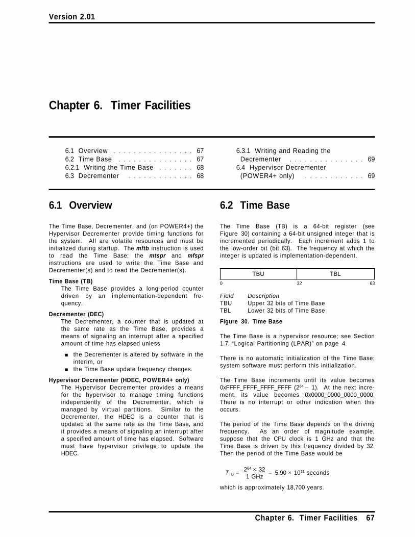
Version 2.01
Chapter 6. Timer Facilities
6.1 Overview . . . . . . . . . . . . . . . . 676.2 Time Base . . . . . . . . . . . . . . . 676.2.1 Writing the Time Base . . . . . . . 686.3 Decrementer . . . . . . . . . . . . . 68
6.3.1 Writing and Reading theDecrementer . . . . . . . . . . . . . . . 69
6.4 Hypervisor Decrementer(POWER4+ only) . . . . . . . . . . . . 69
6.1 Overview
The Time Base, Decrementer, and (on POWER4+) theHypervisor Decrementer provide timing functions forthe system. All are volatile resources and must beinitialized during startup. The mftb instruction is usedto read the Time Base; the mtspr and mfsprinstructions are used to write the Time Base andDecrementer(s) and to read the Decrementer(s).
Time Base (TB)The Time Base provides a long-period counterdriven by an implementation-dependent fre-quency.
Decrementer (DEC)The Decrementer, a counter that is updated atthe same rate as the Time Base, provides ameans of signaling an interrupt after a specifiedamount of time has elapsed unless
■ the Decrementer is altered by software in theinterim, or
■ the Time Base update frequency changes.
Hypervisor Decrementer (HDEC, POWER4+ only)The Hypervisor Decrementer provides a meansfor the hypervisor to manage timing functionsindependently of the Decrementer, which ismanaged by virtual partitions. Similar to theDecrementer, the HDEC is a counter that isupdated at the same rate as the Time Base, andit provides a means of signaling an interrupt aftera specified amount of time has elapsed. Softwaremust have hypervisor privilege to update theHDEC.
6.2 Time Base
The Time Base (TB) is a 64-bit register (seeFigure 30) containing a 64-bit unsigned integer that isincremented periodically. Each increment adds 1 tothe low-order bit (bit 63). The frequency at which theinteger is updated is implementation-dependent.
TBU TBL
0 32 63
Field DescriptionTBU Upper 32 bits of Time BaseTBL Lower 32 bits of Time Base
Figure 30. Time Base
The Time Base is a hypervisor resource; see Section1.7, “Logical Partitioning (LPAR)” on page 4.
There is no automatic initialization of the Time Base;system software must perform this initialization.
The Time Base increments until its value becomes0xFFFF_FFFF_FFFF_FFFF (264 − 1). At the next incre-ment, its value becomes 0x0000_0000_0000_0000.There is no interrupt or other indication when thisoccurs.
The period of the Time Base depends on the drivingfrequency. As an order of magnitude example,suppose that the CPU clock is 1 GHz and that theTime Base is driven by this frequency divided by 32.Then the period of the Time Base would be
TTB = 264 × 321 GHz
= 5.90 × 10¹¹ seconds
which is approximately 18,700 years.
Chapter 6. Timer Facilities 67

Version 2.01
The Time Base must be implemented such that thefollowing requirements are satisfied.
1. Loading a GPR from the Time Base shall have noeffect on the accuracy of the Time Base.
2. Storing a GPR to the Time Base shall replace thevalue in the Time Base with the value in the GPR.
The PowerPC Architecture does not specify a relation-ship between the frequency at which the Time Base isupdated and other frequencies, such as the CPU clockor bus clock in a PowerPC system. The Time Baseupdate frequency is not required to be constant.What is required, so that system software can keeptime of day and operate interval timers, is one of thefollowing.
■ The system provides an (implementa-tion-dependent) interrupt to software wheneverthe update frequency of the Time Base changes,and a means to determine what the currentupdate frequency is.
■ The update frequency of the Time Base is underthe control of the system software.
Implementations must provide a means for either pre-venting the Time Base from incrementing or pre-venting it from being read in problem state(MSRPR=1) . If the means is under software control, itmust be accessible only in hypervisor state(MSRHV PR = 0b10). There must be a method forgetting all processors' Time Bases to start incre-menting with values that are identical or almost iden-tical in all processors.
Programming Note
If the hypervisor initializes the Time Base onpower-on to some reasonable value and theupdate frequency of the Time Base is constant,the Time Base can be used as a source of valuesthat increase at a constant rate, such as for timestamps in trace entries.
Even if the update frequency is not constant,values read from the Time Base aremonotonically increasing (except when the TimeBase wraps from 264− 1 to 0). If a trace entry isrecorded each time the update frequencychanges, the sequence of Time Base values canbe post-processed to become actual time values.
Successive readings of the Time Base may returnidentical values.
See the description of the Time Base in Book II,PowerPC Virtual Environment Architecture forways to compute time of day in POSIX formatfrom the Time Base.
6.2.1 Writing the Time Base
Writing the Time Base is privileged, and can be doneonly in hypervisor state. Reading the Time Base isnot privileged; it is discussed in Book II, PowerPCVirtual Environment Architecture.
It is not possible to write the entire 64-bit Time Baseusing a single instruction. The mttbl and mttbuextended mnemonics write the lower and upperhalves of the Time Base (TBL and TBU), respectively,preserving the other half. These are extended mne-monics for the mtspr instruction; see page 83.
The Time Base can be written by a sequence such as:
lwz Rx,upper # load 64-bit value forlwz Ry,lower # TB into Rx and Ryli Rz,0mttbl Rz # force TBL to 0mttbu Rx # set TBUmttbl Ry # set TBL
Provided that no interrupts occur while the last threeinstructions are being executed, loading 0 into TBLprevents the possibility of a carry from TBL to TBUwhile the Time Base is being initialized.
Programming Note
The instructions for writing the Time Base aremode-independent. Thus code written to set theTime Base will work correctly in either 64-bit or32-bit mode.
6.3 Decrementer
The Decrementer (DEC) is a 32-bit decrementingcounter that provides a mechanism for causing aDecrementer interrupt after a programmable delay.The contents of the Decrementer are treated as asigned integer.
DEC
0 31
Figure 31. Decrementer
The Decrementer is driven by the same frequency asthe Time Base. The period of the Decrementer willdepend on the driving frequency, but if the samevalues are used as given above for the Time Base(see Section 6.2), and if the Time Base update fre-quency is constant, the period would be
TDEC = 232 × 321 GHz
= 137 seconds.
68 PowerPC Operating Environment Architecture

Version 2.01
The Decrementer counts down. On POWER4, aDecrementer exception occurs when DEC0 changesfrom 0 to 1. On POWER4+, operation is as follows.
The exception effects of the Decrementer are said tobe consistent with the contents of the Decrementer ifone of the following statements is true.
■ DEC0= 0 and a Decrementer exception does notexist.
■ DEC0= 1 and a Decrementer exception exists.
If DEC0= 0 , a context synchronizing instruction orevent ensures that the exception effects of theDecrementer are consistent with the contents of theDecrementer. Otherwise, when the contents of DEC0change, the exception effects of the Decrementerbecome consistent with the new contents of theDecrementer reasonably soon after the change.
The preceding paragraph applies regardless ofwhether the change in the contents of DEC0 is theresult of decrementation of the Decrementer by theprocessor or of modification of the Decrementercaused by execution of an mtspr instruction.
On both POWER4 and POWER4+, the Decrementermust be implemented such that requirements 1 to 3below are satisfied. On POWER4, requirements 4 and5 must also be satisfied.
1. The operation of the Time Base and theDecrementer is coherent, i.e., the counters aredriven by the same fundamental time base.
2. Loading a GPR from the Decrementer shall haveno effect on the accuracy of the Decrementer.
3. Storing a GPR to the Decrementer shall replacethe value in the Decrementer with the value inthe GPR.
4. Whenever bit 0 of the Decrementer changes from0 to 1, an interrupt request is signaled. If mul-tiple Decrementer interrupt requests are receivedbefore the first can be reported, only one inter-rupt is reported. The occurrence of aDecrementer interrupt cancels the request.
5. If the Decrementer is altered by software and thecontents of bit 0 are changed from 0 to 1, aninterrupt request is signaled.
Programming Note
In systems that change the Time Base update fre-quency for purposes such as power management,the Decrementer input frequency will also change.Software must be aware of this in order to setinterval timers.
6.3.1 Writing and Reading theDecrementer
The contents of the Decrementer can be read orwritten using the mfspr and mtspr instructions, bothof which are privileged when they refer to theDecrementer. Using an extended mnemonic (seepage 83), the Decrementer can be written from GPRRx using:
mtdec Rx
Programming Note
On POWER4, if the execution of the mtdec instruc-tion causes bit 0 of the Decrementer to changefrom 0 to 1, an interrupt request is signaled.
The Decrementer can be read into GPR Rx using:
mfdec Rx
Copying the Decrementer to a GPR has no effect onthe Decrementer contents or on the interrupt mech-anism.
6.4 Hypervisor Decrementer(POWER4+ only)
The Hypervisor Decrementer (HDEC) is a 32-bit decre-menting counter that provides a mechanism forcausing a Hypervisor Decrementer interrupt after aprogrammable delay. The contents of theDecrementer are treated as a signed integer.
HDEC
0 31
Figure 32. Hypervisor Decrementer
The Hypervisor Decrementer is a hypervisorresource; see Section 1.7, “Logical Partitioning(LPAR)” on page 4.
The Hypervisor Decrementer is driven by the samefrequency as the Time Base. The period of theHypervisor Decrementer will depend on the drivingfrequency, but if the same values are used as givenabove for the Time Base (see Section 6.2), and if theTime Base update frequency is constant, the periodwould be
TDEC = 232 × 321 GHz
= 137 seconds.
The exception effects of the Hypervisor Decrementerare said to be consistent with the contents of theHypervisor Decrementer if one of the following state-ments is true.
Chapter 6. Timer Facilities 69

Version 2.01
■ HDEC0= 0 and a Hypervisor Decrementer excep-tion does not exist.
■ HDEC0= 1 and a Hypervisor Decrementer excep-tion exists.
If HDEC0= 0 , a context synchronizing instruction orevent ensures that the exception effects of theHypervisor Decrementer are consistent with the con-tents of the Hypervisor Decrementer. Otherwise,when the contents of HDEC0 change, the exceptioneffects of the Hypervisor Decrementer become con-sistent with the new contents of the HypervisorDecrementer reasonably soon after the change.
The preceding paragraph applies regardless ofwhether the change in the contents of HDEC0 is theresult of decrementation of the HypervisorDecrementer by the processor or of modification ofthe Hypervisor Decrementer caused by execution ofan mtspr instruction.
The Hypervisor Decrementer must be implementedsuch that the following requirements are satisfied.
1. The operation of the Time Base and theHypervisor Decrementer is coherent, i.e., thecounters are driven by the same fundamentaltime base.
2. Loading a GPR from the Hypervisor Decrementershall have no effect on the accuracy of theHypervisor Decrementer.
3. Storing a GPR to the Hypervisor Decrementershall replace the value in the HypervisorDecrementer with the value in the GPR.
Programming Note
In systems that change the Time Base update fre-quency for purposes such as power management,the Hypervisor Decrementer update frequency willalso change. Software must be aware of this inorder to set interval timers.
70 PowerPC Operating Environment Architecture

Version 2.01
Chapter 7. Synchronization Requirements for ContextAlterations
Changing the contents of certain System Registersand of SLB entries and Page Table Entries, and invali-dating SLB and TLB entries, can have the side effectof altering the context in which data addresses andinstruction addresses are interpreted, and in whichinstructions are executed and data accesses are per-formed. For example, changing MSRIR from 0 to 1has the side effect of enabling translation of instruc-tion addresses. These side effects need not occur inprogram order, and therefore may require explicitsynchronization by software. (Program order isdefined in Book II, PowerPC Virtual EnvironmentArchitecture.)
An instruction that alters the context in which dataaddresses or instruction addresses are interpreted, orin which instructions are executed or data accessesare performed, is called a context-altering instruction.This chapter covers all the context-alteringinstructions. The software synchronization requiredfor them is shown in Table 1 (for data access) andTable 2 (for instruction fetch and execution).
The notation “CSI” in the tables means any contextsynchronizing instruction (e.g., sc, isync, or rfid). Acontext synchronizing interrupt (i.e., any interruptexcept non-recoverable System Reset or non-recoverable Machine Check) can be used instead of acontext synchronizing instruction. If it is, phrases like“ the synchronizing instruction”, below, should beinterpreted as meaning the instruction at which theinterrupt occurs. If no software synchronization isrequired before (after) a context-altering instruction,“ the synchronizing instruction before (after) thecontext-altering instruction” should be interpreted asmeaning the context-altering instruction itself.
The synchronizing instruction before the context-altering instruction ensures that all instructions up to
and including that synchronizing instruction arefetched and executed in the context that existedbefore the alteration. The synchronizing instructionafter the context-altering instruction ensures that allinstructions after that synchronizing instruction arefetched and executed in the context established bythe alteration. Instructions after the first synchro-nizing instruction, up to and including the second syn-chronizing instruction, may be fetched or executed ineither context.
If a sequence of instructions contains context-alteringinstructions and contains no instructions that areaffected by any of the context alterations, no softwaresynchronization is required within the sequence.
Programming Note
Sometimes advantage can be taken of the factthat certain events, such as interrupts, andcertain instructions that occur naturally in theprogram, such as the rfid that returns from aninterrupt handler, provide the required synchroni-zation.
No software synchronization is required before orafter a context-altering instruction that is also contextsynchronizing (e.g., rfid, mtmsr[ d] with L=0) , exceptperhaps when altering the LE bit (see the tables). Nosoftware synchronization is required before most ofthe other alterations shown in Table 2, because allinstructions preceding the context-altering instructionare fetched and decoded before the context-alteringinstruction is executed (the processor must determinewhether any of these preceding instructions arecontext synchronizing).
Unless otherwise stated, the material in this chapterassumes a uniprocessor environment.
Chapter 7. Synchronization Requirements for Context Alterations 71

Version 2.01
Table 1. Synchronization requirements for dataaccess
Notes:
Table 2. Synchronization requirements for instructionfetch and/or execution
Instruction orEvent
RequiredBefore
RequiredAfter
Notes Instruction orEvent
RequiredBefore
RequiredAfter
Notes
interrupt none none interrupt none nonerfid none none rfid none nonesc none none sc none noneTrap none none Trap none nonemtmsrd (SF) none none 3 mtmsrd (SF) none none 3, 10mtmsr[ d] (ILE) none none 3 mtmsr[ d] (ILE) none none 3mtmsr[ d] (PR) none none 3 mtmsr[ d] (EE) none none 2, 3mtmsr[ d] (DR) none none 3 mtmsr[ d] (PR) none none 3, 11mtmsr[ d] (LE) — — 1, 3 mtmsr[ d] (FP) none none 3mtsr[ in] CSI CSI mtmsr[ d] (FE0,FE1) none none 3mtspr (ACCR) CSI CSI mtmsr[ d] (SE, BE) none none 3mtspr (SDR1) ptesync CSI 5, 6 mtmsr[ d] (IR) none none 3, 11mtspr (DABR) — — 4 mtmsr[ d] (RI) none none 3mtspr (EAR) CSI CSI mtmsr[ d] (LE) — — 1, 3slbie CSI CSI mtsr[ in] none CSI 11slbia CSI CSI mtspr (SDR1) ptesync CSI 5, 6slbmte CSI CSI 13 mtspr (DEC) none none 12tlbie CSI CSI 7, 9 mtspr (HDEC) none none 12tlbiel CSI ptesync 7, 9 mtspr (LPIDR) CSI CSI 9, 14tlbia CSI CSI 7 mtspr (CTRL) none noneStore(PTE) none { ptesync, CSI} 8, 9 slbie none CSI
slbia none CSIslbmte none CSI 11, 13tlbie none CSI 7, 9tlbiel none CSI 7, 9tlbia none CSI 7Store(PTE) none { ptesync, CSI} 8, 9
1. Synchronization requirements for changing fromone Endian mode to the other using the mtmsr[ d]instruction are implementation-dependent, andare specified in the Book IV, PowerPC Implemen-tation Features document for the implementation.
2. The effect of changing the EE bit is immediate,even if the mtmsr[ d] instruction is not contextsynchronizing (i.e., even if L=1) .
■ If an mtmsr[ d] instruction sets the EE bit to0, neither an External interrupt nor aDecrementer interrupt occurs after themtmsr[ d] is executed.
■ If an mtmsr[ d] instruction changes the EE bitfrom 0 to 1 when an External, Decrementer,or higher priority exception exists, the corre-sponding interrupt occurs immediately afterthe mtmsr[ d] is executed, and before thenext instruction is executed in the programthat set EE to 1.
3. For software that will run on processors thatcomply with versions of the architecture thatprecede Version 2.01, a context synchronizinginstruction is required after the mtmsr[ d] instruc-tion; see the first Programming Note in the
descriptions of these instructions on pages 19and 78.
4. Synchronization requirements for changing theData Address Breakpoint Register are implemen-tation-dependent, and are specified in the BookIV, PowerPC Implementation Features documentfor the implementation.
5. SDR1 must not be altered when MSRDR= 1 orMSRIR= 1 ; if it is, the results are undefined.
6. A ptesync instruction is required before the mtsprinstruction because (a) SDR1 identifies the PageTable and thereby the location of Reference andChange bits, and (b) on some implementations,use of SDR1 to update Reference and Changebits may be independent of translating the virtualaddress. (For example, an implementation mightidentify the PTE in which to update the Referenceand Change bits in terms of its offset in the PageTable, instead of its real address, and then addthe Page Table address from SDR1 to the offsetto determine the real address at which to updatethe bits.) To ensure that Reference and Changebits are updated in the correct Page Table, SDR1must not be altered until all Reference andChange bits are updated in the correct Page
72 PowerPC Operating Environment Architecture

Version 2.01
Table, SDR1 must not be altered until all Refer-ence and Change bit updates associated withaddress translations that were performed, by theprocessor executing the mtspr instruction, beforethe mtspr instruction is executed have been per-formed with respect to that processor. A ptesyncinstruction guarantees this synchronization ofReference and Change bit updates, while neithera context synchronizing operation nor the instruc-tion fetching mechanism does so.
7. For data accesses, the context synchronizinginstruction before the tlbie, tlbiel, or tlbia instruc-tion ensures that all preceding instructions thataccess data storage have completed to a point atwhich they have reported all exceptions they willcause.
The context synchronizing instruction after thetlbie, tlbiel, or tlbia instruction ensures thatstorage accesses associated with instructions fol-lowing the context synchronizing instruction willnot use the TLB entry(s) being invalidated.
(If it is necessary to order storage accesses asso-ciated with preceding instructions, or Referenceand Change bit updates associated with pre-ceding address translations, with respect to sub-sequent data accesses, a ptesync instructionmust also be used, either before or after the tlbie,tlbiel, or tlbia instruction. These effects of theptesync instruction are described in the last para-graph of Note 8.)
8. The notation “ { ptesync,CSI}” denotes an instruc-tion sequence. Other instructions may be inter-leaved with this sequence, but these instructionsmust appear in the order shown.
No software synchronization is required beforethe Store instruction because (a) stores are notperformed out-of-order and (b) address trans-lations associated with instructions preceding theStore instruction are not performed again afterthe store has been performed (see Section 4.2.4).These properties ensure that all address trans-lations associated with instructions preceding theStore instruction will be performed using the oldcontents of the PTE.
The ptesync instruction after the Store instructionensures that all searches of the Page Table thatare performed after the ptesync instruction com-pletes will use the value stored (or a value storedsubsequently). The context synchronizing instruc-tion after the ptesync instruction ensures that anyaddress translations associated with instructionsfollowing the context synchronizing instructionthat were performed using the old contents of thePTE will be discarded, with the result that theseaddress translations will be performed again and,if there is no corresponding TLB entry, will usethe value stored (or a value stored subsequently).
The ptesync instruction also ensures that allstorage accesses associated with instructionspreceding the ptesync instruction, and all Refer-ence and Change bit updates associated withaddress translations that were performed, by theprocessor executing the ptesync instruction,before the ptesync instruction is executed, will beperformed with respect to any processor ormechanism, to the extent required by the associ-ated Memory Coherence Required attributes,before any data accesses caused by instructionsfollowing the ptesync instruction are performedwith respect to that processor or mechanism.
9. There are additional software synchronizationrequirements for the tlbie instruction in multi-processor environments; see Section 4.12, “PageTable Update Synchronization Requirements” onpage 48.
Section 4.12 also gives examples of using tlbie,Store, and related instructions to maintain thePage Table, in both multiprocessor anduniprocessor environments.
Programming Note
In a multiprocessor system, if softwarelocking is used to help ensure that therequirements described in Section 4.12 aresatisfied, the isync instruction near the end ofthe lock acquisition sequence (see the sectionentitled “Acquire Lock and Import SharedStorage” in Book II, PowerPC Virtual Environ-ment Architecture) may naturally provide thecontext synchronization that is requiredbefore the alteration.
10. The alteration must not cause an implicit branchin effective address space. Thus, when changingMSRSF from 1 to 0, the mtmsrd instruction musthave an effective address that is less than232 − 4. Furthermore, when changing MSRSF from0 to 1, the mtmsrd instruction must not be ateffective address 232 − 4 (see Section 4.2.2.2 onpage 23).
11. The alteration must not cause an implicit branchin real address space. Thus the real address ofthe context-altering instruction and of each sub-sequent instruction, up to and including the nextcontext synchronizing instruction, must be inde-pendent of whether the alteration has takeneffect.
12. The elapsed time between the contents of theDecrementer or Hypervisor Decrementerbecoming negative and the signaling of the corre-sponding exception is not defined.
13. If an slbmte instruction alters the mapping, orassociated attributes, of a currently mappedESID, the slbmte must be preceded by an slbie(or slbia) instruction that invalidates the existingtranslation. This applies even if the corre-
Chapter 7. Synchronization Requirements for Context Alterations 73
Version 2.01
sponding entry is no longer in the SLB (the trans-lation may still be in implementation-specificaddress translation lookaside information). Nosoftware synchronization is needed between theslbie and the slbmte, regardless of whether theindex of the SLB entry (if any) containing thecurrent translation is the same as the SLB indexspecified by the slbmte.
No slbie (or slbia) is needed if the slbmte instruc-tion replaces a valid SLB entry with a mapping ofa different ESID (e.g., to satisfy an SLB miss).However, the slbie is needed later if and when
the translation that was contained in the replacedSLB entry is to be invalidated.
14. The context synchronizing instruction before themtspr instruction ensures that the LPIDR is notaltered out-of-order. (Out-of-order alteration ofthe LPIDR could permit the requirementsdescribed in Section 4.12.1 to be violated. Forthe same reason, such a context synchronizinginstruction may be needed even if the new LPIDvalue is equal to the old LPID value.)
See also Section 1.7, “Logical Partitioning(LPAR)” on page 4 regarding moving a processorfrom one partition to another.
74 PowerPC Operating Environment Architecture
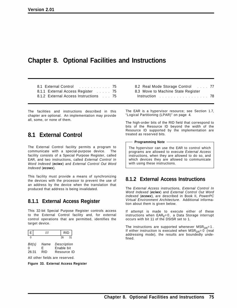
Version 2.01
Chapter 8. Optional Facilities and Instructions
8.1 External Control . . . . . . . . . . . 758.1.1 External Access Register . . . . . 758.1.2 External Access Instructions . . . 75
8.2 Real Mode Storage Control . . . . 778.3 Move to Machine State Register
Instruction . . . . . . . . . . . . . . . . . 78
The facilities and instructions described in thischapter are optional. An implementation may provideall, some, or none of them.
8.1 External Control
The External Control facility permits a program tocommunicate with a special-purpose device. Thefacility consists of a Special Purpose Register, calledEAR, and two instructions, called External Control InWord Indexed (eciwx) and External Control Out WordIndexed (ecowx).
This facility must provide a means of synchronizingthe devices with the processor to prevent the use ofan address by the device when the translation thatproduced that address is being invalidated.
8.1.1 External Access Register
This 32-bit Special Purpose Register controls accessto the External Control facility and, for externalcontrol operations that are permitted, identifies thetarget device.
E /// RID0 26 31
Bit(s) Name Description0 E Enable bit26:31 RID Resource ID
All other fields are reserved.
Figure 33. External Access Register
The EAR is a hypervisor resource; see Section 1.7,“Logical Partitioning (LPAR)” on page 4.
The high-order bits of the RID field that correspond tobits of the Resource ID beyond the width of theResource ID supported by the implementation aretreated as reserved bits.
Programming Note
The hypervisor can use the EAR to control whichprograms are allowed to execute External Accessinstructions, when they are allowed to do so, andwhich devices they are allowed to communicatewith using these instructions.
8.1.2 External Access Instructions
The External Access instructions, External Control InWord Indexed (eciwx) and External Control Out WordIndexed (ecowx), are described in Book II, PowerPCVirtual Environment Architecture. Additional informa-tion about them is given below.
If attempt is made to execute either of theseinstructions when EARE= 0 , a Data Storage interruptoccurs with bit 11 of the DSISR set to 1.
The instructions are supported whenever MSRDR= 1 .If either instruction is executed when MSRDR= 0 (realaddressing mode), the results are boundedly unde-fined.
Chapter 8. Optional Facilities and Instructions 75

Version 2.01
76 PowerPC Operating Environment Architecture

Version 2.01
8.2 Real Mode Storage Control
The Real Mode Storage Control facility provides ameans of specifying portions of real storage that aretreated as non-Guarded in hypervisor real addressingmode (MSRHV PR=0b10, and MSRIR= 0 or MSRDR= 0 ,as appropriate for the type of access). The remainingportions are treated as Guarded in hypervisor realaddressing mode (as is all of storage on implementa-tions that do not provide this means). The means is ahypervisor resource (see Section 1.7, “Logical Parti-tioning (LPAR)” on page 4), and may also be system-specific.
If the Real Mode Caching Inhibited (RMI) bit is set to1, it is undefined whether a given data access to astorage location that is treated as non-Guarded inhypervisor real addressing mode is treated asCaching Inhibited or as not Caching Inhibited. If theaccess is treated as Caching Inhibited and is per-formed out-of-order, the access cannot cause aMachine Check or Checkstop to occur out-of-orderdue to violation of the requirements given in Section4.8.2, “Altering the Storage Control Bits” on page 36for changing the value of the effective I bit. (Recallthat software must ensure that RMI = 0 when theprocessor is not in hypervisor real addressing mode;see Section 4.2.6.2, “Storage Control Attributes forReal Addressing Mode and for Implicit StorageAccesses” on page 26.)
The facility does not apply to implicit accesses to thePage Table by the processor in performing addresstranslation or in recording reference and changeinformation. These accesses are performed asdescribed in Section 4.2.6.2 on page 26.
Programming Note
The preceding capability can be used to improvethe performance of hypervisor software that runsin hypervisor real addressing mode, by causingaccesses to instructions and data that occupywell-behaved storage to be treated as non-Guarded. See also the second paragraph of theProgramming Note in Section 4.2.6.2.
If RMI=1, the statement in Section 4.2.4, “Per-forming Operations Out-of-Order” on page 23,that non-Guarded storage locations may befetched out-of-order into a cache only if they couldbe fetched into that cache by in-order executiondoes not preclude the out-of-order fetching intothe data cache of storage locations that aretreated as non-Guarded in hypervisor realaddressing mode, because the effective RMIvalue that could be used for an in-order dataaccess to such a storage location is undefined andhence could be 0.
Chapter 8. Optional Facilities and Instructions 77

Version 2.01
8.3 Move to Machine State Register Instruction
Move To Machine State Register X-form
mtmsr RS,L
31 RS /// L /// 146 /
0 6 11 15 16 21 31
if L = 0 thenMSR48 ←(RS)48 (POWER4 only)MSR48 ←(RS)48 | (RS)49 (POWER4+ only)MSR58 ← (RS)58 | (RS)49MSR59 ← (RS)59 | (RS)49MSR32:47 49:50 52:57 60:63 ← (RS)32:47 49:50 52:57 60:63
elseMSR48 62 ← (RS)48 62
The MSR is set based on the contents of register RSand of the L field.
L=0 :On POWER4, bit 48 of register RS is placed intoMSR48. On POWER4+, the result of ORing bits 48and 49 of register RS is placed into MSR48. Theresult of ORing bits 58 and 49 of register RS isplaced into MSR58. The result of ORing bits 59and 49 of register RS is placed into MSR59. Bits32:47, 49:50, 52:57, and 60:63 of register RS areplaced into the corresponding bits of the MSR.
L=1 :Bits 48 and 62 of register RS are placed into thecorresponding bits of the MSR. The remaining bitsof the MSR are unchanged.
This instruction is privileged.
If L = 0 this instruction is context synchronizing exceptwith respect to alterations to the LE bit; seeChapter 7, “Synchronization Requirements forContext Alterations” on page 71. If L = 1 this instruc-tion is execution synchronizing; in addition, the alter-ations of the EE and RI bits take effect as soon as theinstruction completes. Thus if MSREE= 0 and anExternal or Decrementer exception is pending, exe-cuting an mtmsr instruction that sets MSREE to 1 willcause the External or Decrementer interrupt to occurbefore the next instruction is executed, if no higherpriority exception exists (see Section 5.8, “InterruptPriorities” on page 65).
Special Registers Altered:MSR
Except in the mtmsr instruction description in thissection, references to “ mtmsr” in Books I - III implyeither L value unless otherwise stated or obviousfrom context (e.g., a reference to an mtmsr instructionthat modifies an MSR bit other than the EE or RI bitimplies L=0) .
Programming Note
Warning: The first Programming Note in themtmsrd instruction description applies to mtmsras well as to mtmsrd. Therefore software thatuses mtmsr and will run on such processors mustobey the rules given in that Programming Note.
Programming Note
If this instruction sets MSRPR to 1, it also setsMSREE (POWER4+ only), MSRIR, and MSRDR to 1.
This instruction does not alter MSRME. (Thisinstruction does not alter MSRHV because it doesnot alter any of the high-order 32 bits of the MSR.)
If the only MSR bits to be altered are MSREE RI, toobtain the best performance L = 1 should be used.
Programming Note
For a discussion of software synchronizationrequirements when altering certain MSR bits, seeChapter 7.
Programming Note
mtmsr serves as both a basic and an extendedmnemonic. The Assembler will recognize anmtmsr mnemonic with two operands as the basicform, and an mtmsr mnemonic with one operandas the extended form. In the extended form the Loperand is omitted and assumed to be 0.
Programming Note
There is no need for an analogous version of themfmsr instruction, because the existing instructioncopies the entire contents of the MSR to theselected GPR.
78 PowerPC Operating Environment Architecture

Version 2.01
Chapter 9. Optional Facilities and Instructions that are beingPhased Out of the Architecture
9.1 Bridge to SLB Architecture . . . . . 799.1.1 Address Space Register . . . . . 79
9.1.2 Segment Register ManipulationInstructions . . . . . . . . . . . . . . . . 80
The facilities and instructions described in thischapter are optional. An implementation may provideall, some, or none of them.
Warning: These facilities and instructions are beingphased out of the architecture.
The facilities and instructions described in thischapter are generally not mentioned elsewhere inBooks I − III. Any conflict between this chapter andother parts of the Books is deemed to be resolved infavor of this chapter.
9.1 Bridge to SLB Architecture
The facility described in this section can be used toease the transition to the current PowerPC software-managed Segment Lookaside Buffer (SLB) architec-ture, from either the Segment Register architectureprovided by 32-bit PowerPC implementations or thehardware-accessed Segment Table architecture pro-vided by 64-bit PowerPC implementations and byearlier PowerPC implementations.
The facility permits the operating system to continueto use the 32-bit PowerPC implementation's SegmentRegister Manipulation instructions, and to continue touse the Address Space Register (ASR).
Programming Note
Warning: This facility is being phased out of thearchitecture. It is likely not to be supported onfuture implementations. New programs shouldnot use it.
9.1.1 Address Space Register
The ASR is a 64-bit Special Purpose Register pro-vided for operating system use.
ASR
0 63
Figure 34. Address Space Register
Programming Note
The ASR can be used to point to a SegmentTable.
On earlier PowerPC implementations and on 64-bitPowerPC implementations, bits 0:51 of the ASRcontained the high-order 52 bits of the 64-bit realaddress of the Segment Table, and bit 63 of theASR indicated whether the specified SegmentTable should (bit 63 = 1) or should not (bit 63 =0) be searched by the processor when doingaddress translation.
Chapter 9. Optional Facilities and Instructions that are being Phased Out 79

Version 2.01
9.1.2 Segment Register Manipulation Instructions
The instructions described in this section — mtsr,mtsrin, mfsr, and mfsrin — allow software to associateeffective segments 0 through 15 with any of virtualsegments 0 through 227− 1. SLB entries 0:15 serve asvirtual Segment Registers, with SLB entry i used toemulate Segment Register i. The mtsr and mtsrininstructions move 32 bits from a selected GPR to aselected SLB entry. The mfsr and mfsrin instructionsmove 32 bits from a selected SLB entry to a selectedGPR.
The contents of the GPRs used by the instructionsdescribed in this section are shown in Figure 35.Fields shown as zeros must be zero for the Move ToSegment Register instructions. Fields shown ashyphens are ignored. Fields shown as periods areignored by the Move To Segment Registerinstructions and set to zero by the Move FromSegment Register instructions. Fields shown ascolons are ignored by the Move To Segment Registerinstructions and set to undefined values by the MoveFrom Segment Register instructions.
RS/RT
: : : . KsKpN 0 VSID25:51
0 31 33 35 37 63
RB
- - - ESID - - -
0 32 35 63
Figure 35. GPR contents for mtsr, mtsrin, mfsr, andmfsrin
Programming Note
The “Segment Register” format used by theinstructions described in this section correspondsto the low-order 32 bits of RS and RT shown inthe figure. This format is essentially the same asthat for the Segment Registers of 32-bit PowerPCimplementations. The only differences are the fol-lowing.
■ Bit 36 corresponds to a reserved bit inSegment Registers. Software must supply 0for the bit because it corresponds to the L bitin SLB entries, and large pages are not sup-ported for SLB entries created by the MoveTo Segment Register instructions.
■ VSID bits 25:27 correspond to reserved bits inSegment Registers. Software can use theseextra VSID bits to create VSIDs that arelarger than those supported by the SegmentRegister Manipulation instructions of 32-bitPowerPC implementations.
Bit 32 of RS and RT corresponds to the T (direct-store) bit of early 32-bit PowerPC implementa-tions. No corresponding bit exists in SLB entries.
Programming Note
The Programming Note in the introduction toSection 4.11.3.1, “SLB Management Instructions”on page 41 applies also to the Segment RegisterManipulation instructions described in thissection, and to any combination of the instructionsdescribed in the two sections, except as specifiedbelow for mfsr and mfsrin.
The requirement that the SLB contain at most oneentry that translates a given effective address(see Section 4.4.1, “Segment Lookaside Buffer(SLB)” on page 29) applies to SLB entries createdby mtsr and mtsrin. This requirement is satisfiednaturally if only mtsr and mtsrin are used tocreate SLB entries for a given ESID, because forthese instructions the association between SLBentries and ESID values is fixed (SLB entry i isused for ESID i). However, care must be taken ifslbmte is also used to create SLB entries for theESID, because for slbmte the association betweenSLB entries and ESID values is specified by soft-ware.
80 PowerPC Operating Environment Architecture

Version 2.01
Move To Segment Register X-form
mtsr SR,RS
31 RS / SR /// 210 /
0 6 11 12 16 21 31
The SLB entry specified by SR is loaded from registerRS, as follows.
SLBE Bit(s) Set to SLB Field(s)0:31 0x0000_0000 ESID0:3132:35 SR ESID32:3536 0b1 V37:61 0x00_0000| |0b0 VSID0:2462:88 (RS)37:63 VSID25:5189:91 (RS)33:35 KsKpN92 (RS)36 L ((RS)36 must be 0b0)93 0b0 C
MSRSF must be 0 when this instruction is executed;otherwise the results are boundedly undefined.
This instruction is privileged.
Special Registers Altered:None
Move To Segment Register IndirectX-form
mtsrin RS,RB
[POWER mnemonic: mtsri]
31 RS /// RB 242 /
0 6 11 16 21 31
The SLB entry specified by (RB)32:35 is loaded fromregister RS, as follows.
SLBE Bit(s) Set to SLB Field(s)0:31 0x0000_0000 ESID0:3132:35 (RB)32:35 ESID32:3536 0b1 V37:61 0x00_0000| |0b0 VSID0:2462:88 (RS)37:63 VSID25:5189:91 (RS)33:35 KsKpN92 (RS)36 L ((RS)36 must be 0b0)93 0b0 C
MSRSF must be 0 when this instruction is executed;otherwise the results are boundedly undefined.
This instruction is privileged.
Special Registers Altered:None
Chapter 9. Optional Facilities and Instructions that are being Phased Out 81

Version 2.01
Move From Segment Register X-form
mfsr RT,SR
31 RT / SR /// 595 /
0 6 11 12 16 21 31
The contents of the low-order 27 bits of the VSID field,and the contents of the Ks, Kp, N, and L fields, of theSLB entry specified by SR are placed into register RT,as follows.
SLBE Bit(s) Copied to SLB Field(s)62:88 RT37:63 VSID25:5189:91 RT33:35 KsKpN92 RT36 L (SLBEL must be 0b0)
RT32 is set to 0. The contents of RT0:31 are undefined.
MSRSF must be 0 when this instruction is executed;otherwise the results are boundedly undefined.
This instruction must be used only to read an SLBentry that was, or could have been, created by mtsror mtsrin and has not subsequently been invalidated(i.e., an SLB entry in which ESID< 16, V=1 , VSID< 227,L=0 , and C=0). Otherwise the contents of registerRT are undefined.
This instruction is privileged.
Special Registers Altered:None
Move From Segment Register IndirectX-form
mfsrin RT,RB
31 RT /// RB 659 /
0 6 11 16 21 31
The contents of the low-order 27 bits of the VSID field,and the contents of the Ks, Kp, N, and L fields, of theSLB entry specified by (RB)32:35 are placed into reg-ister RT, as follows.
SLBE Bit(s) Copied to SLB Field(s)62:88 RT37:63 VSID25:5189:91 RT33:35 KsKpN92 RT36 L (SLBEL must be 0b0)
RT32 is set to 0. The contents of RT0:31 are undefined.
MSRSF must be 0 when this instruction is executed;otherwise the results are boundedly undefined.
This instruction must be used only to read an SLBentry that was, or could have been, created by mtsror mtsrin and has not subsequently been invalidated(i.e., an SLB entry in which ESID< 16, V=1 , VSID< 227,L=0 , and C=0). Otherwise the contents of registerRT are undefined.
This instruction is privileged.
Special Registers Altered:None
82 PowerPC Operating Environment Architecture

Version 2.01
Appendix A. Assembler Extended Mnemonics
In order to make assembler language programs simpler to write and easier to understand, a set of extendedmnemonics and symbols is provided for certain instructions. This appendix defines extended mnemonics andsymbols related to instructions defined in Book III.
Assemblers should provide the extended mnemonics and symbols listed here, and may provide others.
A.1 Move To/From Special Purpose Register Mnemonics
This section defines extended mnemonics for the mtspr and mfspr instructions, including the Special Purpose Reg-isters (SPRs) defined in Book I and certain privileged SPRs, and for the Move From Time Base instruction definedin Book II.
The mtspr and mfspr instructions specify an SPR as a numeric operand; extended mnemonics are provided thatrepresent the SPR in the mnemonic rather than requiring it to be coded as an operand. Similar extended mne-monics are provided for the Move From Time Base instruction, which specifies the portion of the Time Base as anumeric operand.
Note: mftb serves as both a basic and an extended mnemonic. The Assembler will recognize an mftb mnemonicwith two operands as the basic form, and an mftb mnemonic with one operand as the extended form. In theextended form the TBR operand is omitted and assumed to be 268 (the value that corresponds to TB).
Table 3 (Page 1 of 2). Extended mnemonics for moving to/from an SPR
Special Purpose RegisterMove To SPR Move From SPR1
Extended Equivalent to Extended Equivalent to
Fixed-Point ExceptionRegister
mtxer Rx mtspr 1,Rx mfxer Rx mfspr Rx,1
Link Register mtlr Rx mtspr 8,Rx mflr Rx mfspr Rx,8
Count Register mtctr Rx mtspr 9,Rx mfctr Rx mfspr Rx,9
Data Storage InterruptStatus Register
mtdsisr Rx mtspr 18,Rx mfdsisr Rx mfspr Rx,18
Data Address Register mtdar Rx mtspr 19,Rx mfdar Rx mfspr Rx,19
Decrementer mtdec Rx mtspr 22,Rx mfdec Rx mfspr Rx,22
Storage DescriptionRegister 1
mtsdr1 Rx mtspr 25,Rx mfsdr1 Rx mfspr Rx,25
Save/Restore Register 0 mtsrr0 Rx mtspr 26,Rx mfsrr0 Rx mfspr Rx,26
Save/Restore Register 1 mtsrr1 Rx mtspr 27,Rx mfsrr1 Rx mfspr Rx,27
ACCR mtaccr Rx mtspr 29,Rx mfaccr Rx mfspr Rx,29
CTRL mtctrl Rx mtspr 152,Rx mfctrl Rx mfspr Rx,136
Special Purpose RegistersG0 through G3
mtsprg n,Rx mtspr 272+n,Rx mfsprg Rx,n mfspr Rx,272+n
Appendix A. Assembler Extended Mnemonics 83

Version 2.01
Table 3 (Page 2 of 2). Extended mnemonics for moving to/from an SPR
Special Purpose RegisterMove To SPR Move From SPR1
Extended Equivalent to Extended Equivalent to
Time Base [ Lower] mttbl Rx mtspr 284,Rx mftb Rx mftb Rx,268
Time Base Upper mttbu Rx mtspr 285,Rx mftbu Rx mftb Rx,269
Processor Version Register − − mfpvr Rx mfspr Rx,287
MMCRA mtmmcra Rx mtspr 786,Rx mfmmcra Rx mfspr Rx,770
PMC1 mtpmc1 Rx mtspr 787,Rx mfpmc1 Rx mfspr Rx,771
PMC2 mtpmc2 Rx mtspr 788,Rx mfpmc2 Rx mfspr Rx,772
PMC3 mtpmc3 Rx mtspr 789,Rx mfpmc3 Rx mfspr Rx,773
PMC4 mtpmc4 Rx mtspr 790,Rx mfpmc4 Rx mfspr Rx,774
PMC5 mtpmc5 Rx mtspr 791,Rx mfpmc5 Rx mfspr Rx,775
PMC6 mtpmc6 Rx mtspr 792,Rx mfpmc6 Rx mfspr Rx,776
PMC7 mtpmc7 Rx mtspr 793,Rx mfpmc7 Rx mfspr Rx,777
PMC8 mtpmc8 Rx mtspr 794,Rx mfpmc8 Rx mfspr Rx,778
MMCR0 mtmmcr0 Rx mtspr 795,Rx mfmmcr0 Rx mfspr Rx,779
MMCR1 mtmmcr1 Rx mtspr 798,Rx mfmmcr1 Rx mfspr Rx,782
Processor IdentificationRegister
− − mfpir Rx mfspr Rx,1023
1Except for mftb and mftbu.
Programming Note
The extended mnemonics in Table 3 for SPRsassociated with the Performance Monitor facilityare based on the definitions in Appendix E.
Other versions of Performance Monitor facilitiesused different sets of SPR numbers (all 32-bitPowerPC processors used a different set, andsome early PowerPC processors used yet a dif-ferent set).
84 PowerPC Operating Environment Architecture

Version 2.01
Appendix B. Cross-Reference for Changed POWERMnemonics
The following table lists the POWER instruction mne-monics that have been changed in the PowerPC Oper-ating Environment Architecture, sorted by POWERmnemonic.
To determine the PowerPC mnemonic for one of thesePOWER mnemonics, find the POWER mnemonic in thesecond column of the table: the remainder of the line
gives the PowerPC mnemonic and the page on whichthe instruction is described, as well as the instructionnames.
POWER mnemonics that have not changed are notlisted. POWER instruction names that are the same inPowerPC are not repeated: i.e., for these, the lastcolumn of the table is blank.
PagePOWER PowerPC
Mnemonic Instruction Mnemonic Instruction
81 mtsri Move To Segment Register Indirect mtsrin10 svca Supervisor Call sc System Call45 tlbi TLB Invalidate Entry tlbie
Appendix B. Cross-Reference for Changed POWER Mnemonics 85

Version 2.01
86 PowerPC Operating Environment Architecture

Version 2.01
Appendix C. New and Newly Optional Instructions
The following instructions in the PowerPC OperatingEnvironment Architecture are new; they are not in thePOWER Architecture. The tlbia, tlbsync, and mtmsrinstructions are optional. In addition, the mfsr, mfsrin,mtsr, and mtsrin instructions may optionally be pro-vided as part of a “bridge” facility as described inSection 9.1, “Bridge to SLB Architecture” on page 79.
mfsrin Move From Segment Register Indirectmtmsrd Move To Machine State Register
Doublewordrfid Return From Interrupt Doublewordslbia SLB Invalidate Allslbie SLB Invalidate Entryslbmfee SLB Move From Entry ESIDslbmfev SLB Move From Entry VSIDslbmte SLB Move To Entrytlbia TLB Invalidate Alltlbsync TLB Synchronize
Appendix C. New and Newly Optional Instructions 87

Version 2.01
88 PowerPC Operating Environment Architecture

Version 2.01
Appendix D. Interpretation of the DSISR as Set by anAlignment Interrupt
For most causes of Alignment interrupt, the interrupthandler will emulate the interrupting instruction. Todo this, it needs the following characteristics of theinterrupting instruction:
Load or storeLength (halfword, word, or doubleword)String, multiple, or elementaryFixed-point or floating-pointUpdate or non-updateByte reverse or notIs it dcbz?
The PowerPC Architecture optionally provides thisinformation by setting bits in the DSISR that identifythe interrupting instruction type. It is not necessaryfor the interrupt handler to load the interruptinginstruction from storage. The mapping is uniqueexcept for a few exceptions that are discussed below.The near-uniqueness depends on the fact that manyinstructions, such as the fixed- and floating-pointarithmetic instructions and the one-byte loads andstores, cannot cause an Alignment interrupt.
See Section 5.5.8, “Alignment Interrupt” on page 59for a description of how the opcode and extendedopcode are mapped to a DSISR value for an X-, D-, orDS-form instruction that causes an Alignment inter-rupt.
The table on the next page shows the inversemapping: how the DSISR bits identify the interruptinginstruction. The following notes are cited in the table.
(1) The instructions lwz and lwarx give the sameDSISR bits (all zero). But if lwarx causes anAlignment interrupt, it should not be emulated. Itis adequate for the Alignment interrupt handlersimply to treat the instruction as if it were lwz.The emulator must use the address in the DAR,rather than compute it from RA/RB/D, becauselwz and lwarx have different instruction formats.
If opcode 0 (“Illegal or Reserved”) can cause anAlignment interrupt, it will be indistinguishable tothe interrupt handler from lwarx and lwz.
(2) These are distinguished by DSISR bits 12:13, whichare not shown in the table.
The interrupt handler has no need to distinguishbetween an X-form instruction and the correspondingD- or DS-form instruction if one exists, and vice versa.Therefore two such instructions may yield the sameDSISR value (all 32 bits). For example, stw and stwxmay both yield either the DSISR value shown in thefollowing table for stw, or that shown for stwx.
Appendix D. Interpretation of the DSISR as Set by an Alignment Interrupt 89

Version 2.01
If DSISR15:21 is:
then it iseitherX-formopcode:
orD/DS-formopcode: so the instruction is:
If DSISR15:21 is:
then it iseitherX-formopcode:
orD/DS-formopcode: so the instruction is:
00 0 0000 00000xxx00 x00000 lwarx, lwz, reserved(1)
10 0 0000 00000xxx10 -10 0 0001 00010xxx10 -
00 0 0001 00010xxx00 x00010 ldarx 10 0 0010 00100xxx10 stwcx.00 0 0010 00100xxx00 x00100 stw 10 0 0011 00110xxx10 stdcx.00 0 0011 00110xxx00 x00110 - 10 0 0100 01000xxx10 -00 0 0100 01000xxx00 x01000 lhz 10 0 0101 01010xxx10 -00 0 0101 01010xxx00 x01010 lha 10 0 0110 01100xxx10 -00 0 0110 01100xxx00 x01100 sth 10 0 0111 01110xxx10 -00 0 0111 01110xxx00 x01110 lmw 10 0 1000 10000xxx10 lwbrx00 0 1000 10000xxx00 x10000 lfs 10 0 1001 10010xxx10 -00 0 1001 10010xxx00 x10010 lfd 10 0 1010 10100xxx10 stwbrx00 0 1010 10100xxx00 x10100 stfs 10 0 1011 10110xxx10 -00 0 1011 10110xxx00 x10110 stfd 10 0 1100 11000xxx10 lhbrx00 0 1100 11000xxx00 x11000 - 10 0 1101 11010xxx10 -00 0 1101 11010xxx00 x11010 ld, ldu, lwa (2) 10 0 1110 11100xxx10 sthbrx00 0 1110 11100xxx00 x11100 - 10 0 1111 11110xxx10 -00 0 1111 11110xxx00 x11110 std, stdu (2) 10 1 0000 00001xxx10 -00 1 0000 00001xxx00 x00001 lwzu 10 1 0001 00011xxx10 -00 1 0001 00011xxx00 x00011 - 10 1 0010 00101xxx10 -00 1 0010 00101xxx00 x00101 stwu 10 1 0011 00111xxx10 -00 1 0011 00111xxx00 x00111 - 10 1 0100 01001xxx10 eciwx00 1 0100 01001xxx00 x01001 lhzu 10 1 0101 01011xxx10 -00 1 0101 01011xxx00 x01011 lhau 10 1 0110 01101xxx10 ecowx00 1 0110 01101xxx00 x01101 sthu 10 1 0111 01111xxx10 -00 1 0111 01111xxx00 x01111 stmw 10 1 1000 10001xxx10 -00 1 1000 10001xxx00 x10001 lfsu 10 1 1001 10011xxx10 -00 1 1001 10011xxx00 x10011 lfdu 10 1 1010 10101xxx10 -00 1 1010 10101xxx00 x10101 stfsu 10 1 1011 10111xxx10 -00 1 1011 10111xxx00 x10111 stfdu 10 1 1100 11001xxx10 -00 1 1100 11001xxx00 x11001 - 10 1 1101 11011xxx10 -00 1 1101 11011xxx00 x11011 - 10 1 1110 11101xxx10 -00 1 1110 11101xxx00 x11101 - 10 1 1111 11111xxx10 dcbz00 1 1111 11111xxx00 x11111 - 11 0 0000 00000xxx11 lwzx01 0 0000 00000xxx01 ldx 11 0 0001 00010xxx11 -01 0 0001 00010xxx01 - 11 0 0010 00100xxx11 stwx01 0 0010 00100xxx01 stdx 11 0 0011 00110xxx11 -01 0 0011 00110xxx01 - 11 0 0100 01000xxx11 lhzx01 0 0100 01000xxx01 - 11 0 0101 01010xxx11 lhax01 0 0101 01010xxx01 lwax 11 0 0110 01100xxx11 sthx01 0 0110 01100xxx01 - 11 0 0111 01110xxx11 -01 0 0111 01110xxx01 - 11 0 1000 10000xxx11 lfsx01 0 1000 10000xxx01 lswx 11 0 1001 10010xxx11 lfdx01 0 1001 10010xxx01 lswi 11 0 1010 10100xxx11 stfsx01 0 1010 10100xxx01 stswx 11 0 1011 10110xxx11 stfdx01 0 1011 10110xxx01 stswi 11 0 1100 11000xxx11 -01 0 1100 11000xxx01 - 11 0 1101 11010xxx11 -01 0 1101 11010xxx01 - 11 0 1110 11100xxx11 -01 0 1110 11100xxx01 - 11 0 1111 11110xxx11 stfiwx01 0 1111 11110xxx01 - 11 1 0000 00001xxx11 lwzux01 1 0000 00001xxx01 ldux 11 1 0001 00011xxx11 -01 1 0001 00011xxx01 - 11 1 0010 00101xxx11 stwux01 1 0010 00101xxx01 stdux 11 1 0011 00111xxx11 -01 1 0011 00111xxx01 - 11 1 0100 01001xxx11 lhzux01 1 0100 01001xxx01 - 11 1 0101 01011xxx11 lhaux01 1 0101 01011xxx01 lwaux 11 1 0110 01101xxx11 sthux01 1 0110 01101xxx01 - 11 1 0111 01111xxx11 -01 1 0111 01111xxx01 - 11 1 1000 10001xxx11 lfsux01 1 1000 10001xxx01 - 11 1 1001 10011xxx11 lfdux01 1 1001 10011xxx01 - 11 1 1010 10101xxx11 stfsux01 1 1010 10101xxx01 - 11 1 1011 10111xxx11 stfdux01 1 1011 10111xxx01 - 11 1 1100 11001xxx11 -01 1 1100 11001xxx01 - 11 1 1101 11011xxx11 -01 1 1101 11011xxx01 - 11 1 1110 11101xxx11 -01 1 1110 11101xxx01 - 11 1 1111 11111xxx11 -01 1 1111 11111xxx01 -
90 PowerPC Operating Environment Architecture
Version 2.01
Appendix E. Example Performance Monitors (Optional)
A Performance Monitor facility provides a means ofcollecting information about program and system per-formance.
The resources (e.g., SPR numbers) that a Perform-ance Monitor facility may use are identified elsewherein this Book. All other aspects of any PerformanceMonitor facility are implementation-dependent, andare described in the Book IV, PowerPC Implementa-tion Features document for the implementation.
This appendix provides two examples of PerformanceMonitor facilities. They are only examples; implemen-tations may provide all, some, or none of the featuresdescribed here, or may provide features that aresimilar to those described here but differ in detail.
Programming Note
Because the features provided by a PerformanceMonitor facility are implementation-dependent,operating systems should provide services thatsupport the useful performance monitoring func-tions in a generic fashion. Application programsshould use these services, and should not dependon the features provided by a particular imple-mentation.
The example Performance Monitor facilities consist ofthe following features (described in detail in subse-quent sections).
■ one MSR bit
— PMM (Performance Monitor Mark), which canbe used to select one or more programs formonitoring
■ SPRs
— PMC1 − PMC8 (Performance MonitorCounter registers 1 − 8), which count events
— MMCR0, MMCR1, and MMCRA (MonitorMode Control Registers 0, 1, and A), whichcontrol the Performance Monitor facility
— SIAR and SDAR (Sampled InstructionAddress Register and Sampled Data AddressRegister), which contain the address of the“sampled instruction” and of the “sampleddata”
■ the Performance Monitor interrupt, which can becaused by monitored conditions and events
Appendix E. Example Performance Monitors (Optional) 91

Version 2.01
E.1 Performance Monitor for POWER4
The minimal subset of the features listed on page 91that makes the resulting Performance Monitor usefulto software consists of MSRPMM, PMC1, PMC2, PMC3,PMC4, MMCR0, MMCR1, and MMCRA and certain bitsand fields of these three Monitor Mode Control Regis-ters. These features support the counting of fourselected events, and are identified as the “basic” fea-tures below. The remaining features (the remainingSPRs, the remaining bits in the three Monitor ModeControl Registers, and the Performance Monitor inter-rupt) are considered “extensions”.
The events that can be counted in the PMCs areimplementation-dependent. The Book IV, PowerPCImplementation Features document for the implemen-tation describes the events that are available for eachPMC, and also the code that identifies each event.The events and codes may vary between PMCs, aswell as between implementations. The event to becounted in a given PMC is selected by specifying theappropriate code in the MMCR “Selector” field for thePMC. As described in Book IV, some events mayinclude operations that are performed out-of-order.
Many aspects of the operation of the PerformanceMonitor are summarized by the following hierarchy,which is described starting at the lowest level.
■ A “counter negative condition” occurs when thevalue in a PMC is negative (i.e., when bit 0 of thePMC is 1). A “Time Base transition event” occurswhen a selected bit of the Time Base changesfrom 0 to 1 (the bit is selected by an MMCR field).The term “condition or event” is used as anabbreviation for “counter negative condition orTime Base transition event”. A condition orevent can be caused implicitly by the processor(e.g., incrementing a PMC) or explicitly by soft-ware (mtspr).
■ A condition or event is enabled if the corre-sponding “Enable” bit in an MMCR is 1. Theoccurrence of an enabled condition or event canhave side effects within the Performance Monitor,such as causing the PMCs to cease counting.
■ An enabled condition or event causes a Perform-ance Monitor exception if Performance Monitorexceptions are enabled by the corresponding“Enable” bit in an MMCR. A single PerformanceMonitor exception may reflect multiple enabledconditions and events.
■ A Performance Monitor exception causes a Per-formance Monitor interrupt when MSREE= 1 .
Programming Note
The Performance Monitor can be effectively disa-bled (i.e., put into a state in which PerformanceMonitor SPRs are not altered and PerformanceMonitor interrupts do not occur) by settingMMCR0 to 0x8000_0000.
E.1.1 PMM Bit of the Machine StateRegister
The Performance Monitor uses MSR bit PMM, which isdefined as follows.
Bit Description
61 Performance Monitor Mark (PMM)
This bit is a basic feature.
This bit contains the Performance Monitor“mark ” (0 or 1).
92 PowerPC Operating Environment Architecture

Version 2.01
Programming Note
Software can use this bit as a process-specificmarker which, in conjunction withMMCR0FCM0 FCM1 (see Section E.1.2.2), permitsevents to be counted on a process-specific basis.(The bit is saved by interrupts and restored byrfid.)
Common uses of the PMM bit include the fol-lowing.
■ Count events for a few selected processes.This use requires the following bit settings.
— MSRPMM= 1 for the selected processes,MSRPMM= 0 for all other processes
— MMCR0FCM0= 1— MMCR0FCM1= 0
■ Count events for all but a few selected proc-esses. This use requires the following bit set-tings.
— MSRPMM= 1 for the selected processes,MSRPMM= 0 for all other processes
— MMCR0FCM0= 0
— MMCR0FCM1= 1
Notice that for both of these uses a mark value of1 identifies the “ few ” processes and a mark valueof 0 identifies the remaining “many ” processes.Because the PMM bit is set to 0 when an interruptoccurs (see Figure 28 on page 54), interrupt han-dlers are treated as one of the “many” . If it isdesired to treat interrupt handlers as one of the“ few” , the mark value convention just describedwould be reversed.
E.1.2 Special Purpose Registers
The Performance Monitor SPRs count events, controlthe operation of the Performance Monitor, andprovide associated information.
The Performance Monitor SPRs can be read andwritten using the mfspr and mtspr instructions (seeSection 3.4.1, “Move To/From System RegisterInstructions” on page 16). The Performance MonitorSPR numbers are shown in Figure 36. Writing any ofthe Performance Monitor SPRs is privileged. Readingany of the Performance Monitor SPRs is not privileged(however, the privileged SPR numbers used to writethe SPRs can also be used to read them; see thefigure).
The elapsed time between the execution of an instruc-tion and the time at which events due to that instruc-tion have been reflected in Performance Monitor SPRsis not defined. No means are provided by which soft-ware can ensure that all events due to precedinginstructions have been reflected in PerformanceMonitor SPRs. Similarly, if the events being moni-tored may be caused by operations that are per-formed out-of-order, no means are provided by whichsoftware can prevent such events due to subsequentinstructions from being reflected in PerformanceMonitor SPRs. Thus the value obtained by reading aPerformance Monitor SPR may not be precise: it mayfail to reflect some events due to instructions thatprecede the mfspr and may reflect some events dueto instructions that follow the mfspr. This lack of pre-cision applies regardless of whether the state of theprocessor is such that the SPR is subject to changeby the processor at the time the mfspr is executed.
If an mtspr instruction is executed that changes thevalue of a Performance Monitor SPR other than SIARor SDAR, the change is not guaranteed to have takeneffect until after a subsequent context synchronizinginstruction has been executed (see Chapter 7, “Syn-chronization Requirements for Context Alterations” onpage 71).
Programming Note
Depending on the events being monitored, thecontents of Performance Monitor SPRs may beaffected by aspects of the runtime environment(e.g., cache contents) that are not directly attribut-able to the programs being monitored.
Appendix E. Example Performance Monitors (Optional) 93
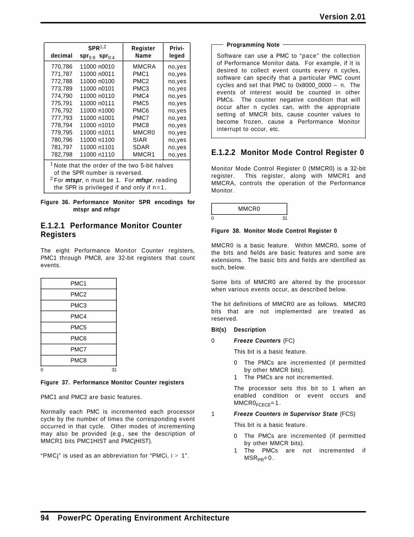
Version 2.01
SPR1,2 Register Privi-decimal spr5:9 spr0:4 Name leged
770,786 11000 n0010 MMCRA no,yes771,787 11000 n0011 PMC1 no,yes772,788 11000 n0100 PMC2 no,yes773,789 11000 n0101 PMC3 no,yes774,790 11000 n0110 PMC4 no,yes775,791 11000 n0111 PMC5 no,yes776,792 11000 n1000 PMC6 no,yes777,793 11000 n1001 PMC7 no,yes778,794 11000 n1010 PMC8 no,yes779,795 11000 n1011 MMCR0 no,yes780,796 11000 n1100 SIAR no,yes781,797 11000 n1101 SDAR no,yes782,798 11000 n1110 MMCR1 no,yes
1 Note that the order of the two 5-bit halvesof the SPR number is reversed.
2 For mtspr, n must be 1. For mfspr, readingthe SPR is privileged if and only if n=1 .
Figure 36. Performance Monitor SPR encodings formtspr and mfspr
E.1.2.1 Performance Monitor CounterRegisters
The eight Performance Monitor Counter registers,PMC1 through PMC8, are 32-bit registers that countevents.
PMC1
PMC2
PMC3
PMC4
PMC5
PMC6
PMC7
PMC8
0 31
Figure 37. Performance Monitor Counter registers
PMC1 and PMC2 are basic features.
Normally each PMC is incremented each processorcycle by the number of times the corresponding eventoccurred in that cycle. Other modes of incrementingmay also be provided (e.g., see the description ofMMCR1 bits PMC1HIST and PMCjHIST).
“PMCj” is used as an abbreviation for “PMCi, i > 1”.
Programming Note
Software can use a PMC to “pace” the collectionof Performance Monitor data. For example, if it isdesired to collect event counts every n cycles,software can specify that a particular PMC countcycles and set that PMC to 0x8000_0000 − n. Theevents of interest would be counted in otherPMCs. The counter negative condition that willoccur after n cycles can, with the appropriatesetting of MMCR bits, cause counter values tobecome frozen, cause a Performance Monitorinterrupt to occur, etc.
E.1.2.2 Monitor Mode Control Register 0
Monitor Mode Control Register 0 (MMCR0) is a 32-bitregister. This register, along with MMCR1 andMMCRA, controls the operation of the PerformanceMonitor.
MMCR0
0 31
Figure 38. Monitor Mode Control Register 0
MMCR0 is a basic feature. Within MMCR0, some ofthe bits and fields are basic features and some areextensions. The basic bits and fields are identified assuch, below.
Some bits of MMCR0 are altered by the processorwhen various events occur, as described below.
The bit definitions of MMCR0 are as follows. MMCR0bits that are not implemented are treated asreserved.
Bit(s) Description
0 Freeze Counters (FC)
This bit is a basic feature.
0 The PMCs are incremented (if permittedby other MMCR bits).
1 The PMCs are not incremented.
The processor sets this bit to 1 when anenabled condition or event occurs andMMCR0FCECE= 1 .
1 Freeze Counters in Supervisor State (FCS)
This bit is a basic feature.
0 The PMCs are incremented (if permittedby other MMCR bits).
1 The PMCs are not incremented ifMSRPR= 0 .
94 PowerPC Operating Environment Architecture

Version 2.01
2 Freeze Counters in Problem State (FCP)
This bit is a basic feature.
0 The PMCs are incremented (if permittedby other MMCR bits).
1 The PMCs are not incremented ifMSRPR= 1 .
3 Freeze Counters while Mark = 1 (FCM1)
This bit is a basic feature.
0 The PMCs are incremented (if permittedby other MMCR bits).
1 The PMCs are not incremented ifMSRPMM= 1 .
4 Freeze Counters while Mark = 0 (FCM0)
This bit is a basic feature.
0 The PMCs are incremented (if permittedby other MMCR bits).
1 The PMCs are not incremented ifMSRPMM= 0 .
5 Performance Monitor Exception Enable(PMXE)
This bit is a basic feature.
0 Performance Monitor exceptions are disa-bled.
1 Performance Monitor exceptions areenabled until a Performance Monitorexception occurs, at which time:■ MMCR0PMXE is set to 0
Programming Note
Software can set this bit to 0 to preventPerformance Monitor interrupts.
Software can set this bit to 1 and then pollthe bit to determine whether an enabledcondition or event has occurred. This isespecially useful on an implementationthat does not provide the PerformanceMonitor interrupt.
6 Freeze Counters on Enabled Condition orEvent (FCECE)
0 The PMCs are incremented (if permittedby other MMCR bits).
1 The PMCs are incremented (if permittedby other MMCR bits) until an enabled con-dition or event occurs whenMMCR0TRIGGER= 0 , at which time:■ MMCR0FC is set to 1
If the enabled condition or event occurs whenMMCR0TRIGGER= 1 , the FCECE bit is treatedas if it were 0.
7:8 Time Base Selector (TBSEL)
This field selects the Time Base bit that cancause a Time Base transition event (the eventoccurs when the selected bit changes from 0to 1).
00 Time Base bit 63 is selected.01 Time Base bit 55 is selected.10 Time Base bit 51 is selected.11 Time Base bit 47 is selected.
Programming Note
Time Base transition events can be usedto collect information about processoractivity, as revealed by event counts inPMCs and by addresses in SIAR andSDAR, at periodic intervals.
In multiprocessor systems in which theTime Base registers are synchronizedamong the processors, Time Base transi-tion events can be used to correlate thePerformance Monitor data obtained by theseveral processors. For this use, softwaremust specify the same TBSEL value for allthe processors in the system.
Because the frequency of the Time Baseis implementation-dependent, softwareshould invoke a system service programto obtain the frequency before choosing avalue for TBSEL.
9 Time Base Event Enable (TBEE)
0 Time Base transition events are disabled.1 Time Base transition events are enabled.
10:15 Threshold (THRESHOLD)
This field contains a “threshold value”, whichis a value such that only events that exceedthe value are counted. The events to which athreshold value can apply are implementa-tion-dependent, as are the dimension of thethreshold (e.g., duration in cycles) and thegranularity with which the threshold value isinterpreted. See the Book IV, PowerPCImplementation Features document for theimplementation.
Programming Note
By varying the threshold value, softwarecan obtain a profile of the characteristicsof the events subject to the threshold.For example, if PMC1 counts the numberof cache misses for which the durationexceeds the threshold value, then soft-ware can obtain the distribution of cachemiss durations for a given program bymonitoring the program repeatedly usinga different threshold value each time.
Appendix E. Example Performance Monitors (Optional) 95

Version 2.01
16 PMC1 Condition Enable (PMC1CE)
This bit controls whether counter negativeconditions due to a negative value in PMC1are enabled.
0 Counter negative conditions for PMC1 aredisabled.
1 Counter negative conditions for PMC1 areenabled.
17 PMCj Condition Enable (PMCjCE)
This bit controls whether counter negativeconditions due to a negative value in anyPMCj (i.e., in any PMC except PMC1) areenabled.
0 Counter negative conditions for all PMCjsare disabled.
1 Counter negative conditions for all PMCjsare enabled.
18 Trigger (TRIGGER)
0 The PMCs are incremented (if permittedby other MMCR bits).
1 PMC1 is incremented (if permitted byother MMCR bits). The PMCjs are notincremented until PMC1 is negative or anenabled condition or event occurs, atwhich time:■ the PMCjs resume incrementing (if
permitted by other MMCR bits)■ MMCR0TRIGGER is set to 0
See the description of the FCECE bit, above,regarding the interaction between TRIGGERand FCECE.
Programming Note
Uses of TRIGGER include the following.
■ Resume counting in the PMCjs whenPMC1 becomes negative, withoutcausing a Performance Monitor inter-rupt. Then freeze all PMCs (andoptionally cause a PerformanceMonitor interrupt) when a PMCjbecomes negative. The PMCjs thenreflect the events that occurredbetween the time PMC1 became neg-ative and the time a PMCj becomesnegative. This use requires the fol-lowing MMCR0 bit settings.
— TRIGGER=1— PMC1CE=0— PMCjCE=1— TBEE=0— FCECE=1— PMXE=1 (if a Performance
Monitor interrupt is desired)
■ Resume counting in the PMCjs whenPMC1 becomes negative, and cause aPerformance Monitor interrupt withoutfreezing any PMCs. The PMCjs thenreflect the events that occurredbetween the time PMC1 became neg-ative and the time the interrupthandler reads them. This userequires the following MMCR0 bit set-tings.
— TRIGGER=1— PMC1CE=1— TBEE=0— FCECE=0— PMXE=1
19:25 PMC1 Selector (PMC1SEL)
This field is a basic feature.
This field contains a code (one of at most 128values) that identifies the event to be countedin PMC1; see the Book IV, PowerPC Imple-mentation Features document for the imple-mentation.
26:31 PMC2 Selector (PMC2SEL)
This field is a basic feature.
This field contains a code (one of at most 64values) that identifies the event to be countedin PMC2; see Book IV.
96 PowerPC Operating Environment Architecture
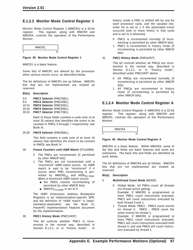
Version 2.01
E.1.2.3 Monitor Mode Control Register 1
Monitor Mode Control Register 1 (MMCR1) is a 32-bitregister. This register, along with MMCR0 andMMCRA, controls the operation of the PerformanceMonitor.
MMCR1
0 31
Figure 39. Monitor Mode Control Register 1
MMCR1 is a basic feature.
Some bits of MMCR1 are altered by the processorwhen various events occur, as described below.
The bit definitions of MMCR1 are as follows. MMCR1bits that are not implemented are treated asreserved.
Bit(s) Description
0:4 PMC3 Selector (PMC3SEL)5:9 PMC4 Selector (PMC4SEL)10:14 PMC5 Selector (PMC5SEL)15:19 PMC6 Selector (PMC6SEL)20:24 PMC7 Selector (PMC7SEL)
Each of these fields contains a code (one of atmost 32 values) that identifies the event to becounted in PMCs 3 through 7 respectively; seeBook IV.
25:28 PMC8 Selector (PMC8SEL)
This field contains a code (one of at most 16values) that identifies the event to be countedin PMC8; see Book IV.
29 Freeze Counters until IABR Match (FCUIABR)
0 The PMCs are incremented (if permittedby other MMCR bits).
1 The PMCs are not incremented until a“monitored” IABR match occurs. An IABRmatch is said to be “monitored” if itoccurs when PMC incrementing is per-mitted by MMCR00:4 and MSRPR PMM.When a monitored IABR match occurs:■ the PMCs resume incrementing (if
permitted by other MMCR bits)■ MMCR1FCUIABR is set to 0
The IABR (Instruction Address BreakpointRegister) is an implementation-specific SPR,and the definition of “IABR match” is imple-mentation-dependent; see the Book IV,PowerPC Implementation Features documentfor the implementation.
30 PMC1 History Mode (PMC1HIST)
This bit controls whether PMC1 is incre-mented in the normal way, described inSection E.1.2.1, or in “history mode”. In
history mode a PMC is shifted left by one biteach processor cycle, and the vacated low-order bit is set to 1 if the associated eventoccurred (one or more times) in that cycleand is set to 0 otherwise.
0 PMC1 is incremented normally (if incre-menting is permitted by other MMCR bits).
1 PMC1 is incremented in history mode (ifincrementing is permitted by other MMCRbits).
31 PMCj History Mode (PMCjHIST)
This bit controls whether all PMCjs are incre-mented in the normal way, described inSection E.1.2.1, or in “history mode”,described under PMC1HIST above.
0 All PMCjs are incremented normally (ifincrementing is permitted by other MMCRbits).
1 All PMCjs are incremented in historymode (if incrementing is permitted byother MMCR bits).
E.1.2.4 Monitor Mode Control Register A
Monitor Mode Control Register A (MMCRA) is a 32-bitregister. This register, along with MMCR0 andMMCR1, controls the operation of the PerformanceMonitor.
MMCRA
0 31
Figure 40. Monitor Mode Control Register A
MMCRA is a basic feature. Within MMCRA, some ofthe bits and fields are basic features and some areextensions. The basic bits and fields are identified assuch, below.
The bit definitions of MMCRA are as follows. MMCRAbits that are not implemented are treated asreserved.
Bit(s) Description
0 Multithread Count Mode (MODE)
0 Global Mode: All PMCs count all threads(no thread active gating).Example: If MMCR0 is programmed tohave PMC1 count instructions executed,PMC1 will count instructions executed byboth thread 0 and 1.
1 Thread Mode: PMC1 - PMC4 count eventstor thread 0. PMC5 - PMC8 count thesame events for thread 1.Example: If MMCR0 is programmed tohave PMC1 count instructions executed,PMC1 will count instructions executed boththread 0, and and PMC5 will count instruc-tion executed by thread 1.
Appendix E. Example Performance Monitors (Optional) 97

Version 2.01
When MODE = 1, the PMC SPR addressingchanges.
■ For thread 0, PMC1 - PMC4 (PerformanceMonitor Counter registers 1 - 4) areaddressed using PMC1 - PMC4 SPRaddresses from Figure 36 on page 94.The results of mfspr or mtspr instructionsthat use a PMC5 - PMC8 SPR address areimplementation-dependent.
■ For thread 1, PMC5 - PMC8 are addressedusing PMC1 - PMC4 SPR addresses fromFigure 36 on page 94. The results ofmfspr or mtspr instructions that use aPMC5 - PMC8 SPR address are implemen-tation-dependent.
1 Freeze Counters 1-4 (FC1-4)
0 PMC1 - PMC4 are incremented (if per-mitted by other MMCR bits).
1 PMC1 - PMC4 are not incremented.
2 Freeze Counters 5-8 (FC5-8)
0 PMC5 - PMC8 are incremented (if per-mitted by other MMCR bits).
1 PMC5 - PMC8 are not incremented.
3:7 Reserved
8:14 Reserved for implementation-specific use
15:23 Reserved
24:27 Reserved for implementation-specific use
28:29 Reserved
30 Freeze Counters in Wait State (FCWAIT)
This bit is a basic feature.
0 The PMCs are incremented (if permittedby other MMCR bits).
1 The PMCs are not incremented ifCTRL31= 0 . Software is expected to setCTRL31= 0 when it is in a “wait state”, i.e,when there is no process ready to run.
Only Branch Unit type of events do not incre-ment if CTRL31= 0 . Other units continue tocount.
31 Reserved
E.1.2.5 Sampled Instruction AddressRegister
The Sampled Instruction Address Register (SIAR) is a64-bit register. It contains the address of the“sampled instruction” when a Performance Monitorexception occurs.
SIAR
0 63
Figure 41. Sampled Instruction Address Register
When a Performance Monitor exception occurs, SIARis set to the effective address of an instruction thatwas executing, possibly out-of-order, at or around thetime that the Performance Monitor exceptionoccurred. This instruction is called the “sampledinstruction”.
The contents of SIAR may be altered by the processorif and only if MMCR0PMXE= 1 . Thus after the Perform-ance Monitor exception occurs, the contents of SIARare not altered by the processor until software setsMMCR0PMXE to 1. After software sets MMCR0PMXE to1, the contents of SIAR are undefined until the nextPerformance Monitor exception occurs.
See Section E.1.4 regarding the effects of the Tracefacility on SIAR.
E.1.2.6 Sampled Data Address Register
The Sampled Data Address Register (SDAR) is a64-bit register. It contains the address of the“sampled data” when a Performance Monitor excep-tion occurs.
SDAR
0 63
Figure 42. Sampled Data Address Register
When a Performance Monitor exception occurs, SDARis set to the effective address of the storage operandof an instruction that was executing, possibly out-of-order, at or around the time that the PerformanceMonitor exception occurred. This storage operand iscalled the “sampled data”. The sampled data maybe, but need not be, the storage operand (if any) ofthe “sampled instruction” (see Section E.1.2.5). If thePerformance Monitor exception causes a PerformanceMonitor interrupt, SRR1 indicates whether thesampled data is in fact the storage operand of thesampled instruction (see Section E.1.3).
The contents of SDAR may be altered by theprocessor if and only if MMCR0PMXE= 1 . Thus afterthe Performance Monitor exception occurs, the con-tents of SDAR are not altered by the processor untilsoftware sets MMCR0PMXE to 1. After software setsMMCR0PMXE to 1, the contents of SDAR are undefineduntil the next Performance Monitor exception occurs.
See Section E.1.4 regarding the effects of the Tracefacility on SDAR.
98 PowerPC Operating Environment Architecture

Version 2.01
E.1.3 Performance Monitor Interrupt
The Performance Monitor interrupt is a system-caused interrupt (see Section 5.3, “Interrupt Classes”on page 52). It is masked by MSREE in the samemanner that External and Decrementer interrupts are.
A Performance Monitor interrupt occurs when nohigher priority exception exists, a PerformanceMonitor exception exists, and MSREE= 1 . The occur-rence of the interrupt cancels the exception (i.e.,causes the exception to cease to exist).
If multiple Performance Monitor exceptions occurbefore the first causes a Performance Monitor inter-rupt, the interrupt reflects the most recent Perform-ance Monitor exception and the precedingPerformance Monitor exceptions are lost.
The following registers are set:
SRR0 Set to the effective address of the instruc-tion that the processor would haveattempted to execute next if no interruptconditions were present.
SRR133 Set to 1 if the contents of SIAR and SDAR
are associated with the same instruction(i.e., if SDAR contains the effective addressof the storage operand of the “sampledinstruction”); otherwise set to 0 (includingthe case in which the “sampledinstruction” has no storage operand).
34:36 and 42:47 See the Book IV, PowerPC Imple-mentation Features document for theimplementation.
Others Loaded from the MSR.
MSR See Figure 28 on page 54.
SIAR Set to the effective address of the“sampled instruction” (see Section E.1.2.5).
SDAR Set to the effective address of the“sampled data” (see Section E.1.2.6).
Execution resumes at effective address0x0000_0000_0000_0F00.
In general, statements about External andDecrementer interrupts elsewhere in this Book applyalso to the Performance Monitor interrupt; forexample, if a Performance Monitor exception ispending when an mtmsr[ d] instruction is executedthat changes MSREE from 0 to 1, the PerformanceMonitor interrupt will occur before the next instructionis executed (if no higher priority exception exists).
The priority of the Performance Monitor interrupt isbetween that of the External interrupt and that of theDecrementer interrupt (see Section 5.7.2, “OrderedExceptions” on page 64 and Section 5.8, “InterruptPriorities” on page 65).
E.1.4 Interaction with the TraceFacility
If the Trace facility includes setting SIAR and SDAR(see Appendix F, “Example Trace Extensions(Optional)” on page 109), and tracing is active(MSRSE= 1 or MSRBE=1) , the contents of SIAR andSDAR as used by the Performance Monitor facility areundefined and may change even whenMMCR0PMXE= 0 , and the contents of SRR133 when aPerformance Monitor interrupt occurs are also unde-fined.
Programming Note
A potential combined use of the Trace and Per-formance Monitor facilities is to trace the controlflow of a program and simultaneously countevents for that program.
E.1.5 Synchronization Requirementsfor Performance Monitor SPRs
Any requirements for synchronizing the effect ofloading Performance Monitor SPRs is implementa-tion-dependent.
Appendix E. Example Performance Monitors (Optional) 99

Version 2.01
E.2 Performance Monitor for POWER4+
The minimal subset of the features listed on page 91that makes the resulting Performance Monitor usefulto software consists of MSRPMM, PMC1, PMC2, PMC3,PMC4, MMCR0, MMCR1, and MMCRA and certain bitsand fields of these three Monitor Mode Control Regis-ters, and the Performance Monitor Interrupt. Thesefeatures are identified as the “basic” features below.The remaining features (the remaining SPRs, and theremaining bits and fields in the three Monitor ModeControl Registers) are considered “extensions”.
The events that can be counted in the PMCs areimplementation-dependent. The Book IV, PowerPCImplementation Features document for the implemen-tation describes the events that are available for eachPMC, and also the code that identifies each event.The events and codes may vary between PMCs, aswell as between implementations. The event to becounted in a given PMC is selected by specifying theappropriate code in the MMCR “Selector” field for thePMC. As described in Book IV, some events mayinclude operations that are performed out-of-order.
Many aspects of the operation of the PerformanceMonitor are summarized by the following hierarchy,which is described starting at the lowest level.
■ A “counter negative condition” exists when thevalue in a PMC is negative (i.e., when bit 0 of thePMC is 1). A “Time Base transition event” occurswhen a selected bit of the Time Base changesfrom 0 to 1 (the bit is selected by an MMCR field).The term “condition or event” is used as anabbreviation for “counter negative condition orTime Base transition event”. A condition orevent can be caused implicitly by the processor(e.g., incrementing a PMC) or explicitly by soft-ware (mtspr).
■ A condition or event is enabled if the corre-sponding “Enable” bit in an MMCR is 1. Theoccurrence of an enabled condition or event canhave side effects within the Performance Monitor,such as causing the PMCs to cease counting.
■ An enabled condition or event causes a Perform-ance Monitor alert if Performance Monitor eventsare enabled by the corresponding “Enable” bit inan MMCR. A single Performance Monitor alertmay reflect multiple enabled conditions andevents.
■ A Performance Monitor alert causes a Perform-ance Monitor exception.
The exception effects of the Performance Monitorare said to be consistent with the contents ofMMCR0PMAO if one of the following statements istrue. (MMCR0PMAO reflects the occurrence ofPerformance Monitor events; see the definition ofthat bit in Section E.2.2.2.)
— MMCR0PMAO= 0 and a Performance Monitorexception does not exist.
— MMCR0PMAO= 1 and a Performance Monitorexception exists.
A context synchronizing instruction or event thatoccurs when MMCR0PMAO= 0 ensures that theexception effects of the Performance Monitor areconsistent with the contents of MMCR0PMAO.
Even without software synchronization, when thecontents of MMCR0PMAO change, the exceptioneffects of the Performance Monitor become con-sistent with the new contents of MMCR0PMAO suf-ficiently soon that the Performance Monitorfacility is useful to software for its intended pur-poses.
■ A Performance Monitor exception causes a Per-formance Monitor interrupt when MSREE= 1 .
Programming Note
The Performance Monitor can be effectively disa-bled (i.e., put into a state in which PerformanceMonitor SPRs are not altered and PerformanceMonitor interrupts do not occur) by settingMMCR0 to 0x0000_0000_8000_0000.
E.2.1 PMM Bit of the Machine StateRegister
The Performance Monitor uses MSR bit PMM, which isdefined as follows.
Bit Description
61 Performance Monitor Mark (PMM)
This bit is a basic feature.
This bit contains the Performance Monitor“mark ” (0 or 1).
100 PowerPC Operating Environment Architecture

Version 2.01
Programming Note
Software can use this bit as a process-specificmarker which, in conjunction withMMCR0FCM0 FCM1 (see Section E.2.2.2), permitsevents to be counted on a process-specific basis.(The bit is saved by interrupts and restored byrfid.)
Common uses of the PMM bit include the fol-lowing.
■ Count events for a few selected processes.This use requires the following bit settings.
— MSRPMM= 1 for the selected processes,MSRPMM= 0 for all other processes
— MMCR0FCM0= 1— MMCR0FCM1= 0
■ Count events for all but a few selected proc-esses. This use requires the following bit set-tings.
— MSRPMM= 1 for the selected processes,MSRPMM= 0 for all other processes
— MMCR0FCM0= 0
— MMCR0FCM1= 1
Notice that for both of these uses a mark value of1 identifies the “ few ” processes and a mark valueof 0 identifies the remaining “many ” processes.Because the PMM bit is set to 0 when an interruptoccurs (see Figure 28 on page 54), interrupt han-dlers are treated as one of the “many” . If it isdesired to treat interrupt handlers as one of the“ few” , the mark value convention just describedwould be reversed.
E.2.2 Special Purpose Registers
The Performance Monitor SPRs count events, controlthe operation of the Performance Monitor, andprovide associated information.
The Performance Monitor SPRs can be read andwritten using the mfspr and mtspr instructions (seeSection 3.4.1, “Move To/From System RegisterInstructions” on page 16). The Performance MonitorSPR numbers are shown in Figure 43. Writing any ofthe Performance Monitor SPRs is privileged. Readingany of the Performance Monitor SPRs is not privileged(however, the privileged SPR numbers used to writethe SPRs can also be used to read them; see thefigure).
The elapsed time between the execution of an instruc-tion and the time at which events due to that instruc-tion have been reflected in Performance Monitor SPRsis not defined. No means are provided by which soft-ware can ensure that all events due to precedinginstructions have been reflected in PerformanceMonitor SPRs. Similarly, if the events being moni-tored may be caused by operations that are per-formed out-of-order, no means are provided by whichsoftware can prevent such events due to subsequentinstructions from being reflected in PerformanceMonitor SPRs. Thus the contents obtained by readinga Performance Monitor SPR may not be precise: itmay fail to reflect some events due to instructionsthat precede the mfspr and may reflect some eventsdue to instructions that follow the mfspr. This lack ofprecision applies regardless of whether the state ofthe processor is such that the SPR is subject tochange by the processor at the time the mfspr is exe-cuted. Similarly, if an mtspr instruction is executedthat changes the contents of the Time Base, thechange is not guaranteed to have taken effect withrespect to causing Time Base transition events untilafter a subsequent context synchronizing instructionhas been executed.
If an mtspr instruction is executed that changes thevalue of a Performance Monitor SPR other than SIARor SDAR, the change is not guaranteed to have takeneffect until after a subsequent context synchronizinginstruction has been executed (see Chapter 7, “Syn-chronization Requirements for Context Alterations” onpage 71).
Programming Note
Depending on the events being monitored, thecontents of Performance Monitor SPRs may beaffected by aspects of the runtime environment(e.g., cache contents) that are not directly attribut-able to the programs being monitored.
Appendix E. Example Performance Monitors (Optional) 101
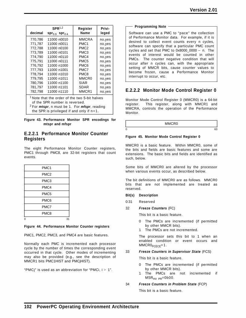
Version 2.01
SPR1,2 Register Privi-decimal spr5:9 spr0:4 Name leged
770,786 11000 n0010 MMCRA no,yes771,787 11000 n0011 PMC1 no,yes772,788 11000 n0100 PMC2 no,yes773,789 11000 n0101 PMC3 no,yes774,790 11000 n0110 PMC4 no,yes775,791 11000 n0111 PMC5 no,yes776,792 11000 n1000 PMC6 no,yes777,793 11000 n1001 PMC7 no,yes778,794 11000 n1010 PMC8 no,yes779,795 11000 n1011 MMCR0 no,yes780,796 11000 n1100 SIAR no,yes781,797 11000 n1101 SDAR no,yes782,798 11000 n1110 MMCR1 no,yes
1 Note that the order of the two 5-bit halvesof the SPR number is reversed.
2 For mtspr, n must be 1. For mfspr, readingthe SPR is privileged if and only if n=1 .
Figure 43. Performance Monitor SPR encodings formtspr and mfspr
E.2.2.1 Performance Monitor CounterRegisters
The eight Performance Monitor Counter registers,PMC1 through PMC8, are 32-bit registers that countevents.
PMC1
PMC2
PMC3
PMC4
PMC5
PMC6
PMC7
PMC8
0 31
Figure 44. Performance Monitor Counter registers
PMC1, PMC2, PMC3, and PMC4 are basic features.
Normally each PMC is incremented each processorcycle by the number of times the corresponding eventoccurred in that cycle. Other modes of incrementingmay also be provided (e.g., see the description ofMMCR1 bits PMC1HIST and PMCjHIST).
“PMCj” is used as an abbreviation for “PMCi, i > 1”.
Programming Note
Software can use a PMC to “pace” the collectionof Performance Monitor data. For example, if it isdesired to collect event counts every n cycles,software can specify that a particular PMC countcycles and set that PMC to 0x8000_0000 − n. Theevents of interest would be counted in otherPMCs. The counter negative condition that willoccur after n cycles can, with the appropriatesetting of MMCR bits, cause counter values tobecome frozen, cause a Performance Monitorinterrupt to occur, etc.
E.2.2.2 Monitor Mode Control Register 0
Monitor Mode Control Register 0 (MMCR0) is a 64-bitregister. This register, along with MMCR1 andMMCRA, controls the operation of the PerformanceMonitor.
MMCR0
0 63
Figure 45. Monitor Mode Control Register 0
MMCR0 is a basic feature. Within MMCR0, some ofthe bits and fields are basic features and some areextensions. The basic bits and fields are identified assuch, below.
Some bits of MMCR0 are altered by the processorwhen various events occur, as described below.
The bit definitions of MMCR0 are as follows. MMCR0bits that are not implemented are treated asreserved.
Bit(s) Description
0:31 Reserved
32 Freeze Counters (FC)
This bit is a basic feature.
0 The PMCs are incremented (if permittedby other MMCR bits).
1 The PMCs are not incremented.
The processor sets this bit to 1 when anenabled condition or event occurs andMMCR0FCECE= 1 .
33 Freeze Counters in Supervisor State (FCS)
This bit is a basic feature.
0 The PMCs are incremented (if permittedby other MMCR bits).
1 The PMCs are not incremented ifMSRHV PR=0b00.
34 Freeze Counters in Problem State (FCP)
This bit is a basic feature.
102 PowerPC Operating Environment Architecture
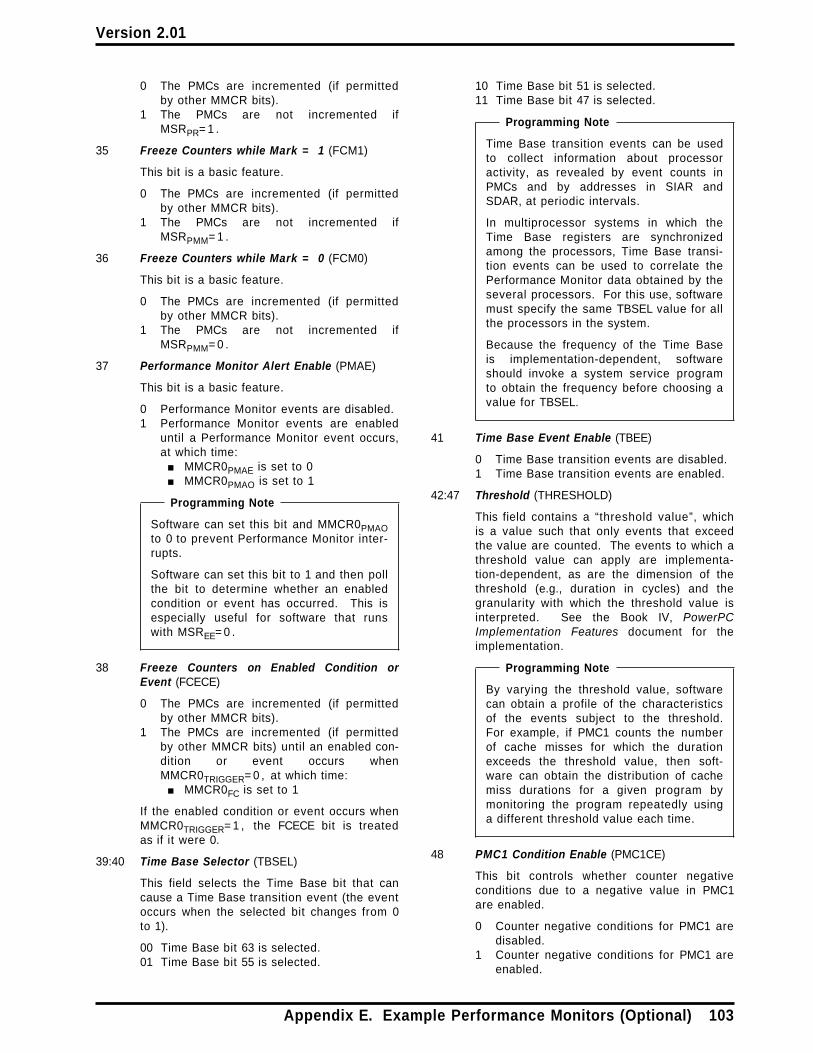
Version 2.01
0 The PMCs are incremented (if permittedby other MMCR bits).
1 The PMCs are not incremented ifMSRPR= 1 .
35 Freeze Counters while Mark = 1 (FCM1)
This bit is a basic feature.
0 The PMCs are incremented (if permittedby other MMCR bits).
1 The PMCs are not incremented ifMSRPMM= 1 .
36 Freeze Counters while Mark = 0 (FCM0)
This bit is a basic feature.
0 The PMCs are incremented (if permittedby other MMCR bits).
1 The PMCs are not incremented ifMSRPMM= 0 .
37 Performance Monitor Alert Enable (PMAE)
This bit is a basic feature.
0 Performance Monitor events are disabled.1 Performance Monitor events are enabled
until a Performance Monitor event occurs,at which time:■ MMCR0PMAE is set to 0■ MMCR0PMAO is set to 1
Programming Note
Software can set this bit and MMCR0PMAOto 0 to prevent Performance Monitor inter-rupts.
Software can set this bit to 1 and then pollthe bit to determine whether an enabledcondition or event has occurred. This isespecially useful for software that runswith MSREE= 0 .
38 Freeze Counters on Enabled Condition orEvent (FCECE)
0 The PMCs are incremented (if permittedby other MMCR bits).
1 The PMCs are incremented (if permittedby other MMCR bits) until an enabled con-dition or event occurs whenMMCR0TRIGGER= 0 , at which time:■ MMCR0FC is set to 1
If the enabled condition or event occurs whenMMCR0TRIGGER= 1 , the FCECE bit is treatedas if it were 0.
39:40 Time Base Selector (TBSEL)
This field selects the Time Base bit that cancause a Time Base transition event (the eventoccurs when the selected bit changes from 0to 1).
00 Time Base bit 63 is selected.01 Time Base bit 55 is selected.
10 Time Base bit 51 is selected.11 Time Base bit 47 is selected.
Programming Note
Time Base transition events can be usedto collect information about processoractivity, as revealed by event counts inPMCs and by addresses in SIAR andSDAR, at periodic intervals.
In multiprocessor systems in which theTime Base registers are synchronizedamong the processors, Time Base transi-tion events can be used to correlate thePerformance Monitor data obtained by theseveral processors. For this use, softwaremust specify the same TBSEL value for allthe processors in the system.
Because the frequency of the Time Baseis implementation-dependent, softwareshould invoke a system service programto obtain the frequency before choosing avalue for TBSEL.
41 Time Base Event Enable (TBEE)
0 Time Base transition events are disabled.1 Time Base transition events are enabled.
42:47 Threshold (THRESHOLD)
This field contains a “threshold value”, whichis a value such that only events that exceedthe value are counted. The events to which athreshold value can apply are implementa-tion-dependent, as are the dimension of thethreshold (e.g., duration in cycles) and thegranularity with which the threshold value isinterpreted. See the Book IV, PowerPCImplementation Features document for theimplementation.
Programming Note
By varying the threshold value, softwarecan obtain a profile of the characteristicsof the events subject to the threshold.For example, if PMC1 counts the numberof cache misses for which the durationexceeds the threshold value, then soft-ware can obtain the distribution of cachemiss durations for a given program bymonitoring the program repeatedly usinga different threshold value each time.
48 PMC1 Condition Enable (PMC1CE)
This bit controls whether counter negativeconditions due to a negative value in PMC1are enabled.
0 Counter negative conditions for PMC1 aredisabled.
1 Counter negative conditions for PMC1 areenabled.
Appendix E. Example Performance Monitors (Optional) 103

Version 2.01
49 PMCj Condition Enable (PMCjCE)
This bit controls whether counter negativeconditions due to a negative value in anyPMCj (i.e., in any PMC except PMC1) areenabled.
0 Counter negative conditions for all PMCjsare disabled.
1 Counter negative conditions for all PMCjsare enabled.
50 Trigger (TRIGGER)
0 The PMCs are incremented (if permittedby other MMCR bits).
1 PMC1 is incremented (if permitted byother MMCR bits). The PMCjs are notincremented until PMC1 is negative or anenabled condition or event occurs, atwhich time:■ the PMCjs resume incrementing (if
permitted by other MMCR bits)■ MMCR0TRIGGER is set to 0
See the description of the FCECE bit, above,regarding the interaction between TRIGGERand FCECE.
Programming Note
Uses of TRIGGER include the following.
■ Resume counting in the PMCjs whenPMC1 becomes negative, withoutcausing a Performance Monitor inter-rupt. Then freeze all PMCs (andoptionally cause a PerformanceMonitor interrupt) when a PMCjbecomes negative. The PMCjs thenreflect the events that occurredbetween the time PMC1 became neg-ative and the time a PMCj becomesnegative. This use requires the fol-lowing MMCR0 bit settings.
— TRIGGER=1— PMC1CE=0— PMCjCE=1— TBEE=0— FCECE=1— PMAE=1 (if a Performance
Monitor interrupt is desired)
■ Resume counting in the PMCjs whenPMC1 becomes negative, and cause aPerformance Monitor interrupt withoutfreezing any PMCs. The PMCjs thenreflect the events that occurredbetween the time PMC1 became neg-ative and the time the interrupthandler reads them. This userequires the following MMCR0 bit set-tings.
— TRIGGER=1— PMC1CE=1— TBEE=0— FCECE=0— PMAE=1
51:55 PMC1 Selector (PMC1SEL)
This field is a basic feature.
This field contains a code (one of at most 32values) that identifies the event to be countedin PMC1; see the Book IV, PowerPC Imple-mentation Features document for the imple-mentation.
56 Performance Monitor Alert Occurred (PMAO)
This bit is a basic feature.
0 A Performance Monitor event has notoccurred since the last time software setthis bit to 0.
1 A Performance Monitor event hasoccurred since the last time software setthis bit to 0.
This bit is set to 1 by the processor when aPerformance Monitor event occurs. This bitcan be set to 0 only by the mtspr instruction.
Programming Note
Software can set this bit to 1 to simulatethe occurrence of a Performance Monitorevent.
Software should set this bit to 0 after han-dling the Performance Monitor event.
This bit was first implemented in thePOWER4+ processor.
57 Reserved
58:62 PMC2 Selector (PMC2SEL)
This field is a basic feature.
This field contains a code (one of at most 32values) that identifies the event to be countedin PMC2; see Book IV.
63 Freeze Counters in Hypervisor State (FCH)
This bit is a basic feature.
0 The PMCs are incremented (if permittedby other MMCR bits).
1 The PMCs are not incremented ifMSRHV PR=0b10.
104 PowerPC Operating Environment Architecture

Version 2.01
E.2.2.3 Monitor Mode Control Register 1
Monitor Mode Control Register 1 (MMCR1) is a 64-bitregister. This register, along with MMCR0 andMMCRA, controls the operation of the PerformanceMonitor.
MMCR1
0 63
Figure 46. Monitor Mode Control Register 1
MMCR1 is a basic feature. Within MMCR1, some ofthe bits and fields are basic features and some areextensions. The basic bits and fields are identified assuch, below.
Some bits of MMCR1 are altered by the processorwhen various events occur, as described below.
The bit definitions of MMCR1 are as follows. MMCR1bits that are not implemented are treated asreserved.
Bit(s) Description
0:31 Implementation-Dependent Use
These bits have implementation-dependentuses (e.g., extended event selection).
32:36 PMC3 Selector (PMC3SEL)37:41 PMC4 Selector (PMC4SEL)42:46 PMC5 Selector (PMC5SEL)47:51 PMC6 Selector (PMC6SEL)52:56 PMC7 Selector (PMC7SEL)57:61 PMC8 Selector (PMC8SEL)
Each of these fields contains a code (one of atmost 32 values) that identifies the event to becounted in PMCs 3 through 8 respectively; seeBook IV.
PMC3SEL and PMC4SEL are basic features.
Compatibility Note
In versions of the architecture thatprecede Version 2.01 the PMC8SEL fieldwas only four bits long, comprisingMMCR125:28, and MMCR129 was theFCUIABR (Freeze Counters until IABRMatch) bit.
62 PMC1 History Mode (PMC1HIST)
This bit controls whether PMC1 is incre-mented in the normal way, described inSection E.2.2.1, or in “history mode”. Inhistory mode a PMC is shifted left by one biteach processor cycle, and the vacated low-order bit is set to 1 if the associated eventoccurred (one or more times) in that cycleand is set to 0 otherwise.
0 PMC1 is incremented normally (if incre-menting is permitted by other MMCR bits).
1 PMC1 is incremented in history mode (ifincrementing is permitted by other MMCRbits).
63 PMCj History Mode (PMCjHIST)
This bit controls whether all PMCjs are incre-mented in the normal way, described inSection E.2.2.1, or in “history mode”,described under PMC1HIST above.
0 All PMCjs are incremented normally (ifincrementing is permitted by other MMCRbits).
1 All PMCjs are incremented in historymode (if incrementing is permitted byother MMCR bits).
E.2.2.4 Monitor Mode Control Register A
Monitor Mode Control Register A (MMCRA) is a 64-bitregister. This register, along with MMCR0 andMMCR1, controls the operation of the PerformanceMonitor.
MMCRA
0 63
Figure 47. Monitor Mode Control Register A
MMCRA is a basic feature. Within MMCRA, some ofthe bits and fields are basic features and some areextensions. The basic bits and fields are identified assuch, below.
Some bits of MMCRA are altered by the processorwhen various events occur, as described below.
The bit definitions of MMCRA are as follows. MMCRAbits that are not implemented are treated asreserved.
Bit(s) Description
0:31 Reserved
32 Contents of SIAR and SDAR Are Related (CSSR)
Set to 1 by the processor if the contents ofSIAR and SDAR are associated with the sameinstruction; otherwise set to 0.
33 Freeze Counters 1-4 (FC1-4)
0 PMC1 - PMC4 are incremented (if per-mitted by other MMCR bits).
1 PMC1 - PMC4 are not incremented.
34 Freeze Counters 5-8 (FC5-8)
0 PMC5 - PMC8 are incremented (if per-mitted by other MMCR bits).
1 PMC5 - PMC8 are not incremented.
Appendix E. Example Performance Monitors (Optional) 105

Version 2.01
35 Sampled MSRHV (SAMPHV)
Value of MSRHV when the PerformanceMonitor Alert occurred.
36 Sampled MSRPR (SAMPPR)
Value of MSRPR when the PerformanceMonitor Alert occurred.
37:46 Setting is implementation-dependent
See Book IV.
47:48 Reserved
49:59 Reserved for implementation-specific use
60:61 Reserved
62 Freeze Counters in Wait State (FCWAIT)
This bit is a basic feature.
0 The PMCs are incremented (if permittedby other MMCR bits).
1 The PMCs are not incremented ifCTRL31= 0 . Software is expected to setCTRL31= 0 when it is in a “wait state”, i.e,when there is no process ready to run.
Only Branch Unit type of events do not incre-ment if CTRL31= 0 . Other units continue tocount.
63 Reserved for implementation-specific use
E.2.2.5 Sampled Instruction AddressRegister
The Sampled Instruction Address Register (SIAR) is a64-bit register. It contains the address of the“sampled instruction” when a Performance Monitoralert occurs.
SIAR
0 63
Figure 48. Sampled Instruction Address Register
When a Performance Monitor alert occurs, SIAR is setto the effective address of an instruction that wasbeing executed, possibly out-of-order, at or aroundthe time that the Performance Monitor alert occurred.This instruction is called the “sampled instruction”.
The contents of SIAR may be altered by the processorif and only if MMCR0PMAE= 1 . Thus after the Perform-ance Monitor alert occurs, the contents of SIAR arenot altered by the processor until software sets
MMCR0PMAE to 1. After software sets MMCR0PMAE to1, the contents of SIAR are undefined until the nextPerformance Monitor alert occurs.
See Section E.2.4 regarding the effects of the Tracefacility on SIAR.
Programming Note
If the Performance Monitor alert causes a Perform-ance Monitor interrupt, the value of MSRHV PR thatwas in effect when the sampled instruction wasbeing executed is reported in MMCRA.
E.2.2.6 Sampled Data Address Register
The Sampled Data Address Register (SDAR) is a64-bit register. It contains the address of the“sampled data” when a Performance Monitor alertoccurs.
SDAR
0 63
Figure 49. Sampled Data Address Register
When a Performance Monitor alert occurs, SDAR isset to the effective address of the storage operand ofan instruction that was being executed, possibly out-of-order, at or around the time that the PerformanceMonitor alert occurred. This storage operand iscalled the “sampled data”. The sampled data maybe, but need not be, the storage operand (if any) ofthe sampled instruction (see Section E.2.2.5).
The contents of SDAR may be altered by theprocessor if and only if MMCR0PMAE= 1 . Thus afterthe Performance Monitor alert occurs, the contents ofSDAR are not altered by the processor until softwaresets MMCR0PMAE to 1. After software setsMMCR0PMAE to 1, the contents of SDAR are undefineduntil the next Performance Monitor alert occurs.
See Section E.2.4 regarding the effects of the Tracefacility on SDAR.
Programming Note
If the Performance Monitor alert causes a Per-formance Monitor interrupt, MMCRA indicateswhether the sampled data is the storage operandof the sampled instruction.
106 PowerPC Operating Environment Architecture
Version 2.01
E.2.3 Performance Monitor Interrupt
The Performance Monitor interrupt is a system-caused interrupt (see Section 5.3, “Interrupt Classes”on page 52). It is masked by MSREE in the samemanner that External and Decrementer interrupts are.
The Performance Monitor interrupt is a basic feature.
A Performance Monitor interrupt occurs when nohigher priority exception exists, a PerformanceMonitor exception exists, and MSREE= 1 .
If multiple Performance Monitor exceptions occurbefore the first causes a Performance Monitor inter-rupt, the interrupt reflects the most recent Perform-ance Monitor exception and the precedingPerformance Monitor exceptions are lost.
The following registers are set:
SRR0 Set to the effective address of the instruc-tion that the processor would haveattempted to execute next if no interruptconditions were present.
SRR133:36 and 42:47 See the Book IV, PowerPC Imple-
mentation Features document for theimplementation.
Others Loaded from the MSR.
MSR See Figure 28 on page 54.
SIAR Set to the effective address of the“sampled instruction” (see Section E.2.2.5).
SDAR Set to the effective address of the“sampled data” (see Section E.2.2.6).
Execution resumes at effective address0x0000_0000_0000_0F00.
In general, statements about External andDecrementer interrupts elsewhere in this Book applyalso to the Performance Monitor interrupt; forexample, if a Performance Monitor exception existswhen an mtmsrd[ d] instruction is executed thatchanges MSREE from 0 to 1, the Performance Monitorinterrupt will occur before the next instruction is exe-cuted (if no higher priority exception exists).
The priority of the Performance Monitor exception isequal to that of the External, Decrementer, andHypervisor Decrementer exceptions (i.e., theprocessor may generate any one of the four inter-rupts for which an exception exists) (see Section 5.7.2,“Ordered Exceptions” on page 64 and Section 5.8,“Interrupt Priorities” on page 65).
E.2.4 Interaction with the TraceFacility
If the Trace facility includes setting SIAR and SDAR(see Appendix F, “Example Trace Extensions(Optional)” on page 109), and tracing is active(MSRSE= 1 or MSRBE=1) , the contents of SIAR andSDAR as used by the Performance Monitor facility areundefined and may change even whenMMCR0PMAE= 0 .
Programming Note
A potential combined use of the Trace and Per-formance Monitor facilities is to trace the controlflow of a program and simultaneously countevents for that program.
Appendix E. Example Performance Monitors (Optional) 107

Version 2.01
108 PowerPC Operating Environment Architecture
Version 2.01
Appendix F. Example Trace Extensions (Optional)
This appendix provides an example of extensions thatmay be added to the Trace facility described inSection 5.5.14, “Trace Interrupt” on page 63. It isonly an example; implementations may provide all,some, or none of the features described here, or mayprovide features that are similar to those describedhere but differ in detail. See the Book IV, PowerPCImplementation Features document for the implemen-tation.
The extensions consist of the following features(described in detail below).
■ use of MSRSE BE=0b11 to specify new causes ofTrace interrupts
■ specification of how certain SRR1 bits are setwhen a Trace interrupt occurs
■ setting of SIAR and SDAR (see Appendix E) whena Trace interrupt occurs
MSRSE BE = 0b11
If MSRSE BE=0b11, the processor generates a Traceexception under the conditions described in Section5.5.14 for MSRSE BE=0b01, and also after successfullycompleting the execution of any instruction that wouldcause at least one of SRR1 bits 33:36, 42, and 44:46 tobe set to 1 (see below) if the instruction were exe-cuted when MSRSE BE=0b10.
This overrides the implicit statement in Section 5.5.14that the effects of MSRSE BE=0b11 are the same asthose of MSRSE BE=0b10.
SRR1
When a Trace interrupt occurs, the SRR1 bits that arenot loaded from the MSR are set as follows instead ofas described in Section 5.5.14.
33 Set to 1 if the traced instruction is icbi; oth-erwise set to 0.
34 Set to 1 if the traced instruction is dcbt,dcbtst, dcbz, dcbst, or dcbf; otherwise setto 0.
35 Set to 1 if the traced instruction is a Loadinstruction or eciwx; may be set to 1 if thetraced instruction is icbi, dcbt, dcbtst,dcbst, or dcbf; otherwise set to 0.
36 Set to 1 if the traced instruction is a Storeinstruction, dcbz, or ecowx; otherwise setto 0.
42 Set to 1 if the traced instruction is lswx orstswx; otherwise set to 0.
43 See the Book IV, PowerPC ImplementationFeatures document for the implementation.
44 Set to 1 if the traced instruction is aBranch instruction and the branch is taken;otherwise set to 0.
45 Set to 1 if the traced instruction is eciwx orecowx; otherwise set to 0.
46 Set to 1 if the traced instruction is lwarx,ldarx, stwcx., or stdcx.; otherwise set to 0.
47 See the Book IV, PowerPC ImplementationFeatures document for the implementation.
SIAR and SDAR
If the optional Performance Monitor facility is imple-mented and includes SIAR and SDAR (seeAppendix E, “Example Performance Monitors(Optional)” on page 91), the following additional reg-isters are set when a Trace interrupt occurs:
SIAR Set to the effective address of the tracedinstruction.
SDAR Set to the effective address of the storageoperand (if any) of the traced instruction;otherwise undefined.
If the state of the Performance Monitor is such thatthe Performance Monitor may be altering these regis-ters (i.e., if MMCR0PMAE=1) , the contents of SIAR andSDAR as used by the Trace facility are undefined andmay change even when no Trace interrupt occurs.
Appendix F. Example Trace Extensions (Optional) 109
Version 2.01
110 PowerPC Operating Environment Architecture
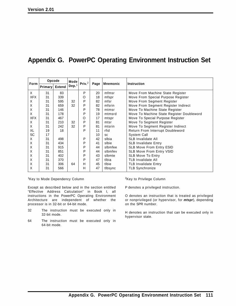
Version 2.01
Appendix G. PowerPC Operating Environment Instruction Set
FormOpcode Mode
Dep.1Priv.2 Page Mnemonic Instruction
Primary Extend
X 31 83 P 20 mfmsr Move From Machine State RegisterXFX 31 339 O 18 mfspr Move From Special Purpose RegisterX 31 595 32 P 82 mfsr Move From Segment RegisterX 31 659 32 P 82 mfsrin Move From Segment Register IndirectX 31 146 P 78 mtmsr Move To Machine State RegisterX 31 178 P 19 mtmsrd Move To Machine State Register DoublewordXFX 31 467 O 17 mtspr Move To Special Purpose RegisterX 31 210 32 P 81 mtsr Move To Segment RegisterX 31 242 32 P 81 mtsrin Move To Segment Register IndirectXL 19 18 P 11 rfid Return From Interrupt DoublewordSC 17 10 sc System CallX 31 498 P 42 slbia SLB Invalidate AllX 31 434 P 41 slbie SLB Invalidate EntryX 31 915 P 44 slbmfee SLB Move From Entry ESIDX 31 851 P 44 slbmfev SLB Move From Entry VSIDX 31 402 P 43 slbmte SLB Move To EntryX 31 370 P 47 tlbia TLB Invalidate AllX 31 306 64 H 45 tlbie TLB Invalidate EntryX 31 566 H 47 tlbsync TLB Synchronize
1Key to Mode Dependency Column
Except as described below and in the section entitled“Effective Address Calculation” in Book I, allinstructions in the PowerPC Operating EnvironmentArchitecture are independent of whether theprocessor is in 32-bit or 64-bit mode.
32 The instruction must be executed only in32-bit mode.
64 The instruction must be executed only in64-bit mode.
2Key to Privilege Column
P denotes a privileged instruction.
O denotes an instruction that is treated as privilegedor nonprivileged (or hypervisor, for mtspr), dependingon the SPR number.
H denotes an instruction that can be executed only inhypervisor state.
Appendix G. PowerPC Operating Environment Instruction Set 111

Version 2.01
112 PowerPC Operating Environment Architecture

Version 2.01
Index
A
ACCR 34address
effective address 21real 23, 25
address compare 22, 55ACCR 34
Address Compare Control Register 17, 18, 34Address Space Register 17, 18, 79address translation 37
EA to VA 25esid to vsid 25overview 28PTE
page table entry 31, 37Reference bit 37RPN
real page number 30VA to RA 30VPN
virtual page number 3032-bit mode 25
address wrap 23addresses
accessed by processor 27implicit accesses 27interrupt vectors 27with defined uses 27
Alignment interrupt 59, 89ASR 79assembler language
extended mnemonics 83mnemonics 83symbols 83
B
BESee Machine State Register
Branch Trace 63Bridge 79
ASR 79Segment Registers 80SR 80
C
Caching Inhibited 22Change bit 37CIA
See Current Instruction Addresscontext
definition 1synchronization 3
Control Register 0 14, 17, 18CTRL
See Control RegisterCurrent Instruction Address 7, 10
D
DABR interrupt 35DAR
See Data Address Registerdata access 23Data Address Breakpoint Register 17, 18, 35data address compare 55
ACCR 34Data Address Register 13, 17, 18, 56, 57, 60Data Segment interrupt 57Data Storage interrupt 55Data Storage Interrupt Status Register 14, 17, 18,
56, 59, 60, 89Alignment interrupt 89
dcbf instruction 55dcbst instruction 55dcbz instruction 34, 40, 55, 59, 89Decrementer 17, 18, 68, 69Decrementer interrupt 19, 61, 78DR
See Machine State RegisterDSISR
See Data Storage Interrupt Status Register
E
E (Enable bit) 75eciwx instruction 75, 55, 59, 60
Index 113
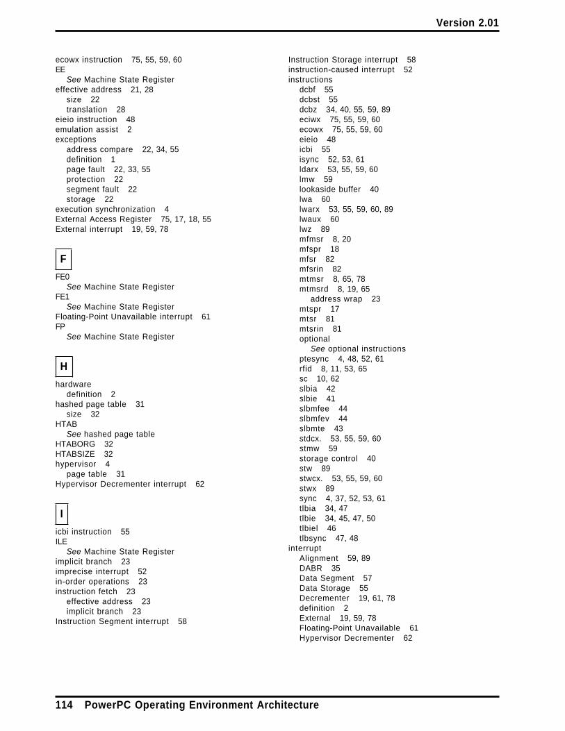
Version 2.01
ecowx instruction 75, 55, 59, 60EE
See Machine State Registereffective address 21, 28
size 22translation 28
eieio instruction 48emulation assist 2exceptions
address compare 22, 34, 55definition 1page fault 22, 33, 55protection 22segment fault 22storage 22
execution synchronization 4External Access Register 75, 17, 18, 55External interrupt 19, 59, 78
F
FE0See Machine State Register
FE1See Machine State Register
Floating-Point Unavailable interrupt 61FP
See Machine State Register
H
hardwaredefinition 2
hashed page table 31size 32
HTABSee hashed page table
HTABORG 32HTABSIZE 32hypervisor 4
page table 31Hypervisor Decrementer interrupt 62
I
icbi instruction 55ILE
See Machine State Registerimplicit branch 23imprecise interrupt 52in-order operations 23instruction fetch 23
effective address 23implicit branch 23
Instruction Segment interrupt 58
Instruction Storage interrupt 58instruction-caused interrupt 52instructions
dcbf 55dcbst 55dcbz 34, 40, 55, 59, 89eciwx 75, 55, 59, 60ecowx 75, 55, 59, 60eieio 48icbi 55isync 52, 53, 61ldarx 53, 55, 59, 60lmw 59lookaside buffer 40lwa 60lwarx 53, 55, 59, 60, 89lwaux 60lwz 89mfmsr 8, 20mfspr 18mfsr 82mfsrin 82mtmsr 8, 65, 78mtmsrd 8, 19, 65
address wrap 23mtspr 17mtsr 81mtsrin 81optional
See optional instructionsptesync 4, 48, 52, 61rfid 8, 11, 53, 65sc 10, 62slbia 42slbie 41slbmfee 44slbmfev 44slbmte 43stdcx. 53, 55, 59, 60stmw 59storage control 40stw 89stwcx. 53, 55, 59, 60stwx 89sync 4, 37, 52, 53, 61tlbia 34, 47tlbie 34, 45, 47, 50tlbiel 46tlbsync 47, 48
interruptAlignment 59, 89DABR 35Data Segment 57Data Storage 55Decrementer 19, 61, 78definition 2External 19, 59, 78Floating-Point Unavailable 61Hypervisor Decrementer 62
114 PowerPC Operating Environment Architecture

Version 2.01
interrupt (continued)imprecise 52Instruction Segment 58Instruction Storage 58instruction-caused 52Machine Check 55new MSR 54overview 51Performance Monitor 63precise 52priorities 65processing 53Program 60recoverable 53synchronization 51System Call 62System Reset 55system-caused 52Trace 63vector 53, 54
IRSee Machine State Register
isync instruction 52, 53, 61
K
K bits 39key, storage 39
L
large page 29ldarx instruction 53, 55, 59, 60LE
See Machine State Registerlmw instruction 59Logical Partition Identity Register 5Logical Partitioning 4lookaside buffer 40lookaside buffers 71LPAR (see Logical Partitioning) 4LPES bit 4LPIDR 5lwa instruction 60lwarx instruction 53, 55, 59, 60, 89lwaux instruction 60lwz instruction 89
M
Machine Check interrupt 55Machine State Register 8, 10, 19, 20, 52, 53, 54, 78
BE Branch Trace Enable 9DR Data Relocate 9EE External Interrupt Enable 8, 19, 78FE0 FP Exception Mode 8
Machine State Register (continued)FE1 FP Exception Mode 9FP FP Available 8ILE Interrupt Little-Endian Mode 8IR Instruction Relocate 9LE Little-Endian Mode 9ME Machine Check Enable 8PMM Performance Monitor Mark 9, 92, 100PR Problem State 8RI Recoverable Interrupt 9, 19, 78SE Single-Step Trace Enable 8SF Sixty Four Bit mode 8, 23
Machine Status Save Restore RegisterSee SRR0, SRR1
Machine Status Save Restore Register 0 7, 17, 18,52, 53
Machine Status Save Restore Register 1 7, 17, 18,53, 61
MESee Machine State Register
Memory Coherence Required 22mfmsr instruction 8, 20mfspr instruction 18mfsr instruction 82mfsrin instruction 82mnemonics
extended 83mode change 23MSR
See Machine State Registermtmsr instruction 8, 65, 78mtmsrd instruction 8, 19, 65mtspr instruction 17mtsr instruction 81mtsrin instruction 81
N
Next Instruction Address 7, 10, 11NIA
See Next Instruction Address
O
opcode 0 89optional facilities 79optional instructions 40, 75
slbia 42slbie 41tlbia 47tlbie 45tlbiel 46tlbsync 47
out-of-order operations 23
Index 115
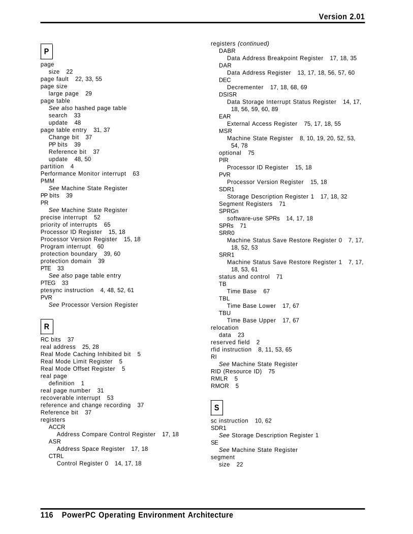
Version 2.01
P
pagesize 22
page fault 22, 33, 55page size
large page 29page table
See also hashed page tablesearch 33update 48
page table entry 31, 37Change bit 37PP bits 39Reference bit 37update 48, 50
partition 4Performance Monitor interrupt 63PMM
See Machine State RegisterPP bits 39PR
See Machine State Registerprecise interrupt 52priority of interrupts 65Processor ID Register 15, 18Processor Version Register 15, 18Program interrupt 60protection boundary 39, 60protection domain 39PTE 33
See also page table entryPTEG 33ptesync instruction 4, 48, 52, 61PVR
See Processor Version Register
R
RC bits 37real address 25, 28Real Mode Caching Inhibited bit 5Real Mode Limit Register 5Real Mode Offset Register 5real page
definition 1real page number 31recoverable interrupt 53reference and change recording 37Reference bit 37registers
ACCRAddress Compare Control Register 17, 18
ASRAddress Space Register 17, 18
CTRLControl Register 0 14, 17, 18
registers (continued)DABR
Data Address Breakpoint Register 17, 18, 35DAR
Data Address Register 13, 17, 18, 56, 57, 60DEC
Decrementer 17, 18, 68, 69DSISR
Data Storage Interrupt Status Register 14, 17,18, 56, 59, 60, 89
EARExternal Access Register 75, 17, 18, 55
MSRMachine State Register 8, 10, 19, 20, 52, 53,
54, 78optional 75PIR
Processor ID Register 15, 18PVR
Processor Version Register 15, 18SDR1
Storage Description Register 1 17, 18, 32Segment Registers 71SPRGn
software-use SPRs 14, 17, 18SPRs 71SRR0
Machine Status Save Restore Register 0 7, 17,18, 52, 53
SRR1Machine Status Save Restore Register 1 7, 17,
18, 53, 61status and control 71TB
Time Base 67TBL
Time Base Lower 17, 67TBU
Time Base Upper 17, 67relocation
data 23reserved field 2rfid instruction 8, 11, 53, 65RI
See Machine State RegisterRID (Resource ID) 75RMLR 5RMOR 5
S
sc instruction 10, 62SDR1
See Storage Description Register 1SE
See Machine State Registersegment
size 22
116 PowerPC Operating Environment Architecture
Version 2.01
segment (continued)type 22
Segment Lookaside BufferSee SLB
Segment Registers 71, 80Segment Table
bridge 79sequential execution model
definition 2SF
See Machine State RegisterSingle-Step Trace 63SLB 29, 40
entry 29slbia instruction 42slbie instruction 41slbmfee instruction 44slbmfev instruction 44slbmte instruction 43software-use SPRs 14, 17, 18speculative operations 23SPRGn
See software use SPRsSPRs 71SR 80status and control registers 71stdcx. instruction 53, 55, 59, 60stmw instruction 59storage
accessed by processor 27consistency 22G 39Guarded 39implicit accesses 27interrupt vectors 27K 39key 39N 33, 39no-execute 33, 39ordering 22PP 39PR 39protection 39
translation disabled 39weak ordering 22with defined uses 27
storage controlinstructions 40
storage control bits 35Storage Description Register 1 17, 18, 32storage key 39storage model 22storage operations
in-order 23out-of-order 23speculative 23
storage protection 39stw instruction 89
stwcx. instruction 53, 55, 59, 60stwx instruction 89symbols 83sync instruction 4, 37, 52, 53, 61synchronization 3, 48, 71
context 3execution 4interrupts 51
System Call interrupt 62System Reset interrupt 55system-caused interrupt 52
T
table update 48Time Base 67Time Base Lower 17, 67Time Base Upper 17, 67TLB 34, 40tlbia instruction 34, 47tlbie instruction 34, 45, 47, 50tlbiel instruction 46tlbsync instruction 47, 48Trace interrupt 63translation lookaside buffer 34trap interrupt
definition 2
V
virtual address 28, 30generation 28size 22
virtual page number 31
W
Write Through Required 22
Numerics
32-bit mode 25
Index 117

Version 2.01
118 PowerPC Operating Environment Architecture

Version 2.01
Last Page - End of Document
Last Page - End of Document 119