Embed Size (px)
Citation preview

PowerFlex 700H, 700S, and 700AFE Drive Fan SystemsFrames 9...14 Drives
Installation Instructions
Important User Information
Read this document and the documents listed in the additional resources section about installation, configuration, and operation of this equipment before you install, configure, operate, or maintain this product. Users are required to familiarize themselves with installation and wiring instructions in addition to requirements of all applicable codes, laws, and standards.
Activities including installation, adjustments, putting into service, use, assembly, disassembly, and maintenance are required to be carried out by suitably trained personnel in accordance with applicable code of practice.
If this equipment is used in a manner not specified by the manufacturer, the protection provided by the equipment may be impaired.
In no event will Rockwell Automation, Inc. be responsible or liable for indirect or consequential damages resulting from the use or application of this equipment.
The examples and diagrams in this manual are included solely for illustrative purposes. Because of the many variables and requirements associated with any particular installation, Rockwell Automation, Inc. cannot assume responsibility or liability for actual use based on the examples and diagrams.
No patent liability is assumed by Rockwell Automation, Inc. with respect to use of information, circuits, equipment, or software described in this manual.
Reproduction of the contents of this manual, in whole or in part, without written permission of Rockwell Automation, Inc., is prohibited.
Throughout this manual, when necessary, we use notes to make you aware of safety considerations.
Labels may also be on or inside the equipment to provide specific precautions.
Allen-Bradley, PowerFlex, Rockwell Software, Rockwell Automation, and TechConnect are trademarks of Rockwell Automation, Inc.
Trademarks not belonging to Rockwell Automation are property of their respective companies.
WARNING: Identifies information about practices or circumstances that can cause an explosion in a hazardous environment,
which may lead to personal injury or death, property damage, or economic loss.
ATTENTION: Identifies information about practices or circumstances that can lead to personal injury or death, property
damage, or economic loss. Attentions help you identify a hazard, avoid a hazard, and recognize the consequence.
IMPORTANT Identifies information that is critical for successful application and understanding of the product.
SHOCK HAZARD: Labels may be on or inside the equipment, for example, a drive or motor, to alert people that dangerous
voltage may be present.
BURN HAZARD: Labels may be on or inside the equipment, for example, a drive or motor, to alert people that surfaces may
reach dangerous temperatures.
ARC FLASH HAZARD: Labels may be on or inside the equipment, for example, a motor control center, to alert people to
potential Arc Flash. Arc Flash will cause severe injury or death. Wear proper Personal Protective Equipment (PPE). Follow ALL
Regulatory requirements for safe work practices and for Personal Protective Equipment (PPE).
Rockwell Automation Publication PFLEX-IN029B-EN-P - August 2014 3
Summary of Changes
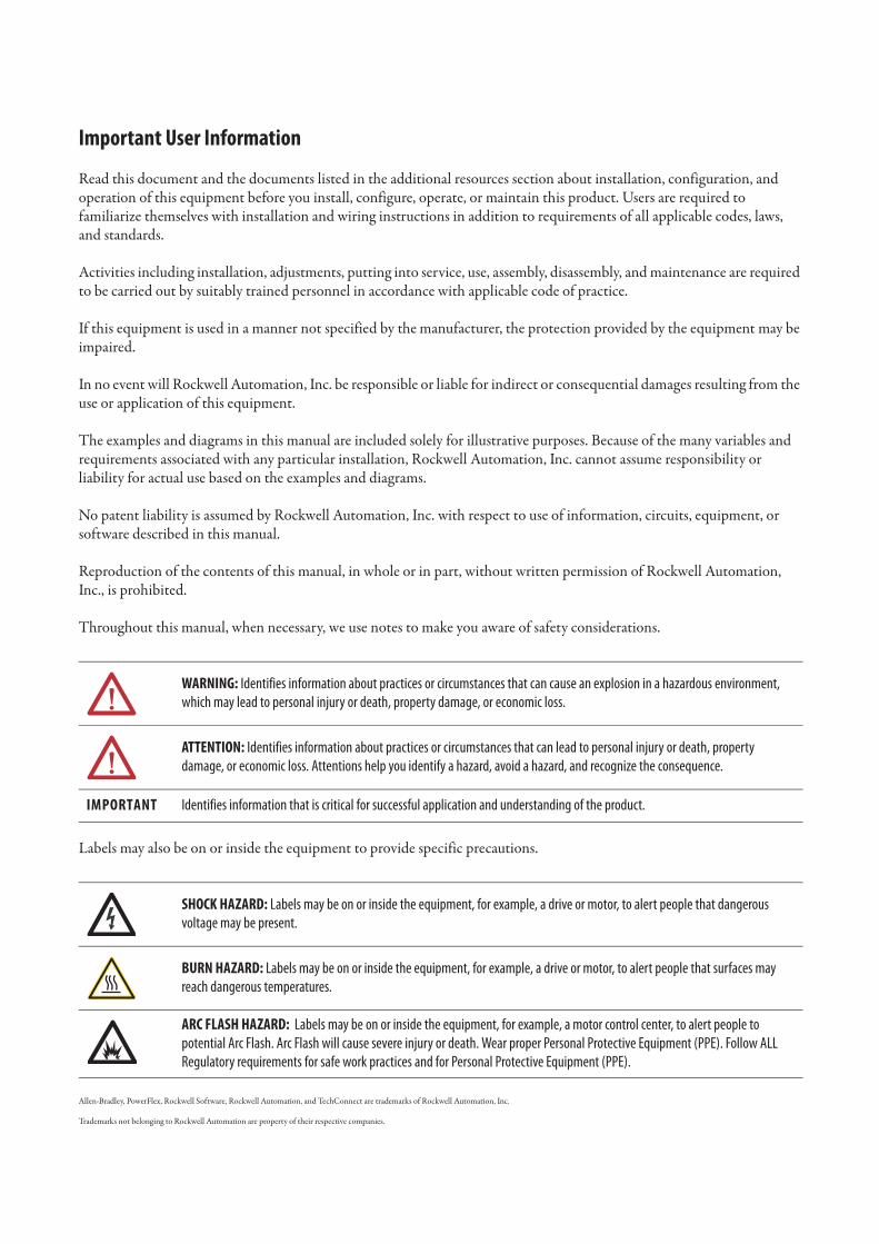
This manual contains new and updated information.
New and Updated Information
This table contains the changes made to this revision.
Topic Page
Added information on parts availability to Phase 3 - Starts January 1, 2015 in the Energy-related Products Fan Efficiency Directive section.
13
Add spare part information for the frame 9 drive fan bracket. 20
Updated the Frame 10 AFE Drive Configurations section to include a drawing and information on the IP20 NEMA / UL Type 1 (MCC) Cabinet.
186
Updated the DC Fan Systems spare parts table to include the new LCL filter fan DC power supply kit. 188
Updated the Frame 10 AFE (LCL Filter Section) DC Fan System Wiring Schematic Diagram to reflect the new LCL filter fan DC power supply kit.
191
Updated the LCL Filter Section table to include the new LCL filter fan DC power supply kit. 214
Added the LCL Filter DC Fan Power Supply Kit (SK-Y1-DCPS2-F10) Removal and Installation procedures for the new kit.
219
Added the LCL Filter DC Fan Power Supply Circuit Board (SK-H1-DCFANBD1) Removal and Installation procedures for the new kit.
225
Updated the LCL Filter Main DC Fan (SK-Y1-DCFAN1) Assembly Removal and Installation to include new steps.
230
Updated the DC Fan Systems spare parts table to include the new LCL filter fan DC power supply kit. 239
Updated the LCL Filter Fan DC Power Supply (SK-Y1-DCPS2-F13) Wiring Diagram - Newer Version to reflect the new LCL filter fan DC power supply kit.
247
Updated the LCL Filter Section table to include the new LCL filter fan DC power supply kit. 243
Added the LCL Filter Fan DC Power Supply (SK-Y1-DCPS2-F13) Removal and Installation procedures for the new kit.
247
Updated the Spare Part Kit Contents to include the new LCL filter fan DC power supply kits. 277
4 Rockwell Automation Publication PFLEX-IN029B-EN-P - August 2014
Summary of Changes
Notes:
Rockwell Automation Publication PFLEX-IN029B-EN-P - August 2014 5
Table of Contents
Preface Who Should Use this Manual . . . . . . . . . . . . . . . . . . . . . . . . . . . . . . . . . . . . . 11Verify Your Drive Frame Size . . . . . . . . . . . . . . . . . . . . . . . . . . . . . . . . . . . . . 11What is Not in this Manual . . . . . . . . . . . . . . . . . . . . . . . . . . . . . . . . . . . . . . . 12Energy-related Products Fan Efficiency Directive . . . . . . . . . . . . . . . . . . . 12
Phase 1 - Starts January 1, 2013 . . . . . . . . . . . . . . . . . . . . . . . . . . . . . . . . 12Phase 2 - Starts January 1, 2013, and Ending December 31, 2014 . 13Phase 3 - Starts January 1, 2015 . . . . . . . . . . . . . . . . . . . . . . . . . . . . . . . . 13Fan System Replacement FAQs. . . . . . . . . . . . . . . . . . . . . . . . . . . . . . . . 13Fan System Replacement Recommendations. . . . . . . . . . . . . . . . . . . . 14
How to Use this Manual. . . . . . . . . . . . . . . . . . . . . . . . . . . . . . . . . . . . . . . . . . 15Fastener/Tool/Torque Information . . . . . . . . . . . . . . . . . . . . . . . . . . . . . . . 16General Precautions . . . . . . . . . . . . . . . . . . . . . . . . . . . . . . . . . . . . . . . . . . . . . . 17
Qualified Personnel . . . . . . . . . . . . . . . . . . . . . . . . . . . . . . . . . . . . . . . . . . 17Personal Safety . . . . . . . . . . . . . . . . . . . . . . . . . . . . . . . . . . . . . . . . . . . . . . . 17Product Safety . . . . . . . . . . . . . . . . . . . . . . . . . . . . . . . . . . . . . . . . . . . . . . . 17Class 1 LED Product . . . . . . . . . . . . . . . . . . . . . . . . . . . . . . . . . . . . . . . . . 17
Chapter 1
PowerFlex 700H and 700S Drives -
Frame 9 Procedures
Frame 9 Fan System Spare Parts . . . . . . . . . . . . . . . . . . . . . . . . . . . . . . . . . . . 20AC Fan Systems . . . . . . . . . . . . . . . . . . . . . . . . . . . . . . . . . . . . . . . . . . . . . . 20DC Fan Systems. . . . . . . . . . . . . . . . . . . . . . . . . . . . . . . . . . . . . . . . . . . . . . 20
Tools Needed for Frame 9 Fan System Repairs. . . . . . . . . . . . . . . . . . . . . . 20Frame 9 Schematic Diagrams. . . . . . . . . . . . . . . . . . . . . . . . . . . . . . . . . . . . . . 21Frame 9 Fan System Replacement Procedures . . . . . . . . . . . . . . . . . . . . . . 22
Remove Power from the Drive. . . . . . . . . . . . . . . . . . . . . . . . . . . . . . . . . 23Remove the Lower Protective Cover . . . . . . . . . . . . . . . . . . . . . . . . . . . 24Remove the Upper Protective Cover . . . . . . . . . . . . . . . . . . . . . . . . . . . 24Removing the Main Fan Inverter Capacitor Bracket . . . . . . . . . . . . . 25Main Fan Fuses (20-PP20202) and Fuse Holder (20-PP20300) Removal and Installation. . . . . . . . . . . . . . . . . . . . . . . . . . . . . . . . . . . . . . 29Main Fan Inverter Cooling Fan (20-PP01049) Removal and Installation . . . . . . . . . . . . . . . . . . . . . . . . . . . . . . . . . . . . . . . . . . . . . . . . . . 30Main AC Fan Inverter Capacitor (SK-H1-FANCAP-F9) Removal and Installation . . . . . . . . . . . . . . . . . . . . . . . . . . . . . . . . . . . . . . . . . . . . . . 31Main AC Fan Inverter Circuit Board Assembly (20-VB00299) Removal and Installation. . . . . . . . . . . . . . . . . . . . . . . . . . . . . . . . . . . . . . 33Main DC Fan Power Supply Circuit Board (SK-H1-DCFANBD1) Removal and Installation. . . . . . . . . . . . . . . . . . . . . . . . . . . . . . . . . . . . . . 36AC to DC Fan System Retrofit Kit (SK-H1-DCFANRETROFIT-F9) . . . . . . . . . . . . . . . . . . . . . . . . . . . . . . . . . . . . . . . . . . . . . . . . . . . . . . . . . . 39Main AC Fan (20-PP01080) and Main DC Fan (SK-Y1-DCFAN1) Assembly Removal and Installation . . . . . . . . . . . . . . . . . . . . . . . . . . . . 43Main AC Fan Inverter Output Transformer (20-PP09055) Removal and Installation . . . . . . . . . . . . . . . . . . . . . . . . . . . . . . . . . . . . . . . . . . . . . . 49Chassis Stirring Fan (20-PP01068) Removal and Installation . . . . 50

6 Rockwell Automation Publication PFLEX-IN029B-EN-P - August 2014
Table of Contents
Cross-plate Stirring Fan (20-PP01068) Removal and Installation . 51Internal Stirring Fan (20-PP01068) Removal and Installation . . . . 52
Chapter 2
PowerFlex 700H and 700S Drives -
Frame 10 Procedures
Frame 10 Fan System Spare Parts . . . . . . . . . . . . . . . . . . . . . . . . . . . . . . . . . . 56AC Fan Systems . . . . . . . . . . . . . . . . . . . . . . . . . . . . . . . . . . . . . . . . . . . . . . 56DC Fan Systems . . . . . . . . . . . . . . . . . . . . . . . . . . . . . . . . . . . . . . . . . . . . . . 56
Tools Needed for Frame 10 Fan System Repairs. . . . . . . . . . . . . . . . . . . . . 56Frame 10 Schematic Diagrams. . . . . . . . . . . . . . . . . . . . . . . . . . . . . . . . . . . . . 57Frame 10 Fan System Replacement Procedures. . . . . . . . . . . . . . . . . . . . . . 59
Remove Power from the Drive . . . . . . . . . . . . . . . . . . . . . . . . . . . . . . . . . 59Move the Control Frame and Remove the Air Flow Plate and Protective Covers . . . . . . . . . . . . . . . . . . . . . . . . . . . . . . . . . . . . . . . . . . . . . 60Remove the Main AC or DC Fan Power Supply Assemblies . . . . . . 63Main AC Fan Inverter Circuit Board (20-VB00299) and AC Fan Output Transformer Assembly [20-FR10844 (Left) or 20-FR10845 (Right)] Removal and Installation. . . . . . . . . . . . . . . . . . . . . . . . . . . . . . 67Main DC Fan Power Supply System (SK-H1-DCFANBD1) Removal and Installation. . . . . . . . . . . . . . . . . . . . . . . . . . . . . . . . . . . . . . . . . . . . . . . 69AC to DC Fan System Retrofit Kit (SK-H1-DCFANRETROFIT-F10) . . . . . . . . . . . . . . . . . . . . . . . . . . . . . . . . . . . . . . . . . . . . . . . . . . . . . . . . . 70Main AC Fan Inverter Capacitor (SK-H1-FANCAP-F1012) Removal and Installation . . . . . . . . . . . . . . . . . . . . . . . . . . . . . . . . . . . . . . 74Main AC Fan (20-PP01080) and Main DC Fan (SK-Y1-DCFAN1) Assembly Removal and Installation. . . . . . . . . . . . . . . . . . . . . . . . . . . . . 78ASIC Circuit Board Assembly Cooling Fan (20-PP01096) Removal and Installation. . . . . . . . . . . . . . . . . . . . . . . . . . . . . . . . . . . . . . . . . . . . . . . 82AC or DC Fan System Fuses (20-PP20202) and Fuse Holder (20-PP20300) Removal and Installation . . . . . . . . . . . . . . . . . . . . . . . . . . . . 85
Chapter 3
PowerFlex 700H and 700S Drives -
Frame 11 Procedures
Frame 11 Fan System Spare Parts . . . . . . . . . . . . . . . . . . . . . . . . . . . . . . . . . . 88AC Fan Systems . . . . . . . . . . . . . . . . . . . . . . . . . . . . . . . . . . . . . . . . . . . . . . 88DC Fan Systems . . . . . . . . . . . . . . . . . . . . . . . . . . . . . . . . . . . . . . . . . . . . . . 88
Tools Needed for Frame 11 Fan System Repairs. . . . . . . . . . . . . . . . . . . . . 88Frame 11 Schematic Diagrams. . . . . . . . . . . . . . . . . . . . . . . . . . . . . . . . . . . . . 89Frame 11 Fan System Replacement Procedures. . . . . . . . . . . . . . . . . . . . . . 91
Remove Power from the Drive . . . . . . . . . . . . . . . . . . . . . . . . . . . . . . . . . 91Move the Control Frame and Remove the Air Flow Plate and Protective Covers . . . . . . . . . . . . . . . . . . . . . . . . . . . . . . . . . . . . . . . . . . . . . 92Removing the Main AC or DC Fan Power Supply Assemblies . . . . 95Main AC Fan Inverter Circuit Board (20-VB00299) and AC Output Transformer Assembly (20-FR10845) Removal and Installation . . 99Main DC Fan Power Supply Circuit Board (SK-H1-DCFANBD1) Removal and Installation . . . . . . . . . . . . . . . . . . . . . . . . . . . . . . . . . . . . . 101
Rockwell Automation Publication PFLEX-IN029B-EN-P - August 2014 7
Table of Contents
AC to DC Fan System Retrofit Kit (SK-H1-DCFANRETROFIT-F11). . . . . . . . . . . . . . . . . . . . . . . . . . . . . . . . . . . . . . . . . . . . . . . . . . . . . . . . 103Main AC Fan Inverter Capacitor (SK-H1-FANCAP-F11) Removal and Installation . . . . . . . . . . . . . . . . . . . . . . . . . . . . . . . . . . . . . . . . . . . . . 105Main AC Fan (20-PP01080) and Main DC Fan (SK-Y1-DCFAN1) Assembly Removal and Installation . . . . . . . . . . . . . . . . . . . . . . . . . . . 110ASIC Circuit Board Assembly Cooling Fan (20-PP01096) Removal and Installation . . . . . . . . . . . . . . . . . . . . . . . . . . . . . . . . . . . . . . . . . . . . . 113AC or DC Fan System Fuses (20-PP20202) and Fuse Holder (20-PP20300) Removal and Installation. . . . . . . . . . . . . . . . . . . . . . . . . . . 115
Chapter 4
PowerFlex 700H and 700S Drives -
Frame 12 Procedures
Frame 12 Fan System Spare Parts . . . . . . . . . . . . . . . . . . . . . . . . . . . . . . . . . 117AC Fan System Spare Parts. . . . . . . . . . . . . . . . . . . . . . . . . . . . . . . . . . . 118DC Fan System Spare Parts . . . . . . . . . . . . . . . . . . . . . . . . . . . . . . . . . . 118
Frame 12 Schematic Diagrams . . . . . . . . . . . . . . . . . . . . . . . . . . . . . . . . . . . 119
Chapter 5
PowerFlex 700H and 700S Drives -
Frame 13 Procedures
Frame 13 Drive Configurations . . . . . . . . . . . . . . . . . . . . . . . . . . . . . . . . . . 122Frame 13 Fan System Spare Parts . . . . . . . . . . . . . . . . . . . . . . . . . . . . . . . . . 123
AC Fan Systems . . . . . . . . . . . . . . . . . . . . . . . . . . . . . . . . . . . . . . . . . . . . . 123DC Fan Systems. . . . . . . . . . . . . . . . . . . . . . . . . . . . . . . . . . . . . . . . . . . . . 124
Tools Needed for Frame 13 Fan System Repairs . . . . . . . . . . . . . . . . . . . 125Frame 13 AFE Schematic Diagrams. . . . . . . . . . . . . . . . . . . . . . . . . . . . . . . 125Frame 13 Fan System Replacement Procedures . . . . . . . . . . . . . . . . . . . . 134
Remove Power from the Drive. . . . . . . . . . . . . . . . . . . . . . . . . . . . . . . . 134Move the Control Frame, and Remove the Screens, Airflow Plates, and Protective Covers. . . . . . . . . . . . . . . . . . . . . . . . . . . . . . . . . . . . . . . . . . . . 135Remove the Voltage Feedback Circuit Board Assembly (Inverter Only). . . . . . . . . . . . . . . . . . . . . . . . . . . . . . . . . . . . . . . . . . . . . . . . . . . . . . . 138ASIC Circuit Board Assembly Cooling Fan (20-PP01096) Removal and Installation (Inverter Only) . . . . . . . . . . . . . . . . . . . . . . . . . . . . . . 139AC or DC Fan System Fuses (20-PP20202) and Fuse Holder (20-PP20300) Removal and Installation. . . . . . . . . . . . . . . . . . . . . . . . . . . 141Remove the Main Fan Assembly . . . . . . . . . . . . . . . . . . . . . . . . . . . . . . 143Removing the Main AC or DC Fan Power Supply Assemblies (Inverter Only). . . . . . . . . . . . . . . . . . . . . . . . . . . . . . . . . . . . . . . . . . . . . . 145Main AC Fan Inverter Circuit Board (20-VB00299) and DC Fan Power Supply Circuit Board (SK-H1-DCFANBD1) Removal and Installation (Converter Only) . . . . . . . . . . . . . . . . . . . . . . . . . . . . . . . . 148Main AC Fan Inverter Circuit Board (20-VB00299) Removal and Installation (Inverter Only) . . . . . . . . . . . . . . . . . . . . . . . . . . . . . . . . . . 151Main DC Fan Power Supply Circuit Board (SK-H1-DCFANBD1) Removal and Installation (Inverter Only). . . . . . . . . . . . . . . . . . . . . . 153AC to DC Main Fan System (SK-x1-DCFANRETROFIT-F13x and -14x) Retrofit . . . . . . . . . . . . . . . . . . . . . . . . . . . . . . . . . . . . . . . . . . . . . . . 154
8 Rockwell Automation Publication PFLEX-IN029B-EN-P - August 2014
Table of Contents
Main AC Fan Inverter Capacitor (SK-H1-FANCAP-F1314) Removal and Installation (Converter Only). . . . . . . . . . . . . . . . . . . . 169Main AC Fan Inverter Capacitor (SK-H1-FANCAP-F1314) Removal and Installation (Inverter Only) . . . . . . . . . . . . . . . . . . . . . . 170Main AC Fan (20-FI13300) and Main DC Fan (SK-Y1-DCFAN1) Assembly Removal and Installation. . . . . . . . . . . . . . . . . . . . . . . . . . . . 174
Chapter 6
PowerFlex 700H and 700S Drives -
Frame 14 Procedures
Frame 14 Drive Configurations. . . . . . . . . . . . . . . . . . . . . . . . . . . . . . . . . . . 179Frame 14 Fan System Spare Parts . . . . . . . . . . . . . . . . . . . . . . . . . . . . . . . . . 179
AC Fan Systems . . . . . . . . . . . . . . . . . . . . . . . . . . . . . . . . . . . . . . . . . . . . . 180DC Fan Systems . . . . . . . . . . . . . . . . . . . . . . . . . . . . . . . . . . . . . . . . . . . . . 181
Frame 14 System Diagrams. . . . . . . . . . . . . . . . . . . . . . . . . . . . . . . . . . . . . . . 182
Chapter 7
PowerFlex 700AFE Drive - Frame 10
Procedures
Frame 10 AFE Drive Configurations . . . . . . . . . . . . . . . . . . . . . . . . . . . . . . 186Frame 10 AFE Fan System Spare Parts . . . . . . . . . . . . . . . . . . . . . . . . . . . . 187
AC Fan Systems . . . . . . . . . . . . . . . . . . . . . . . . . . . . . . . . . . . . . . . . . . . . . 187DC Fan Systems . . . . . . . . . . . . . . . . . . . . . . . . . . . . . . . . . . . . . . . . . . . . . 188
Tools Needed for Frame 10 AFE Fan System Repairs . . . . . . . . . . . . . . . 188Frame 10 AFE Fan System Schematic Diagrams. . . . . . . . . . . . . . . . . . . . 189Frame 10 AFE Fan System Replacement Procedures. . . . . . . . . . . . . . . . 192
Power Structure Section. . . . . . . . . . . . . . . . . . . . . . . . . . . . . . . . . . . . . . 192LCL Filter Section . . . . . . . . . . . . . . . . . . . . . . . . . . . . . . . . . . . . . . . . . . . 214
Chapter 8
PowerFlex 700AFE Drive - Frame 13
Procedures
Frame 13 AFE Drive Configurations . . . . . . . . . . . . . . . . . . . . . . . . . . . . . . 236Frame 13 AFE Fan System Spare Parts . . . . . . . . . . . . . . . . . . . . . . . . . . . . 238
AC Fan Systems . . . . . . . . . . . . . . . . . . . . . . . . . . . . . . . . . . . . . . . . . . . . . 238DC Fan Systems . . . . . . . . . . . . . . . . . . . . . . . . . . . . . . . . . . . . . . . . . . . . . 239
Tools Needed for Frame 13 AFE Fan System Repairs . . . . . . . . . . . . . . . 239Frame 13 AFE Schematic Diagrams . . . . . . . . . . . . . . . . . . . . . . . . . . . . . . . 240Frame 13 AFE Fan System Replacement Procedures. . . . . . . . . . . . . . . . 243
Power Structure Section. . . . . . . . . . . . . . . . . . . . . . . . . . . . . . . . . . . . . . 243LCL Filter Section . . . . . . . . . . . . . . . . . . . . . . . . . . . . . . . . . . . . . . . . . . . 243
Appendix A
PowerFlex 700H and 700S Diagnostic
Procedures
Qualified Personnel . . . . . . . . . . . . . . . . . . . . . . . . . . . . . . . . . . . . . . . . . 256Personal Safety . . . . . . . . . . . . . . . . . . . . . . . . . . . . . . . . . . . . . . . . . . . . . . 256Product Safety. . . . . . . . . . . . . . . . . . . . . . . . . . . . . . . . . . . . . . . . . . . . . . . 256Class 1 LED Product . . . . . . . . . . . . . . . . . . . . . . . . . . . . . . . . . . . . . . . . 256
Fan Inverter System Block Diagrams . . . . . . . . . . . . . . . . . . . . . . . . . . . . . . 257AC Fan Inverter System . . . . . . . . . . . . . . . . . . . . . . . . . . . . . . . . . . . . . . 257DC Fan System. . . . . . . . . . . . . . . . . . . . . . . . . . . . . . . . . . . . . . . . . . . . . . 257PowerFlex 700H and PowerFlex 700S Drives . . . . . . . . . . . . . . . . . . 257
Rockwell Automation Publication PFLEX-IN029B-EN-P - August 2014 9
Table of Contents
PowerFlex 700AFE . . . . . . . . . . . . . . . . . . . . . . . . . . . . . . . . . . . . . . . . . . 259Checking the Fan Inverter Fuses. . . . . . . . . . . . . . . . . . . . . . . . . . . . . . . . . . 263
Checking Fuse Integrity with no Power Applied . . . . . . . . . . . . . . . 263Checking Fuse Integrity with Power Applied . . . . . . . . . . . . . . . . . . 263
Checking the Main Fan Supply Wires . . . . . . . . . . . . . . . . . . . . . . . . . . . . 264Checking the AC Fan Inverter Capacitor . . . . . . . . . . . . . . . . . . . . . . . . . 265Isolating a Faulty Fan Inverter. . . . . . . . . . . . . . . . . . . . . . . . . . . . . . . . . . . . 265
Frame 9 PowerFlex 700H and 700S Drives . . . . . . . . . . . . . . . . . . . . 265Frames 10 and 12 PowerFlex 700H and 700S Drives . . . . . . . . . . . 265Frame 11 PowerFlex 700H and 700S Drives . . . . . . . . . . . . . . . . . . . 267Frames 13 and 14 PowerFlex 700H and 700S Drives . . . . . . . . . . . 268Frames 10 and 13 PowerFlex 700AFE . . . . . . . . . . . . . . . . . . . . . . . . . 268
Checking the Main AC Fan Inverter Circuit Board Diagnostic LEDs 268AC Fan System LEDs. . . . . . . . . . . . . . . . . . . . . . . . . . . . . . . . . . . . . . . . 269DC Fan System LEDs . . . . . . . . . . . . . . . . . . . . . . . . . . . . . . . . . . . . . . . 269Fan System Wiring and Operation . . . . . . . . . . . . . . . . . . . . . . . . . . . . 270
Testing the Main Fan Inverter Circuit Board Diagnostic LEDs . . . . . 274AC Fan System Test . . . . . . . . . . . . . . . . . . . . . . . . . . . . . . . . . . . . . . . . . 275DC Fan System Test. . . . . . . . . . . . . . . . . . . . . . . . . . . . . . . . . . . . . . . . . 276
Appendix B
Available Fan System Kits Spare Part Kit Contents . . . . . . . . . . . . . . . . . . . . . . . . . . . . . . . . . . . . . . . . . 277

10 Rockwell Automation Publication PFLEX-IN029B-EN-P - August 2014
Table of Contents
Rockwell Automation Publication PFLEX-IN029B-EN-P - August 2014 11
Preface
This manual contains fan system service information for frame 9…14 PowerFlex 700H and PowerFlex 700S AC drives, and the frame 10 and 13 PowerFlex 700AFE.
Who Should Use this Manual This manual is intended for qualified service personnel responsible for troubleshooting and repairing frame 9…14 PowerFlex 700H and 700S and frame 10 and 13 PowerFlex 700AFE drives. You must have previous experience with, and a basic understanding of, electrical terminology, procedures, required troubleshooting equipment, equipment protection procedures and methods, and safety precautions to make repairs on these drives and use this manual.
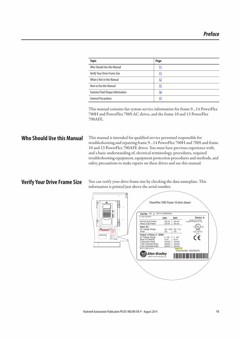
Verify Your Drive Frame Size You can verify your drive frame size by checking the data nameplate. This information is printed just above the serial number.
Topic Page
Who Should Use this Manual 11
Verify Your Drive Frame Size 11
What is Not in this Manual 12
How to Use this Manual 15
Fastener/Tool/Torque Information 16
General Precautions 17
Cat No. 20D J 300 N 0 NNNBNNNNUL Open Type/IP00 540V 650VNormal Duty Power 160 kW
132 kW250 kW200 kWHeavy Duty Power
DC Voltage Range 462 - 594350
583 - 713350Amps
Input: DC,
AC Voltage Range 0 - 40050 Hz
0 - 46060 HzBase Hz (default)
Output: 3 Phase, 0 - 320Hz
Continuous Amps 300/245330/368
300/245330/3681 Min Overload Amps
2 Sec Overload Amps 450/490 450/490MFD. in 1989 on Nov 9
Serial Number: 2622381652
MADE IN THE USA (FAC 1B)
Series: AStandard I/O: NONE
Original Firmware No. 2.04
UL USC Æ
LISTEDIND CONT EQ
Cat No. 20D J 500 N 0 NNNBNNNNUL Open Type/IP00 540V 650VNormal Duty Power 250 kW
200 kW450 kW500 kWHeavy Duty Power
DC Voltage Range 462 - 594350
583 - 713350Amps
Input: DC,
AC Voltage Range 0 - 40050 Hz
0 - 46060 HzBase Hz (default)
Output: 3 Phase, 0 - 320Hz
Continuous Amps 420/500630/550
420/500630/5501 Min Overload Amps
2 Sec Overload Amps 840/630 840/630MFD. in 1989 on Nov 9 Frame #: 10
Serial Number: 2622381652
MADE IN THE USA (FAC 1B)
Series: AStandard I/O: NONE
Original Firmware No. 2.04
UL USC Æ
LISTEDIND CONT EQ
9D42
Frame #: 10
PowerFlex 700S Frame 10 drive shown

12 Rockwell Automation Publication PFLEX-IN029B-EN-P - August 2014
Preface
What is Not in this Manual This manual does not contain information about parts and functions of the drive that are not related to fan system service within the drive. For more information and service procedures for your particular drive, see the applicable publication in this table.
You can view or download publications athttp://www.rockwellautomation.com/literature/. To order paper copies of technical documentation, contact your local Allen-Bradley distributor or Rockwell Automation sales representative.
Energy-related Products Fan Efficiency Directive
The Energy-related Products (ErP) Directive (2012/27/EU on Energy Efficiency, 25, October 2012) is the European Commission Directive required for products sold and exported to the European Union (EU). This directive aims to protect the environment by increasing energy efficiency in the EU. This directive, among other things, defines the minimum efficiency for fans in the range of 0.125…500 kW.
For PowerFlex 700H and 700S drive fan systems, this directive will be implemented in multiple phases.
Phase 1 - Starts January 1, 2013
New products delivered within the EU (with a power structure manufacture date of January 1, 2013 and later) will have a DC fan system installed. Phase I includes PowerFlex 700H and 700S frame 9 and larger drives and PowerFlex 700AFE systems.
DC fan system kits have been developed to support the repair of damaged units and to provide retrofit solutions. However, the ErP Directive does not require drives with existing AC fan systems to be retrofitted.
Drive Type Frame Size Publication Title Publication Number
PowerFlex 700H and 700S
9 PowerFlex 700H/S Drives, Frame 9 Hardware Service Manual
PFLEX-TG001
10 PowerFlex 700H/S Drives, Frame 10 Hardware Service Manual
PFLEX-TG002
11 PowerFlex 700H/S Drives, Frame 11 Hardware Service Manual
PFLEX-TG003
12 PowerFlex 700H/S Drives, Frame 12 Hardware Service Manual
PFLEX-TG004
13 PowerFlex 700H/S Drives, Frame 13 Hardware Service Manual
PFLEX-TG005
14 PowerFlex 700H/S Drives, Frame 14 Hardware Service Manual
PFLEX-TG006
PowerFlex 700AFE 10 PowerFlex 700AFE Frame 10 Hardware Service Manual
20Y-TG001
13 PowerFlex 700AFE Frame 13 Hardware Service Manual
20Y-TG002
Rockwell Automation Publication PFLEX-IN029B-EN-P - August 2014 13
Preface
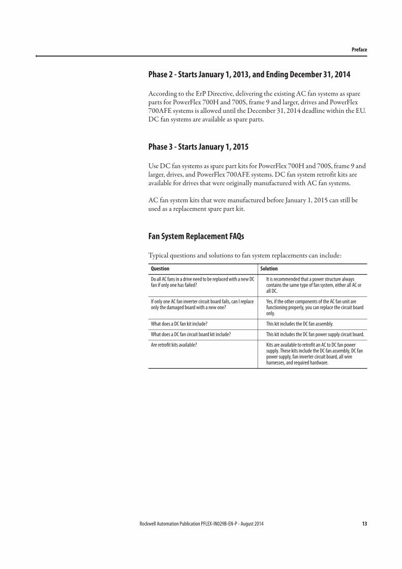
Phase 2 - Starts January 1, 2013, and Ending December 31, 2014
According to the ErP Directive, delivering the existing AC fan systems as spare parts for PowerFlex 700H and 700S, frame 9 and larger, drives and PowerFlex 700AFE systems is allowed until the December 31, 2014 deadline within the EU. DC fan systems are available as spare parts.
Phase 3 - Starts January 1, 2015
Use DC fan systems as spare part kits for PowerFlex 700H and 700S, frame 9 and larger, drives, and PowerFlex 700AFE systems. DC fan system retrofit kits are available for drives that were originally manufactured with AC fan systems.
AC fan system kits that were manufactured before January 1, 2015 can still be used as a replacement spare part kit.
Fan System Replacement FAQs
Typical questions and solutions to fan system replacements can include:
Question Solution
Do all AC fans in a drive need to be replaced with a new DC fan if only one has failed?
It is recommended that a power structure always contains the same type of fan system, either all AC or all DC.
If only one AC fan inverter circuit board fails, can I replace only the damaged board with a new one?
Yes, if the other components of the AC fan unit are functioning properly, you can replace the circuit board only.
What does a DC fan kit include? This kit includes the DC fan assembly.
What does a DC fan circuit board kit include? This kit includes the DC fan power supply circuit board.
Are retrofit kits available? Kits are available to retrofit an AC to DC fan power supply. These kits include the DC fan assembly, DC fan power supply, fan inverter circuit board, all wire harnesses, and required hardware.
14 Rockwell Automation Publication PFLEX-IN029B-EN-P - August 2014
Preface
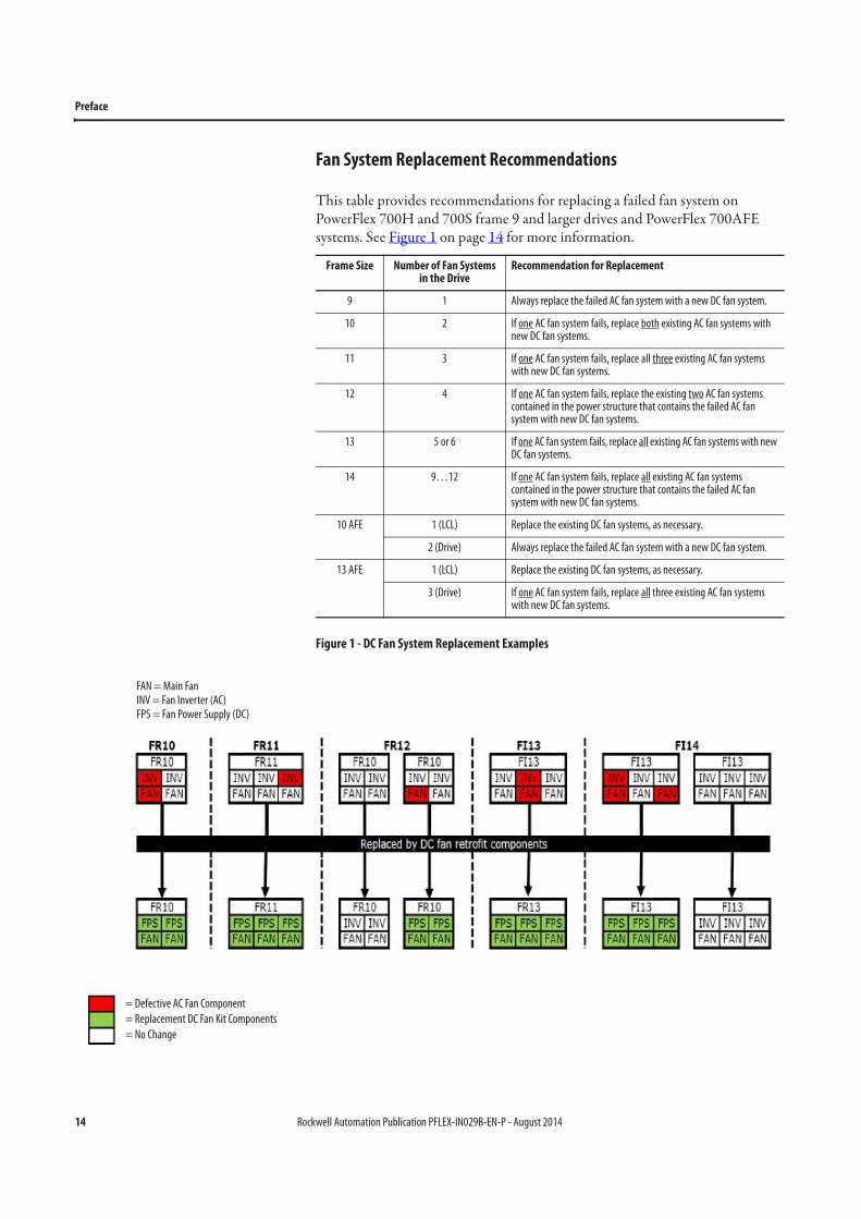
Fan System Replacement Recommendations
This table provides recommendations for replacing a failed fan system on PowerFlex 700H and 700S frame 9 and larger drives and PowerFlex 700AFE systems. See Figure 1 on page 14 for more information.
Figure 1 - DC Fan System Replacement Examples
Frame Size Number of Fan Systems in the Drive
Recommendation for Replacement
9 1 Always replace the failed AC fan system with a new DC fan system.
10 2 If one AC fan system fails, replace both existing AC fan systems with new DC fan systems.
11 3 If one AC fan system fails, replace all three existing AC fan systems with new DC fan systems.
12 4 If one AC fan system fails, replace the existing two AC fan systems contained in the power structure that contains the failed AC fan system with new DC fan systems.
13 5 or 6 If one AC fan system fails, replace all existing AC fan systems with new DC fan systems.
14 9…12 If one AC fan system fails, replace all existing AC fan systems contained in the power structure that contains the failed AC fan system with new DC fan systems.
10 AFE 1 (LCL) Replace the existing DC fan systems, as necessary.
2 (Drive) Always replace the failed AC fan system with a new DC fan system.
13 AFE 1 (LCL) Replace the existing DC fan systems, as necessary.
3 (Drive) If one AC fan system fails, replace all three existing AC fan systems with new DC fan systems.
FAN = Main FanINV = Fan Inverter (AC)FPS = Fan Power Supply (DC)
= Defective AC Fan Component
= Replacement DC Fan Kit Components
= No Change
Rockwell Automation Publication PFLEX-IN029B-EN-P - August 2014 15
Preface
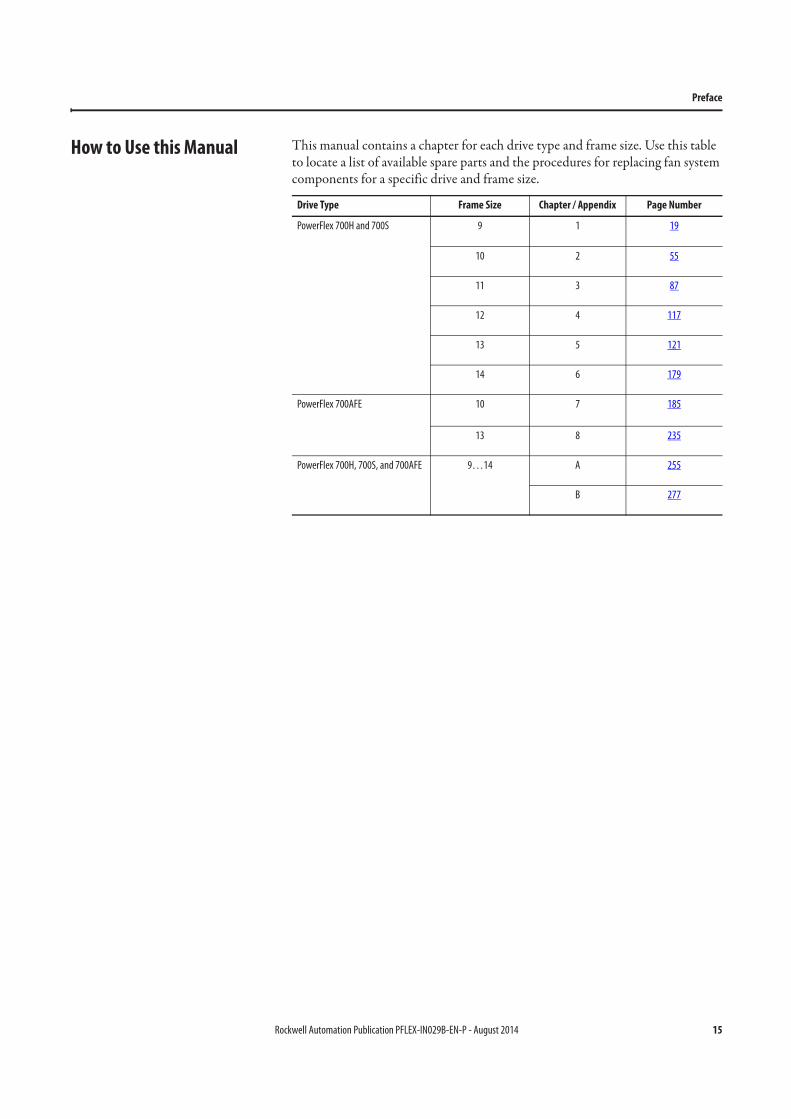
How to Use this Manual This manual contains a chapter for each drive type and frame size. Use this table to locate a list of available spare parts and the procedures for replacing fan system components for a specific drive and frame size.
Drive Type Frame Size Chapter / Appendix Page Number
PowerFlex 700H and 700S 9 1 19
10 2 55
11 3 87
12 4 117
13 5 121
14 6 179
PowerFlex 700AFE 10 7 185
13 8 235
PowerFlex 700H, 700S, and 700AFE 9…14 A 255
B 277
16 Rockwell Automation Publication PFLEX-IN029B-EN-P - August 2014
Preface
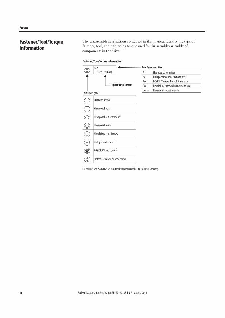
Fastener/Tool/Torque Information
The disassembly illustrations contained in this manual identify the type of fastener, tool, and tightening torque used for disassembly/assembly of components in the drive.
(1) Phillips® and POZIDRIV® are registered trademarks of the Phillips Screw Company.
Tool Type and Size:
F Flat nose screw driver
Px Phillips screw driver/bit and size
PZx POZIDRIV screw driver/bit and size
Txx Hexalobular screw driver/bit and size
xx mm Hexagonal socket wrench
Tightening Torque
Fastener Type:
Flat head screw
Hexagonal bolt
Hexagonal nut or standoff
Hexagonal screw
Hexalobular head screw
Phillips head screw (1)
POZIDRIV head screw (1)
Slotted Hexalobular head screw
Fastener/Tool/Torque Information:
PZ2
3.0 N•m (27 lb•in)
Rockwell Automation Publication PFLEX-IN029B-EN-P - August 2014 17
Preface
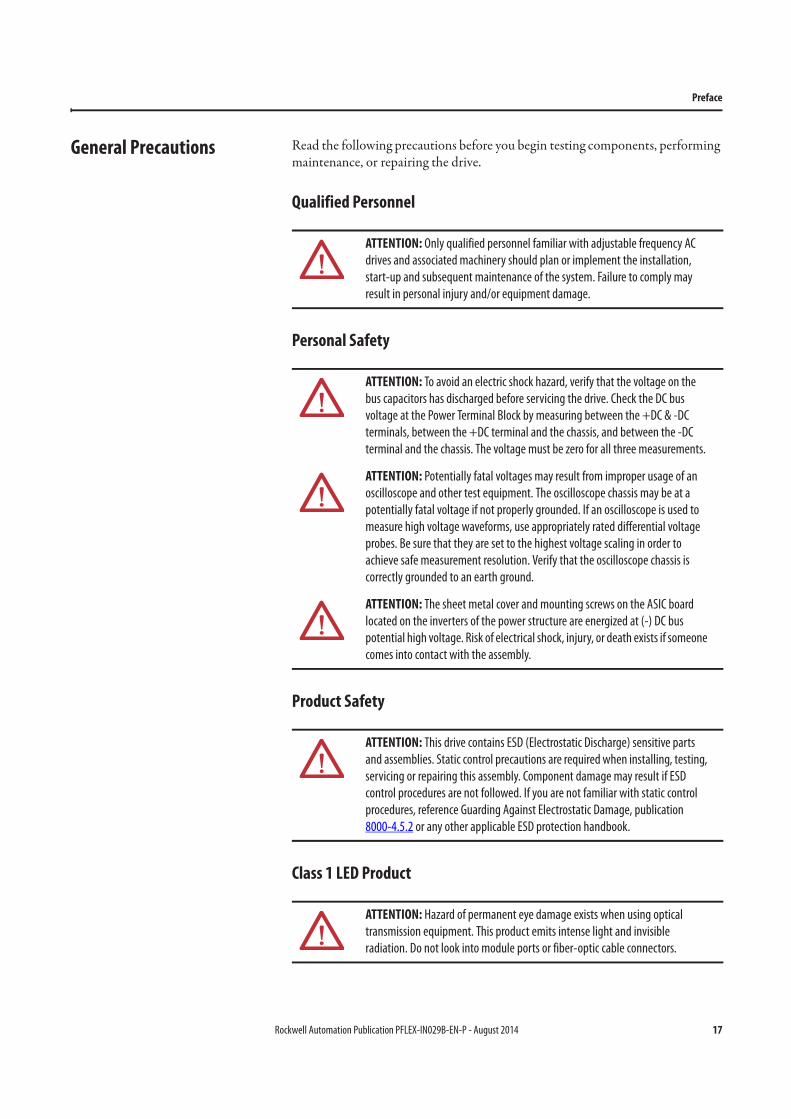
General Precautions Read the following precautions before you begin testing components, performing maintenance, or repairing the drive.
Qualified Personnel
Personal Safety
Product Safety
Class 1 LED Product
ATTENTION: Only qualified personnel familiar with adjustable frequency AC
drives and associated machinery should plan or implement the installation,
start-up and subsequent maintenance of the system. Failure to comply may
result in personal injury and/or equipment damage.
ATTENTION: To avoid an electric shock hazard, verify that the voltage on the
bus capacitors has discharged before servicing the drive. Check the DC bus
voltage at the Power Terminal Block by measuring between the +DC & -DC
terminals, between the +DC terminal and the chassis, and between the -DC
terminal and the chassis. The voltage must be zero for all three measurements.
ATTENTION: Potentially fatal voltages may result from improper usage of an
oscilloscope and other test equipment. The oscilloscope chassis may be at a
potentially fatal voltage if not properly grounded. If an oscilloscope is used to
measure high voltage waveforms, use appropriately rated differential voltage
probes. Be sure that they are set to the highest voltage scaling in order to
achieve safe measurement resolution. Verify that the oscilloscope chassis is
correctly grounded to an earth ground.
ATTENTION: The sheet metal cover and mounting screws on the ASIC board
located on the inverters of the power structure are energized at (-) DC bus
potential high voltage. Risk of electrical shock, injury, or death exists if someone
comes into contact with the assembly.
ATTENTION: This drive contains ESD (Electrostatic Discharge) sensitive parts
and assemblies. Static control precautions are required when installing, testing,
servicing or repairing this assembly. Component damage may result if ESD
control procedures are not followed. If you are not familiar with static control
procedures, reference Guarding Against Electrostatic Damage, publication
8000-4.5.2 or any other applicable ESD protection handbook.
ATTENTION: Hazard of permanent eye damage exists when using optical
transmission equipment. This product emits intense light and invisible
radiation. Do not look into module ports or fiber-optic cable connectors.
18 Rockwell Automation Publication PFLEX-IN029B-EN-P - August 2014
Preface
Notes:
Rockwell Automation Publication PFLEX-IN029B-EN-P - August 2014 19
Chapter 1
PowerFlex 700H and 700S Drives - Frame 9 Procedures
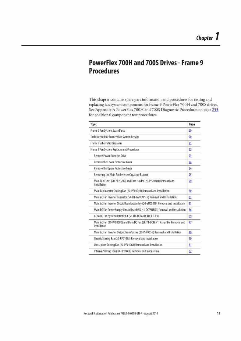
This chapter contains spare part information and procedures for testing and replacing fan system components for frame 9 PowerFlex 700H and 700S drives. See Appendix A PowerFlex 700H and 700S Diagnostic Procedures on page 255 for additional component test procedures.
Topic Page
Frame 9 Fan System Spare Parts 20
Tools Needed for Frame 9 Fan System Repairs 20
Frame 9 Schematic Diagrams 21
Frame 9 Fan System Replacement Procedures 22
Remove Power from the Drive 23
Remove the Lower Protective Cover 24
Remove the Upper Protective Cover 24
Removing the Main Fan Inverter Capacitor Bracket 25
Main Fan Fuses (20-PP20202) and Fuse Holder (20-PP20300) Removal and Installation
29
Main Fan Inverter Cooling Fan (20-PP01049) Removal and Installation 30
Main AC Fan Inverter Capacitor (SK-H1-FANCAP-F9) Removal and Installation 31
Main AC Fan Inverter Circuit Board Assembly (20-VB00299) Removal and Installation 33
Main DC Fan Power Supply Circuit Board (SK-H1-DCFANBD1) Removal and Installation 36
AC to DC Fan System Retrofit Kit (SK-H1-DCFANRETROFIT-F9) 39
Main AC Fan (20-PP01080) and Main DC Fan (SK-Y1-DCFAN1) Assembly Removal and Installation
43
Main AC Fan Inverter Output Transformer (20-PP09055) Removal and Installation 49
Chassis Stirring Fan (20-PP01068) Removal and Installation 50
Cross-plate Stirring Fan (20-PP01068) Removal and Installation 51
Internal Stirring Fan (20-PP01068) Removal and Installation 52
20 Rockwell Automation Publication PFLEX-IN029B-EN-P - August 2014
Chapter 1 PowerFlex 700H and 700S Drives - Frame 9 Procedures
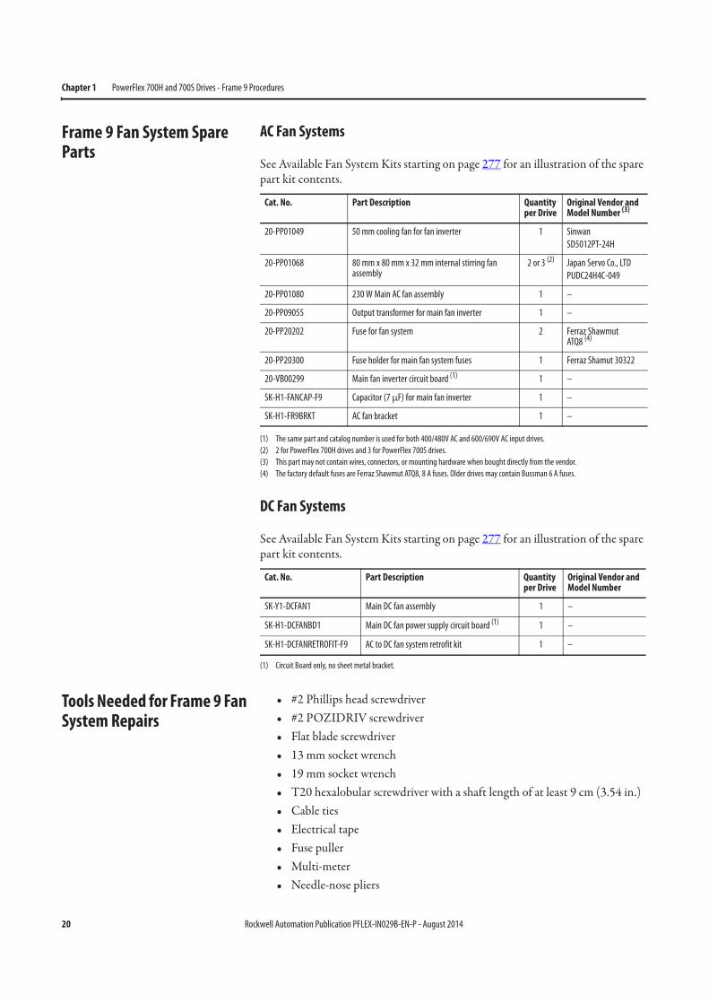
Frame 9 Fan System Spare Parts
AC Fan Systems
See Available Fan System Kits starting on page 277 for an illustration of the spare part kit contents.
DC Fan Systems
See Available Fan System Kits starting on page 277 for an illustration of the spare part kit contents.
Tools Needed for Frame 9 Fan System Repairs
• #2 Phillips head screwdriver• #2 POZIDRIV screwdriver• Flat blade screwdriver• 13 mm socket wrench• 19 mm socket wrench• T20 hexalobular screwdriver with a shaft length of at least 9 cm (3.54 in.)• Cable ties• Electrical tape• Fuse puller• Multi-meter• Needle-nose pliers
Cat. No. Part Description Quantity per Drive
Original Vendor and Model Number (3)
(3) This part may not contain wires, connectors, or mounting hardware when bought directly from the vendor.
20-PP01049 50 mm cooling fan for fan inverter 1 Sinwan
SD5012PT-24H
20-PP01068 80 mm x 80 mm x 32 mm internal stirring fan assembly
2 or 3 (2)
(2) 2 for PowerFlex 700H drives and 3 for PowerFlex 700S drives.
Japan Servo Co., LTD
PUDC24H4C-049
20-PP01080 230 W Main AC fan assembly 1 –
20-PP09055 Output transformer for main fan inverter 1 –
20-PP20202 Fuse for fan system 2 Ferraz ShawmutATQ8 (4)
(4) The factory default fuses are Ferraz Shawmut ATQ8, 8 A fuses. Older drives may contain Bussman 6 A fuses.
20-PP20300 Fuse holder for main fan system fuses 1 Ferraz Shamut 30322
20-VB00299 Main fan inverter circuit board (1)
(1) The same part and catalog number is used for both 400/480V AC and 600/690V AC input drives.
1 –
SK-H1-FANCAP-F9 Capacitor (7 μF) for main fan inverter 1 –
SK-H1-FR9BRKT AC fan bracket 1 –
Cat. No. Part Description Quantity per Drive
Original Vendor and Model Number
SK-Y1-DCFAN1 Main DC fan assembly 1 –
SK-H1-DCFANBD1 Main DC fan power supply circuit board (1)
(1) Circuit Board only, no sheet metal bracket.
1 –
SK-H1-DCFANRETROFIT-F9 AC to DC fan system retrofit kit 1 –
Rockwell Automation Publication PFLEX-IN029B-EN-P - August 2014 21
PowerFlex 700H and 700S Drives - Frame 9 Procedures Chapter 1
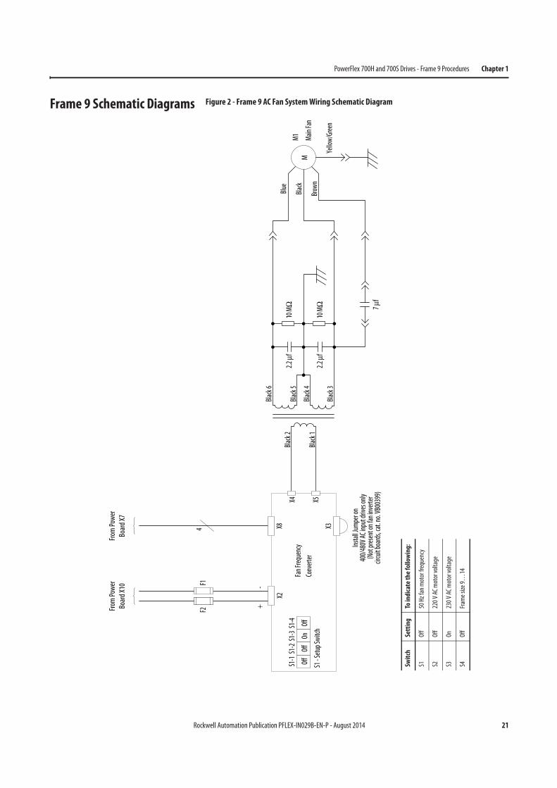
Frame 9 Schematic Diagrams Figure 2 - Frame 9 AC Fan System Wiring Schematic Diagram
X8
F2
X2
4
Fan
Frequency
Converter
+-
OffS1-1
OffS1-2
OnS1-3
OffS1-4
S1 - Setup Switch
F1
From
Power
Board X10
From
Power
Board X7
M1
Brown
Black
Blue
Main
Fan
M
Black 6
Black 5
Black 4
Black 3
Black 2
Black 1
X4 X5
2.2
f10
M
2.2
f10
M
Yellow/Green
7 f
X3
Instal
l Jum
per on
400/480V
AC input drives
only
(Not
present
on fan inverter
circuit boards, cat. no.
VB00399)
Swit
chSe
ttin
gTo
indi
cate
th
e fo
llow
ing:
S1O
ff50
Hz
fan
mot
or fr
eque
ncy
S2O
ff22
0 V
AC m
otor
vol
tage
S3O
n23
0 V
AC m
otor
vol
tage
S4O
ffFr
ame
size
9…
14
22 Rockwell Automation Publication PFLEX-IN029B-EN-P - August 2014
Chapter 1 PowerFlex 700H and 700S Drives - Frame 9 Procedures
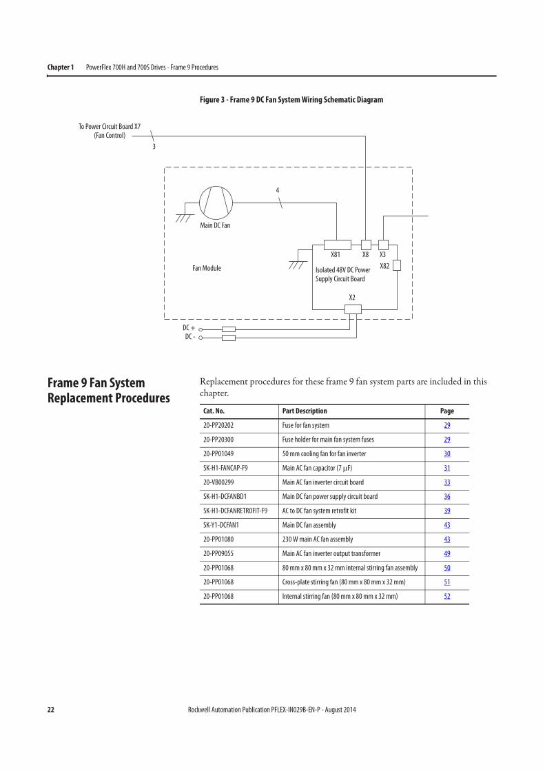
Figure 3 - Frame 9 DC Fan System Wiring Schematic Diagram
Frame 9 Fan System Replacement Procedures
Replacement procedures for these frame 9 fan system parts are included in this chapter.
To Power Circuit Board X7(Fan Control)
3
4
Main DC Fan
Fan Module
DC +DC -
Isolated 48V DC Power Supply Circuit Board
X81 X8 X3
X82
X2
Cat. No. Part Description Page
20-PP20202 Fuse for fan system 29
20-PP20300 Fuse holder for main fan system fuses 29
20-PP01049 50 mm cooling fan for fan inverter 30
SK-H1-FANCAP-F9 Main AC fan capacitor (7 μF) 31
20-VB00299 Main AC fan inverter circuit board 33
SK-H1-DCFANBD1 Main DC fan power supply circuit board 36
SK-H1-DCFANRETROFIT-F9 AC to DC fan system retrofit kit 39
SK-Y1-DCFAN1 Main DC fan assembly 43
20-PP01080 230 W main AC fan assembly 43
20-PP09055 Main AC fan inverter output transformer 49
20-PP01068 80 mm x 80 mm x 32 mm internal stirring fan assembly 50
20-PP01068 Cross-plate stirring fan (80 mm x 80 mm x 32 mm) 51
20-PP01068 Internal stirring fan (80 mm x 80 mm x 32 mm) 52
Rockwell Automation Publication PFLEX-IN029B-EN-P - August 2014 23
PowerFlex 700H and 700S Drives - Frame 9 Procedures Chapter 1
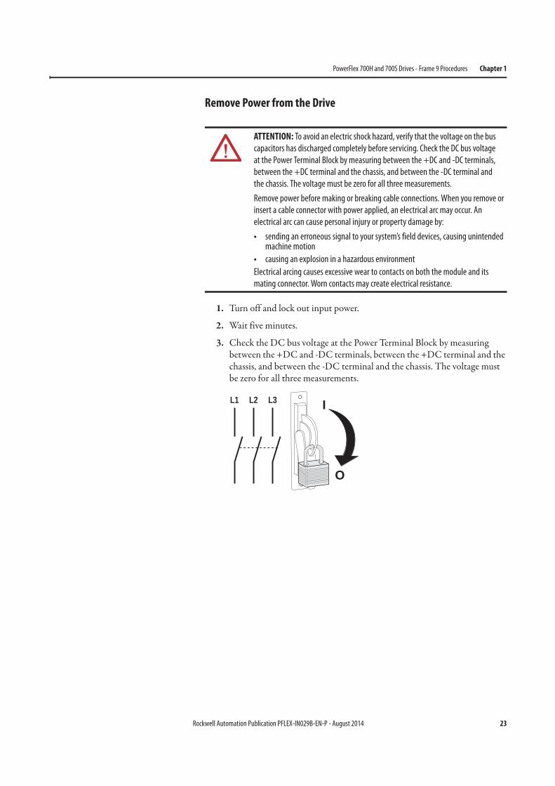
Remove Power from the Drive
1. Turn off and lock out input power.
2. Wait five minutes.
3. Check the DC bus voltage at the Power Terminal Block by measuring between the +DC and -DC terminals, between the +DC terminal and the chassis, and between the -DC terminal and the chassis. The voltage must be zero for all three measurements.
ATTENTION: To avoid an electric shock hazard, verify that the voltage on the bus
capacitors has discharged completely before servicing. Check the DC bus voltage
at the Power Terminal Block by measuring between the +DC and -DC terminals,
between the +DC terminal and the chassis, and between the -DC terminal and
the chassis. The voltage must be zero for all three measurements.
Remove power before making or breaking cable connections. When you remove or
insert a cable connector with power applied, an electrical arc may occur. An
electrical arc can cause personal injury or property damage by:
• sending an erroneous signal to your system’s field devices, causing unintended machine motion
• causing an explosion in a hazardous environment
Electrical arcing causes excessive wear to contacts on both the module and its
mating connector. Worn contacts may create electrical resistance.
L1 L2 L3
O
I
24 Rockwell Automation Publication PFLEX-IN029B-EN-P - August 2014
Chapter 1 PowerFlex 700H and 700S Drives - Frame 9 Procedures
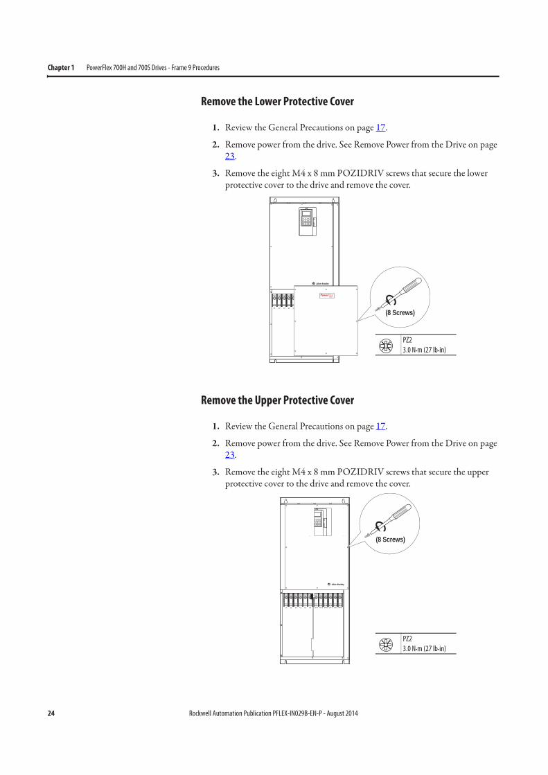
Remove the Lower Protective Cover
1. Review the General Precautions on page 17.
2. Remove power from the drive. See Remove Power from the Drive on page 23.
3. Remove the eight M4 x 8 mm POZIDRIV screws that secure the lower protective cover to the drive and remove the cover.
Remove the Upper Protective Cover
1. Review the General Precautions on page 17.
2. Remove power from the drive. See Remove Power from the Drive on page 23.
3. Remove the eight M4 x 8 mm POZIDRIV screws that secure the upper protective cover to the drive and remove the cover.
(8 Screws)L1 L2 L3 L1 L2 L3 U/T1 V/T2 W/T3 U/T1 V/T2 W/T3
PZ2
3.0 N•m (27 lb•in)
L1 L2 L3 L1 L2 L3 U/T1 V/T2 W/T3 U/T1 V/T2 W/T3
(8 Screws)
PZ2
3.0 N•m (27 lb•in)
Rockwell Automation Publication PFLEX-IN029B-EN-P - August 2014 25
PowerFlex 700H and 700S Drives - Frame 9 Procedures Chapter 1
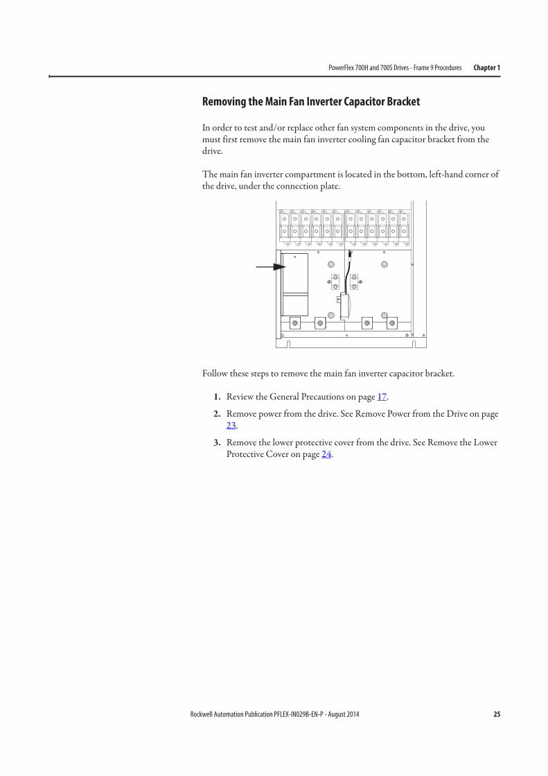
Removing the Main Fan Inverter Capacitor Bracket
In order to test and/or replace other fan system components in the drive, you must first remove the main fan inverter cooling fan capacitor bracket from the drive.
The main fan inverter compartment is located in the bottom, left-hand corner of the drive, under the connection plate.
Follow these steps to remove the main fan inverter capacitor bracket.
1. Review the General Precautions on page 17.
2. Remove power from the drive. See Remove Power from the Drive on page 23.
3. Remove the lower protective cover from the drive. See Remove the Lower Protective Cover on page 24.
26 Rockwell Automation Publication PFLEX-IN029B-EN-P - August 2014
Chapter 1 PowerFlex 700H and 700S Drives - Frame 9 Procedures
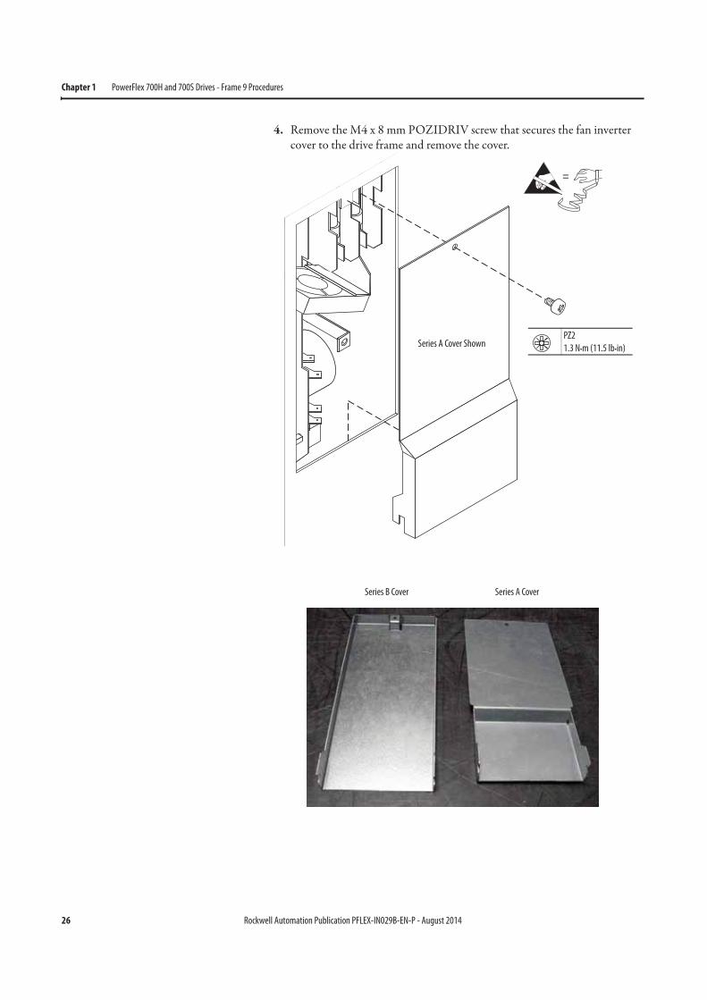
4. Remove the M4 x 8 mm POZIDRIV screw that secures the fan inverter cover to the drive frame and remove the cover.
12
34 ON
X6X1
X4
X5
X7
S1
X2
X8
=
PZ2
1.3 N•m (11.5 lb•in)Series A Cover Shown
Series B Cover Series A Cover
Rockwell Automation Publication PFLEX-IN029B-EN-P - August 2014 27
PowerFlex 700H and 700S Drives - Frame 9 Procedures Chapter 1
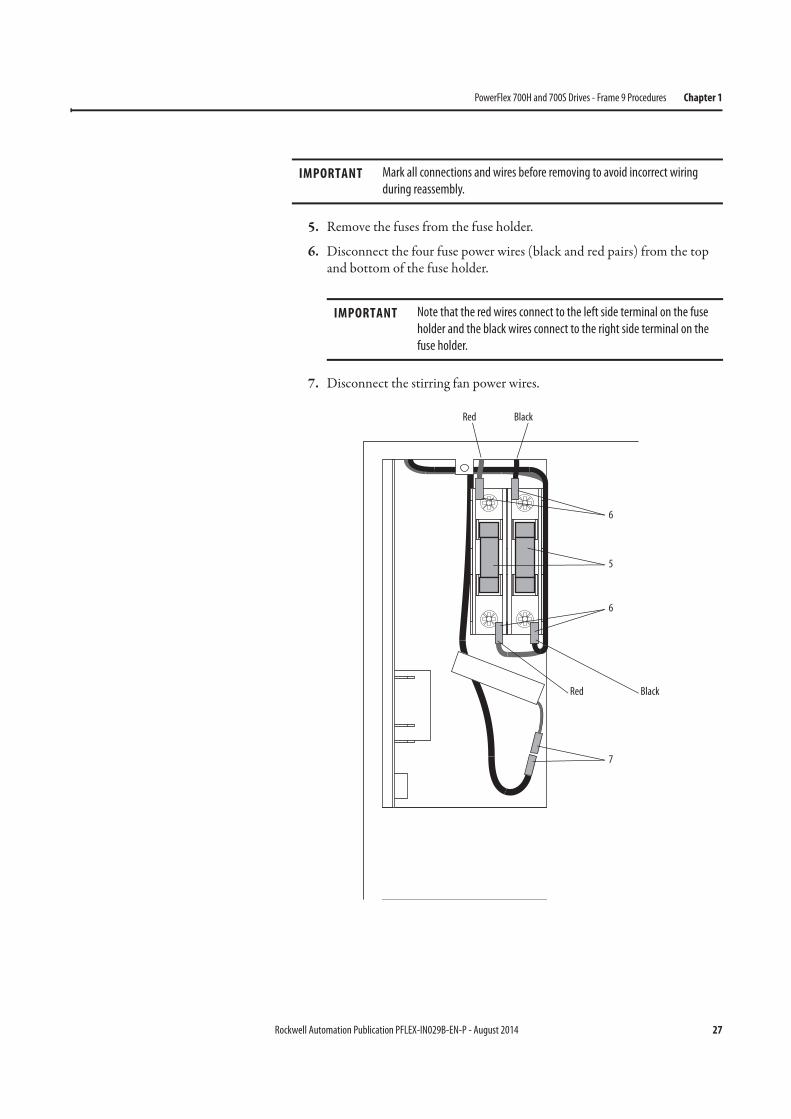
5. Remove the fuses from the fuse holder.
6. Disconnect the four fuse power wires (black and red pairs) from the top and bottom of the fuse holder.
7. Disconnect the stirring fan power wires.
IMPORTANT Mark all connections and wires before removing to avoid incorrect wiring
during reassembly.
IMPORTANT Note that the red wires connect to the left side terminal on the fuse
holder and the black wires connect to the right side terminal on the
fuse holder.
6
6
5
7
Red Black
Red Black
28 Rockwell Automation Publication PFLEX-IN029B-EN-P - August 2014
Chapter 1 PowerFlex 700H and 700S Drives - Frame 9 Procedures
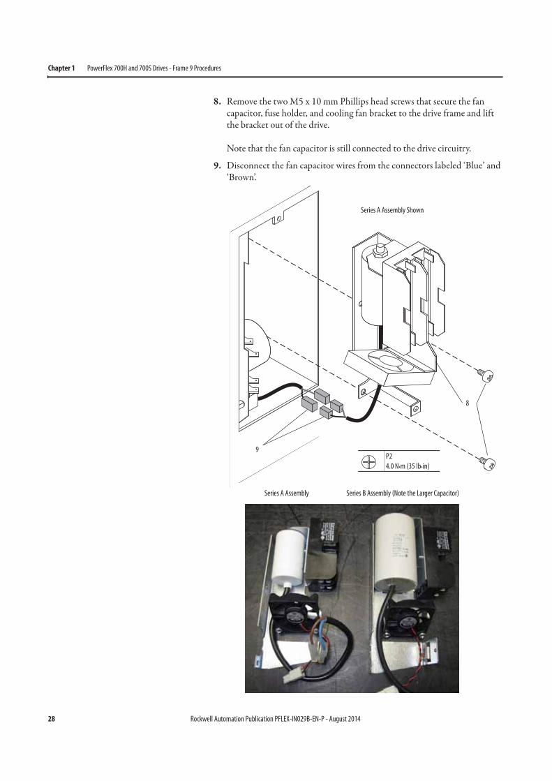
8. Remove the two M5 x 10 mm Phillips head screws that secure the fan capacitor, fuse holder, and cooling fan bracket to the drive frame and lift the bracket out of the drive.
Note that the fan capacitor is still connected to the drive circuitry.
9. Disconnect the fan capacitor wires from the connectors labeled ‘Blue’ and ‘Brown’.
12
34 ON
X6X1
X4
X5
X7
S1
X2
X8
9
8
P2
4.0 N•m (35 lb•in)
Series A Assembly Shown
Series A Assembly Series B Assembly (Note the Larger Capacitor)
Rockwell Automation Publication PFLEX-IN029B-EN-P - August 2014 29
PowerFlex 700H and 700S Drives - Frame 9 Procedures Chapter 1
Main Fan Fuses (20-PP20202) and Fuse Holder (20-PP20300) Removal
and Installation
The main fan fuses and fuse holder are located on the fan inverter capacitor bracket below the fan inverter cover.
1. Review the General Precautions on page 17.
2. Remove power from the drive. See Remove Power from the Drive on page 23.
3. Remove the lower protective cover from the drive. See Remove the Lower Protective Cover on page 24.
4. Remove the main fan inverter capacitor bracket. See Removing the Main Fan Inverter Capacitor Bracket on page 25.
5. Remove and replace the fuses, if necessary. See Checking the Fan Inverter Fuses on page 263.
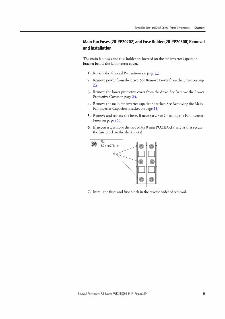
6. If, necessary, remove the two M4 x 8 mm POZIDRIV screws that secure the fuse block to the sheet metal.
7. Install the fuses and fuse block in the reverse order of removal.
PZ2
3.0 N•m (27 lb•in)
6

30 Rockwell Automation Publication PFLEX-IN029B-EN-P - August 2014
Chapter 1 PowerFlex 700H and 700S Drives - Frame 9 Procedures
Main Fan Inverter Cooling Fan (20-PP01049) Removal and
Installation
Note: This spare part kit includes a fan mounted on a piece of sheet metal. Remove the fan from the sheet metal and discard the sheet metal.
Follow these steps to remove and replace the main fan inverter cooling fan.
1. Review the General Precautions on page 17.
2. Remove power from the drive. See Remove Power from the Drive on page 23.
3. Remove the lower protective cover from the drive. See Remove the Lower Protective Cover on page 24.
4. Remove the main fan inverter capacitor bracket. See Removing the Main Fan Inverter Capacitor Bracket on page 25.
5. Remove the two M4 x 16 mm POZIDRIV screws that secure the cooling fan to the bracket and remove and discard the fan.
6. Install the new cooling fan in the reverse order of removal.
IMPORTANT Note the orientation of the air flow direction arrow on the cooling fan housing
before removal. The fan must be installed facing the same direction when re-
installed.
5. Note Direction of AirFlow Arrow on Fan.
PZ2
3.0 N•m (27 lb•in)
Rockwell Automation Publication PFLEX-IN029B-EN-P - August 2014 31
PowerFlex 700H and 700S Drives - Frame 9 Procedures Chapter 1
Main AC Fan Inverter Capacitor (SK-H1-FANCAP-F9) Removal and
Installation
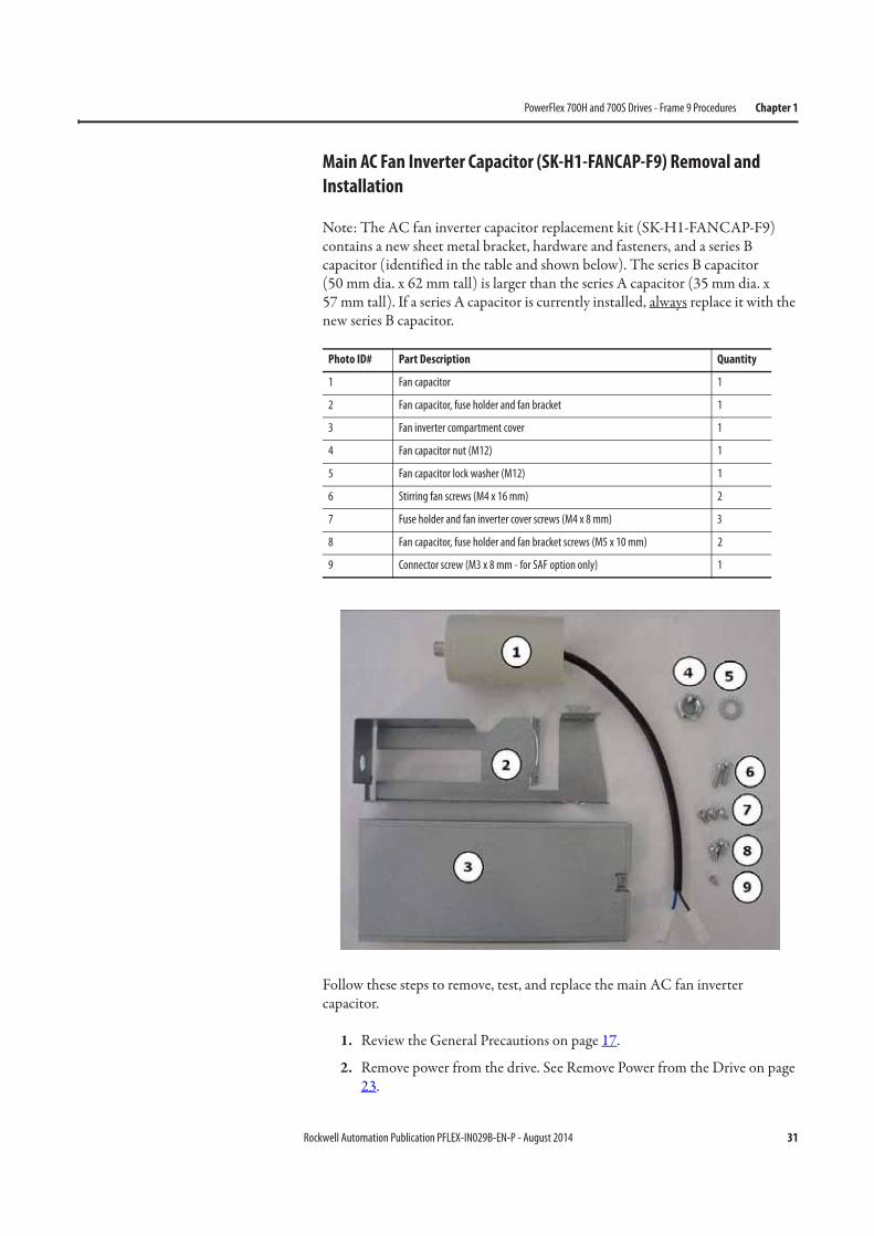
Note: The AC fan inverter capacitor replacement kit (SK-H1-FANCAP-F9) contains a new sheet metal bracket, hardware and fasteners, and a series B capacitor (identified in the table and shown below). The series B capacitor(50 mm dia. x 62 mm tall) is larger than the series A capacitor (35 mm dia. x57 mm tall). If a series A capacitor is currently installed, always replace it with the new series B capacitor.
Follow these steps to remove, test, and replace the main AC fan inverter capacitor.
1. Review the General Precautions on page 17.
2. Remove power from the drive. See Remove Power from the Drive on page 23.
Photo ID# Part Description Quantity
1 Fan capacitor 1
2 Fan capacitor, fuse holder and fan bracket 1
3 Fan inverter compartment cover 1
4 Fan capacitor nut (M12) 1
5 Fan capacitor lock washer (M12) 1
6 Stirring fan screws (M4 x 16 mm) 2
7 Fuse holder and fan inverter cover screws (M4 x 8 mm) 3
8 Fan capacitor, fuse holder and fan bracket screws (M5 x 10 mm) 2
9 Connector screw (M3 x 8 mm - for SAF option only) 1
32 Rockwell Automation Publication PFLEX-IN029B-EN-P - August 2014
Chapter 1 PowerFlex 700H and 700S Drives - Frame 9 Procedures
3. Remove the lower protective cover from the drive. See Remove the Lower Protective Cover on page 24.
4. Remove the main AC fan inverter capacitor bracket. See Remove the Removing the Main Fan Inverter Capacitor Bracket on page 25.
5. Remove the main AC fan inverter cooling fan from the bracket. Save the fan for reuse. See Main Fan Inverter Cooling Fan (20-PP01049) Removal and Installation on page 30.
6. Remove the two M4 x 8 mm POZIRDRIV screws that secure the fuse holder to the bracket and remove the fuse holder. Save the fuse holder for reuse.
7. If a series A capacitor is installed, continue with the next step. If a series B capacitor is installed, measure the value of the capacitor. If the value of the capacitor is less than 7 μF, continue with the next step.
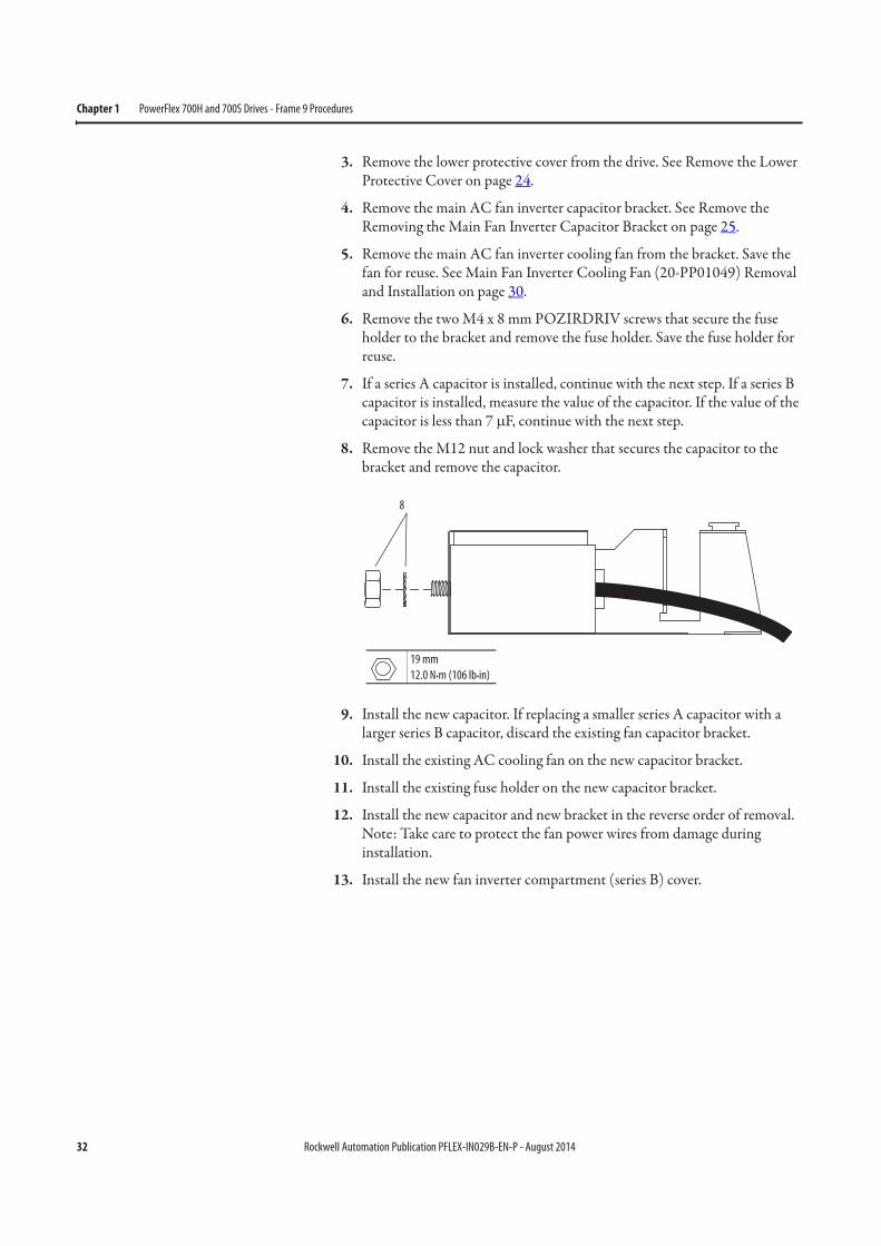
8. Remove the M12 nut and lock washer that secures the capacitor to the bracket and remove the capacitor.
9. Install the new capacitor. If replacing a smaller series A capacitor with a larger series B capacitor, discard the existing fan capacitor bracket.
10. Install the existing AC cooling fan on the new capacitor bracket.
11. Install the existing fuse holder on the new capacitor bracket.
12. Install the new capacitor and new bracket in the reverse order of removal. Note: Take care to protect the fan power wires from damage during installation.
13. Install the new fan inverter compartment (series B) cover.
8
19 mm
12.0 N•m (106 lb•in)
Rockwell Automation Publication PFLEX-IN029B-EN-P - August 2014 33
PowerFlex 700H and 700S Drives - Frame 9 Procedures Chapter 1
Main AC Fan Inverter Circuit Board Assembly (20-VB00299) Removal
and Installation
See Checking the Main AC Fan Inverter Circuit Board Diagnostic LEDs on page 268 for test procedures used to determine if the circuit board requires replacement.
Follow these steps to replace the main AC fan inverter circuit board.
1. Review the General Precautions on page 17.
2. Remove power from the drive. See Remove Power from the Drive on page 23.
3. Remove the lower protective cover from the drive. See Remove the Lower Protective Cover on page 24.
4. Remove the main AC fan inverter capacitor bracket. See Removing the Main Fan Inverter Capacitor Bracket on page 25.
5. Reach into the fan inverter compartment and disconnect the isolation transformer wires from X4 and X5 on the fan inverter board.
6. Disconnect the wires from connector X8 on the fan inverter board.
7. Disconnect the wires from connector X2 on the fan inverter board. Retain these wires for reuse.
IMPORTANT Mark the existing isolation transformer wires so that you can identify
them later in this procedure.
34 Rockwell Automation Publication PFLEX-IN029B-EN-P - August 2014
Chapter 1 PowerFlex 700H and 700S Drives - Frame 9 Procedures
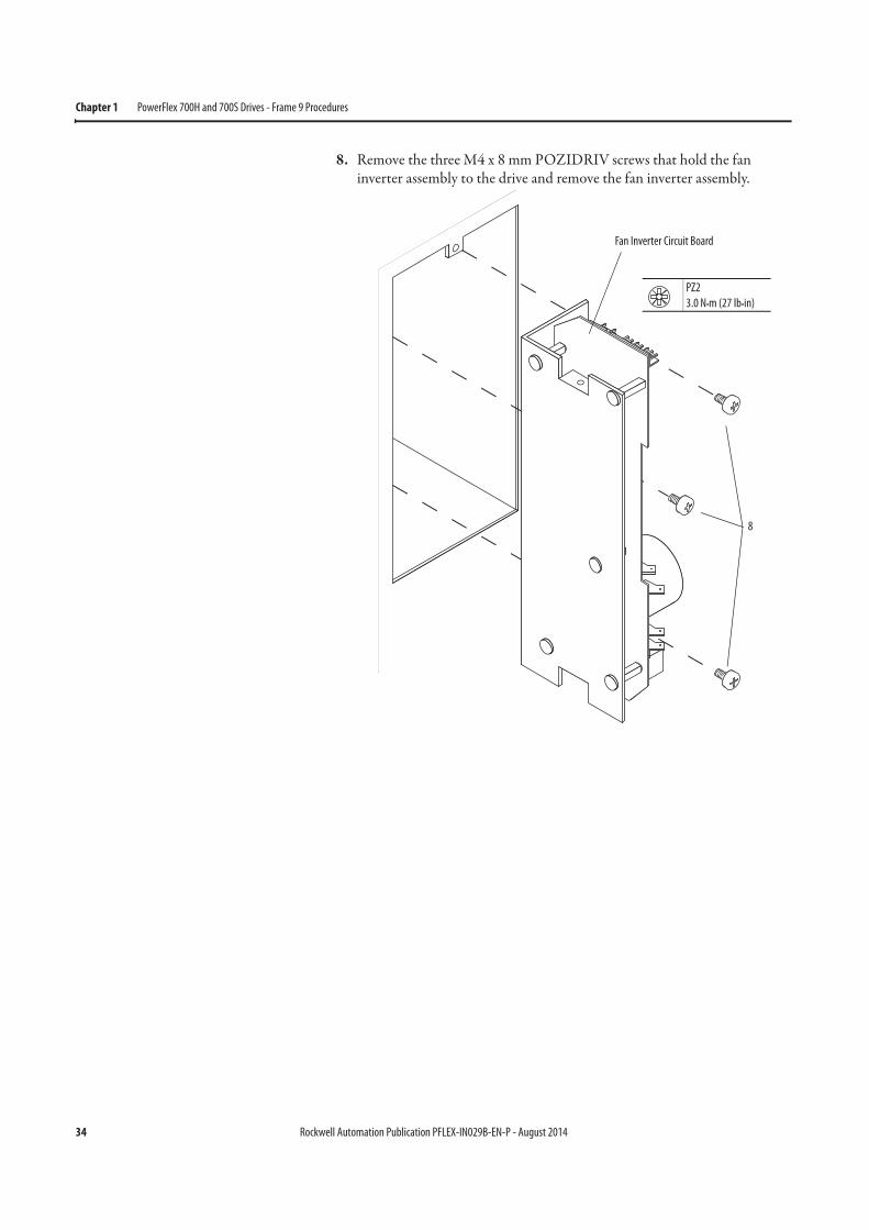
8. Remove the three M4 x 8 mm POZIDRIV screws that hold the fan inverter assembly to the drive and remove the fan inverter assembly.
12
34 ON
X6X1
X4
X5
X7
S1
X2
X8
Fan Inverter Circuit Board
PZ2
3.0 N•m (27 lb•in)
8

Rockwell Automation Publication PFLEX-IN029B-EN-P - August 2014 35
PowerFlex 700H and 700S Drives - Frame 9 Procedures Chapter 1
9. Install the new fan inverter assembly in the reverse order of removal.
IMPORTANT If you are servicing a 400V/480V Frame 9 drive, insert the jumper on connector
X3 as shown here.
Connect Jumper to Connector X3
X8
X2
IMPORTANT Verify that dip switch S1 on the new fan iverter board is properly configured, as
shown below.
X6X1
X4
X5
X7
S1
X2
X8
1
ON
23
4
S11
ON
23
4
S1-1 S1-2 S1-3 S1-4
Off Off On Off
Switch Setting To Indicate the Following:
S1 Off 50 Hz Fan Motor Frequency
S2 Off 220 V AC Motor Voltage
S3 On 230 V AC Motor Voltage
S4 Off Frame Size 9…14

36 Rockwell Automation Publication PFLEX-IN029B-EN-P - August 2014
Chapter 1 PowerFlex 700H and 700S Drives - Frame 9 Procedures
Main DC Fan Power Supply Circuit Board (SK-H1-DCFANBD1) Removal
and Installation
Note: You can retrofit an existing AC fan system or replace a DC fan system with a new DC fan system. See Energy-related Products Fan Efficiency Directive on page 12 for guidelines on replacing an existing fan system with a new DC fan system.
Follow these steps to remove and replace a DC fan system.
1. Review the General Precautions on page 17.
2. Remove power from the drive. See Remove Power from the Drive on page 23.
3. Remove the lower protective cover from the drive. See Remove the Lower Protective Cover on page 24.
4. Remove the M4 x 8 mm POZIDRIV screw that secures the fan power supply cover to the drive frame and remove the cover.
12
34 ON
X6X1
X4
X5
X7
S1
X2
X8 =
PZ2
1.3 N•m (11.5 lb•in)
Series A Cover Shown
Series B Cover Series A Cover
Rockwell Automation Publication PFLEX-IN029B-EN-P - August 2014 37
PowerFlex 700H and 700S Drives - Frame 9 Procedures Chapter 1
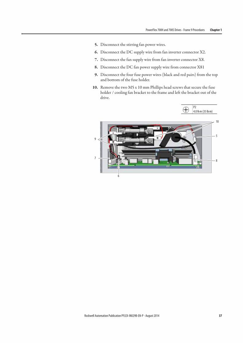
5. Disconnect the stirring fan power wires.
6. Disconnect the DC supply wire from fan inverter connector X2.
7. Disconnect the fan supply wire from fan inverter connector X8.
8. Disconnect the DC fan power supply wire from connector X81
9. Disconnect the four fuse power wires (black and red pairs) from the top and bottom of the fuse holder.
10. Remove the two M5 x 10 mm Phillips head screws that secure the fuse holder / cooling fan bracket to the frame and left the bracket out of the drive.
5
6
7
9
8
10
P2
4.0 N•m (35 lb•in)
38 Rockwell Automation Publication PFLEX-IN029B-EN-P - August 2014
Chapter 1 PowerFlex 700H and 700S Drives - Frame 9 Procedures
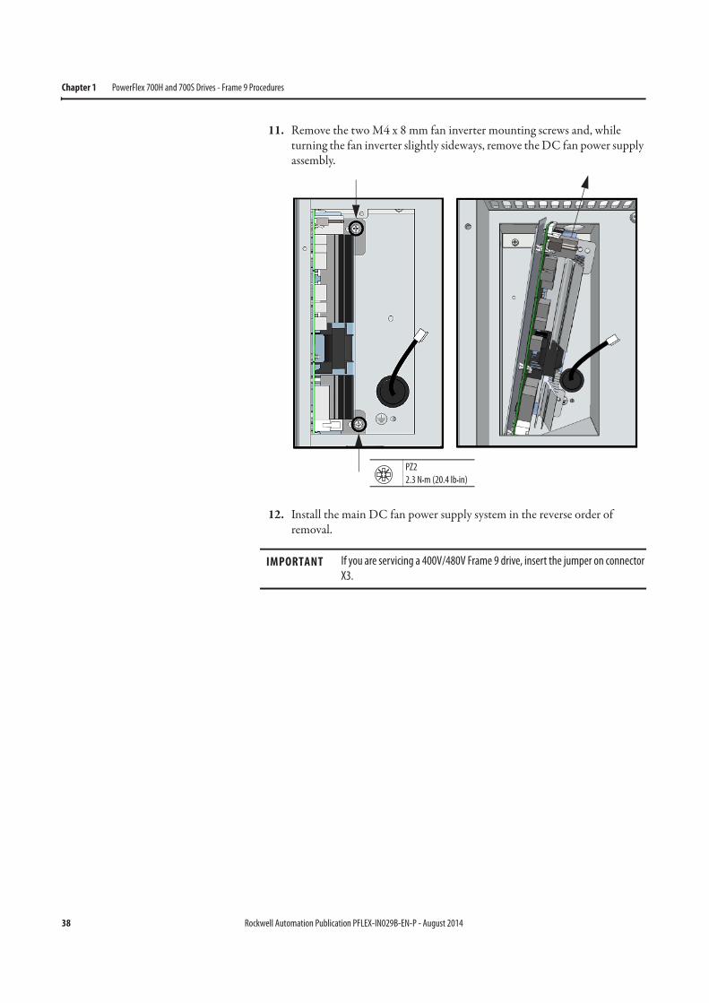
11. Remove the two M4 x 8 mm fan inverter mounting screws and, while turning the fan inverter slightly sideways, remove the DC fan power supply assembly.
12. Install the main DC fan power supply system in the reverse order of removal.
IMPORTANT If you are servicing a 400V/480V Frame 9 drive, insert the jumper on connector
X3.
PZ2
2.3 N•m (20.4 lb•in)
Rockwell Automation Publication PFLEX-IN029B-EN-P - August 2014 39
PowerFlex 700H and 700S Drives - Frame 9 Procedures Chapter 1
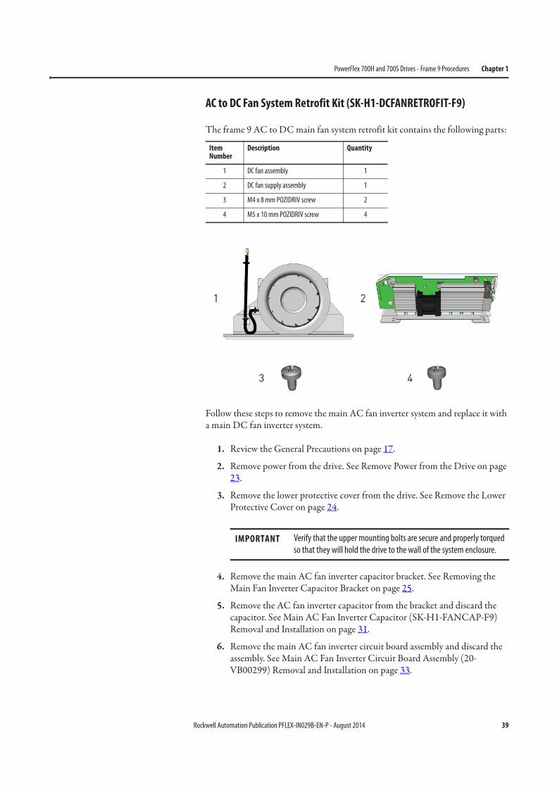
AC to DC Fan System Retrofit Kit (SK-H1-DCFANRETROFIT-F9)
The frame 9 AC to DC main fan system retrofit kit contains the following parts:
Follow these steps to remove the main AC fan inverter system and replace it with a main DC fan inverter system.
1. Review the General Precautions on page 17.
2. Remove power from the drive. See Remove Power from the Drive on page 23.
3. Remove the lower protective cover from the drive. See Remove the Lower Protective Cover on page 24.
4. Remove the main AC fan inverter capacitor bracket. See Removing the Main Fan Inverter Capacitor Bracket on page 25.
5. Remove the AC fan inverter capacitor from the bracket and discard the capacitor. See Main AC Fan Inverter Capacitor (SK-H1-FANCAP-F9) Removal and Installation on page 31.
6. Remove the main AC fan inverter circuit board assembly and discard the assembly. See Main AC Fan Inverter Circuit Board Assembly (20-VB00299) Removal and Installation on page 33.
Item Number
Description Quantity
1 DC fan assembly 1
2 DC fan supply assembly 1
3 M4 x 8 mm POZIDRIV screw 2
4 M5 x 10 mm POZIDRIV screw 4
IMPORTANT Verify that the upper mounting bolts are secure and properly torqued
so that they will hold the drive to the wall of the system enclosure.
40 Rockwell Automation Publication PFLEX-IN029B-EN-P - August 2014
Chapter 1 PowerFlex 700H and 700S Drives - Frame 9 Procedures
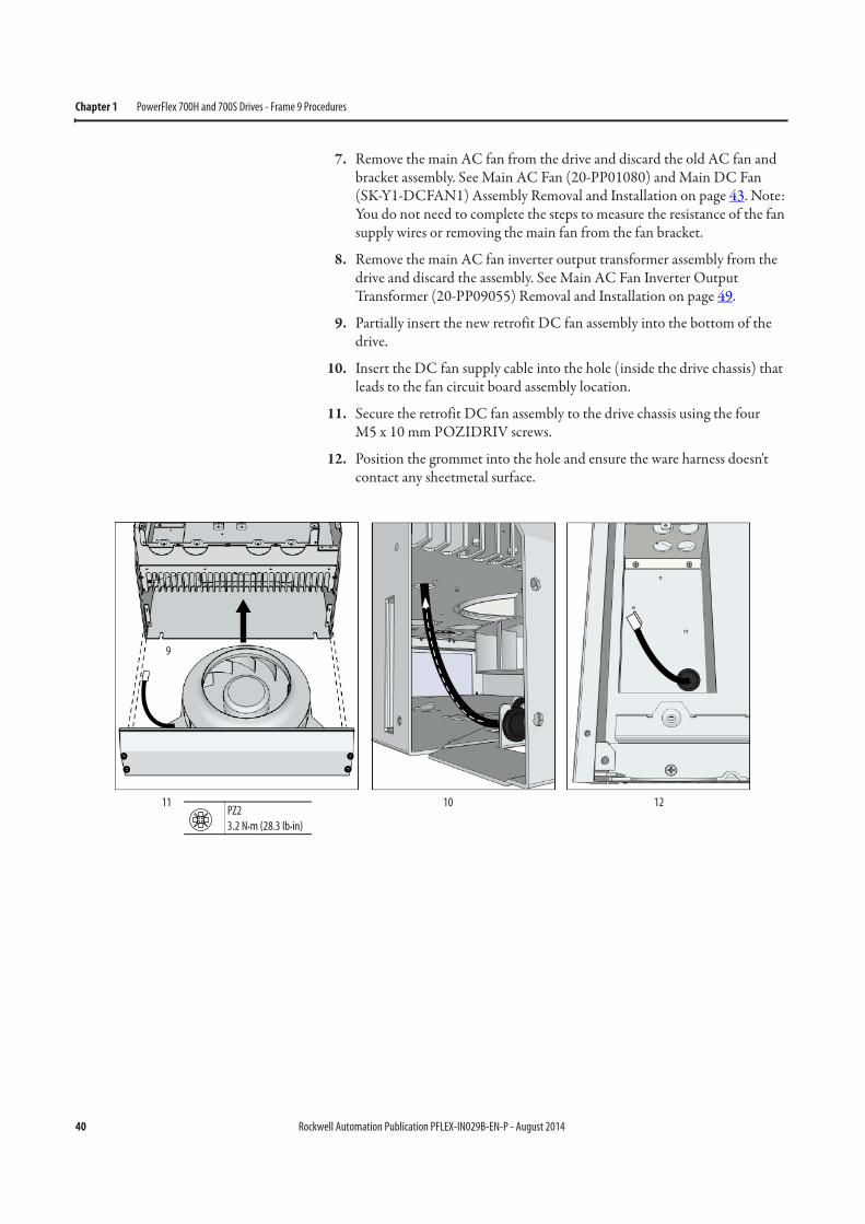
7. Remove the main AC fan from the drive and discard the old AC fan and bracket assembly. See Main AC Fan (20-PP01080) and Main DC Fan (SK-Y1-DCFAN1) Assembly Removal and Installation on page 43. Note: You do not need to complete the steps to measure the resistance of the fan supply wires or removing the main fan from the fan bracket.
8. Remove the main AC fan inverter output transformer assembly from the drive and discard the assembly. See Main AC Fan Inverter Output Transformer (20-PP09055) Removal and Installation on page 49.
9. Partially insert the new retrofit DC fan assembly into the bottom of the drive.
10. Insert the DC fan supply cable into the hole (inside the drive chassis) that leads to the fan circuit board assembly location.
11. Secure the retrofit DC fan assembly to the drive chassis using the four M5 x 10 mm POZIDRIV screws.
12. Position the grommet into the hole and ensure the ware harness doesn't contact any sheetmetal surface.
PZ2
3.2 N•m (28.3 lb•in)
9
10 1211
Rockwell Automation Publication PFLEX-IN029B-EN-P - August 2014 41
PowerFlex 700H and 700S Drives - Frame 9 Procedures Chapter 1
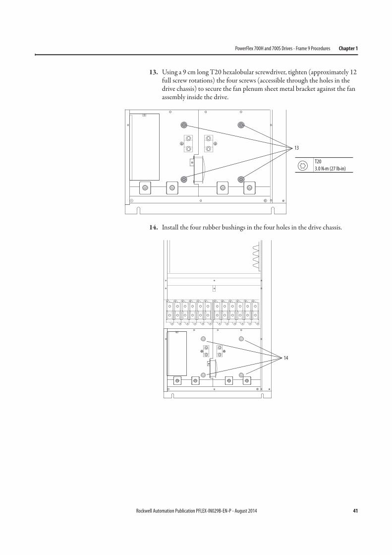
13. Using a 9 cm long T20 hexalobular screwdriver, tighten (approximately 12 full screw rotations) the four screws (accessible through the holes in the drive chassis) to secure the fan plenum sheet metal bracket against the fan assembly inside the drive.
14. Install the four rubber bushings in the four holes in the drive chassis.
13
T20
3.0 N•m (27 lb•in)
14
42 Rockwell Automation Publication PFLEX-IN029B-EN-P - August 2014
Chapter 1 PowerFlex 700H and 700S Drives - Frame 9 Procedures
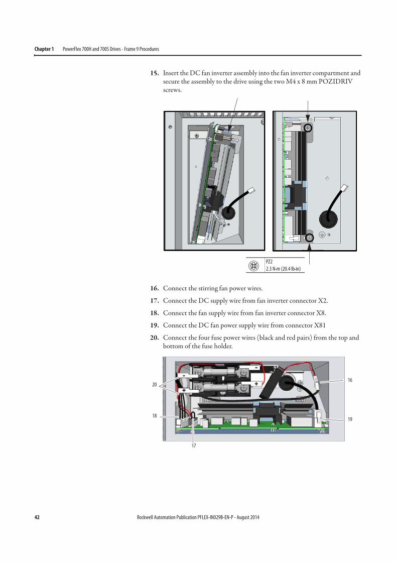
15. Insert the DC fan inverter assembly into the fan inverter compartment and secure the assembly to the drive using the two M4 x 8 mm POZIDRIV screws.
16. Connect the stirring fan power wires.
17. Connect the DC supply wire from fan inverter connector X2.
18. Connect the fan supply wire from fan inverter connector X8.
19. Connect the DC fan power supply wire from connector X81
20. Connect the four fuse power wires (black and red pairs) from the top and bottom of the fuse holder.
PZ2
2.3 N•m (20.4 lb•in)
16
17
18
20
19

Rockwell Automation Publication PFLEX-IN029B-EN-P - August 2014 43
PowerFlex 700H and 700S Drives - Frame 9 Procedures Chapter 1
21. Secure the fan inverter cover to the drive using the M4 x 8 mm POZIDRIV screw.
22. Install the lower protective cover in the reverse order of removal. See Remove the Lower Protective Cover on page 24.
23. Remove the backing from the drive modification label and attach the label, in a clearly visible location, to the front of the drive.
24. Write “DC fan retrofit” and the installation date on the label.
Main AC Fan (20-PP01080) and Main DC Fan (SK-Y1-DCFAN1) Assembly
Removal and Installation
Follow these steps to measure the resistance between the main fan supply wires and remove and replace the main fan, if necessary.
Notes:• To identify which fan is installed in your drive, see Fan Inverter System
Block Diagrams on page 257.• For AC fan systems, the sheet metal bracket is available as a spare part (SK-
H1-FR9BRKT). See page 288 for details. For DC fan systems, the sheet metal bracket is only available as part of the retrofit kit (SK-H1-DCFANRETROFIT-F9). See page 289 for details.
• The main fan replacement kit only contains the fan motor and impeller assembly. Therefore, if the sheet metal mounting bracket is not available as a spare part for your fan system, it must be reused.
12
34 ON
X6X1
X4
X5
X7
S1
X2
X8
PZ2
1.3 N•m (11.5 lb•in)
Series A Cover Shown
44 Rockwell Automation Publication PFLEX-IN029B-EN-P - August 2014
Chapter 1 PowerFlex 700H and 700S Drives - Frame 9 Procedures
1. Review the General Precautions on page 17.
2. Remove power from the drive. See Remove Power from the Drive on page 23.
3. Remove the lower protective cover from the drive. See Remove the Lower Protective Cover on page 24.
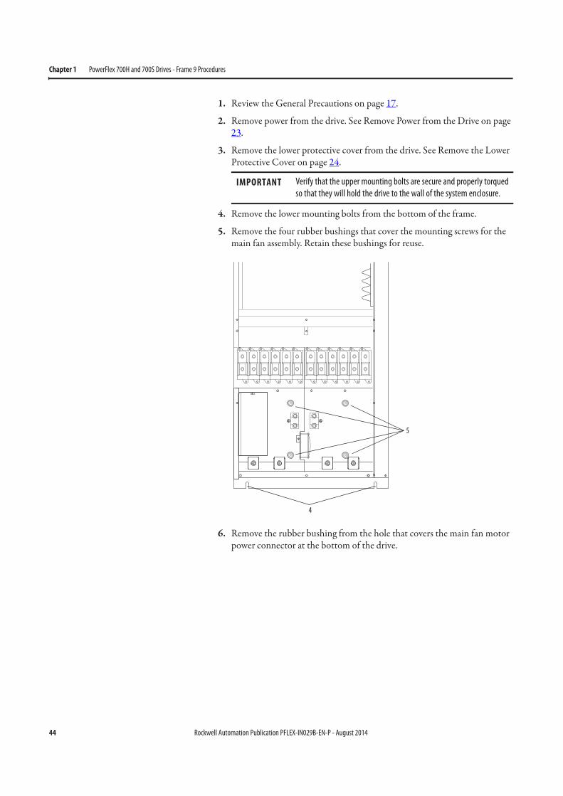
4. Remove the lower mounting bolts from the bottom of the frame.
5. Remove the four rubber bushings that cover the mounting screws for the main fan assembly. Retain these bushings for reuse.
6. Remove the rubber bushing from the hole that covers the main fan motor power connector at the bottom of the drive.
IMPORTANT Verify that the upper mounting bolts are secure and properly torqued
so that they will hold the drive to the wall of the system enclosure.
5
4
Rockwell Automation Publication PFLEX-IN029B-EN-P - August 2014 45
PowerFlex 700H and 700S Drives - Frame 9 Procedures Chapter 1
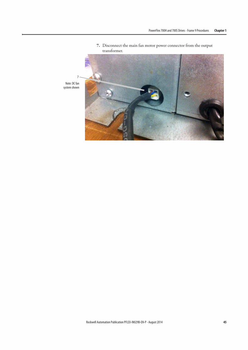
7. Disconnect the main fan motor power connector from the output transformer.
7
Note: DC fansystem shown
46 Rockwell Automation Publication PFLEX-IN029B-EN-P - August 2014
Chapter 1 PowerFlex 700H and 700S Drives - Frame 9 Procedures
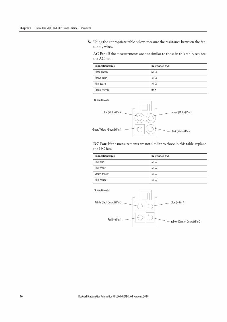
8. Using the appropriate table below, measure the resistance between the fan supply wires.
AC Fan: If the measurements are not similar to those in this table, replace the AC fan.
DC Fan: If the measurements are not similar to those in this table, replace the DC fan.
Connection wires Resistance ±5%
Black-Brown 62 Ω
Brown-Blue 36 Ω
Blue-Black 27 Ω
Green-chassis 0 Ω
Connection wires Resistance ±5%
Red-Blue ∞ Ω
Red-White ∞ Ω
White-Yellow ∞ Ω
Blue-White ∞ Ω
Blue (Motor) Pin 4
Green/Yellow (Ground) Pin 1
Brown (Motor) Pin 3
Black (Motor) Pin 2
AC Fan Pinouts
White (Tach Output) Pin 3
Red (+) Pin 1
Blue (-) Pin 4
Yellow (Control Output) Pin 2
DC Fan Pinouts
Rockwell Automation Publication PFLEX-IN029B-EN-P - August 2014 47
PowerFlex 700H and 700S Drives - Frame 9 Procedures Chapter 1
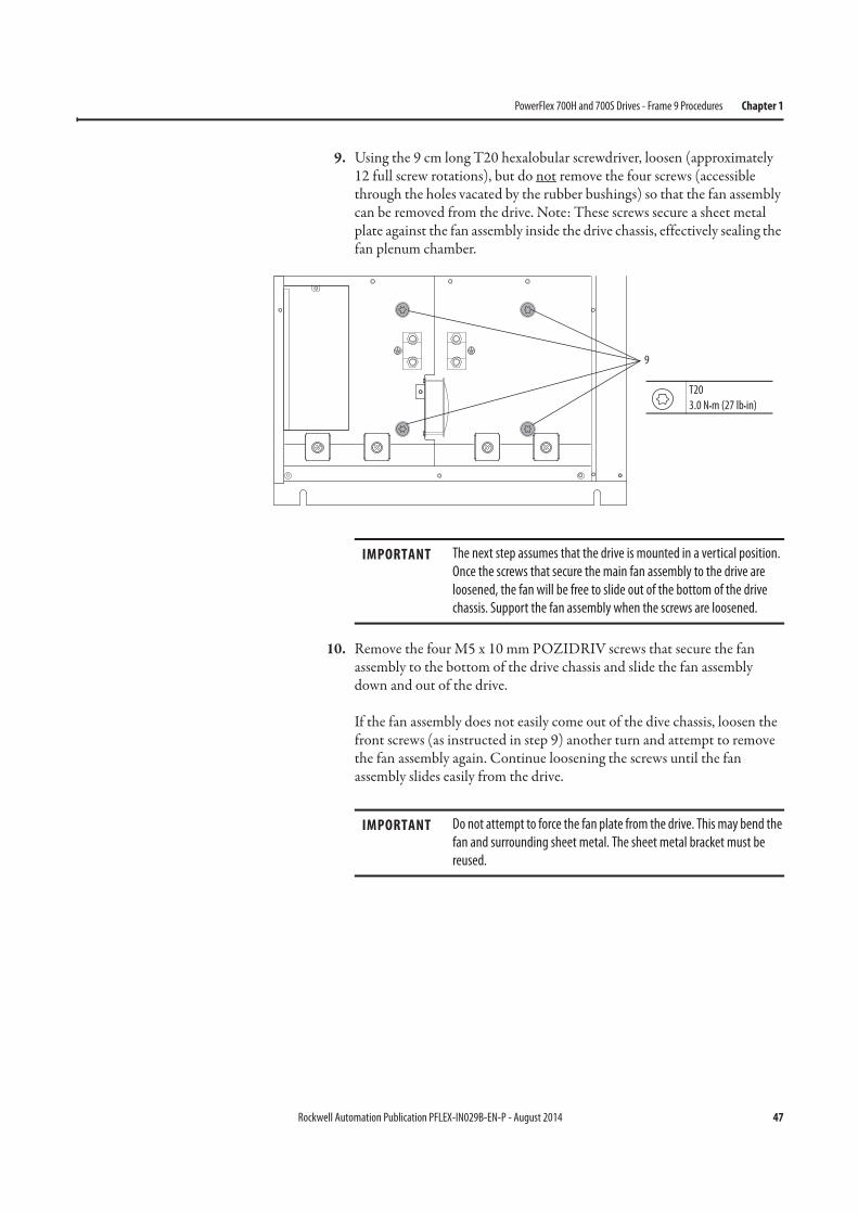
9. Using the 9 cm long T20 hexalobular screwdriver, loosen (approximately 12 full screw rotations), but do not remove the four screws (accessible through the holes vacated by the rubber bushings) so that the fan assembly can be removed from the drive. Note: These screws secure a sheet metal plate against the fan assembly inside the drive chassis, effectively sealing the fan plenum chamber.
10. Remove the four M5 x 10 mm POZIDRIV screws that secure the fan assembly to the bottom of the drive chassis and slide the fan assembly down and out of the drive.
If the fan assembly does not easily come out of the dive chassis, loosen the front screws (as instructed in step 9) another turn and attempt to remove the fan assembly again. Continue loosening the screws until the fan assembly slides easily from the drive.
9
T20
3.0 N•m (27 lb•in)
IMPORTANT The next step assumes that the drive is mounted in a vertical position.
Once the screws that secure the main fan assembly to the drive are
loosened, the fan will be free to slide out of the bottom of the drive
chassis. Support the fan assembly when the screws are loosened.
IMPORTANT Do not attempt to force the fan plate from the drive. This may bend the
fan and surrounding sheet metal. The sheet metal bracket must be
reused.

48 Rockwell Automation Publication PFLEX-IN029B-EN-P - August 2014
Chapter 1 PowerFlex 700H and 700S Drives - Frame 9 Procedures
11. Remove the four screws that secure the main fan to the fan bracket and discard the fan. The sheet metal bracket must be reused.
Note: The Main AC and DC fans have different mounting hardware and hole dimensions. The AC fan uses four M4 x 8 mm screws that are spaced 40 mm apart on the bracket. The DC fan uses four M5 x 10 mm screws that are spaced 65 mm apart on the bracket. Based on the manufacturing date, the sheet metal mounting bracket was fabricated for either an AC fan, a DC fan, or both.
12. Install the main fan in the reverse order of removal.
IMPORTANT Verify that the fan turns easily on the bracket before installing it in the
drive.
10
PZ2
4.0 N•m (35 lb•in)
11
F - 6.4 mm (0.25 in.)
4.0 N•m (35 lb•in)
Rockwell Automation Publication PFLEX-IN029B-EN-P - August 2014 49
PowerFlex 700H and 700S Drives - Frame 9 Procedures Chapter 1
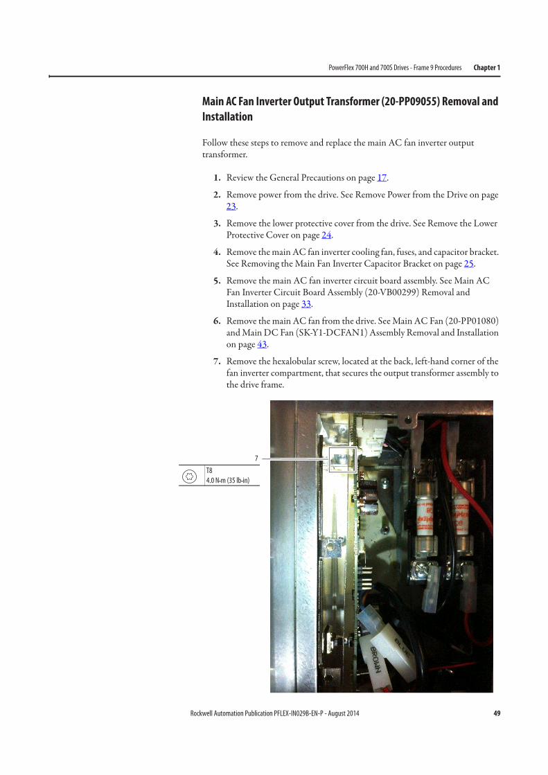
Main AC Fan Inverter Output Transformer (20-PP09055) Removal and
Installation
Follow these steps to remove and replace the main AC fan inverter output transformer.
1. Review the General Precautions on page 17.
2. Remove power from the drive. See Remove Power from the Drive on page 23.
3. Remove the lower protective cover from the drive. See Remove the Lower Protective Cover on page 24.
4. Remove the main AC fan inverter cooling fan, fuses, and capacitor bracket. See Removing the Main Fan Inverter Capacitor Bracket on page 25.
5. Remove the main AC fan inverter circuit board assembly. See Main AC Fan Inverter Circuit Board Assembly (20-VB00299) Removal and Installation on page 33.
6. Remove the main AC fan from the drive. See Main AC Fan (20-PP01080) and Main DC Fan (SK-Y1-DCFAN1) Assembly Removal and Installation on page 43.
7. Remove the hexalobular screw, located at the back, left-hand corner of the fan inverter compartment, that secures the output transformer assembly to the drive frame.
7
T8
4.0 N•m (35 lb•in)
50 Rockwell Automation Publication PFLEX-IN029B-EN-P - August 2014
Chapter 1 PowerFlex 700H and 700S Drives - Frame 9 Procedures
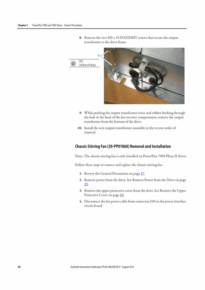
8. Remove the two M5 x 10 POZIDRIV screws that secure the output transformer to the drive frame.
9. While pushing the output transformer wires and rubber bushing through the hole in the back of the fan inverter compartment, remove the output transformer from the bottom of the drive.
10. Install the new output transformer assembly in the reverse order of removal.
Chassis Stirring Fan (20-PP01068) Removal and Installation
Note: The chassis stirring fan is only installed on PowerFlex 700S Phase II drives.
Follow these steps to remove and replace the chassis stirring fan.
1. Review the General Precautions on page 17.
2. Remove power from the drive. See Remove Power from the Drive on page 23.
3. Remove the upper protective cover from the drive. See Remove the Upper Protective Cover on page 24.
4. Disconnect the fan power cable from connector J18 on the power interface circuit board.
8
PZ2
4.0 N•m (35 lb•in)
Rockwell Automation Publication PFLEX-IN029B-EN-P - August 2014 51
PowerFlex 700H and 700S Drives - Frame 9 Procedures Chapter 1
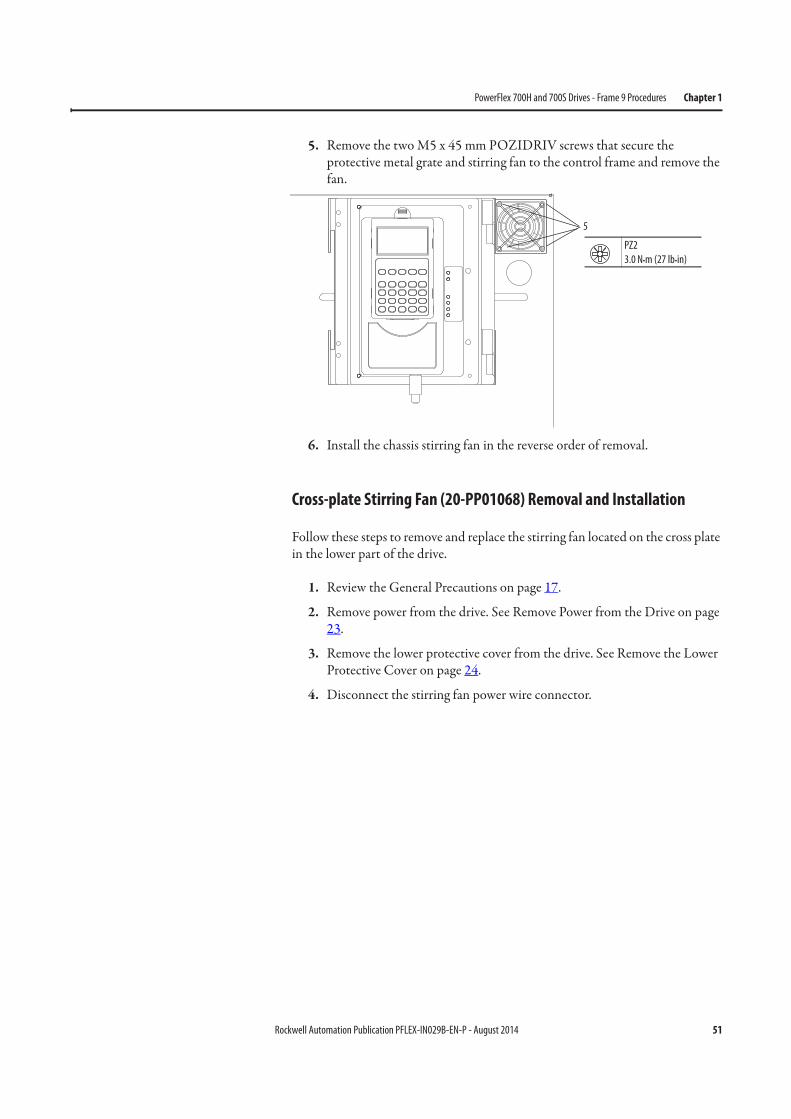
5. Remove the two M5 x 45 mm POZIDRIV screws that secure the protective metal grate and stirring fan to the control frame and remove the fan.
6. Install the chassis stirring fan in the reverse order of removal.
Cross-plate Stirring Fan (20-PP01068) Removal and Installation
Follow these steps to remove and replace the stirring fan located on the cross plate in the lower part of the drive.
1. Review the General Precautions on page 17.
2. Remove power from the drive. See Remove Power from the Drive on page 23.
3. Remove the lower protective cover from the drive. See Remove the Lower Protective Cover on page 24.
4. Disconnect the stirring fan power wire connector.
5
PZ2
3.0 N•m (27 lb•in)
52 Rockwell Automation Publication PFLEX-IN029B-EN-P - August 2014
Chapter 1 PowerFlex 700H and 700S Drives - Frame 9 Procedures
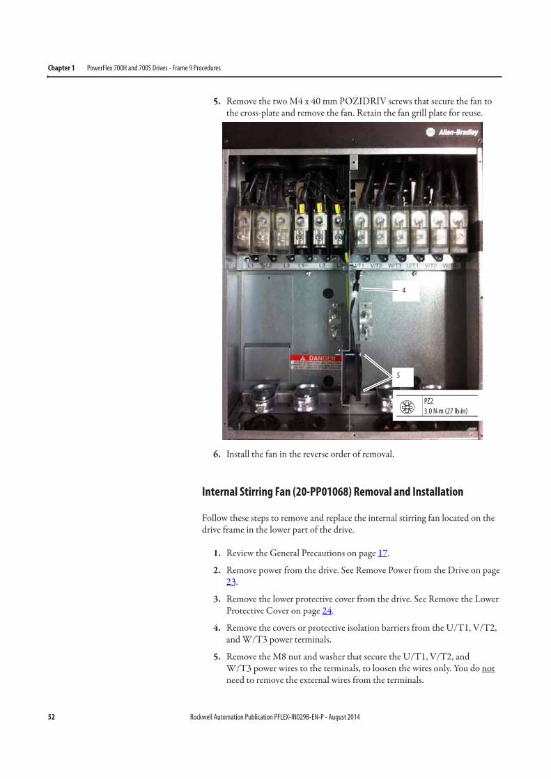
5. Remove the two M4 x 40 mm POZIDRIV screws that secure the fan to the cross-plate and remove the fan. Retain the fan grill plate for reuse.
6. Install the fan in the reverse order of removal.
Internal Stirring Fan (20-PP01068) Removal and Installation
Follow these steps to remove and replace the internal stirring fan located on the drive frame in the lower part of the drive.
1. Review the General Precautions on page 17.
2. Remove power from the drive. See Remove Power from the Drive on page 23.
3. Remove the lower protective cover from the drive. See Remove the Lower Protective Cover on page 24.
4. Remove the covers or protective isolation barriers from the U/T1, V/T2, and W/T3 power terminals.
5. Remove the M8 nut and washer that secure the U/T1, V/T2, andW/T3 power wires to the terminals, to loosen the wires only. You do not need to remove the external wires from the terminals.
4
5
PZ2
3.0 N•m (27 lb•in)
Rockwell Automation Publication PFLEX-IN029B-EN-P - August 2014 53
PowerFlex 700H and 700S Drives - Frame 9 Procedures Chapter 1
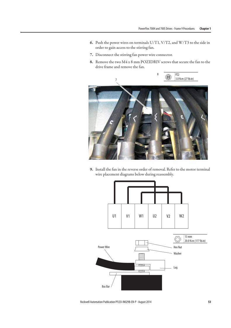
6. Push the power wires on terminals U/T1, V/T2, and W/T3 to the side in order to gain access to the stirring fan.
7. Disconnect the stirring fan power wire connector.
8. Remove the two M4 x 8 mm POZIDRIV screws that secure the fan to the drive frame and remove the fan.
9. Install the fan in the reverse order of removal. Refer to the motor terminal wire placement diagrams below during reassembly.
7
8 PZ2
3.0 N•m (27 lb•in)
Lug
Hex Nut
Washer
Bus Bar
Power Wire
U1 U2V1 V2W1 W2
13 mm
20.0 N•m (177 lb•in)

54 Rockwell Automation Publication PFLEX-IN029B-EN-P - August 2014
Chapter 1 PowerFlex 700H and 700S Drives - Frame 9 Procedures
Notes:
Rockwell Automation Publication PFLEX-IN029B-EN-P - August 2014 55
Chapter 2
PowerFlex 700H and 700S Drives - Frame 10 Procedures
This chapter contains spare part information and procedures for testing and replacing fan system components for frame 10 PowerFlex 700H and PowerFlex 700S drives. See Appendix A PowerFlex 700H and 700S Diagnostic Procedures on page 255 for additional component test procedures.
Topic Page
Frame 10 Fan System Spare Parts 56
Tools Needed for Frame 10 Fan System Repairs 56
Frame 10 Schematic Diagrams 57
Frame 10 Fan System Replacement Procedures 59
Remove Power from the Drive 59
Move the Control Frame and Remove the Air Flow Plate and Protective Covers 60
Remove the Main AC or DC Fan Power Supply Assemblies 63
Main AC Fan Inverter Circuit Board (20-VB00299) and AC Fan Output Transformer Assembly [20-FR10844 (Left) or 20-FR10845 (Right)] Removal and Installation
67
Main DC Fan Power Supply System (SK-H1-DCFANBD1) Removal and Installation 69
AC to DC Fan System Retrofit Kit (SK-H1-DCFANRETROFIT-F10) 70
Main AC Fan Inverter Capacitor (SK-H1-FANCAP-F1012) Removal and Installation 74
Main AC Fan (20-PP01080) and Main DC Fan (SK-Y1-DCFAN1) Assembly Removal and Installation
78
ASIC Circuit Board Assembly Cooling Fan (20-PP01096) Removal and Installation 82
AC or DC Fan System Fuses (20-PP20202) and Fuse Holder (20-PP20300) Removal and Installation
85

56 Rockwell Automation Publication PFLEX-IN029B-EN-P - August 2014
Chapter 2 PowerFlex 700H and 700S Drives - Frame 10 Procedures
Frame 10 Fan System Spare Parts
AC Fan Systems
See Available Fan System Kits starting on page 277 for an illustration of the spare part kit contents.
DC Fan Systems
See Available Fan System Kits starting on page 277 for an illustration of the spare part kit contents.
Tools Needed for Frame 10 Fan System Repairs
• #1 POZIDRIV screwdriver• #2 POZIDRIV screwdriver• 6 mm hex key• 19 mm socket wrench• T15, T20, T25, and T30 hexalobular screwdriver• Fuse puller• Nose pliers• Wire cutter• Optional: PowerFlex 700H and 700S maintenance stand (cat. No. 20-
MAINSTND)
Cat. No. Part Description Quantity per Drive
Original Vendor and Model Number
20-FR10844 Output transformer assembly for main AC fan inverter (left side)
1 –
20-FR10845 Output transformer assembly for main AC fan inverter (right side)
1 –
20-PP01080 230 W Main AC fan assembly 2 –
20-PP01096 60 mm internal fan for ASIC board 1 Sinwan
SD5012PT-24H (2)
(2) The part may not contain wires, connectors, or mounting hardware when bought directly from vendor.
20-PP20202 Fuse for fan system 2 Ferraz Shawmut
ATQ8 (3)
(3) The factory default fuses are Ferraz Shawmut ATQ8, 8 A fuses. Older drives may contain Bussman 6 A fuses.
20-PP20300 Fuse holder for main fan system fuses 1 Ferraz Shawmut
30322
20-VB00299 Main AC fan inverter circuit board (1)
(1) The same fan inverter circuit board is used for all drive voltage classes.
2 –
SK-H1-FANCAP-F1012 Capacitor (7 μF) for main AC fan inverter 2 –
Cat. No. Part Description Quantity per Drive
Original Vendor and Model Number
SK-Y1-DCFAN1 Main DC fan assembly 2 –
SK-H1-DCFANBD1 Main DC fan power supply circuit board (1)
(1) Circuit board only, no sheet metal bracket.
2 –
SK-H1-DCFANRETROFIT-F10 AC to DC fan system retrofit kit 1 –
Rockwell Automation Publication PFLEX-IN029B-EN-P - August 2014 57
PowerFlex 700H and 700S Drives - Frame 10 Procedures Chapter 2
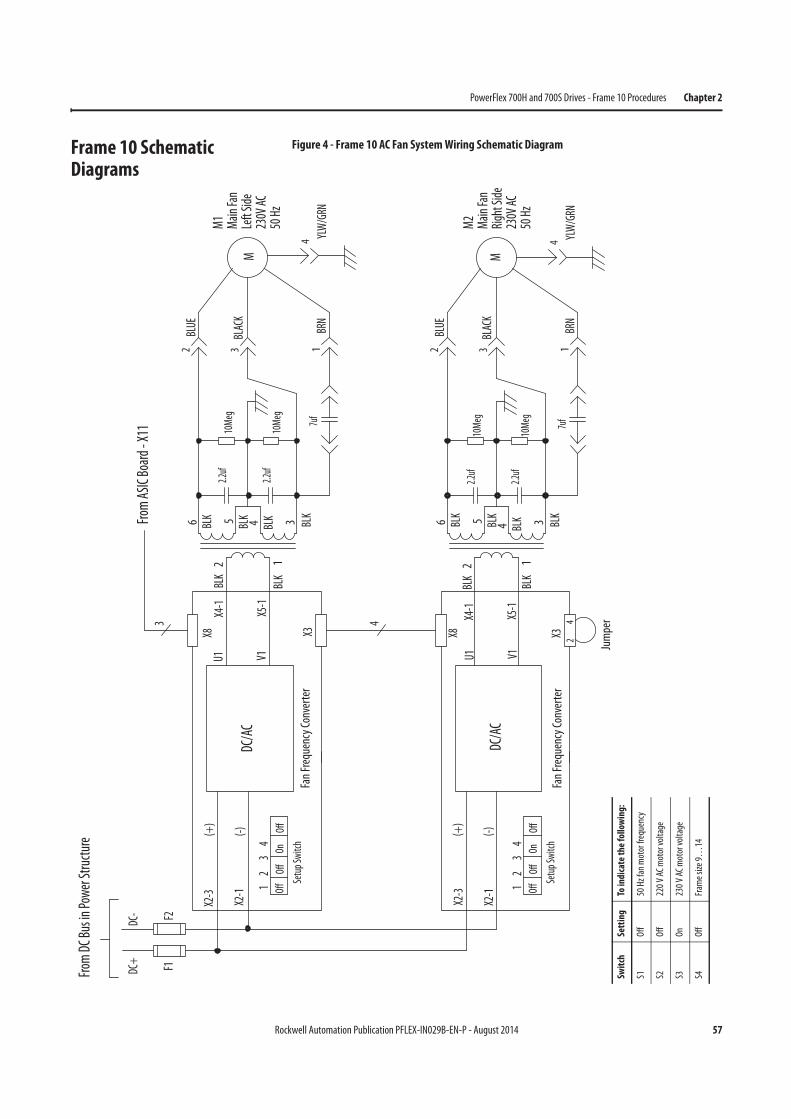
Frame 10 Schematic Diagrams
Figure 4 - Frame 10 AC Fan System Wiring Schematic Diagram
(+)
1 2
3
4
OffOn
DC/AC
X8
F1
Setup Switch
X3
From
ASIC Board - X11
U1 V1
X4-1
X5-1
(-)
X2-1
X2-3
X5-1
X4-1
X2-1
X2-3
V1
X3
(-)
(+)
X8
U1
3
DC-
DC+
4
Fan
Frequency Converter
DC/AC
BLK
1
BLK2
3 BLK
BLK
2.2uf
4BLK5
2.2uf
17uf
BRN
10Meg
10Meg
M1
Main
Fan
Left Side
230V
AC
50 Hz
6BLUE
2
BLK
BLK
1
BLK2
3 BLK
BLK
2.2uf
4BLK5
2.2uf
7uf
10Meg
10Meg
YLW/GRN
4
6
BLK
Jumper
24
F2
Fan
Frequency Converter
From
DC Bus in Power
Structure
M2
Main
Fan
Right Side
230V
AC
50 Hz
OffOff
1 2
3
4
OffOn
Setup Switch
OffOff
M
BLACK
3
YLW/GRN
4
M
1BRN
BLUE
2
BLACK
3
Swit
chSe
ttin
gTo
indi
cate
th
e fo
llow
ing:
S1O
ff50
Hz
fan
mot
or fr
eque
ncy
S2O
ff22
0 V
AC m
otor
vol
tage
S3O
n23
0 V
AC m
otor
vol
tage
S4O
ffFr
ame
size
9…
14
58 Rockwell Automation Publication PFLEX-IN029B-EN-P - August 2014
Chapter 2 PowerFlex 700H and 700S Drives - Frame 10 Procedures
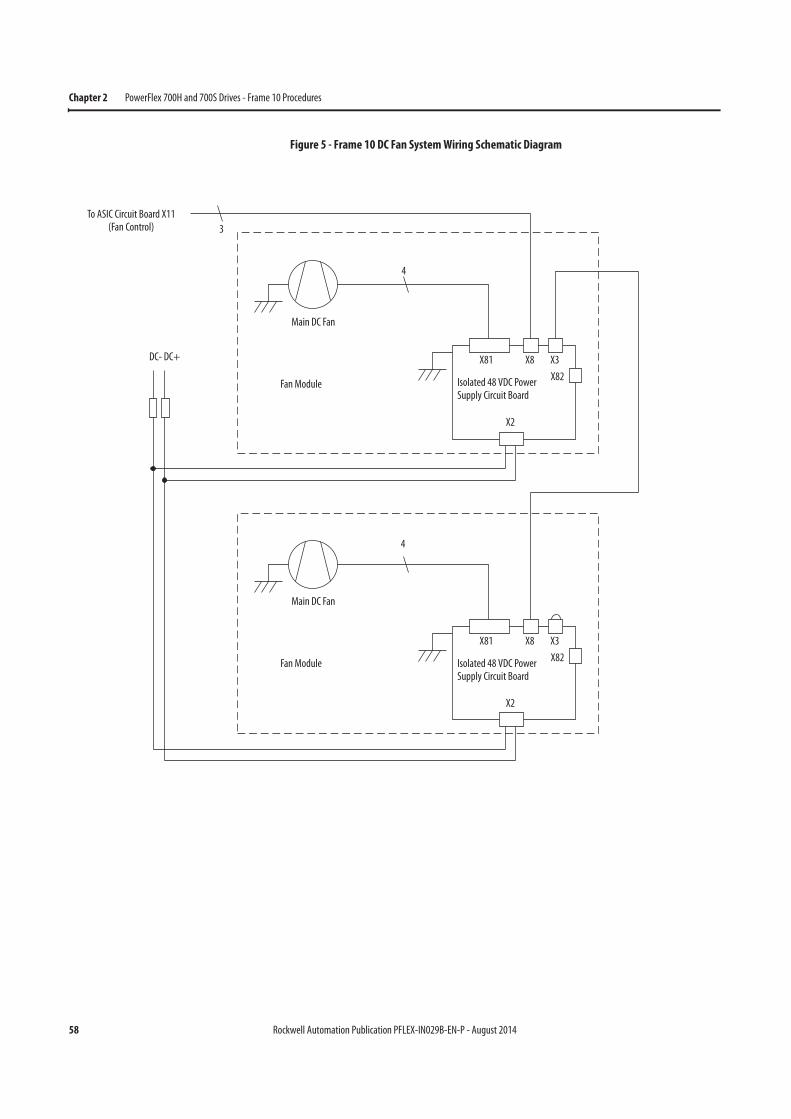
Figure 5 - Frame 10 DC Fan System Wiring Schematic Diagram
3
To ASIC Circuit Board X11(Fan Control)
4
Main DC Fan
Fan Module
DC- DC+
Isolated 48 VDC Power Supply Circuit Board
X81 X8 X3
X82
X2
Isolated 48 VDC Power Supply Circuit Board
X81 X8 X3
X82
X2
Main DC Fan
Fan Module
4
Rockwell Automation Publication PFLEX-IN029B-EN-P - August 2014 59
PowerFlex 700H and 700S Drives - Frame 10 Procedures Chapter 2
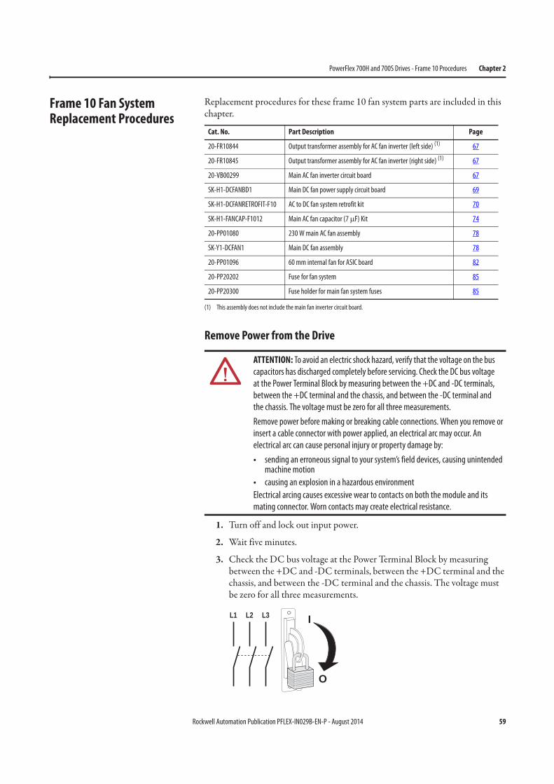
Frame 10 Fan System Replacement Procedures
Replacement procedures for these frame 10 fan system parts are included in this chapter.
Remove Power from the Drive
1. Turn off and lock out input power.
2. Wait five minutes.
3. Check the DC bus voltage at the Power Terminal Block by measuring between the +DC and -DC terminals, between the +DC terminal and the chassis, and between the -DC terminal and the chassis. The voltage must be zero for all three measurements.
Cat. No. Part Description Page
20-FR10844 Output transformer assembly for AC fan inverter (left side) (1)
(1) This assembly does not include the main fan inverter circuit board.
67
20-FR10845 Output transformer assembly for AC fan inverter (right side) (1) 67
20-VB00299 Main AC fan inverter circuit board 67
SK-H1-DCFANBD1 Main DC fan power supply circuit board 69
SK-H1-DCFANRETROFIT-F10 AC to DC fan system retrofit kit 70
SK-H1-FANCAP-F1012 Main AC fan capacitor (7 μF) Kit 74
20-PP01080 230 W main AC fan assembly 78
SK-Y1-DCFAN1 Main DC fan assembly 78
20-PP01096 60 mm internal fan for ASIC board 82
20-PP20202 Fuse for fan system 85
20-PP20300 Fuse holder for main fan system fuses 85
ATTENTION: To avoid an electric shock hazard, verify that the voltage on the bus
capacitors has discharged completely before servicing. Check the DC bus voltage
at the Power Terminal Block by measuring between the +DC and -DC terminals,
between the +DC terminal and the chassis, and between the -DC terminal and
the chassis. The voltage must be zero for all three measurements.
Remove power before making or breaking cable connections. When you remove or
insert a cable connector with power applied, an electrical arc may occur. An
electrical arc can cause personal injury or property damage by:
• sending an erroneous signal to your system’s field devices, causing unintended machine motion
• causing an explosion in a hazardous environment
Electrical arcing causes excessive wear to contacts on both the module and its
mating connector. Worn contacts may create electrical resistance.
L1 L2 L3
O
I
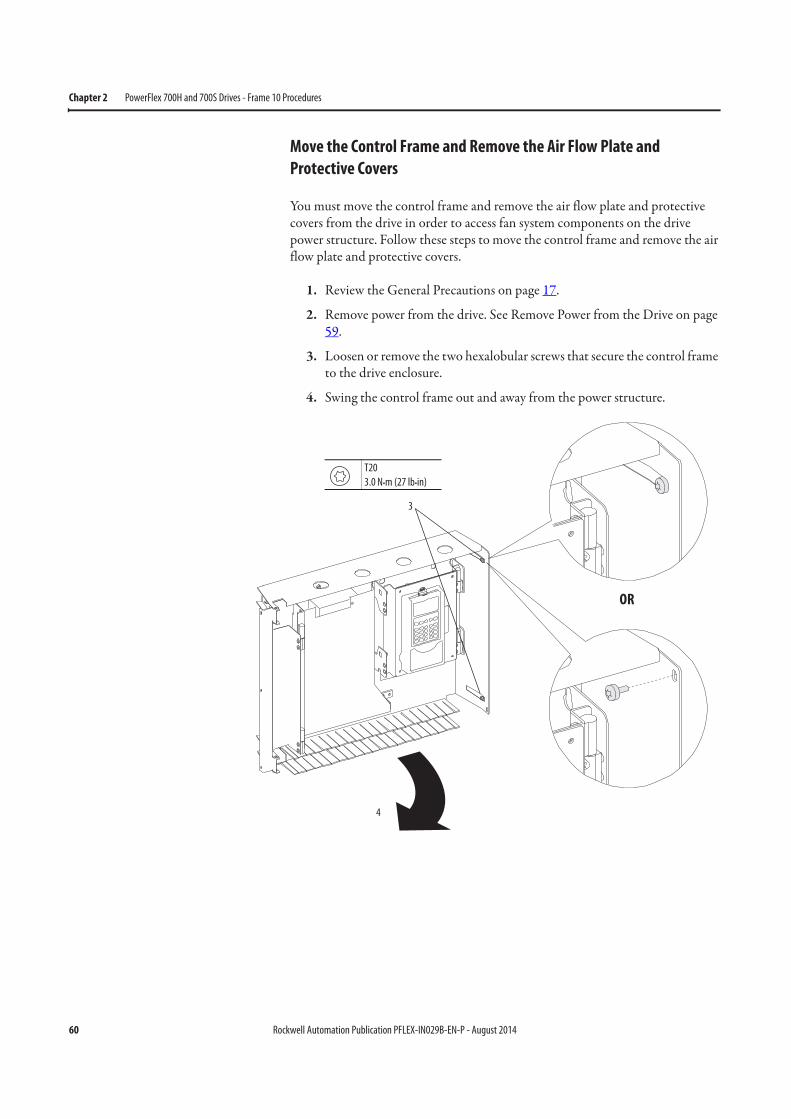
60 Rockwell Automation Publication PFLEX-IN029B-EN-P - August 2014
Chapter 2 PowerFlex 700H and 700S Drives - Frame 10 Procedures
Move the Control Frame and Remove the Air Flow Plate and
Protective Covers
You must move the control frame and remove the air flow plate and protective covers from the drive in order to access fan system components on the drive power structure. Follow these steps to move the control frame and remove the air flow plate and protective covers.
1. Review the General Precautions on page 17.
2. Remove power from the drive. See Remove Power from the Drive on page 59.
3. Loosen or remove the two hexalobular screws that secure the control frame to the drive enclosure.
4. Swing the control frame out and away from the power structure.
OR
3
4
T20
3.0 N•m (27 lb•in)
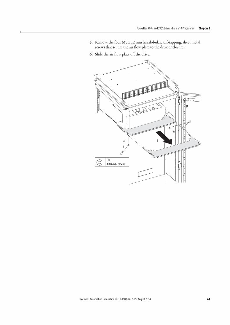
Rockwell Automation Publication PFLEX-IN029B-EN-P - August 2014 61
PowerFlex 700H and 700S Drives - Frame 10 Procedures Chapter 2
5. Remove the four M5 x 12 mm hexalobular, self-tapping, sheet metal screws that secure the air flow plate to the drive enclosure.
6. Slide the air flow plate off the drive.
5
5
T20
3.0 N•m (27 lb•in)
6
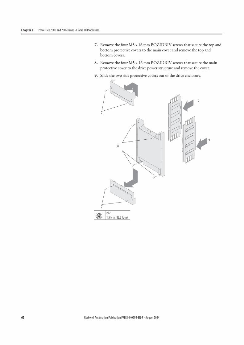
62 Rockwell Automation Publication PFLEX-IN029B-EN-P - August 2014
Chapter 2 PowerFlex 700H and 700S Drives - Frame 10 Procedures
7. Remove the four M5 x 16 mm POZIDRIV screws that secure the top and bottom protective covers to the main cover and remove the top and bottom covers.
8. Remove the four M5 x 16 mm POZIDRIV screws that secure the main protective cover to the drive power structure and remove the cover.
9. Slide the two side protective covers out of the drive enclosure.
7
7
8
9
PZ2
1.5 N•m (13.3 lb•in)
9
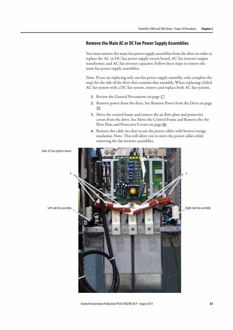
Rockwell Automation Publication PFLEX-IN029B-EN-P - August 2014 63
PowerFlex 700H and 700S Drives - Frame 10 Procedures Chapter 2
Remove the Main AC or DC Fan Power Supply Assemblies
You must remove the main fan power supply assemblies from the drive in order to replace the AC or DC fan power supply circuit board, AC fan inverter output transformer, and AC fan inverter capacitor. Follow these steps to remove the main fan power supply assemblies.
Note: If you are replacing only one fan power supply assembly, only complete the steps for the side of the drive that contains that assembly. When replacing a failed AC fan system with a DC fan system, remove and replace both AC fan systems.
1. Review the General Precautions on page 17.2. Remove power from the drive. See Remove Power from the Drive on page
59.3. Move the control frame and remove the air flow plate and protective
covers from the drive. See Move the Control Frame and Remove the Air Flow Plate and Protective Covers on page 60.
4. Remove the cable ties that secure the power cables with brown/orange insulation. Note: This will allow you to move the power cables while removing the fan inverter assemblies.
Left-side fan assembly Right-side fan assembly
4 4
Note: AC fan systems shown
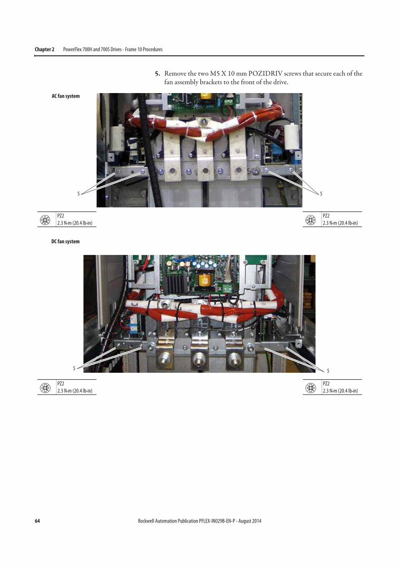
64 Rockwell Automation Publication PFLEX-IN029B-EN-P - August 2014
Chapter 2 PowerFlex 700H and 700S Drives - Frame 10 Procedures
5. Remove the two M5 X 10 mm POZIDRIV screws that secure each of the fan assembly brackets to the front of the drive.
5 5
PZ2
2.3 N•m (20.4 lb•in)
PZ2
2.3 N•m (20.4 lb•in)
AC fan system
5 5
DC fan system
PZ2
2.3 N•m (20.4 lb•in)
PZ2
2.3 N•m (20.4 lb•in)
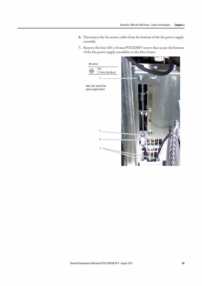
Rockwell Automation Publication PFLEX-IN029B-EN-P - August 2014 65
PowerFlex 700H and 700S Drives - Frame 10 Procedures Chapter 2
6. Disconnect the fan motor cables from the bottom of the fan power supply assembly.
7. Remove the four M5 x 10 mm POZIDRIV screws that secure the bottom of the fan power supply assemblies to the drive frame.
7
7
7
6
PZ2
2.3 N•m (20.4 lb•in)
All screws:
Note: Left- side AC fan power supply shown
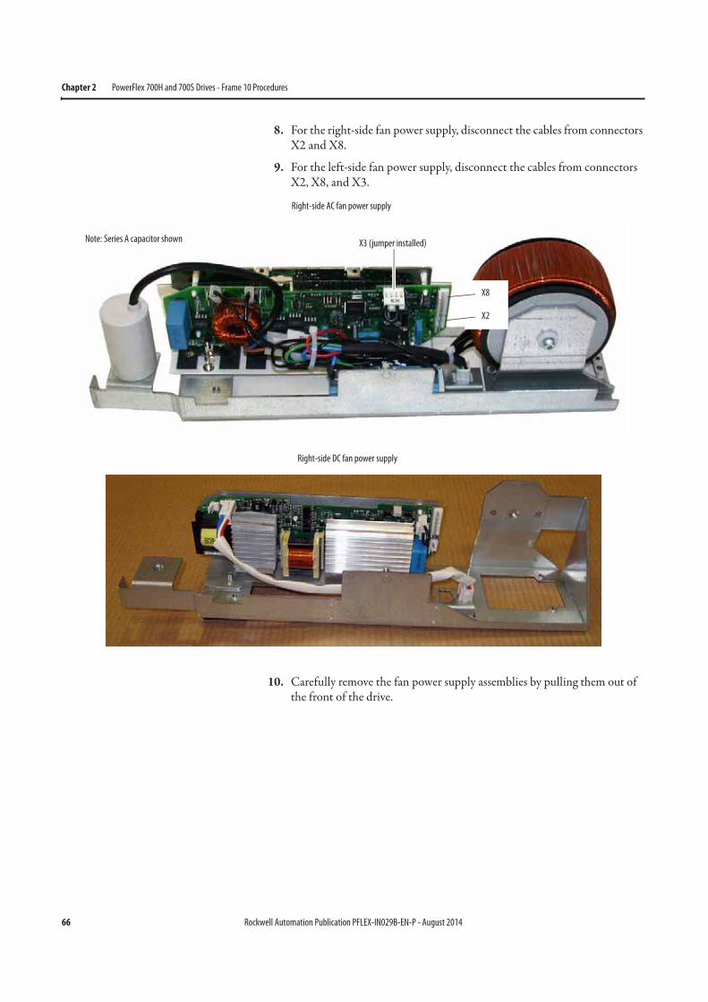
66 Rockwell Automation Publication PFLEX-IN029B-EN-P - August 2014
Chapter 2 PowerFlex 700H and 700S Drives - Frame 10 Procedures
8. For the right-side fan power supply, disconnect the cables from connectors X2 and X8.
9. For the left-side fan power supply, disconnect the cables from connectors X2, X8, and X3.
10. Carefully remove the fan power supply assemblies by pulling them out of the front of the drive.
X3 (jumper installed)
Right-side AC fan power supply
X8
X2
Note: Series A capacitor shown
Right-side DC fan power supply
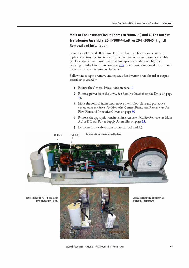
Rockwell Automation Publication PFLEX-IN029B-EN-P - August 2014 67
PowerFlex 700H and 700S Drives - Frame 10 Procedures Chapter 2
Main AC Fan Inverter Circuit Board (20-VB00299) and AC Fan Output
Transformer Assembly [20-FR10844 (Left) or 20-FR10845 (Right)]
Removal and Installation
PowerFlex 700H and 700S frame 10 drives have two fan inverters. You can replace a fan inverter circuit board, or replace an output transformer assembly (includes the output transformer and fan capacitor on the assembly). See Isolating a Faulty Fan Inverter on page 265 for test procedures used to determine if the circuit board requires replacement.
Follow these steps to remove and replace a fan inverter circuit board or output transformer assembly.
1. Review the General Precautions on page 17.
2. Remove power from the drive. See Remove Power from the Drive on page 59.
3. Move the control frame and remove the air flow plate and protective covers from the drive. See Move the Control Frame and Remove the Air Flow Plate and Protective Covers on page 60.
4. Remove the appropriate main fan inverter assembly. See Remove the Main AC or DC Fan Power Supply Assemblies on page 63.
5. Disconnect the cables from connectors X4 and X5.
X4 (Blue) X5 (Black)
Series B capacitor in a left-side AC faninverter assembly shown.
Series A capacitor in a left-side AC fan inverter assembly shown
Right-side AC fan inverter assembly shown
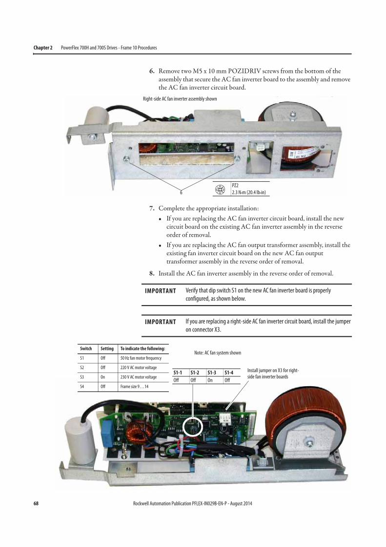
68 Rockwell Automation Publication PFLEX-IN029B-EN-P - August 2014
Chapter 2 PowerFlex 700H and 700S Drives - Frame 10 Procedures
6. Remove two M5 x 10 mm POZIDRIV screws from the bottom of the assembly that secure the AC fan inverter board to the assembly and remove the AC fan inverter circuit board.
7. Complete the appropriate installation:• If you are replacing the AC fan inverter circuit board, install the new
circuit board on the existing AC fan inverter assembly in the reverse order of removal.
• If you are replacing the AC fan output transformer assembly, install the existing fan inverter circuit board on the new AC fan output transformer assembly in the reverse order of removal.
8. Install the AC fan inverter assembly in the reverse order of removal.
6
PZ2
2.3 N•m (20.4 lb•in)
Right-side AC fan inverter assembly shown
IMPORTANT Verify that dip switch S1 on the new AC fan inverter board is properly
configured, as shown below.
IMPORTANT If you are replacing a right-side AC fan inverter circuit board, install the jumper
on connector X3.
S1-1 S1-2 S1-3 S1-4
Off Off On Off
Install jumper on X3 for right-side fan inverter boards
Switch Setting To indicate the following:
S1 Off 50 Hz fan motor frequency
S2 Off 220 V AC motor voltage
S3 On 230 V AC motor voltage
S4 Off Frame size 9…14
Note: AC fan system shown
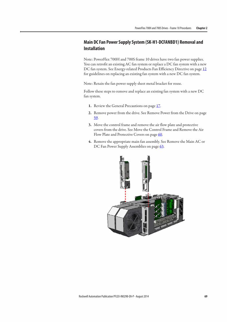
Rockwell Automation Publication PFLEX-IN029B-EN-P - August 2014 69
PowerFlex 700H and 700S Drives - Frame 10 Procedures Chapter 2
Main DC Fan Power Supply System (SK-H1-DCFANBD1) Removal and
Installation
Note: PowerFlex 700H and 700S frame 10 drives have two fan power supplies. You can retrofit an existing AC fan system or replace a DC fan system with a new DC fan system. See Energy-related Products Fan Efficiency Directive on page 12 for guidelines on replacing an existing fan system with a new DC fan system.
Note: Retain the fan power supply sheet metal bracket for reuse.
Follow these steps to remove and replace an existing fan system with a new DC fan system.
1. Review the General Precautions on page 17.
2. Remove power from the drive. See Remove Power from the Drive on page 59.
3. Move the control frame and remove the air flow plate and protective covers from the drive. See Move the Control Frame and Remove the Air Flow Plate and Protective Covers on page 60.
4. Remove the appropriate main fan assembly. See Remove the Main AC or DC Fan Power Supply Assemblies on page 63.
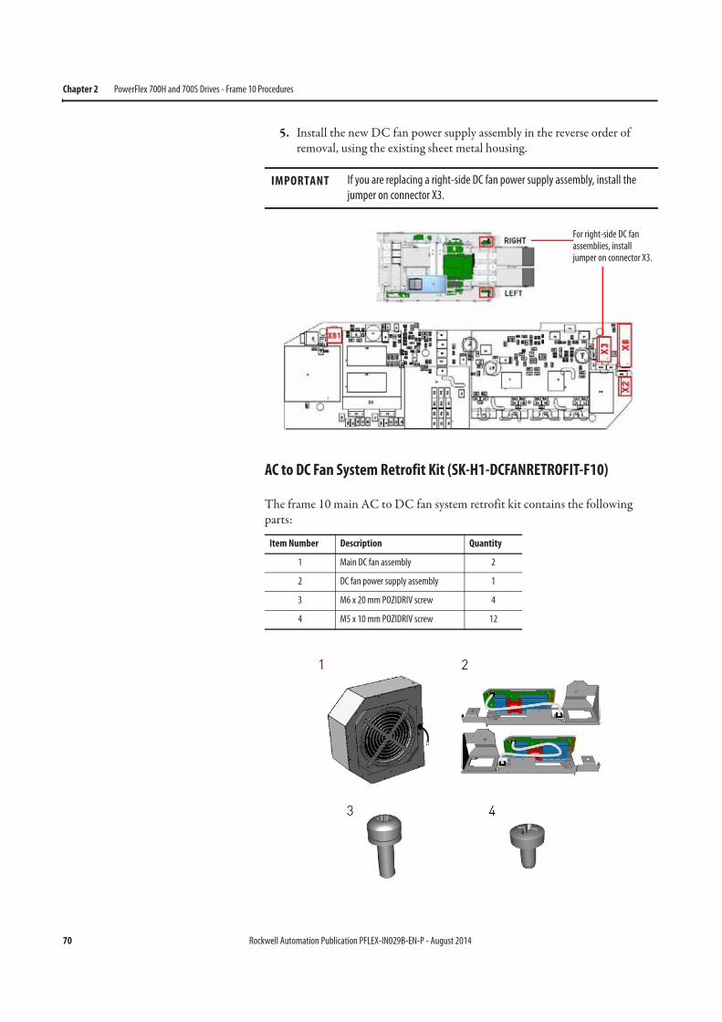
70 Rockwell Automation Publication PFLEX-IN029B-EN-P - August 2014
Chapter 2 PowerFlex 700H and 700S Drives - Frame 10 Procedures
5. Install the new DC fan power supply assembly in the reverse order of removal, using the existing sheet metal housing.
AC to DC Fan System Retrofit Kit (SK-H1-DCFANRETROFIT-F10)
The frame 10 main AC to DC fan system retrofit kit contains the following parts:
IMPORTANT If you are replacing a right-side DC fan power supply assembly, install the
jumper on connector X3.
Item Number Description Quantity
1 Main DC fan assembly 2
2 DC fan power supply assembly 1
3 M6 x 20 mm POZIDRIV screw 4
4 M5 x 10 mm POZIDRIV screw 12
For right-side DC fan assemblies, install jumper on connector X3.
Rockwell Automation Publication PFLEX-IN029B-EN-P - August 2014 71
PowerFlex 700H and 700S Drives - Frame 10 Procedures Chapter 2
Follow these steps to remove the main AC fan system and replace it with a main DC fan system.
1. Review the General Precautions on page 17.
2. Remove power from the drive. See Remove Power from the Drive on page 59.
3. Move the control frame and remove the air flow plate and protective covers from the drive. See Move the Control Frame and Remove the Air Flow Plate and Protective Covers on page 60.
4. Remove the main AC fan power supply assemblies. See Remove the Main AC or DC Fan Power Supply Assemblies on page 63.
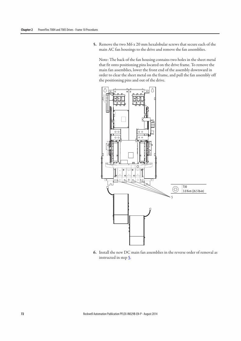
72 Rockwell Automation Publication PFLEX-IN029B-EN-P - August 2014
Chapter 2 PowerFlex 700H and 700S Drives - Frame 10 Procedures
5. Remove the two M6 x 20 mm hexalobular screws that secure each of the main AC fan housings to the drive and remove the fan assemblies.
Note: The back of the fan housing contains two holes in the sheet metal that fit onto positioning pins located on the drive frame. To remove the main fan assemblies, lower the front end of the assembly downward in order to clear the sheet metal on the frame, and pull the fan assembly off the positioning pins and out of the drive.
6. Install the new DC main fan assemblies in the reverse order of removal as instructed in step 5.
5
T30
3.0 N•m (26.5 lb•in)
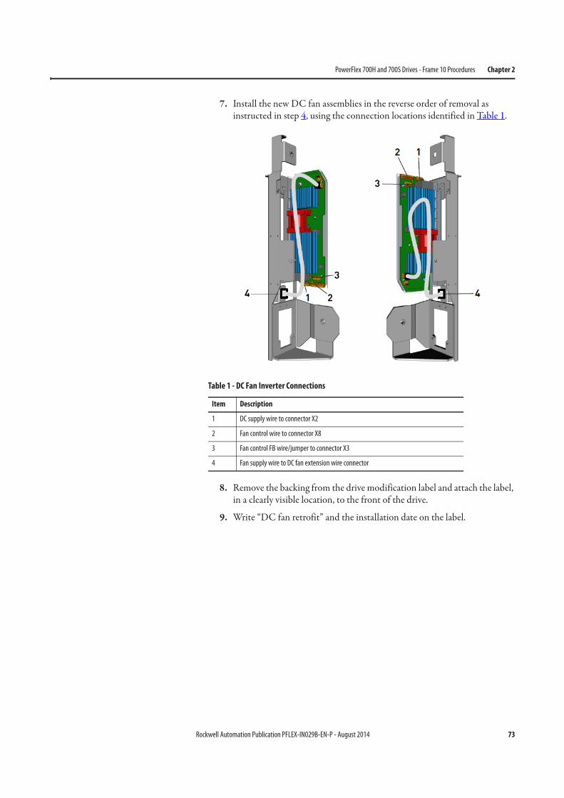
Rockwell Automation Publication PFLEX-IN029B-EN-P - August 2014 73
PowerFlex 700H and 700S Drives - Frame 10 Procedures Chapter 2
7. Install the new DC fan assemblies in the reverse order of removal as instructed in step 4, using the connection locations identified in Table 1.
8. Remove the backing from the drive modification label and attach the label, in a clearly visible location, to the front of the drive.
9. Write “DC fan retrofit” and the installation date on the label.
Table 1 - DC Fan Inverter Connections
Item Description
1 DC supply wire to connector X2
2 Fan control wire to connector X8
3 Fan control FB wire/jumper to connector X3
4 Fan supply wire to DC fan extension wire connector
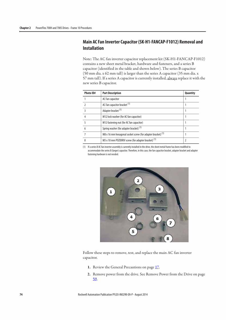
74 Rockwell Automation Publication PFLEX-IN029B-EN-P - August 2014
Chapter 2 PowerFlex 700H and 700S Drives - Frame 10 Procedures
Main AC Fan Inverter Capacitor (SK-H1-FANCAP-F1012) Removal and
Installation
Note: The AC fan inverter capacitor replacement kit (SK-H1-FANCAP-F1012) contains a new sheet metal bracket, hardware and fasteners, and a series B capacitor (identified in the table and shown below). The series B capacitor(50 mm dia. x 62 mm tall) is larger than the series A capacitor (35 mm dia. x57 mm tall). If a series A capacitor is currently installed, always replace it with the new series B capacitor.
Follow these steps to remove, test, and replace the main AC fan inverter capacitor.
1. Review the General Precautions on page 17.
2. Remove power from the drive. See Remove Power from the Drive on page 59.
Photo ID# Part Description Quantity
1 AC Fan capacitor 1
2 AC Fan capacitor bracket (1)
(1) If a series B AC fan inverter assembly is currently installed in the drive, the sheet metal frame has been modified to
accommodate the series B (larger) capacitor. Therefore, in this case, the fan capacitor bracket, adapter bracket and adapter
fastening hardware is not needed.
1
3 Adapter bracket (1) 1
4 M12 lock washer (for AC fan capacitor) 1
5 M12 fastening nut (for AC fan capacitor) 1
6 Spring washer (for adapter bracket) (1) 1
7 M8 x 16 mm hexagonal socket screw (for adapter bracket) (1) 1
8 M5 x 10 mm POZIDRIV screw (for adapter bracket) (1) 2
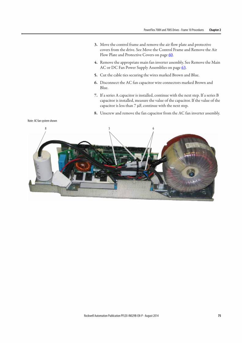
Rockwell Automation Publication PFLEX-IN029B-EN-P - August 2014 75
PowerFlex 700H and 700S Drives - Frame 10 Procedures Chapter 2
3. Move the control frame and remove the air flow plate and protective covers from the drive. See Move the Control Frame and Remove the Air Flow Plate and Protective Covers on page 60.
4. Remove the appropriate main fan inverter assembly. See Remove the Main AC or DC Fan Power Supply Assemblies on page 63.
5. Cut the cable ties securing the wires marked Brown and Blue.
6. Disconnect the AC fan capacitor wire connectors marked Brown and Blue.
7. If a series A capacitor is installed, continue with the next step. If a series B capacitor is installed, measure the value of the capacitor. If the value of the capacitor is less than 7 μF, continue with the next step.
8. Unscrew and remove the fan capacitor from the AC fan inverter assembly.
658
Note: AC fan system shown
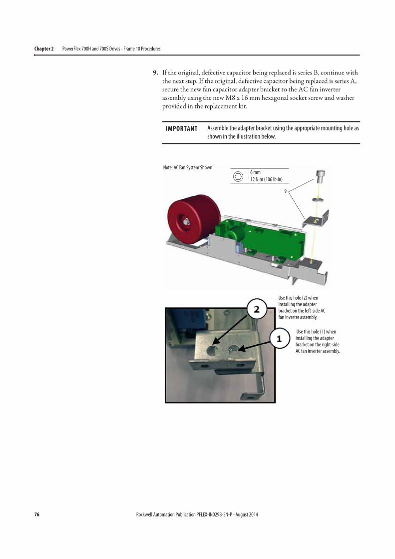
76 Rockwell Automation Publication PFLEX-IN029B-EN-P - August 2014
Chapter 2 PowerFlex 700H and 700S Drives - Frame 10 Procedures
9. If the original, defective capacitor being replaced is series B, continue with the next step. If the original, defective capacitor being replaced is series A, secure the new fan capacitor adapter bracket to the AC fan inverter assembly using the new M8 x 16 mm hexagonal socket screw and washer provided in the replacement kit.
IMPORTANT Assemble the adapter bracket using the appropriate mounting hole as
shown in the illustration below.
6 mm
12 N•m (106 lb•in)
9
Use this hole (1) when installing the adapter bracket on the right-side AC fan inverter assembly.
Use this hole (2) when installing the adapter bracket on the left-side AC fan inverter assembly.
Note: AC Fan System Shown
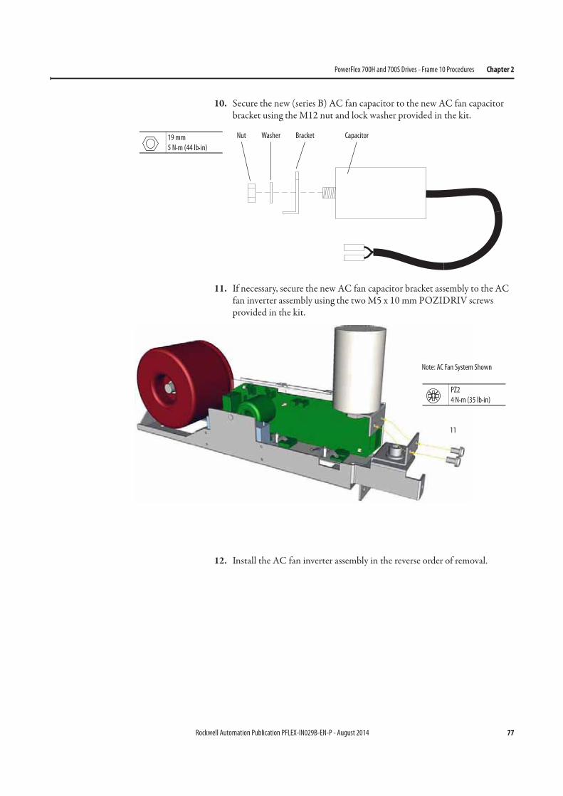
Rockwell Automation Publication PFLEX-IN029B-EN-P - August 2014 77
PowerFlex 700H and 700S Drives - Frame 10 Procedures Chapter 2
10. Secure the new (series B) AC fan capacitor to the new AC fan capacitor bracket using the M12 nut and lock washer provided in the kit.
11. If necessary, secure the new AC fan capacitor bracket assembly to the AC fan inverter assembly using the two M5 x 10 mm POZIDRIV screws provided in the kit.
12. Install the AC fan inverter assembly in the reverse order of removal.
19 mm
5 N•m (44 lb•in)
Nut Washer Bracket Capacitor
PZ2
4 N•m (35 lb•in)
11
Note: AC Fan System Shown
78 Rockwell Automation Publication PFLEX-IN029B-EN-P - August 2014
Chapter 2 PowerFlex 700H and 700S Drives - Frame 10 Procedures
Main AC Fan (20-PP01080) and Main DC Fan (SK-Y1-DCFAN1) Assembly
Removal and Installation
Follow these steps to measure the resistance between the main fan supply wires and remove and replace the main fan, if necessary.
Notes:• The fan replacement kit only contains the fan motor and impeller
assembly. Therefore, the sheet metal housing for the fan must be reused. • To identify which fan is installed in your drive, see Fan Inverter System
Block Diagrams on page 257.
1. Review the General Precautions on page 17.
2. Remove power from the drive. See Remove Power from the Drive on page 59.
3. Remove the bottom protective cover only from the drive. See Move the Control Frame and Remove the Air Flow Plate and Protective Covers on page 60.
4. Disconnect the fan power supply cable from the bottom of the fan assembly for each main fan (see the illustration on the following page for connection location).
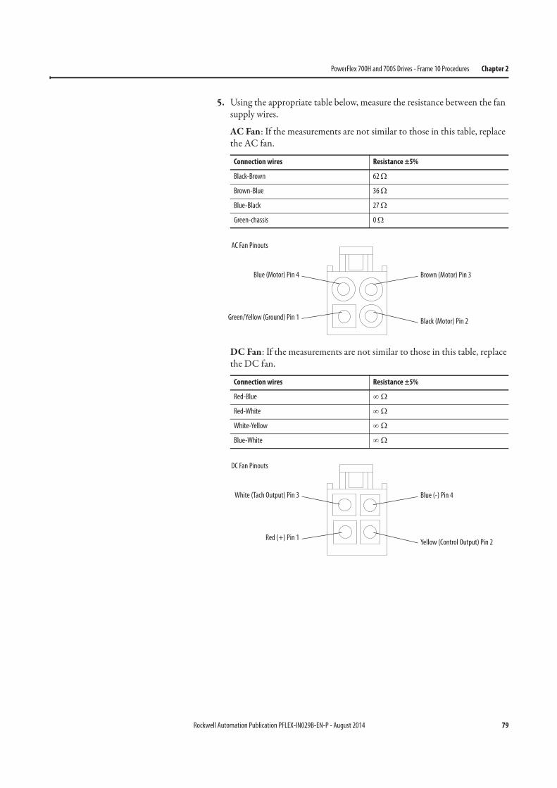
Rockwell Automation Publication PFLEX-IN029B-EN-P - August 2014 79
PowerFlex 700H and 700S Drives - Frame 10 Procedures Chapter 2
5. Using the appropriate table below, measure the resistance between the fan supply wires.
AC Fan: If the measurements are not similar to those in this table, replace the AC fan.
DC Fan: If the measurements are not similar to those in this table, replace the DC fan.
Connection wires Resistance ±5%
Black-Brown 62 Ω
Brown-Blue 36 Ω
Blue-Black 27 Ω
Green-chassis 0 Ω
Connection wires Resistance ±5%
Red-Blue ∞ Ω
Red-White ∞ Ω
White-Yellow ∞ Ω
Blue-White ∞ Ω
Blue (Motor) Pin 4
Green/Yellow (Ground) Pin 1
Brown (Motor) Pin 3
Black (Motor) Pin 2
AC Fan Pinouts
White (Tach Output) Pin 3
Red (+) Pin 1
Blue (-) Pin 4
Yellow (Control Output) Pin 2
DC Fan Pinouts
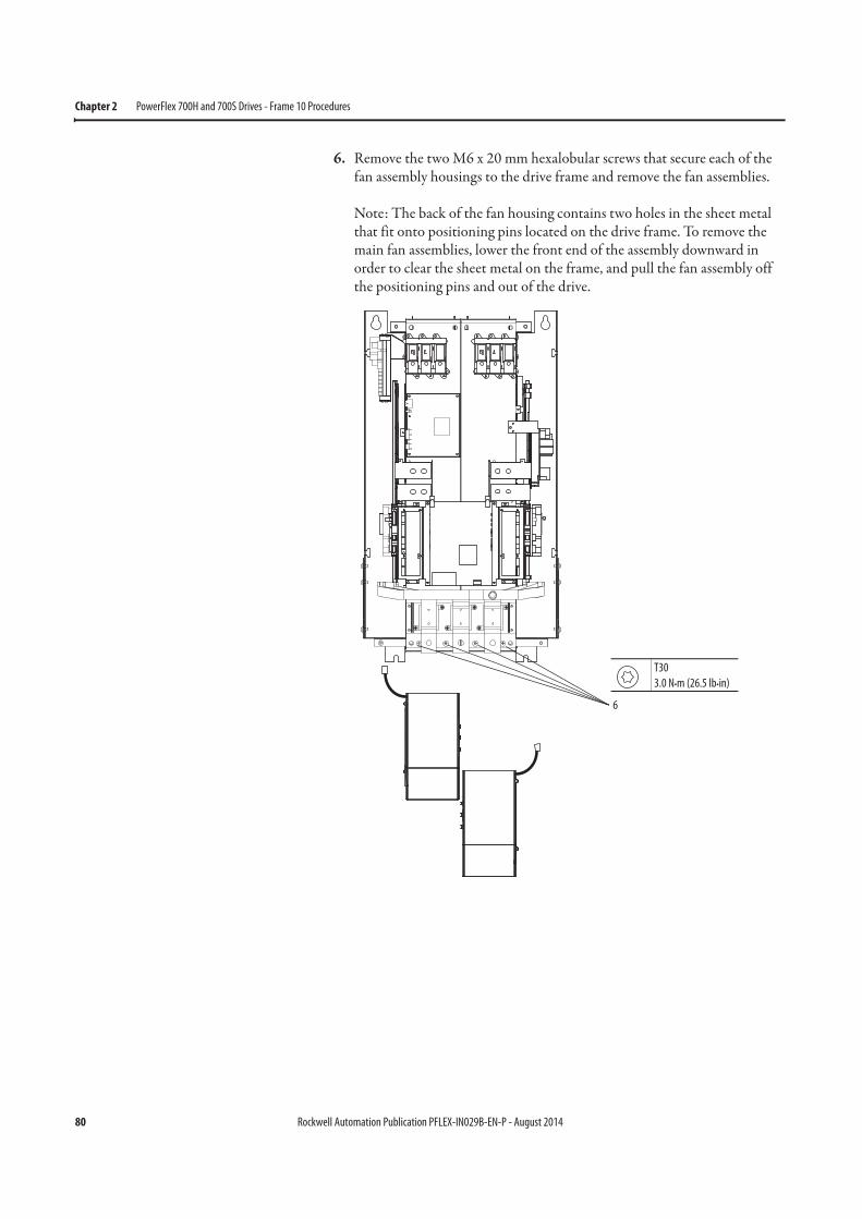
80 Rockwell Automation Publication PFLEX-IN029B-EN-P - August 2014
Chapter 2 PowerFlex 700H and 700S Drives - Frame 10 Procedures
6. Remove the two M6 x 20 mm hexalobular screws that secure each of the fan assembly housings to the drive frame and remove the fan assemblies.
Note: The back of the fan housing contains two holes in the sheet metal that fit onto positioning pins located on the drive frame. To remove the main fan assemblies, lower the front end of the assembly downward in order to clear the sheet metal on the frame, and pull the fan assembly off the positioning pins and out of the drive.
6
T30
3.0 N•m (26.5 lb•in)
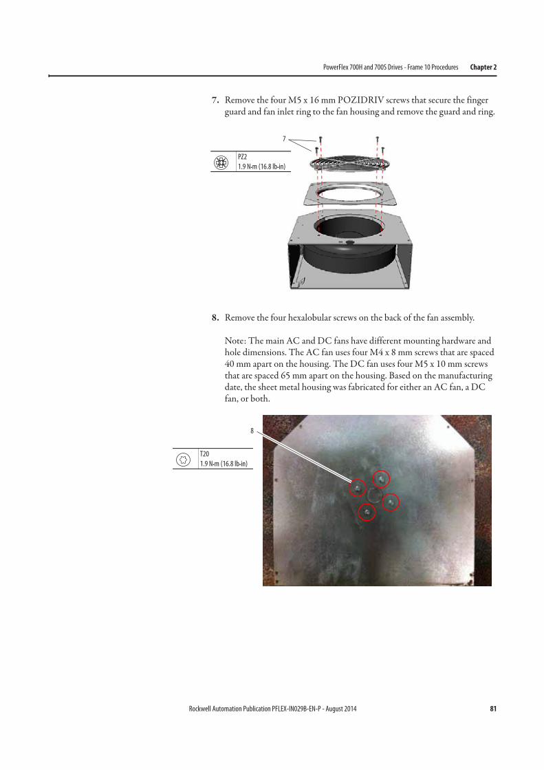
Rockwell Automation Publication PFLEX-IN029B-EN-P - August 2014 81
PowerFlex 700H and 700S Drives - Frame 10 Procedures Chapter 2
7. Remove the four M5 x 16 mm POZIDRIV screws that secure the finger guard and fan inlet ring to the fan housing and remove the guard and ring.
8. Remove the four hexalobular screws on the back of the fan assembly.
Note: The main AC and DC fans have different mounting hardware and hole dimensions. The AC fan uses four M4 x 8 mm screws that are spaced 40 mm apart on the housing. The DC fan uses four M5 x 10 mm screws that are spaced 65 mm apart on the housing. Based on the manufacturing date, the sheet metal housing was fabricated for either an AC fan, a DC fan, or both.
7
PZ2
1.9 N•m (16.8 lb•in)
8
T20
1.9 N•m (16.8 lb•in)

82 Rockwell Automation Publication PFLEX-IN029B-EN-P - August 2014
Chapter 2 PowerFlex 700H and 700S Drives - Frame 10 Procedures
9. Remove the three rubber bushings that hold the fan wiring to the sheet metal housing.
10. Slide the fan out of the sheet metal housing. Retain the sheet metal housing for reuse.
11. Install the new main fan in the reverse order of removal.
Verify that the fan turns easily and does not make contact with the sheet metal housing before installing the fan assembly on the drive.
ASIC Circuit Board Assembly Cooling Fan (20-PP01096) Removal and
Installation
The ASIC circuit board cooling fan is located on the ASIC board assembly on the upper, left-side of the drive. Follow these steps to remove and replace the cooling fan.
1. Review the General Precautions on page 17.
2. Remove power from the drive. See Remove Power from the Drive on page 59.
3. Move the control frame and remove the air flow plate and protective covers from the drive. See Move the Control Frame and Remove the Air Flow Plate and Protective Covers on page 60.
9
9
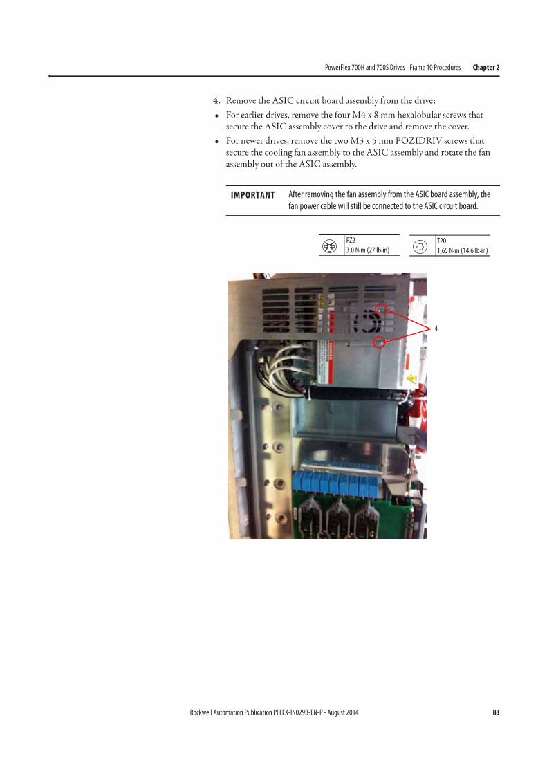
Rockwell Automation Publication PFLEX-IN029B-EN-P - August 2014 83
PowerFlex 700H and 700S Drives - Frame 10 Procedures Chapter 2
4. Remove the ASIC circuit board assembly from the drive:• For earlier drives, remove the four M4 x 8 mm hexalobular screws that
secure the ASIC assembly cover to the drive and remove the cover.• For newer drives, remove the two M3 x 5 mm POZIDRIV screws that
secure the cooling fan assembly to the ASIC assembly and rotate the fan assembly out of the ASIC assembly.
IMPORTANT After removing the fan assembly from the ASIC board assembly, the
fan power cable will still be connected to the ASIC circuit board.
PZ2
3.0 N•m (27 lb•in)
4
T20
1.65 N•m (14.6 lb•in)
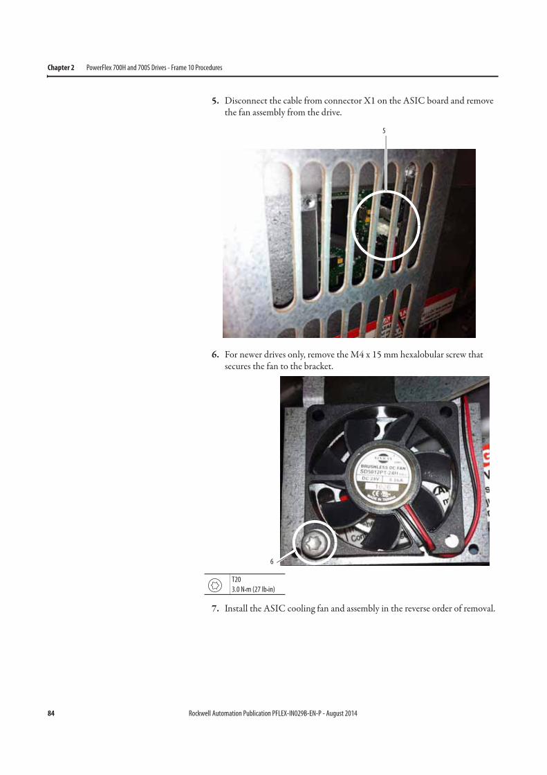
84 Rockwell Automation Publication PFLEX-IN029B-EN-P - August 2014
Chapter 2 PowerFlex 700H and 700S Drives - Frame 10 Procedures
5. Disconnect the cable from connector X1 on the ASIC board and remove the fan assembly from the drive.
6. For newer drives only, remove the M4 x 15 mm hexalobular screw that secures the fan to the bracket.
7. Install the ASIC cooling fan and assembly in the reverse order of removal.
5
6
T20
3.0 N•m (27 lb•in)
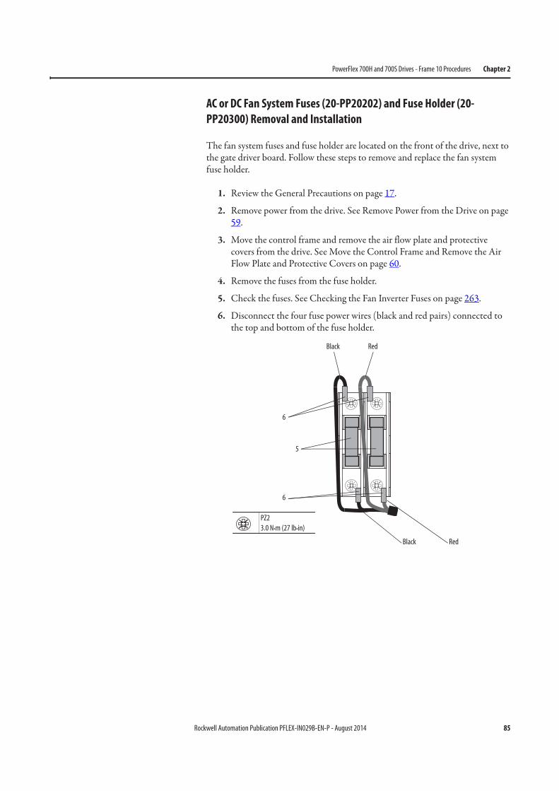
Rockwell Automation Publication PFLEX-IN029B-EN-P - August 2014 85
PowerFlex 700H and 700S Drives - Frame 10 Procedures Chapter 2
AC or DC Fan System Fuses (20-PP20202) and Fuse Holder (20-
PP20300) Removal and Installation
The fan system fuses and fuse holder are located on the front of the drive, next to the gate driver board. Follow these steps to remove and replace the fan system fuse holder.
1. Review the General Precautions on page 17.
2. Remove power from the drive. See Remove Power from the Drive on page 59.
3. Move the control frame and remove the air flow plate and protective covers from the drive. See Move the Control Frame and Remove the Air Flow Plate and Protective Covers on page 60.
4. Remove the fuses from the fuse holder.
5. Check the fuses. See Checking the Fan Inverter Fuses on page 263.
6. Disconnect the four fuse power wires (black and red pairs) connected to the top and bottom of the fuse holder.
6
6
RedBlack
RedBlack
PZ2
3.0 N•m (27 lb•in)
5
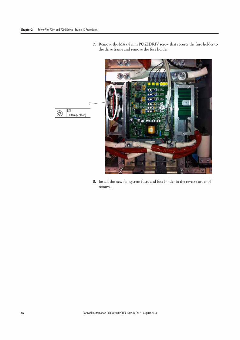
86 Rockwell Automation Publication PFLEX-IN029B-EN-P - August 2014
Chapter 2 PowerFlex 700H and 700S Drives - Frame 10 Procedures
7. Remove the M4 x 8 mm POZIDRIV screw that secures the fuse holder to the drive frame and remove the fuse holder.
8. Install the new fan system fuses and fuse holder in the reverse order of removal.
7
PZ2
3.0 N•m (27 lb•in)
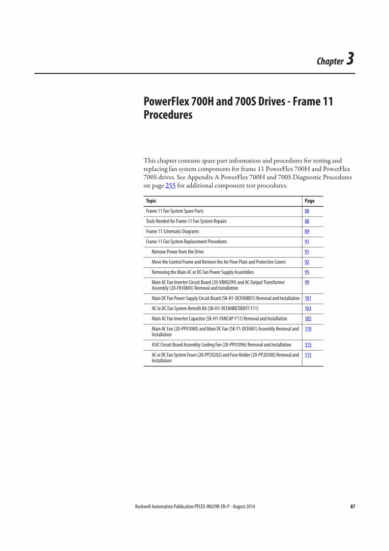
Rockwell Automation Publication PFLEX-IN029B-EN-P - August 2014 87
Chapter 3
PowerFlex 700H and 700S Drives - Frame 11 Procedures
This chapter contains spare part information and procedures for testing and replacing fan system components for frame 11 PowerFlex 700H and PowerFlex 700S drives. See Appendix A PowerFlex 700H and 700S Diagnostic Procedures on page 255 for additional component test procedures.
Topic Page
Frame 11 Fan System Spare Parts 88
Tools Needed for Frame 11 Fan System Repairs 88
Frame 11 Schematic Diagrams 89
Frame 11 Fan System Replacement Procedures 91
Remove Power from the Drive 91
Move the Control Frame and Remove the Air Flow Plate and Protective Covers 92
Removing the Main AC or DC Fan Power Supply Assemblies 95
Main AC Fan Inverter Circuit Board (20-VB00299) and AC Output Transformer Assembly (20-FR10845) Removal and Installation
99
Main DC Fan Power Supply Circuit Board (SK-H1-DCFANBD1) Removal and Installation 101
AC to DC Fan System Retrofit Kit (SK-H1-DCFANRETROFIT-F11) 103
Main AC Fan Inverter Capacitor (SK-H1-FANCAP-F11) Removal and Installation 105
Main AC Fan (20-PP01080) and Main DC Fan (SK-Y1-DCFAN1) Assembly Removal and Installation
110
ASIC Circuit Board Assembly Cooling Fan (20-PP01096) Removal and Installation 113
AC or DC Fan System Fuses (20-PP20202) and Fuse Holder (20-PP20300) Removal and Installation
115
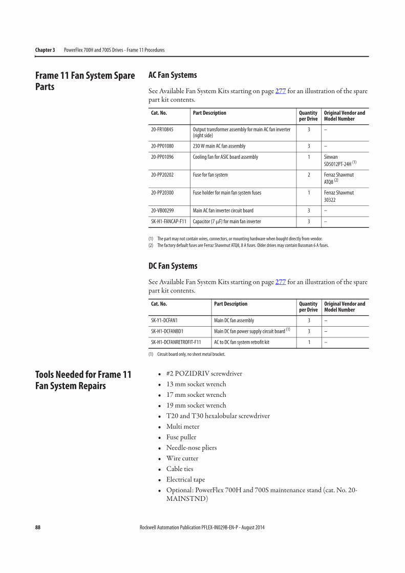
88 Rockwell Automation Publication PFLEX-IN029B-EN-P - August 2014
Chapter 3 PowerFlex 700H and 700S Drives - Frame 11 Procedures
Frame 11 Fan System Spare Parts
AC Fan Systems
See Available Fan System Kits starting on page 277 for an illustration of the spare part kit contents.
DC Fan Systems
See Available Fan System Kits starting on page 277 for an illustration of the spare part kit contents.
Tools Needed for Frame 11 Fan System Repairs
• #2 POZIDRIV screwdriver• 13 mm socket wrench• 17 mm socket wrench• 19 mm socket wrench• T20 and T30 hexalobular screwdriver• Multi meter• Fuse puller• Needle-nose pliers• Wire cutter• Cable ties• Electrical tape• Optional: PowerFlex 700H and 700S maintenance stand (cat. No. 20-
MAINSTND)
Cat. No. Part Description Quantity per Drive
Original Vendor and Model Number
20-FR10845 Output transformer assembly for main AC fan inverter (right side)
3 –
20-PP01080 230 W main AC fan assembly 3 –
20-PP01096 Cooling fan for ASIC board assembly 1 Sinwan
SD5012PT-24H (1)
(1) The part may not contain wires, connectors, or mounting hardware when bought directly from vendor.
20-PP20202 Fuse for fan system 2 Ferraz Shawmut
ATQ8 (2)
(2) The factory default fuses are Ferraz Shawmut ATQ8, 8 A fuses. Older drives may contain Bussman 6 A fuses.
20-PP20300 Fuse holder for main fan system fuses 1 Ferraz Shawmut
30322
20-VB00299 Main AC fan inverter circuit board 3 –
SK-H1-FANCAP-F11 Capacitor (7 μF) for main fan inverter 3 –
Cat. No. Part Description Quantity per Drive
Original Vendor and Model Number
SK-Y1-DCFAN1 Main DC fan assembly 3 –
SK-H1-DCFANBD1 Main DC fan power supply circuit board (1)
(1) Circuit board only, no sheet metal bracket.
3 –
SK-H1-DCFANRETROFIT-F11 AC to DC fan system retrofit kit 1 –
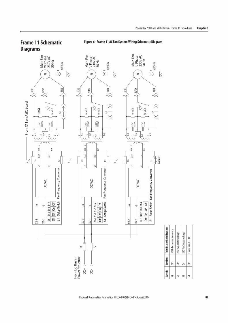
Rockwell Automation Publication PFLEX-IN029B-EN-P - August 2014 89
PowerFlex 700H and 700S Drives - Frame 11 Procedures Chapter 3
Frame 11 Schematic Diagrams
Figure 6 - Frame 11 AC Fan System Wiring Schematic Diagram
(+)
DC/
AC
X8 X3
U1 V1
X4-1
X5-1
(-)X2
-1
BLK
300V
AC
300V
AC1
BLK
2
3 BLK
BLK
2.2
f4BL
K5
2.2
f
7f
10 M
10 M
6
BLK
3
(+)
DC/
AC
X8 X3
U1 V1
X4-1
X5-1
(-)X2
-1
X2-3
BLK
300V
AC
300V
AC1
BLK
2
3 BLK
BLK
2.2
f4BL
K5
2.2
f
7 f
10 M
10 M
6
BLK
3
(+)
DC/
AC
Fan
Freq
uenc
y Co
nver
ter
Fan
Freq
uenc
y Co
nver
ter
X8 X3
U1 V1
X4-1
X5-1
(-)X2
-1
X2-3
BLK
300V
AC
300V
AC1
BLK
2
3 BLK
BLK
2.2
f4BL
K5
2.2
f
7f
10 M
10 M
6
BLK
24
3 Jum
per
From
DC
Bus i
nPo
wer
Stru
ctur
e
DC+
DC-
F1 F2
Off
S1-1
Off
S1-2
On
S1-3
Off
S1-4
S1 -
Setu
p Sw
itch
Off
S1-1
Off
S1-2
On
S1-3
Off
S1-4
S1 -
Setu
p Sw
itch
Off
S1-1
Off
S1-2
On
S1-3
Off
S1-4
S1 -
Setu
p Sw
itch
Fan
Freq
uenc
y Co
nver
ter
Fan
Freq
uenc
y Co
nver
ter
Mai
n Fa
nW
Pha
se23
0V A
C50
Hz
Mai
n Fa
nV
Phas
e23
0V A
C50
Hz
Mai
n Fa
nU
Phas
e23
0V A
C50
Hz
From
X11
on
ASIC
Boa
rd
X2-3
1BR
N
BLUE
2
BLAC
K3
YLW
/GRN
4
M
1BR
N
BLUE
2
BLAC
K3
YLW
/GRN
4
M
1BR
N
BLUE
2
BLAC
K3
YLW
/GRN
4
M
Swit
chSe
ttin
gTo
indi
cate
th
e fo
llow
ing:
S1O
ff50
Hz
fan
mot
or fr
eque
ncy
S2O
ff22
0 V
AC m
otor
vol
tage
S3O
n23
0 V
AC m
otor
vol
tage
S4O
ffFr
ame
size
9…
14
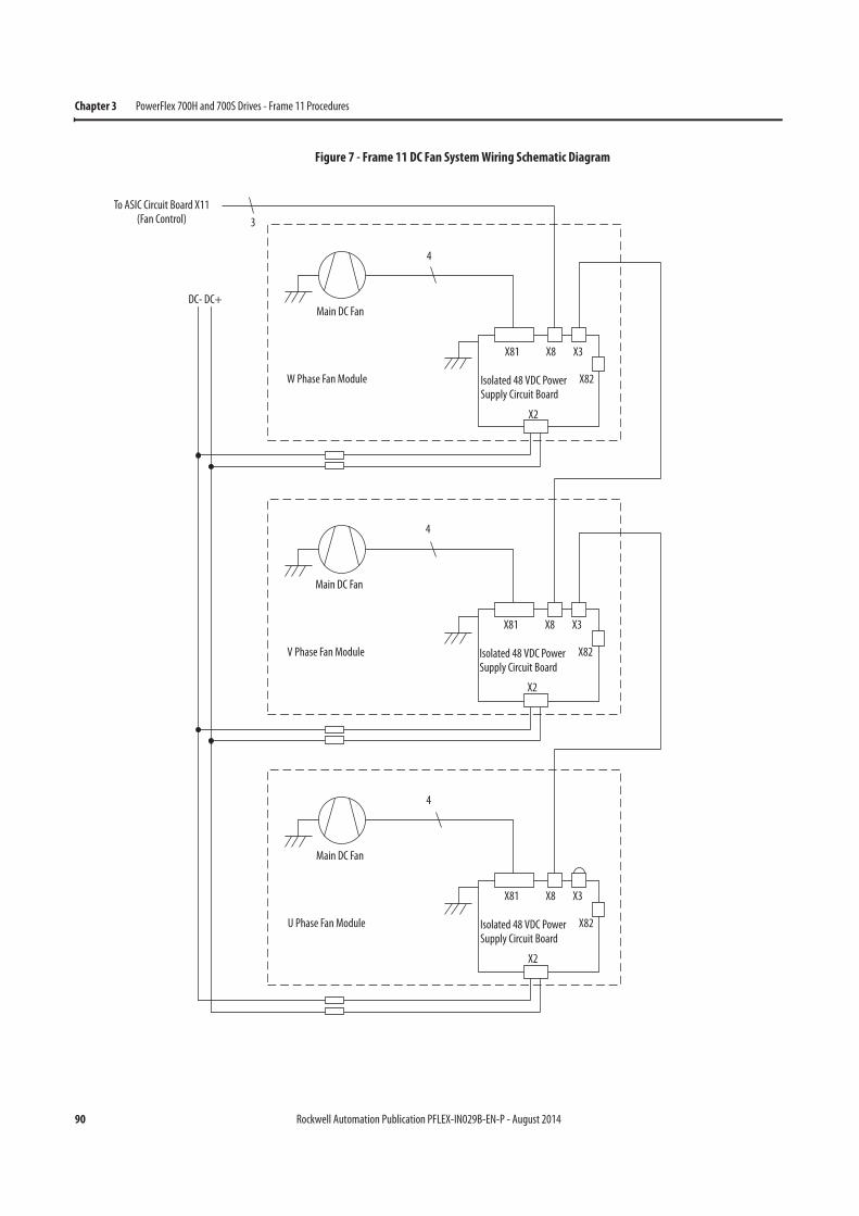
90 Rockwell Automation Publication PFLEX-IN029B-EN-P - August 2014
Chapter 3 PowerFlex 700H and 700S Drives - Frame 11 Procedures
Figure 7 - Frame 11 DC Fan System Wiring Schematic Diagram
3
To ASIC Circuit Board X11(Fan Control)
4
Main DC Fan
W Phase Fan Module
DC- DC+
Isolated 48 VDC Power Supply Circuit Board
X81 X8 X3
X82
X2
4
Main DC Fan
V Phase Fan Module Isolated 48 VDC Power Supply Circuit Board
X81 X8 X3
X82
X2
4
Main DC Fan
U Phase Fan Module Isolated 48 VDC Power Supply Circuit Board
X81 X8 X3
X82
X2
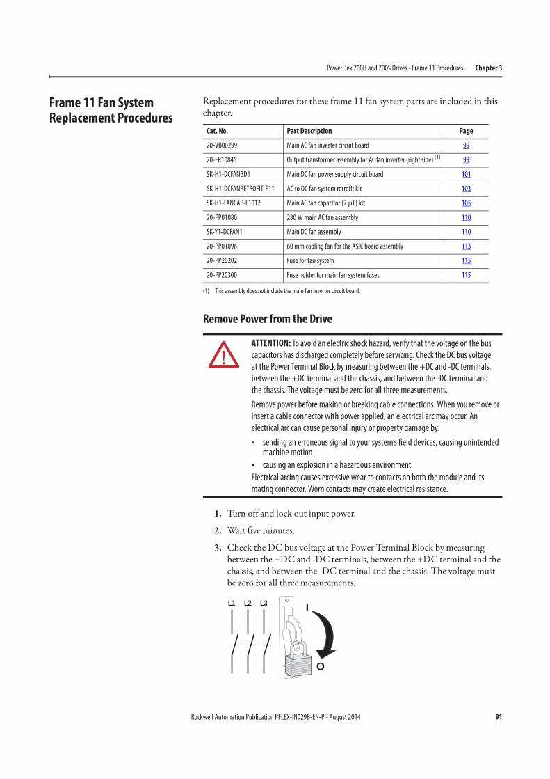
Rockwell Automation Publication PFLEX-IN029B-EN-P - August 2014 91
PowerFlex 700H and 700S Drives - Frame 11 Procedures Chapter 3
Frame 11 Fan System Replacement Procedures
Replacement procedures for these frame 11 fan system parts are included in this chapter.
Remove Power from the Drive
1. Turn off and lock out input power.
2. Wait five minutes.
3. Check the DC bus voltage at the Power Terminal Block by measuring between the +DC and -DC terminals, between the +DC terminal and the chassis, and between the -DC terminal and the chassis. The voltage must be zero for all three measurements.
Cat. No. Part Description Page
20-VB00299 Main AC fan inverter circuit board 99
20-FR10845 Output transformer assembly for AC fan inverter (right side) (1)
(1) This assembly does not include the main fan inverter circuit board.
99
SK-H1-DCFANBD1 Main DC fan power supply circuit board 101
SK-H1-DCFANRETROFIT-F11 AC to DC fan system retrofit kit 103
SK-H1-FANCAP-F1012 Main AC fan capacitor (7 μF) kit 105
20-PP01080 230 W main AC fan assembly 110
SK-Y1-DCFAN1 Main DC fan assembly 110
20-PP01096 60 mm cooling fan for the ASIC board assembly 113
20-PP20202 Fuse for fan system 115
20-PP20300 Fuse holder for main fan system fuses 115
ATTENTION: To avoid an electric shock hazard, verify that the voltage on the bus
capacitors has discharged completely before servicing. Check the DC bus voltage
at the Power Terminal Block by measuring between the +DC and -DC terminals,
between the +DC terminal and the chassis, and between the -DC terminal and
the chassis. The voltage must be zero for all three measurements.
Remove power before making or breaking cable connections. When you remove or
insert a cable connector with power applied, an electrical arc may occur. An
electrical arc can cause personal injury or property damage by:
• sending an erroneous signal to your system’s field devices, causing unintended machine motion
• causing an explosion in a hazardous environment
Electrical arcing causes excessive wear to contacts on both the module and its
mating connector. Worn contacts may create electrical resistance.
L1 L2 L3
O
I
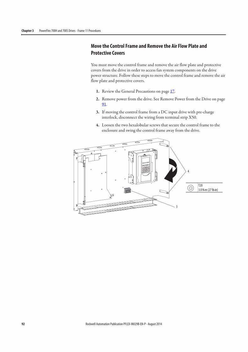
92 Rockwell Automation Publication PFLEX-IN029B-EN-P - August 2014
Chapter 3 PowerFlex 700H and 700S Drives - Frame 11 Procedures
Move the Control Frame and Remove the Air Flow Plate and
Protective Covers
You must move the control frame and remove the air flow plate and protective covers from the drive in order to access fan system components on the drive power structure. Follow these steps to move the control frame and remove the air flow plate and protective covers.
1. Review the General Precautions on page 17.
2. Remove power from the drive. See Remove Power from the Drive on page 91.
3. If moving the control frame from a DC input drive with pre-charge interlock, disconnect the wiring from terminal strip X50.
4. Loosen the two hexalobular screws that secure the control frame to the enclosure and swing the control frame away from the drive.
T20
3.0 N•m (27 lb•in)
4
3

Rockwell Automation Publication PFLEX-IN029B-EN-P - August 2014 93
PowerFlex 700H and 700S Drives - Frame 11 Procedures Chapter 3
5. Remove the four M5 x 12 mm hexalobular, self-tapping, sheet metal screws that secure the air flow plate to the drive enclosure and slide the plate off the drive.
5
T20
3.0 N•m (27 lb•in)
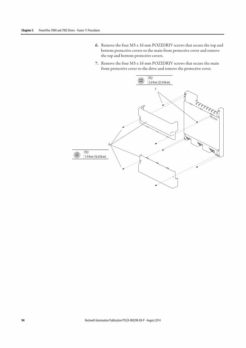
94 Rockwell Automation Publication PFLEX-IN029B-EN-P - August 2014
Chapter 3 PowerFlex 700H and 700S Drives - Frame 11 Procedures
6. Remove the four M5 x 16 mm POZIDRIV screws that secure the top and bottom protective covers to the main front protective cover and remove the top and bottom protective covers.
7. Remove the four M5 x 16 mm POZIDRIV screws that secure the main front protective cover to the drive and remove the protective cover.
6
PZ2
1.9 N•m (16.8 lb•in)
PZ2
2.6 N•m (23.0 lb•in)
7

Rockwell Automation Publication PFLEX-IN029B-EN-P - August 2014 95
PowerFlex 700H and 700S Drives - Frame 11 Procedures Chapter 3
Removing the Main AC or DC Fan Power Supply Assemblies
You must remove the main fan power supply assemblies from the drive in order to test and/or replace the AC or DC fan power supply circuit board, AC fan inverter output transformer, and/or AC fan inverter capacitor. Follow these steps to remove the main fan inverter assemblies.
Note: You only need to complete the steps necessary to remove the fan assembly (left side, center, or right side) you are testing or replacing.
1. Review the General Precautions on page 17.
2. Remove power from the drive. See Remove Power from the Drive on page 91.
3. Move the control frame and remove the air flow plate and protective covers. See Move the Control Frame and Remove the Air Flow Plate and Protective Covers on page 92.
Left SideFan Inverter
Center FanInverter
Right Side Fan Inverter
Note: AC FanSystems Shown
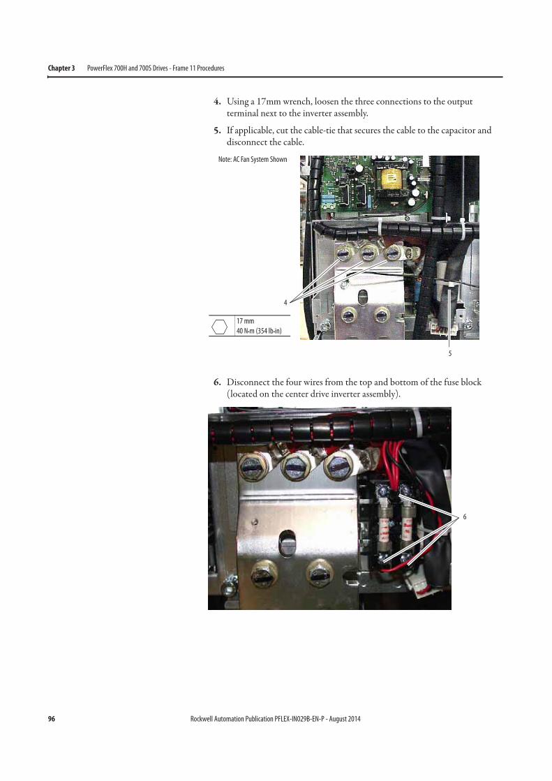
96 Rockwell Automation Publication PFLEX-IN029B-EN-P - August 2014
Chapter 3 PowerFlex 700H and 700S Drives - Frame 11 Procedures
4. Using a 17mm wrench, loosen the three connections to the output terminal next to the inverter assembly.
5. If applicable, cut the cable-tie that secures the cable to the capacitor and disconnect the cable.
6. Disconnect the four wires from the top and bottom of the fuse block (located on the center drive inverter assembly).
4
17 mm
40 N•m (354 lb•in)
5
Note: AC Fan System Shown
6

Rockwell Automation Publication PFLEX-IN029B-EN-P - August 2014 97
PowerFlex 700H and 700S Drives - Frame 11 Procedures Chapter 3
7. Remove the two M5 x 10 mm POZIDRIV screws that secure the fan power supply assembly to the front of the drive. Tightening torque for reassembly is 1.9 N•m (16.8 lb•in).
8. Disconnect the fan motor cable from the bottom of the fan power supply assembly.
9. Remove the four M5 x 10 mm POZIDRIV screws that secure the bottom of the fan power supply assembly to the drive frame.
9
9
9
8
PZ2
2.3 N•m (20.4 lb•in)
All Screws:
7
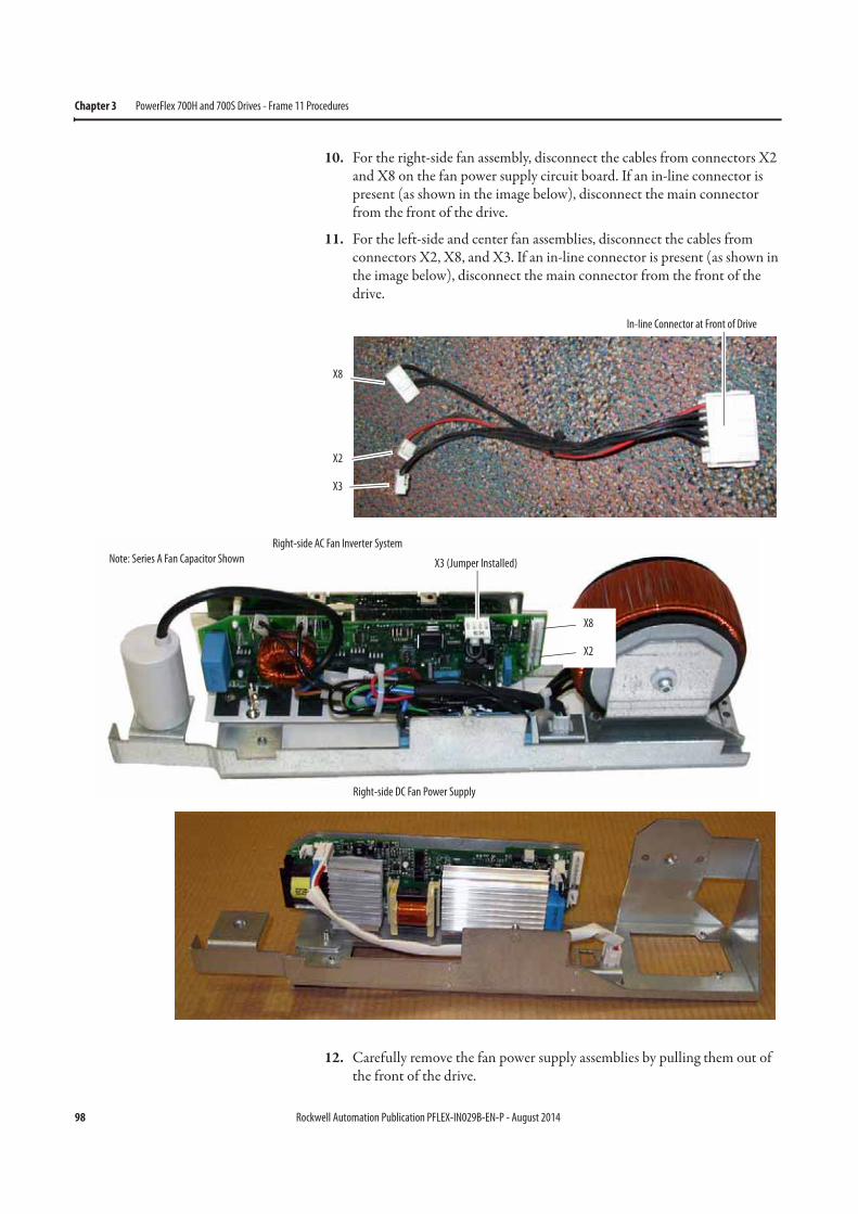
98 Rockwell Automation Publication PFLEX-IN029B-EN-P - August 2014
Chapter 3 PowerFlex 700H and 700S Drives - Frame 11 Procedures
10. For the right-side fan assembly, disconnect the cables from connectors X2 and X8 on the fan power supply circuit board. If an in-line connector is present (as shown in the image below), disconnect the main connector from the front of the drive.
11. For the left-side and center fan assemblies, disconnect the cables from connectors X2, X8, and X3. If an in-line connector is present (as shown in the image below), disconnect the main connector from the front of the drive.
12. Carefully remove the fan power supply assemblies by pulling them out of the front of the drive.
In-line Connector at Front of Drive
X8
X2
X3
X3 (Jumper Installed)
Right-side AC Fan Inverter System
X8
X2
Note: Series A Fan Capacitor Shown
Right-side DC Fan Power Supply
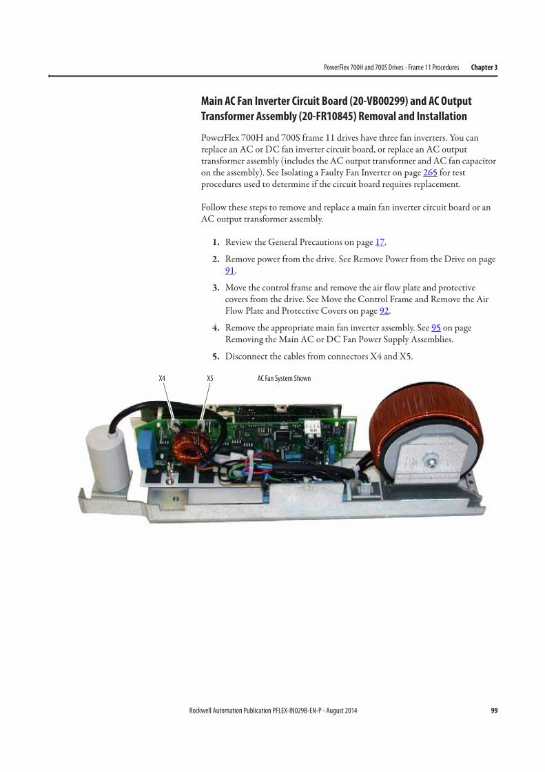
Rockwell Automation Publication PFLEX-IN029B-EN-P - August 2014 99
PowerFlex 700H and 700S Drives - Frame 11 Procedures Chapter 3
Main AC Fan Inverter Circuit Board (20-VB00299) and AC Output
Transformer Assembly (20-FR10845) Removal and Installation
PowerFlex 700H and 700S frame 11 drives have three fan inverters. You can replace an AC or DC fan inverter circuit board, or replace an AC output transformer assembly (includes the AC output transformer and AC fan capacitor on the assembly). See Isolating a Faulty Fan Inverter on page 265 for test procedures used to determine if the circuit board requires replacement.
Follow these steps to remove and replace a main fan inverter circuit board or an AC output transformer assembly.
1. Review the General Precautions on page 17.
2. Remove power from the drive. See Remove Power from the Drive on page 91.
3. Move the control frame and remove the air flow plate and protective covers from the drive. See Move the Control Frame and Remove the Air Flow Plate and Protective Covers on page 92.
4. Remove the appropriate main fan inverter assembly. See 95 on page Removing the Main AC or DC Fan Power Supply Assemblies.
5. Disconnect the cables from connectors X4 and X5.
X4 X5 AC Fan System Shown
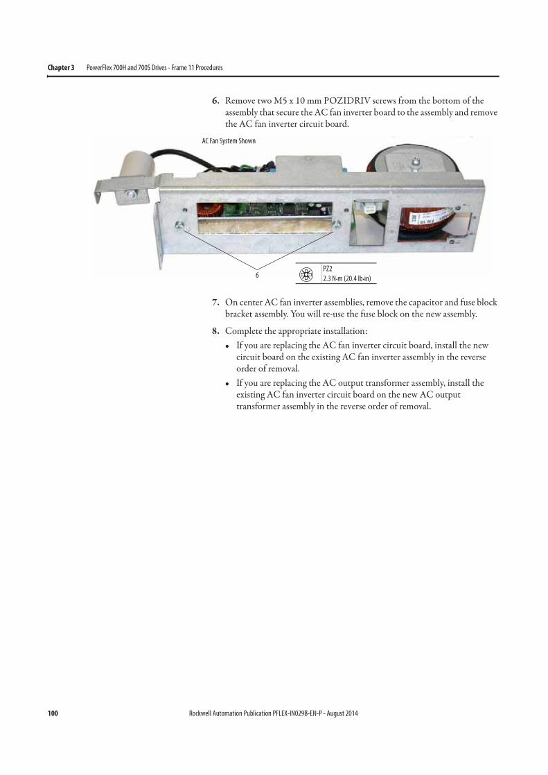
100 Rockwell Automation Publication PFLEX-IN029B-EN-P - August 2014
Chapter 3 PowerFlex 700H and 700S Drives - Frame 11 Procedures
6. Remove two M5 x 10 mm POZIDRIV screws from the bottom of the assembly that secure the AC fan inverter board to the assembly and remove the AC fan inverter circuit board.
7. On center AC fan inverter assemblies, remove the capacitor and fuse block bracket assembly. You will re-use the fuse block on the new assembly.
8. Complete the appropriate installation:• If you are replacing the AC fan inverter circuit board, install the new
circuit board on the existing AC fan inverter assembly in the reverse order of removal.
• If you are replacing the AC output transformer assembly, install the existing AC fan inverter circuit board on the new AC output transformer assembly in the reverse order of removal.
6PZ2
2.3 N•m (20.4 lb•in)
AC Fan System Shown
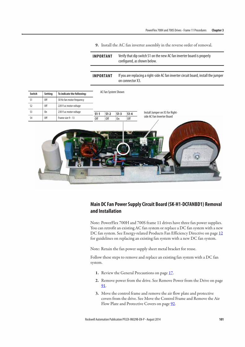
Rockwell Automation Publication PFLEX-IN029B-EN-P - August 2014 101
PowerFlex 700H and 700S Drives - Frame 11 Procedures Chapter 3
9. Install the AC fan inverter assembly in the reverse order of removal.
Main DC Fan Power Supply Circuit Board (SK-H1-DCFANBD1) Removal
and Installation
Note: PowerFlex 700H and 700S frame 11 drives have three fan power supplies. You can retrofit an existing AC fan system or replace a DC fan system with a new DC fan system. See Energy-related Products Fan Efficiency Directive on page 12 for guidelines on replacing an existing fan system with a new DC fan system.
Note: Retain the fan power supply sheet metal bracket for reuse.
Follow these steps to remove and replace an existing fan system with a DC fan system.
1. Review the General Precautions on page 17.
2. Remove power from the drive. See Remove Power from the Drive on page 91.
3. Move the control frame and remove the air flow plate and protective covers from the drive. See Move the Control Frame and Remove the Air Flow Plate and Protective Covers on page 92.
IMPORTANT Verify that dip switch S1 on the new AC fan inverter board is properly
configured, as shown below.
IMPORTANT If you are replacing a right-side AC fan inverter circuit board, install the jumper
on connector X3.
S1-1 S1-2 S1-3 S1-4
Off Off On Off
Install Jumper on X3 for Right-side AC Fan Inverter Board
Switch Setting To indicate the following:
S1 Off 50 Hz fan motor frequency
S2 Off 220 V ac motor voltage
S3 On 230 V ac motor voltage
S4 Off Frame size 9 - 13
AC Fan System Shown
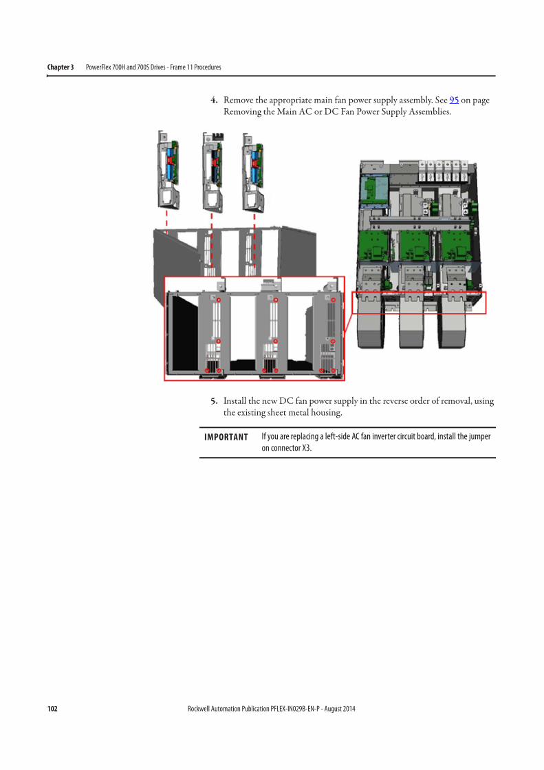
102 Rockwell Automation Publication PFLEX-IN029B-EN-P - August 2014
Chapter 3 PowerFlex 700H and 700S Drives - Frame 11 Procedures
4. Remove the appropriate main fan power supply assembly. See 95 on page Removing the Main AC or DC Fan Power Supply Assemblies.
5. Install the new DC fan power supply in the reverse order of removal, using the existing sheet metal housing.
IMPORTANT If you are replacing a left-side AC fan inverter circuit board, install the jumper
on connector X3.
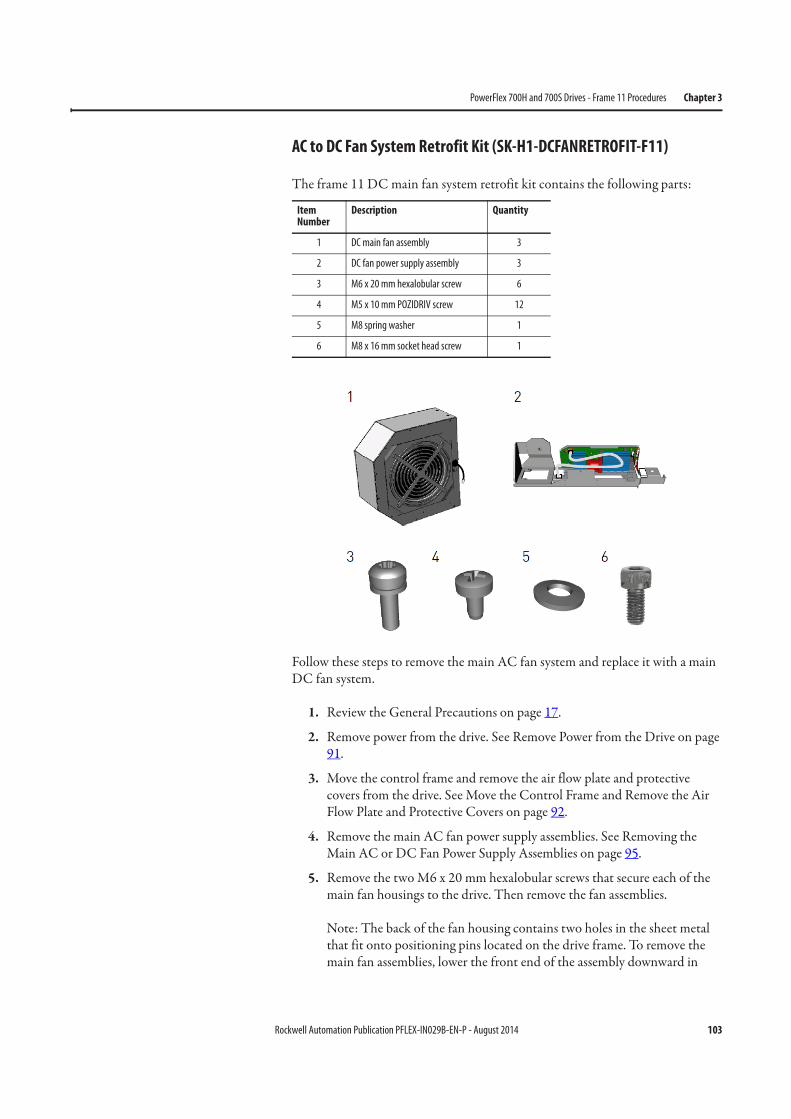
Rockwell Automation Publication PFLEX-IN029B-EN-P - August 2014 103
PowerFlex 700H and 700S Drives - Frame 11 Procedures Chapter 3
AC to DC Fan System Retrofit Kit (SK-H1-DCFANRETROFIT-F11)
The frame 11 DC main fan system retrofit kit contains the following parts:
Follow these steps to remove the main AC fan system and replace it with a main DC fan system.
1. Review the General Precautions on page 17.
2. Remove power from the drive. See Remove Power from the Drive on page 91.
3. Move the control frame and remove the air flow plate and protective covers from the drive. See Move the Control Frame and Remove the Air Flow Plate and Protective Covers on page 92.
4. Remove the main AC fan power supply assemblies. See Removing the Main AC or DC Fan Power Supply Assemblies on page 95.
5. Remove the two M6 x 20 mm hexalobular screws that secure each of the main fan housings to the drive. Then remove the fan assemblies.
Note: The back of the fan housing contains two holes in the sheet metal that fit onto positioning pins located on the drive frame. To remove the main fan assemblies, lower the front end of the assembly downward in
Item Number
Description Quantity
1 DC main fan assembly 3
2 DC fan power supply assembly 3
3 M6 x 20 mm hexalobular screw 6
4 M5 x 10 mm POZIDRIV screw 12
5 M8 spring washer 1
6 M8 x 16 mm socket head screw 1
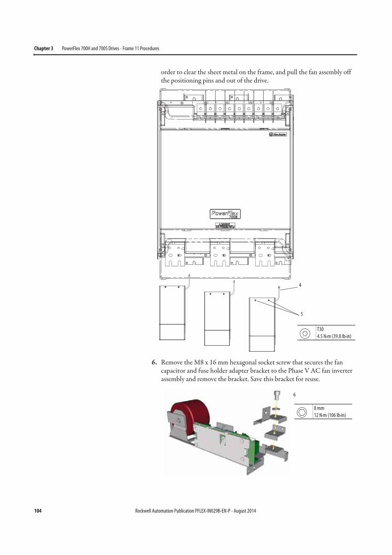
104 Rockwell Automation Publication PFLEX-IN029B-EN-P - August 2014
Chapter 3 PowerFlex 700H and 700S Drives - Frame 11 Procedures
order to clear the sheet metal on the frame, and pull the fan assembly off the positioning pins and out of the drive.
6. Remove the M8 x 16 mm hexagonal socket screw that secures the fan capacitor and fuse holder adapter bracket to the Phase V AC fan inverter assembly and remove the bracket. Save this bracket for reuse.
4
5
T30
4.5 N•m (39.8 lb•in)
8 mm
12 N•m (106 lb•in)
6
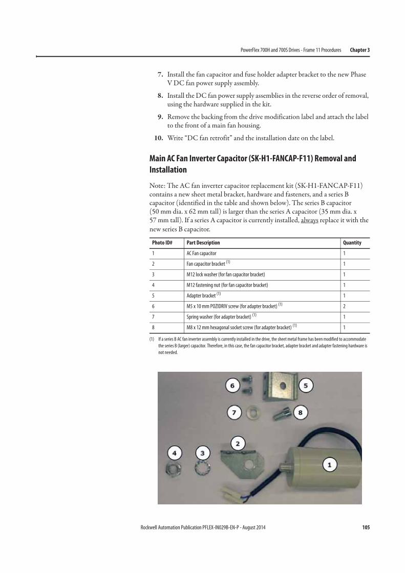
Rockwell Automation Publication PFLEX-IN029B-EN-P - August 2014 105
PowerFlex 700H and 700S Drives - Frame 11 Procedures Chapter 3
7. Install the fan capacitor and fuse holder adapter bracket to the new Phase V DC fan power supply assembly.
8. Install the DC fan power supply assemblies in the reverse order of removal, using the hardware supplied in the kit.
9. Remove the backing from the drive modification label and attach the label to the front of a main fan housing.
10. Write “DC fan retrofit” and the installation date on the label.
Main AC Fan Inverter Capacitor (SK-H1-FANCAP-F11) Removal and
Installation
Note: The AC fan inverter capacitor replacement kit (SK-H1-FANCAP-F11) contains a new sheet metal bracket, hardware and fasteners, and a series B capacitor (identified in the table and shown below). The series B capacitor(50 mm dia. x 62 mm tall) is larger than the series A capacitor (35 mm dia. x57 mm tall). If a series A capacitor is currently installed, always replace it with the new series B capacitor.
Photo ID# Part Description Quantity
1 AC Fan capacitor 1
2 Fan capacitor bracket (1)
(1) If a series B AC fan inverter assembly is currently installed in the drive, the sheet metal frame has been modified to accommodate
the series B (larger) capacitor. Therefore, in this case, the fan capacitor bracket, adapter bracket and adapter fastening hardware is
not needed.
1
3 M12 lock washer (for fan capacitor bracket) 1
4 M12 fastening nut (for fan capacitor bracket) 1
5 Adapter bracket (1) 1
6 M5 x 10 mm POZIDRIV screw (for adapter bracket) (1) 2
7 Spring washer (for adapter bracket) (1) 1
8 M8 x 12 mm hexagonal socket screw (for adapter bracket) (1) 1
106 Rockwell Automation Publication PFLEX-IN029B-EN-P - August 2014
Chapter 3 PowerFlex 700H and 700S Drives - Frame 11 Procedures
Follow these steps to remove, test, and replace the main AC fan inverter capacitor.
1. Review the General Precautions on page 17.
2. Remove power from the drive. See Remove Power from the Drive on page 91.
3. Move the control frame and remove the air flow plate and protective covers from the drive. See Move the Control Frame and Remove the Air Flow Plate and Protective Covers on page 92.
4. Remove the appropriate main AC fan inverter assembly. See Removing the Main AC or DC Fan Power Supply Assemblies on page 95.
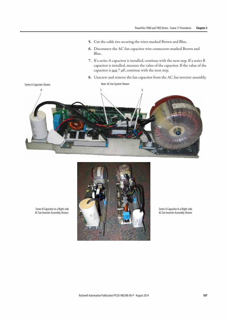
Rockwell Automation Publication PFLEX-IN029B-EN-P - August 2014 107
PowerFlex 700H and 700S Drives - Frame 11 Procedures Chapter 3
5. Cut the cable ties securing the wires marked Brown and Blue.
6. Disconnect the AC fan capacitor wire connectors marked Brown and Blue.
7. If a series A capacitor is installed, continue with the next step. If a series B capacitor is installed, measure the value of the capacitor. If the value of the capacitor is not 7 μF, continue with the next step.
8. Unscrew and remove the fan capacitor from the AC fan inverter assembly.
658
Series B Capacitor in a Right-sideAC Fan Inverter Assembly Shown.
Series A Capacitor in a Right-side AC Fan Inverter Assembly Shown
Series A Capacitor Shown Note: AC Fan System Shown
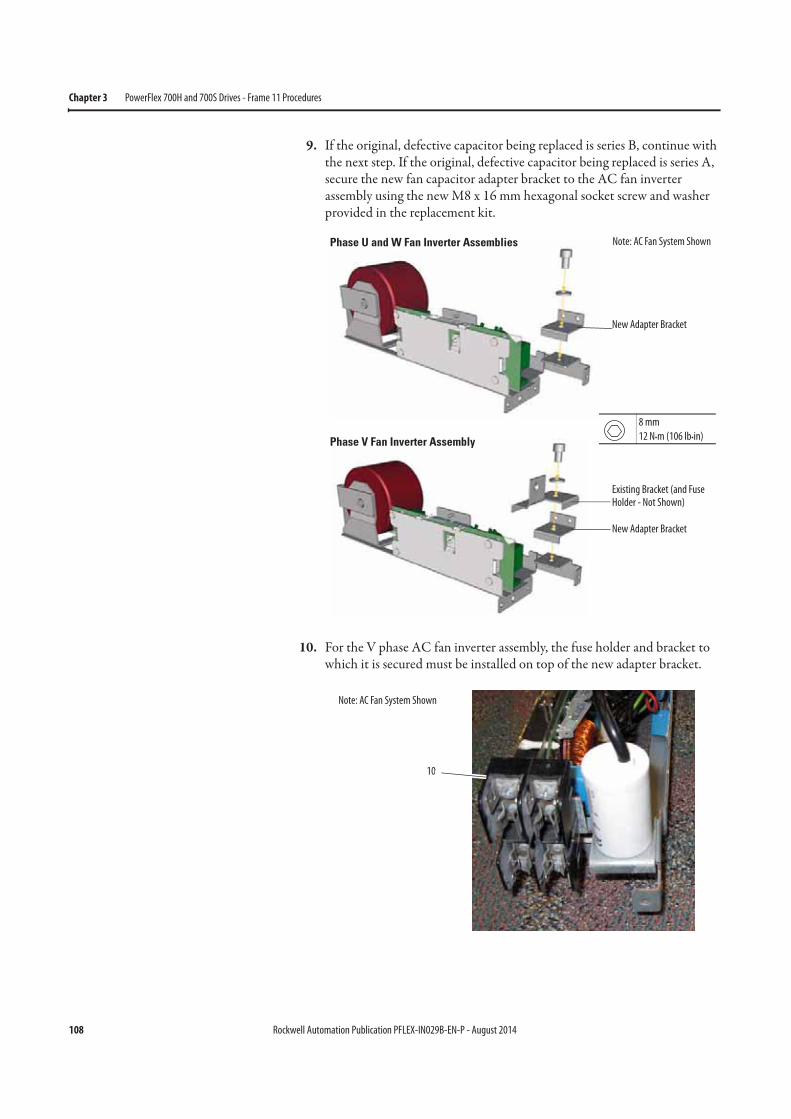
108 Rockwell Automation Publication PFLEX-IN029B-EN-P - August 2014
Chapter 3 PowerFlex 700H and 700S Drives - Frame 11 Procedures
9. If the original, defective capacitor being replaced is series B, continue with the next step. If the original, defective capacitor being replaced is series A, secure the new fan capacitor adapter bracket to the AC fan inverter assembly using the new M8 x 16 mm hexagonal socket screw and washer provided in the replacement kit.
10. For the V phase AC fan inverter assembly, the fuse holder and bracket to which it is secured must be installed on top of the new adapter bracket.
New Adapter Bracket
New Adapter Bracket
Existing Bracket (and Fuse Holder - Not Shown)
8 mm
12 N•m (106 lb•in)
Note: AC Fan System Shown
10
Note: AC Fan System Shown
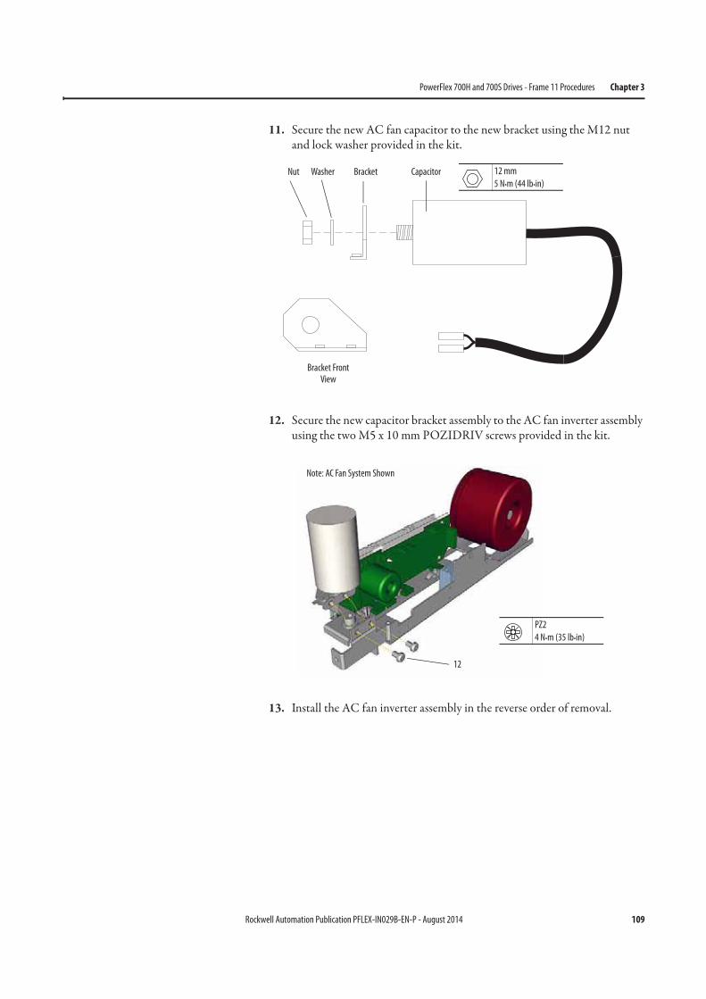
Rockwell Automation Publication PFLEX-IN029B-EN-P - August 2014 109
PowerFlex 700H and 700S Drives - Frame 11 Procedures Chapter 3
11. Secure the new AC fan capacitor to the new bracket using the M12 nut and lock washer provided in the kit.
12. Secure the new capacitor bracket assembly to the AC fan inverter assembly using the two M5 x 10 mm POZIDRIV screws provided in the kit.
13. Install the AC fan inverter assembly in the reverse order of removal.
Nut Washer Bracket Capacitor
Bracket Front View
12 mm
5 N•m (44 lb•in)
12
PZ2
4 N•m (35 lb•in)
Note: AC Fan System Shown
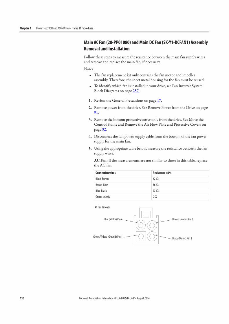
110 Rockwell Automation Publication PFLEX-IN029B-EN-P - August 2014
Chapter 3 PowerFlex 700H and 700S Drives - Frame 11 Procedures
Main AC Fan (20-PP01080) and Main DC Fan (SK-Y1-DCFAN1) Assembly
Removal and Installation
Follow these steps to measure the resistance between the main fan supply wires and remove and replace the main fan, if necessary.
Notes:• The fan replacement kit only contains the fan motor and impeller
assembly. Therefore, the sheet metal housing for the fan must be reused.• To identify which fan is installed in your drive, see Fan Inverter System
Block Diagrams on page 257.
1. Review the General Precautions on page 17.
2. Remove power from the drive. See Remove Power from the Drive on page 91.
3. Remove the bottom protective cover only from the drive. See Move the Control Frame and Remove the Air Flow Plate and Protective Covers on page 92.
4. Disconnect the fan power supply cable from the bottom of the fan power supply for the main fan.
5. Using the appropriate table below, measure the resistance between the fan supply wires.
AC Fan: If the measurements are not similar to those in this table, replace the AC fan.
Connection wires Resistance ±5%
Black-Brown 62 Ω
Brown-Blue 36 Ω
Blue-Black 27 Ω
Green-chassis 0 Ω
Blue (Motor) Pin 4
Green/Yellow (Ground) Pin 1
Brown (Motor) Pin 3
Black (Motor) Pin 2
AC Fan Pinouts
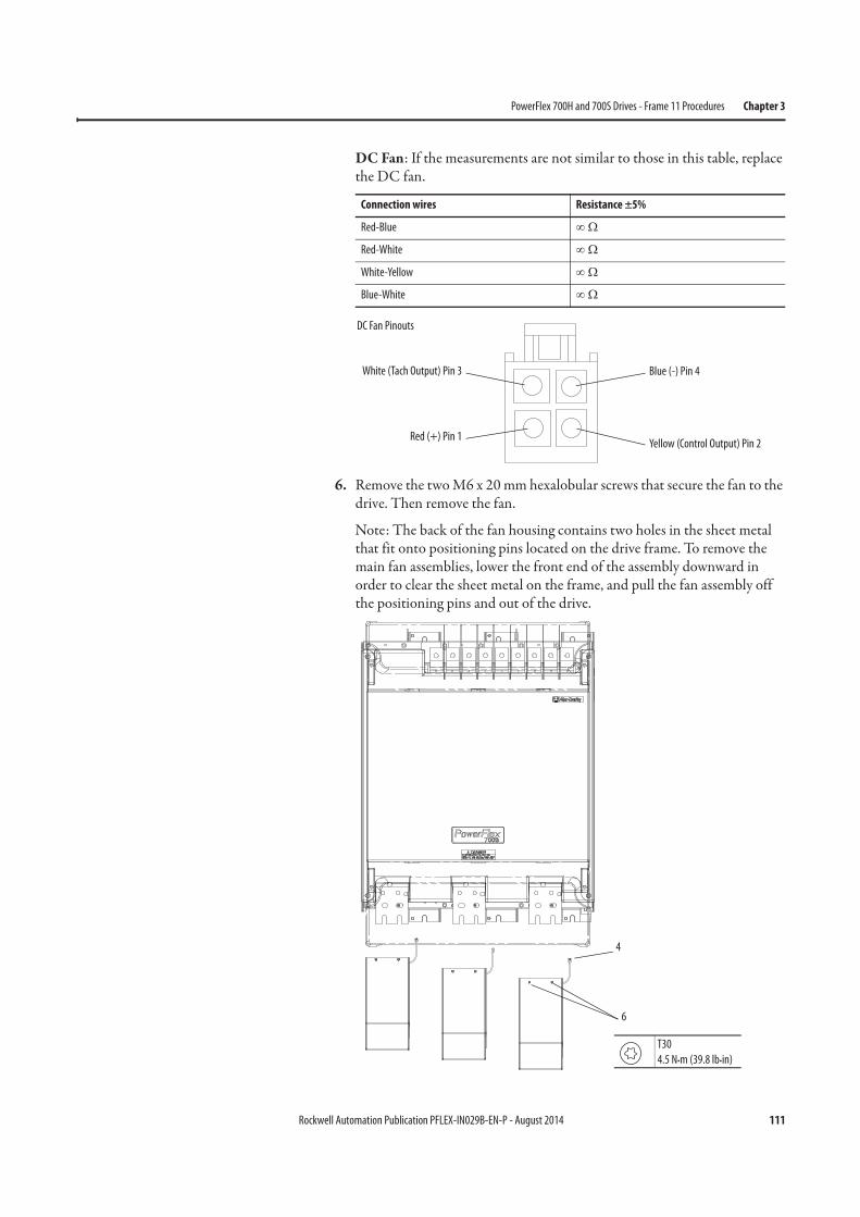
Rockwell Automation Publication PFLEX-IN029B-EN-P - August 2014 111
PowerFlex 700H and 700S Drives - Frame 11 Procedures Chapter 3
DC Fan: If the measurements are not similar to those in this table, replace the DC fan.
6. Remove the two M6 x 20 mm hexalobular screws that secure the fan to the drive. Then remove the fan.
Note: The back of the fan housing contains two holes in the sheet metal that fit onto positioning pins located on the drive frame. To remove the main fan assemblies, lower the front end of the assembly downward in order to clear the sheet metal on the frame, and pull the fan assembly off the positioning pins and out of the drive.
Connection wires Resistance ±5%
Red-Blue ∞ Ω
Red-White ∞ Ω
White-Yellow ∞ Ω
Blue-White ∞ Ω
White (Tach Output) Pin 3
Red (+) Pin 1
Blue (-) Pin 4
Yellow (Control Output) Pin 2
DC Fan Pinouts
4
6
T30
4.5 N•m (39.8 lb•in)

112 Rockwell Automation Publication PFLEX-IN029B-EN-P - August 2014
Chapter 3 PowerFlex 700H and 700S Drives - Frame 11 Procedures
7. Remove the four M5 x 16 mm POZIDRIV screws that secure the finger guard and fan inlet ring to the fan housing and remove the guard and ring.
8. Remove the four hexalobular screws on the back of the fan assembly.
Note: The Main AC and DC fans have different mounting hardware and hole dimensions. The AC fan uses four M4 x 8 mm screws that are spaced 40 mm apart on the housing. The DC fan uses four M5 x 10 mm screws that are spaced 65 mm apart on the housing. Based on the manufacturing date, the sheet metal housing was fabricated for either an AC fan, a DC fan, or both.
7
PZ2
2.6 N•m (23.0 lb•in)
8
T20
2.6 N•m (23 lb•in)
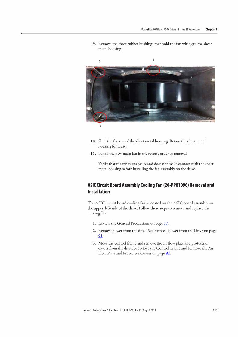
Rockwell Automation Publication PFLEX-IN029B-EN-P - August 2014 113
PowerFlex 700H and 700S Drives - Frame 11 Procedures Chapter 3
9. Remove the three rubber bushings that hold the fan wiring to the sheet metal housing.
10. Slide the fan out of the sheet metal housing. Retain the sheet metal housing for reuse.
11. Install the new main fan in the reverse order of removal.
Verify that the fan turns easily and does not make contact with the sheet metal housing before installing the fan assembly on the drive.
ASIC Circuit Board Assembly Cooling Fan (20-PP01096) Removal and
Installation
The ASIC circuit board cooling fan is located on the ASIC board assembly on the upper, left-side of the drive. Follow these steps to remove and replace the cooling fan.
1. Review the General Precautions on page 17.
2. Remove power from the drive. See Remove Power from the Drive on page 91.
3. Move the control frame and remove the air flow plate and protective covers from the drive. See Move the Control Frame and Remove the Air Flow Plate and Protective Covers on page 92.
99
9
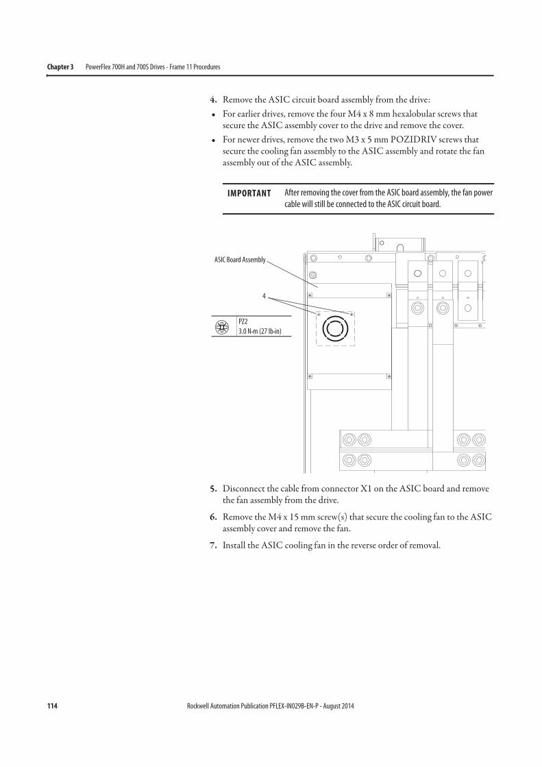
114 Rockwell Automation Publication PFLEX-IN029B-EN-P - August 2014
Chapter 3 PowerFlex 700H and 700S Drives - Frame 11 Procedures
4. Remove the ASIC circuit board assembly from the drive:• For earlier drives, remove the four M4 x 8 mm hexalobular screws that
secure the ASIC assembly cover to the drive and remove the cover.• For newer drives, remove the two M3 x 5 mm POZIDRIV screws that
secure the cooling fan assembly to the ASIC assembly and rotate the fan assembly out of the ASIC assembly.
5. Disconnect the cable from connector X1 on the ASIC board and remove the fan assembly from the drive.
6. Remove the M4 x 15 mm screw(s) that secure the cooling fan to the ASIC assembly cover and remove the fan.
7. Install the ASIC cooling fan in the reverse order of removal.
IMPORTANT After removing the cover from the ASIC board assembly, the fan power
cable will still be connected to the ASIC circuit board.
ASIC Board Assembly
4
PZ2
3.0 N•m (27 lb•in)
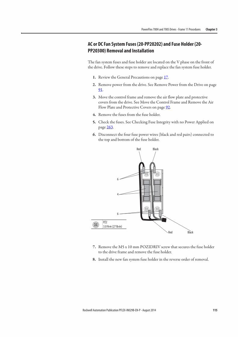
Rockwell Automation Publication PFLEX-IN029B-EN-P - August 2014 115
PowerFlex 700H and 700S Drives - Frame 11 Procedures Chapter 3
AC or DC Fan System Fuses (20-PP20202) and Fuse Holder (20-
PP20300) Removal and Installation
The fan system fuses and fuse holder are located on the V phase on the front of the drive. Follow these steps to remove and replace the fan system fuse holder.
1. Review the General Precautions on page 17.
2. Remove power from the drive. See Remove Power from the Drive on page 91.
3. Move the control frame and remove the air flow plate and protective covers from the drive. See Move the Control Frame and Remove the Air Flow Plate and Protective Covers on page 92.
4. Remove the fuses from the fuse holder.
5. Check the fuses. See Checking Fuse Integrity with no Power Applied on page 263.
6. Disconnect the four fuse power wires (black and red pairs) connected to the top and bottom of the fuse holder.
7. Remove the M5 x 10 mm POZIDRIV screw that secures the fuse holder to the drive frame and remove the fuse holder.
8. Install the new fan system fuse holder in the reverse order of removal.
6
6
BlackRed
BlackRed
PZ2
3.0 N•m (27 lb•in)
4

116 Rockwell Automation Publication PFLEX-IN029B-EN-P - August 2014
Chapter 3 PowerFlex 700H and 700S Drives - Frame 11 Procedures
Notes:
Rockwell Automation Publication PFLEX-IN029B-EN-P - August 2014 117
Chapter 4
PowerFlex 700H and 700S Drives - Frame 12 Procedures
This chapter contains spare part information and procedures for testing and replacing fan system components for frame 12 PowerFlex 700H and PowerFlex 700S drives. See Appendix A PowerFlex 700H and 700S Diagnostic Procedures on page 255 for additional component test procedures.
Frame 12 Fan System Spare Parts
Frame 12 PowerFlex 700H and PowerFlex 700S drives are essentially two parallel frame10 drives. Therefore, the spare parts are identical to the frame 10, with the exception that there are twice as many parts required. The procedures for replacing frame 12 fan system components are also the same as those for frame 10 drives.
The spare parts for frame 12 drives are contained in this chapter. See Chapter 2 - PowerFlex 700H and 700S Drives - Frame 10 Procedures on page 55 for detailed replacement procedures. See Frame 12 AC Fan System Wiring Schematic Diagram on page 119 and Frame 12 DC Fan System Wiring Schematic Diagram on page 120 for more information.
Topic Page
Frame 12 Fan System Spare Parts 117
Frame 12 Schematic Diagrams 119
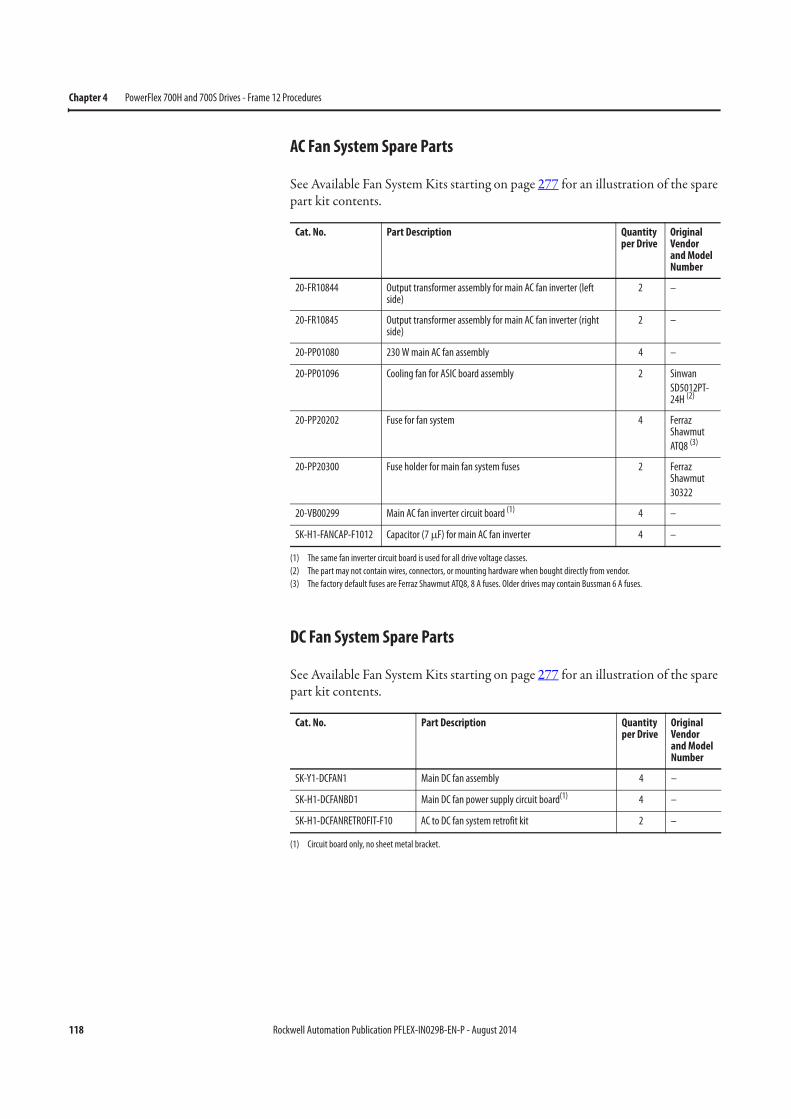
118 Rockwell Automation Publication PFLEX-IN029B-EN-P - August 2014
Chapter 4 PowerFlex 700H and 700S Drives - Frame 12 Procedures
AC Fan System Spare Parts
See Available Fan System Kits starting on page 277 for an illustration of the spare part kit contents.
DC Fan System Spare Parts
See Available Fan System Kits starting on page 277 for an illustration of the spare part kit contents.
Cat. No. Part Description Quantity per Drive
Original Vendor and Model Number
20-FR10844 Output transformer assembly for main AC fan inverter (left side)
2 –
20-FR10845 Output transformer assembly for main AC fan inverter (right side)
2 –
20-PP01080 230 W main AC fan assembly 4 –
20-PP01096 Cooling fan for ASIC board assembly 2 Sinwan
SD5012PT-24H (2)
(2) The part may not contain wires, connectors, or mounting hardware when bought directly from vendor.
20-PP20202 Fuse for fan system 4 Ferraz Shawmut
ATQ8 (3)
(3) The factory default fuses are Ferraz Shawmut ATQ8, 8 A fuses. Older drives may contain Bussman 6 A fuses.
20-PP20300 Fuse holder for main fan system fuses 2 Ferraz Shawmut
30322
20-VB00299 Main AC fan inverter circuit board (1)
(1) The same fan inverter circuit board is used for all drive voltage classes.
4 –
SK-H1-FANCAP-F1012 Capacitor (7 μF) for main AC fan inverter 4 –
Cat. No. Part Description Quantity per Drive
Original Vendor and Model Number
SK-Y1-DCFAN1 Main DC fan assembly 4 –
SK-H1-DCFANBD1 Main DC fan power supply circuit board(1)
(1) Circuit board only, no sheet metal bracket.
4 –
SK-H1-DCFANRETROFIT-F10 AC to DC fan system retrofit kit 2 –
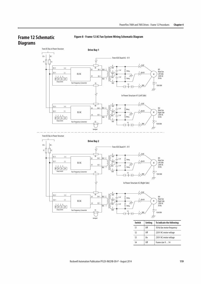
Rockwell Automation Publication PFLEX-IN029B-EN-P - August 2014 119
PowerFlex 700H and 700S Drives - Frame 12 Procedures Chapter 4
Frame 12 Schematic Diagrams
Figure 8 - Frame 12 AC Fan System Wiring Schematic Diagram
(+)
1 2 3 4
Off On
DC/AC
X8
F1
Setup SwitchX3
From ASIC Board #2 - X11
U1
V1
X4-1
X5-1
(-)X2-1
X2-3
X5-1
X4-1
X2-1
X2-3
V1
X3
(-)
(+) X8
U1
3
DC-DC+
4
Fan Frequency Converter
DC/AC
BLK
1
BLK 2
3
BLK
BLK 2.2uf4BLK5
2.2uf
7uf
10Meg
10Meg
6
BLK
BLK
1
BLK 2
3
BLK
BLK 2.2uf4BLK5
2.2uf
7uf
10Meg
10Meg
6
BLK
Jumper
2 4
F2
In Power Structure #1 (Left Side)
(+) X8
F1
X3
U1
V1
X4-1
X5-1
(-)X2-1
X2-3
X5-1
X4-1
X2-1
X2-3
V1
X3
(-)
(+) X8U1
3
DC-DC+
4
BLK
1
BLK 2
3BLK
BLK 2.2uf4BLK5
2.2uf
7uf
10Meg
10Meg
6
BLK
BLK
1
BLK 2
3BLK
BLK 2.2uf4BLK5
2.2uf
7uf
10Meg
6
BLK
2 4
F2
In Power Structure #2 (Right Side)
Fan Frequency Converter
From ASIC Board #1 - X11
DC/AC
DC/AC
Fan Frequency Converter
Fan Frequency Converter
Jumper
From DC Bus in Power Structure
From DC Bus in Power Structure
Off Off
1 2 3 4
Off On
Setup Switch
Off Off
1 2 3 4
Off On
Setup Switch
Off Off
1 2 3 4
Off On
Setup Switch
Off Off
1 BRN
M1Main FanLeft Side230V AC50 Hz
BLUE2
YLW/GRN
4
M2Main FanRight Side230V AC50 Hz
M
BLACK3
YLW/GRN
4
M
1 BRN
BLUE2
BLACK3
1 BRN
M3Main FanLeft Side230V AC50 Hz
BLUE2
YLW/GRN
4
M4Main FanRight Side230V AC50 Hz
M
BLACK3
YLW/GRN
4
M
1 BRN
BLUE2
BLACK3
10Meg
Switch Setting To indicate the following:
S1 Off 50 Hz fan motor frequency
S2 Off 220 V AC motor voltage
S3 On 230 V AC motor voltage
S4 Off Frame size 9…14
Drive Bay 1
Drive Bay 2
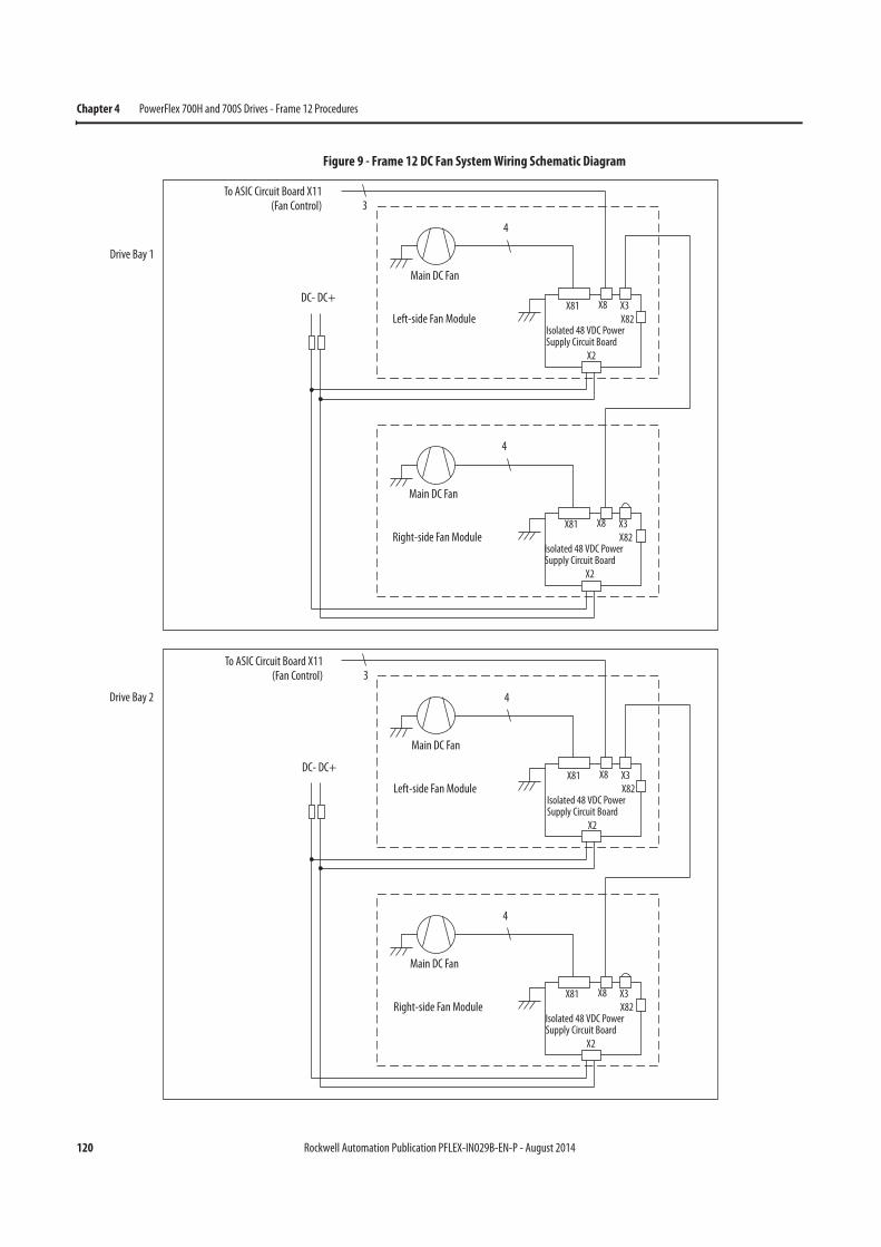
120 Rockwell Automation Publication PFLEX-IN029B-EN-P - August 2014
Chapter 4 PowerFlex 700H and 700S Drives - Frame 12 Procedures
Figure 9 - Frame 12 DC Fan System Wiring Schematic Diagram
3To ASIC Circuit Board X11
(Fan Control)
4
Main DC Fan
Left-side Fan Module
DC- DC+
Isolated 48 VDC Power Supply Circuit Board
X81 X8 X3
X82
X2
4
Main DC Fan
Right-side Fan ModuleIsolated 48 VDC Power Supply Circuit Board
X81 X8 X3
X82
X2
3To ASIC Circuit Board X11
(Fan Control)
4
Main DC Fan
Left-side Fan Module
DC- DC+
Isolated 48 VDC Power Supply Circuit Board
X81 X8 X3
X82
X2
4
Main DC Fan
Right-side Fan ModuleIsolated 48 VDC Power Supply Circuit Board
X81 X8 X3
X82
X2
Drive Bay 1
Drive Bay 2
Rockwell Automation Publication PFLEX-IN029B-EN-P - August 2014 121
Chapter 5
PowerFlex 700H and 700S Drives - Frame 13 Procedures
This chapter contains spare part information and procedures for testing and replacing fan system components for frame 13 PowerFlex 700H and PowerFlex 700S drives. See Appendix A PowerFlex 700H and 700S Diagnostic Procedures on page 255 for additional component test procedures.
Topic Page
Frame 13 Drive Configurations 122
Frame 13 Fan System Spare Parts 123
DC Fan Systems 124
Tools Needed for Frame 13 Fan System Repairs 125
Frame 13 AFE Schematic Diagrams 125
Frame 13 Fan System Replacement Procedures 134
Remove Power from the Drive 134
Move the Control Frame, and Remove the Screens, Airflow Plates, and Protective Covers 135
Remove the Voltage Feedback Circuit Board Assembly (Inverter Only) 138
ASIC Circuit Board Assembly Cooling Fan (20-PP01096) Removal and Installation (Inverter Only) 139
AC or DC Fan System Fuses (20-PP20202) and Fuse Holder (20-PP20300) Removal and Installation 141
Remove the Main Fan Assembly 143
Removing the Main AC or DC Fan Power Supply Assemblies (Inverter Only) 145
Main AC Fan Inverter Circuit Board (20-VB00299) and DC Fan Power Supply Circuit Board (SK-H1-DCFANBD1) Removal and Installation (Converter Only)
148
Main AC Fan Inverter Circuit Board (20-VB00299) Removal and Installation (Inverter Only) 151
Main AC Fan Inverter Circuit Board (20-VB00299) and DC Fan Power Supply Circuit Board (SK-H1-DCFANBD1) Removal and Installation (Converter Only)
148
Main DC Fan Power Supply Circuit Board (SK-H1-DCFANBD1) Removal and Installation (Inverter Only) 153
AC to DC Main Fan System (SK-x1-DCFANRETROFIT-F13x and -14x) Retrofit 154
Main AC Fan Inverter Capacitor (SK-H1-FANCAP-F1314) Removal and Installation (Converter Only) 169
Main AC Fan Inverter Capacitor (SK-H1-FANCAP-F1314) Removal and Installation (Inverter Only) 170
Main AC Fan (20-FI13300) and Main DC Fan (SK-Y1-DCFAN1) Assembly Removal and Installation 174
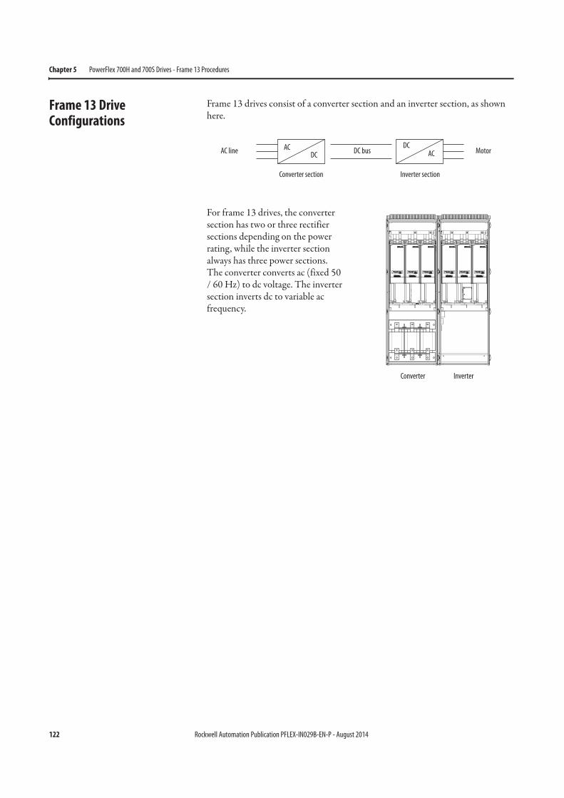
122 Rockwell Automation Publication PFLEX-IN029B-EN-P - August 2014
Chapter 5 PowerFlex 700H and 700S Drives - Frame 13 Procedures
Frame 13 Drive Configurations
Frame 13 drives consist of a converter section and an inverter section, as shown here.
For frame 13 drives, the converter section has two or three rectifier sections depending on the power rating, while the inverter section always has three power sections. The converter converts ac (fixed 50 / 60 Hz) to dc voltage. The inverter section inverts dc to variable ac frequency.
AC line ACDC
DCACDC bus Motor
Converter section Inverter section
Converter Inverter
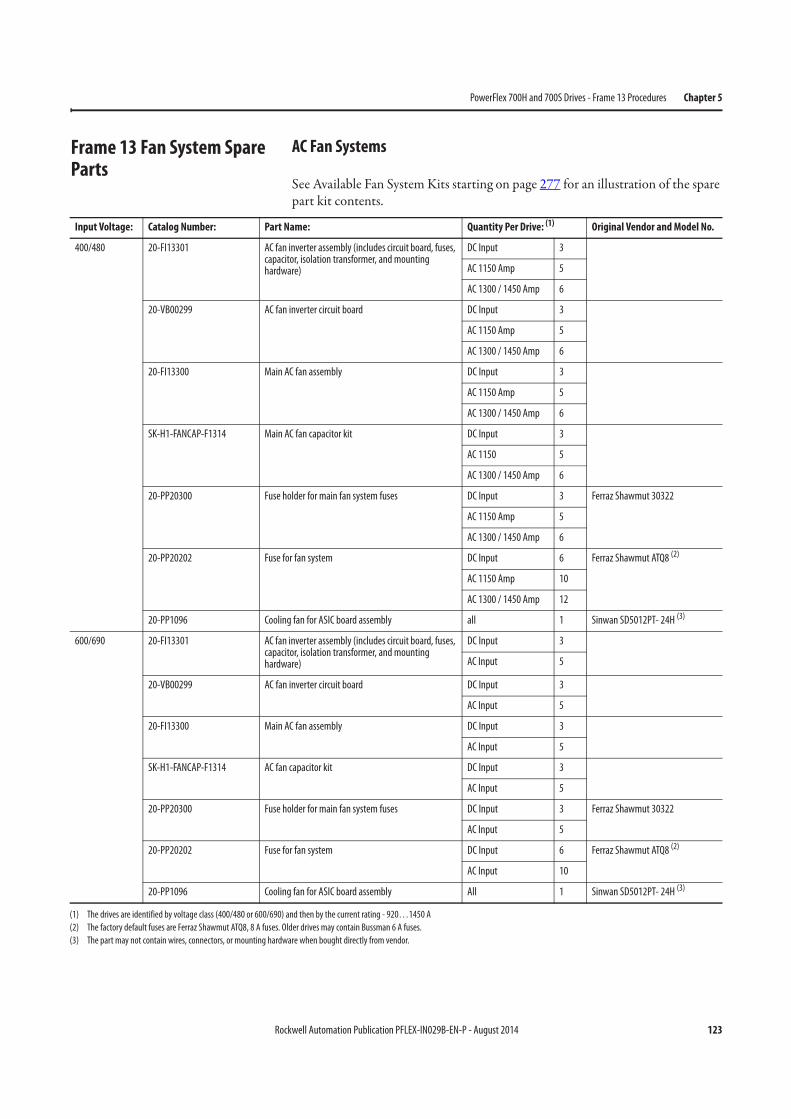
Rockwell Automation Publication PFLEX-IN029B-EN-P - August 2014 123
PowerFlex 700H and 700S Drives - Frame 13 Procedures Chapter 5
Frame 13 Fan System Spare Parts
AC Fan Systems
See Available Fan System Kits starting on page 277 for an illustration of the spare part kit contents.
Input Voltage: Catalog Number: Part Name: Quantity Per Drive: (1) Original Vendor and Model No.
400/480 20-FI13301 AC fan inverter assembly (includes circuit board, fuses, capacitor, isolation transformer, and mounting hardware)
DC Input 3
AC 1150 Amp 5
AC 1300 / 1450 Amp 6
20-VB00299 AC fan inverter circuit board DC Input 3
AC 1150 Amp 5
AC 1300 / 1450 Amp 6
20-FI13300 Main AC fan assembly DC Input 3
AC 1150 Amp 5
AC 1300 / 1450 Amp 6
SK-H1-FANCAP-F1314 Main AC fan capacitor kit DC Input 3
AC 1150 5
AC 1300 / 1450 Amp 6
20-PP20300 Fuse holder for main fan system fuses DC Input 3 Ferraz Shawmut 30322
AC 1150 Amp 5
AC 1300 / 1450 Amp 6
20-PP20202 Fuse for fan system DC Input 6 Ferraz Shawmut ATQ8 (2)
AC 1150 Amp 10
AC 1300 / 1450 Amp 12
20-PP1096 Cooling fan for ASIC board assembly all 1 Sinwan SD5012PT- 24H (3)
600/690 20-FI13301 AC fan inverter assembly (includes circuit board, fuses, capacitor, isolation transformer, and mounting hardware)
DC Input 3
AC Input 5
20-VB00299 AC fan inverter circuit board DC Input 3
AC Input 5
20-FI13300 Main AC fan assembly DC Input 3
AC Input 5
SK-H1-FANCAP-F1314 AC fan capacitor kit DC Input 3
AC Input 5
20-PP20300 Fuse holder for main fan system fuses DC Input 3 Ferraz Shawmut 30322
AC Input 5
20-PP20202 Fuse for fan system DC Input 6 Ferraz Shawmut ATQ8 (2)
AC Input 10
20-PP1096 Cooling fan for ASIC board assembly All 1 Sinwan SD5012PT- 24H (3)
(1) The drives are identified by voltage class (400/480 or 600/690) and then by the current rating - 920…1450 A
(2) The factory default fuses are Ferraz Shawmut ATQ8, 8 A fuses. Older drives may contain Bussman 6 A fuses.
(3) The part may not contain wires, connectors, or mounting hardware when bought directly from vendor.
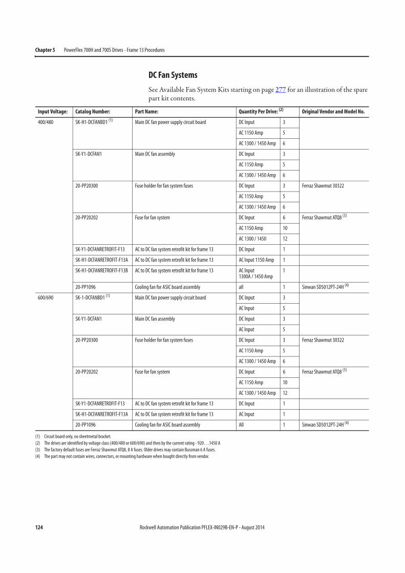
124 Rockwell Automation Publication PFLEX-IN029B-EN-P - August 2014
Chapter 5 PowerFlex 700H and 700S Drives - Frame 13 Procedures
DC Fan Systems
See Available Fan System Kits starting on page 277 for an illustration of the spare part kit contents.
Input Voltage: Catalog Number: Part Name: Quantity Per Drive: (2) Original Vendor and Model No.
400/480 SK-H1-DCFANBD1 (1) Main DC fan power supply circuit board DC Input 3
AC 1150 Amp 5
AC 1300 / 1450 Amp 6
SK-Y1-DCFAN1 Main DC fan assembly DC Input 3
AC 1150 Amp 5
AC 1300 / 1450 Amp 6
20-PP20300 Fuse holder for fan system fuses DC Input 3 Ferraz Shawmut 30322
AC 1150 Amp 5
AC 1300 / 1450 Amp 6
20-PP20202 Fuse for fan system DC Input 6 Ferraz Shawmut ATQ8 (3)
AC 1150 Amp 10
AC 1300 / 1450 12
SK-Y1-DCFANRETROFIT-F13 AC to DC fan system retrofit kit for frame 13 DC Input 1
SK-H1-DCFANRETROFIT-F13A AC to DC fan system retrofit kit for frame 13 AC Input 1150 Amp 1
SK-H1-DCFANRETROFIT-F13B AC to DC fan system retrofit kit for frame 13 AC Input1300A / 1450 Amp
1
20-PP1096 Cooling fan for ASIC board assembly all 1 Sinwan SD5012PT-24H (4)
600/690 SK-1-DCFANBD1 (1) Main DC fan power supply circuit board DC Input 3
AC Input 5
SK-Y1-DCFAN1 Main DC fan assembly DC Input 3
AC Input 5
20-PP20300 Fuse holder for fan system fuses DC Input 3 Ferraz Shawmut 30322
AC 1150 Amp 5
AC 1300 / 1450 Amp 6
20-PP20202 Fuse for fan system DC Input 6 Ferraz Shawmut ATQ8 (3)
AC 1150 Amp 10
AC 1300 / 1450 Amp 12
SK-Y1-DCFANRETROFIT-F13 AC to DC fan system retrofit kit for frame 13 DC Input 1
SK-H1-DCFANRETROFIT-F13A AC to DC fan system retrofit kit for frame 13 AC Input 1
20-PP1096 Cooling fan for ASIC board assembly All 1 Sinwan SD5012PT-24H (4)
(1) Circuit board only, no sheetmetal bracket.
(2) The drives are identified by voltage class (400/480 or 600/690) and then by the current rating - 920…1450 A
(3) The factory default fuses are Ferraz Shawmut ATQ8, 8 A fuses. Older drives may contain Bussman 6 A fuses.
(4) The part may not contain wires, connectors, or mounting hardware when bought directly from vendor.

Rockwell Automation Publication PFLEX-IN029B-EN-P - August 2014 125
PowerFlex 700H and 700S Drives - Frame 13 Procedures Chapter 5
Tools Needed for Frame 13 Fan System Repairs
• #2 POZIDRIV screwdriver• 19 mm socket wrench• 5.5 mm hex key or HOP6 bit• T20 and T25 hexalobular screwdriver• Multi meter• Fuse puller• Needle-nose pliers• Wire cutter• Cable ties• Optional: PowerFlex 700H and 700S maintenance stand (cat. No. 20-
MAINSTND)
Frame 13 AFE Schematic Diagrams
The PowerFlex 700H and PowerFlex 700S frame 13 drive can be configured with either AC or DC (common bus) input voltage applied. The AC input drives have both converter and inverter sections, while the DC input drives have only an inverter. The schematics will change based on this hardware configuration. Table 2 provides a list of schematic diagrams applicable to each drive configuration.
Table 2 - Drive Configurations and Applicable Schematics
Drive Input Voltage Drive Hardware Section AC Fan Systems DC Fan Systems
AC System Figure 10 on page 126
Converter Figure 11 on page 127 Figure 12 on page 128
Inverter Figure 13 on page 129 Figure 14 on page 130
DC System Figure 15 on page 131
Converter n/a n/a
Inverter Figure 16 on page 132 Figure 17 on page 133
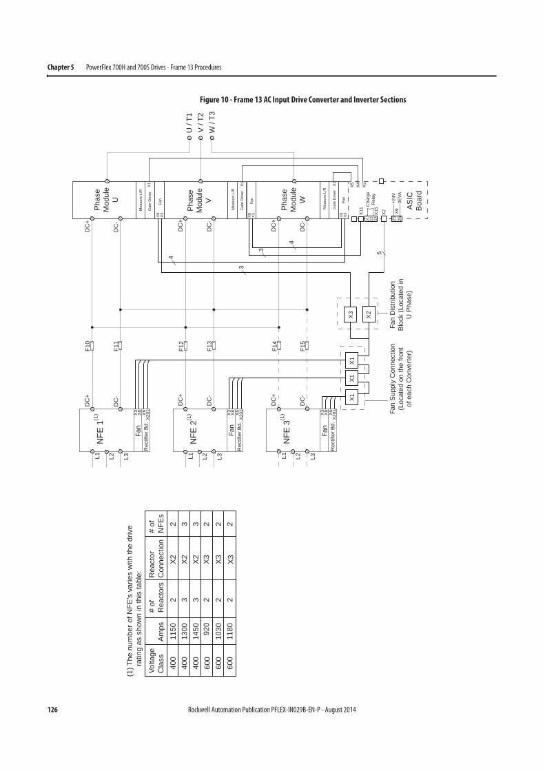
126 Rockwell Automation Publication PFLEX-IN029B-EN-P - August 2014
Chapter 5 PowerFlex 700H and 700S Drives - Frame 13 Procedures
Figure 10 - Frame 13 AC Input Drive Converter and Inverter Sections
Fan
Rec
tifie
r Bd.
L1 L3L2
NFE
3(1
) X3
X8
X6
X20
1
Fan
Rec
tifie
r Bd.
L1 L3L2
NFE
2(1
) X3
X8
X6
X20
1
Fan
Rec
tifie
r Bd.
L1 L3L2
NFE
1(1
) X3
X8
X6
X20
1
F10
F11
DC
+
DC
- X1
X1
X1
Fan
Dis
tribu
tion
Blo
ck (L
ocat
ed in
U P
hase
)
F12
F13
DC
+
DC
-
DC
+
DC
-
F14
F15
5
25 2621 22 23
X9
+24V
0EVA
X15
Cha
rge
Rel
ay
X2
Fan
Gat
e D
river
Mea
sure
L/R
X5
X4
X3
X11
Fan
Gat
e D
river
Mea
sure
L/R
Fan
Gat
e D
river
Mea
sure
L/R
Pha
seM
odul
eW
Pha
seM
odul
eV
Pha
seM
odul
eU
X3
X8
X3
X8X3
X8
X1 X1 X1
4
3
3
4
U /
T1V
/ T2
W /
T3
AS
ICB
oard
(1) T
he n
umbe
r of N
FE’s
var
ies
with
the
driv
e
ratin
g as
sho
wn
in th
is ta
ble:
Volta
geC
lass
Am
ps#
ofR
eact
ors
Rea
ctor
Con
nect
ion
# of
NFE
s40
040
040
060
060
060
0
1150
1300
1450 92
010
3011
80
2 3 3 2 2 2
X2
X2
X2
X3
X3
X3
2 3 3 2 2 2
DC
+
DC
-
DC
+
DC
-
DC
+
DC
-
Fan
Sup
ply
Con
nect
ion
(Loc
ated
on
the
front
of e
ach
Con
verte
r)
X3
X2
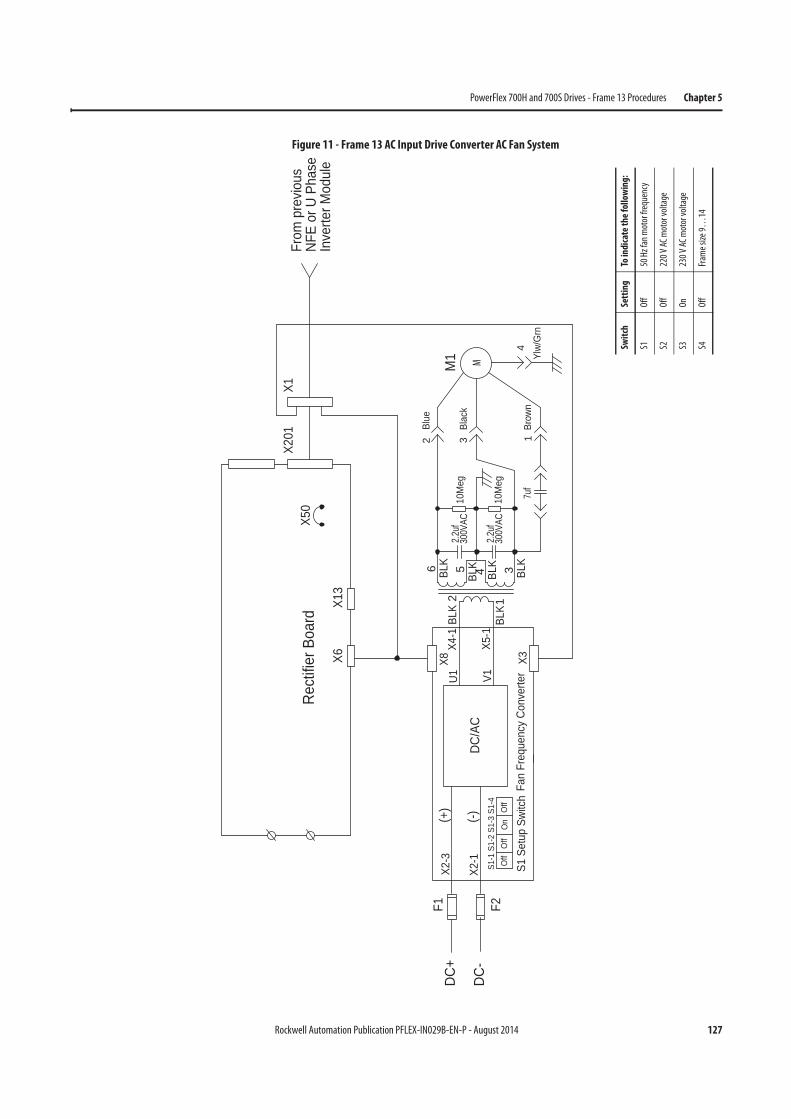
Rockwell Automation Publication PFLEX-IN029B-EN-P - August 2014 127
PowerFlex 700H and 700S Drives - Frame 13 Procedures Chapter 5
Figure 11 - Frame 13 AC Input Drive Converter AC Fan System
Rect
ifier B
oard
X201
X6X1
3
X50
X1
(+)
DC/A
C
X8F1
X3
U1 V1
X4-1
X5-1
(-)X2
-1
X2-3
BLK
300V
AC
300V
AC1
BLK
2
3 BLK
BLK
2.2u
f4BL
K52.
2uf
17u
fBr
own
10M
eg
10M
egBl
ack
3
Ylw/
Grn
4
M1
6Bl
ue2
BLK
F2S1
-1 S
1-2
S1-3
S1-
4 O
ffO
n
S1 S
etup
Swi
tch
Off
Off
Fan
Freq
uenc
y Co
nver
ter
From
pre
vious
NFE
or U
Pha
seIn
verte
r Mod
ule
MDC
-
DC+
Swit
chSe
ttin
gTo
indi
cate
th
e fo
llow
ing:
S1O
ff50
Hz
fan
mot
or fr
eque
ncy
S2O
ff22
0 V
AC m
otor
vol
tage
S3O
n23
0 V
AC m
otor
vol
tage
S4O
ffFr
ame
size
9…
14
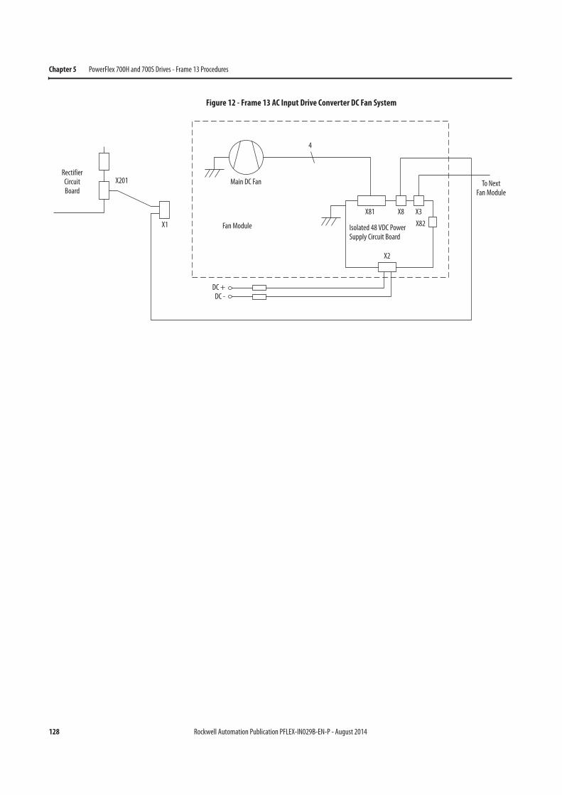
128 Rockwell Automation Publication PFLEX-IN029B-EN-P - August 2014
Chapter 5 PowerFlex 700H and 700S Drives - Frame 13 Procedures
Figure 12 - Frame 13 AC Input Drive Converter DC Fan System
RectifierCircuitBoard
X201
4
Main DC Fan
Fan Module
DC +DC -
Isolated 48 VDC Power Supply Circuit Board
X81 X8 X3
X82
X2
X1
To NextFan Module
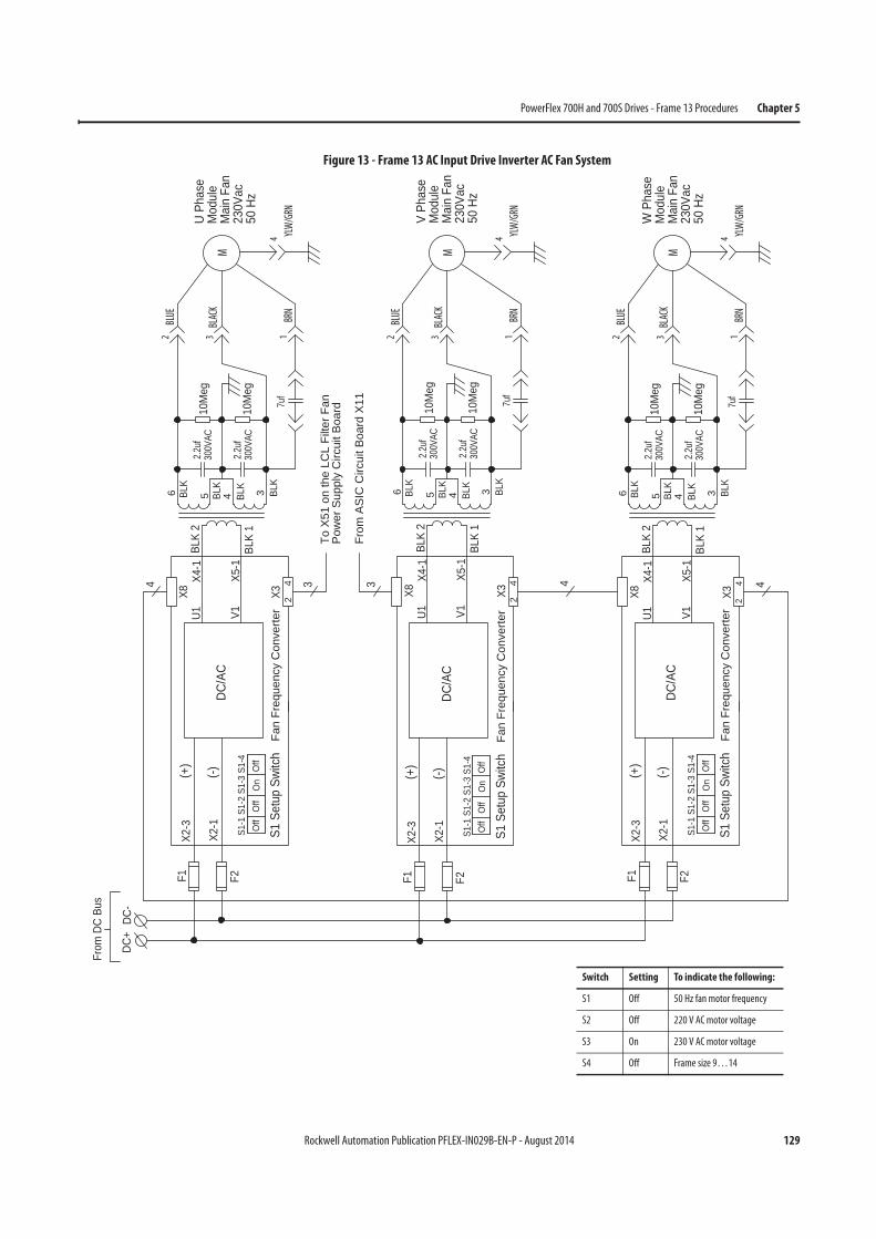
Rockwell Automation Publication PFLEX-IN029B-EN-P - August 2014 129
PowerFlex 700H and 700S Drives - Frame 13 Procedures Chapter 5
Figure 13 - Frame 13 AC Input Drive Inverter AC Fan System
BLK
42
3
X2-3
X2-1
F1
DC-
DC+
Fan
Freq
uenc
y C
onve
rter
DC/A
C(-)(+
)
X3
V1U1X8
BLK
1X5
-1
BLK
2X4
-1
4
6
2.2u
f30
0VAC
3 BLK
2.2u
f30
0VAC
5 BLK
4BLK
7uf
10M
eg
10M
eg
F2
24
24
From
DC
Bus
S1-1
S1-
2 S1
-3 S
1-4
Off
On
S1 S
etup
Swi
tch
Off
Off
U Ph
ase
Mod
ule
Mai
n Fa
n23
0Vac
50 H
z
V Ph
ase
Mod
ule
Mai
n Fa
n23
0Vac
50 H
z
W P
hase
Mod
ule
Mai
n Fa
n23
0Vac
50 H
z
BLK
4
X3
V1U1X8
BLK
1X5
-1
BLK
2X4
-1
6
2.2u
f30
0VAC
3 BLK
2.2u
f30
0VAC
5 BLK
4BLK
7uf
10M
eg
10M
eg
BLK
4
X3
V1U1X8
BLK
1X5
-1
BLK
2X4
-1
6
2.2u
f30
0VAC
3 BLK
2.2u
f30
0VAC
5 BLK
4BLK
7uf
10M
eg
10M
eg
X2-3
X2-1
F1
Fan
Freq
uenc
y C
onve
rter
DC/A
C(-)(+
)
F2S1
-1 S
1-2
S1-3
S1-
4 O
ffO
n
S1 S
etup
Swi
tch
Off
Off
X2-3
X2-1
F1
Fan
Freq
uenc
y C
onve
rter
DC/A
C(-)(+
)
F2S1
-1 S
1-2
S1-3
S1-
4 O
ffO
n
S1 S
etup
Swi
tch
Off
Off
3
To X
51 o
n th
e LC
L Fi
lter F
anP
ower
Sup
ply
Circ
uit B
oard
From
AS
IC C
ircui
t Boa
rd X
11
1BRN
BLUE
2
BLACK
3
YLW/GRN
4
M
1BRN
BLUE
2
BLACK
3
YLW/GRN
4
M
1BRN
BLUE
2
BLACK
3
YLW/GRN
4
M
Switch Setting To indicate the following:
S1 Off 50 Hz fan motor frequency
S2 Off 220 V AC motor voltage
S3 On 230 V AC motor voltage
S4 Off Frame size 9…14
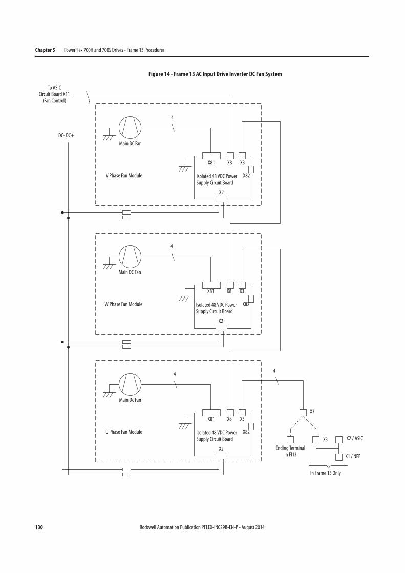
130 Rockwell Automation Publication PFLEX-IN029B-EN-P - August 2014
Chapter 5 PowerFlex 700H and 700S Drives - Frame 13 Procedures
Figure 14 - Frame 13 AC Input Drive Inverter DC Fan System
3
To ASICCircuit Board X11
(Fan Control)
4
Main DC Fan
V Phase Fan Module Isolated 48 VDC Power Supply Circuit Board
X81 X8 X3
X82
X2
4
Main DC Fan
W Phase Fan Module Isolated 48 VDC Power Supply Circuit Board
X81 X8 X3
X82
X2
4
Main Dc Fan
U Phase Fan Module Isolated 48 VDC Power Supply Circuit Board
X81 X8 X3
X82
X2
X3
4
X3 X2 / ASIC
X1 / NFE
Ending Terminal in FI13
In Frame 13 Only
DC- DC+
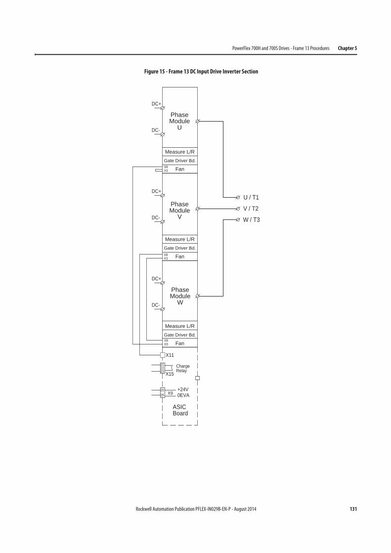
Rockwell Automation Publication PFLEX-IN029B-EN-P - August 2014 131
PowerFlex 700H and 700S Drives - Frame 13 Procedures Chapter 5
Figure 15 - Frame 13 DC Input Drive Inverter Section
X92625 +24V
0EVA
X15
212223
ChargeRelay
DC-
DC+
DC-
DC+
DC-
DC+
W / T3
U / T1
V / T2
X11
ASICBoard
Gate Driver Bd.
Fan
Measure L/R
PhaseModule
V
PhaseModule
U
PhaseModule
W
Gate Driver Bd.
Fan
Measure L/R
Gate Driver Bd.
Fan
Measure L/R
X8X3
X8X3
X8X3
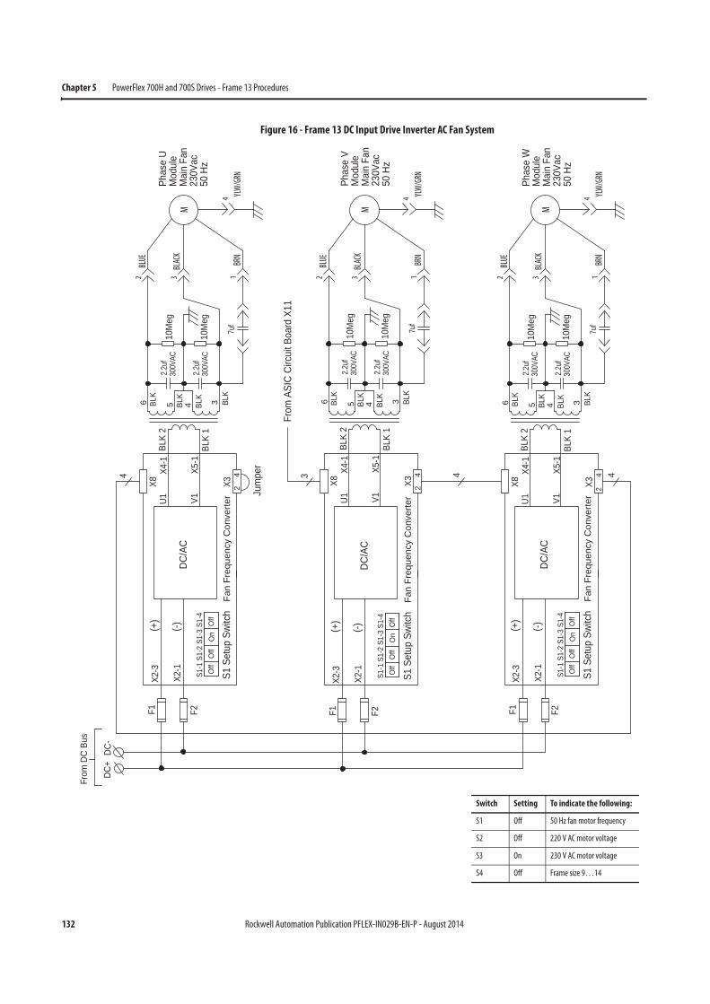
132 Rockwell Automation Publication PFLEX-IN029B-EN-P - August 2014
Chapter 5 PowerFlex 700H and 700S Drives - Frame 13 Procedures
Figure 16 - Frame 13 DC Input Drive Inverter AC Fan System
BLK
42
3
X2-3
X2-1
F1
DC-
DC+
Fan
Freq
uenc
y C
onve
rter
DC/A
C(-)(+
)
X3
V1U1X8
BLK
1X5
-1
BLK
2X4
-1
4
6
2.2u
f30
0VAC
3 BLK
2.2u
f30
0VAC
5 BLK
4BLK
7uf
10M
eg
10M
eg
F2
24
Jum
per
24
From
DC
Bus
S1-1
S1-
2 S1
-3 S
1-4
Off
On
S1 S
etup
Swi
tch
Off
Off
Phas
e U
Mod
ule
Mai
n Fa
n23
0Vac
50 H
z
Phas
e V
Mod
ule
Mai
n Fa
n23
0Vac
50 H
z
Phas
e W
Mod
ule
Mai
n Fa
n23
0Vac
50 H
z
BLK
4
X3
V1U1X8
BLK
1X5
-1
BLK
2X4
-1
6
2.2u
f30
0VAC
3 BLK
2.2u
f30
0VAC
5 BLK
4BLK
7uf
10M
eg
10M
eg
BLK
X3
V1U1X8
BLK
1X5
-1
BLK
2X4
-1
6
2.2u
f30
0VAC
3 BLK
2.2u
f30
0VAC
5 BLK
4BLK
7uf
10M
eg
10M
eg
X2-3
X2-1
F1
Fan
Freq
uenc
y C
onve
rter
DC/A
C(-)(+
)
F2S1
-1 S
1-2
S1-3
S1-
4 O
ffO
n
S1 S
etup
Swi
tch
Off
Off
X2-3
X2-1
F1
Fan
Freq
uenc
y C
onve
rter
DC/A
C(-)(+
)
F2S1
-1 S
1-2
S1-3
S1-
4 O
ffO
n
S1 S
etup
Swi
tch
Off
Off
From
ASI
C Ci
rcui
t Boa
rd X
11
4
1BRN
BLUE
2
BLACK
3
YLW/GRN
4
M
1BRN
BLUE
2
BLACK
3
YLW/GRN
4
M
1BRN
BLUE
2
BLACK
3
YLW/GRN
4
M
Switch Setting To indicate the following:
S1 Off 50 Hz fan motor frequency
S2 Off 220 V AC motor voltage
S3 On 230 V AC motor voltage
S4 Off Frame size 9…14
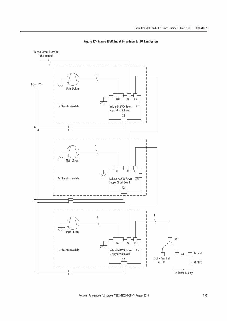
Rockwell Automation Publication PFLEX-IN029B-EN-P - August 2014 133
PowerFlex 700H and 700S Drives - Frame 13 Procedures Chapter 5
Figure 17 - Frame 13 AC Input Drive Inverter DC Fan System
3
To ASIC Circuit Board X11(Fan Control)
4
Main DC Fan
V Phase Fan Module
DC+
Isolated 48 VDC Power Supply Circuit Board
X81 X8 X3
X82
X2
4
Main DC Fan
W Phase Fan Module Isolated 48 VDC Power Supply Circuit Board
X81 X8 X3
X82
X2
4
Main DC Fan
U Phase Fan Module Isolated 48 VDC Power Supply Circuit Board
X81 X8 X3
X82
X2
DC–
X3
X3
Ending Terminal in FI13
In Frame 13 Only
X2 / ASIC
X1 / NFE
4
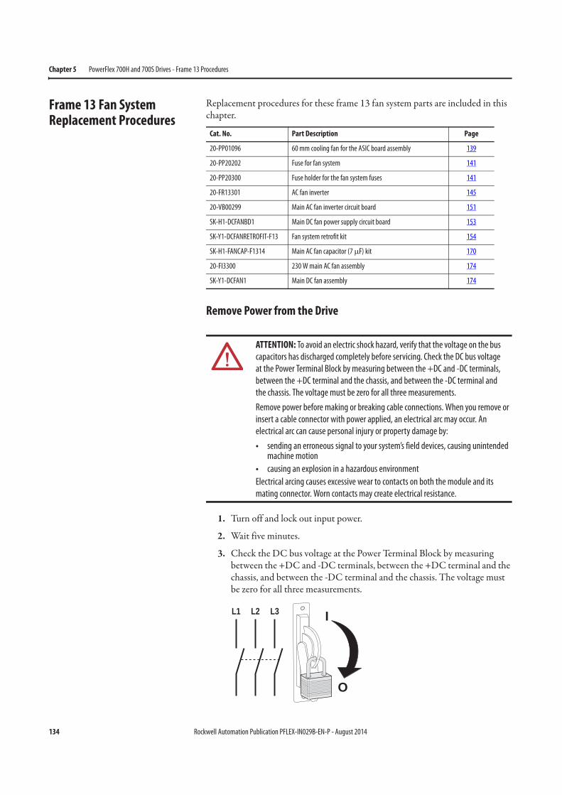
134 Rockwell Automation Publication PFLEX-IN029B-EN-P - August 2014
Chapter 5 PowerFlex 700H and 700S Drives - Frame 13 Procedures
Frame 13 Fan System Replacement Procedures
Replacement procedures for these frame 13 fan system parts are included in this chapter.
Remove Power from the Drive
1. Turn off and lock out input power.
2. Wait five minutes.
3. Check the DC bus voltage at the Power Terminal Block by measuring between the +DC and -DC terminals, between the +DC terminal and the chassis, and between the -DC terminal and the chassis. The voltage must be zero for all three measurements.
Cat. No. Part Description Page
20-PP01096 60 mm cooling fan for the ASIC board assembly 139
20-PP20202 Fuse for fan system 141
20-PP20300 Fuse holder for the fan system fuses 141
20-FR13301 AC fan inverter 145
20-VB00299 Main AC fan inverter circuit board 151
SK-H1-DCFANBD1 Main DC fan power supply circuit board 153
SK-Y1-DCFANRETROFIT-F13 Fan system retrofit kit 154
SK-H1-FANCAP-F1314 Main AC fan capacitor (7 μF) kit 170
20-FI3300 230 W main AC fan assembly 174
SK-Y1-DCFAN1 Main DC fan assembly 174
ATTENTION: To avoid an electric shock hazard, verify that the voltage on the bus
capacitors has discharged completely before servicing. Check the DC bus voltage
at the Power Terminal Block by measuring between the +DC and -DC terminals,
between the +DC terminal and the chassis, and between the -DC terminal and
the chassis. The voltage must be zero for all three measurements.
Remove power before making or breaking cable connections. When you remove or
insert a cable connector with power applied, an electrical arc may occur. An
electrical arc can cause personal injury or property damage by:
• sending an erroneous signal to your system’s field devices, causing unintended machine motion
• causing an explosion in a hazardous environment
Electrical arcing causes excessive wear to contacts on both the module and its
mating connector. Worn contacts may create electrical resistance.
L1 L2 L3
O
I

Rockwell Automation Publication PFLEX-IN029B-EN-P - August 2014 135
PowerFlex 700H and 700S Drives - Frame 13 Procedures Chapter 5
Move the Control Frame, and Remove the Screens, Airflow Plates,
and Protective Covers
You may need to move the control frame based on the mounting location. You must remove the screens, air flow plate and protective covers from the drive in order to access fan system components on the drive power structure. Follow these steps to move the control frame and remove the screens, airflow plate and protective covers.
1. Review the General Precautions on page 17.
2. Remove power from the drive. See Remove Power from the Drive on page 134.
3. If moving the control frame from a DC input drive with pre-charge interlock, disconnect the wiring from terminal strip X50.
4. Loosen the two hexalobular screws that secure the control frame to the enclosure and swing the control frame away from the drive.
T20
3.0 N•m (27 lb•in)
4
3
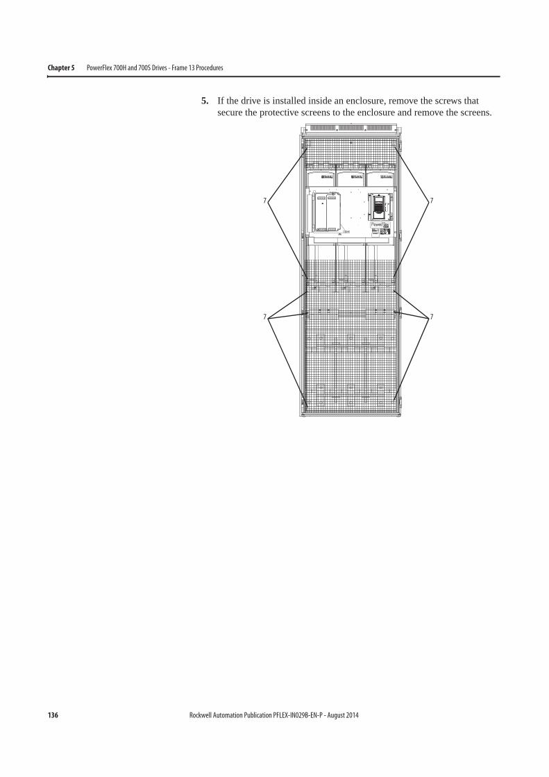
136 Rockwell Automation Publication PFLEX-IN029B-EN-P - August 2014
Chapter 5 PowerFlex 700H and 700S Drives - Frame 13 Procedures
5. If the drive is installed inside an enclosure, remove the screws that secure the protective screens to the enclosure and remove the screens.
7
7 7
7
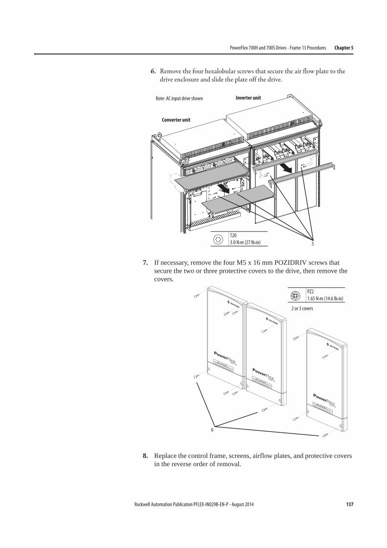
Rockwell Automation Publication PFLEX-IN029B-EN-P - August 2014 137
PowerFlex 700H and 700S Drives - Frame 13 Procedures Chapter 5
6. Remove the four hexalobular screws that secure the air flow plate to the drive enclosure and slide the plate off the drive.
7. If necessary, remove the four M5 x 16 mm POZIDRIV screws that secure the two or three protective covers to the drive, then remove the covers.
8. Replace the control frame, screens, airflow plates, and protective covers in the reverse order of removal.
5
Converter unit
Inverter unitNote: AC input drive shown
T20
3.0 N•m (27 lb•in)
DC BUS CONDUCTORS AND CAPACITORS
OPERATE AT HIGH VOLTAGE. REMOVE POWER
AND WAIT 5 MINUTES BEFORE SERVICING
DANGER
!
DC BUS CONDUCTORS AND CAPACITORS
OPERATE AT HIGH VOLTAGE. REMOVE POWER
AND WAIT 5 MINUTES BEFORE SERVICING
DANGER
!
DC BUS CONDUCTORS AND CAPACITORS
OPERATE AT HIGH VOLTAGE. REMOVE POWER
AND WAIT 5 MINUTES BEFORE SERVICING
DANGER
!
2 or 3 covers
6
PZ2
1.65 N•m (14.6 lb•in)
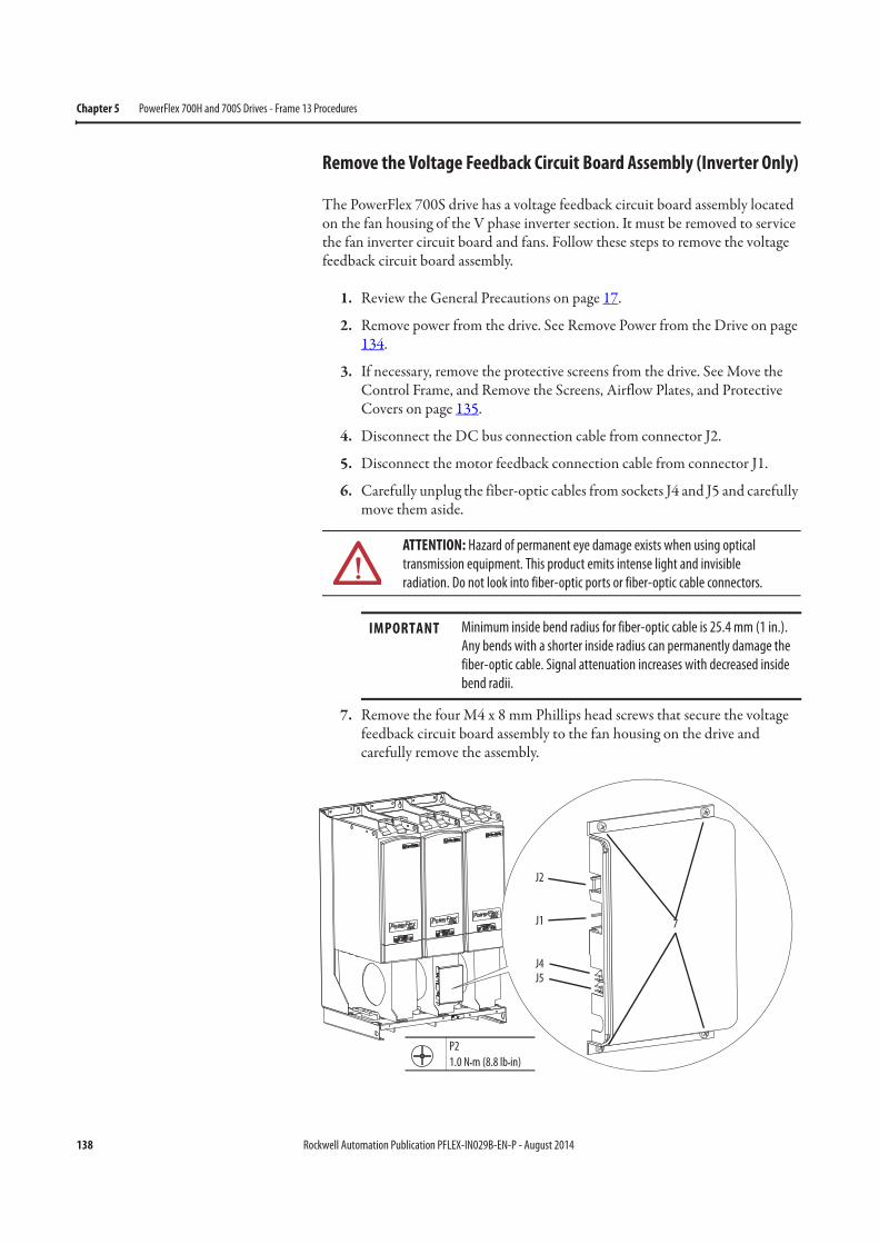
138 Rockwell Automation Publication PFLEX-IN029B-EN-P - August 2014
Chapter 5 PowerFlex 700H and 700S Drives - Frame 13 Procedures
Remove the Voltage Feedback Circuit Board Assembly (Inverter Only)
The PowerFlex 700S drive has a voltage feedback circuit board assembly located on the fan housing of the V phase inverter section. It must be removed to service the fan inverter circuit board and fans. Follow these steps to remove the voltage feedback circuit board assembly.
1. Review the General Precautions on page 17.
2. Remove power from the drive. See Remove Power from the Drive on page 134.
3. If necessary, remove the protective screens from the drive. See Move the Control Frame, and Remove the Screens, Airflow Plates, and Protective Covers on page 135.
4. Disconnect the DC bus connection cable from connector J2.
5. Disconnect the motor feedback connection cable from connector J1.
6. Carefully unplug the fiber-optic cables from sockets J4 and J5 and carefully move them aside.
7. Remove the four M4 x 8 mm Phillips head screws that secure the voltage feedback circuit board assembly to the fan housing on the drive and carefully remove the assembly.
ATTENTION: Hazard of permanent eye damage exists when using optical
transmission equipment. This product emits intense light and invisible
radiation. Do not look into fiber-optic ports or fiber-optic cable connectors.
IMPORTANT Minimum inside bend radius for fiber-optic cable is 25.4 mm (1 in.).
Any bends with a shorter inside radius can permanently damage the
fiber-optic cable. Signal attenuation increases with decreased inside
bend radii.
J2
J1
J4J5
7
P2
1.0 N•m (8.8 lb•in)
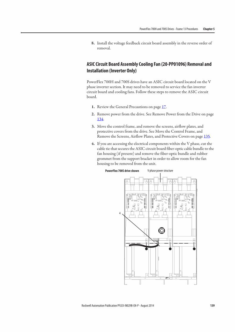
Rockwell Automation Publication PFLEX-IN029B-EN-P - August 2014 139
PowerFlex 700H and 700S Drives - Frame 13 Procedures Chapter 5
8. Install the voltage feedback circuit board assembly in the reverse order of removal.
ASIC Circuit Board Assembly Cooling Fan (20-PP01096) Removal and
Installation (Inverter Only)
PowerFlex 700H and 700S drives have an ASIC circuit board located on the V phase inverter section. It may need to be removed to service the fan inverter circuit board and cooling fans. Follow these steps to remove the ASIC circuit board.
1. Review the General Precautions on page 17.
2. Remove power from the drive. See Remove Power from the Drive on page 134.
3. Move the control frame, and remove the screens, airflow plates, and protective covers from the drive. See Move the Control Frame, and Remove the Screens, Airflow Plates, and Protective Covers on page 135.
4. If you are accessing the electrical components within the V phase, cut the cable tie that secures the ASIC circuit board fiber-optic cable bundle to the fan housing (if present) and remove the fiber-optic bundle and rubber grommet from the support bracket in order to allow room for the fan housing to be removed from the unit.
PowerFlex 700S drive shown
4
V phase power structure
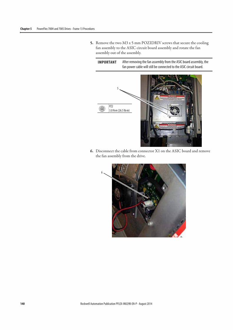
140 Rockwell Automation Publication PFLEX-IN029B-EN-P - August 2014
Chapter 5 PowerFlex 700H and 700S Drives - Frame 13 Procedures
5. Remove the two M3 x 5 mm POZIDRIV screws that secure the cooling fan assembly to the ASIC circuit board assembly and rotate the fan assembly out of the assembly.
6. Disconnect the cable from connector X1 on the ASIC board and remove the fan assembly from the drive.
IMPORTANT After removing the fan assembly from the ASIC board assembly, the
fan power cable will still be connected to the ASIC circuit board.
5
PZ2
3.0 N•m (26.5 lb•in)
6
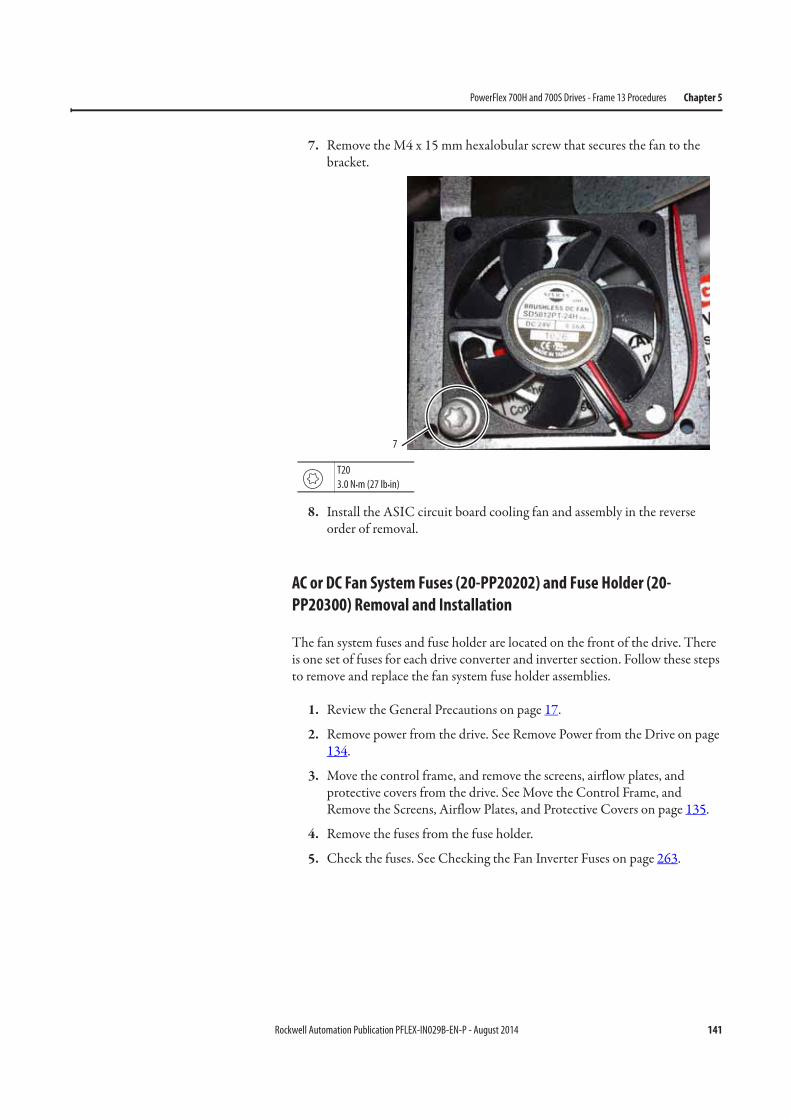
Rockwell Automation Publication PFLEX-IN029B-EN-P - August 2014 141
PowerFlex 700H and 700S Drives - Frame 13 Procedures Chapter 5
7. Remove the M4 x 15 mm hexalobular screw that secures the fan to the bracket.
8. Install the ASIC circuit board cooling fan and assembly in the reverse order of removal.
AC or DC Fan System Fuses (20-PP20202) and Fuse Holder (20-
PP20300) Removal and Installation
The fan system fuses and fuse holder are located on the front of the drive. There is one set of fuses for each drive converter and inverter section. Follow these steps to remove and replace the fan system fuse holder assemblies.
1. Review the General Precautions on page 17.
2. Remove power from the drive. See Remove Power from the Drive on page 134.
3. Move the control frame, and remove the screens, airflow plates, and protective covers from the drive. See Move the Control Frame, and Remove the Screens, Airflow Plates, and Protective Covers on page 135.
4. Remove the fuses from the fuse holder.
5. Check the fuses. See Checking the Fan Inverter Fuses on page 263.
7
T20
3.0 N•m (27 lb•in)
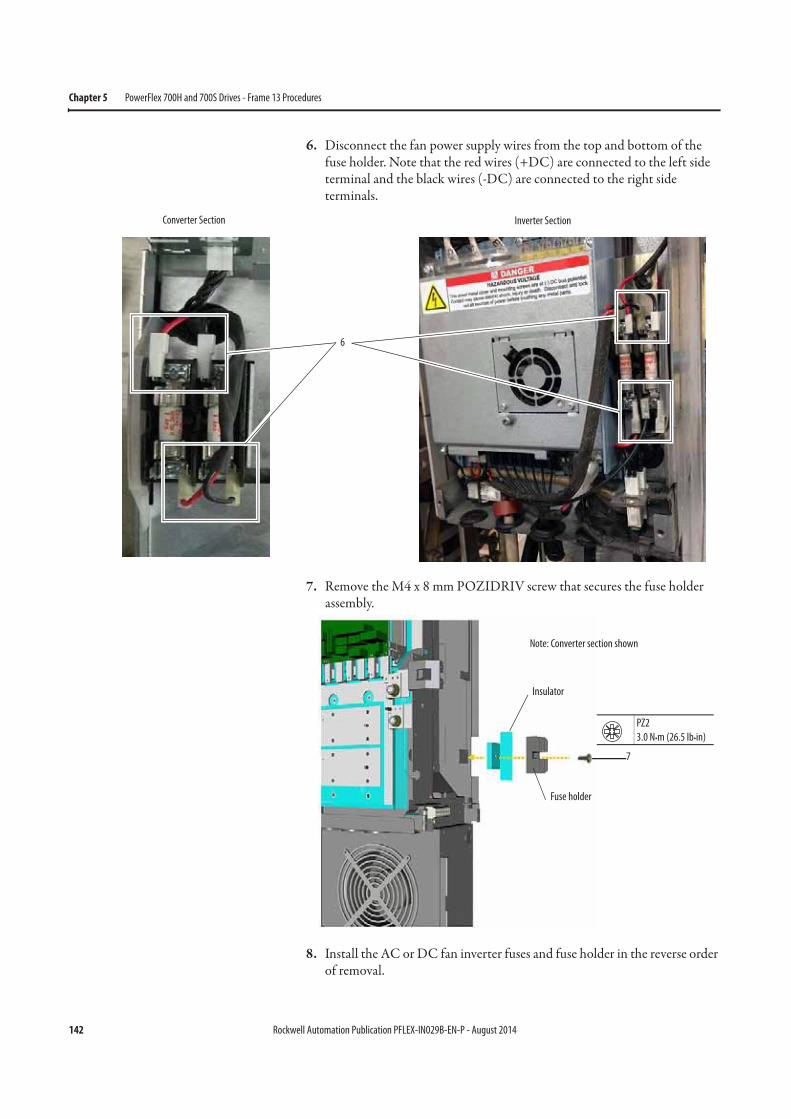
142 Rockwell Automation Publication PFLEX-IN029B-EN-P - August 2014
Chapter 5 PowerFlex 700H and 700S Drives - Frame 13 Procedures
6. Disconnect the fan power supply wires from the top and bottom of the fuse holder. Note that the red wires (+DC) are connected to the left side terminal and the black wires (-DC) are connected to the right side terminals.
7. Remove the M4 x 8 mm POZIDRIV screw that secures the fuse holder assembly.
8. Install the AC or DC fan inverter fuses and fuse holder in the reverse order of removal.
6
Converter Section Inverter Section
7
Insulator
Fuse holder
PZ2
3.0 N•m (26.5 lb•in)
Note: Converter section shown
Rockwell Automation Publication PFLEX-IN029B-EN-P - August 2014 143
PowerFlex 700H and 700S Drives - Frame 13 Procedures Chapter 5
Remove the Main Fan Assembly
The main fan assembly must be removed to gain access to the fan power supply circuit board. Follow these steps to remove the main fan assembly.
1. Review the General Precautions on page 17.
2. Remove power from the drive. See Remove Power from the Drive on page 134.
3. Move the control frame, and remove the screens, airflow plates, and protective covers from the drive. See Move the Control Frame, and Remove the Screens, Airflow Plates, and Protective Covers on page 135.
4. If necessary, remove the voltage feedback circuit board assembly. See Remove the Voltage Feedback Circuit Board Assembly (Inverter Only) on page 138.
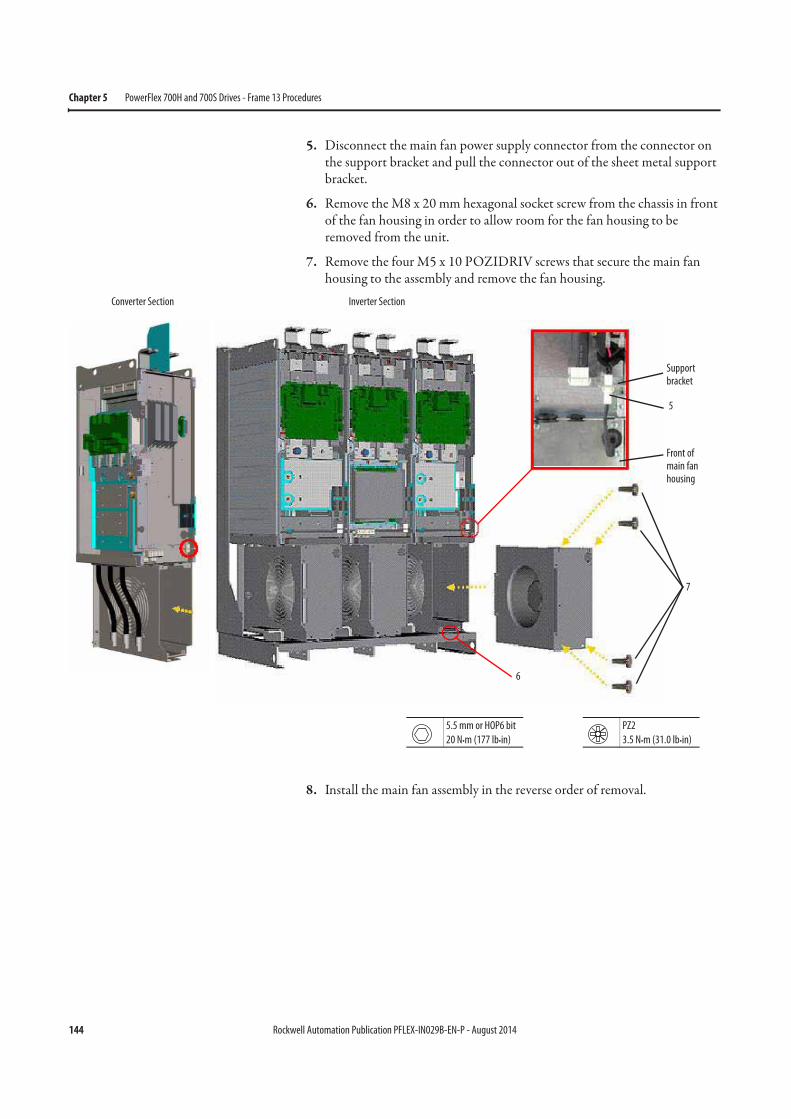
144 Rockwell Automation Publication PFLEX-IN029B-EN-P - August 2014
Chapter 5 PowerFlex 700H and 700S Drives - Frame 13 Procedures
5. Disconnect the main fan power supply connector from the connector on the support bracket and pull the connector out of the sheet metal support bracket.
6. Remove the M8 x 20 mm hexagonal socket screw from the chassis in front of the fan housing in order to allow room for the fan housing to be removed from the unit.
7. Remove the four M5 x 10 POZIDRIV screws that secure the main fan housing to the assembly and remove the fan housing.
8. Install the main fan assembly in the reverse order of removal.
5
7
6
5.5 mm or HOP6 bit
20 N•m (177 lb•in)
PZ2
3.5 N•m (31.0 lb•in)
Front of main fan housing
Support bracket
Inverter SectionConverter Section
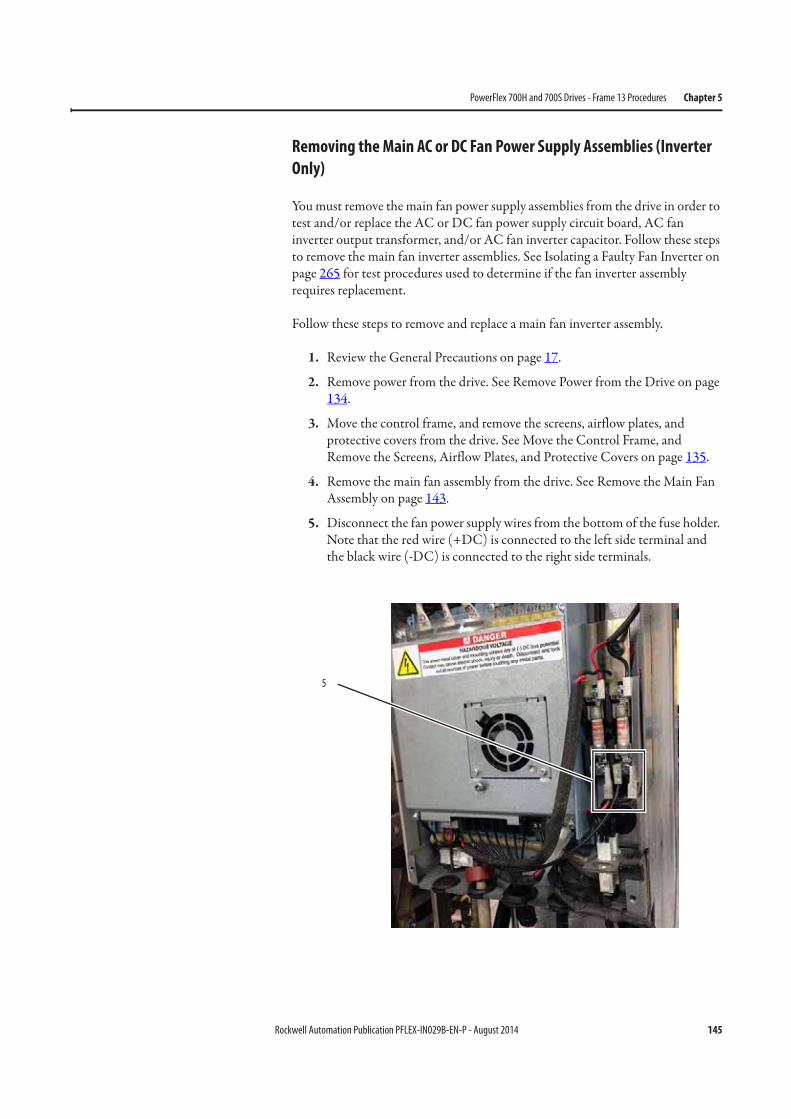
Rockwell Automation Publication PFLEX-IN029B-EN-P - August 2014 145
PowerFlex 700H and 700S Drives - Frame 13 Procedures Chapter 5
Removing the Main AC or DC Fan Power Supply Assemblies (Inverter
Only)
You must remove the main fan power supply assemblies from the drive in order to test and/or replace the AC or DC fan power supply circuit board, AC fan inverter output transformer, and/or AC fan inverter capacitor. Follow these steps to remove the main fan inverter assemblies. See Isolating a Faulty Fan Inverter on page 265 for test procedures used to determine if the fan inverter assembly requires replacement.
Follow these steps to remove and replace a main fan inverter assembly.
1. Review the General Precautions on page 17.
2. Remove power from the drive. See Remove Power from the Drive on page 134.
3. Move the control frame, and remove the screens, airflow plates, and protective covers from the drive. See Move the Control Frame, and Remove the Screens, Airflow Plates, and Protective Covers on page 135.
4. Remove the main fan assembly from the drive. See Remove the Main Fan Assembly on page 143.
5. Disconnect the fan power supply wires from the bottom of the fuse holder. Note that the red wire (+DC) is connected to the left side terminal and the black wire (-DC) is connected to the right side terminals.
5
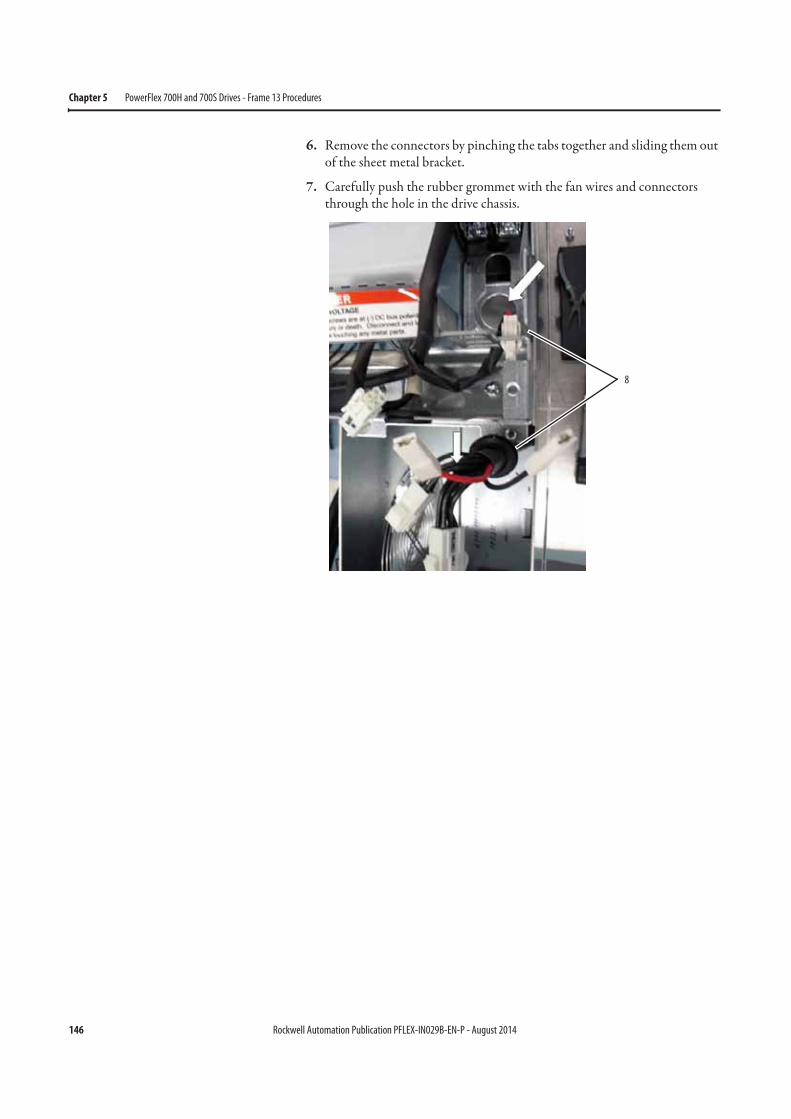
146 Rockwell Automation Publication PFLEX-IN029B-EN-P - August 2014
Chapter 5 PowerFlex 700H and 700S Drives - Frame 13 Procedures
6. Remove the connectors by pinching the tabs together and sliding them out of the sheet metal bracket.
7. Carefully push the rubber grommet with the fan wires and connectors through the hole in the drive chassis.
8
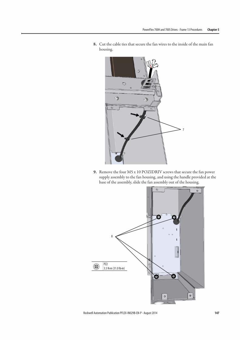
Rockwell Automation Publication PFLEX-IN029B-EN-P - August 2014 147
PowerFlex 700H and 700S Drives - Frame 13 Procedures Chapter 5
8. Cut the cable ties that secure the fan wires to the inside of the main fan housing.
9. Remove the four M5 x 10 POZIDRIV screws that secure the fan power supply assembly to the fan housing, and using the handle provided at the base of the assembly, slide the fan assembly out of the housing.
7
8
PZ2
3.5 N•m (31.0 lb•in)
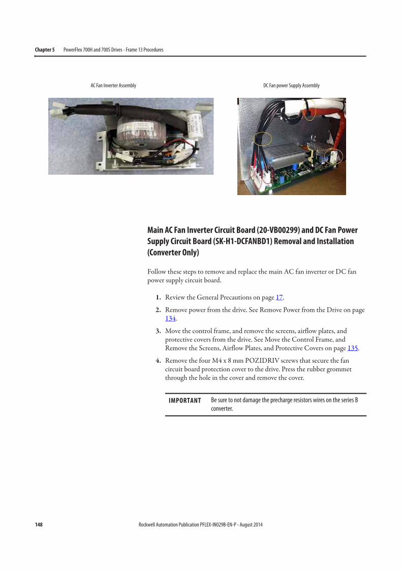
148 Rockwell Automation Publication PFLEX-IN029B-EN-P - August 2014
Chapter 5 PowerFlex 700H and 700S Drives - Frame 13 Procedures
Main AC Fan Inverter Circuit Board (20-VB00299) and DC Fan Power
Supply Circuit Board (SK-H1-DCFANBD1) Removal and Installation
(Converter Only)
Follow these steps to remove and replace the main AC fan inverter or DC fan power supply circuit board.
1. Review the General Precautions on page 17.
2. Remove power from the drive. See Remove Power from the Drive on page 134.
3. Move the control frame, and remove the screens, airflow plates, and protective covers from the drive. See Move the Control Frame, and Remove the Screens, Airflow Plates, and Protective Covers on page 135.
4. Remove the four M4 x 8 mm POZIDRIV screws that secure the fan circuit board protection cover to the drive. Press the rubber grommet through the hole in the cover and remove the cover.
AC Fan Inverter Assembly DC Fan power Supply Assembly
IMPORTANT Be sure to not damage the precharge resistors wires on the series B
converter.
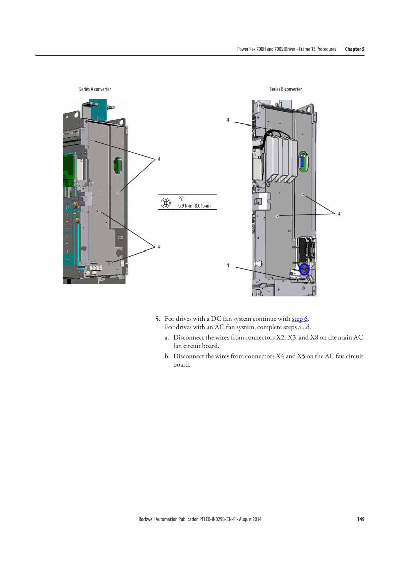
Rockwell Automation Publication PFLEX-IN029B-EN-P - August 2014 149
PowerFlex 700H and 700S Drives - Frame 13 Procedures Chapter 5
5. For drives with a DC fan system continue with step 6.For drives with an AC fan system, complete steps a…d.a. Disconnect the wires from connectors X2, X3, and X8 on the main AC
fan circuit board.b. Disconnect the wires from connectors X4 and X5 on the AC fan circuit
board.
4
4
PZ1
0.9 N•m (8.0 lb•in)
Series A converter
4
4
4
Series B converter
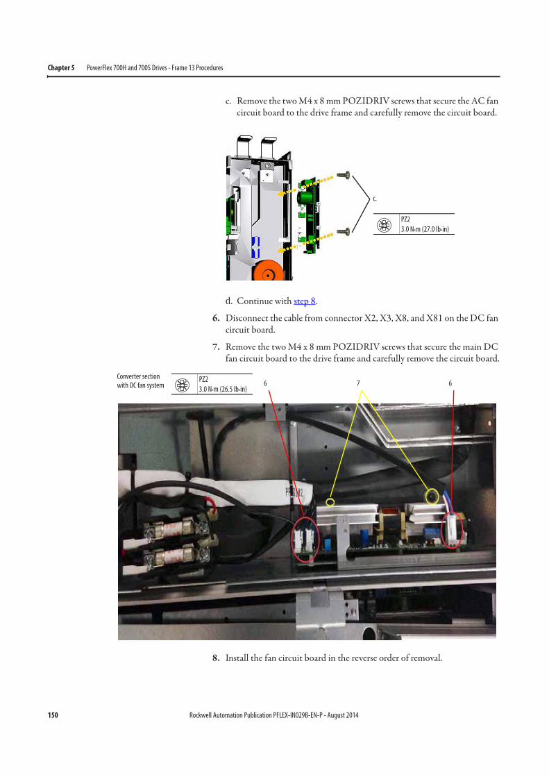
150 Rockwell Automation Publication PFLEX-IN029B-EN-P - August 2014
Chapter 5 PowerFlex 700H and 700S Drives - Frame 13 Procedures
c. Remove the two M4 x 8 mm POZIDRIV screws that secure the AC fan circuit board to the drive frame and carefully remove the circuit board.
d. Continue with step 8.
6. Disconnect the cable from connector X2, X3, X8, and X81 on the DC fan circuit board.
7. Remove the two M4 x 8 mm POZIDRIV screws that secure the main DC fan circuit board to the drive frame and carefully remove the circuit board.
8. Install the fan circuit board in the reverse order of removal.
c.
PZ2
3.0 N•m (27.0 lb•in)
6 67PZ2
3.0 N•m (26.5 lb•in)
Converter section with DC fan system
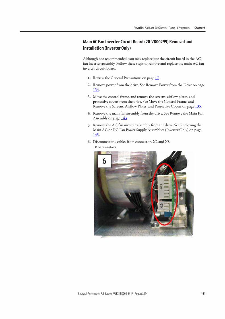
Rockwell Automation Publication PFLEX-IN029B-EN-P - August 2014 151
PowerFlex 700H and 700S Drives - Frame 13 Procedures Chapter 5
Main AC Fan Inverter Circuit Board (20-VB00299) Removal and
Installation (Inverter Only)
Although not recommended, you may replace just the circuit board in the AC fan inverter assembly. Follow these steps to remove and replace the main AC fan inverter circuit board.
1. Review the General Precautions on page 17.
2. Remove power from the drive. See Remove Power from the Drive on page 134.
3. Move the control frame, and remove the screens, airflow plates, and protective covers from the drive. See Move the Control Frame, and Remove the Screens, Airflow Plates, and Protective Covers on page 135.
4. Remove the main fan assembly from the drive. See Remove the Main Fan Assembly on page 143.
5. Remove the AC fan inverter assembly from the drive. See Removing the Main AC or DC Fan Power Supply Assemblies (Inverter Only) on page 145.
6. Disconnect the cables from connectors X2 and X8. AC fan system shown.
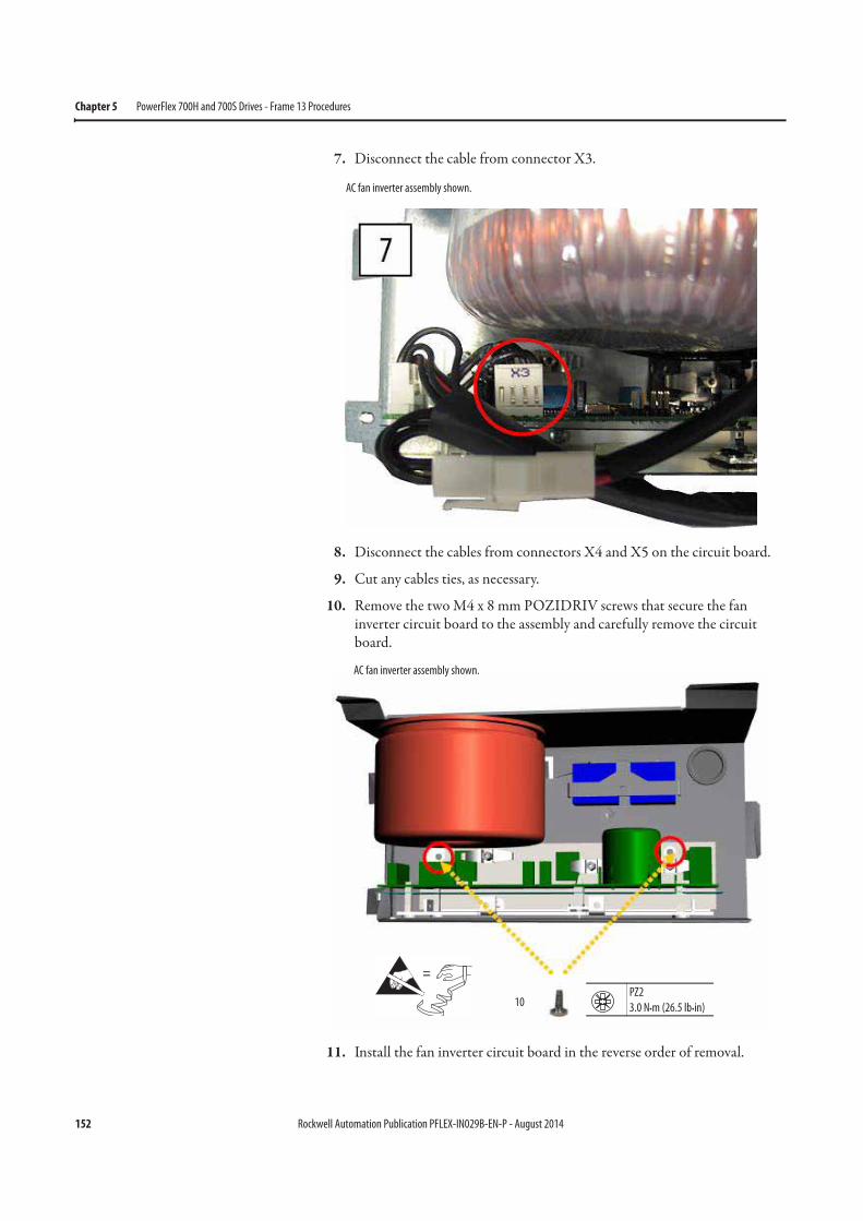
152 Rockwell Automation Publication PFLEX-IN029B-EN-P - August 2014
Chapter 5 PowerFlex 700H and 700S Drives - Frame 13 Procedures
7. Disconnect the cable from connector X3.
8. Disconnect the cables from connectors X4 and X5 on the circuit board.
9. Cut any cables ties, as necessary.
10. Remove the two M4 x 8 mm POZIDRIV screws that secure the fan inverter circuit board to the assembly and carefully remove the circuit board.
11. Install the fan inverter circuit board in the reverse order of removal.
AC fan inverter assembly shown.
=
10PZ2
3.0 N•m (26.5 lb•in)
AC fan inverter assembly shown.
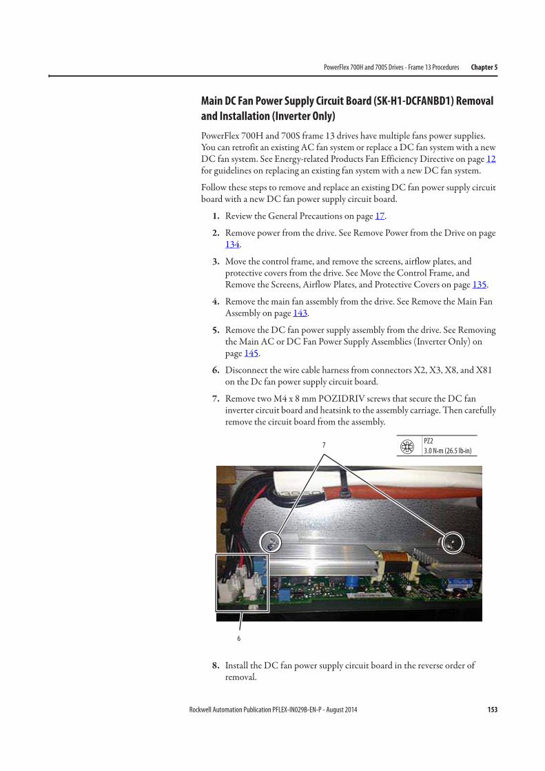
Rockwell Automation Publication PFLEX-IN029B-EN-P - August 2014 153
PowerFlex 700H and 700S Drives - Frame 13 Procedures Chapter 5
Main DC Fan Power Supply Circuit Board (SK-H1-DCFANBD1) Removal
and Installation (Inverter Only)
PowerFlex 700H and 700S frame 13 drives have multiple fans power supplies. You can retrofit an existing AC fan system or replace a DC fan system with a new DC fan system. See Energy-related Products Fan Efficiency Directive on page 12 for guidelines on replacing an existing fan system with a new DC fan system.
Follow these steps to remove and replace an existing DC fan power supply circuit board with a new DC fan power supply circuit board.
1. Review the General Precautions on page 17.
2. Remove power from the drive. See Remove Power from the Drive on page 134.
3. Move the control frame, and remove the screens, airflow plates, and protective covers from the drive. See Move the Control Frame, and Remove the Screens, Airflow Plates, and Protective Covers on page 135.
4. Remove the main fan assembly from the drive. See Remove the Main Fan Assembly on page 143.
5. Remove the DC fan power supply assembly from the drive. See Removing the Main AC or DC Fan Power Supply Assemblies (Inverter Only) on page 145.
6. Disconnect the wire cable harness from connectors X2, X3, X8, and X81 on the Dc fan power supply circuit board.
7. Remove two M4 x 8 mm POZIDRIV screws that secure the DC fan inverter circuit board and heatsink to the assembly carriage. Then carefully remove the circuit board from the assembly.
8. Install the DC fan power supply circuit board in the reverse order of removal.
PZ2
3.0 N•m (26.5 lb•in)
6
7
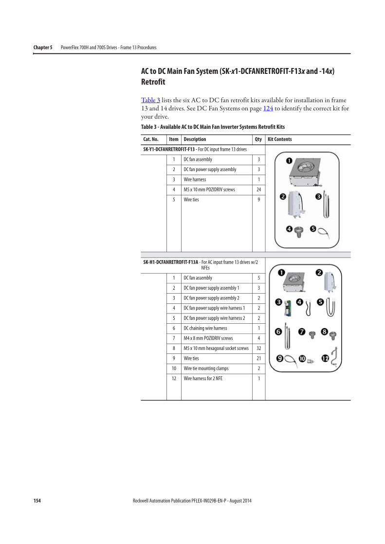
154 Rockwell Automation Publication PFLEX-IN029B-EN-P - August 2014
Chapter 5 PowerFlex 700H and 700S Drives - Frame 13 Procedures
AC to DC Main Fan System (SK-x1-DCFANRETROFIT-F13x and -14x)
Retrofit
Table 3 lists the six AC to DC fan retrofit kits available for installation in frame 13 and 14 drives. See DC Fan Systems on page 124 to identify the correct kit for your drive. Table 3 - Available AC to DC Main Fan Inverter Systems Retrofit Kits
Cat. No. Item Description Qty Kit Contents
SK-Y1-DCFANRETROFIT-F13 - For DC input frame 13 drives
1 DC fan assembly 3
2 DC fan power supply assembly 3
3 Wire harness 1
4 M5 x 10 mm POZIDRIV screws 24
5 Wire ties 9
SK-H1-DCFANRETROFIT-F13A - For AC input frame 13 drives w/2 NFEs
1 DC fan assembly 5
2 DC fan power supply assembly 1 3
3 DC fan power supply assembly 2 2
4 DC fan power supply wire harness 1 2
5 DC fan power supply wire harness 2 2
6 DC chaining wire harness 1
7 M4 x 8 mm POZIDRIV screws 4
8 M5 x 10 mm hexagonal socket screws 32
9 Wire ties 21
10 Wire tie mounting clamps 2
12 Wire harness for 2 NFE 1
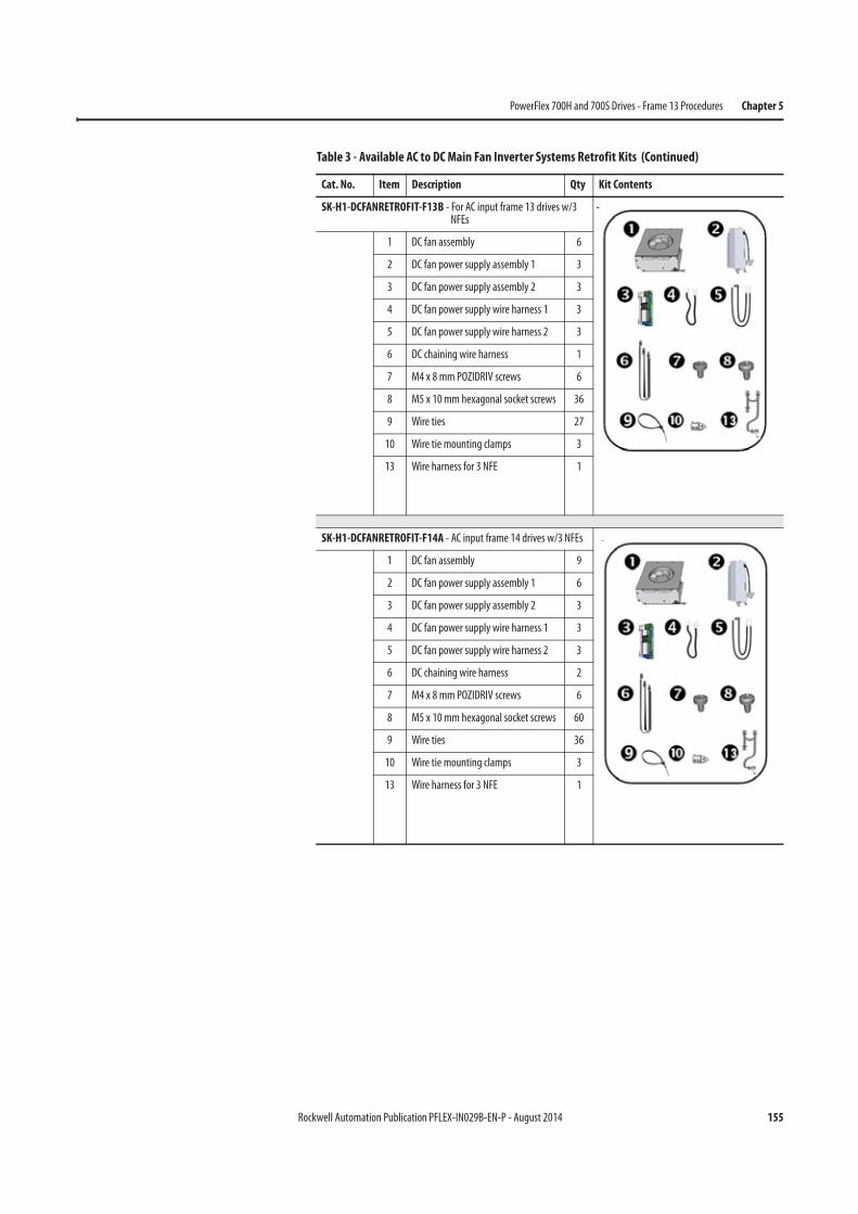
Rockwell Automation Publication PFLEX-IN029B-EN-P - August 2014 155
PowerFlex 700H and 700S Drives - Frame 13 Procedures Chapter 5
SK-H1-DCFANRETROFIT-F13B - For AC input frame 13 drives w/3 NFEs
1 DC fan assembly 6
2 DC fan power supply assembly 1 3
3 DC fan power supply assembly 2 3
4 DC fan power supply wire harness 1 3
5 DC fan power supply wire harness 2 3
6 DC chaining wire harness 1
7 M4 x 8 mm POZIDRIV screws 6
8 M5 x 10 mm hexagonal socket screws 36
9 Wire ties 27
10 Wire tie mounting clamps 3
13 Wire harness for 3 NFE 1
SK-H1-DCFANRETROFIT-F14A - AC input frame 14 drives w/3 NFEs
1 DC fan assembly 9
2 DC fan power supply assembly 1 6
3 DC fan power supply assembly 2 3
4 DC fan power supply wire harness 1 3
5 DC fan power supply wire harness 2 3
6 DC chaining wire harness 2
7 M4 x 8 mm POZIDRIV screws 6
8 M5 x 10 mm hexagonal socket screws 60
9 Wire ties 36
10 Wire tie mounting clamps 3
13 Wire harness for 3 NFE 1
Table 3 - Available AC to DC Main Fan Inverter Systems Retrofit Kits (Continued)
Cat. No. Item Description Qty Kit Contents
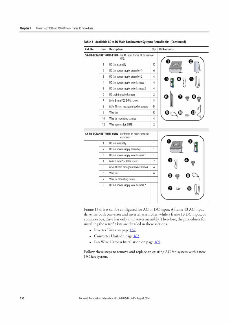
156 Rockwell Automation Publication PFLEX-IN029B-EN-P - August 2014
Chapter 5 PowerFlex 700H and 700S Drives - Frame 13 Procedures
Frame 13 drives can be configured for AC or DC input. A frame 13 AC input drive has both converter and inverter assemblies, while a frame 13 DC input, or common bus, drive has only an inverter assembly. Therefore, the procedures for installing the retrofit kits are detailed in these sections:
• Inverter Units on page 157• Converter Units on page 162• Fan Wire Harness Installation on page 165
Follow these steps to remove and replace an existing AC fan system with a new DC fan system.
SK-H1-DCFANRETROFIT-F14B - For AC input frame 14 drives w/4 NFEs
1 DC fan assembly 10
2 DC fan power supply assembly 1 6
3 DC fan power supply assembly 2 4
4 DC fan power supply wire harness 1 4
5 DC fan power supply wire harness 2 4
6 DC chaining wire harness 2
7 M4 x 8 mm POZIDRIV screws 8
8 M5 x 10 mm hexagonal socket screws 64
9 Wire ties 42
10 Wire tie mounting clamps 4
12 Wire harness for 2 NFE 2
SK-H1-DCFANRETROFIT-CONV - For frame 14 drive converter extension
1 DC fan assembly 1
2 DC fan power supply assembly 1
3 DC fan power supply wire harness 1 1
4 M4 x 8 mm POZIDRIV screws 2
5 M5 x 10 mm hexagonal socket screws 4
6 Wire ties 6
7 Wire tie mounting clamp 1
9 DC fan power supply wire harness 2 1
Table 3 - Available AC to DC Main Fan Inverter Systems Retrofit Kits (Continued)
Cat. No. Item Description Qty Kit Contents

Rockwell Automation Publication PFLEX-IN029B-EN-P - August 2014 157
PowerFlex 700H and 700S Drives - Frame 13 Procedures Chapter 5
Inverter Units
1. Review the General Precautions on page 17.
2. Remove power from the drive. See Remove Power from the Drive on page 134.
3. Move the control frame, and remove the screens, airflow plates, and protective covers. See Move the Control Frame, and Remove the Screens, Airflow Plates, and Protective Covers on page 135.
4. Remove the main fan assemblies. See Remove the Main Fan Assembly on page 143.
5. Remove the AC fan inverter assemblies. See Removing the Main AC or DC Fan Power Supply Assemblies (Inverter Only) on page 145.
6. For AC input standalone drives only, remove the wire harness that connects the fans on the converter and inverter units.
Note: DC input drives do not have an converter section, so there is no converter to inverter interconnect wire harness.
6
Converter Section Inverter Section
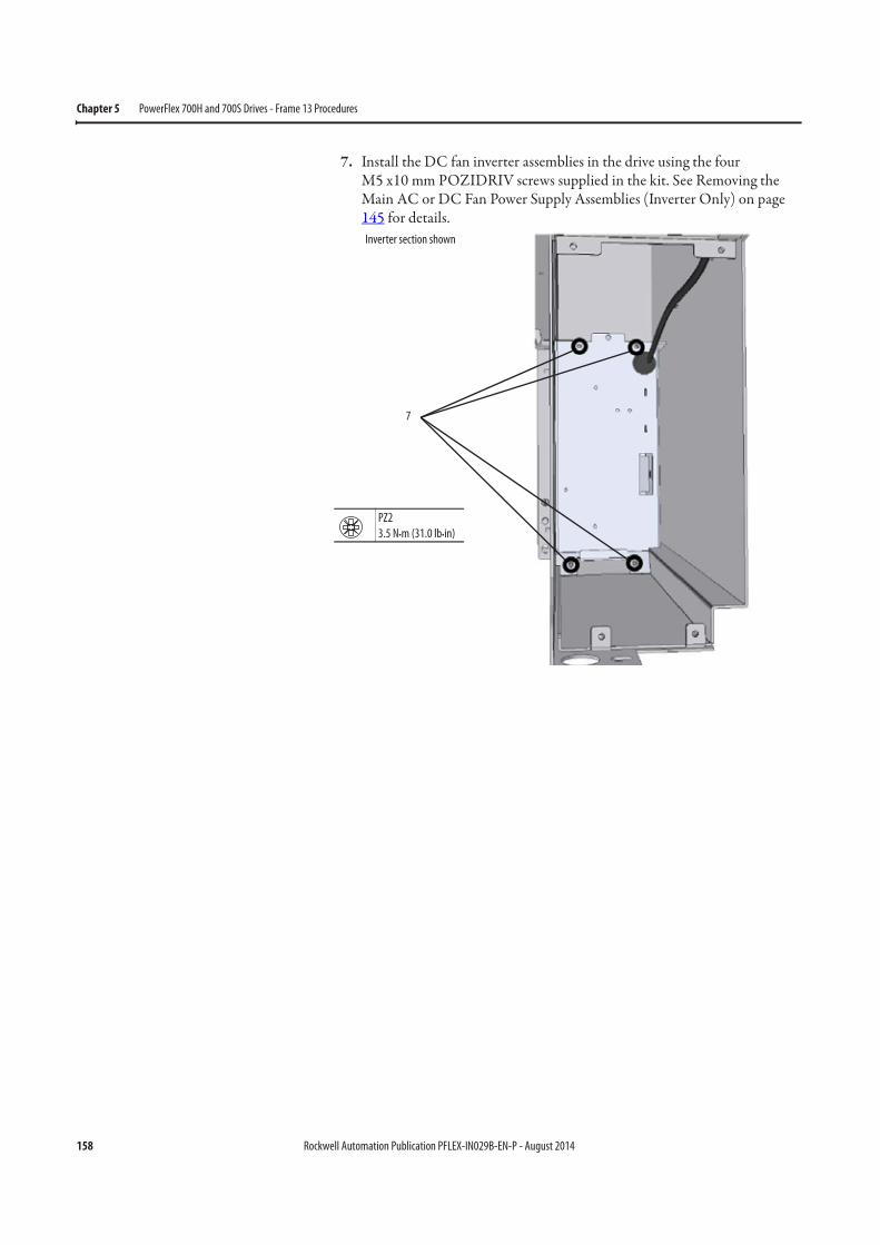
158 Rockwell Automation Publication PFLEX-IN029B-EN-P - August 2014
Chapter 5 PowerFlex 700H and 700S Drives - Frame 13 Procedures
7. Install the DC fan inverter assemblies in the drive using the four M5 x10 mm POZIDRIV screws supplied in the kit. See Removing the Main AC or DC Fan Power Supply Assemblies (Inverter Only) on page 145 for details.
7
PZ2
3.5 N•m (31.0 lb•in)
Inverter section shown
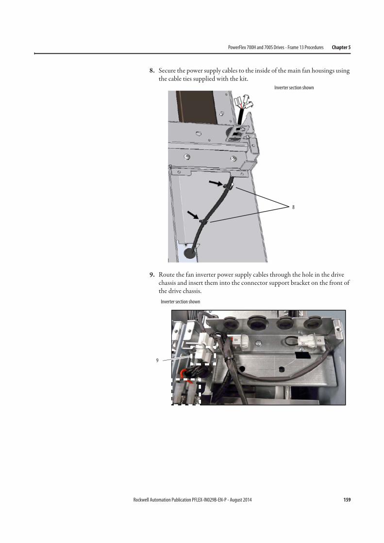
Rockwell Automation Publication PFLEX-IN029B-EN-P - August 2014 159
PowerFlex 700H and 700S Drives - Frame 13 Procedures Chapter 5
8. Secure the power supply cables to the inside of the main fan housings using the cable ties supplied with the kit.
9. Route the fan inverter power supply cables through the hole in the drive chassis and insert them into the connector support bracket on the front of the drive chassis.
8
Inverter section shown
9
Inverter section shown
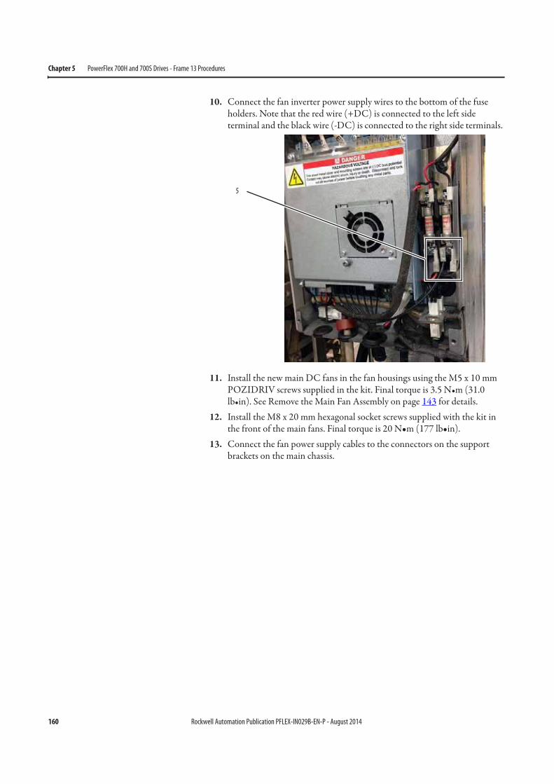
160 Rockwell Automation Publication PFLEX-IN029B-EN-P - August 2014
Chapter 5 PowerFlex 700H and 700S Drives - Frame 13 Procedures
10. Connect the fan inverter power supply wires to the bottom of the fuse holders. Note that the red wire (+DC) is connected to the left side terminal and the black wire (-DC) is connected to the right side terminals.
11. Install the new main DC fans in the fan housings using the M5 x 10 mm POZIDRIV screws supplied in the kit. Final torque is 3.5 N•m (31.0 lb•in). See Remove the Main Fan Assembly on page 143 for details.
12. Install the M8 x 20 mm hexagonal socket screws supplied with the kit in the front of the main fans. Final torque is 20 N•m (177 lb•in).
13. Connect the fan power supply cables to the connectors on the support brackets on the main chassis.
5
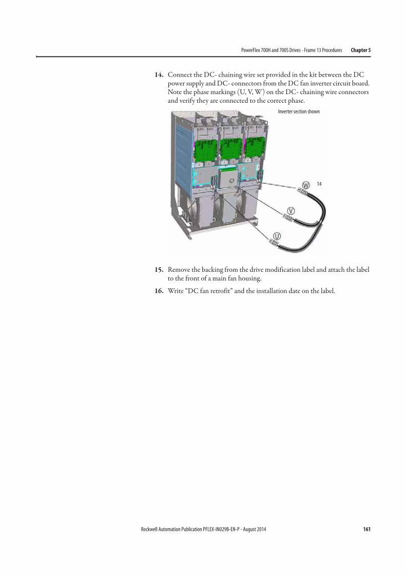
Rockwell Automation Publication PFLEX-IN029B-EN-P - August 2014 161
PowerFlex 700H and 700S Drives - Frame 13 Procedures Chapter 5
14. Connect the DC- chaining wire set provided in the kit between the DC power supply and DC- connectors from the DC fan inverter circuit board. Note the phase markings (U, V, W) on the DC- chaining wire connectors and verify they are connected to the correct phase.
15. Remove the backing from the drive modification label and attach the label to the front of a main fan housing.
16. Write “DC fan retrofit” and the installation date on the label.
14
Inverter section shown
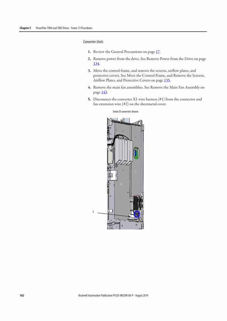
162 Rockwell Automation Publication PFLEX-IN029B-EN-P - August 2014
Chapter 5 PowerFlex 700H and 700S Drives - Frame 13 Procedures
Converter Units
1. Review the General Precautions on page 17.
2. Remove power from the drive. See Remove Power from the Drive on page 134.
3. Move the control frame, and remove the screens, airflow plates, and protective covers. See Move the Control Frame, and Remove the Screens, Airflow Plates, and Protective Covers on page 135.
4. Remove the main fan assemblies. See Remove the Main Fan Assembly on page 143.
5. Disconnect the converter X1 wire harness (#1) from the connector and fan extension wire (#2) on the sheetmetal cover.
5
Series B converter shown
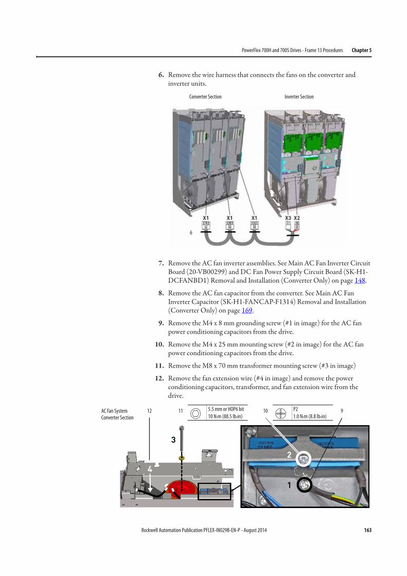
Rockwell Automation Publication PFLEX-IN029B-EN-P - August 2014 163
PowerFlex 700H and 700S Drives - Frame 13 Procedures Chapter 5
6. Remove the wire harness that connects the fans on the converter and inverter units.
7. Remove the AC fan inverter assemblies. See Main AC Fan Inverter Circuit Board (20-VB00299) and DC Fan Power Supply Circuit Board (SK-H1-DCFANBD1) Removal and Installation (Converter Only) on page 148.
8. Remove the AC fan capacitor from the converter. See Main AC Fan Inverter Capacitor (SK-H1-FANCAP-F1314) Removal and Installation (Converter Only) on page 169.
9. Remove the M4 x 8 mm grounding screw (#1 in image) for the AC fan power conditioning capacitors from the drive.
10. Remove the M4 x 25 mm mounting screw (#2 in image) for the AC fan power conditioning capacitors from the drive.
11. Remove the M8 x 70 mm transformer mounting screw (#3 in image)
12. Remove the fan extension wire (#4 in image) and remove the power conditioning capacitors, transformer, and fan extension wire from the drive.
6
Converter Section Inverter Section
11 10 912 P2
1.0 N•m (8.8 lb•in)
5.5 mm or HOP6 bit
10 N•m (88.5 lb•in)AC Fan System Converter Section
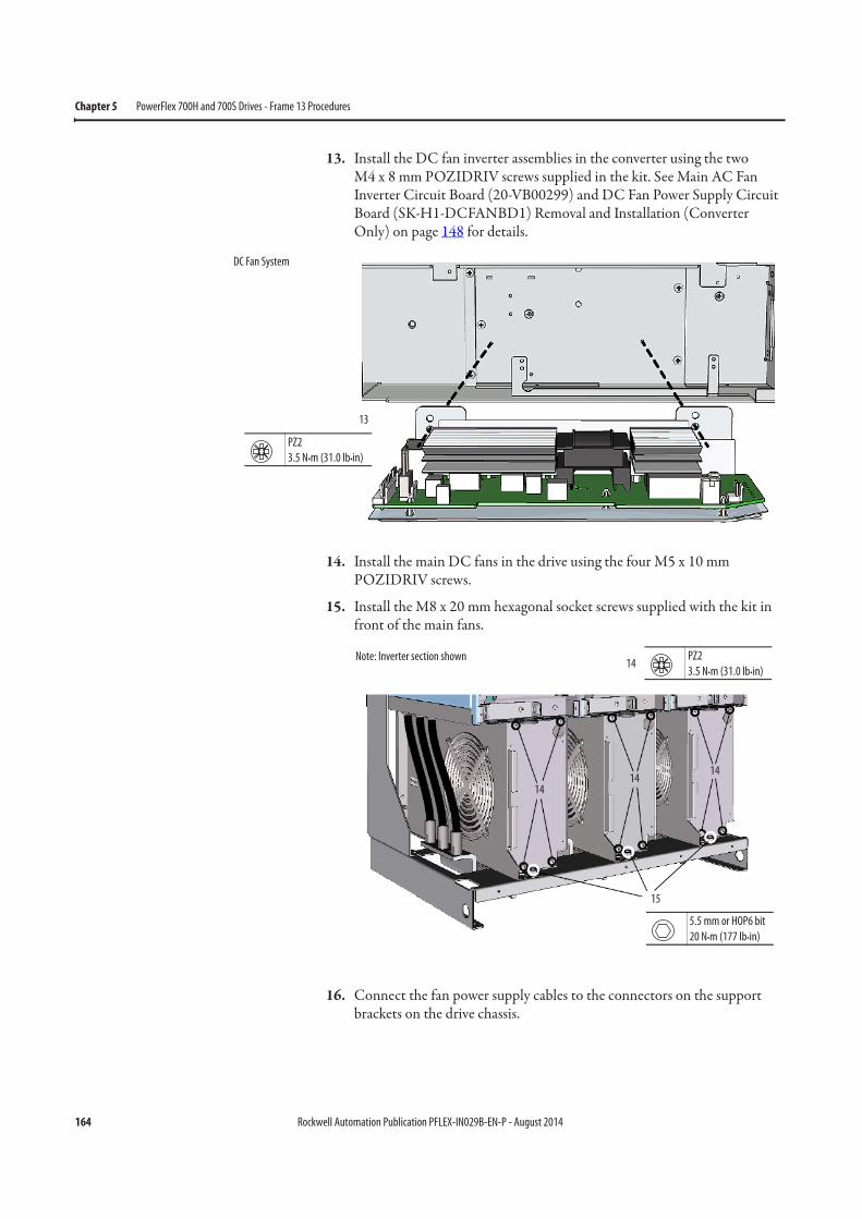
164 Rockwell Automation Publication PFLEX-IN029B-EN-P - August 2014
Chapter 5 PowerFlex 700H and 700S Drives - Frame 13 Procedures
13. Install the DC fan inverter assemblies in the converter using the two M4 x 8 mm POZIDRIV screws supplied in the kit. See Main AC Fan Inverter Circuit Board (20-VB00299) and DC Fan Power Supply Circuit Board (SK-H1-DCFANBD1) Removal and Installation (Converter Only) on page 148 for details.
14. Install the main DC fans in the drive using the four M5 x 10 mm POZIDRIV screws.
15. Install the M8 x 20 mm hexagonal socket screws supplied with the kit in front of the main fans.
16. Connect the fan power supply cables to the connectors on the support brackets on the drive chassis.
13
PZ2
3.5 N•m (31.0 lb•in)
DC Fan System
PZ2
3.5 N•m (31.0 lb•in)
1414
14
15
14
5.5 mm or HOP6 bit
20 N•m (177 lb•in)
Note: Inverter section shown
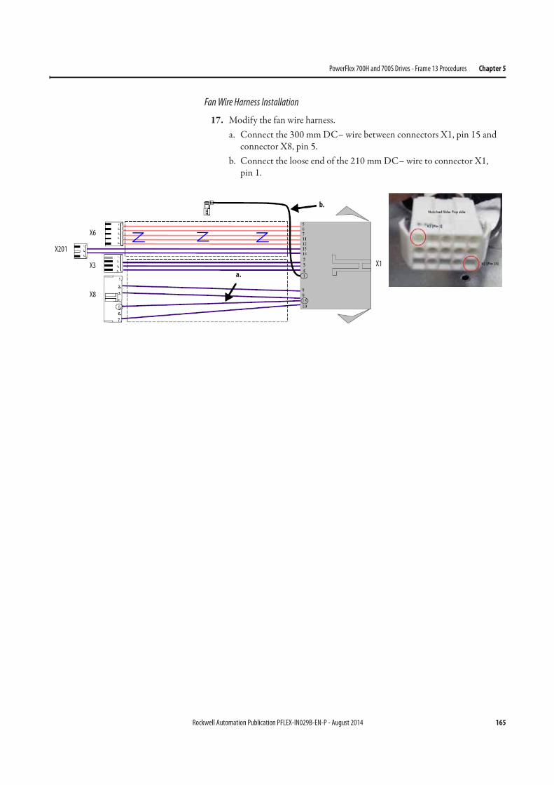
Rockwell Automation Publication PFLEX-IN029B-EN-P - August 2014 165
PowerFlex 700H and 700S Drives - Frame 13 Procedures Chapter 5
Fan Wire Harness Installation
17. Modify the fan wire harness.a. Connect the 300 mm DC– wire between connectors X1, pin 15 and
connector X8, pin 5.b. Connect the loose end of the 210 mm DC– wire to connector X1,
pin 1.
X201
X8
X3
X6
X1
a.
b.
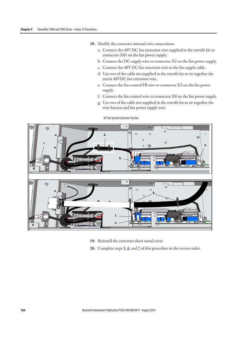
166 Rockwell Automation Publication PFLEX-IN029B-EN-P - August 2014
Chapter 5 PowerFlex 700H and 700S Drives - Frame 13 Procedures
18. Modify the converter internal wire connections.a. Connect the 48V DC fan extension wire supplied in the retrofit kit to
connector X81 on the fan power supply.b. Connect the DC supply wire to connector X2 on the fan power supply.c. Connect the 48V DC fan extension wire to the fan supply cable.d. Use two of the cable ties supplied in the retrofit kit to tie together the
excess 48VDC fan extension wire.e. Connect the fan control FB wire to connector X3 on the fan power
supply.f. Connect the fan control wire to connector X8 on the fan power supply.g. Use two of the cable ties supplied in the retrofit kit to tie together the
wire harness and fan power supply wire.
19. Reinstall the converter sheet metal cover.
20. Complete steps 5, 6, and 7 of this procedure in the reverse order.
a.
b.
c.
d.
e.
f.
g.
DC Fan System Converter Section
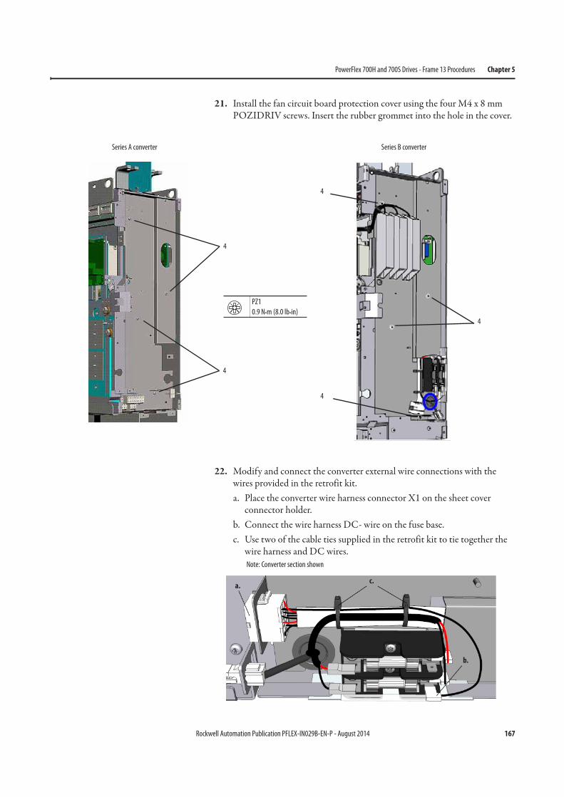
Rockwell Automation Publication PFLEX-IN029B-EN-P - August 2014 167
PowerFlex 700H and 700S Drives - Frame 13 Procedures Chapter 5
21. Install the fan circuit board protection cover using the four M4 x 8 mm POZIDRIV screws. Insert the rubber grommet into the hole in the cover.
22. Modify and connect the converter external wire connections with the wires provided in the retrofit kit.a. Place the converter wire harness connector X1 on the sheet cover
connector holder.b. Connect the wire harness DC- wire on the fuse base.c. Use two of the cable ties supplied in the retrofit kit to tie together the
wire harness and DC wires.
4
4
PZ1
0.9 N•m (8.0 lb•in)
Series A converter
4
4
4
Series B converter
a.
b.
c.
Note: Converter section shown
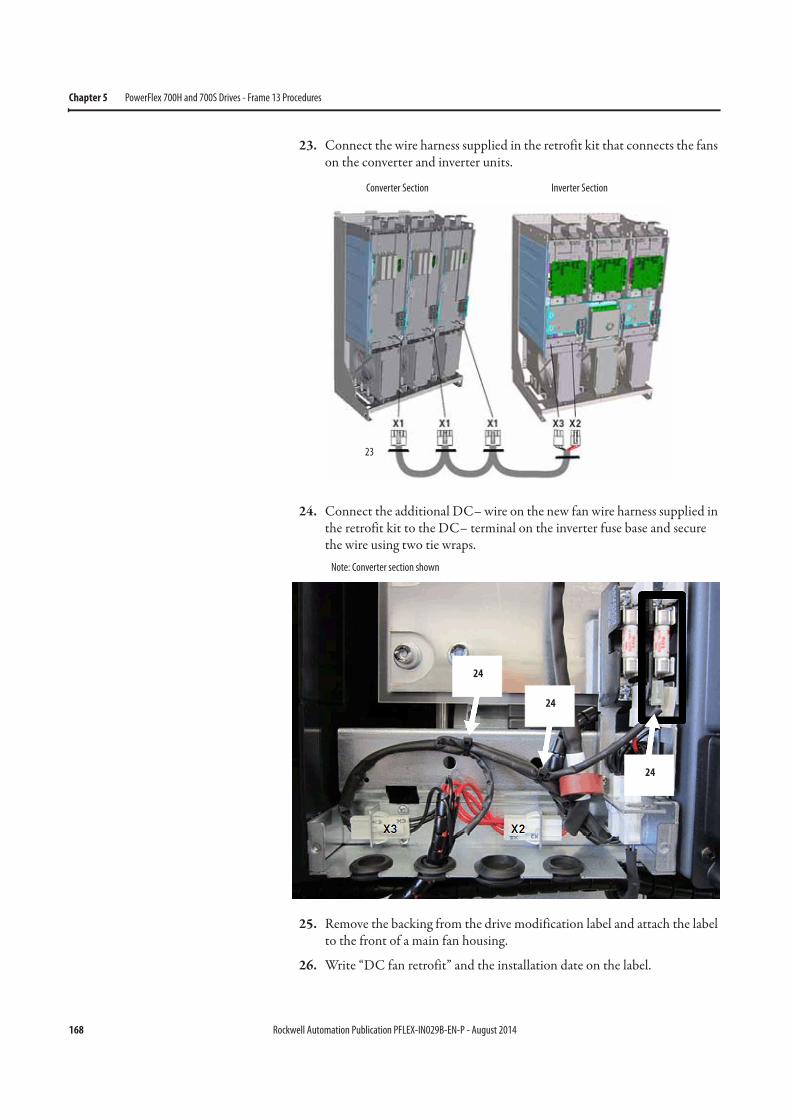
168 Rockwell Automation Publication PFLEX-IN029B-EN-P - August 2014
Chapter 5 PowerFlex 700H and 700S Drives - Frame 13 Procedures
23. Connect the wire harness supplied in the retrofit kit that connects the fans on the converter and inverter units.
24. Connect the additional DC– wire on the new fan wire harness supplied in the retrofit kit to the DC– terminal on the inverter fuse base and secure the wire using two tie wraps.
25. Remove the backing from the drive modification label and attach the label to the front of a main fan housing.
26. Write “DC fan retrofit” and the installation date on the label.
23
Converter Section Inverter Section
24
24
24
Note: Converter section shown
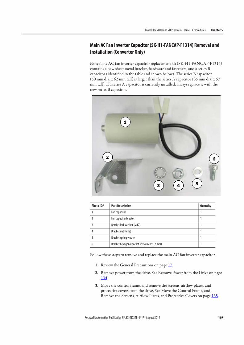
Rockwell Automation Publication PFLEX-IN029B-EN-P - August 2014 169
PowerFlex 700H and 700S Drives - Frame 13 Procedures Chapter 5
Main AC Fan Inverter Capacitor (SK-H1-FANCAP-F1314) Removal and
Installation (Converter Only)
Note: The AC fan inverter capacitor replacement kit (SK-H1-FANCAP-F1314) contains a new sheet metal bracket, hardware and fasteners, and a series B capacitor (identified in the table and shown below). The series B capacitor (50 mm dia. x 62 mm tall) is larger than the series A capacitor (35 mm dia. x 57 mm tall). If a series A capacitor is currently installed, always replace it with the new series B capacitor.
Follow these steps to remove and replace the main AC fan inverter capacitor.
1. Review the General Precautions on page 17.
2. Remove power from the drive. See Remove Power from the Drive on page 134.
3. Move the control frame, and remove the screens, airflow plates, and protective covers from the drive. See Move the Control Frame, and Remove the Screens, Airflow Plates, and Protective Covers on page 135.
Photo ID# Part Description Quantity
1 Fan capacitor 1
2 Fan capacitor bracket 1
3 Bracket lock washer (M12) 1
4 Bracket nut (M12) 1
5 Bracket spring washer 1
6 Bracket hexagonal socket screw (M8 x 12 mm) 1
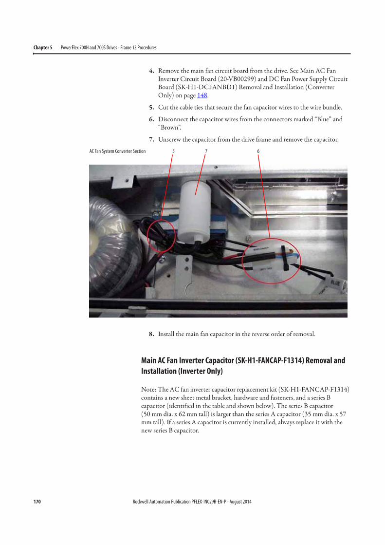
170 Rockwell Automation Publication PFLEX-IN029B-EN-P - August 2014
Chapter 5 PowerFlex 700H and 700S Drives - Frame 13 Procedures
4. Remove the main fan circuit board from the drive. See Main AC Fan Inverter Circuit Board (20-VB00299) and DC Fan Power Supply Circuit Board (SK-H1-DCFANBD1) Removal and Installation (Converter Only) on page 148.
5. Cut the cable ties that secure the fan capacitor wires to the wire bundle.
6. Disconnect the capacitor wires from the connectors marked “Blue” and “Brown”.
7. Unscrew the capacitor from the drive frame and remove the capacitor.
8. Install the main fan capacitor in the reverse order of removal.
Main AC Fan Inverter Capacitor (SK-H1-FANCAP-F1314) Removal and
Installation (Inverter Only)
Note: The AC fan inverter capacitor replacement kit (SK-H1-FANCAP-F1314) contains a new sheet metal bracket, hardware and fasteners, and a series B capacitor (identified in the table and shown below). The series B capacitor (50 mm dia. x 62 mm tall) is larger than the series A capacitor (35 mm dia. x 57 mm tall). If a series A capacitor is currently installed, always replace it with the new series B capacitor.
5 67AC Fan System Converter Section
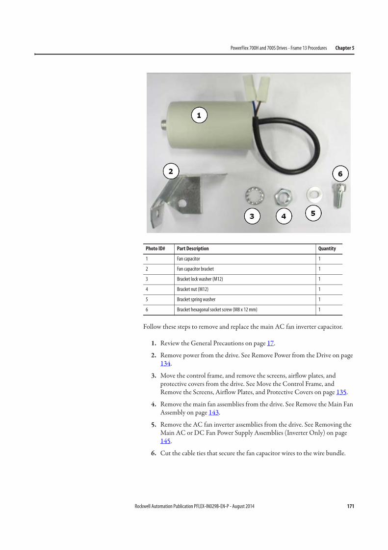
Rockwell Automation Publication PFLEX-IN029B-EN-P - August 2014 171
PowerFlex 700H and 700S Drives - Frame 13 Procedures Chapter 5
Follow these steps to remove and replace the main AC fan inverter capacitor.
1. Review the General Precautions on page 17.
2. Remove power from the drive. See Remove Power from the Drive on page 134.
3. Move the control frame, and remove the screens, airflow plates, and protective covers from the drive. See Move the Control Frame, and Remove the Screens, Airflow Plates, and Protective Covers on page 135.
4. Remove the main fan assemblies from the drive. See Remove the Main Fan Assembly on page 143.
5. Remove the AC fan inverter assemblies from the drive. See Removing the Main AC or DC Fan Power Supply Assemblies (Inverter Only) on page 145.
6. Cut the cable ties that secure the fan capacitor wires to the wire bundle.
Photo ID# Part Description Quantity
1 Fan capacitor 1
2 Fan capacitor bracket 1
3 Bracket lock washer (M12) 1
4 Bracket nut (M12) 1
5 Bracket spring washer 1
6 Bracket hexagonal socket screw (M8 x 12 mm) 1
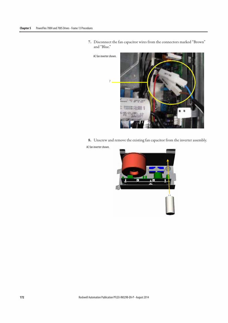
172 Rockwell Automation Publication PFLEX-IN029B-EN-P - August 2014
Chapter 5 PowerFlex 700H and 700S Drives - Frame 13 Procedures
7. Disconnect the fan capacitor wires from the connectors marked “Brown” and “Blue.”
8. Unscrew and remove the existing fan capacitor from the inverter assembly.
AC fan inverter shown.
AC fan inverter shown.
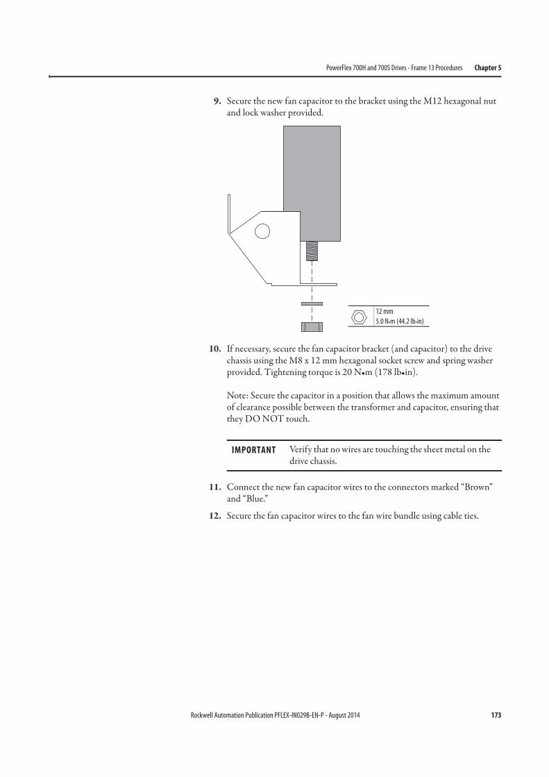
Rockwell Automation Publication PFLEX-IN029B-EN-P - August 2014 173
PowerFlex 700H and 700S Drives - Frame 13 Procedures Chapter 5
9. Secure the new fan capacitor to the bracket using the M12 hexagonal nut and lock washer provided.
10. If necessary, secure the fan capacitor bracket (and capacitor) to the drive chassis using the M8 x 12 mm hexagonal socket screw and spring washer provided. Tightening torque is 20 N•m (178 lb•in).
Note: Secure the capacitor in a position that allows the maximum amount of clearance possible between the transformer and capacitor, ensuring that they DO NOT touch.
11. Connect the new fan capacitor wires to the connectors marked “Brown” and “Blue.”
12. Secure the fan capacitor wires to the fan wire bundle using cable ties.
IMPORTANT Verify that no wires are touching the sheet metal on the drive chassis.
12 mm
5.0 N•m (44.2 lb•in)
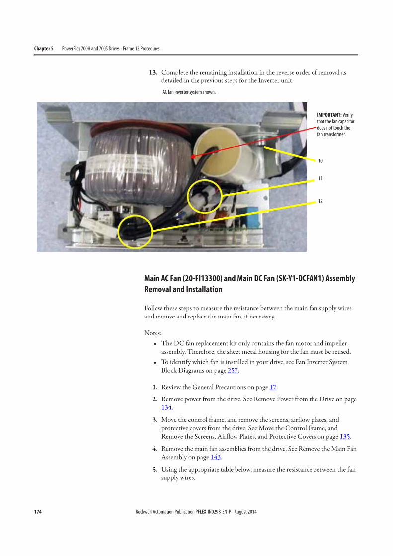
174 Rockwell Automation Publication PFLEX-IN029B-EN-P - August 2014
Chapter 5 PowerFlex 700H and 700S Drives - Frame 13 Procedures
13. Complete the remaining installation in the reverse order of removal as detailed in the previous steps for the Inverter unit.
Main AC Fan (20-FI13300) and Main DC Fan (SK-Y1-DCFAN1) Assembly
Removal and Installation
Follow these steps to measure the resistance between the main fan supply wires and remove and replace the main fan, if necessary.
Notes:• The DC fan replacement kit only contains the fan motor and impeller
assembly. Therefore, the sheet metal housing for the fan must be reused.• To identify which fan is installed in your drive, see Fan Inverter System
Block Diagrams on page 257.
1. Review the General Precautions on page 17.
2. Remove power from the drive. See Remove Power from the Drive on page 134.
3. Move the control frame, and remove the screens, airflow plates, and protective covers from the drive. See Move the Control Frame, and Remove the Screens, Airflow Plates, and Protective Covers on page 135.
4. Remove the main fan assemblies from the drive. See Remove the Main Fan Assembly on page 143.
5. Using the appropriate table below, measure the resistance between the fan supply wires.
IMPORTANT: Verify that the fan capacitor does not touch the fan transformer.
10
11
12
AC fan inverter system shown.
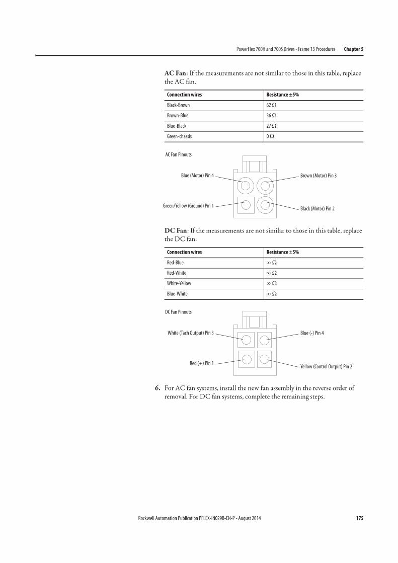
Rockwell Automation Publication PFLEX-IN029B-EN-P - August 2014 175
PowerFlex 700H and 700S Drives - Frame 13 Procedures Chapter 5
AC Fan: If the measurements are not similar to those in this table, replace the AC fan.
DC Fan: If the measurements are not similar to those in this table, replace the DC fan.
6. For AC fan systems, install the new fan assembly in the reverse order of removal. For DC fan systems, complete the remaining steps.
Connection wires Resistance ±5%
Black-Brown 62 Ω
Brown-Blue 36 Ω
Blue-Black 27 Ω
Green-chassis 0 Ω
Connection wires Resistance ±5%
Red-Blue ∞ Ω
Red-White ∞ Ω
White-Yellow ∞ Ω
Blue-White ∞ Ω
Blue (Motor) Pin 4
Green/Yellow (Ground) Pin 1
Brown (Motor) Pin 3
Black (Motor) Pin 2
AC Fan Pinouts
White (Tach Output) Pin 3
Red (+) Pin 1
Blue (-) Pin 4
Yellow (Control Output) Pin 2
DC Fan Pinouts
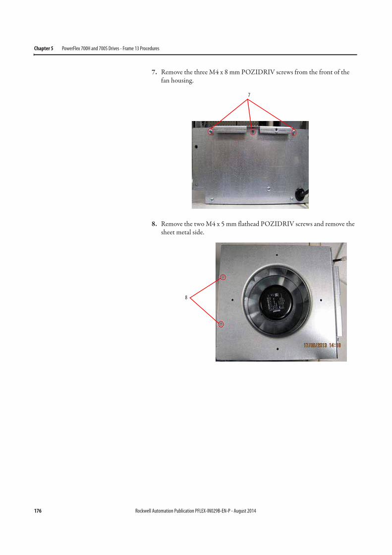
176 Rockwell Automation Publication PFLEX-IN029B-EN-P - August 2014
Chapter 5 PowerFlex 700H and 700S Drives - Frame 13 Procedures
7. Remove the three M4 x 8 mm POZIDRIV screws from the front of the fan housing.
8. Remove the two M4 x 5 mm flathead POZIDRIV screws and remove the sheet metal side.
7
8
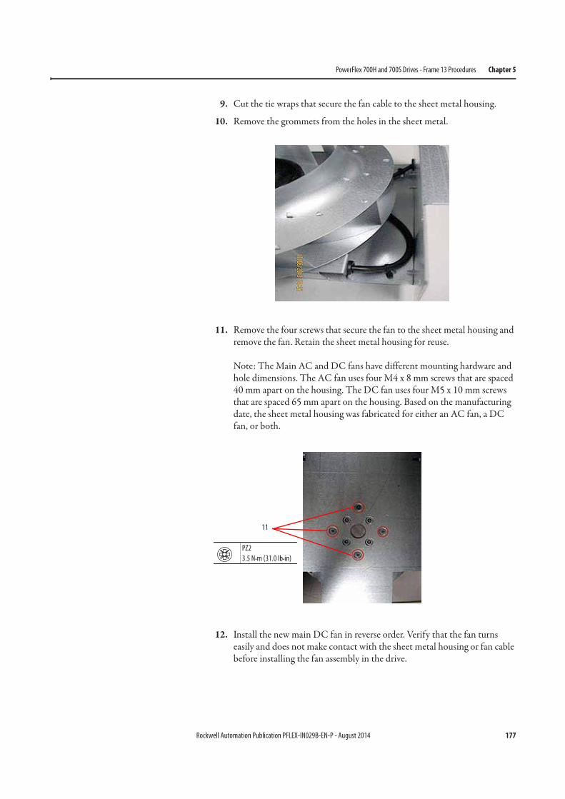
Rockwell Automation Publication PFLEX-IN029B-EN-P - August 2014 177
PowerFlex 700H and 700S Drives - Frame 13 Procedures Chapter 5
9. Cut the tie wraps that secure the fan cable to the sheet metal housing.
10. Remove the grommets from the holes in the sheet metal.
11. Remove the four screws that secure the fan to the sheet metal housing and remove the fan. Retain the sheet metal housing for reuse.
Note: The Main AC and DC fans have different mounting hardware and hole dimensions. The AC fan uses four M4 x 8 mm screws that are spaced 40 mm apart on the housing. The DC fan uses four M5 x 10 mm screws that are spaced 65 mm apart on the housing. Based on the manufacturing date, the sheet metal housing was fabricated for either an AC fan, a DC fan, or both.
12. Install the new main DC fan in reverse order. Verify that the fan turns easily and does not make contact with the sheet metal housing or fan cable before installing the fan assembly in the drive.
11
PZ2
3.5 N•m (31.0 lb•in)
178 Rockwell Automation Publication PFLEX-IN029B-EN-P - August 2014
Chapter 5 PowerFlex 700H and 700S Drives - Frame 13 Procedures
Notes:
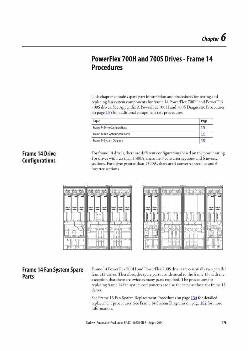
Rockwell Automation Publication PFLEX-IN029B-EN-P - August 2014 179
Chapter 6
PowerFlex 700H and 700S Drives - Frame 14 Procedures
This chapter contains spare part information and procedures for testing and replacing fan system components for frame 14 PowerFlex 700H and PowerFlex 700S drives. See Appendix A PowerFlex 700H and 700S Diagnostic Procedures on page 255 for additional component test procedures.
Frame 14 Drive Configurations
For frame 14 drives, there are different configurations based on the power rating. For drives with less than 1500A, there are 3 converter sections and 6 inverter sections. For drives greater than 1500A, there are 4 converter sections and 6 inverter sections.
Frame 14 Fan System Spare Parts
Frame 14 PowerFlex 700H and PowerFlex 700S drives are essentially two parallel frame13 drives. Therefore, the spare parts are identical to the frame 13, with the exception that there are twice as many parts required. The procedures for replacing frame 14 fan system components are also the same as those for frame 13 drives.
See Frame 13 Fan System Replacement Procedures on page 134 for detailed replacement procedures. See Frame 14 System Diagrams on page 182 for more information.
Topic Page
Frame 14 Drive Configurations 179
Frame 14 Fan System Spare Parts 179
Frame 14 System Diagrams 182