Embed Size (px)
Citation preview

PowerFlex 700S Adjustable Frequency AC Drive, Phase I ControlCatalog Numbers 20D
Reference Manual

Important User Information
Read this document and the documents listed in the additional resources section about installation, configuration, and operation of this equipment before you install, configure, operate, or maintain this product. Users are required to familiarize themselves with installation and wiring instructions in addition to requirements of all applicable codes, laws, and standards.
Activities including installation, adjustments, putting into service, use, assembly, disassembly, and maintenance are required to be carried out by suitably trained personnel in accordance with applicable code of practice.
If this equipment is used in a manner not specified by the manufacturer, the protection provided by the equipment may be impaired.
In no event will Rockwell Automation, Inc. be responsible or liable for indirect or consequential damages resulting from the use or application of this equipment.
The examples and diagrams in this manual are included solely for illustrative purposes. Because of the many variables and requirements associated with any particular installation, Rockwell Automation, Inc. cannot assume responsibility or liability for actual use based on the examples and diagrams.
No patent liability is assumed by Rockwell Automation, Inc. with respect to use of information, circuits, equipment, or software described in this manual.
Reproduction of the contents of this manual, in whole or in part, without written permission of Rockwell Automation, Inc., is prohibited.
Throughout this manual, when necessary, we use notes to make you aware of safety considerations.
Labels may also be on or inside the equipment to provide specific precautions.
Allen-Bradley, ControlLogix, DPI, DriveExecutive, DriveExplorer, DriveLogix, PLC-5, PowerFlex, Rockwell Software, Rockwell Automation, SCANport, SLC, and SynchLink are trademarks of Rockwell Automation, Inc.
Trademarks not belonging to Rockwell Automation are property of their respective companies.
WARNING: Identifies information about practices or circumstances that can cause an explosion in a hazardous environment, which may lead to personal injury or death, property damage, or economic loss.
ATTENTION: Identifies information about practices or circumstances that can lead to personal injury or death, property damage, or economic loss. Attentions help you identify a hazard, avoid a hazard, and recognize the consequence.
IMPORTANT Identifies information that is critical for successful application and understanding of the product.
SHOCK HAZARD: Labels may be on or inside the equipment, for example, a drive or motor, to alert people that dangerous voltage may be present.
BURN HAZARD: Labels may be on or inside the equipment, for example, a drive or motor, to alert people that surfaces may reach dangerous temperatures.
ARC FLASH HAZARD: Labels may be on or inside the equipment, for example, a motor control center, to alert people to potential Arc Flash. Arc Flash will cause severe injury or death. Wear proper Personal Protective Equipment (PPE). Follow ALL Regulatory requirements for safe work practices and for Personal Protective Equipment (PPE).

Summary of Changes
This manual contains new and updated information.
New and Updated Information
This table contains the changes made to this revision.
Changes to this manual for previous revisions are included in Appendix A History of Changes on page 183.
Topic See
Removed the Specification and Dimension information (Chapter 1) 20D-UM001
Removed fuse and circuit breaker information and tables 20D-UM001
Rockwell Automation Publication PFLEX-RM002D-EN-E - August 2013 3

Summary of Changes
Notes:
4 Rockwell Automation Publication PFLEX-RM002D-EN-E - August 2013

Table of Contents
Preface Additional Resources . . . . . . . . . . . . . . . . . . . . . . . . . . . . . . . . . . . . . . . . . . . . . 11
Chapter 1Detail Drive Configuration and Operation
Accel Time . . . . . . . . . . . . . . . . . . . . . . . . . . . . . . . . . . . . . . . . . . . . . . . . . . . . . . 13Alarms . . . . . . . . . . . . . . . . . . . . . . . . . . . . . . . . . . . . . . . . . . . . . . . . . . . . . . . . . . 13
Configuration: . . . . . . . . . . . . . . . . . . . . . . . . . . . . . . . . . . . . . . . . . . . . . . . 13Application Example: . . . . . . . . . . . . . . . . . . . . . . . . . . . . . . . . . . . . . . . . . 14
Analog Inputs . . . . . . . . . . . . . . . . . . . . . . . . . . . . . . . . . . . . . . . . . . . . . . . . . . . 14Analog Input Specifications . . . . . . . . . . . . . . . . . . . . . . . . . . . . . . . . . . . 14Analog Input Configuration . . . . . . . . . . . . . . . . . . . . . . . . . . . . . . . . . . 14
Analog Outputs. . . . . . . . . . . . . . . . . . . . . . . . . . . . . . . . . . . . . . . . . . . . . . . . . . 15Analog Output Specifications . . . . . . . . . . . . . . . . . . . . . . . . . . . . . . . . . 15Analog Output Configuration. . . . . . . . . . . . . . . . . . . . . . . . . . . . . . . . . 16
Auto/Manual . . . . . . . . . . . . . . . . . . . . . . . . . . . . . . . . . . . . . . . . . . . . . . . . . . . . 17Autotune. . . . . . . . . . . . . . . . . . . . . . . . . . . . . . . . . . . . . . . . . . . . . . . . . . . . . . . . 17
Autotune - Start-Up Menu. . . . . . . . . . . . . . . . . . . . . . . . . . . . . . . . . . . . 17Motor Control . . . . . . . . . . . . . . . . . . . . . . . . . . . . . . . . . . . . . . . . . . . . . . . 18Motor Data . . . . . . . . . . . . . . . . . . . . . . . . . . . . . . . . . . . . . . . . . . . . . . . . . . 18Feedback Configuration . . . . . . . . . . . . . . . . . . . . . . . . . . . . . . . . . . . . . . 18Power Circuit Test . . . . . . . . . . . . . . . . . . . . . . . . . . . . . . . . . . . . . . . . . . . 18Direction Test . . . . . . . . . . . . . . . . . . . . . . . . . . . . . . . . . . . . . . . . . . . . . . . 19Motor Tests . . . . . . . . . . . . . . . . . . . . . . . . . . . . . . . . . . . . . . . . . . . . . . . . . 19Inertia Test . . . . . . . . . . . . . . . . . . . . . . . . . . . . . . . . . . . . . . . . . . . . . . . . . . 20Troubleshooting a “MC Commissn Fail” Fault during Autotune . 20
Auxiliary Power Supply . . . . . . . . . . . . . . . . . . . . . . . . . . . . . . . . . . . . . . . . . . . 20Frames 9 & Up. . . . . . . . . . . . . . . . . . . . . . . . . . . . . . . . . . . . . . . . . . . . . . . 20
Bus Regulation/Braking . . . . . . . . . . . . . . . . . . . . . . . . . . . . . . . . . . . . . . . . . . 20Description . . . . . . . . . . . . . . . . . . . . . . . . . . . . . . . . . . . . . . . . . . . . . . . . . . 20Technical Information. . . . . . . . . . . . . . . . . . . . . . . . . . . . . . . . . . . . . . . . 21Bus Regulator/Braking Configuration. . . . . . . . . . . . . . . . . . . . . . . . . . 21
Cable, Control. . . . . . . . . . . . . . . . . . . . . . . . . . . . . . . . . . . . . . . . . . . . . . . . . . . 24Cable, Motor Lengths . . . . . . . . . . . . . . . . . . . . . . . . . . . . . . . . . . . . . . . . . . . . 24Cable, Power . . . . . . . . . . . . . . . . . . . . . . . . . . . . . . . . . . . . . . . . . . . . . . . . . . . . 24Cable Trays and Conduit . . . . . . . . . . . . . . . . . . . . . . . . . . . . . . . . . . . . . . . . . 24Carrier (PWM) Frequency. . . . . . . . . . . . . . . . . . . . . . . . . . . . . . . . . . . . . . . . 25CE Conformity . . . . . . . . . . . . . . . . . . . . . . . . . . . . . . . . . . . . . . . . . . . . . . . . . . 26
Low Voltage Directive (2006/95/EC). . . . . . . . . . . . . . . . . . . . . . . . . . 26EMC Directive (2004/108/EC) . . . . . . . . . . . . . . . . . . . . . . . . . . . . . . . 26
Common Bus Systems . . . . . . . . . . . . . . . . . . . . . . . . . . . . . . . . . . . . . . . . . . . . 26Communication . . . . . . . . . . . . . . . . . . . . . . . . . . . . . . . . . . . . . . . . . . . . . . . . . 26ControlNet (20-COMM-C). . . . . . . . . . . . . . . . . . . . . . . . . . . . . . . . . . . . . . 26
Setup Information. . . . . . . . . . . . . . . . . . . . . . . . . . . . . . . . . . . . . . . . . . . . 26Technical Information. . . . . . . . . . . . . . . . . . . . . . . . . . . . . . . . . . . . . . . . 28ControlLogix Programming . . . . . . . . . . . . . . . . . . . . . . . . . . . . . . . . . . . 31Datalink Programming . . . . . . . . . . . . . . . . . . . . . . . . . . . . . . . . . . . . . . . 32
Rockwell Automation Publication PFLEX-RM002D-EN-E - August 2013 5

Table of Contents
Explicit Messaging . . . . . . . . . . . . . . . . . . . . . . . . . . . . . . . . . . . . . . . . . . . . 32Copy Cat . . . . . . . . . . . . . . . . . . . . . . . . . . . . . . . . . . . . . . . . . . . . . . . . . . . . . . . . 33Current Limit. . . . . . . . . . . . . . . . . . . . . . . . . . . . . . . . . . . . . . . . . . . . . . . . . . . . 33Datalinks . . . . . . . . . . . . . . . . . . . . . . . . . . . . . . . . . . . . . . . . . . . . . . . . . . . . . . . . 34
Configuring Datalinks . . . . . . . . . . . . . . . . . . . . . . . . . . . . . . . . . . . . . . . . 34Decel Time . . . . . . . . . . . . . . . . . . . . . . . . . . . . . . . . . . . . . . . . . . . . . . . . . . . . . . 36DeviceNet (20-COMM-D) . . . . . . . . . . . . . . . . . . . . . . . . . . . . . . . . . . . . . . . 36
Technical Information . . . . . . . . . . . . . . . . . . . . . . . . . . . . . . . . . . . . . . . . 36SLC/PLC-5 System. . . . . . . . . . . . . . . . . . . . . . . . . . . . . . . . . . . . . . . . . . . 39
Digital Inputs . . . . . . . . . . . . . . . . . . . . . . . . . . . . . . . . . . . . . . . . . . . . . . . . . . . . 42Technical Information . . . . . . . . . . . . . . . . . . . . . . . . . . . . . . . . . . . . . . . . 42Configuration Example . . . . . . . . . . . . . . . . . . . . . . . . . . . . . . . . . . . . . . . 45Digital Input Status Bits. . . . . . . . . . . . . . . . . . . . . . . . . . . . . . . . . . . . . . . 45
Digital Outputs . . . . . . . . . . . . . . . . . . . . . . . . . . . . . . . . . . . . . . . . . . . . . . . . . . 46Technical Information . . . . . . . . . . . . . . . . . . . . . . . . . . . . . . . . . . . . . . . . 46Configuration Example . . . . . . . . . . . . . . . . . . . . . . . . . . . . . . . . . . . . . . . 47Digital Output Status Bits . . . . . . . . . . . . . . . . . . . . . . . . . . . . . . . . . . . . . 47
Direction Control and Bipolar Reference. . . . . . . . . . . . . . . . . . . . . . . . . . . 47Drive Overload. . . . . . . . . . . . . . . . . . . . . . . . . . . . . . . . . . . . . . . . . . . . . . . . . . . 48
Theory of Operation . . . . . . . . . . . . . . . . . . . . . . . . . . . . . . . . . . . . . . . . . . 48Drive Overtemperature(Frame 9 Only) . . . . . . . . . . . . . . . . . . . . . . . . . . . . . . . . . . . . . . . . . . . . . . . . . . 50Drive Peripheral Interface (DPI). . . . . . . . . . . . . . . . . . . . . . . . . . . . . . . . . . . 50
Client/Server. . . . . . . . . . . . . . . . . . . . . . . . . . . . . . . . . . . . . . . . . . . . . . . . . 50Producer/Consumer Operation Overview . . . . . . . . . . . . . . . . . . . . . . 51Peer-to-Peer Operation . . . . . . . . . . . . . . . . . . . . . . . . . . . . . . . . . . . . . . . 51
DriveLogix. . . . . . . . . . . . . . . . . . . . . . . . . . . . . . . . . . . . . . . . . . . . . . . . . . . . . . . 52Droop . . . . . . . . . . . . . . . . . . . . . . . . . . . . . . . . . . . . . . . . . . . . . . . . . . . . . . . . . . . 53Dynamic Braking. . . . . . . . . . . . . . . . . . . . . . . . . . . . . . . . . . . . . . . . . . . . . . . . . 53Efficiency . . . . . . . . . . . . . . . . . . . . . . . . . . . . . . . . . . . . . . . . . . . . . . . . . . . . . . . . 53Electronic Gearing. . . . . . . . . . . . . . . . . . . . . . . . . . . . . . . . . . . . . . . . . . . . . . . . 53Faults . . . . . . . . . . . . . . . . . . . . . . . . . . . . . . . . . . . . . . . . . . . . . . . . . . . . . . . . . . . 54
Configuration: . . . . . . . . . . . . . . . . . . . . . . . . . . . . . . . . . . . . . . . . . . . . . . . 54Application Example: . . . . . . . . . . . . . . . . . . . . . . . . . . . . . . . . . . . . . . . . . 54
Filters . . . . . . . . . . . . . . . . . . . . . . . . . . . . . . . . . . . . . . . . . . . . . . . . . . . . . . . . . . . 54Key Words . . . . . . . . . . . . . . . . . . . . . . . . . . . . . . . . . . . . . . . . . . . . . . . . . . . 54Nomenclature: . . . . . . . . . . . . . . . . . . . . . . . . . . . . . . . . . . . . . . . . . . . . . . . 54Low Pass Filter . . . . . . . . . . . . . . . . . . . . . . . . . . . . . . . . . . . . . . . . . . . . . . . 55Second Order Low Pass Filter. . . . . . . . . . . . . . . . . . . . . . . . . . . . . . . . . . 55Lead-Lag Filter . . . . . . . . . . . . . . . . . . . . . . . . . . . . . . . . . . . . . . . . . . . . . . . 56Notch Filter . . . . . . . . . . . . . . . . . . . . . . . . . . . . . . . . . . . . . . . . . . . . . . . . . . 59Conclusion. . . . . . . . . . . . . . . . . . . . . . . . . . . . . . . . . . . . . . . . . . . . . . . . . . . 61
Flying Start . . . . . . . . . . . . . . . . . . . . . . . . . . . . . . . . . . . . . . . . . . . . . . . . . . . . . . 62Sensorless Flying Start Operation . . . . . . . . . . . . . . . . . . . . . . . . . . . . . . 62Sensorless Flying Start Configuration. . . . . . . . . . . . . . . . . . . . . . . . . . . 64
Friction Compensation . . . . . . . . . . . . . . . . . . . . . . . . . . . . . . . . . . . . . . . . . . . 64Grounding, General . . . . . . . . . . . . . . . . . . . . . . . . . . . . . . . . . . . . . . . . . . . . . . 66
6 Rockwell Automation Publication PFLEX-RM002D-EN-E - August 2013
Table of Contents
HIM Memory . . . . . . . . . . . . . . . . . . . . . . . . . . . . . . . . . . . . . . . . . . . . . . . . . . . 66HIM Operations. . . . . . . . . . . . . . . . . . . . . . . . . . . . . . . . . . . . . . . . . . . . . . . . . 66
The User Display. . . . . . . . . . . . . . . . . . . . . . . . . . . . . . . . . . . . . . . . . . . . . 66Inertia Adaptation . . . . . . . . . . . . . . . . . . . . . . . . . . . . . . . . . . . . . . . . . . . . . . . 67
Configuration: . . . . . . . . . . . . . . . . . . . . . . . . . . . . . . . . . . . . . . . . . . . . . . . 68Inertia Compensation . . . . . . . . . . . . . . . . . . . . . . . . . . . . . . . . . . . . . . . . . . . . 68Input Devices . . . . . . . . . . . . . . . . . . . . . . . . . . . . . . . . . . . . . . . . . . . . . . . . . . . . 69Circuit Breakers/Fuses . . . . . . . . . . . . . . . . . . . . . . . . . . . . . . . . . . . . . . . . . . . 69Filters, EMC. . . . . . . . . . . . . . . . . . . . . . . . . . . . . . . . . . . . . . . . . . . . . . . . . . . . . 69Input Modes. . . . . . . . . . . . . . . . . . . . . . . . . . . . . . . . . . . . . . . . . . . . . . . . . . . . . 69Input Power Conditioning. . . . . . . . . . . . . . . . . . . . . . . . . . . . . . . . . . . . . . . . 69Jog . . . . . . . . . . . . . . . . . . . . . . . . . . . . . . . . . . . . . . . . . . . . . . . . . . . . . . . . . . . . . . 69Links. . . . . . . . . . . . . . . . . . . . . . . . . . . . . . . . . . . . . . . . . . . . . . . . . . . . . . . . . . . . 70
Using the HIM . . . . . . . . . . . . . . . . . . . . . . . . . . . . . . . . . . . . . . . . . . . . . . 70Using DriveExecutive. . . . . . . . . . . . . . . . . . . . . . . . . . . . . . . . . . . . . . . . . 71
Masks . . . . . . . . . . . . . . . . . . . . . . . . . . . . . . . . . . . . . . . . . . . . . . . . . . . . . . . . . . . 72Motor Control Mode . . . . . . . . . . . . . . . . . . . . . . . . . . . . . . . . . . . . . . . . . . . . 72Motor Nameplate . . . . . . . . . . . . . . . . . . . . . . . . . . . . . . . . . . . . . . . . . . . . . . . . 73Motor Overload . . . . . . . . . . . . . . . . . . . . . . . . . . . . . . . . . . . . . . . . . . . . . . . . . 73
Low Overload. . . . . . . . . . . . . . . . . . . . . . . . . . . . . . . . . . . . . . . . . . . . . . . . 73High Overload . . . . . . . . . . . . . . . . . . . . . . . . . . . . . . . . . . . . . . . . . . . . . . . 74
Motor Start/Stop Precautions. . . . . . . . . . . . . . . . . . . . . . . . . . . . . . . . . . . . . 75Input Contactor . . . . . . . . . . . . . . . . . . . . . . . . . . . . . . . . . . . . . . . . . . . . . 75Output Contactor. . . . . . . . . . . . . . . . . . . . . . . . . . . . . . . . . . . . . . . . . . . . 75
Mounting . . . . . . . . . . . . . . . . . . . . . . . . . . . . . . . . . . . . . . . . . . . . . . . . . . . . . . . 75Output Devices . . . . . . . . . . . . . . . . . . . . . . . . . . . . . . . . . . . . . . . . . . . . . . . . . . 76
Drive Output Disconnection . . . . . . . . . . . . . . . . . . . . . . . . . . . . . . . . . . 76Cable Termination . . . . . . . . . . . . . . . . . . . . . . . . . . . . . . . . . . . . . . . . . . . 76Output Reactor . . . . . . . . . . . . . . . . . . . . . . . . . . . . . . . . . . . . . . . . . . . . . . 76
Output Display . . . . . . . . . . . . . . . . . . . . . . . . . . . . . . . . . . . . . . . . . . . . . . . . . . 76Output Current (Parameter 308) . . . . . . . . . . . . . . . . . . . . . . . . . . . . . . 76Output Frequency (Parameter 310) . . . . . . . . . . . . . . . . . . . . . . . . . . . . 76Output Power (Parameter 311). . . . . . . . . . . . . . . . . . . . . . . . . . . . . . . . 77Output Voltage (Parameter 307) . . . . . . . . . . . . . . . . . . . . . . . . . . . . . . 77
Overspeed Limit . . . . . . . . . . . . . . . . . . . . . . . . . . . . . . . . . . . . . . . . . . . . . . . . . 77Owners . . . . . . . . . . . . . . . . . . . . . . . . . . . . . . . . . . . . . . . . . . . . . . . . . . . . . . . . . 77Permanent Magnet Motors . . . . . . . . . . . . . . . . . . . . . . . . . . . . . . . . . . . . . . . 79Position Loop - Follower (Electronic Gearing). . . . . . . . . . . . . . . . . . . . . . 82
Technical Information. . . . . . . . . . . . . . . . . . . . . . . . . . . . . . . . . . . . . . . . 82Overview . . . . . . . . . . . . . . . . . . . . . . . . . . . . . . . . . . . . . . . . . . . . . . . . . . . . 82Speed Reference Selection . . . . . . . . . . . . . . . . . . . . . . . . . . . . . . . . . . . . . 83Speed Reference Ramp. . . . . . . . . . . . . . . . . . . . . . . . . . . . . . . . . . . . . . . . 83Enabling the Position Loop . . . . . . . . . . . . . . . . . . . . . . . . . . . . . . . . . . . 84Position Reference Selection . . . . . . . . . . . . . . . . . . . . . . . . . . . . . . . . . . 84Set the EGR (Electronic Gear Ratio) and Speed Reference Scaling 84Position Offset . . . . . . . . . . . . . . . . . . . . . . . . . . . . . . . . . . . . . . . . . . . . . . . 85Position Loop Output Limits. . . . . . . . . . . . . . . . . . . . . . . . . . . . . . . . . . 86
Rockwell Automation Publication PFLEX-RM002D-EN-E - August 2013 7

Table of Contents
Tuning Tips. . . . . . . . . . . . . . . . . . . . . . . . . . . . . . . . . . . . . . . . . . . . . . . . . . 86Jogging a Position Follower Independent from the Master . . . . . . . 87
Position Loop - In Position Detect . . . . . . . . . . . . . . . . . . . . . . . . . . . . . . . . . 87Position Loop - Point to Point. . . . . . . . . . . . . . . . . . . . . . . . . . . . . . . . . . . . . 87
Technical Information . . . . . . . . . . . . . . . . . . . . . . . . . . . . . . . . . . . . . . . . 87Overview . . . . . . . . . . . . . . . . . . . . . . . . . . . . . . . . . . . . . . . . . . . . . . . . . . . . 88Speed Reference Selection . . . . . . . . . . . . . . . . . . . . . . . . . . . . . . . . . . . . . 88Enabling the Position Loop. . . . . . . . . . . . . . . . . . . . . . . . . . . . . . . . . . . . 88Position Reference Selection . . . . . . . . . . . . . . . . . . . . . . . . . . . . . . . . . . . 89Position Reference Scaling. . . . . . . . . . . . . . . . . . . . . . . . . . . . . . . . . . . . . 89Position Offset . . . . . . . . . . . . . . . . . . . . . . . . . . . . . . . . . . . . . . . . . . . . . . . 90Point to Point Acceleration and Deceleration . . . . . . . . . . . . . . . . . . . 91Position Loop Output Limits . . . . . . . . . . . . . . . . . . . . . . . . . . . . . . . . . . 91Tuning Tips. . . . . . . . . . . . . . . . . . . . . . . . . . . . . . . . . . . . . . . . . . . . . . . . . . 91Jogging . . . . . . . . . . . . . . . . . . . . . . . . . . . . . . . . . . . . . . . . . . . . . . . . . . . . . . 92Point to Point Re-Reference . . . . . . . . . . . . . . . . . . . . . . . . . . . . . . . . . . . 92
Position Loop - Position Watch . . . . . . . . . . . . . . . . . . . . . . . . . . . . . . . . . . . 92Position Loop - Registration. . . . . . . . . . . . . . . . . . . . . . . . . . . . . . . . . . . . . . . 94
Port 0 Example . . . . . . . . . . . . . . . . . . . . . . . . . . . . . . . . . . . . . . . . . . . . . . . 94Power Loss/Ride Through . . . . . . . . . . . . . . . . . . . . . . . . . . . . . . . . . . . . . . . . 95
Precharge Frames 1…4 . . . . . . . . . . . . . . . . . . . . . . . . . . . . . . . . . . . . . . . . 96Precharge Frames 5 and Higher AC Input “Stand Alone Drives”. . 96Precharge Frames 5 and Higher DC Input “Common Bus Drives” 96Ride Through Operation . . . . . . . . . . . . . . . . . . . . . . . . . . . . . . . . . . . . . . 97Ride Through Configuration . . . . . . . . . . . . . . . . . . . . . . . . . . . . . . . . . . 97Ride Through Timeout Fault . . . . . . . . . . . . . . . . . . . . . . . . . . . . . . . . . . 98Precharge Operation . . . . . . . . . . . . . . . . . . . . . . . . . . . . . . . . . . . . . . . . . . 98Precharge Timeout Fault . . . . . . . . . . . . . . . . . . . . . . . . . . . . . . . . . . . . . 100External Precharge . . . . . . . . . . . . . . . . . . . . . . . . . . . . . . . . . . . . . . . . . . . 101Precharge Staging . . . . . . . . . . . . . . . . . . . . . . . . . . . . . . . . . . . . . . . . . . . . 101Motor Sim Mode . . . . . . . . . . . . . . . . . . . . . . . . . . . . . . . . . . . . . . . . . . . . 102External Power Supply . . . . . . . . . . . . . . . . . . . . . . . . . . . . . . . . . . . . . . . 102Preset Speeds . . . . . . . . . . . . . . . . . . . . . . . . . . . . . . . . . . . . . . . . . . . . . . . . 102
Process PI Loop . . . . . . . . . . . . . . . . . . . . . . . . . . . . . . . . . . . . . . . . . . . . . . . . . 102Process PI Reference and Feedback . . . . . . . . . . . . . . . . . . . . . . . . . . . . 103Process PI Regulator . . . . . . . . . . . . . . . . . . . . . . . . . . . . . . . . . . . . . . . . . 103Process PI Limits . . . . . . . . . . . . . . . . . . . . . . . . . . . . . . . . . . . . . . . . . . . . 103Process PI Output . . . . . . . . . . . . . . . . . . . . . . . . . . . . . . . . . . . . . . . . . . . 104
Pulse Elimination Technique (PET) . . . . . . . . . . . . . . . . . . . . . . . . . . . . . . 104Reflected Wave . . . . . . . . . . . . . . . . . . . . . . . . . . . . . . . . . . . . . . . . . . . . . . . . . 104Remote I/O Adapter(20-COMM-R) . . . . . . . . . . . . . . . . . . . . . . . . . . . . . . . . . . . . . . . . . . . . . . . . . 106
ControlLogix System . . . . . . . . . . . . . . . . . . . . . . . . . . . . . . . . . . . . . . . . 106Reference/Feedback Programming . . . . . . . . . . . . . . . . . . . . . . . . . . . . 110Datalink Programming. . . . . . . . . . . . . . . . . . . . . . . . . . . . . . . . . . . . . . . 111Explicit Block Transfer Messaging . . . . . . . . . . . . . . . . . . . . . . . . . . . . 112SLC/PLC-5 System. . . . . . . . . . . . . . . . . . . . . . . . . . . . . . . . . . . . . . . . . . 114
8 Rockwell Automation Publication PFLEX-RM002D-EN-E - August 2013

Table of Contents
Explicit Block Transfer Messaging . . . . . . . . . . . . . . . . . . . . . . . . . . . . 118RFI Filter Grounding. . . . . . . . . . . . . . . . . . . . . . . . . . . . . . . . . . . . . . . . . . . . 119S-Curve . . . . . . . . . . . . . . . . . . . . . . . . . . . . . . . . . . . . . . . . . . . . . . . . . . . . . . . . 119Speed Control, Speed Mode, Speed Regulation . . . . . . . . . . . . . . . . . . . . 119Speed PI Regulator . . . . . . . . . . . . . . . . . . . . . . . . . . . . . . . . . . . . . . . . . . . . . . 120
Speed Trim . . . . . . . . . . . . . . . . . . . . . . . . . . . . . . . . . . . . . . . . . . . . . . . . . 120Autotune Speed Reference . . . . . . . . . . . . . . . . . . . . . . . . . . . . . . . . . . . 121Speed Reference Limits . . . . . . . . . . . . . . . . . . . . . . . . . . . . . . . . . . . . . . 122Current Limit Stop . . . . . . . . . . . . . . . . . . . . . . . . . . . . . . . . . . . . . . . . . . 122Speed Error . . . . . . . . . . . . . . . . . . . . . . . . . . . . . . . . . . . . . . . . . . . . . . . . . 122Servo Lock. . . . . . . . . . . . . . . . . . . . . . . . . . . . . . . . . . . . . . . . . . . . . . . . . . 123Speed Regulation Anti-Backup . . . . . . . . . . . . . . . . . . . . . . . . . . . . . . . 123Proportional Gain . . . . . . . . . . . . . . . . . . . . . . . . . . . . . . . . . . . . . . . . . . . 124Integral Gain. . . . . . . . . . . . . . . . . . . . . . . . . . . . . . . . . . . . . . . . . . . . . . . . 124Droop . . . . . . . . . . . . . . . . . . . . . . . . . . . . . . . . . . . . . . . . . . . . . . . . . . . . . . 126Speed Regulator Output Limits. . . . . . . . . . . . . . . . . . . . . . . . . . . . . . . 126Speed Regulator Output Filter. . . . . . . . . . . . . . . . . . . . . . . . . . . . . . . . 126Speed Regulator Tuning . . . . . . . . . . . . . . . . . . . . . . . . . . . . . . . . . . . . . 127
Speed Reference. . . . . . . . . . . . . . . . . . . . . . . . . . . . . . . . . . . . . . . . . . . . . . . . . 130Speed Reference Scaling. . . . . . . . . . . . . . . . . . . . . . . . . . . . . . . . . . . . . . 131Speed Reference Select . . . . . . . . . . . . . . . . . . . . . . . . . . . . . . . . . . . . . . . 132Jog Reference . . . . . . . . . . . . . . . . . . . . . . . . . . . . . . . . . . . . . . . . . . . . . . . 133Stop Command . . . . . . . . . . . . . . . . . . . . . . . . . . . . . . . . . . . . . . . . . . . . . 133Direction Control and Bipolar Reference. . . . . . . . . . . . . . . . . . . . . . 133Speed Limits . . . . . . . . . . . . . . . . . . . . . . . . . . . . . . . . . . . . . . . . . . . . . . . . 133Accel/Decel Ramp and S-Curve . . . . . . . . . . . . . . . . . . . . . . . . . . . . . . 134Speed Reference Bypass and Delayed Speed Reference . . . . . . . . . . 135Inertia Compensation . . . . . . . . . . . . . . . . . . . . . . . . . . . . . . . . . . . . . . . 135Friction Compensation . . . . . . . . . . . . . . . . . . . . . . . . . . . . . . . . . . . . . . 135Virtual Encoder . . . . . . . . . . . . . . . . . . . . . . . . . . . . . . . . . . . . . . . . . . . . . 135Speed Reference Filter . . . . . . . . . . . . . . . . . . . . . . . . . . . . . . . . . . . . . . . 136Speed Reference Scale. . . . . . . . . . . . . . . . . . . . . . . . . . . . . . . . . . . . . . . . 136Speed Trim 1 . . . . . . . . . . . . . . . . . . . . . . . . . . . . . . . . . . . . . . . . . . . . . . . 137
Speed/Position Feedback . . . . . . . . . . . . . . . . . . . . . . . . . . . . . . . . . . . . . . . . 137Feedback Device . . . . . . . . . . . . . . . . . . . . . . . . . . . . . . . . . . . . . . . . . . . . 137Encoder . . . . . . . . . . . . . . . . . . . . . . . . . . . . . . . . . . . . . . . . . . . . . . . . . . . . 137Sensorless . . . . . . . . . . . . . . . . . . . . . . . . . . . . . . . . . . . . . . . . . . . . . . . . . . . 142Motor Simulator . . . . . . . . . . . . . . . . . . . . . . . . . . . . . . . . . . . . . . . . . . . . 142Feedback Option Cards. . . . . . . . . . . . . . . . . . . . . . . . . . . . . . . . . . . . . . 143Motor Position Feedback . . . . . . . . . . . . . . . . . . . . . . . . . . . . . . . . . . . . 147Motor Speed Feedback and Scaled Speed Feedback . . . . . . . . . . . . . 148Speed Feedback Loss Ride Through . . . . . . . . . . . . . . . . . . . . . . . . . . . 148
Speed/Torque Select . . . . . . . . . . . . . . . . . . . . . . . . . . . . . . . . . . . . . . . . . . . . 152Speed Regulation Mode . . . . . . . . . . . . . . . . . . . . . . . . . . . . . . . . . . . . . . 152Torque Regulation Mode . . . . . . . . . . . . . . . . . . . . . . . . . . . . . . . . . . . . 153Min Mode / Max Mode. . . . . . . . . . . . . . . . . . . . . . . . . . . . . . . . . . . . . . 154Sum Mode . . . . . . . . . . . . . . . . . . . . . . . . . . . . . . . . . . . . . . . . . . . . . . . . . . 154
Rockwell Automation Publication PFLEX-RM002D-EN-E - August 2013 9

Table of Contents
Zero Torque Mode . . . . . . . . . . . . . . . . . . . . . . . . . . . . . . . . . . . . . . . . . . 155Absolute Min Mode . . . . . . . . . . . . . . . . . . . . . . . . . . . . . . . . . . . . . . . . . 155
Start Inhibits. . . . . . . . . . . . . . . . . . . . . . . . . . . . . . . . . . . . . . . . . . . . . . . . . . . . 155Start/Stop Modes . . . . . . . . . . . . . . . . . . . . . . . . . . . . . . . . . . . . . . . . . . . . . . . 156
Description . . . . . . . . . . . . . . . . . . . . . . . . . . . . . . . . . . . . . . . . . . . . . . . . . 156Technical Information . . . . . . . . . . . . . . . . . . . . . . . . . . . . . . . . . . . . . . . 156Configuring the Start and Stop for 3-Wire Control (Momentary Start and Stop) . . . . . . . . . . . . . . . . . . . . . . . . . . . . . . . . . . . . . . . . . . . . . . . . . . . 157Configuring the Start and Stop for 2-Wire Control (Maintained Start and Stop) . . . . . . . . . . . . . . . . . . . . . . . . . . . . . . . . . . . . . . . . . . . . . . . . . . . 158
Start-Up . . . . . . . . . . . . . . . . . . . . . . . . . . . . . . . . . . . . . . . . . . . . . . . . . . . . . . . . 160Stop Modes . . . . . . . . . . . . . . . . . . . . . . . . . . . . . . . . . . . . . . . . . . . . . . . . . . . . . 160SynchLink . . . . . . . . . . . . . . . . . . . . . . . . . . . . . . . . . . . . . . . . . . . . . . . . . . . . . . 160
Technical Information . . . . . . . . . . . . . . . . . . . . . . . . . . . . . . . . . . . . . . . 160SynchLink Configuration . . . . . . . . . . . . . . . . . . . . . . . . . . . . . . . . . . . . 160SynchLink Direct Data. . . . . . . . . . . . . . . . . . . . . . . . . . . . . . . . . . . . . . . 161Multiply Block . . . . . . . . . . . . . . . . . . . . . . . . . . . . . . . . . . . . . . . . . . . . . . 162Buffered Data . . . . . . . . . . . . . . . . . . . . . . . . . . . . . . . . . . . . . . . . . . . . . . . 163Speed Synchronization Example:. . . . . . . . . . . . . . . . . . . . . . . . . . . . . . 167Master PowerFlex 700S Drive Setup (Transmitting Drive) . . . . . . 168Follower PowerFlex 700S Setup (Receiving Drive) . . . . . . . . . . . . . 171
Sync Generator. . . . . . . . . . . . . . . . . . . . . . . . . . . . . . . . . . . . . . . . . . . . . . . . . . 174Configuration: . . . . . . . . . . . . . . . . . . . . . . . . . . . . . . . . . . . . . . . . . . . . . . 174
Test Points . . . . . . . . . . . . . . . . . . . . . . . . . . . . . . . . . . . . . . . . . . . . . . . . . . . . . 174Thermal Regulator . . . . . . . . . . . . . . . . . . . . . . . . . . . . . . . . . . . . . . . . . . . . . . 175Torque Reference . . . . . . . . . . . . . . . . . . . . . . . . . . . . . . . . . . . . . . . . . . . . . . . 175
Torque Reference Input . . . . . . . . . . . . . . . . . . . . . . . . . . . . . . . . . . . . . . 175Unbalanced or Ungrounded Distribution Systems . . . . . . . . . . . . . . . . . 176
Unbalanced Distribution Systems . . . . . . . . . . . . . . . . . . . . . . . . . . . . . 176Ungrounded Distribution Systems . . . . . . . . . . . . . . . . . . . . . . . . . . . . 176
User Functions . . . . . . . . . . . . . . . . . . . . . . . . . . . . . . . . . . . . . . . . . . . . . . . . . . 177Peak Detect . . . . . . . . . . . . . . . . . . . . . . . . . . . . . . . . . . . . . . . . . . . . . . . . . 177Selector Switches . . . . . . . . . . . . . . . . . . . . . . . . . . . . . . . . . . . . . . . . . . . . 178Time Axis Generator. . . . . . . . . . . . . . . . . . . . . . . . . . . . . . . . . . . . . . . . . 179Limit Generator . . . . . . . . . . . . . . . . . . . . . . . . . . . . . . . . . . . . . . . . . . . . . 180
Voltage Class. . . . . . . . . . . . . . . . . . . . . . . . . . . . . . . . . . . . . . . . . . . . . . . . . . . . 180Watts Loss . . . . . . . . . . . . . . . . . . . . . . . . . . . . . . . . . . . . . . . . . . . . . . . . . . . . . . 181
Appendix AHistory of Changes PFLEX-RM002C-EN-E . . . . . . . . . . . . . . . . . . . . . . . . . . . . . . . . . . . . . . . . . 183
Index
10 Rockwell Automation Publication PFLEX-RM002D-EN-E - August 2013

Preface
The purpose of this manual is to provide detailed drive programming and operation information.
Additional Resources These documents contain additional information concerning related products from Rockwell Automation.
You can view or download publications athttp:/www.rockwellautomation.com/literature/. To order paper copies of technical documentation, contact your local Allen-Bradley distributor or Rockwell Automation sales representative.
Resource Description
PowerFlex 700S High Performance AC Drive, Phase I Control User Manual, publication 20D-UM001
Provides the basic information needed to install, start-up and troubleshoot the PowerFlex 700S Phase I Control AC drive.
PowerFlex 700S AC Drive Conversion Guide - Phase I to Phase II Control, publication 20D-AT001
Provides an aid in converting a PowerFlex 700S Phase I control drive to a Phase II control drive.
Industrial Automation Wiring and Grounding Guidelines, publication 1770-4.1
Provides general guidelines for installing a Rockwell Automation industrial system.
Product Certifications website, http://www.ab.com Provides declarations of conformity, certificates, and other certification details.
Rockwell Automation Publication PFLEX-RM002D-EN-E - August 2013 11

Preface
Notes:
12 Rockwell Automation Publication PFLEX-RM002D-EN-E - August 2013

Chapter 1
Detail Drive Configuration and Operation
This chapter explains PowerFlex 700S drive functions in detail. Explanations are organized in alphabetically by topic. Refer to the Table of Contents for a listing of topics in this chapter.
Accel Time Parameter 32 [Accel Time] sets the rate at which the drive ramps up its output after a Start command or during an increase in desired speed (speed change).
The rate established is the result of the programmed Accel Time and the programmed motor rated speed, parameter 4 [Motor NP RPM].
Times are adjustable in 0.0001 second increments from 0.01 to 6553.5 seconds.
Alarms Alarms indicate conditions within the drive that could affect drive operation or application operation. Alarms are selected during commissioning of the drive. Examples of alarms include: Encoder loss, communication loss or other exceptions within the drive.
Configuration:
Parameters 365 [Fdbk LsCnfg Pri] through 394 [VoltFdbkLossCnfg] and parameters 940 [+Sft OvrTrvlCnfg] through 944 [Positin Err Cnfg] program the response of the drive to various conditions. Responses include Ignore, Alarm, Fault Coast Stop, Fault Ramp Stop, and Fault Current Limit Stop.
Parameters 326 [Alarm Status 1] through 328 [Alarm Status 3] indicated any alarms that are active.
ATTENTION: Only qualified personnel familiar with the PowerFlex 700S Drive and associated machinery should plan or implement the installation, start-up and subsequent maintenance of the system. Failure to comply may result in personal injury and/or equipment damage. Refer to Chapter 2 - “Start-Up” of the PowerFlex 700S High Performance AC Drive Phase I Control, User Manual, publication 20D-UM001, for detailed information on applying power to a drive.
Parameter 4 [Motor NP RPM]
Parameter 32 [Accel Time]------------------------------------------------------------------------ Accel Rate=
Rockwell Automation Publication PFLEX-RM002D-EN-E - August 2013 13

Chapter 1 Detail Drive Configuration and Operation
Application Example:
Parameter 376 [Inv Ol Pend Cnfg] is set to a value of 1 “Alarm”. This configures the drive to set the alarm bit, parameter 326 [Alarm Status 1] bit 15 “Inv OL Pend” when the inverter overload pending event occurs. This alarm will allow the drive to continue running. The user can make the decision as to what action to take in relation to the alarm.
Analog Inputs Analog Input SpecificationsThere are 2 analog inputs located on TB1 - Row B (Bottom Terminals). Each input accepts a +/-10V or +/-1V bipolar, differential signal. Dip switches SW1-1 and SW1-2 are used to select whether the analog inputs are +/-10V or +/-1V. The A/D converter is 14 bits including the sign bit (13 bits plus the sign bit).
Analog Input ConfigurationOnce the Analog Input is converted, [Anlg Inx Offset] can be applied. This parameter has a range of +/-20V. [Anlg Inx Volts] is the sum of the A/D output and [Anlg Inx Offset]. [Anlg Inx Volts] are displayed as +/-10V.
[Anlg Inx Scale] scales [Anlg Inx Volts] to the range of [Anlg Inx Data]. A destination parameter, such as a speed reference can then be linked to [Anlg Inx Data].
[AIx Filt Gain] and [Anlg Inx Filt BW] are used to filter the analog input data.
A/D14bit
803
802804
805
TB1-B11
TB1-B10
-
+
Anlg ln1 Offset
Anlg ln1 Scale
+X
Anlg ln1 Volts
Lead Lag
(kn * s) + wns + wn 800
Anlg ln1 Data
Al 1 Filt Gain
Anlg ln1 Filt BW
801
A/D14bit
809
808810
811
TB1-B8
TB1-B7
-
+
Anlg ln2 Offset
Anlg ln2 Scale
+X
Anlg ln2 Volts
Lead Lag
(kn * s) + wns + wn 806
Anlg ln2 Data
Al 2 Filt Gain
Anlg ln2 Filt BW
807
ShieldTB1-B9
14 Rockwell Automation Publication PFLEX-RM002D-EN-E - August 2013

Detail Drive Configuration and Operation Chapter 1
Configuration Example:
This example illustrates how to setup a speed reference to follow a 0…10V analog input signal and null out a small amount of offset from the A/D converter on the analog input.
• 803 [Anlg ln1 Offset] = -0.0144V• 802 [Anlg ln1 Scale] = 0.1 per 1V• 804 [Anlg ln1 Filt Gain] = 1• 805 [Anlg ln1Filt BW] = 0• 10 [Spd Ref 1] is linked to 800 [Anlg ln1 Data]
With a desired [Anlg In1 Volts] of 0V, the drive was reading 0.0144V. To null out analog input 1, [Anlg In1 Offset] was set to -0.0144V.
[Spd Ref 1] is a per unit parameter, meaning that a value of 1 equates to base motor RPM. Therefore, to scale [Anlg In1 Data] to give us a value from 0 to 1 for a 0-10V signal, [Anlg In1 Scale] was set to 0.1 per 1V.
[Anlg In1 Filt BW] was set to 0 so that no filtering took place on analog input 1.
Analog Outputs Analog Output Specifications
There are 2 analog outputs located on TB1 - Row B (Bottom Terminals). Each output outputs a +/-10V bipolar, differential signal. The D/A converter is 12 bits including the sign (11 bits plus the sign bit).
Rockwell Automation Publication PFLEX-RM002D-EN-E - August 2013 15

Chapter 1 Detail Drive Configuration and Operation
Analog Output Configuration
The analog outputs can be linked to either an integer parameter or a real parameter. Use [Anlg Outx Real] when you are linking to a real parameter and use [Anlg Outx Integer] when you are linking to an integer parameter.
[Anlg Outx Offset] is added to [Anlg Outx Real] or [Anlg Outx Integer] before the scaling and limiting blocks. [Anlg Outx Offset] has a range of +/-20V.
The result of [Anlg Outx Offset] plus [Anlg Outx Real] or [Anlg Outx Integer] is limited by 10 times the value of [Anlg Outx Scale].
Then that limited value is divided by the value of [Anlg Outx Scale].
[Anlg Outx Zero] is added after the scaling and limiting of the analog output value. [Anlg Outx Zero] can be used to null out any offset from the D/A converter.
Example Configuration 1:
This configuration sends the motor torque current reference value to a 0-10V analog output signal.
• [Anlg Out1 Real] is linked to [Mtr TrqCurr Ref ]• [Anlg Out1 Scale] = 0.1 per Volt
TB1-B5
TB1-B6
-
+
816
X
Anlg Out1 Volts
818
812
814
815
817
+
Anlg Out1 Zero
Anlg Out1 Offset
Anlg Out1 Integer
Anlg Out1 Real
Anlg Out1 Scale
D/A12bit
1[x]
Limit
+
10 [x]
TB1-B5
TB1-B6
-
+
816
X
Anlg Out1 Volts
823
813
819
820
822
+
Anlg Out1 Zero
Anlg Out2 Offset
Anlg Out2 Integer
Anlg Out2 Real
Anlg Out2 Scale
D/A12bit
1[x]
Limit
+
10 [x]
TB1-B4Shield
16 Rockwell Automation Publication PFLEX-RM002D-EN-E - August 2013

Detail Drive Configuration and Operation Chapter 1
[Mtr TrqCurr Ref ] is a real parameter expressed in per unit. Therefore a value of 1 corresponds to 100% motor torque. [Anlg Out1 Real] is used because [Mtr TrqCurr Ref ] is a real parameter.
[Anlg Out1 Scale] is set to 0.1 per 1V so that when [Mtr TrqCurr Ref ] = 1p.u., the analog output = 1 / 0.1 = 10V.
Example Configuration 2:
This configuration sends [Position Error] out to a 0-10V analog output signal.• [Anlg Out1 Integer] is linked to [Position Error]• [Anlg Out1 Scale] is set to 214748664.8 per Volt
[Position Error] is an integer parameter with a range from -2147483648 to +2147483648. [Anlg Out1 Integer] is used because [Position Error] is an integer parameter.
[Anlg Out1 Scale] is set to 214748364.8 per Volt so the analog output will give -10V when the position error is -2147483648 and will give +10V when the position error is +2147483648.
Auto/Manual The Auto/Manual function on the LCD HIM is not functional for the PowerFlex 700S drive.
Autotune Auto-tuning is a procedure that involves running a group of tests on the motor/drive combination. Some tests are checking the drive hardware while others configure the drive parameters to maximize the performance of the attached motor.
The auto-tuning procedure can be completed using the Start-Up menu of the HIM. Please refer to Chapter 2 - Start-Up of the PowerFlex 700S High Performance AC Drive Phase I Control - User Manual, publication20D-UM001, for information on starting-up the PowerFlex 700S AC drive and running the auto-tune procedure.
Autotune - Start-Up Menu
The Start-Up menu prompts you for information and yes/no responses as required. The “Motor Control,” “Motor Data,” “Feedback Configuration,” “Power Circuit Test,” “Direction Test,” “Motor Tests,” and “Inertia Measure” submenus of the Start-Up Menu are all related to the autotuning of the drive/motor combination and will be covered in this section.
Rockwell Automation Publication PFLEX-RM002D-EN-E - August 2013 17

Chapter 1 Detail Drive Configuration and Operation
Motor Control
The Motor Control submenu asks you to select the motor control operating mode which sets the parameter 485 [Motor Ctrl Mode]. Choices are “FOC,” “FOC2,” “Pmag Motor” and “Test.”
• “FOC” selects field oriented control. This should be the selection for AC squirrel cage induction motors
• “FOC2” selects field oriented control and is only used for a specific type of AC induction motor with motor thermal feedback.
• “Pmag Motor” selects control for permanent magnet motors• “Test” puts the drive in a test mode to perform the direction test. “Test” is
automatically selected during the direction test portion of the Start-Up routine, and does not need to be set manually by the user.
Next, the motor control submenu prompts you to select whether you have no dynamic braking, an internal resistor for dynamic braking, or an external resistor for dynamic braking. When no dynamic braking is selected, the bus regulator is turned on (see Bus Regulation/Braking on page 20 of this manual for more details).
Motor Data
This submenu asks you to enter whether the motor power is in units of kW or HP. Then you are prompted to enter the motor nameplate data. Accurate motor nameplate data is important for tuning the drive to the connected motor.
Feedback Configuration
The Feedback Configuration submenu asks you to select the feedback device type. Possible selections are “Encoder 0,” “Encoder 1,” “Aux Speed,” “Motor Sim,” or “Option Card.” Encoder 0 and Encoder 1 are for the encoders on the I/O board. When “Encoder 0” or “Encoder 1” are selected, you must also enter the encoder ppr. “Motor Sim” is to simulate a motor when there is no motor connected to the drive. “Option Card” can be chosen when either the Resolver or Hi-Resolution Encoder option cards are installed.
Power Circuit Test
This submenu allows you to perform a diagnostic check to check the output section of the drive power circuit for shorts or open circuits.
18 Rockwell Automation Publication PFLEX-RM002D-EN-E - August 2013

Detail Drive Configuration and Operation Chapter 1
Direction Test
The direction test checks the actual direction relative to the commanded direction, and checks for proper encoder feedback. The test prompts you to answer if the motor direction is correct. When it is not, you can either power down and swap two of the motor leads, or change the drive’s logic to change the motor direction. Then the test is performed again. The test then checks if the feedback is positive. When it is not, you can either power down and swap two of the encoder signals, or you can change the drive’s logic to change the sign of the feedback. Then the test is performed again.
Motor Tests
This submenu performs the tests to measure the motor characteristics. These tests can be performed with the motor coupled or uncoupled to the load, but be aware that the motor will rotate during some of the tests.
For Field Oriented Control the following motor tests are performed:
For Permanent Magnet Control the following motor tests are performed:
Stator Resistance TestThis test identifies the motor stator resistance and stores the value into parameter491 [StatorResistance]. The motor should not rotate during this test.
Stator Inductance Test This test identifies the motor stator inductance and stores the value into parameter490 [StatorInductance]. The motor should not rotate during this test.
Leakage Inductance TestThis test measures the inductance characteristics of the motor. A measurement of the motor inductance is required to determine references for the regulators that control torque. The motor should not rotate during this test. The test runs for approximately 1 minute and then stores the calculated value into parameter 492 [LeakInductance]. A typical value is between 15 and 25%.
Flux Current TestThis test is used to identify the value of motor flux current required to produce rated motor torque at rated current. When the flux test is performed, the motor will rotate. The drive accelerates the motor to the speed set in parameter 19 [Atune Spd Ref] (default is 85% of base speed) and then coasts for several seconds. This cycle may repeat several times, then decelerate to a low speed and shut off. This test stores the value for flux current in parameter 488 [Flux Current].
Stator Resistance TestThis test identifies the motor stator resistance and stores the value into parameter 522 [PM Stator Resist]. The motor should not rotate during this test.
Stator Inductance TestThis test identifies the motor stator inductance and stores the value into parameter 520 [PM Q Inductance] and 521 [PM D Inductance]. The motor should not rotate during this test.
Encoder OffsetThe absolute position sensor counter offset from the rotor flux center position for a Permanent Magnet (PM) motor. This value is determined by an automated measurement procedure, which uses parameter 505 [PM TestWait Time], 506 [PM Test Idc Ramp], 507 [PM Test FreqRamp], 508 [PM Test Freq Ref] and 509 [PM Test I Ref]. First, the Flux Producing (d-axis) current is applied to the stator, starting with 0A and with 0 Hz. Current increases with the ramp rate defined by parameter 506 [PM Test Idc Ramp] to the peak current value defined by parameter 509 [PM Test I Ref]. The current is continuously applied at this level for the time interval defined by parameter 505 [PM TestWait Time]. Then, the DC excitation position will be changed by 90 electrical degrees with the frequency defined by parameter 508 [PM Test Freq Ref] and the rate change of the frequency defined by parameter 507 [PM Test FreqRamp]. The 90 degree phase shifted d-axis current with the current value defined by parameter 509 [PM Test I Ref] is continuously applied for the time interval defined by parameter 505 [PM TestWait Time] The value of parameter 504 [PM AbsEnc Offst] is determined by value in the absolute position sensor counter.
Back EMFMeasures the permanent magnet motor CEMF (motor voltage feedback) coefficient and stores the value in parameter 523 [PM Mtr CEMF Coef].
Rockwell Automation Publication PFLEX-RM002D-EN-E - August 2013 19

Chapter 1 Detail Drive Configuration and Operation
Inertia Test
The final test is the inertia calculation. The motor and load (machine) inertia is used to set the bandwidth of the speed regulator. During the test the motor will accelerate to the speed set in parameter 19 [Atune Spd Ref ] at a specified torque set by parameter 129 [Atune Torq Ref ]. The test then calculates the time in seconds to accelerate the motor at rated torque from zero to base speed and stores that value in parameter 9 [Total Inertia].
Troubleshooting a “MC Commissn Fail” Fault during Autotune
The “MC Commissn Fail” fault occurs when either the Power Circuits diagnostics test fails or one of the Motor Tests fails. To find out specifically why the fault occurred, before clearing the fault, check the bits in the following parameters: 552 [MC Diag Error 1], 553 [MC Diag Error 2], or 554 [MC Diag Error 3].
Auxiliary Power Supply You may use an auxiliary power supply to keep the 700S control assembly energized when input power is de-energized. This allows the main control board, DriveLogix controller and any feedback option cards to continue operation. See the PowerFlex 700S High Performance AC Drive Phase I Control, User Manual, publication 20D-UM001, for connection information.
See the PowerFlex 700S Auxiliary Control Power Supply option (20-24V-AUX1), publication PFLEX-IN021, for detailed installation instructions.
Frames 9 & Up
You must set Par 153 [Control Options], bit 17 [Aux Pwr Sply] to enable this feature.
Table 1 - Auxiliary Power Supply Specifications
Bus Regulation/Braking Description
This information serves as a supplement to the PowerFlex 700S AC Drive Phase I Control User Manual, publication 20D-UM001, addressing items specific to the PowerFlex 700S bus regulation and dynamic braking. Please see the user manual for details on the PowerFlex 700S dynamic braking wiring and setup and the PowerFlex Dynamic Braking Resistor Calculator Selection Guide, publication PFLEX-AT001, for application techniques on dynamic braking.
Voltage Current (Min) Power (Min)24V DC ± 5% 3 A 75 W
20 Rockwell Automation Publication PFLEX-RM002D-EN-E - August 2013

Detail Drive Configuration and Operation Chapter 1
Technical Information
The bus regulator limits the maximum bus voltage for systems that do not have (or have limited) braking or regenerative capabilities. The bus regulator limits the bus voltage by comparing the DC bus voltage feedback to a DC bus voltage reference. It then limits the regenerative power allowed back onto the DC bus to keep the DC bus voltage at or below the reference value and prevent a “DC Bus Overvolt” fault.
Dynamic braking uses a seventh insulated gate bipolar transistor (IGBT) and braking resistor to dissipate regenerative energy. The drive switches the seventh IGBT on and off to keep the DC bus voltage at or below the DC bus voltage reference. Parameters in the PowerFlex 700S specify whether the resistor is an internal or external resistor. For an external resistor, the user can program the resistor specifications for protection of the resistor. Only resistors specifically designed for pulse and high energy dissipation (dynamic braking) should be used.
The PowerFlex 700S allows the user to select bus regulation, dynamic braking, or a combination of bus regulation and dynamic braking.
Bus Regulator/Braking Configuration
Parameter 414 [Bus/Brake Cnfg] determines the configuration of bus regulation and dynamic braking. Parameter 414 is broken down into the following bits:
Bus/Reg Brake Ref
Rated Volts
415
401
414 00
02
306
414 03
300
127
128
125
-1
123
124
DC Bus Voltage
Brake/Bus Confg (Brake Enable)(BusRef Hi/Lo)
100
Brake/Bus Cnfg (Bus Reg En)
X
X
X+
&
/
+
-
Bus VoltRegulator
Limit0.045
2
Motor Spd Fdbk
Mtring Power LimRegen Power Lim
PowerLimit Calc
+
Iq Actual Lim
Torque Neg Limit
Min
Max
Torque PosLim Actl
Torque NegLim Actl
Torque Pos Limit
126
353
Bit 0 - Brake EnableWhen this bit is set to 1 it enables the internal brake transistor (seventh IGBT). When this bit is set to 0 then the internal brake transistor is disabled.
Bit 1 - Brake ExternWhen this bit is set to a 1 it configures the brake operation for an external resistor. Then the external brake resistor protection is based on the peak watts entered into parameter 416 [Brake PulseWatts] and the continuous watts entered in parameter 417 [Brake Watts]. When this bit is set to 0 it configures the brake operation for an internal resistor. Then 416 [Brake PulseWatts] and 417 [Brake Watts] are not active.
Bit 2 - BusRef Hi/LoThis bit configures whether bus regulation or dynamic braking turns on first. This bit is only active when parameter 414 [Bus/Brake Cnfg] bits 0 and 3 are both set to 1. When this bit is set to 1 the dynamic braking turns on first (at the DC bus voltage set by parameter 415 [Bus Reg/Brake Ref]), and then the bus regulator turns on if the DC bus voltage continues to rise (at the DC bus voltage set by 415 [Bus Reg/Brake Ref] plus 4.5%). When this bit is set to 0 the bus regulator turns on first (at the DC bus voltage set by 415 [Bus Reg/Brake Ref]) and then the dynamic braking turns on when there are any transients above 415 [Bus Reg/Brake Ref].
Bit 3 - Bus Reg EnWhen this bit is set to 1, bus regulation is enabled. When this bit is set to 0, bus regulation is disabled.
Rockwell Automation Publication PFLEX-RM002D-EN-E - August 2013 21

Chapter 1 Detail Drive Configuration and Operation
Set the appropriate 414 [Bus/Brake Config] for your configuration. The following is a summary of possible settings for [Bus/Brake Config]:
Parameter 415 [Bus Reg/Brake Ref ] sets the turn-on bus voltage threshold for the bus regulator and the dynamic brake. Actual values are modified by the configuration selected in [Bus/Brake Config]. When using common DC bus drives, adjustment of [Bus Reg/Brake Ref ] allows a limited coordination of brake operation with other drives. For example, when you have two common bus drives, and one drive is larger than the other, set the larger drive to turn on at a lower voltage than the smaller drive. In this manner, the smaller drive does not try to dissipate all of the dynamic braking energy.
Actual bus voltage reference values are determined as a percentage of parameter 401 [Rated Volts] and the selected voltage class.
For example, with a 480V rated drive and [BusReg/Brake Ref ]=111%:
When the low voltage class is selected an additional multiplier of 1.2 is used. For example parameter 401 [Rated Volts] = 400V AC, then parameter 401 * 1.2 = 480 VAC is used to determine the bus voltage reference:
In this case, if a drive has a selected low voltage class, but is run on a high voltage class AC line, the dynamic brake will not automatically turn on.
Parameter 416 [Brake PulseWatts] sets the peak power reference for determining the protection for an external brake resistor. Parameter 416 is active only if the configuration is selected for an external brake (parameter 414 [Bus/Brake Cnfg] bit 1 is set to 1). When the internal brake resistor is used then the protection is determined from the drive-internal values. Normally this value is specified by the resistor vendor as the energy rating (in Joules) or a 1 second power rating (in
Desired Operation [Bus/Brake Config] SettingExternal regeneration 0000Dynamic braking with internal resistor 0001Dynamic braking with external resistor 0011Bus regulation only 1000Bus regulation first, then dynamic braking with internal resistor 1001Dynamic braking with internal resistor first, then bus regulation 1101Bus regulation first, then dynamic braking with external resistor 1011Dynamic braking with external resistor first, then bus regulation 1111
bus voltage reference2 Par 401 [Rated Volts] Par 415 [Bus Reg/Brake Ref]××
100------------------------------------------------------------------------------------------------------------------------------------------------- VDC=
bus voltage reference2 480 111××
100--------------------------------------- 753.5 VDC= =
bus voltage reference2 400 1.2 111×××( )
100----------------------------------------------------------- 753.5 VDC= =
22 Rockwell Automation Publication PFLEX-RM002D-EN-E - August 2013
Detail Drive Configuration and Operation Chapter 1
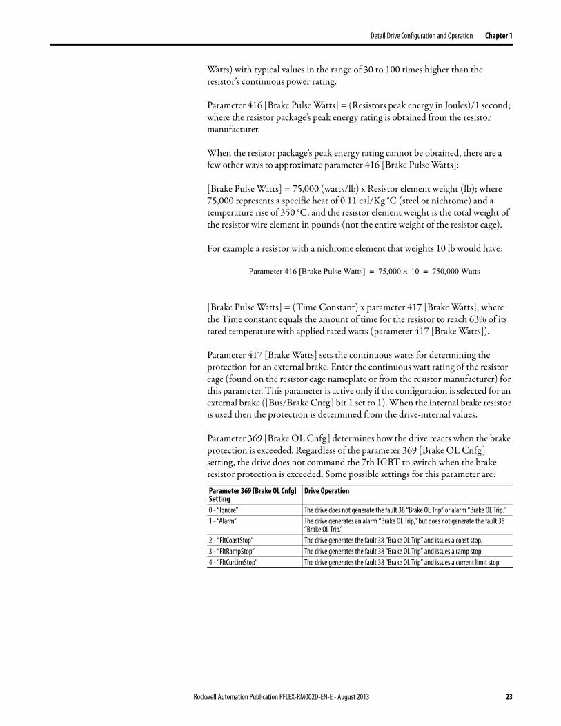
Watts) with typical values in the range of 30 to 100 times higher than the resistor’s continuous power rating.
Parameter 416 [Brake Pulse Watts] = (Resistors peak energy in Joules)/1 second; where the resistor package’s peak energy rating is obtained from the resistor manufacturer.
When the resistor package’s peak energy rating cannot be obtained, there are a few other ways to approximate parameter 416 [Brake Pulse Watts]:
[Brake Pulse Watts] = 75,000 (watts/lb) x Resistor element weight (lb); where 75,000 represents a specific heat of 0.11 cal/Kg °C (steel or nichrome) and a temperature rise of 350 °C, and the resistor element weight is the total weight of the resistor wire element in pounds (not the entire weight of the resistor cage).
For example a resistor with a nichrome element that weights 10 lb would have:
[Brake Pulse Watts] = (Time Constant) x parameter 417 [Brake Watts]; where the Time constant equals the amount of time for the resistor to reach 63% of its rated temperature with applied rated watts (parameter 417 [Brake Watts]).
Parameter 417 [Brake Watts] sets the continuous watts for determining the protection for an external brake. Enter the continuous watt rating of the resistor cage (found on the resistor cage nameplate or from the resistor manufacturer) for this parameter. This parameter is active only if the configuration is selected for an external brake ([Bus/Brake Cnfg] bit 1 set to 1). When the internal brake resistor is used then the protection is determined from the drive-internal values.
Parameter 369 [Brake OL Cnfg] determines how the drive reacts when the brake protection is exceeded. Regardless of the parameter 369 [Brake OL Cnfg] setting, the drive does not command the 7th IGBT to switch when the brake resistor protection is exceeded. Some possible settings for this parameter are:
Parameter 369 [Brake OL Cnfg] Setting
Drive Operation
0 - “Ignore” The drive does not generate the fault 38 “Brake OL Trip” or alarm “Brake OL Trip.”1 - “Alarm” The drive generates an alarm “Brake OL Trip,” but does not generate the fault 38
“Brake OL Trip.”2 - “FltCoastStop” The drive generates the fault 38 “Brake OL Trip” and issues a coast stop.3 - “FltRampStop” The drive generates the fault 38 “Brake OL Trip” and issues a ramp stop.4 - “FltCurLimStop” The drive generates the fault 38 “Brake OL Trip” and issues a current limit stop.
Parameter 416 [Brake Pulse Watts] 75,000 10× 750,000 Watts= =
Rockwell Automation Publication PFLEX-RM002D-EN-E - August 2013 23

Chapter 1 Detail Drive Configuration and Operation
Parameter 418 [Brake TP Sel] selects a value to monitor for diagnostics of the dynamic brake protection. Possible selections for parameter 418 [Brake TP Sel] are:
Parameter 419 [Brake TP Data] displays the data selected in parameter 418 [Brake TP Sel].
Cable, Control See the Wiring and Grounding Guidelines for Pulse Width Modulated (PWM) AC Drives, publication DRIVES-IN001, for detailed information.
Cable, Motor Lengths See the Wiring and Grounding Guidelines for Pulse Width Modulated (PWM) AC Drives, publication DRIVES-IN001, for detailed information.
Cable, Power See the Wiring and Grounding Guidelines for Pulse Width Modulated (PWM) AC Drives, publication DRIVES-IN001, for detailed information.
Cable Trays and Conduit See the Wiring and Grounding Guidelines for Pulse Width Modulated (PWM) AC Drives, publication DRIVES-IN001, for detailed information.
Parameter 418 [Brake TP Sel] Setting
Description
0 - “Zero” Do not monitor any test point for the brake protection.1 - “Duty Cycle” Actual duty cycle of the dynamic brake IGBT where a value of 0 in parameter 419
[Brake TP Data] = full open and 1 = full on.2 - “Power Actual” Actual power applied to the resistor (Watts).3 - “Max BodyTemp” Maximum temperature that the resistor body can handle (°C).4 - “Max ElemTemp Act” Maximum temperature that the resistor element can handle (°C).5 - “BodyTemp Act” Predicted temperature of the resistor body (°C).6 - “ElemTemp Act” Predicted temperature of the resistor element (°C).7 - “BTmpTrip Stat” Maximum resistor body temperature has been exceeded when parameter 419
[Brake TP Data] = 1.8 - “ETmpTripStat” Maximum resistor element temperature has been exceeded when parameter 419
[Brake TP Data] = 1.9 - “Int DB Ohms” Rating of internal resistor when internal resistor is installed (Ohms).10 - “Data State” A value of 0 in parameter 419 [Brake TP Data] = initial state, 1 = internal resistor
data loaded, 2 = external resistor data loaded.11 - “MC BrakeEnbl” A value of 0 in parameter 419 [Brake TP Data] = dynamic braking disabled, 1 =
dynamic braking enabled.12 - “1/rdb” Inverse of the resistance (1/Ohms).13 - “1/th_eb” Inverse of the thermal impedance from the resistor element to body (Watts/°C).14 - “1/ce” Inverse of the resistor element thermal mass (°C/W*s).15 - “tamax” Maximum ambient temperature of resistor (°C).16 - “1/th_ba” Inverse of the thermal impedance from the resistor body to element (Watts/°C).17 - “1/cb” Inverse of the resistor body thermal mass (°C/W*s).18 - “DB IGBT Amp” IGBT current rating (Amps).
24 Rockwell Automation Publication PFLEX-RM002D-EN-E - August 2013

Detail Drive Configuration and Operation Chapter 1
Carrier (PWM) Frequency See the PowerFlex 700S Drives with Phase II Control, Technical Data, publication 20D-TD002, for derating guidelines as they travel to carrier frequency.
Parameter 402 [PWM Frequency] sets the switching frequency. In general, the lowest possible switching frequency that is acceptable for any particular application is the one that should be used. There are several benefits to increasing the switching frequency. Refer to Figure 1 and Figure 2 on page 25. Note the output current at 2 kHz and 4kHz. The “smoothing” of the current waveform continues all the way to 10 kHz.
Figure 1 - Current at 2kHz PWM Frequency
Figure 2 - Current at 4kHz PWM Frequency
The benefits of increased carrier frequency include less motor heating and lower audible noise. An increase in motor heating is considered negligible and motor failure at lower switching frequencies is very remote. The higher switching frequency creates less vibration in the motor windings and laminations making lower audible noise. This may be desirable in some applications. Some undesirable effects of higher switching frequencies include derating ambient temperature vs. load characteristics of the drive, higher cable charging currents and higher potential for common mode noise.
A very large majority of all drive applications will perform adequately at 2…4 kHz.
Rockwell Automation Publication PFLEX-RM002D-EN-E - August 2013 25
Chapter 1 Detail Drive Configuration and Operation
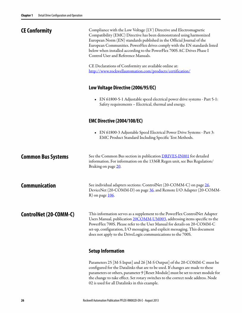
CE Conformity Compliance with the Low Voltage (LV) Directive and Electromagnetic Compatibility (EMC) Directive has been demonstrated using harmonized European Norm (EN) standards published in the Official Journal of the European Communities. PowerFlex drives comply with the EN standards listed below when installed according to the PowerFlex 700S AC Drives Phase I Control User and Reference Manuals.
CE Declarations of Conformity are available online at:http://www.rockwellautomation.com/products/certification/
Low Voltage Directive (2006/95/EC)
• EN 61800-5-1 Adjustable speed electrical power drive systems - Part 5-1: Safety requirements – Electrical, thermal and energy.
EMC Directive (2004/108/EC)
• EN 61800-3 Adjustable Speed Electrical Power Drive Systems - Part 3: EMC Product Standard Including Specific Test Methods.
Common Bus Systems See the Common Bus section in publication DRIVES-IN001 for detailed information. For information on the 1336R Regen unit, see Bus Regulation/Braking on page 20.
Communication See individual adapters sections: ControlNet (20-COMM-C) on page 26, DeviceNet (20-COMM-D) on page 36, and Remote I/O Adapter (20-COMM-R) on page 106.
ControlNet (20-COMM-C) This information serves as a supplement to the PowerFlex ControlNet Adapter Users Manual, publication 20COMM-UM003, addressing items specific to the PowerFlex 700S. Please refer to the User Manual for details on 20-COMM-C set-up, configuration, I/O messaging, and explicit messaging. This document does not apply to the DriveLogix communications to the 700S.
Setup Information
Parameters 25 [M-S Input] and 26 [M-S Output] of the 20-COMM-C must be configured for the Datalinks that are to be used. If changes are made to these parameters or others, parameter 9 [Reset Module] must be set to reset module for the change to take effect. Set rotary switches to the correct node address. Node 02 is used for all Datalinks in this example.
26 Rockwell Automation Publication PFLEX-RM002D-EN-E - August 2013

Detail Drive Configuration and Operation Chapter 1
To use the 20-COMM-C on the PowerFlex 700S with ControlLogix use following setup when adding to the ControlNet device list. Use the values from Table 2 for the input and output sizes. The Configuration Assembly Instance = 6 and Configuration Size = 0.
Table 2 - Node Configuration Input and Output Sizes
The following data structures will be added to the ControlLogix processor for the communications with the 20-COMM-C module and drive.
Node Configured for: Input Size Output SizeLogic Command / Reference and Logic Status / Feedback only 3 2
Plus Datalink A 5 4Plus Datalink B 7 6Plus Datalink C 9 8Plus Datalink D 11 10
Rockwell Automation Publication PFLEX-RM002D-EN-E - August 2013 27

Chapter 1 Detail Drive Configuration and Operation
Example:
Tag names:Outputs to the Drive - PowerFlex700S_02:O[0] … [9]Inputs from the Drive - PowerFlex700S_02:I[0] … [10] word [0] reserved
Figure 3 is an example using Bits in the ControlLogix processor to write to the output bits associated to parameter 158 [Drive Logic Rslt]
PowerFlex700S_02:O[0].0….9 map to parameter 158 [Drive Logic Rslt]
Figure 3 - Using Bits in ControlLogix
Technical Information
To use the 20-COMM-C with the PowerFlex 700S, the 20-COMM-C must be v1.003 firmware or later.
The Logic Command and Logic Status are 32 bit data, but only the first 16 are used. The bit definitions of the Logic Command word follow the same pattern as parameter 158 [Drive Logic Rslt]. The bit definitions of the Logic Status word follow the same pattern as bits 0-15 of parameter 155 [Logic Status].
Reference and Feedback are 16 bit unsigned integer data. Datalinks are 32 bit data. Figure 4 on page 29 shows I/O Image table for a ControlLogix system. I.Data[0] is reserved.
PF700S_Coast Stop
PF700S_CurrLim_Stop
PF700S_Clear_Fault
PF700S_UniPol_Fwd
PF700S_UniPol_Rev
PF700S_Jog2
PF700S_Jog1
PF700S_Start
PF700S_Normal_Stop
PowerFlex700S_02:0.Data[0].1
PowerFlex700S_02:0.Data[0].0
PowerFlex700S_02:0.Data[0].8
PowerFlex700S_02:0.Data[0].7
PowerFlex700S_02:0.Data[0].5
PowerFlex700S_02:0.Data[0].3
PowerFlex700S_02:0.Data[0].2
PowerFlex700S_02:0.Data[0].9
PowerFlex700S_02:0.Data[0].4
28 Rockwell Automation Publication PFLEX-RM002D-EN-E - August 2013

Detail Drive Configuration and Operation Chapter 1
Figure 4 - ControlLogix I/O
1 Bits 0 - 152 Not affected by parameter 73 [Spd Fdbk Scale]
ControlLogix Adapter PowerFlex 700S
Output ImageO.Data[0] DINT
O.Data[1] DINT
O.Data[2] DINT
O.Data[3] DINT
O.Data[4] DINT
O.Data[5] DINT
O.Data[6] DINT
O.Data[7] DINT
O.Data[8] DINT
O.Data[9] DINT
0 Logic Cmd (16-
1 Reference (16
2 Datalink A1
3 Datalink A2
4 Datalink B1
5 Datalink B2
6 Datalink C1
7 Datalink C2
8 Datalink D1
9 Datalink D2
P158 Drive Logic
P20 SpeedRef DPI
P707 Data In A1 Int P708 Data In A1P709 Data In A2 IntP710 Data In A2P711 Data In B1 IntP712 Data In B1P713 Data In B2 Int P714 Data In B2P715 Data In C1 IntP716 Data In C1P717 Data In C2 IntP718 Data In C2 P719 Data In D1 IntP720 Data In D1P721 Data In D2 IntP722 Data In D2
ControlNet DPI
ControlLogix Adapter PowerFlex 700S
Output ImageI.Data[1] DINT
I.Data[2] DINT
I.Data[3] DINT
I.Data[4] DINT
I.Data[5] DINT
I.Data[6] DINT
I.Data[7] DINT
I.Data[8] DINT
I.Data[9] DINT
I.Data[10] DINT
0 Logic Status (16
1 Feedback (16
2 Datalink A1
3 Datalink A2
4 Datalink B1
5 Datalink B2
6 Datalink C1
7 Datalink C2
8 Datalink D1
9 Datalink D2
P158 Drive Logic
P722 SpeedRef DPI
P707 Data In A1 Int P708 Data In A1P709 Data In A2 IntP710 Data In A2P711 Data In B1 IntP712 Data In B1P713 Data In B2 Int P714 Data In B2P715 Data In C1 IntP716 Data In C1P717 Data In C2 IntP718 Data In C2 P719 Data In D1 IntP720 Data In D1P721 Data In D2 IntP722 Data In D2
ControlNet DPI
CIP Generic Message Source and Destination
TagsBuffer
MessageHandler
Message
Rockwell Automation Publication PFLEX-RM002D-EN-E - August 2013 29

Chapter 1 Detail Drive Configuration and Operation
Parameter 723 [Dlink OutDataType] needs to be set for the type of data used. The most common will be Real Data (in other words, Current, Voltage, Torque are all Real values in the drive). The PowerFlex 700S drive default for this parameter is all Datalinks set for Integer values. If the check mark is not set then the datalink is not set for an Integer value (From DriveExecutive).
30 Rockwell Automation Publication PFLEX-RM002D-EN-E - August 2013

Detail Drive Configuration and Operation Chapter 1
ControlLogix Programming
To setup the PowerFlex 700S drive to follow a speed reference from the 20-COMM-C, parameter 691 [DPI Ref Select] must be set to “Port 5.” Parameter 16 [Speed Ref Sel] must be set to “Speed Ref DPI.”
Reference and Feedback values are floating-point values in the PowerFlex 700S. Use the following logic to transmit and receive reference and feedback data as unsigned integer data.
Reference to 700S (Commanded RPM Base Motor Speed)⁄
32767------------------------------------------------------------------------------------------------------=
MOV
CPT
MOV
Speed Reference Via ControlNet to a PowerFlex 700S using a 20-COMM-C module.
The first move instruction is only for visual indication of the speed reference.
MoveSource CNet_Ref_RPM 1200.0Dest CNet_Ref_RPM 1200.0
ComputeDest CNet_700S_Ref_Float 22114.959 Expression (CNet_Ref_RPM/Motor_Base_Speed)*Speed_Conversion_Constant
MoveSource CNet_Ref_Float 22114.959 Dest PowerFlex700S_02:0.Data(1) 22115
Feedback RPM (700S Feedback 32767) Base Motor Speed×⁄=
CPT
MOV
Convert Speed Feedback from 700S via 20-COMM-CFeedback is returned as a 0 to 32767 number for 0 to Base Speed
ComputeDest CNet_700S_Fdbk 1897Expression (CNet_700S_Fdbk_Float/Speed_Conversion_Constant)*Motor_Base_Speed
MoveSource PowerFlex700S_02:1.Data[2] 22114.959 Dest CNet_700S_Fdbk_Float 34969.0
Rockwell Automation Publication PFLEX-RM002D-EN-E - August 2013 31

Chapter 1 Detail Drive Configuration and Operation
Datalink Programming
In the ControlLogix system, Datalinks are transmitted over ControlNet as 32 bit integers (DINT). In order to send or receive floating point a COP (copy) instruction must be utilized. The copy instruction in ControlLogix performs a bitwise copy. Set the length of the copy instruction to a value appropriate for the destination data type. For example, when copying a DINT data type to a REAL data type, the length would be one since both data types contain 32 bits of data.
Figure 5 is for all Datalinks selected.
Figure 5 - All Datalinks Selected
Explicit Messaging
When using explicit messaging in the ControlLogix system, the message type CIP Generic is used. The data is transferred over ControlNet in the same data type as the parameter in the PowerFlex 700S. Make sure the data type for the Source and Destination tags in your ControlLogix message instruction matches the data type in the PowerFlex 700S. Also, the Number of Elements in the ControlLogix message instruction must match the size of the Source data.
For example, to send an explicit message to write to parameter 12 [Speed Ref 2], which is a floating point:
1. The Source and Destination tags should be of type REAL.
2. The Number of Elements should be 4 bytes since a REAL data type takes up 4 bytes of data.
COP
Copy data from ControlLogix Processor to 20-COMM-C for 700S Data Links
Copy FileSource PF700_Float_Data[10]Dest PowerFlex700S_02:O.Data[2] Length 8
COPCopy FileSource PowerFlex700S_02:I.Data[3]Dest PF700_Float_Data[0] Length 8
Copy data from 20-COMM-C to Floating Point data file.Parameter 723 must be set to real data links on the 700S
32 Rockwell Automation Publication PFLEX-RM002D-EN-E - August 2013

Detail Drive Configuration and Operation Chapter 1
For other types of messages refer to the 20-COMM-C user manual.
Copy Cat This feature allows you to upload a complete set of parameters to the LCD HIM. This information can then be used as backup or can be transferred to another drive by downloading the memory. Generally, the transfer process manages all conflicts. If a parameter from HIM memory does not exist in the target drive, the value stored is out of range for the drive, or the parameter cannot be downloaded because the drive is running, the download will stop and a text message will be issued. The user than has the option of completely stopping the download or continuing after noting the discrepancy for the parameter that could not be downloaded. These parameters can then be adjusted manually. The LCD HIM will store a number of parameter sets (memory dependant) and each individual set can be named for clarity.
Current Limit The following methods are available for a drive to use to protect itself from an overcurrent or overload condition.
Instantaneous Over Current Trip - This is a feature that instantaneously trips or faults the drive if the output current exceeds this value. The value is fixed by hardware and is typically 250% of drive rated amps. This feature cannot be disabled.
Software Over Current Trip - This is a configurable trip function. If parameter 377 [Inv OL Trip Cnfg] is set to Fault Coast to Stop, the drive will trip on inverter overload. This will occur when the Open Loop or Closed Loop IT function has detected an overload condition. See the Drive Overload on page 48 section for a description of the Open Loop and Closed Loop IT functions.
Software Current Limit - This feature selectively limits the current the drive will provide based on the several factors. The [Mtr Current Lim] parameter setting will limit the current to the user changeable level, range is 105% of Motor Flux
Rockwell Automation Publication PFLEX-RM002D-EN-E - August 2013 33

Chapter 1 Detail Drive Configuration and Operation
Current to 800% of the motor nameplate entered in 2 [Motor NP FLA]. The Open Loop IT function can also limit the output current if the calculation determines it is in the overload area of operation. The Open Loop IT function and the Motor Current Limit parameters are routed to a minimum selection, the algebraic minimum of the inputs is used as the current limit. Also, the Closed Loop IT function can limit the current output by the drive. The Closed Loop IT function and the Torque Current Reference are compared and the algebraic minimum is used for the Torque Current Reference. See the Drive Overload on page 48 section for a description of the Open Loop and Closed Loop IT Functions.
Datalinks Datalinks are used to transfer I/O data from a communication adapter, such as ControlNet (20-COMM-C) or DeviceNet (20-COMM-D), to a controller. Datalinks allow parameter values to be changed without using messaging.
Configuring Datalinks
This section contains information on configuring the Datalink parameters for the PowerFlex 700S. There are also parameters in the communication adapters that must be configured to use Datalinks. Refer to the ControlNet (20-COMM-C) on page 26 and DeviceNet (20-COMM-D) on page 36 sections for more information.
“Data In” Parameters
[Data In x Int] and [Data In x Real] parameters are inputs to the drive from the controller and are used to write to parameters. A total of 8 parameters can be written with the “Data In” parameters. In the 700S, each parameter is either a 16 bit integer, a 32 bit integer or a 32 bit floating point (real). This means the datalinks parameters are 32 bits.
To write to a 16 bit or 32 bit integer parameter, that parameter must be linked to one of the [Data In x Int] parameters.
To write to a real parameter, that parameter must be linked to one of the [Data In x Real] parameters.
Example Configuration 1:
Writing an Integer parameter using a Datalink:
• 740 [Position Control] is linked to 707 [Data In A1 Int]
The value that is sent to [Data In A1 Int] from the controller will show up in [Postion Control]. [Data In A1 Int] is used because [Position Control] is an integer parameter.
34 Rockwell Automation Publication PFLEX-RM002D-EN-E - August 2013

Detail Drive Configuration and Operation Chapter 1
Example Configuration 2:
Writing a Real Parameter using a Datalink:
• 111 [Torque Ref 1] is linked to 708 [Data In A1 Real]
The value that is sent to [Data In A1 Real] from the controller will show up in [Torque Ref 1]. [Data In A1 Real] is used because [Torque Ref 1] is a real integer parameter.
“Data Out” Parameters
[Data Out x Int] and [Data Out x Real] parameters are outputs from the drive to the controller and are used to read parameters. A total of 8 parameters can be read with the “Data Out” parameters. In the 700S, each parameter is either a 32 bit integer or a 32 bit floating point (real). This means that the datalink parameters are 32 bits. Parameter 723 [Dlink OutDataTyp] is used to select whether each of the 8 “Data Out” data is an integer or real.
To read a 16 bit or 32 bit integer parameter, one of the [Data Out x Int] parameters must be linked to the desired integer parameter. Then the bit corresponding to the [Data In x Int] parameter in [Dlink OutDataType] is set to 0.
To read to a real parameter, one of the [Data Out x Real] parameters must be linked to the desired real parameter. Then bit corresponding to the [Data Out x Real] parameter in [Dlink OutData Type] is set to 1.
Example Configuration 3:
Reading an Integer Parameter Using a Datalink
• 724 [Data Out A1 Int] is linked to 741 [Position Status]
• 723 [Dlink OutData Type] bit 0 is set to 0
The value from [Data Out A1 Int] to the controller contains the value of [Position Status]. [Data Out A1 Int] is used and [Dlink OutDataType] bit 0 is set to 0 because [Position Status] is an integer parameter.
Example Configuration 4:
Reading a Real Parameter using a Datalink
• [Data Out A1 Real] is linked to [Output Current]
• [Dlink OutDataType] bit 1 is set to 1
The value from [Data Out A1 Real] to the controller contains the value of [Output Current]. [Data Out A1 Real] is used and [Dlink OutDataType] bit 0 is set to 1 because [Output Current] is a real parameter.
Rockwell Automation Publication PFLEX-RM002D-EN-E - August 2013 35
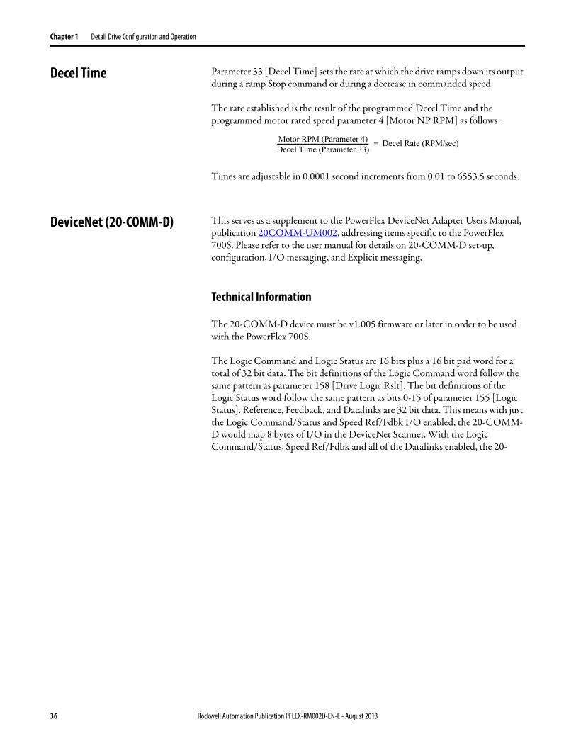
Chapter 1 Detail Drive Configuration and Operation
Decel Time Parameter 33 [Decel Time] sets the rate at which the drive ramps down its output during a ramp Stop command or during a decrease in commanded speed.
The rate established is the result of the programmed Decel Time and the programmed motor rated speed parameter 4 [Motor NP RPM] as follows:
Times are adjustable in 0.0001 second increments from 0.01 to 6553.5 seconds.
DeviceNet (20-COMM-D) This serves as a supplement to the PowerFlex DeviceNet Adapter Users Manual, publication 20COMM-UM002, addressing items specific to the PowerFlex 700S. Please refer to the user manual for details on 20-COMM-D set-up, configuration, I/O messaging, and Explicit messaging.
Technical Information
The 20-COMM-D device must be v1.005 firmware or later in order to be used with the PowerFlex 700S.
The Logic Command and Logic Status are 16 bits plus a 16 bit pad word for a total of 32 bit data. The bit definitions of the Logic Command word follow the same pattern as parameter 158 [Drive Logic Rslt]. The bit definitions of the Logic Status word follow the same pattern as bits 0-15 of parameter 155 [Logic Status]. Reference, Feedback, and Datalinks are 32 bit data. This means with just the Logic Command/Status and Speed Ref/Fdbk I/O enabled, the 20-COMM-D would map 8 bytes of I/O in the DeviceNet Scanner. With the Logic Command/Status, Speed Ref/Fdbk and all of the Datalinks enabled, the 20-
Motor RPM (Parameter 4)
Decel Time (Parameter 33)----------------------------------------------------------------- Decel Rate (RPM/sec)=
36 Rockwell Automation Publication PFLEX-RM002D-EN-E - August 2013

Detail Drive Configuration and Operation Chapter 1
COMM-D would have a total of 40 bytes of I/O mapped in the DeviceNet scanner. The I/O Image table for a ControlLogix system is shown.
1 The speed reference comes into the 20-COMM-D as a double integer. The PowerFlex 700S firmware automatically converts that speed reference into floating point, so that parameter 20 [Speed Ref DPI] is a floating-point value.
1 Bits 0-15 only of parameter 155 [Logic Status] appear in the Input Image table of the ControlLogix controller.2 The speed feedback sent from the PowerFlex 700S to the 20-COMM-D is not affected by parameter 73 [Spd Fdbk Scale].
Furthermore, the PowerFlex 700S automatically coverts parameter 72 [Scaled Spd Fdbk], which is a floating-point parameter, to a double integer before the value is transferred to the 20-COMM-D.
ControlLogix Adapter PowerFlex 700S
Output ImageO.Data[0] DINT
O.Data[1] DINT
O.Data[2] DINT
O.Data[3] DINT
O.Data[4] DINT
O.Data[5] DINT
O.Data[6] DINT
O.Data[7] DINT
O.Data[8] DINT
O.Data[9] DINT
0 Logic Command 1 Pad Word2 Reference3 Reference4 Datalink A15 Datalink A16 Datalink A27 Datalink A28 Datalink B19 Datalink B11 Datalink B21 Datalink B21 Datalink C11 Datalink C1 1 Datalink C2 1 Datalink C2 1 Datalink D1 1 Datalink D1 1 Datalink C2 1 Datalink C2
P158 Drive Logic
P20 SpeedRef DPI
P707 Data In A1 Int P708 Data In A1P709 Data In A2 IntP710 Data In A2P711 Data In B1 IntP712 Data In B1713 Data In B2 Int P714 Data In B2P715 Data In C1 IntP716 Data In C1P717 Data In C2 IntP718 Data In C2 P719 Data In D1 IntP720 Data In D1P721 Data In D2 IntP722 Data In D2
DPIDeviceNet
1
ControlLogix Adapter PowerFlex 700S
Input ImageI.Data[0] DINT
I.Data[1] DINT
I.Data[2] DINT
I.Data[3] DINT
I.Data[4] DINT
I.Data[5] DINT
I.Data[6] DINT
I.Data[7] DINT
I.Data[8] DINT
I.Data[9] DINT
0 Logic Status 1 Pad Word2 Feedback (LSW) 3 Feedback4 Datalink A15 Datalink A16 Datalink A27 Datalink A28 Datalink B19 Datalink B11 Datalink B21 Datalink B21 Datalink C11 Datalink C11 Datalink C21 Datalink C21 Datalink D11 Datalink D11 Datalink D21
P1551 Logic Status
P72 Speed Ref DPI
P724 Data Out A1 P725 Data Out A1P726 Data Out A2 P727 Data Out A2P728 Data Out B1 P729 Data Out B1P730 Data Out B2 P731 Data Out B2P732 Data Out C1 P733 Data Out C1P734 Data Out C2 P735 Data Out C2 P736 Data Out D1 P737 Data Out D1P738 Data Out D2 P739 Data Out D2
CIP Generic MessageSource and Destination
Tags
MessageBuffer
MessageHandler
2
DPIDeviceNet
Rockwell Automation Publication PFLEX-RM002D-EN-E - August 2013 37

Chapter 1 Detail Drive Configuration and Operation
To setup the PowerFlex 700S to follow a speed reference from the 20-COMM-D, Parameter 691 [DPI Ref Select] must be set to “Port 5.” Parameter 16 [Speed Ref Sel] must be set to “Speed Ref DPI.”
Reference and Feedback values are floating-point values in the PowerFlex 700S. Use the following logic to transmit and receive reference and feedback data as integer data.
In the ControlLogix system, Datalinks are transmitted over DeviceNet as 32 bit integers (DINT). In order to send or receive floating point a COP (copy) instruction must be used. The copy instruction in ControlLogix performs a bitwise copy. Set the length of the copy instruction to a value appropriate for the destination data type. For example, when copying a DINT data type to a REAL data type, the length would be one (1) since both data types contain 32 bits of data.
When using explicit messaging in the ControlLogix system, the message type CIP Generic is used. The data is transferred over DeviceNet in the same data type as the parameter in the PowerFlex 700S. Make sure that the data type for the Source and Destination tags in your ControlLogix message instruction matches the data type in the PowerFlex 700S. Also, the Number of Elements in the ControlLogix message instruction must match the size of the Source data. For example, to send an explicit message to write to parameter12 [Speed Ref 2], which is floating point:
• The Source and Destination tags should be type REAL.
• The Number of Elements should be 4 bytes since a REAL data type takes up 4 bytes of data.
Transmitted ReferenceFloating Point Reference (RPM) 32768×
Base Motor RPM----------------------------------------------------------------------------------------------------=
Floating point Feedback (RPM)Feedback received Base Motor RPM×
32768----------------------------------------------------------------------------------------------=
38 Rockwell Automation Publication PFLEX-RM002D-EN-E - August 2013

Detail Drive Configuration and Operation Chapter 1
SLC/PLC-5 System
Reference/Feedback Programming
The reference is scaled so that base motor speed = 32768. The SLC/PLC-5 does not use DINT, and only handles 16 bit integers, so the reference has to be handled differently to account for references above 32767 or below -32768. The example on the following page shows how to transmit references less than twice base motor speed.
Rockwell Automation Publication PFLEX-RM002D-EN-E - August 2013 39

Chapter 1 Detail Drive Configuration and Operation
The feedback is also scaled so that base motor speed = 32768. The SLC/PLC-5 does not use DINT, and only handles 16 bit integers, so the feedback has to be handled differently to account for references above 32767 or below -32768. The following example shows how to read feedback values less than twice base motor speed.
Datalink Programming
Datalinks are transmitted and received through block transfer I/O. The SLC/PLC-5 is limited to 16 bit integers and floating point. Because the SLC/PLC-5 does not support 32-bit integers, 32-bit integer datalinks remain split into two, 16 bit integers. In order to send or receive floating-point datalinks the LSW and MSW must be swapped and the COP (copy) instruction must be utilized. The following examples are for transmitting and receiving the floating-point Datalinks.
40 Rockwell Automation Publication PFLEX-RM002D-EN-E - August 2013
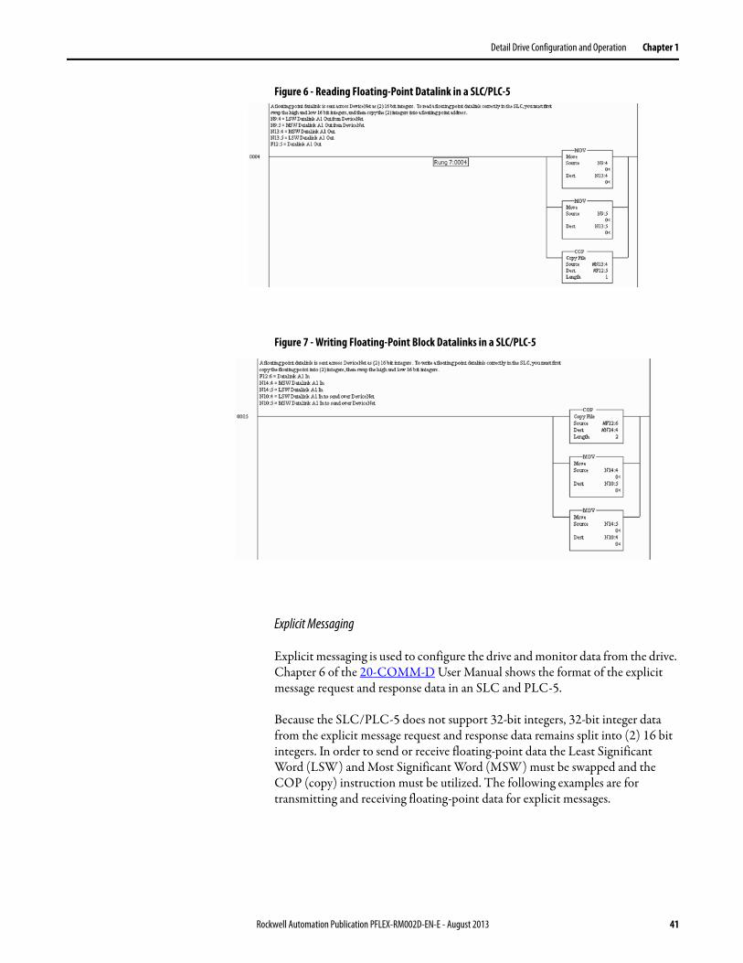
Detail Drive Configuration and Operation Chapter 1
Figure 6 - Reading Floating-Point Datalink in a SLC/PLC-5
Figure 7 - Writing Floating-Point Block Datalinks in a SLC/PLC-5
Explicit Messaging
Explicit messaging is used to configure the drive and monitor data from the drive. Chapter 6 of the 20-COMM-D User Manual shows the format of the explicit message request and response data in an SLC and PLC-5.
Because the SLC/PLC-5 does not support 32-bit integers, 32-bit integer data from the explicit message request and response data remains split into (2) 16 bit integers. In order to send or receive floating-point data the Least Significant Word (LSW) and Most Significant Word (MSW) must be swapped and the COP (copy) instruction must be utilized. The following examples are for transmitting and receiving floating-point data for explicit messages.
Rockwell Automation Publication PFLEX-RM002D-EN-E - August 2013 41

Chapter 1 Detail Drive Configuration and Operation
Figure 8 - Reading Floating-Point Explicit Message Data in an SLC/PLC-5
Figure 9 - Writing Floating-Point Explicit Message Data in an SLC/PLC-5
Digital Inputs Technical Information
There are four digital inputs on the I/O board. One of the inputs is dedicated for the Enable and cannot be configured. The other three inputs can be configured. Digital Input 1 is 24VDC and Digital Inputs 2 and 3 can accept a 12…24VDC signal. There is a 24VDC power supply on the I/O board to supply power for those inputs.
Digital Inputs 2 and 3 are high speed digital inputs with a maximum input frequency of 350 kHz.
42 Rockwell Automation Publication PFLEX-RM002D-EN-E - August 2013

Detail Drive Configuration and Operation Chapter 1
Figure 10 - Digital Input Configuration
[DigIn 1 Sel] can be set to the following values:
826
827
BitCombine
828
DigIn1 User DataLocal I/O Status
(DigIn 1)
DigIn1 Data
DigIn1 Bit
838
Selector
0101
DigIn 1 Sel
830
831
BitCombine
836
DigIn2 User DataLocal I/O Status
(DigIn 2)
DigIn2 Data
DigIn2 Bit
840
Selector
824 02824 02
DigIn 2 SelSelections per Par 839
TB1-T10
TB1-T11
24 VDC
24 VDC Common
Debounce
Debounce
{Logic Common}
824 00Local I/O Status (Enable In)
En In Debounce
TB1-T9
TB1-T8
TB1-T7DigIn 1 Debounce
Debounce
TB1-T5
TB1-T6
Bit Filter
236
SyncLink
08
09
10
11
DigIn 2 Debounce
{Return "Common"}
Port0 Regis
(Ext Filt 0)
(Ext Filt 1)
Cnfg
(Ext Filt 3)
(Ext Filt 2)
236
236
236
833
825
829
Debounce
TB1-T3
TB1-T4
Bit Filter
SyncLink
DigIn 3 Debounce
{Return "Common"}
837834
835
BitCombine
836
DigIn3 User Data
DigIn3 Data
DigIn3 Bit
840
Selector
824 03
246 08
09
10
11
Port0 Regis
(Ext Filt 0)
(Ext Filt 1)
Cnfg
(Ext Filt 3)
(Ext Filt 2)
246
246
246
824 03
DigIn 3 SelSelections per Par 840
824 824
Value Description Value Description
0 Not Used 8 Fwd/Reverse
1 Normal Stop 9 Cur Lim Stop
2 Start 10 Coast Stop
3 Run 11 Aux Fault
4 Clear Faults 12 Aux Fault Inv
5 Stop - CF 13 User Select
6 Jog 1 14 Precharge/Disc
7 Jog 2
Rockwell Automation Publication PFLEX-RM002D-EN-E - August 2013 43

Chapter 1 Detail Drive Configuration and Operation
[DigIn 2 Sel] can be set to the following values:
[DigIn 3 Sel] can be set to the following values:
[DigIn x Debounce] sets a delay time to allow any bounce in the digital input to settle out. This parameter has a range of 0 to 15.5 milliseconds.
When [DigIn x Sel] is set to “User Select,” the function of the digital input is determined by the following:
• [DigIn x Data] determines any bits that should be permanently set. [DigIn x Data] sets the value of [DigIn x User Data] except for the bit chose in [DigIn x Bit]
• [DigIn x Data] determines the bit you wish to toggle based on whether the digital input is on or off
Value Description Value Description
0 “Not Used” 14 “Normal Stop”
1 “Enable” 15 “Spd Ref Sel1”
2 “Clear Faults” 16 “Spd Ref Sel2”
3 “Ext Fault” 17 “Spd Ref Sel3”
4 “Norm Stop-CF” 18 “CurLim Stop”
5 “Start” 19 “Coast Stop”
6 “Reverse” 21 “BscIndx Step”
7 “Run” 22 “BscIndxStpRv”
8 “Fwd/Reverse” 26 “PI Trim En”
9 “CurLim Stop” 29 “Trend Trig”
10 “Jog 1” 30 “PreCharge En”
11 “Aux Fault” 31 “Regis 1 Ltch”
12 “AuxFault Inv” 32 “+Hrd OvrTrvl”
13 “Jog 2” 33 “-Hrd OvrTrvl”
Value Description Value Description
0 “Not Used” 9 “CurLim Stop”
1 “Normal Stop” 10 “Coast Stop”
2 “Start” 11 “Aux Fault”
3 “Run” 12 “AuxFault Inv”
4 “Clear Faults” 13 “User Select”
5 “Stop-CF” 23 “Logix Motion”
6 “Jog 1” 24 “+Hrd OvrTrvl”
7 “Jog 2” 25 “-Hrd OvrTrvl”
8 “Fwd/Reverse”
44 Rockwell Automation Publication PFLEX-RM002D-EN-E - August 2013

Detail Drive Configuration and Operation Chapter 1
• [DigIn x User Data] will have the same bits that are set in [DigIn x Data]. Then the bit that was chosen in [Digin x Bit] will toggle based on whether the digital input is on or off. A designation (sink) parameter is then linked to [DigIn x User Data] so that it determines the value of that sink parameter
Configuration Example
DigIn 1 will be setup to determine the value of [Speed Ref Sel]. DigIn 1 will toggle [Speed Ref Sel] between a value of 1 “Speed Ref 1” and 5 “Speed Ref 5.”
• [DigIn 1 Sel] = “User Select”
• [DigIn 1 Data] = 0000 0000 0000 0000 0000 0000 0000 0001
• [DigIn 1 Bit] = 2. This means when we toggle Digital Input 1, bit 2 of [DigIn 1 User Data] will toggle.
When Digital Input 1 is off [DigIn 1 User Data] will be equal to [DigIn 1 Data]. In other words, [DigIn 1 User Data] will equal 0000 0000 0000 0000 0000 0000 0000 0001 (a value of 1).
When Digital Input 1 is on [DigIn 1 User Data] will be equal to [DigIn 1 Data] plus whatever bit was set in [DigIn 1 Bit]. In other words [DigIn 1 User Data] will equal 0000 0000 0000 0000 0000 0000 0000 0101 (a value of 5).
[Speed Ref Sel] is linked to [DigIn 1 User Data]. Now [Speed Ref Sel] will toggle between a value of 1 and 5.
Digital Input Status Bits
[Local I/O Status], bits 0…4 indicate the status of the digital inputs and can be used for troubleshooting the digital inputs. The bits are broken down as follows:
• Bit 0 - “Enable Input”• Bit 1 - “Digital Input 1”• Bit 2 - “Digital Input 2”• Bit 3 - “Digital Input 3”
When the bit in [Local I/O Status] associated with the digital input is set (=1), the digital input is on. When the bit associated with the digital input is not set (=0), the digital input is off.
Rockwell Automation Publication PFLEX-RM002D-EN-E - August 2013 45

Chapter 1 Detail Drive Configuration and Operation
Digital Outputs Technical Information
There are three digital outputs on the I/O board.
Digital Outputs 1 and 2 are 24VDC open collector (sinking logic). They are rated 25 mA maximum. Figure 11 - is an example of how Digital Outputs 1 and 2 would be used with a light.
Note: The transistor in the diagram is the internal circuitry of the Digital Output. When the logic for Digital Output 1 becomes true, the transistor turns on, tying the transistor's collector to ground and completing the circuit. Then the light will turn on.
Figure 11 - Digital Outputs
Digital Output 3 is a relay output rated for 24VDC. The relay output is rated 5 A at 24VDC for a resistive load, and 2 A at 24VDC for an inductive load.
Figure 12 - Digital Output Configuration
Digital Output
Common (Return)
T6Sinking Ouput
G + 24V DC
Digital Output
Logic
T4
841
842
Relay Out Data
Relay Out Bit
16 Local I/O Status(Output Relay)
TB2-B5
TB2-B4
843
844
Dig Out 1 Data
Data Out 1 Bit
17 Local I/O Status(Aux Out 1)
TB1-T6
TB1-T5
845
846
Dig Out 2 Data
Data Out 2 Bit
Local I/O Status(Aux Out 2)18
TB1-T4
{Return "Common"}
824
824
824
46 Rockwell Automation Publication PFLEX-RM002D-EN-E - August 2013

Detail Drive Configuration and Operation Chapter 1
The [Relay x Data] parameter and [Dig Out x Data] parameters are linked to a parameter used to turn on the digital output.
The [Relay x Bit] parameter and [Dig Out x Bit] parameters select which bit of the data you wish to use to turn on the digital output.
Configuration Example
This example configures Digital Output 1 for “Enabled.” “Enabled” indicates the inverter section of the drive is active (IGBTs switching).
• [Dig Out 1 Data] is linked to [Logic Status]
• [Dig Out 1 Bit] is set to 0
When the “Enabled” bit of [Logic Status] turns on, Digital Output 1 turns on.
Digital Output Status Bits
[Local I/O Status], bits 16…18 indicate the status of the digital outputs and can be used for troubleshooting the digital outputs. The bits are broken down as follows:
• Bit 16 - “Digital Output 3” (Output Relay)
• Bit 17 - “Digital Output 1” (Aux Out 1)
• Bit 18 - “Digital Output 2” (Aux Out 2)
When the bit in [Local I/O Status] associated with the digital output is set (=1), the digital output is turned on. When the bit associated with the digital output is not set (=0), the digital output is turned off.
Direction Control and Bipolar Reference
The direction of rotation of the motor can be controlled by a forward/reverse command or by the use of a bipolar signal. Parameter 153 [Control Options] bit 0 - “Bipolar Sref ” selects this option.
When this bit is enabled (1) a bipolar speed reference is used. In bipolar reference mode, Par 40 [Selected Spd Ref ] indicates both the speed magnitude and the direction: Positive speed reference values (+) = forward direction and negative speed reference values (–) = reverse direction. When this bit is disabled a unipolar speed reference is used. In unipolar mode, the speed reference is limited to a minimum value of zero (0), shown by the Max selection block (as shown in the diagram below). In this case Par 40 [Selected Spd Ref ] supplies only the speed magnitude. The direction is determined by Par 153 [Applied LogicCmd] bits 20 “UniPol Fwd” and 21 “UniPol Rev”. The forward/reverse direction
Rockwell Automation Publication PFLEX-RM002D-EN-E - August 2013 47

Chapter 1 Detail Drive Configuration and Operation
button on the HIM is one possible source for the [Applied Logic Command] direction bits. The following chart explains the effect that the direction button on the HIM has based on the condition of the “Bipolar SRef ” bit:
In either Bipolar or Unipolar mode, the selected direction can be determined from the sign of Par 41 [Limited Spd Ref ]. Positive values indicate forward rotation and negative values indicate reverse rotation.
Drive Overload Theory of Operation
The following discussion assumes that the IT curve does not change with Pulse Width Modulated (PWM) carrier frequency or drive output frequency.
A drive has three rated current values; a continuous current rating, a 1 minute current rating, and a 3 second current rating. Typically, the 1 minute rating will be close to 110% of the continuous rating, and the 3 second rating will be close to 150% of the continuous rating. This may vary from drive to drive to optimize the performance of each frame size. In the following examples the 1 minute rating is 110% and the 3 second rating is 150%.
Open Loop Current Limit
The drive can thermally allow 102.5%.
The 1 minute current rating assumes a duty cycle of 1 minute on, followed by 3 minutes at 100%. This results in an average current of 102.5%.
Bipolar Reference Controlled By HIM? HIM Direction Button
Enabled Yes Changes the motor direction due to a HIM supplied (+) or (-) command signal.
Enabled No Has no effect on motor direction. Direction determined by sign of Par 40 [Selected SpdRef].
Disabled Yes Changes the motor direction due to a HIM supplied forward or reverse [Applied LogicCmd] bit.
Disabled No Changes the motor direction due to a HIM supplied forward or reverse [Applied LogicCmd] bit.
0
153 00
Max X
1
1
152
Control Options
(Unipol Fwd) +1
(Unipol Rev) -1
20 152 21
1
0
40
Selected Spd Ref
Applied Logic Cmd
110% * 60 s + 100%*180 s
240 s
average current = ------------------------------------------- = 102.5%
48 Rockwell Automation Publication PFLEX-RM002D-EN-E - August 2013

Detail Drive Configuration and Operation Chapter 1
The 3 second current rating assumes a duty cycle of 3 seconds on, followed by 57 seconds at 100%. This results in an average current of 102.5%.
Typically the drive will have a 60 second rating of 110% of continuous current and a 3 second rating at 150% of the continuous current. Under normal operating conditions, the open loop function sets this current limit to the short term (three-second) rating. If the function detects an overload, it lowers the limit to the continuous level. If the function is in the continuous level limit, this can be lower than the Motor Current limit. After a period of time (typically one to three minutes), the function returns the limit to the short term rating.
Closed Loop IT Function
The drive will also adjust the Torque Current limit level based on the values in Parameter 358 [Iq Ref Limited], parameter 313 [Heatsink Temp] and the thermal characteristics of the drive contained in the power EE memory. Under normal operating conditions, the function typically sets the limit at 250% of the continuous drive rating. If the function determines that the power device junction temperature is approaching maximum, it will reduce this limit to the level required to prevent additional heating of the inverter. This level could be as low as the continuous rating of the drive output amps. If the inverter temperature decreases, the function will raise the limit to a higher level.
Drive Overload Status
Drive Overload Status can be monitored in parameter 346 [Drive OL Status].• Bit 0 [NTC Shorted] indicates the Negative Temperature Coefficient
(NTC) device has a short circuit.• Bit 1 [NTC Open] indicates the NTC has an open circuit.• Bit 2 [HS OverTemp] indicates heatsink temperature is above: 105 °C for
ratings 1.1…11.0A, 115 °C for 14…34A, 100 °C for 40…52A.• Bit 3 [HS Pending] indicates heatsink temperature is above: 95 °C for
ratings 1.1…11A, 105 °C for 14…34A, 90 °C for 40…52A.• Bit 4 [IT Trip] indicates the drive has exceed the 3 second rating of either
the 150% normal duty rating or 200% of the heavy duty rating.• Bit 5 [IT Pending] indicates the drive OL integrator is at 50% of the time
out time.• Bit 6 [IT Foldback] indicates the drive closed loop current limit is in a fold
back condition. The value of the fold back is proportional to the calculated junction temperature.
• Bit 7 [Jnc Over Temp] indicates the junction temperature has exceeded the maximum temperature for the power semiconductor device.
150% * 3 s + 100%*57 s
60 s
average current = ------------------------------------------- = 102.5%
Rockwell Automation Publication PFLEX-RM002D-EN-E - August 2013 49

Chapter 1 Detail Drive Configuration and Operation
Drive Overtemperature(Frame 9 Only)
The drive overtemperature is 90 °C. The fault is detected if the heat-sink temperature, parameter 313 [Heatsink Temp] or parameter 345 [Drive OL JnctTmp] exceeds 90 °C.
The open loop current limit is originally designed for 25% of the duty cycle at 110% output current. On the other side, the High Horsepower drive allows 10% of duty cycle at 110% output current. The open loop current limit function can not protect the drive overtemperature fault.
Drive Peripheral Interface (DPI)
DPI is an enhancement to SCANport that provides more functions and better performance. SCANport was a CAN based, Master-Slave protocol, created to provide a standard way of connecting motor control products and optional peripheral devices together. It allows multiple (up to 6) devices to communicate with a motor control product without requiring configuration of the peripheral. SCANport and DPI both provide two basic message types called Client/Server (C/S) and Producer/Consumer (P/C). C/S messages are used to transfer parameter and configuration information in the background (relative to other message types). P/C messages are used for control and status information. DPI adds a higher baud rate, brand specific enabling, Peer-to-Peer (P/P) communication, and Flash Memory programming support. This communication interface is the primary way to interact with, and control the drive.
Client/Server
C/S messages operate in the background (relative to other message types) and are used for non-control purposes. The C/S messages are based on a 10 ms “ping” event that allows peripherals to perform a single transaction (i.e. one C/S transaction per peripheral per time period). Message fragmentation (because the message transaction is larger than the standard CAN message of eight data bytes) is automatically handled by C/S operation. The following types of messaging are covered:
• Logging in peripheral devices • Read/Write of parameter values• Access to all parameter information (limits, scaling, default, etc.)• User set access• Fault/Alarm queue access• Event notification (fault, alarm, etc.)• Access to all drive classes/objects (for example Device, Peripheral,
Parameter, etc.)
IMPORTANT The PowerFlex 700S only supports the DPI communication protocol.The PowerFlex 700S will not communicate with SCANport devices.The PowerFlex 700S does not support LED HIMs.
50 Rockwell Automation Publication PFLEX-RM002D-EN-E - August 2013

Detail Drive Configuration and Operation Chapter 1
Producer/Consumer Operation Overview
P/C messages operate at a higher priority than C/S messages and are used to control/report the operation of the drive (for example start, stop, etc.). A P/C status message is transmitted every 5 ms (by the drive) and a command message is received from every change of state in any attached DPI peripheral. Change of state is a button being pressed or error detected by a DPI peripheral. P/C messages are of a fixed size, so support of message fragmentation is not required. The following types of messaging are covered:
• Drive status (running, faulted, etc.)• Drive commands (start, stop, etc.)• Control logic parsing operations (for example, mask and owner
parameters)• Entering Flash programming mode• “Soft” login and logout of peripheral devices (enabling/disabling of
peripheral control)
Peer-to-Peer Operation
Peer-to-Peer messaging allows two devices to communicate directly rather than through the master or host (i.e. drive). They are the same priority as C/S messages and will occur in the background. If an LCD HIM is attached to the PowerFlex 700S drive, it will be able to directly request off-board parameters using Peer-to-Peer messages (i.e. no proxy support needed in the drive). PowerFlex 700S drives can use all six communication ports because Peer-to-Peer proxy operations are not needed. All Peer-to-Peer operations occur without any intervention from the user (regardless whether proxy or normal P/P operation), no setup is required. No Peer-to-Peer proxy operations are required while the drive is in Flash mode.
All the timing requirements specified in the DPI system, Control, and Messaging specifications are supported. Peripheral devices will be scanned (“pinged”) at a 10ms rate. Drive status messages will be produced at a 5 ms rate, while peripheral command messages will be accepted (by the drive) as they occur (i.e. change of state). Based on these timings, the following worst case conditions can occur (independent of the baud rate and protocol):
• Change of peripheral state (for example, Start, Stop, etc.) to change in the drive - 10 ms
• Change in reference value to change in drive operation - 10 ms• Change in Datalink data value to change in the drive - 10 ms• Change of parameter value into drive - 20ms times the number of attached
peripherals
The maximum time to detect the loss of communication from a peripheral device is 500ms.
Rockwell Automation Publication PFLEX-RM002D-EN-E - August 2013 51
Chapter 1 Detail Drive Configuration and Operation
The following timing specifications apply to DPI devices:• Host status messages only go out to peripherals once they log in and at
least every 125 ms (to all attached peripherals). Peripherals will time-out if more than 250 ms passes without a response. Actual time is dependent on the number of peripherals attached. The minimum time goal is 5 ms (may have to be dependent on the Port Baud Rate). DPI allows a minimum 5 ms status at 125k and 1 ms status at 500k.
• The host determines the Minimum Update Time (MUT) based on the number of attached peripherals. Range of values from 2 …125 ms. Minimum goal time of 5 ms. DPI allows 2 ms at 500k and 5 ms minimum at 125k.
• Peripheral command messages (including Datalinks) generated on change-of-state, but not faster than Host MUT and at least every 250 ms. Host will time out if it is more then 500 ms.
• Peer messages requests cannot be sent any faster than 2x of MUT.• Host must ping every port at least every 2 seconds. Peripherals time if
more then 3 seconds pass. Host will wait a maximum of 10 ms (125k) or 5 ms (500k) for peripheral response to ping. Peripherals typical response time is 1 ms. Peripherals allow only one pending explicit message (ping response or peer request) at a time.
• Response to an explicit request or fragment must occur within 1 second or device will time out (applies to Host or Peripheral). Time-out implies retry from beginning. Maximum number of fragments per transaction is 16. Flash memory is exception with 22 fragments allowed.
• During Flash mode, host stops ping, but still supports status/command messages at a 1…5 second rate. drive will use 1 second rate. Data transfer occurs via explicit message as fast as possible (i.e. peripheral request, host response, peripheral request, etc.) but only between two devices.
The MUT, is based on the message type only. A standard command and Datalink command could be transmitted from the same peripheral faster than the MUT and still be O.K. However, two successive Datalink commands will have to be separated by the MUT.
DriveLogix See the DriveLogix 5720 Controller User Manual, publication 20D-UM002.
52 Rockwell Automation Publication PFLEX-RM002D-EN-E - August 2013
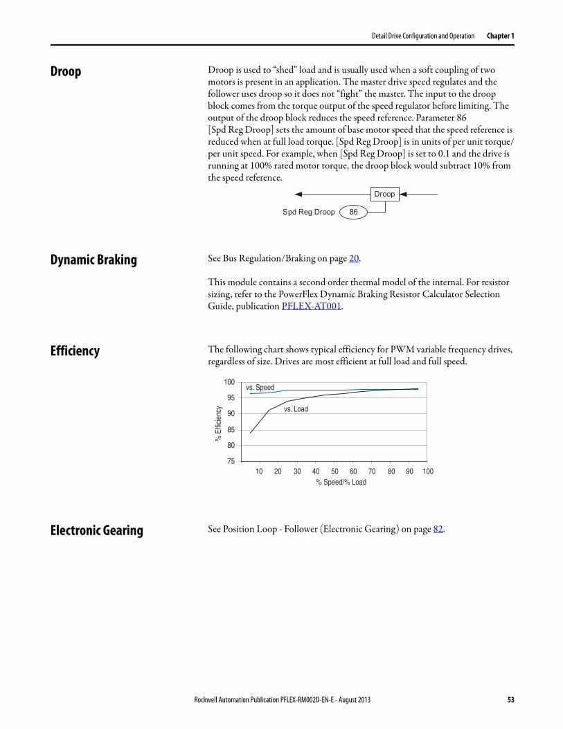
Detail Drive Configuration and Operation Chapter 1
Droop Droop is used to “shed” load and is usually used when a soft coupling of two motors is present in an application. The master drive speed regulates and the follower uses droop so it does not “fight” the master. The input to the droop block comes from the torque output of the speed regulator before limiting. The output of the droop block reduces the speed reference. Parameter 86 [Spd Reg Droop] sets the amount of base motor speed that the speed reference is reduced when at full load torque. [Spd Reg Droop] is in units of per unit torque/per unit speed. For example, when [Spd Reg Droop] is set to 0.1 and the drive is running at 100% rated motor torque, the droop block would subtract 10% from the speed reference.
Dynamic Braking See Bus Regulation/Braking on page 20.
This module contains a second order thermal model of the internal. For resistor sizing, refer to the PowerFlex Dynamic Braking Resistor Calculator Selection Guide, publication PFLEX-AT001.
Efficiency The following chart shows typical efficiency for PWM variable frequency drives, regardless of size. Drives are most efficient at full load and full speed.
Electronic Gearing See Position Loop - Follower (Electronic Gearing) on page 82.
86
Droop
Spd Reg Droop
10 20 30 40 50 60 70 80 90 100% Speed/% Load
% E
ffici
ency
vs. Speed
vs. Load
75
80
85
90
95
100
Rockwell Automation Publication PFLEX-RM002D-EN-E - August 2013 53
Chapter 1 Detail Drive Configuration and Operation
Faults Faults occur due to conditions within and/or outside the drive that could affect drive operation or application operation. These events or conditions are considered to be of significant magnitude that drive operation should or must be discontinued. Faults are brought to the user’s attention via the HIM, communication and/or contact outputs. Faults are selected during commissioning of the drive. Example of faults include: Encoder loss, communication loss or other exceptions within the drive.
Configuration:
Parameters 365 [Fdbk LsCnfg Pri] through 394 [VoltFdbkLossCnfg] and parameters 940 [+Sft OvrTrvlCnfg] through 944 [Positin Err Cnfg] program the response of the drive to various conditions. Responses include Ignore, Alarm, Fault Coast Stop, Fault Ramp Stop, and Fault Current Limit Stop.
Parameters 323 [Fault Status 1] through 325 [Fault Status 3] indicated any faults that are active.
Application Example:
Parameter 371 [Mtr OL Trip Cnfg] is set to a value of 2 “FltCoastStop”. This configures the drive to set the fault bit, parameter 323 [Fault Status 1] bit 10 “Mtr OL Trip” when the motor overload trip event occurs.
Filters The PowerFlex 700S has various filters used to assist tuning of the drive. The following section will assist the user in using the filter using frequency and time domain analysis.
Key Words
Frequency response, radians, filter, notch.
Nomenclature: Symbol Description of Symbol Units
s Laplace Operator
ω Frequency rad/sec
ωco Cut-off Frequency rad/sec
54 Rockwell Automation Publication PFLEX-RM002D-EN-E - August 2013

Detail Drive Configuration and Operation Chapter 1
Low Pass Filter
A low pass filter is designed to pass low frequencies and attenuate high frequencies. The break point between high and low is called the cut off frequency.
Figure 13 - Bode Plot Low Pass Filter (wco = 10 rad/sec)
The Process Control Loop has a low pass filter immediately after the error signal. The break frequency is set by parameter 184 [PI Lpass Filt BW]. The filter is used to eliminate unwanted noise in the feedback. Typical range is between 10 rad/sec to 50 rad/sec.
Second Order Low Pass Filter
A second order low pass filter is similar to a low pass filter, however the magnitude rolls off twice as fast as a first order low pass filter. Also the phase shift of a second order filter is from 0…180° compared to 0…90° of a first order filter.
Figure 14 - Second Order Low Pass Filter
Rockwell Automation Publication PFLEX-RM002D-EN-E - August 2013 55

Chapter 1 Detail Drive Configuration and Operation
There is a second order low pass filter in the Speed Control-Regulator. This filter is located after the speed error signal. The break frequency is set by parameter 89 [Spd Err Filt BW]. The break frequency is set to five times (5x) the Speed Loop Bandwidth. This filter is used to attenuate any high frequency noise that the speed loop would not be able to control.
Lead-Lag Filter
The PowerFlex 700S incorporates a generic lead lag filter. The filter has the following Laplace transfer function:
Kn is the gain term for the filter and Wn is the frequency term for the filter.
Lead-Lag Filter “lag”
When Kn is less than one (Kn<1) the filter behaves like a low pass filter.
Figure 15 shows the lead lag in a “lag configuration.” The unique aspect of this filter is that the gain stops once the input frequency is equal to Wn/Kn. Another aspect to this filter is that there is a mild phase shift during the attenuation.
Figure 15 - Kn < 1 “Lag Filter”
Figure 16 on page 57 shows the bode plot of the lag configuration. Kn is set to 0.7 and Wn is set to 35 rad/sec. The time domain shows a 100 rad/sec sinusoidal input. Notice that the phase shift between input and output are marginal.
Kn s wn+×s wn+
------------------------------
56 Rockwell Automation Publication PFLEX-RM002D-EN-E - August 2013

Detail Drive Configuration and Operation Chapter 1
Figure 16 - Bode Plot and Time Domain of Lag
The lag configuration is good for eliminating unwanted noise and disturbance such as backlash. There are two lead-lag blocks used in the speed regulator loop. One is in the forward path and the other is in the feedback path.
For moderate filtering:
Set Kn=0.7, Wn=0.35
For Heavy filtering:
Set Kn=0.5, Wn=20
Both the Forward and Feedback filters can be set to the same value to increase their effectiveness.
Lead-Lag Filter “Lead”
When Kn is greater than one (Kn>1), the lead-lag filter operates as lead filter. The original equation is re-written into a term that can be used to utilize the lead function. Wn is divided throughout the equation. Two new terms are developed.
Kn Wn
Forward Path Parameter 95 [SRegOut FiltGain] Parameter 96 [SReg Out Filt BW]
Feedback Path Parameter 93 [SRegFB Filt Gain] Parameter 94 [SReg FB Filt BW]
Rockwell Automation Publication PFLEX-RM002D-EN-E - August 2013 57

Chapter 1 Detail Drive Configuration and Operation
The lead term (Wld) is used to display the lead of the filter. The lag term (Wlg) is used to show the lag of the filter.
Figure 17 shows the bode plot of the lead function. The lead term is used to counteract lags in the system. The speed loop bandwidth appears to the position loop as a low pass filter or a lag. The lead filter can be used to cancel the speed loop lag and replace it with a faster lag.
Figure 17 - Kn > 1 “Lead Filter”
In the following example:• The system appears as a lag with a 5 rad/sec response.• The lead filter was set to compensate for the 5 rad/sec response (Wld=5)• The lag filter was set to 50 rad/sec response (Wlg=50)• Kn is set to Wlg/Wld (50/5) = 10• Wn is set to Wlg = 50
Kn s wn+×s wn+
------------------------------
Kn s wn 1+( )⁄×s wn 1+( )⁄
---------------------------------------------
s Wld 1+( )⁄s Wlg 1+( )⁄----------------------------------
wn Wlg=
KnWlg
Wld----------=
58 Rockwell Automation Publication PFLEX-RM002D-EN-E - August 2013
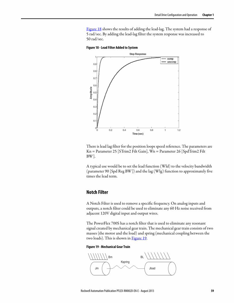
Detail Drive Configuration and Operation Chapter 1
Figure 18 shows the results of adding the lead-lag. The system had a response of 5 rad/sec. By adding the lead-lag filter the system response was increased to 50 rad/sec.
Figure 18 - Lead Filter Added to System
There is lead lag filter for the position loops speed reference. The parameters are Kn = Parameter 25 [STrim2 Filt Gain], Wn = Parameter 26 [SpdTrim2 Filt BW].
A typical use would be to set the lead function (Wld) to the velocity bandwidth (parameter 90 [Spd Reg BW]) and the lag (Wlg) function to approximately five times the lead term.
Notch Filter
A Notch Filter is used to remove a specific frequency. On analog inputs and outputs, a notch filter could be used to eliminate any 60 Hz noise received from adjacent 120V digital input and output wires.
The PowerFlex 700S has a notch filter that is used to eliminate any resonant signal created by mechanical gear train. The mechanical gear train consists of two masses (the motor and the load) and spring (mechanical coupling between the two loads). This is shown in Figure 19.
Figure 19 - Mechanical Gear Train
Kspring
BLBm
Jm Jload
Rockwell Automation Publication PFLEX-RM002D-EN-E - August 2013 59

Chapter 1 Detail Drive Configuration and Operation
The resonant frequency is defined by the following equation:
• Jm is the motor inertia (seconds).• Jload is the load inertia (seconds).• Kspring is the coupling spring constant (rad2/sec).
Figure 20 shows a two mass system with a resonant frequency of 62 rad/sec. One Hertz is equal to 2p rad/sec.
Figure 20 - Resonance
The small inset shows a better representation of resonant frequency better.
The PowerFlex 700S has a notch filter in the torque reference loop to eliminate such noise from the system. The notch filter frequency is parameter 118 [Notch Filt Freq]. Due to the fact that most mechanical frequencies are described in Hertz, [Notch Filt Freq] is in Hertz as well.
Figure 21 on page 61 shows the same mechanical gear train as in Figure 20. [Notch Filt Freq] is set to 10.
resonance KspringJm Jload+( )Jm Jload×
---------------------------------×=
60 Rockwell Automation Publication PFLEX-RM002D-EN-E - August 2013

Detail Drive Configuration and Operation Chapter 1
Figure 21 - 10 Hz Notch
Conclusion
There are several filters used in the PowerFlex 700S for various applications.
The process trim uses a simple low pass filter to eliminate undesirable noise in the feedback circuit. The cut off frequency of the low pass filter is set by parameter 184 [PI Lpass Filt BW]. Typical values would range from 15…20 rad/sec.
The speed loop uses a second order low pass filter after the speed error term is developed. The cut off frequency of the second order low pass filter is by parameter 89 [Spd Err Filt BW]. Typical value for this parameter is five times the speed loop bandwidth (parameter 90 [Spd Reg BW]).
There are several lead lag filters used in the PowerFlex 700S. The lead lag filter has two terms. The first term is the filter gain (Kn) and the second term is the filter frequency (Wn). The filter can be used as “lag” to eliminate noise from entering the control loop. The filter can be used as a “lead” to increase overall system performance.
To eliminate noise (lag) use with the light or heavy filter.
To use the lead function:• Set Wld equal to the desired lead in radians/second• Set Wlg equal to 5x Wld• Wn = Wlg• Kn = Wlg/Wld
The torque reference has a notch filter used to eliminate resonance signals. The notch frequency is set by parameter 118 [Notch Filt Freq]. This frequency is set to the mechanical resonance in hertz.
Kn Wn
Light 0.7 35
Heavy 0.5 20
Rockwell Automation Publication PFLEX-RM002D-EN-E - August 2013 61
Chapter 1 Detail Drive Configuration and Operation
Flying Start The Flying Start feature is used to start into a rotating motor, as quick as possible, and resume normal operation with a minimal impact on load or speed.
When a drive is started in its normal mode it initially applies a frequency of 0 Hz and ramps to the commanded speed. If the drive is started in this mode with the motor already spinning, large currents will be generated. An overcurrent trip may result if the current limiter cannot react quickly enough. The likelihood of an overcurrent trip is further increased if there is residual voltage on the spinning motor when the drive starts. Even if the current limiter is fast enough to prevent an overcurrent trip, it may take an unacceptable amount of time for synchronization to occur and for the motor to reach its desired frequency. In addition, larger mechanical stress is placed on the application, increasing downtime and repair costs while decreasing productivity.
The sensorless flying start function implements a frequency search algorithm that searches for the rotor speed and when found provides flux up time for the motor before transitioning to normal operation. The frequency search algorithm searches for a motor voltage that corresponds with the excitation current applied to the motor. This function is useful where very large inertia systems that would take an extended period to come to a stop if a drive trip would occur or in cases where an external source may be moving the motor before the drive would be started.
The PowerFlex 700S Phase I must be version 1.017 or later to support flying start.
Sensorless Flying Start Operation
There two modes available for the frequency search: last known frequency and preset frequency search.
Last Know Frequency
The last know frequency is the fastest method of flying start, with an initial search frequency starting at the last known operating frequency. This mode will search from the last known frequency toward zero frequency and, if the motor speed is not found, perform a start from zero speed. If the motor speed could reverse or increases to a larger speed a pull out or over voltage fault could occur. If a reversal or increase in motor speed could occur the preset frequency search should be used.
ATTENTION: The user must determine the safe frequency search configuration at the system level. Incorrect selection(s) may result in personal injury due to machine motion.
ATTENTION: The Flying Start function is only used for sensorless operation. In all other cases the motor speed is known from the feedback device and a normal start may be used even if the motor is rotating providing the user has determined that the system is safe for re-starting while rotating.
62 Rockwell Automation Publication PFLEX-RM002D-EN-E - August 2013

Detail Drive Configuration and Operation Chapter 1
Preset Frequency Search
The preset frequency search starts the frequency search at the value set in parameter 451 [SrLss Preset Spd]. From this initial search frequency the search will move towards zero. Once zero frequency is reached the algorithm will reset to the opposite direction at the same initial frequency and again search toward zero. If zero is reached a second time the drive will perform a start from zero speed. The preset frequency search routine may take the longest to execute. The value entered into parameter 451 [SrLss Preset Spd] should always be greater than the expected speed of the motor. If the motor speed is greater than the initial search frequency overvoltage trips could occur or the algorithm may not find the correct motor speed.
If the flying start function is active and the drive is started with the motor at zero speed the flying start search will add considerable extra delay to actually starting the motor.
Figure 22 - Sensorless Flying Start From Last Known Speed
Figure 23 - Sensorless Flying Start From Preset Speed
Flying Start Frequency Search
0
0.2
0.4
0.6
0.8
1
1.2
1.4
0 2 4 6 8
Time (seconds)
Freq
uenc
y
Motor Frequency
Pwm stopped
tracking rotor speed
tracking lostfrequency= 0
drive re-started
Frequency searchfrom last known speed
Rotor Speed Found
Accel to set speed and resume normal operation
motor at 50% speed
Rockwell Automation Publication PFLEX-RM002D-EN-E - August 2013 63
Chapter 1 Detail Drive Configuration and Operation
Sensorless Flying Start Configuration
Parameters 30 [Rev Speed Limit] and 31 [Fwd Speed Limit] must be set to magnitudes greater than the value set in parameter 451 [SrLss Preset Spd] to avoid over speed faults during the preset frequency search.
Parameter 222 [Motor Fdbk Sel] selects the primary speed feedback device. This parameter must be set to “2” for sensorless flying start if this is the active feedback device.
Parameter 223 [Mtr Fdbk Alt Sel] selects the alternate speed feedback device. This parameter must be set to “2” for sensorless flying start if this is the active feedback device.
Settings for parameter 222 [Motor Fdbk Sel] and 223 [Mtr Fdbk Alt Sel]:
Parameter 451 [SrLss Preset Spd] sets the initial frequency for the flying start frequency search. This value should always be set greater than the expected motor speed to avoid regeneration and the chance of an over voltage fault.
Parameter 510 [FOC Mode Config] bit 23 “SrLssFStrtEn” determines whether flying start is enabled or disabled. Setting this parameter to “1” enables the flying start function. When set to “0” the flying start function is disabled.
Parameter 510 [FOC Mode Config] bit 26 “FS PresetSpd” set to “1 uses parameter 451 [SrLss Preset Spd] as initial frequency for the flying start. When set to “0” the flying start frequency search uses the last known frequency.
Friction Compensation The friction compensation block is used to calculate breakaway torque and the torque needed just to keep the motor running at a constant speed due to friction.
Parameter 140 [FricComp Spd Ref ] is linked to parameter 43 [S Curve Spd Ref ]. The speed reference is needed because the torque needed due to friction is much more near 0 speed than at higher speeds.
Friction compensation is enabled by setting parameter 151 [Logic Command] bit 11 - “Frict Comp” to “1”.
Value Description
0 Encoder 0
1 Encoder 1
2 Sensorless
3 Reserved
4 Motor Sim
5 FB Opt Port0
6 FB Opt Port1
64 Rockwell Automation Publication PFLEX-RM002D-EN-E - August 2013

Detail Drive Configuration and Operation Chapter 1
Parameter 141 [FricComp Setup] is used to configure the friction compensation algorithm. This is a packed word of 3 digits. Each digit has a possible selection of 10 levels.
• The least significant digit sets the speed threshold in intervals of 0.0005 pu speed.
• The next (middle) digit sets the hysteresis band for the “units” digit in intervals of 0.0005 pu velocity.
• The most significant digit sets the number of time steps from stick to slip, each step is 0.002 second.
Example: Fsetup = 524 means: 5 time steps between stick and slip, each of 0.002 second. duration, 2 counts of hysteresis or 0.001 pu_speed (each count is 0.0005 pu speed), and 4 counts or 0.002 pu_speed is the trigger threshold (each count is 0.0005 pu speed).
Parameter 142 [FricComp Stick] sets the torque reference needed to break away from zero speed. Breakaway torque due to friction is always greater than running torque due to friction. This parameter is in per unit, so a value of 1 equals 100% motor torque.
Parameter 143 [FricComp Slip] sets the torque level to sustain very low speed once breakaway has been achieved. Again, the torque required to run very close to 0 speed due to friction will be greater than the torque required to run at higher speeds due to friction. This parameter is in per unit, so a value of 1 equals 100% motor torque.
Parameter 144 [FricComp Rated] sets the torque needed to keep the motor running at base motor speed and with no process loading. This parameter is in per unit, so a value of 1 equals 100% motor torque. The friction compensation algorithm assumes a linear or viscous component of friction between [FricComp Slip] and [FricComp Rated].
The friction compensation block calculates the torque needed due to friction, which shows up in parameter 145 [FricComp TorqAdd]. [FricComp TorqAdd] is summed with the output of the inertia compensation block and the torque generated by the speed reference loop. That summed torque enters the torque selection block refer to Torque Reference on page 175 for more information).
Units
Hysteresis
Number ofTime Stops
N N N
140
141
144
142
143
151 11
43
Friction Comp
FricComp Setup
FricComp Stick
FricComp Slip
FricComp Rated
145
FricComp Spd Ref
Link
to TorqueControl [4B2]
FricComp TorqAddS Curve Spd Ref
Rockwell Automation Publication PFLEX-RM002D-EN-E - August 2013 65
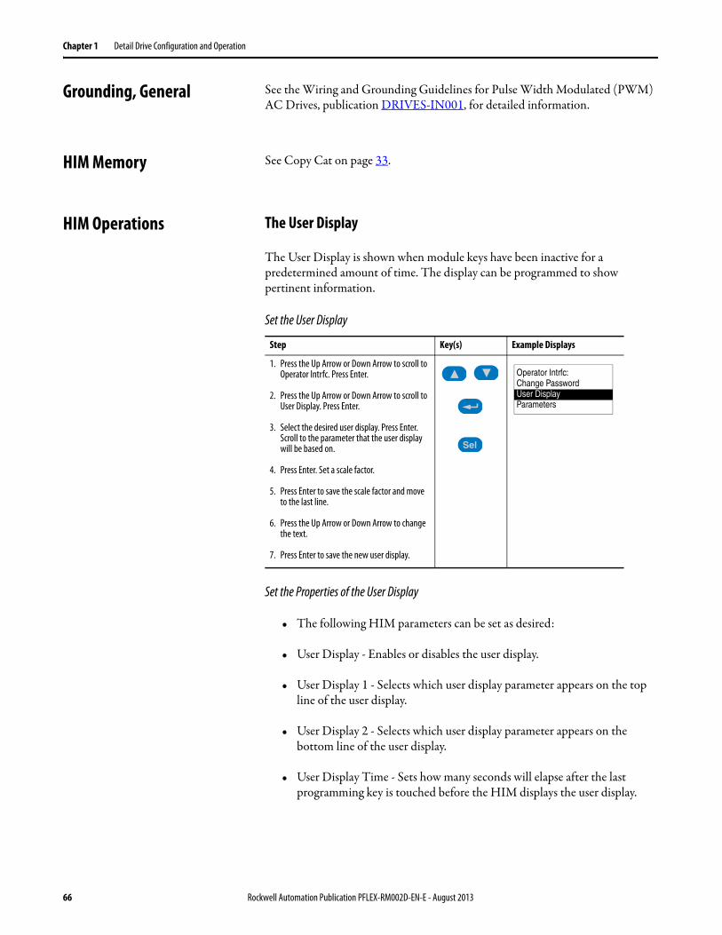
Chapter 1 Detail Drive Configuration and Operation
Grounding, General See the Wiring and Grounding Guidelines for Pulse Width Modulated (PWM) AC Drives, publication DRIVES-IN001, for detailed information.
HIM Memory See Copy Cat on page 33.
HIM Operations The User Display
The User Display is shown when module keys have been inactive for a predetermined amount of time. The display can be programmed to show pertinent information.
Set the User Display
Set the Properties of the User Display
• The following HIM parameters can be set as desired:
• User Display - Enables or disables the user display.
• User Display 1 - Selects which user display parameter appears on the top line of the user display.
• User Display 2 - Selects which user display parameter appears on the bottom line of the user display.
• User Display Time - Sets how many seconds will elapse after the last programming key is touched before the HIM displays the user display.
Step Key(s) Example Displays
1. Press the Up Arrow or Down Arrow to scroll to Operator Intrfc. Press Enter.
2. Press the Up Arrow or Down Arrow to scroll to User Display. Press Enter.
3. Select the desired user display. Press Enter. Scroll to the parameter that the user display will be based on.
4. Press Enter. Set a scale factor.
5. Press Enter to save the scale factor and move to the last line.
6. Press the Up Arrow or Down Arrow to change the text.
7. Press Enter to save the new user display.
Sel
Operator Intrfc:Change PasswordUser DisplayParameters
66 Rockwell Automation Publication PFLEX-RM002D-EN-E - August 2013

Detail Drive Configuration and Operation Chapter 1
Inertia Adaptation Inertia adaptation is used to compensate for lost motion, which occurs when a gear box and/or “springy” coupling is present. Inertia adaptation can allow the user to increase the speed regulator bandwidth by up to four times.
For example, a motor connected to a gearbox is shown:
This gearbox can be represented by a spring (k) and gear back lash (BL):
When the speed of the motor increases, there is a period of time (represented by Dx) before the teeth of the gearbox engage. After that time, there will be some twisting (like a spring) in the shaft after the teeth of the gearbox engage. This lost motion causes mechanical instability and limits how high the speed regulator bandwidth can be set without causing instability. Inertia adaptation detects the lost motion and a higher speed regulator bandwidth can be achieved without instability.
Rockwell Automation Publication PFLEX-RM002D-EN-E - August 2013 67

Chapter 1 Detail Drive Configuration and Operation
Configuration:
See Speed Regulator Tuning - Advanced Tuning for the Speed Regulator with Gearbox or Belt on page 129 for details on using inertia adaptation.
Inertia Compensation During speed changes, a certain level of torque is required due to load inertia. That level of torque is above the torque used to run at constant speed. Inertia compensation calculates that torque based on the acceleration or deceleration rate. Then that acceleration or deceleration torque can be fed forward into the torque control, making for smoother accels and decels, especially with high inertia loads.
Parameter 56 [Inertia SpeedRef ] is linked to parameter 43 [S Curve Spd Ref ]. This becomes the speed reference that the inertia compensation block uses to calculate the acceleration or deceleration rate, also known as the derivative of speed with respect to time.
Inertia compensation is enabled by turning on parameter 151 [Logic Command], bit 10 - “Inertia Comp”.
Parameter 9 [Total Inertia] is calculated during the autotune and is used along with the calculated acceleration or deceleration rate to calculate the torque adder.
Parameter 57 [InertiaAccelGain] determines the gain for the inertia compensation during acceleration. A gain of 1 results in 100% compensation. Parameter 58 [InertiaDecelGain] determines the gain for the inertia compensation during deceleration.
Parameter 60 [DeltaSpeedScale] is a multiplier for the torque output of the inertia compensation block. It is used in center wind and center unwind applications to compensate for diameter build-up.
The inertia compensation outputs the calculated torque to the parameter 59 [Inertia Torq Add]. [Inertia Torq Add] is summed with the output of the friction compensation block and the torque generated by the speed reference loop. That
Limit
303
Motor Torque Ref
InertiaAdaptation
9
300
Total Inertia
Motor Spd Fdbk
132 00
01
Inert Adapt Sel(Inrtia Adapt)
(Load Est)
133
134
Inert Adapt BW
Inert Adapt Gain
-+From Spd /Torque
Mode SelectionTo Current
Control
Torque Limits
68 Rockwell Automation Publication PFLEX-RM002D-EN-E - August 2013

Detail Drive Configuration and Operation Chapter 1
summed torque enters the torque selection block (refer to Torque Reference on page 175 for more information).
Parameter 55 [Speed Comp] contains the rate of acceleration or deceleration calculated in the inertia compensation block. This parameter is used in following applications. Link parameter 23 [Speed Trim 3] to [Speed Comp] and set parameter 24 [SpeedTrim3 Scale] to 0.002 to reduce position error in following applications.
Input Devices For information on contactors, see Motor Start/Stop Precautions on page 75.
Circuit Breakers/Fuses See the PowerFlex 700S high Performance AC Drive Phase I Control, User Manual, publication 20D-UM001.
Filters, EMC Refer to CE Conformity on page 26.
Input Modes Refer to Start/Stop Modes on page 156.
Input Power Conditioning See the Wiring and Grounding Guidelines for Pulse Width Modulated (PWM) AC Drives, publication DRIVES-IN001, for detailed information.
Jog A jog reference is usually used to run the motor at some preset, low speed. Two separate jog speeds can be used as a speed reference - parameter 17 [ Jog Speed 1] or parameter 18 [ Jog Speed 2]. A jog could be initiated by a Digital Input, by the Logic Command word from a DPI Adapter such as a HIM, or by the Logic Command word from DriveLogix. In turn, a valid jog command initiated from one of those adapters will turn on either bit 18 in parameter 152 [Applied LogicCmd] to select jog speed 1 or bit 23 in [Applied LogicCmd] to select jog
56
9
57
58
43
Inertia Comp
ΔnΔt
Inertia SpeedRef
InertiaAccelGain
InertiaDecelGain
Total Inertia
Logic Command(Inertia Comp)
59Link
S Curve Spd Ref Inertia Torq Add
to TorqueControl [4B1]
60DeltaSpeedScale
151 10
55
Speed Comp
Rockwell Automation Publication PFLEX-RM002D-EN-E - August 2013 69

Chapter 1 Detail Drive Configuration and Operation
speed 2. Note that the jog command is a maintained type of logic, so that the jog speed will be active while the jog command bit is maintained.
Links Links are software connections between two parameters. This allows one parameter to receive information from another parameter.
Each destination parameter can only have one source parameter. However, source parameters may be linked to multiple destination parameters. The information from the link always flows from the source to the destination parameter.
Several default links are set in the drive as default. Modifying these links can be done two ways:
Using the HIM
Access the destination parameter you wish to use for the link. (This cannot be done from the ALT Parameter view window, only the parameter list). When you access the parameter you want to edit, press the ALT, then the View button. This will display a window with the mode selection. Use the up/down arrow keys on the top row of buttons to select “Defined Link” and press Enter. When in this mode, pressing the Select button will allow you to enter the source parameter number.
17
Jog Speed 2
Applied LogicCmd
152 18
0
18
152 23
Jog Speed 1
0
1
1
Parameter Type Description Parameter Symbol
Source Provides information
Destination Receives information
Source
Dest.
Information
SourceSource
Dest.
Dest.
Dest.
Information
Information
70 Rockwell Automation Publication PFLEX-RM002D-EN-E - August 2013
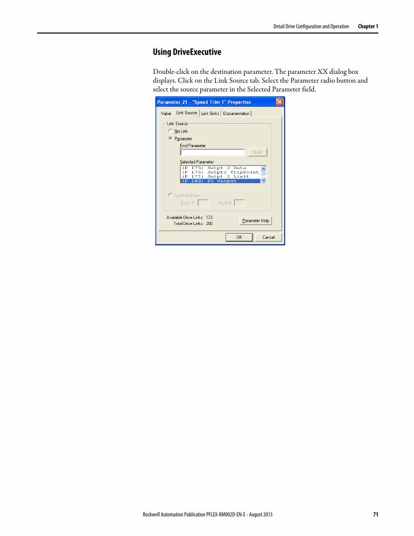
Detail Drive Configuration and Operation Chapter 1
Using DriveExecutive
Double-click on the destination parameter. The parameter XX dialog box displays. Click on the Link Source tab. Select the Parameter radio button and select the source parameter in the Selected Parameter field.
Rockwell Automation Publication PFLEX-RM002D-EN-E - August 2013 71
Chapter 1 Detail Drive Configuration and Operation
Masks A mask is a parameter that contains one bit for each of the possible adapters. Each bit acts like a valve for issued commands. Closing the valve (setting a bit value to 0) stops the command from reaching the DriveLogix. Opening the valve (setting a bit value to 1) allows the command to pass through the mask into the DriveLogix.
Table 3 - Mask Parameters and Functions
The individual bits for each parameter are as follows:• Bit 0 - “Digital Input”• Bit 1 - “Adapter 1”• Bit 2 - “Adapter 2”• Bit 3 - “Adapter 3”• Bit 4 - Not Used• Bit 5 - “Adapter 5”• Bit 6 - Not Used• Bit 7 - “DriveLogix”
Example: A customer's process is normally controlled by a remote PLC, but the drive is mounted on the machine. The customer does not want anyone to walk up to the drive and reverse the motor because it would damage the process. The local HIM (drive mounted Adapter 1) is configured with an operator's panel that includes a “REV” Button. To assure that only the PLC (connected to Adapter 5) has direction control, the [Direction Mask] can be set as follows:
This “masks out” the reverse function from all adapters except Adapter 5, making the local HIM (Adapter 1) REV button inoperable. See Owners on page 77 or the PowerFlex 700S User Manual for more information.
Motor Control Mode See Autotune on page 17.
Parameter Function
[Logic Mask] Determines which adapters can control the drive. When the bit for an adapter is set to “0,” the adapter will have no control functions except for stop.
[Start Mask] Controls which adapters can issue start commands.
[Jog Mask] Controls which adapters can issue jog commands.
[Direction Mask] Controls which adapters can issue forward/reverse direction commands.
[Fault Clr Mask] Controls which adapters can clear a fault.
Direction Mask 0 0 1 0 0 0 0 0Adapter # 7 6 5 4 3 2 1 0
72 Rockwell Automation Publication PFLEX-RM002D-EN-E - August 2013

Detail Drive Configuration and Operation Chapter 1
Motor Nameplate
Motor Overload The overload capability applies to the rated speed range.
Low Overload
After continuous operation at the rated output current, overload may be 110% rated output current (IL) for 1 minute as long as it is followed by a period of load less than the rated current so that the output current over the duty cycle does not exceed the rated output current (IL).
Example: If the duty cycle requires 110% rated output current for 1 minute of every 10 minutes, the remaining 9 minutes must be at approximately 98% rated current or less to maintain output current less than 100%. If the requirement is 1 minute out of 60 minutes, the remaining 59 minutes must be at approximately 99% rated current or less.
[Motor NP Volts]
The motor nameplate base voltage defines the output voltage, when operating at rated current, rated speed, and rated temperature.
[Motor NP FLA]
The motor nameplate defines the output amps, when operating at rated voltage, rated speed, and rated temperature. It is used in the motor thermal overload, and in the calculation of slip.
[Motor NP Hz]
The motor nameplate base frequency defines the output frequency, when operating at rated voltage, rated current, rated speed, and rated temperature.
[Motor NP RPM]
The motor nameplate RPM defines the rated speed, when operating at motor nameplate base frequency, rated current, base voltage, and rated temperature. This is used to calculate slip.
[Motor NP Power]
The motor nameplate power is used together with the other nameplate values to calculate default values for motor parameters to and facilitate the commissioning process. This may be entered in horsepower or in kilowatts as selected in the previous parameter or kW for certain catalog numbers and HP for others.
[Motor NP Pwr Units]
The rated power of the motor may be entered in horsepower or in kilowatts. This parameter determines the units on the following parameter.
[Motor Poles]
The number of motor poles - only even numbers are allowed (this may or may not appear on the nameplate).
Rockwell Automation Publication PFLEX-RM002D-EN-E - August 2013 73

Chapter 1 Detail Drive Configuration and Operation
Figure 24 - Illustration of IL
High Overload
After continuous operation at the rated output current, overload may be 150% rated output current (IH) for 1 minute as long as it is followed by a period of load less than the rated current so that the output current over the duty cycle does not exceed the rated output current (IH).
Example: If the duty cycle requires 150% rated output current for 1 minute of every 10 minutes, the remaining 9 minutes must be at approximately 92% rated current or less to maintain output current less than 100%. If the requirement is 1 minute out of 60 minutes, the remaining 59 minutes must be at approximately 98% rated current or less.
1 minute 9 minutes
1.1 x IL
Time
CurrentIL
74 Rockwell Automation Publication PFLEX-RM002D-EN-E - August 2013

Detail Drive Configuration and Operation Chapter 1
Motor Start/Stop Precautions Input Contactor
Output Contactor
Mounting As a general rule, drives should be mounted on a metallic flat surface in the vertical orientation. If considering other orientation, contact the Factory for additional data. Refer to the Chapter 1 - Installation/Wiring in the PowerFlex 700S Drive User Manual, publication 20D-UM001 for mounting instructions and limitations.
ATTENTION: A contactor or other device that routinely disconnects and reapplies the AC line to the drive to start and stop the motor can cause drive hardware damage. The drive is designed to use control input signals that will start and stop the motor. If an input device is used, operation must not exceed one cycle per minute or drive damage will occur.
ATTENTION: The drive start/stop/enable control circuitry includes solid state components. If hazards due to accidental contact with moving machinery or unintentional flow of liquid, gas or solids exist, an additional hardwired stop circuit may be required to remove the AC line to the drive. An auxiliary braking method may be required.
ATTENTION: To guard against drive damage when using output contactors, the following information must be read and understood. One or more output contactors may be installed between the drive and motor(s) for the purpose of disconnecting or isolating certain motors/loads. If a contactor is opened while the drive is operating, power will be removed from the respective motor, but the drive will continue to produce voltage at the output terminals. In addition, reconnecting a motor to an active drive (by closing the contactor) could produce excessive current that may cause the drive to fault. If any of these conditions are determined to be undesirable or unsafe, an auxiliary contact on the output contactor should be wired to a drive digital input that is programmed as ìEnable.î This will cause the drive to execute a coast-to-stop (cease output) whenever an output contactor is opened.
Rockwell Automation Publication PFLEX-RM002D-EN-E - August 2013 75

Chapter 1 Detail Drive Configuration and Operation
Output Devices Drive Output Disconnection
Rockwell Automation drives can be used with an output contactor between the drive and motor. This contactor can be opened under load without damage to the drive. It is recommended, however, that the drive have a programmed “Enable” input and that this input be opened at the same time as the output contactor.
Cable Termination
See the Wiring and Grounding Guidelines for Pulse Width Modulated (PWM) AC Drives, publication DRIVES-IN001, for detailed information.
Output Reactor
Bulletin 1321 Reactors can be used for drive input and output. These reactors are specifically constructed to accommodate IGBT inverter applications with switching frequencies up to 20 kHz. They have a UL approved dielectric strength of 4000 volts, opposed to a normal rating of 2500V. The first two and last two turns of each coil are triple insulated to guard against insulation breakdown resulting from high dv/dt. When using motor line reactors, it is recommended that the drive PWM frequency be set to its lowest value to minimize losses in the reactors.
By using an output reactor the effective motor voltage will be lower because of the voltage drop across the reactor - this may also mean a reduction of motor torque.
Output Display Output Current (Parameter 308)
Displays measured RMS drive output current. Parameter 297 [Output Curr Disp] which is the integer equivalent of parameter 308 with * internal storage in 1/10 A (10 = 1.0 A).
Output Frequency (Parameter 310)
This parameter displays the actual output frequency of the drive. The output frequency is created by a summation of commanded frequency and any active speed regulator such as slip compensation, PI Loop, bus regulator. The actual output may be different than the commanded frequency.
ATTENTION: Any disconnecting means wired to the drive output terminals U, V and W must be capable of disabling the drive if opened during drive operation. If opened during drive operation, the drive will continue to produce output voltage between U, V, W. An auxiliary contact must be used to simultaneously disable the drive.
76 Rockwell Automation Publication PFLEX-RM002D-EN-E - August 2013
Detail Drive Configuration and Operation Chapter 1
Output Power (Parameter 311)
This parameter displays the output kW of the drive. Motor Power is the calculated product of the torque reference and motor speed feedback. A 125 ms filter is applied to this result. Positive values indicate motoring power; negative values indicate regenerative power. The output power is a calculated value and tends to be inaccurate at lower speeds. It is not recommended for use as a process variable to control a process.
Output Voltage (Parameter 307)
Displays RMS line-to-line fundamental output voltage at the drive output terminals. This data is averaged and updated every 50 ms. The actual output voltage may be different than that determined by the sensorless vector or V/Hz algorithms because it may be modified by features such as the Auto-Economizer.
Overspeed Limit The absolute overspeed limit parameter, parameter 335 [Abs OverSpd Lim], is an adjustable setting. This sets a limit tolerance below parameter 30 [Rev Speed Lim] and above parameter 31 [Fwd Speed Lim], that is allowable. This can be used as a safe working speed limit.
Example 1: Speed reference is set to equal parameter 31 [Fwd Speed Lim]. Based on tuning of the drive, the speed could overshoot the commanded speed. If parameter 335 [Abs OverSpd Lim] is set equal to the forward speed limit and an overshoot is speed occurs, the drive will fault on an absolute overspeed.
Example 2: Drive is configured as a torque follower. If the mechanical connection to the load is severed, the torque command to the drive will probably be greater than the motor unloaded will require to maintain the system speed. This will cause the motor speed to increase until the torque command is met. Setting parameter 335 [Abs OverSpd Lim] to the safe motor speed will cause the fault to occur when the motor speed increase beyond this limit.
Owners An owner is a parameter that contains one bit for each of the possible adapters. The bits are set high (value of 1) when its adapter is currently issuing that command, and set low when its adapter is not issuing that command.
Table 4 - Owner Parameters and Functions
Parameter Function
[Stop Owner] Indicates the adapters that are presently issuing a valid stop command.
[Start Owner] Indicates the adapters that are presently issuing a valid start command.
[Jog Owner] Indicates the adapters that are presently issuing a valid jog command.
[Direction Owner] Indicates the adapter that currently has exclusive control of direction changes.
[Fault Clr Owner] Indicates the adapters that are presently issuing a valid start command.
Rockwell Automation Publication PFLEX-RM002D-EN-E - August 2013 77
Chapter 1 Detail Drive Configuration and Operation
The bits for each parameter are broken down as follows:• Bit 0 - “Digital Input”• Bit 1 - “Adapter 1”• Bit2 - “Adapter 2”• Bit 3 - “Adapter 3”• Bit 4 - Not Used• Bit 5 - “Adapter 5”• Bit 6 - Not Used• Bit 7 - “DriveLogix”
Ownership falls into two categories:
• Exclusive: Only one adapter at a time can issue the command and only one bit in the parameter will be high.
• Non Exclusive: Multiple adapters can simultaneously issue the same command and multiple bits may be high.
Some ownership must be exclusive; that is, only one Adapter at a time can issue certain commands and claim ownership of that function. For example, it is not allowable to have one Adapter command the drive to run in the forward direction while another Adapter is issuing a command to make the drive run in reverse. Direction Control, therefore, is exclusive ownership.
Conversely, any number of adapters can simultaneously issue Stop Commands. Therefore, Stop Ownership is not exclusive.
Example: The operator presses the Stop button on the Local HIM to stop the drive. When the operator attempts to restart the drive by pressing the HIM Start button, the drive does not restart. The operator needs to determine why the drive will not restart.
The operator first views the Start owner to be certain that the Start button on the HIM is issuing a command.
When the local Start button is pressed, the display indicates that the command is coming from the HIM.
Drive
Logix
Not U
sed
Adap
ter 5
Not U
sed
Adap
ter 3
Adap
ter 2
Adap
ter 1
Term
inal B
lock -
Digit
al In
put
Start Owner Bit 7 6 5 4 3 2 1 0Adapter # 0 0 0 0 0 0 1 0
Drive
Logix
Not U
sed
Adap
ter 5
Not U
sed
Adap
ter 3
Adap
ter 2
Adap
ter 1
Term
inal B
lock -
Digit
al In
put
Start Owner Bit 7 6 5 4 3 2 1 0Adapter # 0 0 0 0 0 0 1 0
78 Rockwell Automation Publication PFLEX-RM002D-EN-E - August 2013

Detail Drive Configuration and Operation Chapter 1
The [Start Owner] indicates that there is not any maintained Start commands causing the drive to run.
The operator then checks the Stop Owner. Notice that bit 0 is a value of “1,” indicating that the Stop device wired to the Digital Input terminal block is open, issuing a Stop command to the drive.
Until this device is closed, a permanent Start Inhibit condition exists and the drive will not restart.
Permanent Magnet Motors The following table contains a list of specifications for the permanent magnet motors compatible with PowerFlex 700S drives. Note that you must have a high resolution Stegmann or compatible resolver.
Table 5 - Motor Name Plate and Rating SpecificationsDr
iveLo
gixNo
t Use
dAd
apte
r 5No
t Use
dAd
apte
r 3Ad
apte
r 2Ad
apte
r 1Te
rmina
l Bloc
k -Di
gital
Inpu
t
Stop Owner Bit 7 6 5 4 3 2 1 0Adapter # 0 0 0 0 0 0 1 0
Model No.
Par. No. 1[Motor NP Volts]
Par. No. 2[Motor NP FLA]
Par. No. 3[Motor NP Frequency]
Par. No. 4[Motor NP RPM]
Par. No. 5[Motor NP Power]
Par. No. 7[Motor Poles]
Current peak(A rms)
System Cont. Stall Torque(N-m)
Motor Max RPM
(line to lineV rms)
(A rms) (Hz) (oper. rpm) (KW)
MPL-A310P 230 3.4 294.0 4410 0.73 8 9.9 1.58 5000
MPL-A310F 230 2.1 185.3 2780 0.46 8 6.6 1.58 3000
MPL-A320P 230 6.4 271.3 4070 1.30 8 20.9 3.05 5000
MPL-A320H 230 4.6 208.7 3130 1.00 8 13.6 3.05 3500
MPL-A330P 230 8.5 280.7 4210 1.80 8 26.9 4.08 5000
MPL-A420P 230 9.0 268.7 4030 2.00 8 32.5 4.74 5000
MPL-A430P 230 11.9 234.0 3510 2.20 8 47.4 5.99 5000
MPL-A430H 230 8.6 184.7 2770 1.80 8 31.8 6.21 3500
MPL-A4520P 230 12.4 234.0 3510 2.20 8 35.4 5.99 5000
MPL-A4520K 230 10.6 223.3 3350 2.10 8 30.4 5.99 4000
MPL-A4530F 230 9.5 144.7 2170 1.90 8 29.7 8.36 2800
MPL-A4530K 230 14.4 196.0 2940 2.50 8 43.8 8.13 4000
MPL-A4540C 230 6.6 93.3 1400 1.50 8 20.5 10.20 1500
MPL-A4540F 230 13.0 162.0 2430 2.60 8 38.2 10.20 3000
MPL-A520K 230 16.3 208.0 3120 3.50 8 46.0 10.70 4000
MPL-A540K 230 29.3 180.7 2710 5.50 8 84.9 19.40 4000
MPL-A560F 230 29.3 125.3 1880 5.50 8 84.9 27.90 3000
MPL-B310P 460 1.7 290.0 4350 0.72 8 3.0 1.58 5000
MPL-B320P 460 3.2 281.3 4220 1.30 8 5.0 2.94 5000
MPL-B330P 460 4.3 258.7 3880 1.70 8 7.0 4.18 5000
Rockwell Automation Publication PFLEX-RM002D-EN-E - August 2013 79

Chapter 1 Detail Drive Configuration and Operation
MPL-B420P 460 4.5 255.3 3830 1.90 8 9.2 4.74 5000
MPL-B430P 460 6.5 233.3 3500 2.40 8 12.0 6.55 5000
MPL-B4520P 460 6.0 260.7 3910 2.50 8 17.0 6.10 5000
MPL-B4530F 460 5.0 167.3 2510 2.20 8 13.4 8.36 3000
MPL-B4530K 460 7.8 198.0 2970 2.60 8 19.1 8.36 4000
MPL-B4540F 460 6.4 187.3 2810 3.00 8 16.3 10.20 3000
MPL-B4560F 460 8.3 144.7 2170 3.20 8 25.5 14.10 3000
MPL-B520K 460 8.1 208.0 3120 3.50 8 23.3 10.70 4000
MPL-B540K 460 14.5 177.3 2660 5.40 8 42.4 19.40 4000
MPL-B560F 460 14.5 123.3 1850 5.40 8 42.4 27.90 3000
MPL-B580F 460 18.4 132.7 1990 7.10 8 66.5 34.00 3000
MPL-B580J 460 22.6 101.3 1520 5.40 8 66.5 34.00 3800
MPL-B640F 460 22.7 106.0 1590 6.10 8 46.0 36.70 3000
MPL-B660F 460 27.2 81.3 1220 6.15 8 67.9 48.00 3000
MPL-B680D 460 24.0 123.3 1850 9.30 8 66.5 48.00 2000
MPL-B680F 460 33.9 79.3 1190 7.50 8 67.9 60.00 3000
MPL-B860D 460 33.6 96.0 1440 12.50 8 67.5 83.00 2000
MPL-B880C 460 33.6 72.7 1090 12.60 8 69.0 110.00 1500
MPL-B880D 460 40.3 86.7 1300 15.00 8 113.2 110.00 2000
MPL-B960B 460 29.7 78.7 1180 16.00 8 63.6 130.00 1200
MPL-B960C 460 38.9 76.0 1140 14.80 8 88.4 124.30 1500
MPL-B960D 460 50.2 98.0 1470 20.00 8 102.5 130.00 2000
MPL-B980B 460 31.8 72.0 1080 17.00 8 70.7 150.00 1000
MPL-B980C 460 48.2 67.3 1010 16.80 8 99.0 158.20 1500
MPL-B980D 460 63.6 93.3 1400 22.00 8 141.4 150.00 2000
MPG-A004-031 230 1.8 222.7 3340 0.21 8 4.0 0.60 6000
MPG-A010-031 230 2.1 189.3 2840 0.36 8 6.0 1.21 4875
MPG-A010-091 230 0.9 295.3 4430 0.19 8 2.3 0.41 5900
MPG-A025-031 230 9.9 181.0 1810 0.88 12 19.8 4.65 5200
MPG-A025-091 230 3.0 168.0 1680 0.52 12 8.5 2.95 5625
MPG-A050-031 230 24.7 120.0 1200 1.50 12 53.0 11.90 2510
MPG-A050-091 230 5.0 275.0 2750 0.75 12 15.6 2.60 3775
MPG-A110-031 230 20.2 122.0 1220 2.20 12 53.0 17.20 2875
MPG-A110-091 230 17.0 184.0 1840 1.60 12 33.2 8.30 3500
MPG-B010-031 460 1.6 162.7 2440 0.34 8 4.4 1.33 6450
MPG-B010-091 460 0.7 357.3 5360 0.23 8 1.5 0.41 6450
MPG-B025-031 460 4.0 219.0 2190 0.92 12 11.3 4.02 4838
MPG-B025-091 460 1.9 175.0 1750 0.54 12 5.2 2.95 5900
MPG-B050-031 460 16.3 92.0 920 1.20 12 32.5 12.40 2510
Model No.
Par. No. 1[Motor NP Volts]
Par. No. 2[Motor NP FLA]
Par. No. 3[Motor NP Frequency]
Par. No. 4[Motor NP RPM]
Par. No. 5[Motor NP Power]
Par. No. 7[Motor Poles]
Current peak(A rms)
System Cont. Stall Torque(N-m)
Motor Max RPM
(line to lineV rms)
(A rms) (Hz) (oper. rpm) (KW)
80 Rockwell Automation Publication PFLEX-RM002D-EN-E - August 2013

Detail Drive Configuration and Operation Chapter 1
MPG-B050-091 460 3.4 290.0 2900 0.79 12 9.9 2.60 4560
MPG-B110-031 460 12.9 112.0 1120 2.00 12 31.1 17.00 2420
MPG-B110-091 460 10.6 184.0 1840 1.60 12 20.5 8.30 3500
1326AB-B410G 460 2.5 118.0 3540 1.00 4 7.4 2.70 5000
1326AB-B410J 460 3.5 165.0 4950 1.40 4 10.4 2.70 7250
1326AB-B420E 460 2.8 70.0 2100 1.10 4 8.5 5.00 3000
1326AB-B420H 460 5.5 137.3 4120 2.20 4 15.6 5.10 6000
1326AB-B430E 460 3.9 67.7 2030 1.40 4 11.7 6.60 3000
1326AB-B430G 460 5.6 114.3 3430 2.30 4 16.8 6.40 5000
1326AB-B515E 460 6.1 70.3 2110 2.30 4 18.3 10.40 3000
1326AB-B515G 460 9.5 88.7 2660 2.90 4 28.5 10.40 5000
1326AB-B520E 460 6.7 71.0 2130 2.90 4 20.1 13.00 3000
1326AB-B520F 460 8.8 70.3 2110 2.90 4 26.4 13.10 3500
1326AB-B530E 460 9.5 74.3 2230 4.20 4 28.5 18.00 3000
1326AB-B720E 460 17.5 70.0 2100 6.80 4 52.5 30.90 3500
1326AB-B720F 460 27.5 117.0 3510 11.70 4 66.5 31.80 5000
1326AB-B730E 460 22.8 78.3 2350 9.60 4 66.5 39.00 3350
1326AB-B740C 460 20.9 52.3 1570 8.70 4 62.7 53.00 2200
1326AB-B740E 460 32.0 79.7 2390 12.70 4 66.5 50.80 3400
0.0
1326AS-B310H 460 0.8 204.5 4090 0.30 6 2.4 0.70 6200
1326AS-B330H 460 2.1 204.5 4090 0.90 6 6.0 2.10 6500
1326AS-B420G 460 2.6 179.0 3580 1.20 6 7.8 3.20 5250
1326AS-B440G 460 5.4 149.0 2980 2.00 6 16.2 6.40 5250
1326AS-B460F 460 6.2 148.5 2970 2.80 6 18.6 9.00 4300
1326AS-B630F 460 7.8 142.7 2140 2.40 8 18.5 10.70 4500
1326AS-B660E 460 11.8 100.7 1510 3.40 8 29.8 21.50 3000
1326AS-B690E 460 19.0 87.3 1310 5.00 8 41.3 36.40 3000
1326AS-B840E 460 21.2 79.3 1190 4.70 8 39.5 37.60 3000
1326AS-B860C 460 17.6 77.3 1160 6.00 8 44.4 49.30 2000
1326AH-B330F 460 2.1 0.0 3000 0.75 9.0 3000
1326AH-B440F 460 3.3 0.0 2500 1.22 13.8 2500
1326AH-B540F 460 11.1 0.0 2500 2.60 47.2 2500
3050R-7 390 66.0 50.0 500 30.00 12 132.0 500
11050R-7 390 218.0 50.0 500 110.00 12 436.0 500
Model No.
Par. No. 1[Motor NP Volts]
Par. No. 2[Motor NP FLA]
Par. No. 3[Motor NP Frequency]
Par. No. 4[Motor NP RPM]
Par. No. 5[Motor NP Power]
Par. No. 7[Motor Poles]
Current peak(A rms)
System Cont. Stall Torque(N-m)
Motor Max RPM
(line to lineV rms)
(A rms) (Hz) (oper. rpm) (KW)
Rockwell Automation Publication PFLEX-RM002D-EN-E - August 2013 81
Chapter 1 Detail Drive Configuration and Operation
Position Loop - Follower (Electronic Gearing)
Technical Information
General facts about using the Position Loop for follower applications:
• Parameter 768 [PositReg P Gain] is used for tuning.
• Parameter 770 [Posit Reg Integ] is normally not needed for position following applications and is disabled by factory default.
• The number of position counts per revolution depends on the type of feedback device used:
• When using an encoder for positioning, the drive uses quadrature counts. 1024 encoder = 4096 counts per motor revolution.
• When using a Stegmann absolute hi-resolution encoder, the drive counts 1048576 counts per revolution.
• When using a Resolver, the drive counts 65536 counts per revolution.
• Speed regulator tuning directly affects the position loop performance. The speed regulator should be tuned before the position loop.
• For best performance, positioning should be used with a dynamic brake or regenerative system.
Overview
The position follower feature gives the user the ability to follow the position of a master motor without an external position controller. The position loop adds to or subtracts from the speed reference (using parameter 22 [Speed Trim 2]) to correct for the following error and keep the positions of both encoders locked. The resulting motor speed reference enters the speed regulator loop. Gear ratios can be set up to follow at different rates of speed and position. Typical applications for a geared follower would be for a roller following another part of a machine, and a filler and capper machine for bottling.
82 Rockwell Automation Publication PFLEX-RM002D-EN-E - August 2013

Detail Drive Configuration and Operation Chapter 1
The following is a block diagram overview of the position follower mode:
Speed Reference Selection
For the position following mode to work properly, there needs to be a speed reference to the speed loop of the drive to follow.
For example, link parameter 12 [Speed Ref 2] to parameter 241 [Encdr1 Spd Fdbk]. Set parameter 16 [Speed Ref Sel] = 1 “Speed Ref 1". This generates the speed command from the master encoder input. If a gear ratio is used in the position loop, parameter 13 [Spd Ref2 Multi] must be setup to match the gear ratio set in the position loop.
Speed Reference Ramp
The speed reference ramp should be disabled when using the drive as a position follower. To disable the speed reference ramp, set parameter 151 [Logic Command] bit 0 “SpdRamp Dsbl” = 1.
Speed RefSelection
Linear Ramp& S Curve
16Speed Ref Sel
40 43
Speed Control - Reference (2ms)Selected Spd Ref S Curve Spd Ref
10
11
12
13
/
*
PIRegulator
81
82
Spd Reg P Gain
Spd Reg I Gain
300
Motor Spd Fdbk
302Spd Reg PI Out
Speed Control - Regulator (0.5ms)
Motor Speed Ref
90Spd Reg BW
301+22
743Aux Posit Ref
Gear Rat
[ N ][ D ]
+Position Offset
PI Regulator
762Mtr Posit FB
318Posit Spd Output
Position Control (2ms)
Speed Trim 2
Speed Ref 1
Speed Ref 2
Spd Ref1 Divide
Spd Ref2 Multi
fromMaster Encdr
fromMaster Encdr
fromFollower Encdr
fromFollower Encdr
Speed RefSelection
16Speed Ref Sel
40Selected Spd Ref
10
11
12
13
/
*
Speed Ref 1
Speed Ref 2
Spd Ref1 Divide
Spd Ref2 Multi
fromMaster Encdr
Rockwell Automation Publication PFLEX-RM002D-EN-E - August 2013 83

Chapter 1 Detail Drive Configuration and Operation
Enabling the Position Loop
To enable the position loop, set parameter 151 [Logic Command] bit 13 “PositionEnbl” = 1.
Then to allow the output of the position loop to trim the speed set parameter 740 [Position Control] bit 1 “Speed Out En” = 1.
Position Reference Selection
For a position follower application set parameter 742 [Posit Ref Sel] = 1 “Aux PositRef ”. This uses counts from a linked source for the position reference to the position loop.
Link parameter 742 [Aux Posit Ref ] to the position for the feedback device. For example, link parameter 742 [Aux Posit Ref ] to parameter 240 [Encdr1 Position]. Encoder 1 position becomes the position reference for the position loop.
Set the EGR (Electronic Gear Ratio) and Speed Reference Scaling
Position reference can be entered in user units by using the EGR scaling. Parameters 745 [PositRef EGR Mul] and 746 [PositRef EGR Div] are used to scale the position reference.
Example: In this example the encoders are mounted on the motors. The motors are directly coupled to the load and we want the follower to run at 4 times the speed of the master.PPRm = 1024 PPRPPRf = 1024 PPRRatiof:Ratiom = 4:1
0
1
2
749
743
742
Interp Position
Posit Ref Sel
758
Aux PositRef
Pt-Pt Posit Ref
SelectedPositionReference
Gear Rat
[ N ][ D ]
745
746
PositRef EGR Mul
PositRef EGR Div
Accum
744 PositRef EGR Out
Deriv
Δ
∑Selected position
referenceGeared position
reference
84 Rockwell Automation Publication PFLEX-RM002D-EN-E - August 2013

Detail Drive Configuration and Operation Chapter 1
where:
where:
Solving for the lowest common denominator, the 1024s on the top and bottom cancel out so that:
Therefore, parameter 745 [PositRef EGR Mul] = 4 and parameter 746 [PositRef EGR Div] = 1. This will set up the position loop of the follower to move 4 counts for every 1 count of the master.
[Spd Ref 2 Multi] is calculated:
Notice that the encoder PPRs should not be included in the calculation for parameter 13 [Spd Ref2 Multi].
[Spd Ref2 Multi] is rounded to the 4th decimal place. The position loop gear ratios will be exact, so that the follower tracks at 4 times the master's speed.
Position Offset
Offsets can be added to the position reference. Offsets are used to make a correction move to synchronize the follower to the master position.
PPRm = the PPR of the master encoderPPRf = the PPR of the follower encoderRatiof:Ratiom = the desired ratio between the follower speed and the master speed
CPRf = the counts per revolution of the follower feedback device. For an incremental encoder this is 4 times the encoder PPR. For a Stegmann Hi-Res encoder this is 1048576. For a Resolver this is 65536.
CPRm = the counts per revolution of the master encoder. For an incremental encoder this is 4 times the encoder PPR. For a Stegmann Hi-Res encoder this is 1048576. For a Resolver this is 65536.
1409644096
Div] EGR [PositRefMul] EGR [PositRef ==
RatiomCPRmRatiofCPRf
14
Div] EGR [PositRefMul] EGR [PositRef =
414]Multi Ref2 Spd[ ===
RatiomRatiof
+Rate Lim
753
754
755 LPassFilter
756Posit Offset 1
Posit Offset 2
Posit Offset Spd
Position Control(X Offset Pol)
Position Control(X Offset Ref)
Deriv
Δ
740 04
740 05
741 05 Position Status(X OffRefActl)
Added to positionreference afterEGR
Rockwell Automation Publication PFLEX-RM002D-EN-E - August 2013 85

Chapter 1 Detail Drive Configuration and Operation
There are two offsets, parameters 753 [Posit Offset 1] and 754 [Posit Offset 2]. The offset speed must be entered in parameter 755 [Posit Offset Speed] - if this is left at zero the move will not occur. The position offset must be entered in counts of feedback because it is added to the position reference after the EGR scaling. Offsets must be maintained to keep the position (i.e., if you enter a 300 in the offset the position loop will move 300 counts extra). If you zero the offset command the motor will return to the previous position. When it is necessary to zero the offset after a move without returning to the previous position, set parameter 740 [Position Control] bit 5 “Xoff ReRef ” = 1. Then set the offset value = 0. Then set [Position Control] bit 5 “Xoff ReRef ” = 0. The system will not make an offset move when [Position Control] bit 5 “Xoff ReRef ” is on.
Position Loop Output Limits
Parameter 775 [Xreg Spd LoLim] sets the negative speed limit at which the position regulator will output. The default is set to -10% of the base motor speed.
Parameter 776 [Xreg Spd HiLim] sets the positive speed limit at which the position regulator will output. The default is set to +10% of the base motor speed.
In position follower, the position loop only needs to trim the speed a small amount because the drive is setup to follow the master speed reference. Therefore, [Xreg Spd LoLim] and [Xreg Spd HiLim] can be left at the defaults.
Tuning Tips
The speed regulator of the drive must be tuned prior to tuning the Position Loop. See Speed PI Regulator on page 120 for tips on tuning the speed regulator.
Typically parameter 768 [PositReg P Gain] should be set between 1/5th to 1/3rd of parameter 90 [Spd Reg BW].
Parameter 768 [PositReg P Gain] may be set higher using lead compensation on the Position Regulator Output. Lead/Lag filtering of the position regulator output is accomplished via the speed trim 2 filter. Set parameters 25 [Strim2 Filt Gain] and 26 [SpdTrim2 Filt BW] so that:
For example, with parameter 90 [Spd Reg BW] = 40 rad/sec, set parameter 26 [SpdTrim2 Filt BW] = 200 rad/sec and set parameter 25 [Strim2 Filt Gain] = 5. The lead/lag filter will effectively cancel the 1/40 second lag. This will allow a higher [PositReg P Gain] for increased stability.
BW] Reg [SpeedGain]Filt [Strim2
BW]Filt [SpdTrim2 =
86 Rockwell Automation Publication PFLEX-RM002D-EN-E - August 2013

Detail Drive Configuration and Operation Chapter 1
Parameter 770 [PositReg Integ] is the integral gain for the position loop. [PositReg Integ] can be used but is disabled by default and is normally not needed for position follower applications. To enable [PositReg Integ], set parameter 740 [Position Control], bit 2 “Integ En” = 1. When [PositReg Integ] is used, parameters 772 [XReg Integ LoLim] and 773 [XReg Integ HiLim] should be set with narrow limits.
Jogging a Position Follower Independent from the Master
Version 1.xxx - When you want to jog the PowerFlex 700S follower drive independently, turn off parameter 740 [Position Control] bit 1 “Posit Spd Output” to disable the position loop output.
Version 2.xxx - The jog can be performed while the position loop output is enabled.
Position Loop - In Position Detect
The In Position Detection determines if parameter 769 [Position Error] is within a user defined value. Parameter 769 [Position Error] is the result of parameter 747 [Position Cmmd] - parameter 762 [Mtr Posit Fdbk].
Parameter 782 [In Posit BW] sets the absolute number of position counts that parameter 769 [Position Error] must be within for parameter 741 [Position Status] bit 10 “In Position” to turn on.
Parameter 783 [In Posit Dwell] sets a delay time in seconds that parameter 769 [Position Error] must be within parameter 782 [In Posit BW] before parameter 741 [Position Status] bit 10 “In Position” turns on.
Position Loop - Point to Point Technical Information
First a few general facts about the Point to Point Position Loop:
• Uses only parameter 768 [PositReg P Gain] for tuning. Parameter 770 [Posit Reg Integ] is not used in point to point mode.
• The number of position counts per revolution depends on the type of feedback device used:
In Position Detect
769
782
783
741 10
In Posit BW
In Posit Dwell
Position Error Position Status(In Position)
Rockwell Automation Publication PFLEX-RM002D-EN-E - August 2013 87
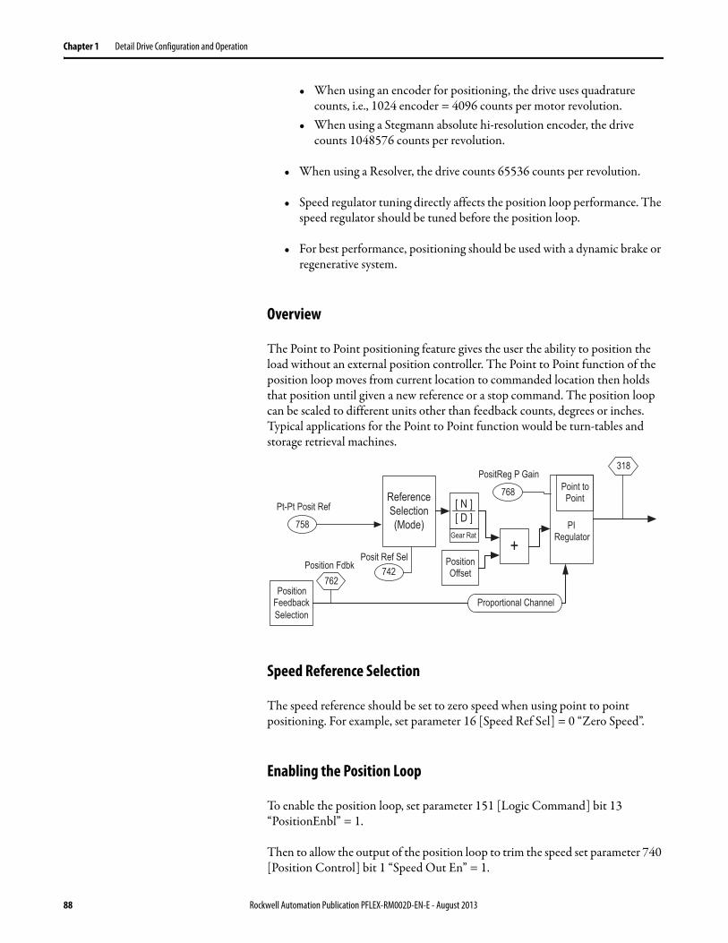
Chapter 1 Detail Drive Configuration and Operation
• When using an encoder for positioning, the drive uses quadrature counts, i.e., 1024 encoder = 4096 counts per motor revolution.
• When using a Stegmann absolute hi-resolution encoder, the drive counts 1048576 counts per revolution.
• When using a Resolver, the drive counts 65536 counts per revolution.
• Speed regulator tuning directly affects the position loop performance. The speed regulator should be tuned before the position loop.
• For best performance, positioning should be used with a dynamic brake or regenerative system.
Overview
The Point to Point positioning feature gives the user the ability to position the load without an external position controller. The Point to Point function of the position loop moves from current location to commanded location then holds that position until given a new reference or a stop command. The position loop can be scaled to different units other than feedback counts, degrees or inches. Typical applications for the Point to Point function would be turn-tables and storage retrieval machines.
Speed Reference Selection
The speed reference should be set to zero speed when using point to point positioning. For example, set parameter 16 [Speed Ref Sel] = 0 “Zero Speed”.
Enabling the Position Loop
To enable the position loop, set parameter 151 [Logic Command] bit 13 “PositionEnbl” = 1.
Then to allow the output of the position loop to trim the speed set parameter 740 [Position Control] bit 1 “Speed Out En” = 1.
ReferenceSelection(Mode)758
Pt-Pt Posit Ref
742Posit Ref Sel
Gear Rat
[ N ][ D ]
+PositionOffset
PIRegulator
Point toPoint768
PositReg P Gain
762Position Fdbk
318
PositionFeedbackSelection
Proportional Channel
88 Rockwell Automation Publication PFLEX-RM002D-EN-E - August 2013

Detail Drive Configuration and Operation Chapter 1
Position Reference Selection
For point to point positioning set parameter 742 [Posit Ref Sel] = 2 “Pt to Pt”. Parameter 758 [Pt-Pt Posit Ref ] becomes the reference for the position.
Position Reference Scaling
Position reference can be entered in user units by using the EGR scaling. Parameters 745 [PositRef EGR Mul] and 746 [PositRef EGR Div] are used to scale the position reference.
Example: To use degrees of motor revolution for the positioning units, scale as follows:
With a 1024 encoder on the motor, this translates to 4096 counts per revolution quadrature position counts.
This scaling translates the position reference of 0…360 degrees to 0…4096 position counts. This will allow you to enter degrees of motor rotation for the position reference.
0
1
2
749
743
742
Interp Position
Posit Ref Sel
758
Aux PositRef
Pt-Pt Posit Ref
SelectedPositionReference
Gear Rat
[ N ][ D ]
745
746
PositRef EGR Mul
PositRef EGR Div
Accum
∑ 744 PositRef EGR Out
Deriv
ΔSelected positionreference
Geared positionreference
Parameter 745 [PositRef EGR Mul] = 4096Parameter 746 [PositRef EGR Div] = 360
Rockwell Automation Publication PFLEX-RM002D-EN-E - August 2013 89

Chapter 1 Detail Drive Configuration and Operation
Position Offset
Offsets can be added to the position reference. Offset are used to make a correction move to sync the follower to the master position.
There are two offsets, parameters 753 [Posit Offset 1] and 754 [Posit Offset 2]. The offset speed must be entered in parameter 755 [Posit Offset Speed] - if this is left at zero the move will not occur. The position offset must be entered in counts of feedback because it is added to the position reference after the EGR scaling. Offsets must be maintained to keep the position. In other words, if you enter a 300 in the offset the position loop will move 300 counts extra. If you zero the offset command the motor will return to the previous position. When it is necessary to zero the offset after a move without returning to the previous position, set parameter 740 [Position Control] bit 5 “Xoff ReRef ” =1. Then set the offset value = 0. Then set [Position Control] bit 5 “Xoff ReRef ” = 0. The system will not make an offset move when [Position Control] bit 5 “Xoff ReRef ” is on.
+Rate Lim
753
754
755 LPassFilter
756Posit Offset 1
Posit Offset 2
Posit Offset Spd
Position Control(X Offset Pol)
Position Control(X Offset Ref)
Deriv
Δ
740 04
740 05
741 05 Position Status(X OffRefActl)
Added to positionreference afterEGR
90 Rockwell Automation Publication PFLEX-RM002D-EN-E - August 2013
Detail Drive Configuration and Operation Chapter 1
Point to Point Acceleration and Deceleration
Parameter 759 [Pt-Pt Accel Time] sets the acceleration time in seconds from zero to base motor speed.
Parameter 760 [Pt-Pt Decel Time] sets the deceleration time in seconds from base motor speed to zero.
The [Pt-Pt Accel Time] and [Pt-Pt Decel Time] are only active in Point to Point mode. The Default = 10 seconds.
Position Loop Output Limits
Parameter 772 [Xreg Spd LoLim] sets the negative speed limit at which the position regulator will output. The default is set to -10% of the base motor speed. Set this to the negative speed at which you want the drive to run for point to point moves.
Parameter 773 [Xreg Spd HiLim] sets the positive speed limit at which the position regulator will output. The default is set to +10% of the base motor speed. Set this to the positive speed at which you want the drive to run for point to point moves.
Tuning Tips
The speed regulator of the drive must be tuned prior to tuning the Position Loop. See Speed PI Regulator on page 120 for tips on tuning the speed regulator.
Do not attempt to set the accel/decel rates of the point to point position loop faster than can be accomplished by the system. Attempting to set the accel/decel rates faster than the system can handle will cause instability in the position loop. Do not attempt to operate beyond the torque limits of the drive motor combination.
Typically parameter 768 [PositReg P Gain] should be set between 1/5th to 1/3rd of parameter 90 [Spd Reg BW].
Parameter 768 [PositReg P Gain] may be set higher using lead compensation on the Position Regulator Output. Lead/Lag filtering of the position regulator output is accomplished via the speed trim 2 filter. Set parameters 25 [Strim2 Filt Gain] and 26 [SpdTrim2 Filt BW] so that:
BW] Reg [SpeedGain]Filt [Strim2
BW]Filt [SpdTrim2
Rockwell Automation Publication PFLEX-RM002D-EN-E - August 2013 91

Chapter 1 Detail Drive Configuration and Operation
For example, with parameter 90 [Spd Reg BW] = 40 rad/sec, set parameter 26 [SpdTrim2 Filt BW] = 200 rad/sec and set parameter 25 [Strim2 Filt Gain] = 5. The lead/lag filter will effectively cancel the 1/40 second lag. This will allow a higher [PositReg P Gain] for increased stability.
Parameter 761 [Pt-Pt Filt BW] sets the bandwidth of a low pass filter which affects smoothness at the start of deceleration in point to point mode. A high filter bandwidth will produce a more square deceleration torque, one with a higher level of jerk. Typical values are 5…100 (rad/sec). A zero value will bypass the filter. Too high of a value in [Pt-Pt Filt BW] will cause unstable operation at the end of the move. The Default = 25 rad/sec.
Jogging
When you want to jog the PowerFlex 700S, turn off parameter 740 [Position Control] bit 1 - “Speed Out En” to disable the position loop output.
Point to Point Re-Reference
Parameter 740 [Position Control] bit 10 “Pt-Pt ReRef ” allows the user to perform a position redefine when active. When this bit is set, the position reference in parameter 758 [Pt-Pt Posit Ref ] can be changed to the position value desired for the current location. This can be used as a home zero setup by moving the load to the home position.
Example: Set parameter 740 [Position Control] bit 10 - “Pt-Pt ReRef ” = 1. Then set parameter 758 [Pt-Pt Posit Ref ] =0. Also if [Pt-Pt Posit Ref ] is set to a different number, that will become the new position value. After setting [Pt-Pt Posit Ref ] to the desired value, set [Position Control] bit 10 “Pt-Pt ReRef ” = 0.
Position Loop - Position Watch
The position watch is used to determine when the position feedback reaches a user defined value. There are two position watches in the PowerFlex 700S.
Parameter 784 [Posit Detct1 In] sets the position feedback that you would like to watch. By default, [Posit Detct1 In] is linked to parameter 763 [Position Actual].
Note: In order for the value in parameter 763 [Position Actual] to change the firmware function for the position loop must be turned on by setting parameter 147 [FW Functions En] bit 16 “Position Ctrl” = 1 and the position loop must be enabled by setting parameter 151 [Logic Command] bit 13 “Position En” = 1.
Position Watch 1
763
780
741 08
Position Actual
Position Control(X Watch 1 En)(X Watch 1 Dir)
PositDetct1 Stpt
Position Status(Posit Watch1)784
Posit Detct1 In
Link
740 16
740 17
92 Rockwell Automation Publication PFLEX-RM002D-EN-E - August 2013

Detail Drive Configuration and Operation Chapter 1
Parameter 780 [PositDetct1 Stpt] is used to set the position set point for which to watch.
Setting parameter 740 [Position Control] bit 17 “X Watch 1 Dir” = 1 causes the drive to detect when the position feedback becomes greater than the set point. Setting [Position Control] bit 17 “X Watch 1 Dir” = 0 causes the drive to detect when the position feedback becomes less than the set point.
Setting parameter 740 [Position Control] bit 16 “X Watch 1 En” = 1 enables the position detection function to detect the next position. Setting [Position Control] bit 16 “X Watch 1 En” = 0 resets position detection.
Setting parameter 741 [Position Status] bit 8 “Posit Watch1” = 1 indicates that the position set point has been passed.
Example:• Set parameter 147 [FW Functions En] bit 22 “PosWtch/Dtct” = 1.• Link parameter 784 [Posit Detct1 In] to parameter 240 [Encdr1 Position].• Set parameter 780 [PositDetct1 Stpt] = 100000 counts.• Set parameter 740 [Position Control] bit 17 “X Watch 1 Dir” = 1.• Set parameter 740 [Position Control] bit 16 “X Watch 1 En” = 1.
When parameter 240 [Encdr1 Position] becomes greater than 100000 counts, parameter 741 [Position Status] bit 8 “Posit Watch1” is set to 1. Note that the position must pass 100000 counts. If the motor position is already past 100000 counts when the position watch is enabled, the position watch status bit will not detect the position until 100000 counts is passed again.
Set parameter 740 [Position Control] bit 16 “X Watch 1 En” = 0 to reset parameter 741 [Position Status] bit 8 “Posit Watch1” to 0.
Rockwell Automation Publication PFLEX-RM002D-EN-E - August 2013 93

Chapter 1 Detail Drive Configuration and Operation
Position Loop - Registration The PowerFlex 700S drive has the ability to capture the feedback position upon an event occurrence. There are two registration registers that can be configured. You may also see DriveLogix Motion instruction Motion Arm Registration (MAR).
Port 0 Example
Sequence of events:
Registration for Port 0 is configured using the parameters below. After configuration the Registration latch is armed. After the registration event occurs, the Found bit will be turned on. This indicates that the position of the event has been trapped in the Registration Latch parameter.
P235 [Port0 Regis Ltch] Displays the captured position after the event occurs.
P236 [Port0 Regis Cnfg] Configures the Registration event.
Encoder Selection
Bit 0 Description
0 Select Encoder0 to trap position
1 Select Encoder1 to trap position
Trigger Source
Bit 2 Bit 1 Description
0 0 Digital Input 1 and Encoder 0 Z phase
0 1 Digital Input 3 ( Default setting)
1 0 Digital Input 2
1 1 Encoder 0 Z phase
Edge Selection Settings
Bit 4 Bit 3 Description
0 0 Capture on Rising Edge
0 1 Capture on Falling Edge
1 0 Capture on Both Edges
1 1 Disable Capture
Trigger Source
Bit 6 Bit 5 Description
0 0 Disable Capture
0 1 Capture during Reverse Rotation
1 0 Capture during Forward Rotation
1 1 Capture during either Rotation
94 Rockwell Automation Publication PFLEX-RM002D-EN-E - August 2013

Detail Drive Configuration and Operation Chapter 1
Table 6 - Filter Settings
P237 [Port0 Regis Ctrl] Configures control for Port 0 Registration:Setting Bit 0 = 1 is the arm request to capture the position on the next trigger event. Setting Bit 1 = 1 is the disarm request to capture on the next trigger event.
P238 [Port0 Regis Stat] Port 0 Registration Status:Bit 0 [Armed] indicates the registration latch is armed and waiting for a trigger.Bit 1 [Found] indicates the registration event has occurred and the value is stored in P235 [Port0 Regis Ltch].
Power Loss/Ride Through The precharge function provides a current limited charging of the drive's bus capacitor(s) and, when charging is complete, bypasses the current limiting device. This current limited charging primarily protects the drive's input fuses and front-end rectifiers (or SCRs) from excessive inrush current. The bypass function is needed for normal drive operation to avoid overloading the current limiting device. In general, when precharge is active, the current limiting device is in circuit and when precharge is done the bypass device is active (see exceptions below).
The ride through function can provide a motor coast, precharge and auto-restart sequence of operation in the event of an input power dropout (power loss and return). First the drive stops PWM operation “coasting the motor” and saving any remaining power stored in the drive's bus capacitor(s) for extended control logic operating time. Next, the precharge function limits the drive's inrush current in the event that the incoming power to the drive is restored. Last, after the power is
Bit Input Filter Setting
11 10 9 8
0 0 0 0 Filter disabled
0 0 0 1 100 ns filter
0 0 1 0 200 ns filter
0 0 1 1 300 ns filter
0 0 1 1 300 ns filter
0 1 0 0 400 ns filter
0 1 0 1 500 ns filter
0 1 1 0 600 ns filter
0 1 1 1 700 ns filter
1 0 0 0 800 ns filter (default setting)
1 0 0 1 900 ns filter
1 0 1 0 1000 ns filter
1 0 1 1 1100 ns filter
1 1 0 0 1200 ns filter
1 1 0 1 1300 ns filter
1 1 1 0 1400 ns filter
1 1 1 1 1500 ns filter
Rockwell Automation Publication PFLEX-RM002D-EN-E - August 2013 95

Chapter 1 Detail Drive Configuration and Operation
restored and the precharge has completed, ride through allows the drive to continue normal operation, applying power to the motor again. This operation is intended to protect the drive from excessive inrush currents in the presence of input AC line disturbances and allows the drive to continue normal operation without user intervention. However, there is also a concern for safe auto-restart operation. By default the drive is configured to fault and not auto-restart if the power line dropout lasts more than two seconds.
Precharge Frames 1…4
The precharge implementation and control varies with drive size and type. For frames 1…4 the precharge hardware is located on the power circuit board. This is basically a resistor and bypass relay in series with the positive DC bus between the front-end rectifier and the bus capacitor. The bypass relay control is described below. Also note that these drives can be wired for either AC line power or DC common bus. The precharge function will work the same for either AC or DC power input.
Precharge Frames 5 and Higher AC Input “Stand Alone Drives”
For frames 5 and higher (AC Input) the precharge function is implemented with an SCR rectifier such that the SCRs are phase advanced to limit the inrush current into the bus capacitor(s). This phase advanced precharge is not controlled by the drive and should normally be completed by the minimum precharge time required by the drive. The drive will not complete precharge until the bus voltage is stable and above the under voltage level.
Precharge Frames 5 and Higher DC Input “Common Bus Drives”
There are two versions of these DC Input or common bus drives. The first has a resistor with an SCR bypass in series with the positive DC bus in front of the bus capacitor. The second does not have any precharge hardware and is intended for user applications where the precharge hardware and control is provided by the user. Drives with the resistor and SCR bypass (internal) have the same precharge control as frame 1…4 above.
ATTENTION: The user must determine safe auto-restart and fault configuration at the system and user level. Incorrect selection(s) may result in personal injury due to machine motion.
ATTENTION: In cases where the user is providing the precharge hardware and control incorrect configuration and/or control may result in drive damage.
96 Rockwell Automation Publication PFLEX-RM002D-EN-E - August 2013

Detail Drive Configuration and Operation Chapter 1
Ride Through Operation
An incoming power loss to the drive is detected by a 22% drop in bus voltage or a bus voltage that drops below the under voltage level. The return of incoming power is detected by an 11% rise in bus voltage and a bus voltage level greater than the undervoltage level set in parameter 409 [Line Undervolts]. If the undervoltage condition is selected as a fault, parameter 393 [BusUndervoltCnfg], then the drive will not restart if the incoming power returns. Upon sensing a power loss the drive can be configured to coast, continue operation or change to flux only operation. (See Ride Through Configuration below).
In cases where the precharge control is independent or external to the drive (firmware) the ride through function can still be used to stop PWM operation saving controller power and restart operation after the return of power is sensed. In this case ride through sequence will not be directly coordinated with the precharge operation. For external precharge hardware functionality is provided so that the user may provide coordinated operation.
Ride Through Configuration
The drive's response to a power disturbance can be selected in parameter 406 [Power Loss Mode].
Settings for Parameter 406 [Power Loss Mode]:
Coast (default): The coast mode stops power to the motor (PWM disabled) and the motor coasts until power returns or a fault occurs. At the time when the motor PWM is disabled the precharge device bypass (where controlled by the drive) is also opened. Then the precharge logic is reset so that the drive starts another precharge cycle. After the incoming power returns and the precharge cycle has completed, the drive restarts normal operation.
Continue: Disables the ride through function and will attempt to continue running if the incoming power is disrupted. If the power returns before the drive has shut down, the precharge device will be bypassed and a large inrush current may occur. In this case, drive damage is likely if the inrush current is large.
408 Power Loss LevelSets the bus voltage level at which ride-through begins and modulation ends. When bus voltage falls below this level, the drive prepares for an automatic reset. Enter a percentage of the bus voltage derived from the high voltage setting for the voltage classFor example: on a 400-480V drive,
Units:Default:Min/Max:
%22.115/95
x 16-bit Integer
0.221 480Vac 2×× 150Vdc=
0 Coast1 Reserved2 Continue3 Reserved4 Reserved5 Flux Only
Rockwell Automation Publication PFLEX-RM002D-EN-E - August 2013 97

Chapter 1 Detail Drive Configuration and Operation
Flux Only: The drive's torque is set to zero when a power disturbance is detected. The motor flux is continued until the disturbance goes away or until a power down occurs (extended power loss). If the power loss is of a very short duration or there is sufficient input impedance to limit the inrush current when power returns, the drive will continue normal operation after the disturbance passes. However, if the power returns causing a large inrush current (precharge device is still bypassed) drive damage is likely.
Ride Through Timeout Fault
Parameter 407 [Power Loss Time] sets the duration or time delay allowed for the incoming power to return before a ride through fault occurs. This limits the time where an auto-start for the drive could occur. The default value for this time is 2 seconds with a minimum value of 0 seconds and a maximum value of 60 seconds. The ride through timeout fault is shown in Parameter 321 [Exception Event2] bit 8 “RidethruTime.” The ride through timeout fault will inhibit the drive auto start function requiring a fault clear and commanded start to run the drive again.
Precharge Operation
The drive will not run until the controller's precharge function has completed. Also, the precharge function in the drive runs independent of drive precharge hardware (for the most part) and the hardware control. The drive will not restart precharge any time that the drive is running (see ride through above). The drive control is in precharge (or bus capacitor charging mode) any time that the precharge is not “done” (see parameter 555 [MC Status] bit 11 “PreChrg Done”). This is independent of whether or not the drive control actually controls the precharge hardware.
IMPORTANT The user must determine the safe time that will be allowed for the drive to auto-start.
98 Rockwell Automation Publication PFLEX-RM002D-EN-E - August 2013

Detail Drive Configuration and Operation Chapter 1
For the control to complete precharge and allow drive enable (See Parameter 156 [Run Inhibit Stat]), the following conditions must be met:
1. A user-controlled precharge enable must be present. The precharge enable can be provided by hardware input or parameter configuration. This selection is determined by the setting of parameter 838 [Digin1 Sel]. When parameter 838 is set to 14 “PreChrg/Disc” then the hardware precharge control is selected and digital input 1 controls the user precharge enable. If parameter 838 is set to any other value (i.e., not set to 14) then the control uses parameter 411 [PreChrg Control], as the source for the precharge enable. In this case, when [PreChrg Control] is set to zero, the precharge control is disabled (held in precharge) and the drive is inhibited from running (see parameter 156 [Run Inhibit Stat]). Otherwise when [PreChrg Control] is set to one the user precharge is enabled. Using a Digital Input for the precharge enable is recommended for common bus systems where a drive may be disconnected and reconnected to the common bus system. The Digital Input should be connected through an auxiliary contact on the cabinet disconnect switch. Failure to provide a hardware disconnect precharge control may lead to very large inrush currents and associated drive damage if a reconnection is made before the drive can sense the power loss. This precharge enable provides a user-controlled permissive to the precharge function.
2. The drive must not be in an undervoltage condition. Parameter 409 [Line Undervolts], sets the under voltage level as a percent of drive rated volts, parameter 401 [Rated Volts]. An undervoltage is detected by comparing the parameter 306 [DC Bus Voltage] to the percent of line voltage set in parameter 409 [Line Undervolts] times parameter 401 [Rated Volts] times the square root of 2. The undervoltage condition is displayed in parameter 555 [MC Status] bit 15 “DC Bus Low”.
3. The drive bus voltage must be stable (not rising). The bus voltage stable condition is determined by comparing the bus voltage to a filtered value of the bus voltage. Initially when power is applied to the drive the bus voltage will rise as determined by the limited current controlled by the precharge device. The filtered value of bus voltage will lag behind the actual bus voltage until the bus capacitor charging is complete, then the values will converge. A difference between the filtered and actual bus voltage determines if the bus voltage is stable.
4. The drive must not be running (PWM active), except in coordination with ride through. After the initial drive precharge has completed, a power loss may present conditions for precharge to be restarted (ex. low bus voltage). However, if the drive output is active (parameter 155 [Logic Status], bit 0 “Enabled”), the restart of precharge will be inhibited until the drive is stopped (PWM not active). Also, see Power Loss/Ride Through on page 95, for controller coordinated PWM disable and precharge operation. If the drive is running and the user removes the precharge enable, this condition will be ignored until the drive is disabled (PWM stops). Then the precharge function will be started again.
Rockwell Automation Publication PFLEX-RM002D-EN-E - August 2013 99

Chapter 1 Detail Drive Configuration and Operation
5. The drive precharge delay must be completed. After conditions 1…4 above are met, parameter 472 [PreCharge Delay] must be completed before the precharge device bypass is commanded. If any of the above conditions become false during the precharge delay period, the delay timer is reset. If parameter 472 [PreCharge Delay] is set less than 200 ms then an internal 200 ms delay is used. Parameter 472 [PreCharge Delay] has a calculated maximum value based on parameter 410 [PreChrg TimeOut];[PreCharge Delay] = [PreChrg TimeOut] - 1.0 second.(Also see Precharge Staging on page 101 for common and shared bus drives below).
Figure 25 - Precharge Control Functional Diagram
Precharge Timeout Fault
The precharge control logic has an associated precharge timeout fault to alert the user if the precharge is not completed within the timeout period. Parameter 381[PreChrg Err Cnfg], provides the configuration control for the precharge timeout fault. Parameter 410 [PreChrgTimeout] sets the period or delay for this timeout fault (default = 30 seconds). The timeout timer is not started until the user requests a precharge either through the hardware input (Digital Input 1) or through parameter 411 [PreChrg Control]. The precharge timeout fault is intended only to alert the user that there may be a problem in the precharge control. The precharge fault, for the most part, does not affect the precharge operation. As conditions would change to complete or restart precharge, the precharge control will function as described above independent of whether or not a precharge timeout fault has occurred.
If the drive does not complete precharge due to an unstable bus voltage, then after the precharge timeout period the precharge control will complete precharge providing all of other conditions for precharge are met. This control is based on the precharge timeout status and independent of whether or not the precharge timeout is configured as a fault, warning or none. This feature could be useful in cases where bus disturbances are created by another drive in a common or shared bus installation.
PreChrgSelection (P838)
S
R
Precharge Request
PreCharge Delay Timer(P472)
Reset
Precharge Done(P555 bit 11)
1
select = 14
select not = 14
PreChrg/Disc (14)Digital Input #1
PreChrg Control (P411)1=Enable, 0 = Hold PreChrg
Ride Through Active
Enabled (PWM Active)
Low Bus Voltage
Bus Voltage Stable
SET
CLR Q
Q
S
R
SET
CLR Q
Q
100 Rockwell Automation Publication PFLEX-RM002D-EN-E - August 2013

Detail Drive Configuration and Operation Chapter 1
Settings for parameter 381 [PreChrg Err Cnfg]:
“0 “Ignore”: This disables the precharge timeout fault. With this setting the drive ignores condition 3 above so that the drive does not check for an unstable bus voltage. Then after the precharge timeout period the precharge control will complete precharge providing all of the other conditions for precharge are met. This feature could be useful in cases where bus disturbances are created by another drive in a common or shared bus installation.
“1 “Alarm”: If the precharge does not complete within the timeout period, the drive does not fault, but it sets an alarm bit in parameter 326 [Alarm Status 1] bit 30 “Precharge Er”.
“2 “FltCoastStop”: This is the factory default setting. If the precharge does not complete within the timeout period, the drive faults and disables the PWM output.
External Precharge
In cases where the user must provide external drive precharge hardware and control, the user should consider the current limit necessary to protect the drive and fuses, the breaking capability of the precharge device, the regenerative capability of the drive/system, whether or not ride through control will be accommodated, impedance isolation that may be needed between drives, braking requirements and sharing between drives and the power disconnect operation in a system. The drive's precharge and ride through functions will still run even though the actual precharge hardware is not controlled by the drive. The drive's enable (parameter 155 [Logic Status], bit 0 “Enabled”), precharge enable (controlled with a digital input or parameter 411 [PreChrg Control]) and precharge done (parameter 555 [MC Status] bit 11 “PreChrg Done”) parameters are available for the external precharge/ride through control in cases where the users would like to provide coordinated operation between the external precharge and the drive's ride through operation.
Precharge Staging
Parameter 472 [PreCharge Delay] can be used in conjunction with precharge enable (see 1 above) to coordinate the precharge operation of a group of drives. Typical uses may include common bus or shared bus applications. The precharge coordination can be open loop, using different precharge delay times or could be closed loop by monitoring the precharge done status (parameter 555 bit 11) of each drive before the next drive in the sequence is enabled for precharge. The maximum value for PreCharge Delay is limited by parameter 410 [PreChrg Timeout]. The maximum value for [Precharge Delay] is determined by the following calculation:[Precharge Delay] Max = [PreChrg Timeout] - 1.
Rockwell Automation Publication PFLEX-RM002D-EN-E - August 2013 101

Chapter 1 Detail Drive Configuration and Operation
Motor Sim Mode
When the motor simulation mode is selected the precharge requirements are ignored and the precharge done condition is not needed for running the drive.
External Power Supply
If the drive is used with an external power supply, the user should not request a precharge until the drive incoming power is available. If the user does request a precharge without incoming drive power a precharge timeout fault will occur (if configured for a fault).
Note: The default for parameter 838 [DigIn 1 Sel] has changed from the value of 14 “PreChrg/Disc” to 0 (none) in firmware release version 1.17 and later.
Preset Speeds
There are no “Preset Speed” parameters. However, the Speed Reference parameters can be used as set speeds. See the Speed Reference for more information.
Process PI Loop The drive has a process PI loop that can be used to trim speed, torque, or some other function.
155 1
151 12
& 157 31OR
183 00
181
182
184
P Gain
kp
186
+
I Gain
kis
185
187
Limit
188
189
191
192
180
190
LPass
Filter
Limit
0
1
Logic Status(Running)
Logic Command(ProcsTrim En)
Logic Ctrl State(ProcsTrim En)
PI Command(Enable)
PI Reference
PI Feedback
PI Lpass Filt BW
PI Preload
PI Integ Time
PI Prop Gain
PI Integ HLim
PI Integ LLim
PI Integ Output
PI High Limit
PI Lower Limit
PI Output0
+-
102 Rockwell Automation Publication PFLEX-RM002D-EN-E - August 2013

Detail Drive Configuration and Operation Chapter 1
Process PI Reference and Feedback
The reference and feedback signals are the values present in [PI Reference] and [PI Feedback]. [PI Reference] could be a set value or linked to a variable parameter such as an analog input. Typically [PI Feedback] is linked to an analog input value received from a process line transducer.
The reference and feedback values are compared and an error signal is created. This error signal is sent to a low pass filter. The filter bandwidth is set by [PI Lpass Filt BW] in radian/second. The output of the filter is sent to the process PI regulator.
Process PI Regulator
[PI Preload] presets the process time. When the PI Output is enabled, the integral term of the process regulator will be preset to start [PI Output] at the value set in [PI Preload].
[PI Integ Time] is the integral term for the regulator. It is in units of 1/seconds. For example, when the [PI Integ Time] is 2, the integrator output equals 1 per unit in 1 second for 1 per unit error. 1 per unit means 100%.
The output of the integrator is limited by [PI Integ Hlim] and [PI Integ Llim]. [PI Integ Hlim] is in per unit and has a range from 0 to 8. A value of 1 for [PI Integ Hlim] can represent base motor speed, rated motor torque, or 100% of some external function.
The output of the integrator after the integrator limits can be viewed in [PI Integ Output].
The [PI Prop Gain] sets the proportional gain of the regulator. For example, when [PI Prop Gain] is 2, the output of the proportional block will equal 2 per unit in 1 second for a 1per unit error.
The output of the integrator, [PI integ Output], and the output of the proportional block are summed together.
Process PI Limits
To prevent the regulator output from exceeding a range, an upper and lower limit can be programmed.
[PI High Limit] sets the high limit for the [PI Output] signal. [PI High Limit] is in per unit and has a range from 0 to 8. A value of 1 for [PI High Limit] can represent base motor speed, rated motor torque, or 100% of some external function.
Rockwell Automation Publication PFLEX-RM002D-EN-E - August 2013 103

Chapter 1 Detail Drive Configuration and Operation
Process PI Output
At this point of the process PI loop, some conditions must be met to turn on the PI output (otherwise the PI output is 0).
The PI output can be turned on in one of two ways:
• [Logic Command] bit 12 - “ProcsTrim En” is turned on and the drive is running. The running state is indicated by [Logic Status] bit 1. When both of these conditions are true, [Logic Ctrl State] bit 31 “ProcessTrim En” will be on.
• [PI Command] bit 0 - “Enable” is turned on.
Now the PI output is used to trim speed, torque, or some external loop.
To trim the speed loop, link [Speed Trim 2] or [Speed Trim 3] to [PI Output].
To trim the torque loop, link [Torque Trim] to the [PI Output].
To trim some other loop, link the desired parameter to [PI Output]. For example, to use analog output 1 as a trim signal to other equipment, link [Anlg Out 1 Real] to [PI Output].
Pulse Elimination Technique (PET)
See Reflected Wave on page 104.
Reflected Wave Parameter 510 [FOC Mode Config] bit 9 “ReflWaveComp” enables reflected wave compensation.
The pulses from a Pulse Width Modulation (PWM) inverter using IGBTs are very short in duration (50 nanoseconds to 1 millisecond). These short pulse times combined with the fast rise times (50 to 400 nanoseconds) of the IGBT, will result in excessive over-voltage transients at the motor.
Voltages in excess of twice the DC bus voltage (650V DC nominal at 480V input) will occur at the motor and can cause motor winding failure.
The patented reflected wave correction software in the PowerFlex 700S will reduce these over-voltage transients from a VFD to the motor. The correction software modifies the PWM modulator to prevent PWM pulses less than a minimum time from being applied to the motor. The minimum time between PWM pulses is 10 microseconds. The modifications to the PWM modulator limit the over-voltage transient to 2.25 per unit volts line-to-line peak at 600 feet of cable.
104 Rockwell Automation Publication PFLEX-RM002D-EN-E - August 2013

Detail Drive Configuration and Operation Chapter 1
400 V Line = 540V DC bus x 2.25 = 1215V480 V Line = 650V DC bus x 2.25 = 1463V600 V Line = 810V DC bus x 2.25 = 1823 V
The software is standard and requires no special parameters or settings.
The above figure shows the inverter line-to-line output voltage (top trace) and the motor line-to-line voltage (bottom trace) for a 10 HP, 460V AC inverter, and an unloaded 10 HP AC induction motor at 60 Hz operation. 500 ft. of #12 AWG cable connects the drive to the motor.
Initially, the cable is in a fully charged condition. A transient disturbance occurs by discharging the cable for approximately 4ms. The propagation delay between the inverter terminals and motor terminals is approximately 1ms. The small time between pulses of 4ms does not provide sufficient time to allow the decay of the cable transient. Thus, the second pulse arrives at a point in the motor terminal voltage's natural response and excites a motor over-voltage transient greater than 2 pu. The amplitude of the double pulsed motor over-voltage is determined by a number of variables. These include the damping characteristics of the cable, bus voltage, and the time between pulses, the carrier frequency, modulation technique, and duty cycle.
The plot below shows the per unit motor overvoltage as a function of cable length. This is for no correction versus the modulation correction code for varied lengths of #12 AWG cable to 600 feet for 4 and 8 kHz carrier frequencies. The output line-to-line voltage was measured at the motor terminals in 100 feet increments.
Without the correction, the overvoltage increases to unsafe levels with increasing cable length for both carrier frequencies.
The patented modulation correction code reduces the overvoltage for both carrier frequencies and maintains a relatively flat overvoltage level for increasing cable lengths beyond 300 feet.
To determine the maximum recommended motor cable lengths for a particular drive, see to Cable, Motor Lengths on page 24.
<Tα
1670 Vpk
50 10 15 20 25
Time (μsec)
30 35 40 45 50
500V/div
0
500V/div
Inverter
Motor
0
Rockwell Automation Publication PFLEX-RM002D-EN-E - August 2013 105

Chapter 1 Detail Drive Configuration and Operation
Refer to http://www.ab.com/support/abdrives/documentation/index.html for detailed technical papers.
Remote I/O Adapter(20-COMM-R)
This serves as a supplement to the PowerFlex Remote I/O Adapter User Manual, publication 20COMM-UM004, addressing items specific to the PowerFlex 700S. Please see the User Manual for details on 20-COMM-R set-up, configuration, rack configurations, and block transfers.
General facts about the 20-COMM-R (refer to Chapter 4 of the PowerFlex Remote I/O Adapter Users Manual for details):
• Remote I/O (RIO) is based on 16-bit integer values
• Can only be configured as a ¼ or ½ rack. When configured as a ¼ rack, the reference and feedback are transmitted through block transfer I/O. When configured as a ½ rack, the reference and feedback are transmitted through discrete I/O. See Chapter 4 of the 20-COMM-R User Manual for examples of programming the discrete and block transfer I/O.
• Datalinks are transferred to and from the drive by block transfer I/O.
ControlLogix System
Here is the I/O image table for the ControlLogix system and a 20-COMM-R configured as a ¼ rack. Notice that the first 2 words of the image table are Discrete I/O, the rest of the data comes across as Block Transfer I/O.
No Correction vs Correction Method at 4 kHz and 8 kHz Carrier Frequencies - Vbus = 650, fe = 60 Hz
Cable Length (Feet)
per U
nit V
out/V
bus
1.6
1.7
1.8
1.9
2
2.1
2.2
2.3
2.4
2.5
2.6
1000 200 400 600300 500
No Correction 4 kHz CarrierCorrected 4 kHz CarrierNo Correction 8 kHz CarrierCorrected 8 kHz Carrier
106 Rockwell Automation Publication PFLEX-RM002D-EN-E - August 2013

Detail Drive Configuration and Operation Chapter 1
1 The speed reference comes into the 20-COMM-R as two, 16 bit integers. The PowerFlex 700S firmware automatically converts that speed reference into floating point, so that parameter 20 [Speed Ref DPI] is a floating-point value.
ControlLogix Adapter PowerFlex 700S
OutpO.Data[0] INTO.Data[1] INT BT_Out[0] INT BT_Out[1] INTBT_Out[2] INTBT_Out[3] INTBT_Out[4] INT BT_Out[5] INT BT_Out[6] INT BT_Out[7] INTBT_Out[8] INTBT_Out[9] INTBT_Out[1 INTBT_Out[1 INTBT_Out[1 INT BT_Out[1 INT BT_Out[1 INT BT_Out[1 INTBT_Out[1 INTBT_Out[1 INT
0 BT Control1 Logic Command2 Reference3 Reference4 Datalink A15 Datalink A16 Datalink A27 Datalink A28 Datalink B19 Datalink B11 Datalink B21 Datalink B21 Datalink C11 Datalink C1 1 Datalink C2 1 Datalink C2 1 Datalink D1 1 Datalink D1 1 Datalink C2 1 Datalink C2
P158 Drive Logic
P20 SpeedRef DPI
P707 Data In A1 Int P708 Data In A1P709 Data In A2 IntP710 Data In A2P711 Data In B1 IntP712 Data In B1713 Data In B2 Int P714 Data In B2P715 Data In C1 IntP716 Data In C1P717 Data In C2 IntP718 Data In C2 P719 Data In D1 IntP720 Data In D1P721 Data In D2 IntP722 Data In D2
RIO DPI
1
Rockwell Automation Publication PFLEX-RM002D-EN-E - August 2013 107

Chapter 1 Detail Drive Configuration and Operation
1 Bits 0-15 only of parameter 155 [Logic Status] appear in the Input Image table of the ControlLogix controller.2 The speed feedback sent from the PowerFlex 700S to the 20-COMM-R is not affected by parameter 73 [Spd Fdbk Scale].
Furthermore, the PowerFlex 700S automatically converts parameter 72 [Scaled Spd Fdbk], which is a floating-point parameter, to an integer format before the value is transferred to the 20-COMM-R.
When the 20-COMM-R is configured as a ½ rack, the Reference and Feedback values become words 2 and 3 in the Discrete I/O. The mapping for the Datalinks sent over block transfer I/O stays the same. Words 0 and 1 in the block transfer I/O become buffers.
The following example shows the message instructions for the block transfer I/O. In this example, the 20-COMM-R was setup as a ¼ rack.
ControlLogix Adapter PowerFlex 700S
P155 Logic Status
P72 Scaled Spd Fdbk
P724 Data Out A1 P725 Data Out A1P726 Data Out A2 P727 Data Out A2P728 Data Out B1 P729 Data Out B1P730 Data Out B2 P731 Data Out B2P732 Data Out C1 P733 Data Out C1P734 Data Out C2 P735 Data Out C2 P736 Data Out D1 P737 Data Out D1P738 Data Out D2 P739 Data Out D2
BT MessageSource and Destination
Tags
MessageBuffer
MessageHandler
2
OutpO.Data[0] INTO.Data[1] INT BT_Out[0] INT BT_Out[1] INTBT_Out[2] INTBT_Out[3] INTBT_Out[4] INT BT_Out[5] INT BT_Out[6] INT BT_Out[7] INTBT_Out[8] INTBT_Out[9] INTBT_Out[1 INTBT_Out[1 INTBT_Out[1 INT BT_Out[1 INT BT_Out[1 INT BT_Out[1 INTBT_Out[1 INTBT_Out[1 INT
0 BT Control1 Logic Command2 Reference3 Reference4 Datalink A15 Datalink A16 Datalink A27 Datalink A28 Datalink B19 Datalink B11 Datalink B21 Datalink B21 Datalink C11 Datalink C1 1 Datalink C2 1 Datalink C2 1 Datalink D1 1 Datalink D1 1 Datalink C2 1 Datalink C2
RIO DPI
108 Rockwell Automation Publication PFLEX-RM002D-EN-E - August 2013

Detail Drive Configuration and Operation Chapter 1
For the block transfer I/O write, the source tag RIO_700S_BT_O must be an array of 18 INTs. This tag cannot be DINT. The source tag will contain the speed reference data and the data sent to the Data In parameters of the drive.
The “Path” in the communication tab of the block transfer I/O write is the name of the DH+/RIO scanner module. The “Module Address” sets the channel of the DH+/RIO scanner used, and the rack, group and slot of the 20-COMM-R.
Rockwell Automation Publication PFLEX-RM002D-EN-E - August 2013 109

Chapter 1 Detail Drive Configuration and Operation
For the block transfer I/O read, the destination tag RIO_700S_BT_I must be an array of 18 INTs. The tag cannot be DINT. The destination tag will contain the speed feedback data and data from the Data Out parameters of the drive.
The communication tab of the block transfer I/O read is setup the same as the block transfer I/O write.
Reference/Feedback Programming
Because the PowerFlex 700S is based on 32-bit and floating-point parameters, some special data handling is required when using Remote I/O.
To setup the PowerFlex 700S to follow a speed reference from the 20-COMM-R, parameter 691 [DPI Ref Select] must be set to “Port 5.” Parameter16 [Speed Ref Sel] must be set to “Speed Ref DPI.”
110 Rockwell Automation Publication PFLEX-RM002D-EN-E - August 2013

Detail Drive Configuration and Operation Chapter 1
Reference and Feedback values are floating-point values in the PowerFlex 700S. Use the following logic to transmit and receive reference and feedback data as integer data.
Datalink Programming
To read datalinks, the bits in parameter 723 [Dlink OutDataTyp] must be set appropriately for each Datalink to select whether the data is floating point or DINT.
Because the datalinks are transmitted and received through block transfers, the data type in the controller is limited to 16-bit integers. To write or read floating point or 32-bit integers the COP (copy) instruction must be utilized. The copy instruction in ControlLogix performs a bitwise copy. Set the length of the copy instruction to a value appropriate for the destination data type.
Transmitted Reference (counts) [Floating point Reference (RPM)32768
Base motor RPM[ ]----------------------------------------------×=
COP
Speed Reference Via Remote I/O to a PowerFlex 700S using a 20-COMM-R module.
The first move instruction is only for visual indication of the speed reference. Calculate the reference as a DINT based on 32768 = base motor speed.
Then copy the DINT into 2, 16 bit tags sent over Remote I/O.
MoveSource RIO_700S_Ref_RPM 1765.0Dest RIO_700S_Ref_RPM 1765.0
ComputeDest RIO_700S_Ref_DINT 32768 Expression (RIO_700S_Ref_RPM/RIO_700S_Base_Motor_Speed)*32768
Copy FileSource RIO_700S_Ref_DINT Dest RIO_700S_BT_0[0]Length 2
MOV
CPT
Floating point Feedback (RPM) [Feedback received (counts)Base Motor RPM
32768------------------------------------------×=
Rockwell Automation Publication PFLEX-RM002D-EN-E - August 2013 111

Chapter 1 Detail Drive Configuration and Operation
Example:
• When copying a floating-point value into an integer register, the length will be 2. A single precision IEEE floating-point value uses 32-bits. This means two, 16-bit integers are required to properly transmit the data.
• When copying two integer values (the low and high word of 32-bit data) into a floating-point register, the length will be 1.
Explicit Block Transfer Messaging
Explicit block transfer messaging is used to configure the drive and monitor data from the drive. This type of block transfer is different than the block transfer used to transmit and receive datalinks. Chapter 5 of the 20-COMM-R User Manual shows the format of the block transfer request and response data in ControlLogix. The following example shows the message instructions for the explicit block transfer message write and read.
For the block transfer message write, the source tag RIO_BT_Request_Data must be an array of 20, 30, or 60 INTs (depending on how much data the user wants to send in the message). This tag cannot be DINT.
112 Rockwell Automation Publication PFLEX-RM002D-EN-E - August 2013

Detail Drive Configuration and Operation Chapter 1
The “Path” in the communication tab of the block transfer message write is the name of the DH+/RIO scanner module. The “Module Address” sets the channel of the DH+/RIO scanner used, and the rack, group and slot of the20-COMM-R.
For the block transfer message read, the destination tag RIO_BT_Response_Data must be an array of 20, 30, or 60 INTs (depending on how much data the user is receiving). This tag cannot be DINT.
The communication tab of the block transfer message read is setup the same as the block transfer message write.
The block transfer messages on RIO are limited to 16-bit integers. Therefore, 32 bit parameters are split into 16 bit integers in the block transfer request and response data. In order to write or read floating point or 32-bit integers the COP (copy) instruction must be utilized. The copy instruction in ControlLogix performs a bitwise copy. Set the length of the copy instruction to a value appropriate for the destination data type.
Rockwell Automation Publication PFLEX-RM002D-EN-E - August 2013 113

Chapter 1 Detail Drive Configuration and Operation
For example:
When copying a floating-point value into an integer register, the length will be 2. A single precision IEEE floating-point value uses 32-bits. These means two, 16-bit integers are required to properly transmit the data.
When copying two integer values (the low and high word of 32-bit data) into a floating-point register, the length will be 1.
SLC/PLC-5 System
Reference/Feedback Programming
The reference is scaled so that base motor speed = 32768. The SLC/PLC-5 does not use DINT, and only handle 16 bit integers, so the reference has to be handled differently to account for references above 32767 or below -32768. The following example shows how to transmit references less than twice base motor speed, but does not show the logic for the block transfer I/O messages. See Chapter 4 of the 20-COMM-R User Manual for an example program for the block transfer I/O messages.
114 Rockwell Automation Publication PFLEX-RM002D-EN-E - August 2013

Detail Drive Configuration and Operation Chapter 1
The feedback is also scaled so that base motor speed = 32768. The SLC/PLC-5 does not use DINT, and only handle 16 bit integers, so the feedback has to be handled differently to account for references above 32767 or below -32768. The following example shows how to read feedback values less than twice base motor speed, but does not show the logic for the block transfer I/O messages. See Chapter 4 of the 20-COMM-R User Manual for an example program for the block transfer I/O messages.
ComputeDest F12:0 0.0Expression (F12:1 I F12:4) * 32768.0
CPT
LES ADD
MOV
Less Than (A<B)Source A
Source B
F12:00.0
-32768.0 -32768.0
Less Than (A<B)Source A
Source B
Dest
F12:00.0
-65536.0 -65536.0
N10:100
MoveSource A
Dest
-1-1
N10:100
EQU MOV
MOV
EqualSource A
Source B
F12:00.0
-32768.0 -32768.0
MoveSource A
Dest
F12:00.0
N10:100
MoveSource A
Dest
-1-1
N10:110
LIM MOV
MOV
Limit TestLow Lim
Test
High Lim
-32767.0-32767.0
F12:00.0
-1.0-1.0
MoveSource
Dest
F12:00.0
N10:100
MoveSource A
Dest
-1-1
N10:110
GRT SUB
MOV
Greater Than (A>B)Source A
Source B
F12:00.0
32767.032767.0
SubtractSource A
Source B
Dest
F12:00.0
65536.0 65536.0N10:10
0
MoveSource A
Dest
-1-1
N10:110
Convert the 32 bit floating point speed reference into 2, 16 bit intergers to send over RIO.F12:0 = 32 bit floating point speed reference (counts)N10:10 = LSW of speed reference to send over RIO (counts)N10:11 = MSW of speed reference to send over RIO (counts)
Calculate a speed reference based on 32768 = base motor speed.F12:0 = 32 bit floating point speed reference (counts)F12:1 = speed reference (RPM) F12:4 = base motor speed (RPM)
0000
0001
Rockwell Automation Publication PFLEX-RM002D-EN-E - August 2013 115

Chapter 1 Detail Drive Configuration and Operation
Datalink Programming
Datalinks are transmitted and received through block transfers. The SLC/PLC-5 is limited to 16 bit integers and floating point. Because the SLC/PLC-5 does not support 32-bit integers, 32-bit integer Datalinks remain split into two, 16 bit integers. In order to send or receive floating-point Datalinks we have to swap the LSW and MSW and utilize the COP (copy) instruction. The following examples are for transmitting and receiving the floating-point Datalinks, but do not show the logic for the block transfer I/O messages. See Chapter 4 of the 20-COMM-R User Manual for an example program for the block transfer I/O messages.
EQU SUBEqualSource A
Source B
N11:111 0
-1 -1
SubtractSource A
Source B
Dest
N11:1100
65536.0 65536.0
F12:20.0
EQU MOVEqualSource A
Source B
N11:1110
-1 -1
MoveSource
Dest
-32768.0-32768.0
F12:2 0.0
MOVMoveSource
Dest
N11:1100
F12:20.0
LIMLimit TestLow Lim
Test
High Lim
-32767.0-32767.0 N11:110
0-1.0-1.0
Convert the speed feedback that comes over RIO as 2, 16 bit intergers into a 32 bit floating feedback.N11:10 = LSW of speed feedback from RIO (counts)N11:111 = MSW of speed feedback from RIO (counts)F12:2 = 32 bit floating point speed feedback (counts)
0002GRT
Greater Than (A>B)Source A
Source B
N11:110 00 0
EQUEqualSource A
Source B
N11:1100
-32768.0 -32768.0
EQUEqualSource A
Source B
N11:1110
-1 -1
MOVMoveSource
Dest
N11:1100
F12:20.0
LIMLimit TestLow Lim
Test
High Lim
0.00.0
N11:1100
32767.032767.0
EQUEqualSource A
Source B
N11:11100 0
ADDAddSource A
Source B
Dest
N11:1100
65536.0 65536.0
F12:20.0
EQUEqualSource A
Source B
N11:11100 0
LESGreater Than (A<B)Source A
Source B
N11:110 00 0
ComputeDest F12:3 0.0Expression (F12:2 I 32768.0) * F12:4
CPT
Convert the speed feedback into an RPM value.F12:3 = speed feedback (RPM)F12:2 = 32 bit floating point speed feedback (counts)F12:4 = base motor speed (RPM)
0003
116 Rockwell Automation Publication PFLEX-RM002D-EN-E - August 2013

Detail Drive Configuration and Operation Chapter 1
Figure 26 - Reading DINT datalinks in an SLC/PLC-5
Figure 27 - Writing DINT Datalinks in an SLC/PLC-5
Figure 28 - Reading Floating-Point Datalinks in an SLC/PLC-5
Copy FileSource #N11:114Dest #N13:114Length 2
A DINT datalink is sent across RIO as 2, 16 bit intergers. There is no DINT datatype in the SLC, so to read the data we will copy the DINT into 2, 16 bit intergers.N11:114 = LSW Datalink A2 Out from RIO BT ReadN11:115 = MSW Datalink A2 Out from RIO BT ReadN13:114 = LSW Datalink A2 OutN13:115 = MSW Datalink A2 Out
0004
Copy FileSource #N13:14Dest #N10:14Length 2
A DINT datalink is sent across RIO as 2, 16 bit intergers. There is no DINT datatype in the SLC, so to write the data we use 2, 16 bit intergers in the SLC.N13:14 = LSW Datalink A2 InN13:15 = MSW Datalink A2 InN10:14 = LSW Datalink A2 in for RIO BT Write N10:15 = MSW Datalink A2 in for RIO BT Write
0005
A floating point datalink is sent across RIO as 2, 16 bit intergers. To read a floating point datalink correctly in the SLC, you must firstswap the high and low 16 bit intergers, and then copy the 2, intergers into a floating point address.N11:112 = LSW Datalink A1 Out from RIO BT ReadN11:111 = MSW Datalink A1 Out from RIO BT ReadN13:112 = MSW Datalink A1 OutN13:113 = LSW Datalink A1 OutN12:5 = Datalink A1 Out
0006
MOVMoveSource
Dest
N11:11221158
F13:113 23873
MOVMoveSource
Dest
N11:11317447
F13:112 17447
COPCopy FileSource #N13:112Dest #N12:5Length 1
Rockwell Automation Publication PFLEX-RM002D-EN-E - August 2013 117

Chapter 1 Detail Drive Configuration and Operation
Figure 29 - Writing Floating-Point Datalinks in an SLC/PLC-5
Explicit Block Transfer Messaging
Explicit block transfer messaging is used to configure the drive and monitor data from the drive. This type of block transfer is different than the block transfer used to transmit and receive datalinks. Chapter 5 of the 20-COMM-R User Manual shows the format of the block transfer request and response data in an SLC and PLC-5.
Because the SLC/PLC-5 does not support 32-bit integers, 32-bit integer data from the block transfer request and response data remains split into (2) 16 bit integers. In order to send or receive floating-point data we have to swap the LSW and MSW and utilize the COP (copy) instruction. The following examples are for transmitting and receiving floating-point data for block transfer messages, but do not show the logic for the block transfer explicit messages themselves. See Chapter 5 of the 20-COMM-R User Manual for an example program for the block transfer explicit messages.
A floating point datalink is sent across RIO as 2, 16 bit intergers. To write a floating point datalink correctly in the SLC, you must firstcopy the floating point into 2 intergers, then swap the high and low 16 bit intergers.F12:6 = Datalink A1 InN13:12 = MSW Datalink A1 InN13:13 = LSW Datalink A1 In N10:12 = LSW Datalink A1 In from RIO BT WriteN10:13 = MSW Datalink A1 In from RIO BT Write
0007
MOVMoveSource
Dest
N13:13 0
F10:12 0
MOVMoveSource
Dest
N13:1216800
N10:1316800
COPCopy FileSource #F12:6Dest #F13:12 Length 2
118 Rockwell Automation Publication PFLEX-RM002D-EN-E - August 2013

Detail Drive Configuration and Operation Chapter 1
Figure 30 - Reading Floating-Point Block Transfer Data in an SLC/PLC-5
Figure 31 - Writing Floating-Point Block Transfer Data in an SLC/PLC-5
RFI Filter Grounding See the Wiring and Grounding Guidelines for Pulse Width Modulated (PWM) AC Drives, publication DRIVES-IN001, for detailed information.
S-Curve See Speed Reference on page 130.
Speed Control, Speed Mode, Speed Regulation
See Speed/Position Feedback on page 137 for information about feedback devices and speed regulation with and without a speed feedback device.
See the Speed PI Regulator on page 120 for information about the speed regulator.
See the Torque Reference on page 175 for information about choosing the output of the speed regulator as the reference to the torque loop.
Rockwell Automation Publication PFLEX-RM002D-EN-E - August 2013 119

Chapter 1 Detail Drive Configuration and Operation
Speed PI Regulator The drive takes the speed reference specified by the speed reference control loop and compares it to the speed feedback. The speed regulator uses proportional and integral gains to adjust the torque reference sent to the motor. This torque reference attempts to operate the motor at the specified speed. This regulator also produces a high bandwidth response to speed command and load changes.
Figure 32 - Overview of the Speed PI Regulator Loop
The main purpose of the speed PI regulator is to produce a torque reference for the current regulator block. The following section will describe each portion of the speed PI regulator.
Speed Trim
The speed trim blocks are used to sum the speed reference from the speed reference control loop with speed trim values from other sources.
[Spd Trim1 SpdRef ] contains the value of the speed reference from the speed reference control loop plus the value from [Speed Trim 1]. [Speed Trim 1] is setup by default to come from the process PI loop.
Parameter 22 [Speed Trim 2] provides a trim value with a lead/lag filter that is added to [Spd Trim1 SpdRef ]. By default, it is linked to the output of the position loop. For more information on lead/lag filters, see to Lead-Lag Filter on page 56.
Parameter 23 [Speed Trim 3] provides a scalable speed trim value that is added to [Spd Trim1 SpdRef ]. The speed reference value for [Speed Trim 3] is multiplied by the scaling parameter 24 [Spd Trim 3 Scale]. [Spd Trim 3 Scale] is a linkable
25
26
22
+
X23
24
0
AutotuneBypass
19
157 5
8
157 04
30
31
93
94
89
+
85
84
81
82
80 01
153 12
+
102
103
95
96
157 08
0
86
Droop
47
318
301
71
300
100
101
302
Ovr Smpl4x
0
1
157 06
0
Logic Ctrl State
Atune Spd Ref
Limit
Logic Ctrl State(Inrta Tst En)
Logic Ctrl State(CurrLim Stop)
Speed Trim 3
SpdTrim 3 Scale
Spd Trim1 SpdRef
Speed Trim 2
STrim2 Filt Gain
SpdTrim2 Filt BW
ServoLck
kss
P Gain
kp
I Gain
kis
80 02
80 03
Limit
Spd Reg P Gain
Spd Reg I Gain
0
1
87
303
Spd Reg Pos Lim
Spd Reg Neg Lim
FeedFwd
nff
SReg FB Filt Gain
SReg FB Filt BW
Filtered SpdFdbk
Motor Spd Fdbk
Motor Speed RefSpeed Error
SpdReg AntiBckup
Spd Err Filt BW
Servo Lock Gain
Control Options(Jog -NoInteg)
Speed Reg Ctrl(Integ Hold)
Speed Reg Ctrl(Integ Reset) Speed Reg Ctrl
(Preset Sel)
SReg Torq Preset
Motor Torque Ref
Spd Reg Droop
0
1
SRegOut FiltGain
SReg Out Filt BW
Logic Ctrl State(Spd Reg En)
Spd Reg PI Out
Posit Spd Output
*
from Speed Control- Reference [2H4]
from PositionControl [6H3] or [7H4]
to Torque Control[4A1]
2nd OrderLPass
Filter
SpdReg Integ Out
(J Tst FulSpd)
(Spd Reg En)
1
from Feedback [9H2]
+-
+-
+-
Lead Lag
(kn * s)+ wns + wn
Lead Lag
(kn * s)+ wns + wn
Lead Lag
(kn * s)+ wns + wn
120 Rockwell Automation Publication PFLEX-RM002D-EN-E - August 2013

Detail Drive Configuration and Operation Chapter 1
parameter. This allows speed trim 3 to be scaled “dynamically” with an input signal if desired. An example would be to have an analog input linked to the scale parameter. The speed trim and the scale would then affect the value sent to the summation block.
The speed trim values are summed with the speed reference from the speed reference control loop.
Autotune Speed Reference
During the inertia test, the autotune speed reference is used instead of the output of the speed trim summation. Parameter 19 [Atune Spd Ref ] sets the speed for the inertia test.
Bits 4, 5, and 8 in parameter 157 [Logic Ctrl State] control when the [Atune Spd Ref ] is used.
• Bit 4 - “Inrta Tst En” turns on during the inertia test and allows the autotune speed reference to bypass the output of the speed trim summation.
• Bit 5 - “J Tst FulSpd” indicates that the inertia test reached the speed set in [Atune Spd Ref ].
25
26
22
+
X23
24
47
318
Ovr Smpl4x
Speed Trim 3
SpdTrim 3 Scale
Spd Trim1 SpdRef
Speed Trim 2
STrim2 Filt Gain
SpdTrim2 Filt BW
Posit Spd Output
from Speed Control- Reference [2H4]
from PositionControl [6H3] or [7H4] Lead Lag
(kn * s)+ wns + wn
Rockwell Automation Publication PFLEX-RM002D-EN-E - August 2013 121

Chapter 1 Detail Drive Configuration and Operation
• Bit 8 - “Spd Reg En” Indicates that the output of the speed regulator is enabled and the output is allowed to enter the torque loop.
Speed Reference Limits
At this point the summed speed reference is limited by parameters 30 [Rev Speed Limit] and 31 [Fwd Speed Limit]. Those limits are set at -2187.5 RPM and 2187.5 RPM default.
Current Limit Stop
When a current limit stop is commanded, [Logic Ctrl State] bit 6 - “CurrLim Stop” is set. Then a 0 speed reference command is sent into the speed regulator, bypassing the ramp and speed trimming.
Speed Error
The summed speed reference becomes parameter 301 [Motor Speed Ref ]. Then the filtered motor speed feedback is subtracted from the motor speed reference to create a speed error.
0
AutotuneBypass
19
157 5
8
157 04
Logic Ctrl State
Atune Spd Ref
Logic Ctrl State(Inrta Tst En)
(J Tst FulSpd)
(Spd Reg En)
1
30
31
Limit
Rev Speed Limit
Fwd Speed Limit
0
1
157 06
0
Logic Ctrl State(CurrLim Stop)
122 Rockwell Automation Publication PFLEX-RM002D-EN-E - August 2013

Detail Drive Configuration and Operation Chapter 1
There is a lead/lag filter that can be used to filter the motor speed feedback. The filter is setup by parameters 95 [Sreg FB Filt Gain] and 94 [Sreg FB Filt BW]. The filtered speed feedback is seen in parameter 71 [Filtered SpdFdbk].
The speed error is filtered by a low pass filter by adjusting [Spd Err Filt BW].
Servo Lock
Servo lock is used for servo or positioning applications. The effect of Servo Lock is to increase stiffness of the speed response to a load disturbance. It behaves like a position regulator with velocity feed forward, but without the pulse accuracy of a true position regulator. The output of the servo lock block is summed with the filtered speed error.
Parameter 85 [Servo Lock Gain] sets the gain of an additional integrator in the speed regulator. The units of [Servo Lock Gain] are rad/sec. Gain should normally be set to less than 1/3 speed regulator bandwidth, or for the desired response. Set [Servo Lock Gain] to zero to disable Servo Lock.
Speed Regulation Anti-Backup
Parameter 84 [SpdReg Anti Bckup] modifies the drive's response to the speed reference. With the value minimized, the drive will follow the reference very closely, minimizing error, which is desirable for typical process applications. However, it will exhibit some over-shoot and under-shoot. Increasing the value of this term decreases the over-shoot and under-shoot, which is desirable where back-up cannot be tolerated. However, this tends to increase the following error:
93
94
89
301
71
300
100
SReg FB Filt Gain
SReg FB Filt BW
Motor Spd Fdbk
Motor Speed RefSpeed Error
Spd Err Filt BW
2nd OrderLPass
Filter
+-
Lead Lag
(kn * s)+ wns + wn
Filtered SpdFdbk
+
85
ServoLck
kss
Servo Lock Gain
Rockwell Automation Publication PFLEX-RM002D-EN-E - August 2013 123

Chapter 1 Detail Drive Configuration and Operation
This parameter has no affect on the drive's response to load changes. The recommended setting is 0.1 to 0.5.
The following is an example of how the anti-backup affects the speed regulator’s response.
Proportional Gain
The filtered speed error (after the servo lock is added and the anti-backup is subtracted) is sent to the proportional gain block. The proportional gain determines how much of a speed error occurs during a load transient.
Parameter 81 [Spd Reg P Gain] sets the proportional gain of the speed regulator. It's value is automatically calculated based on the bandwidth setting in parameter 90 [Spd Reg BW] and parameter 9 [Total Inertia]. Proportional gain may be manually adjusted by setting [Spd Reg BW] to a value of zero. Units are (per unit torque) / (per unit speed). For example, when [Spd Reg P Gain] is 20, the proportional gain block will output 20% motor rated torque for every 1% error of motor rated speed.
Adjustments to parameters 474 [Freq Reg We BW] and 475 [Freq Reg Wr BW] may be necessary when using sensorless feedback.
Integral Gain
The speed droop is subtracted from the filtered speed error (after the servo lock is added and the anti-backup is subtracted). This signal is then sent to the integral
84
FeedFwd
nfffromMotor Speed Ref
SpdReg AntiBckup
81
P Gain
kp
Spd Reg P Gain
124 Rockwell Automation Publication PFLEX-RM002D-EN-E - August 2013

Detail Drive Configuration and Operation Chapter 1
gain block. The integral gain block outputs a torque command relative to the error integrated over a period of time.
Parameter 82 [Spd Reg I Gain] sets the integral gain of the speed regulator. It's value is automatically calculated based on the bandwidth setting in [Spd Reg BW] and [Total Inertia]. Integral gain may be manually adjusted by setting [Spd Reg BW] to a value of zero. Units are (per unit torque/sec) / (per unit speed). For example, when [Spd Reg I Gain] is 50 and the speed error is 1%, the integral output will integrate from 0…50% motor rated torque in 1 second.
Adjustments to parameters 474 [Freq Reg We BW] and 475 [Freq Reg Wr BW] may be necessary when using sensorless feedback.
When parameter 153 [Control Options] bit 12 - “Jog-NoInteg” is turned on, this tells the speed regulator not to use the integral gain during jog commands.
When Parameter 80 [Speed Reg Ctrl] bit 2 - “Integ Hold” is turned on, the Integrator holds its output at the present level until the bit is turned off again.
When [Speed Reg Ctrl] bit 3 - “Integ Reset” is turned on, the output of the integrator is set to 0. When the “Integ Reset” bit is turned back off, the integrator output starts integrating up again from 0.
When [Speed Reg Ctrl] bit 1 - “Preset Sel” is turned on, the value in parameter 303 [Motor Torque Ref ] is added to the integrator output. When “Preset Sel” is turned off, parameter 87 [Sreg Torq Preset] (default of 0 per unit) is added to the integrator output.
Parameter 101 [SpdReg Integ Out] contains the value of the torque output from the integrator. This parameter is in per unit so that a value of 1 equals rated motor torque.
82
80 01
153 12
101
I Gain
kis
80 02
80 03
Spd Reg I Gain
0
1
87
303
Control Options(Jog -NoInteg)
Speed Reg Ctrl(Integ Hold)
Speed Reg Ctrl(Integ Reset) Speed Reg Ctrl
(Preset Sel)
SReg Torq Preset
Motor Torque Ref
SpdReg Integ Out
Rockwell Automation Publication PFLEX-RM002D-EN-E - August 2013 125

Chapter 1 Detail Drive Configuration and Operation
Droop
Droop is used to “shed” load and is usually used when a soft coupling of two motors is present in an application. For more information on droop, see the section titled “Droop”.
Speed Regulator Output Limits
The outputs from the proportional block and integrator block are summed together, creating a torque reference. This torque reference is limited by parameter 102 [Spd Reg Pos Lim] and 103 [Spd Reg Neg Lim].
Speed Regulator Output Filter
Now the torque reference goes through a lead/lag filter, tuned by parameter 95 [SregOut FiltGain] and 96 [Sreg Out Filt BW]. For more information on lead/lag filters refer to Lead-Lag Filter on page 56.
Parameter 157 [Logic Ctrl State] bit 8 - “Spd Reg En” indicates when the speed regulator is enabled. When “Spd Reg En” is on, this allows the speed regulator output to pass to the torque control loop.
Parameter 302 [Spd Reg PI Out] contains the filtered, limited torque reference that was generated by the speed regulator.
+
102
103
Limit
Spd Reg Pos Lim
Spd Reg Neg Lim
Output fromProportional Block
Output fromIntegrator Block
95
96
157 08
0
302
0
1
SRegOut FiltGain
SReg Out Filt BW
Logic Ctrl State(Spd Reg En)
Spd Reg PI Out
to Torque Control[4A1]Lead Lag
(kn * s)+ wns + wn
126 Rockwell Automation Publication PFLEX-RM002D-EN-E - August 2013

Detail Drive Configuration and Operation Chapter 1
Speed Regulator Tuning
Basic Tuning Procedure with a Gearbox or Belt
1. Identify motor and system inertia (in seconds).
The motor inertia can be determined by performing an inertia test with the motor uncoupled from the load, or the motor inertia in seconds can be calculated using the following formula:
where WK2 is the inertia in lbft2, RPM is the base motor speed of the motor, and Tacc is the rated torque of the motor in lb•ft. Tacc can be calculated by the following:
where HP is the nameplate horsepower of the motor and RPM is the base motor speed of the motor.
System Inertia (parameter 9 [Total Inertia]) is determined by performing the inertia test with the load coupled, or the value (in seconds) can be calculated using the formulas above if WK2 is known for the system.
Rockwell Automation Publication PFLEX-RM002D-EN-E - August 2013 127

Chapter 1 Detail Drive Configuration and Operation
2. Set the desired bandwidth in parameter 90 [Spd Reg BW]. Do not exceed the bandwidth limit of curve 1 in the following chart (based on the ratio of motor inertia to system inertia).
3. Make parameter 89 [Spd Err Filt BW] = 5 * parameter 90 [Spd Reg BW].
Note: For speed regulator bandwidths up to approximately 200 rad/sec, parameter 89 [Spd Err Filt BW] can be left at the factory default of 700 rad/sec starting with v2.003 firmware because of the addition of a finite infinite response (FIR) filter.
4. Turn-off Lead Lag filters; parameter 93 [SregFB Filt Gain] =1, parameter 95 [SregOut FiltGain] = 1.
5. Run the drive and observe its performance, particularly gear noise (chatter).
6. If performance is smooth throughout the speed range, the test is complete and no further adjustments are necessary. If gear noise or chatter is present, reduce parameter 90 [Spd Reg BW] or progressively turn on the lead lag filters a through d, with d being the most aggressive. Stop when performance is sufficiently smooth:a. Parameter 95 [SregOut FiltGain] = 0.7; parameter 96 [SregOut Filt
BW] = 35b. Parameter 95 [SregOut FiltGain] = 0.5; parameter 96 [SregOut Filt
BW] = 20c. Parameter 95 [SregOut FiltGain] and parameter 93 [SRegFB Filt Gain]
= 0.7;Parameter 94 [SReg FB Filt BW] and parameter 96 [SregOut Filt BW] = 35
128 Rockwell Automation Publication PFLEX-RM002D-EN-E - August 2013

Detail Drive Configuration and Operation Chapter 1
d. Parameter 95 [SregOut FiltGain] and parameter 93 [SRegFB Filt Gain] = 0.5;Parameter 94 [SReg FB Filt BW] and parameter 96 [SregOut Filt BW] = 20
7. If gear noise or chatter is still present after turning on the filters, repeat steps 2 through 6 with a lower speed regulator BW (parameter 90 [Spd Reg BW]).
8. If the desired bandwidth cannot be achieved due to gear noise or chatter, follow the procedure for Advanced Tuning for the Speed Regulator with Gearbox or Belt below.
Advanced Tuning for the Speed Regulator with Gearbox or Belt
When using a system with a gearbox or belts, the backlash or lost motion can cause instability. The inertia adaptation feature can be used to alleviate this instability. Follow the steps below to use inertia adaptation:
1. Identify motor and system inertia (in seconds).
The motor inertia can be determined by performing an inertia test with the motor uncoupled from the load, or the motor inertia in seconds can be calculated using the following formula:
where WK2 is the inertia in lbft2, RPM is the base motor speed of the motor, and Tacc is the rated torque of the motor in lb•ft. Tacc can be calculated by the following:
where HP is the nameplate horsepower of the motor and RPM is the base motor speed of the motor.
System Inertia (parameter 9 [Total Inertia]) is determined by performing the inertia test with the load coupled, or the value (in seconds) can be calculated using the formulas above if WK2 is known for the system.
Rockwell Automation Publication PFLEX-RM002D-EN-E - August 2013 129
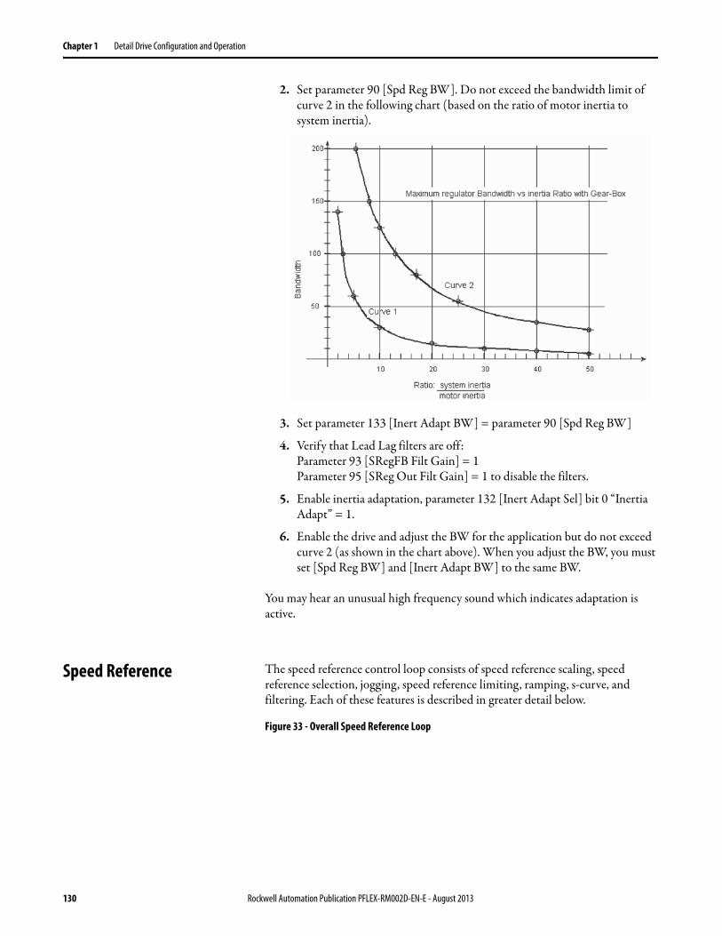
Chapter 1 Detail Drive Configuration and Operation
2. Set parameter 90 [Spd Reg BW]. Do not exceed the bandwidth limit of curve 2 in the following chart (based on the ratio of motor inertia to system inertia).
3. Set parameter 133 [Inert Adapt BW] = parameter 90 [Spd Reg BW]
4. Verify that Lead Lag filters are off:Parameter 93 [SRegFB Filt Gain] = 1Parameter 95 [SReg Out Filt Gain] = 1 to disable the filters.
5. Enable inertia adaptation, parameter 132 [Inert Adapt Sel] bit 0 “Inertia Adapt” = 1.
6. Enable the drive and adjust the BW for the application but do not exceed curve 2 (as shown in the chart above). When you adjust the BW, you must set [Spd Reg BW] and [Inert Adapt BW] to the same BW.
You may hear an unusual high frequency sound which indicates adaptation is active.
Speed Reference The speed reference control loop consists of speed reference scaling, speed reference selection, jogging, speed reference limiting, ramping, s-curve, and filtering. Each of these features is described in greater detail below.
Figure 33 - Overall Speed Reference Loop
130 Rockwell Automation Publication PFLEX-RM002D-EN-E - August 2013

Detail Drive Configuration and Operation Chapter 1
Speed Reference Scaling
The first section of the reference selection block is speed reference scaling. Both speed reference 1 and 2 have parameters associated with them to scale the values. See Figure 33.
Parameter 10 [Speed Ref 1] and parameter 12 [Speed Ref 2] are real parameters with units of per unit, where a value of 1 per unit equals base motor speed. Both [Speed Ref 1] and [Speed Ref 2] have their own scaling blocks.
The speed reference value in [Speed Ref 1] is divided by the scaling parameter 11 [Speed Ref1 Divide]. [Speed Ref1 Divide] cannot be changed while running, and cannot be linked to by another parameter.
The speed reference value for [Speed Ref 2] is multiplied by the scaling parameter 13 [Speed Ref2 Multi]. [Speed Ref2 Multi] is a linkable parameter. This allows speed reference 2 to be scaled “dynamically” with an input signal if desired. An example would be to have an analog input linked to the scale parameter. The
10
11
12
0
1
2
3
4
5
6
X
+13
14
15
16
0
17
1
0
157 00
0
30
31
32
33
34
Inv
Logic
1 00 1
157 01&
157 02
151 00
151 01
0
153 00
37
153 01
35
36
X38 +
21
61
140
141
144
142
143
151 1156
9
57
58
MaxX
1 40
1
152
0
4746
44
180
43
62
63
42
20
Speed Ref 1
Limit
Ramp S Curve
Spd Ref1 Divide
Speed Ref 2
Spd Ref2 Multi
Speed Ref 4
Speed Ref 5
Speed Ref DPI
Jog Speed 2
Speed Ref Sel
Applied LogicCmd Logic Ctrl State
Control Options
Applied LogicCmd
Logic
1 00 1
41
Rev Speed Limit
Fwd Speed Limit
Selected Spd Ref Limited Spd Ref
Inertia Comp
ΔnΔt
Friction CompInertia SpeedRef
InertiaAccelGain
InertiaDecelGain
Total Inertia
Logic Command(Inertia Comp)
Logic Command(Frict Comp)
FricComp TorqAdd
FricComp Setup
FricComp Stick
FricComp Slip
FricComp Rated
145
59
45 Delayed Spd Ref
FricComp Spd Ref
Link
Link
Link
Spd Ref Bypass
Control Options(SRef Filt En)
SpdRef Filt Gain
SpdRef Filt BW
Filtered Spd RefScaled Spd Ref
Spd Trim1 SpdRef
Speed Trim 1
S Curve Spd Ref
Speed Ref Scale
from ProcessControl [5G2]
Link
Virtual Encoder4x internal
Virt Encoder PPR
Virt Encdr Posit
Virt Encdr Dlyed
Ramped Spd Ref
S Curve Time
Accel Time
Decel TimeLogic Command(SpdRamp Dsbl)
Logic Command(Spd S Crv En)
Logic Ctrl State(SRef Ramp En)
Logic Ctrl State(SRef SCrv En)
Inertia Torq Add
(Unipol Fwd) +1
(Unipol Rev) -1
to Speed Control- Regulator [3A2]
to TorqueControl [4B2]
to TorqueControl [4B1]
Delay
OneScan
Delay
OneScan
/
PI Output
60DeltaSpeedScale
152
151 10
18
0
18
152 23
Jog Speed 1
0
1
1
55
Speed Comp
Lead Lag
(kn * s)+ wns + wn
20 152 21
1
*
set the desired port inparam 691
*
10
11
12X
13
Speed Ref 1
Spd Ref1 Divide
Speed Ref 2
Spd Ref2 Multi
/
Rockwell Automation Publication PFLEX-RM002D-EN-E - August 2013 131

Chapter 1 Detail Drive Configuration and Operation
speed reference and the scale would then affect the value sent to the reference select block.
Parameters 14 [Speed Ref 4], 15 [Speed Ref 5], and 20 [Speed Ref DPI] are in display units of RPM and do not have their own scaling blocks.
Speed Reference Select
Parameter 16 [Speed Ref Sel] selects which one of the seven input signals is acknowledged as the reference. [Speed Ref Sel] could be changed through a controller or through a digital input (see Digital Inputs for an example).
[Speed Ref Sel] can be set to the following values:
The source of parameter 20 [Speed Ref DPI] is selected by parameter 691 [DPI Ref Select]. [DPI Ref Select] can be set to one of the following: 1 - “Local HIM”, 2 - “Ext DPI Conn”, 3 - Aux DPI Conn”, or 5- Int DPI Conn.” 4 - “Reserved” is not used.
Setting Description
0 - Zero Speed Zero Speed is selected as the speed reference.
1 - Spd Ref 1 [Speed Ref 1] is selected as the speed reference.
2 - Spd Ref 2 [Speed Ref 2] is selected as the speed reference.
3 - Spd Ref 3 The sum of [Speed Ref 1] and [Speed Ref 2] is selected as the speed reference. Note that there is no "Speed Ref 3" parameter.
4 - Spd Ref 4 [Speed Ref 4] is selected as the speed reference.
5 - Spd Ref 5 [Speed Ref 5] is selected as the speed reference.
6 - Spd Ref DPI [Speed Ref DPI] is selected as the speed reference.
10
11
12
0
1
2
3
4
5
6
X
+13
14
15
16
0
20
Speed Ref 1
Spd Ref1 Divide
Speed Ref 2
Spd Ref2 Multi
Speed Ref 4
Speed Ref 5
Speed Ref DPI
Speed Ref Sel
/
*
132 Rockwell Automation Publication PFLEX-RM002D-EN-E - August 2013

Detail Drive Configuration and Operation Chapter 1
Jog Reference
Two separate jog speeds can be used as a speed reference - parameter 17 [ Jog Speed 1] or 18 [ Jog Speed 2]. For more information on jog speeds see Jog.
Stop Command
When a stop command is issued, parameter 157 [Logic Ctrl State] bit 0 - “Spd Ref En” is set to 0, causing a zero speed to be selected. When [Logic Ctrl State] bit 0 is set to 1, the selected speed or jog reference is used.
Direction Control and Bipolar Reference
The direction of rotation of the motor can be controlled by a forward/reverse command or by the use of a bipolar signal. For more information on direction control, see Direction Control and Bipolar Reference on page 47.
Speed Limits
The next section sets the forward and reverse speed limits for the speed reference. Parameter 31 [Fwd Speed Limit] sets the positive speed limit, in RPM. Parameter 30 [Rev Speed Limit] sets the negative speed limit, in RPM. Parameter 41 [Limited Spd Ref ] contains value, in RPM, of the limited speed reference.
1
0
157 00
0
Logic Ctrl State
30
31
Limit
41
Rev Speed Limit
Fwd Speed Limit
Limited Spd Ref
Rockwell Automation Publication PFLEX-RM002D-EN-E - August 2013 133
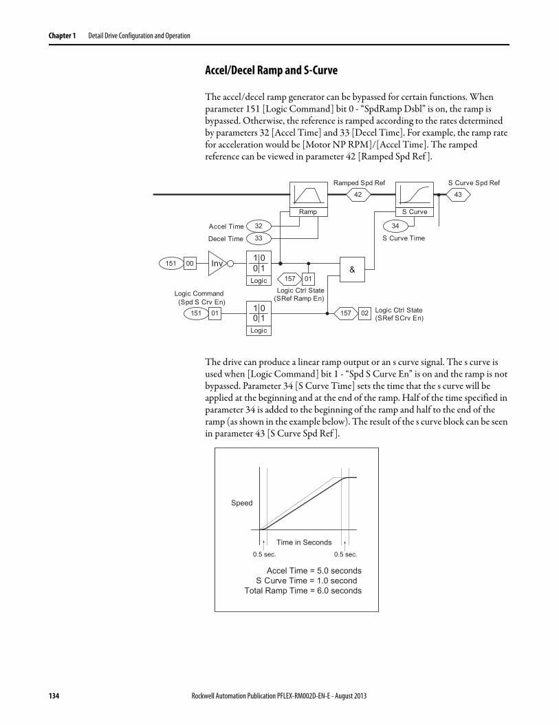
Chapter 1 Detail Drive Configuration and Operation
Accel/Decel Ramp and S-Curve
The accel/decel ramp generator can be bypassed for certain functions. When parameter 151 [Logic Command] bit 0 - “SpdRamp Dsbl” is on, the ramp is bypassed. Otherwise, the reference is ramped according to the rates determined by parameters 32 [Accel Time] and 33 [Decel Time]. For example, the ramp rate for acceleration would be [Motor NP RPM]/[Accel Time]. The ramped reference can be viewed in parameter 42 [Ramped Spd Ref ].
The drive can produce a linear ramp output or an s curve signal. The s curve is used when [Logic Command] bit 1 - “Spd S Curve En” is on and the ramp is not bypassed. Parameter 34 [S Curve Time] sets the time that the s curve will be applied at the beginning and at the end of the ramp. Half of the time specified in parameter 34 is added to the beginning of the ramp and half to the end of the ramp (as shown in the example below). The result of the s curve block can be seen in parameter 43 [S Curve Spd Ref ].
32
33
34
Inv
Logic
1 00 1
157 01&
157 02
151 00
151 01
4342
Ramp S Curve
Logic
1 00 1
S Curve Spd RefRamped Spd Ref
S Curve Time
Accel Time
Decel Time
Logic Command(Spd S Crv En)
Logic Ctrl State(SRef Ramp En)
Logic Ctrl State(SRef SCrv En)
S Curve Time = 1.0 second
Speed
Time in Seconds0.5 sec.
Accel Time = 5.0 seconds
Total Ramp Time = 6.0 seconds
0.5 sec.
134 Rockwell Automation Publication PFLEX-RM002D-EN-E - August 2013

Detail Drive Configuration and Operation Chapter 1
Speed Reference Bypass and Delayed Speed Reference
By default, parameter 37 [Spd Ref Bypass] is linked to [S Curve Spd Ref ]. However, if you wish to bypass the rest of the speed reference control loop, [Spd Ref Bypass] gives the capability to link to other parameters.
Parameter 45 [Delayed Spd Ref ] is delayed by one scan of the speed control loop. [Spd Ref Bypass] can be linked to [Delayed Spd Ref ] instead of [S Curve Spd Ref ] for use in SynchLink applications. See SynchLink on page 160 for more details.
Inertia Compensation
Inertia compensation is used to calculate the level of torque required due to load inertia during speed changes. For more information on inertia compensation, see Inertia Compensation on page 68.
Friction Compensation
The friction compensation block is used to calculate breakaway torque and the torque needed just to keep the motor running at a constant speed due to friction. For more information on friction compensation, see Friction Compensation on page 64.
Virtual Encoder
The virtual encoder block generates a position counter based on the speed reference in [S Curve Spd Ref ]. Parameter 61 [Virt Encoder PPR] is used to specify the desired pulses per revolution for the virtual encoder. The virtual encoder block will count at a rate of 4 times [Virt Encoder PPR] per one revolution of the motor. For example, if [Virt Encoder PPR] is 1024, the virtual encoder block will count at a rate of 4096 units per one revolution of the motor.
Parameter 62 [Virt Encdr Posit] is a 32 bit integer that contains the pulse count output of the virtual encoder block. This parameter is used for position follower applications (see the Follower section of the Position Loop).
43
45Delayed Spd Ref
LinkSpd Ref BypassS Curve Spd Ref
Delay
OneScan
37
Rockwell Automation Publication PFLEX-RM002D-EN-E - August 2013 135

Chapter 1 Detail Drive Configuration and Operation
Parameter 63 [Virt Encdr Dlyed] is a 32 bit integer that contains the pulse count output of the virtual encoder block delayed by one scan of the speed reference loop. This parameter can be used to send a virtual position reference over SynchLink for position follower applications.
Speed Reference Filter
A lead lag filter can be turned on by setting parameter 153 [Control Options] bit 1 - “Sref Filt En” on. Parameter 35 [SpdRef Filt Gain] sets the gain for the filter and parameter 36 [SpdRef Filt BW] sets the bandwidth for the filter.
Speed Reference Scale
The speed reference value up to this point is multiplied by the scaling parameter 38 [Speed Ref Scale]. [Speed Ref Scale] is applied to all of the selected speed references, as opposed to the specific scaling parameters for speed reference 1 and 2. [Speed Ref Scale] is a linkable parameter. This allows the speed reference value to be scaled “dynamically” with an input signal if desired. An example would be to have an analog input linked to the scale parameter. The speed reference and the scale would then affect the value sent to the speed regulator.
61
43 62
63
S Curve Spd Ref
Virtual Encoder4x internal
Virt Encoder PPR
Virt Encdr Posit
Virt Encdr Dlyed
Delay
OneScan
153 01
35
36
44
Control Options(SRef Filt En)
SpdRef Filt Gain
SpdRef Filt BW
Filtered Spd Ref
Lead Lag
(kn * s)+ wns + wn
X38
46
Scaled Spd Ref
Speed Ref Scale
136 Rockwell Automation Publication PFLEX-RM002D-EN-E - August 2013

Detail Drive Configuration and Operation Chapter 1
Speed Trim 1
At this point in the speed reference control loop, parameter 21 [Speed Trim 1] is added to the speed reference. By default, [Speed Trim 1] is linked to the output of the Process PI loop. The resulting parameter 47 [Spd Trim1 SpdRef ] is sent into the speed regulator loop.
Speed/Position Feedback The speed feedback block selects the feedback device and scales the feedback signal. This section will describe in detail how each of these functions operates.
Feedback Device
Parameter 222 [Motor Fdbk Sel] selects the feedback device for motor speed and position feedback. The possible settings for [Motor Fdbk Sel] are:
• 0 - “Encoder 0"• 1 - “Encoder 1"• 2 - “Sensorless”• 3 - “Reserved” (this setting is not used)• 4 - “Motor Sim”• 5 - “FB Opt Port0”• 6 - “FB Opt Port1”
Parameter 223 [Mtr Fdbk Alt Sel] selects an alternate feedback device when a feedback loss is detected on the primary device. The possible settings for [Mtr Fdbk Alt Sel] are the same as the possible settings for [Motor Fdbk Sel].
Speed regulation with a Feedback Sensor: 0.001% of Top Speed over a 100:1 Speed Range
Speed regulation sensorless: 0.5% of Top Speed Over a 120:1 typical Speed Range
Encoder
There are two encoder inputs on the standard I/O board of the PowerFlex 700S. They are located at TB2 - Row T (Top) and TB2 - Row B (Bottom). The encoder inputs are rated for Incremental, Dual Channel Quadrature type,
+
21
47
180
Spd Trim1 SpdRef
Speed Trim 1from ProcessControl
Link
to Speed Control- Regulator
PI Output
Rockwell Automation Publication PFLEX-RM002D-EN-E - August 2013 137

Chapter 1 Detail Drive Configuration and Operation
Isolated with differential transmitter Output (Line Drive). The encoder inputs can accept 5V DC or 12V DC. There is a 12V DC supply on the drive that can be used to supply power for the encoders. An external 5VDC power supply is required when the encoder requires a 5V DC supply.
An encoder offers the best performance for both speed and torque regulation applications. Encoder feedback is required for applications with high bandwidth response, tight speed regulation, torque regulation of (+/- 2%) or when the motor is required to operate at less than 1/100th its base speed.
[Encoderx PPR] sets the pulse per revolution rating of the encoder. This parameter has a range from 10 to 20000 PPR.
138 Rockwell Automation Publication PFLEX-RM002D-EN-E - August 2013

Detail Drive Configuration and Operation Chapter 1
[Encdrx Config] sets the configuration option for the encoder. The bits for [Encder x Config] are broken down as follows:
• Bit 0 - “Enc Filt bt0”• Bit 1 - “Enc Filt bt1”• Bit 2 - “Enc Filt bt2”• Bit 3 - “Enc Filt bt3”• Bit 4 - “Endr 4x”• Bit 5 - “Encdr A Phs”• Bit 6 - “Encdr Dir”• Bit 7 - “Reserved” (not used)• Bit 8 - “Reserved” (not used)• Bit 9 - “Edge Time”• Bit 10 - “Reserved” (not used)• Bit 11 - “Reserved” (not used)• Bit 12 - “SmplRate bt0”• Bit 13 - “SmplRate bt1”• Bit 14 - “SmplRate bt2”• Bit 15 - “SmplRate bt3”• Bits 16…31 - “Reserved” (not used)
The function of the bits in [Encdrx Config] is explained here.
• Bits 0 “Enc Filt bt0”, 1 “Enc Filt bt1”, 2 “Enc Filt bt2”, and 3 “Enc Filt bt3” configure encoder input filter (see Table 7 on page 140). The filter requires the input signal to be stable for the specified time period. Input transitions within the filter time setting will be ignored.
• Bits 4 “Encdr 4x” and 5 “Encdr A Phs” determine how the encoder channel A and B signals will be interpreted. Typically, both encoder phases A and B are used so that direction information is available. The parameter 230 [Encdr0 Position] counts up for forward rotation and down for reverse rotation. If bit 5 is set, then the B phase signal is ignored. As a result, the encoder position will only increase, regardless of rotation direction. Bits 4 and 5 together also determine the number of edges counted per encoder pulse (see Table 8 on page 140). “4x” sampling counts both rise and fall of both A and B encoder phases, hence 4 edges per pulse. In 4x mode, the encoder position will change by four times the encoder pulses per revolution rating (PPR) per encoder revolution (for example, it increments the value in parameter 230 [Encdr0 Position] by 4096 for one revolution of a 1024 PPR encoder).
• Bit 6 “Encdr Dir” inverts the channel A input, thus reversing the direction of the feedback.
Rockwell Automation Publication PFLEX-RM002D-EN-E - August 2013 139

Chapter 1 Detail Drive Configuration and Operation
• Bit 9 “Edge Time” configures the method of sampling used by the Velocity Position Loop (VPL). Setting the bit chooses “Edge to Edge” sampling, while resetting the bit to zero chooses “Simple Difference” sampling. “Simple Difference” sampling calculates speed by examining the difference between pulse counts over a fixed sample time. “Edge to Edge” sampling adjusts the sample time to synchronize with the position count updates from the daughter card - improving the accuracy of the speed calculation.
• Bits 12 “SmplRate bt0” through 15 “SmplRate bt3” configure the sample interval for measuring speed (see Table 7 on page 140). Increasing the encoder sample interval improves speed measurement near zero speed. Decreasing allows the speed control regulator to perform with high gains at high speeds.
Table 7 - Encoder Input Filter Settings
Table 8 - Multiplier and Direction Settings
Bit 3 2 1 0 Encoder Bit Filter Settings
0 0 0 0 Filter disabled
0 0 0 1 100 ns filter
0 0 1 0 200 ns filter
0 0 1 1 300 ns filter
0 1 0 0 400 ns filter
0 1 0 1 500 ns filter
0 1 1 0 600 ns filter
0 1 1 1 700 ns filter
1 0 0 0 800 ns filter (default setting)
1 0 0 1 900 ns filter
1 0 1 0 1000 ns filter
1 0 1 1 1100 ns filter
1 1 0 0 1200 ns filter
1 1 0 1 1300 ns filter
1 1 1 0 1400 ns filter
1 1 1 1 1500 ns filter
Bit 5 4 Mult. Directions Comments
0 0 2x fwd/rev Counts rise/fall of phase A, phase B only used to find direction
0 1 4x fwd/rev Counts rise/fall of both A and B phases (default setting)
1 0 1x fwd only Counts rise of phase A. Phase B ignored.
1 1 2X fwd only Counts rise of phase A. Phase B ignored.
140 Rockwell Automation Publication PFLEX-RM002D-EN-E - August 2013

Detail Drive Configuration and Operation Chapter 1
Table 9 - Encoder Sample Interval Settings
[Encdrx Error] indicates the error status of the encoder when there is an error. The bits for [Encdrx Error] are broken down as follows:
• Bit 0 - “EncdrMissing”• Bit 1 - “Quad Loss”• Bit 2 - “Phase Loss”• Bit 3 - “Phase Level”
The encoder block generates speed feedback, seen in [Encdrx Spd Fdbk]. [Encdrx Spd Fdbk] is in units of RPM.
The encoder block also generates a position feedback, seen in [Encdrx Position]. [Encdrx Position] is in counts.
Bit 15 14 13 12 Encoder Sample Interval Settings
0 0 0 0 0.5 ms
0 0 0 1 0.5 ms (min. setting)
0 0 1 0 1.0 ms
0 0 1 1 1.5 ms
0 1 0 0 2.0 ms (default setting)
0 1 0 1 2.5 ms
0 1 1 0 3.0 ms
0 1 1 1 3.5 ms
1 0 0 0 4.0 ms
1 0 0 1 4.5 ms
1 0 1 0 5.0 ms
1 0 1 1 5.5 ms
1 1 0 0 6.0 ms (max. setting)
1 1 0 1 6.0 ms
1 1 1 0 6.0 ms
1 1 1 1 6.0 ms
231
230
233
232
234
Encoder 0
Processing
Encdr0 Spd Fdbk
Encdr0 PositionEncdr0 ErrorEncoder0 PPR
Encdr0 Config
Rockwell Automation Publication PFLEX-RM002D-EN-E - August 2013 141

Chapter 1 Detail Drive Configuration and Operation
Sensorless
Sensorless mode is used when zero speed or more than a 120:1 speed range is not required.
Parameter 548 [Est Speed Fdbk] contains the estimated motor speed, used when sensorless mode is selected. The estimated speed feedback is based on voltage feedback from the motor. [Est Speed Fdbk] is scaled so that a value of 4096 equals parameter 4 [Motor NP RPM].
The estimated speed feedback is converted to RPM, which can be seen in parameter 74 [Motor Spd Est].
Parameter 75 [MtrSpd Est Posit] is an estimated position for sensorless mode. It is calculated based on [Est Speed Fdbk] and the value in parameter 226 [Virtual Edge/Rev]. [Virtual Edge/Rev] is a user defined value for the number of pulses per motor revolution.
Motor Simulator
The simulator mode allows the drive to be operated without a motor connected and is meant for demo purposes only. If a motor is connected with this mode selected very erratic and unpredictable operation will occur.
Parameter 76 [MtrSpd Simulated] contains the simulated speed feedback and is scaled in units of RPM.
Parameter 70 [MtrSpd Sim Posit] contains the simulated position feedback. It is calculated based on the simulated speed feedback and the value in [Virtual Edge/Rev]. [Virtual Edge/Rev] is a user defined value for the number of pulses per motor revolution.
548 74
75AccumΣ
Motor Spd Est
226Virtual Edge/Rev
/4096
Est Speed Fdbk
MtrSpd Est Posit
76
70
MotorSimulator
Spd Calc
MtrSpd Simulated
MtrSpd Sim PositAccumΣ
226Virtual Edge/Rev
142 Rockwell Automation Publication PFLEX-RM002D-EN-E - August 2013

Detail Drive Configuration and Operation Chapter 1
Feedback Option Cards
There are three different feedback option cards that can be installed on the PowerFlex 700S:
• The Hi-Resolution Encoder Feedback Option Card
• The Resolver Feedback Option Card
• The Multi Device Interface (MDI) Option Card
Only one of the option cards above can be physically installed on the drive at a time. When the Hi-Resolution encoder option or Resolver option are installed, their data is processed by feedback option card port 0. When the MDI option is installed, it has a Hi-Resolution encoder processed by feedback option card port 0 and a Temposonics linear sensor processed by feedback option card port 1.
Parameter 251 [FB Opt0 Spd Fdbk] contains the speed feedback from either the Hi-Resolution Encoder or the Resolver connected at port 0.
Parameter 250 [FB Opt0 Posit] contains the position feedback from either the Hi-Resolution Encoder or the Resolver connected at port 0.
Parameter 277 [FB Opt1 Spd Fdbk] contains the speed feedback from the Temposonics linear sensor when the MDI option is installed.
Parameter 276 [FB Opt1 Posit] contains the position feedback from the Temposonics linear sensor when the MDI option is installed.
Parameter 249 [Fdbk Option ID] displays information about the feedback option installed in feedback option card port 0. This information is read from the feedback option card. Bits 15…11 will be a value of 2000 hex for an old hi-resolution option card and a value of 2020 hex for a new hi-resolution option card.
251
250
249
FeedbackOption Card 0
Processing
259
266
270
271
272
273
274
260
267
Hi Res0 Config
Reslvr0 Config
Fdbk Option ID
Rslvr0 Spd Ratio
Reslvr0 Carrier
Reslvr0 In Volts
Rslvr0 XfrmRatio
Reslvr0 CableBal
Hi Res0 Status
Reslvr0 Status
FB Opt0 Spd Fdbk
FB Opt0 Posit
277
276
FB Opt1 Spd Fdbk
FB Opt1 Posit
Rockwell Automation Publication PFLEX-RM002D-EN-E - August 2013 143

Chapter 1 Detail Drive Configuration and Operation
Hi-Resolution Encoder Feedback Option
The position feedback (seen in [FB Opt0 Posit]) from a Hi-Resolution Encoder counts at a rate of 1,048,576 counts per motor revolution.
Parameter 259 [Hi Res0 Config] is used to configure the Hi-Resolution Encoder. • Bit 5 “Hi Res Dir” determines counting direction. If clear, direction is
forward or up. If set, the direction is reverse or down.• Bits12 “SmplRate baits “SmplRate bt3” configure the sample interval for
measuring speed (see Table 10). Increasing the encoder sample interval improves speed measurement near zero speed. Decreasing allows the speed control regulator to perform with high gains at high speeds.
• The remaining bits are reserved (not used).
Table 10 - Encoder Sample Interval
Parameter 260 [Hi Res0 Status] indicates faults on the Hi-Resolution Encoder Feedback Option.
• Bit 8 “Open Wire” indicates an open wire fault.• Bit 9 “Power Fail” indicates the failure of the power supply.• Bit 10 “Diag Fail” indicates the option board failed its power-up diagnostic
test.• Bit 11 “Msg Checksum” indicates a message checksum fault.• Bit 12 “Time Out Err” indicates a RS-485 time-out fault.• The remaining bits are reserved (not used).
Bit 15 14 13 12 Encoder Sample Interval Settings
0 0 0 0 0.5 ms
0 0 0 1 0.5 ms (min. setting)
0 0 1 0 1.0 ms
0 0 1 1 1.5 ms
0 1 0 0 2.0 ms (default setting)
0 1 0 1 2.5 ms
0 1 1 0 3.0 ms
0 1 1 1 3.5 ms
1 0 0 0 4.0 ms
1 0 0 1 4.5 ms
1 0 1 0 5.0 ms
1 0 1 1 5.5 ms
1 1 0 0 6.0 ms (max. setting)
1 1 0 1 6.0 ms
1 1 1 0 6.0 ms
1 1 1 1 6.0 ms
144 Rockwell Automation Publication PFLEX-RM002D-EN-E - August 2013

Detail Drive Configuration and Operation Chapter 1
Resolver Feedback Option
Parameter 266 [Reslvr0 Config] is used to configure the resolver feedback option.
Setting bit 0 “Cable Tune” enables the cable tuning test, resetting the bit to zero disables the test. This test automatically runs on power up to measure the IR drop in the resolver cable.
• Bit 1 “Reserved” (not used)• Bits 2 “Resolution 0" and bit 3 “Resolution 1" select the resolver resolution
(see Table 11).• Setting bit 4 “Energize” energizes the resolver, resetting the bit to zero de-
energizes it.• Bit 5 “Resolver Dir” determines counting direction. If clear, direction is
forward or up. If set, the direction is reverse or down.• Bit 9 “Reserved” (not used)• Bits 10 “Reserved” (not used)• Bits 12…15 “SmplRate bt 0” - “SmplRate bt3” configure the sample
interval for measuring speed (refer to Table 12). Increasing the resolver sample interval improves speed measurement near zero speed. Decreasing the resolver sample interval allows the speed control regulator to perform with high gains at high speeds.
Table 11 - Resolution Settings
Bit 3 2 Resolution Setting
0 0 10 bit
0 1 12 bit (default setting)
1 0 14 bit
1 1 16 bit
Rockwell Automation Publication PFLEX-RM002D-EN-E - August 2013 145

Chapter 1 Detail Drive Configuration and Operation
Table 12 - Resolver Sample Interval
Parameter 270 [Reslvr0 SpdRatio] specifies the speed ratio for the resolver option card at port 0. The speed ratio comes from the following formula.
Speed ratio = electrical revolutions / mechanical revolutions = pole count / 2.
Parameter 271 [Reslvr0 Carrier] specifies the resolver carrier frequency for the resolver option card at port 0.
Parameter 272 [Reslvr0 In Volts] specifies the resolver input voltage for the resolver option card at port 0.
Parameter 273 [Rslvr0 XfrmRatio] specifies the resolver transform ratio for the resolver option card at port 0.
Parameter 274 [Reslvr0 CableBal] specifies the resolver cable balance for the resolver option card at port 0.
Bit 15 14 13 12 Resolver Sample Interval Settings
0 0 0 0 0.5 ms
0 0 0 1 0.5 ms (min. setting)
0 0 1 0 1.0 ms
0 0 1 1 1.5 ms
0 1 0 0 2.0 ms (default setting)
0 1 0 1 2.5 ms
0 1 1 0 3.0 ms
0 1 1 1 3.5 ms
1 0 0 0 4.0 ms
1 0 0 1 4.5 ms
1 0 1 0 5.0 ms
1 0 1 1 5.5 ms
1 1 0 0 6.0 ms (max. setting)
1 1 0 1 6.0 ms
1 1 1 0 6.0 ms
1 1 1 1 6.0 ms
146 Rockwell Automation Publication PFLEX-RM002D-EN-E - August 2013

Detail Drive Configuration and Operation Chapter 1
Parameter 267 [Reslvr0 Status] indicates status of the resolver option card port 0.• Bit 0 “Cable Status” indicates that the cable tuning test is in progress.• Bit 1 “Tune Result” indicates the tuning parameter type. When set, it
indicates the tuning is using the parameter database. When cleared, it indicates the tuning is using derived data.
• Bit 2 “Mtr Turning” indicates that the motor is turning.• Bit 3 “Cable Comp” • Bit 4 “Energized” indicates the resolver is energized.• Bit 8 “Open Wire” indicates a problem with the cable (open circuit).• Bit 9 “Power Supply” indicates problem with the option card's power
supply.• Bit 10 “Diag Fail” indicates the option card has failed its power-up
diagnostics.• Bit 11 “Select OK”
Motor Position Feedback
The motor position feedback is selected according to the feedback device selection. The value for motor position feedback appears in parameter 762 [Mtr Posit Fdbk]. [Mtr Posit Fdbk] is in counts. From there, the position feedback enters the position control loop.
Rockwell Automation Publication PFLEX-RM002D-EN-E - August 2013 147

Chapter 1 Detail Drive Configuration and Operation
Motor Speed Feedback and Scaled Speed Feedback
The motor speed feedback is selected according to the feedback device selection. The value for motor speed feedback appears in parameter 300 [Motor Spd Fdbk]. [Motor Spd Fdbk] is in RPM. From there, the speed feedback enters the speed regulation loop. The filter for the speed feedback is shown in the speed regulation loop section.
Branching off of the motor speed feedback, there is a low pass filter. This low pass filter filters out high frequency before displaying the speed feedback on the HIM.
Parameter 72 [Scaled Spd Fdbk] provides a user scalable speed feedback. It is multiplied by the value in parameter 73 [Spd Fdbk Scale].
Speed Feedback Loss Ride Through
The speed feedback loss ride through function provides an automatic switch over from the primary motor speed feedback device to the alternate motor speed feedback device when a primary motor speed feedback device fault is sensed. If the alternate speed feedback device has failed the switching will not be allowed and the drive will fault. The active device can be monitored and manual switching between the primary and alternate devices is available. This function has also been referred to as tach loss switch over and encoder loss ride through.
The drive determines that the encoder has faulted based on a combination of hardware detection and monitoring the rate of change of the motor speed. The hardware fault detection is based on illegal encoder states and improper encoder switching patterns. The rate of change of motor speed detection is determined by a rate of change greater than a user-defined speed change.
Hardware detection of feedback loss for the feedback option cards is based on the type of device used and specific fault detection implemented on the feedback option card. The rate of change of motor speed detection is the same implementation as for encoder feedback.
LPass
Filter X
300
73
72
Motor Spd Fdbk
Spd Fdbk Scale
Scaled Spd Fdbk
to SpeedControl [3A4]
To HIM Display
148 Rockwell Automation Publication PFLEX-RM002D-EN-E - August 2013

Detail Drive Configuration and Operation Chapter 1
Speed feedback loss ride through is not allowed in position mode. If the encoder loss ride through function was allowed in a positioning system it is likely that the alternate feedback device will supply an arbitrary position feedback value when an encoder loss is detected. This, in turn, could result in unintended motion in the drive system.
Speed Feedback Loss Ride Through Configuration
Parameter 151 [Logic Command] bit 2, “TackLoss Rst” provides a manual switch between primary and alternate speed feedback devices with a “0” to “1” bit transition. A transition from “1” to “0” does not cause a change in operation.
Parameter 152 [Applied LogicCmd] bit 2, “TachLoss Rst” shows the status of parameter 151 [Logic Command] bit 2 “TachLoss Rst” switch.
Setting parameter 153 [Control Options], bit 16 “Auto Tach Sw” to a value of “1” enables the automatic switching of speed feedback devices when a failure is detected. A value of “0” disables the automatic switching of speed feedback devices. Only automatic switching from the primary device specified in parameter 222 [Mtr Fdbk Sel Pri] to the alternate device specific in parameter 223 [Mtr Fdbk Sel Alt] is available. Switching from the alternate to the primary device must be done manually by setting parameter 151 [Logic Command], bit 2 “TackLoss Rst” from “0” to “1”.
Parameter 155 [Logic Status] bit 12, “Tach Loss Sw,” shows which speed feedback device is currently active. A value of “0” in bit 12 indicates that the primary speed feedback device selected in [Mtr Fdbk Sel Pri] is active. A value of “1” in bit 12 indicates that the alternate speed feedback device selected in [Mtr Fdbk Sel Alt] is active.
Parameter 222 [Mtr Fdbk Sel Pri] selects the primary speed feedback device. It is not intended to use the sensorless selection as the primary (or active) speed feedback device as there is no feedback loss detection used with sensorless operation.
Parameter 223 [Mtr Fdbk Sel Alt] selects the alternate speed feedback device. Any selection of feedback devices, including sensorless operation is available providing a corresponding motor type and associated feedback device is present.
IMPORTANT Even though the encoder loss ride through function attempts to automatically switch feedback devices with minimum disturbance, a system disturbance will occur. In some cases feedback device degradation may occur before complete failure takes place. The user must determine if the encoder loss ride through function is appropriate for each application.
Rockwell Automation Publication PFLEX-RM002D-EN-E - August 2013 149

Chapter 1 Detail Drive Configuration and Operation
Settings for parameter 222 [Mtr Fdbk Sel Pri] and parameter 223 [Mtr Fdbk Sel Alt]:
Parameter 224 [TachSwitch Level] sets the detection level for the automatic speed loss switch over routine. A drop in feedback speed at the percent of rated speed over a 0.5 ms interval will cause a tach switch from primary to alternate device. Setting this level lower will make the speed detection more sensitive and lower the minimum speed at which a speed switch could occur. Setting this level higher will make the speed switch less sensitive and raise the minimum speed for speed switch detection.
Parameter 320 [Exception Event1] bits 2 through 5 show the error status of the corresponding speed feedback device.
Parameter 365 [Fdbk LsCnfg Pri] and parameter 366 [Fdbk LsCnfg Alt] set the feedback loss configuration for each feedback device. The primary feedback device should be configured to 1 “Alarm”. The alternate feedback device should typically be configured to 2 “FltCoastStop”.
Settings for [Fdbk LsCnfg Pri] and [Fdbk LsCnfg Alt]:
Parameter 510 [FVC Mode Config] bit 22 “SrLss RdThru” must be set to “1” if sensorless operation is selected in [Mtr Fdbk Sel Alt]. In all other cases Parameter 510 bit 22 should be set to “0”.
Speed Feedback Loss Ride Through Operation
Setting up the feedback loss ride through function requires the following steps:
1. Enter a valid feedback device selection in parameter 222 [Mtr Fdbk Sel Pri].
2. Enter a valid feedback device selection in parameter 223 [Mtr Fdbk Sel Alt].
3. Setting parameter 365 [Fdbk LsCnfg Pri] to 1 “Alarm.”
4. Setting parameter 366 [Fdbk LsCnfg Alt] to 2 “FltCoastStop” (recommended but not necessary).
0 = Encoder 0 3 = Reserved
1 = Encoder 1 4 = Motor Sim
2 = Sensorless 5 = FB Opt Port0
2 = Encdr0 Loss
3 = Encdr1 Loss
4 = FB Opt0 Loss
5 = FB Opt1 Loss
1 = Alarm
2 = FltCoastStop
150 Rockwell Automation Publication PFLEX-RM002D-EN-E - August 2013

Detail Drive Configuration and Operation Chapter 1
5. Setting the speed change detection level in parameter 224 [TachSwitch Level].
6. Setting parameter 153 [Control Options] bit 16 “Auto Tach Sw” to 1 for automatic switch over.
7. Setting parameter 510 [FVC Mode Config] bit 22 “SrLssRdThru” to 1 when sensorless operation is selected in parameter 223.
Automatic and manual switching of feedback devices is inhibited if a loss in parameter 320 [Exception Event1] bits 2…4 (as appropriate) is sensed on the device to which switching was to take place. The drive will fault when it is configured for speed feedback loss ride through and the primary device fails when the alternate device has failed and is also configured to fault. If the alternate device is not configured to fault, then switching to the alternate device will be inhibited and operation on the primary feedback device will continue. Note that operation on the primary device will continue even with that device's failure since that fault must be configured for an alarm to allow for automatic device switch over.
Manual Speed Feedback Device Switching
Parameter 151 [Logic Command] bit 2, “TackLoss Rst,” provides a manual switch between active and non-active primary or alternate speed feedback devices with a “0” to “1” bit transition. Resetting bit 2 from a “1” to a “0” causes no change in operation. The switch is between the active feedback device (either primary or alternate) to the non-active device. For example, if prior to the reset the alternate device selected in Parameter 223 [Mtr Fdbk Sel Alt] is active, then after the reset the primary feedback device selected in Parameter 222 [Mtr Fdbk Sel Pri] will be used as the active speed feedback device. The reset activation is prohibited if a failure is sensed in the speed feedback device to which the drive is switching. The active device selection command is shown in parameter 152. Manual switching between primary and alternate devices can be made while the drive is running.
FdbkLossDetect
300
Logic Command(TachLoss Rst)
Motor Spd Fdbkto SpeedRegulator
0
1
151 2
155 12
153 16
Control Options
Speed Feedbackfrom Primary Device
Speed Feedbackfrom Alternate Device
(AutoTach Sw)
Logic Status(Tach Loss Sw)
Rockwell Automation Publication PFLEX-RM002D-EN-E - August 2013 151

Chapter 1 Detail Drive Configuration and Operation
Speed/Torque Select The Speed/Torque Mode Select parameter is used to choose the operating mode for the drive. The drive can be programmed to operate as a velocity regulator, a torque regulator, or a combination of the two. See the firmware flowchart shown in Figure 34 on page 152Figure 34 -.
Figure 34 - Firmware Flowchart
As shown in Figure 34, parameter 110 [Spd/Trq Mode Sel], is used to select the mode of operation. Zero torque current is allowed when set to zero (0).
Set to a value of 1, the drive and motor are operated in speed mode. The torque command changes as needed to maintain the desired speed.
Set [Spd/Trq Mode Sel] to a value of two (2) for torque mode. In torque regulation mode, the drive controls the desired motor torque. The motor speed is the result of torque command and load present at the motor shaft.
Min and Max mode are selected by values three (3) and four (4) respectively. These modes offer a combination of speed and torque operation. The algebraic minimum or maximum of speed/torque will be the operating point for the Min and Max modes. The drive automatically switches from speed to torque mode (or from torque to speed) based on the dynamics of the motor/load.
The Min mode is typically used with positive torque and forward speed operation, the minimum of the two being closest to zero. The Max mode is opposite, typically used with reverse speed and negative torque, the maximum being the least negative (closest to zero).
Sum mode is selected when [Spd/Trq Mode Sel] is set to a value of 5. This mode allows an external torque command to be added to the speed regulator output when desired.
Speed Regulation Mode
Operating as a speed regulator is the most common and simplest mode to set up. Examples of speed regulated applications are blowers, conveyors, feeders, pumps, saws, and tools.
59
302
145Min
Max
AbsMin
0
1
2
3
4
5
6
111
X
112
113
114
115
Spd Reg PI Out[3H4]
FricComp TorqAdd[2H3]
Inertia Torq Add[2H4]
Torque Ref 1
Torq Ref1 Div
Torque Ref 2
Torq Ref2 Multi
Torque Trim
Spd/Torq ModeSel
0
0
1
157 10
116Torque Step
Logic Ctrl State(Forced Spd)
from Speed Control
/
++
++
+
++
+
++
110
152 Rockwell Automation Publication PFLEX-RM002D-EN-E - August 2013

Detail Drive Configuration and Operation Chapter 1
In a speed regulated application, the speed regulator output generates the torque reference. Note that under steady state conditions the speed feedback is steady while the torque reference is a constantly adjusting signal. This is required to maintain the desired speed. In a transient state, the torque reference changes dramatically to compensate for a speed change. A short duration change in speed is the result of increasing or decreasing the load very rapidly.
Inertia Torque Add and Friction Compensation Torque Add are summed with the output of the speed regulator. See Friction Compensation on page 64 and Inertia Compensation on page 68.
Torque Regulation Mode
A torque regulated application can be described as any process requiring some tension control. An example is a winder or unwinder with material being “drawn” or pulled with a specific tension required. The process requires another element setting the speed. Configuring the drive for torque regulation requires[Spd/Trq Mode Sel] to be set to 2. In addition, a reference signal must be linked to the Torque Reference. If an analog signal is used for the reference, link parameter 800 [Anlg In1 Data] to parameter 111 [Torque Ref 1].
When operating in a torque mode, the motor current will be adjusted to achieve the desired torque. If the material being wound/unwound breaks, the load will decrease dramatically and the motor can potentially go into a “runaway” condition.
Torque Reference:• Parameter 111 [Torque Ref 1] is divided by parameter 112 [Torq Ref1
Div]• Parameter 113 [Torque Ref 2] is multiplied by parameter 114 [Torq Ref2
Mult]• Parameter 115 [Torque Trim] can be used to trim the torque. For example,
[Torque Trim] can be linked to an analog input or to the Process PI output.
The final torque reference, in the Torque Mode, is the sum of scaled [Torque Ref 1], scaled [Torque Ref 2], and [Torque Trim].
111
X
112
113
114
115
/
++
+
Torque Ref 1
Torq Ref1 Div
Torque Ref 2
Torq Ref2 Multi
Torque Trim
Rockwell Automation Publication PFLEX-RM002D-EN-E - August 2013 153

Chapter 1 Detail Drive Configuration and Operation
Min Mode / Max Mode
This operating mode compares the speed and torque commands. The algebraically minimum value is used. This mode can be thought of as a Speed Limited Adjustable Torque operation. Instead of operating the drive as a pure torque regulator, the “runaway” condition can be avoided by limiting the speed. A winder is a good example for the application of the Min Spd/Trq operating mode. Max mode would be used if both speed and torque are negative.
Figure 35 illustrates how min. mode operates. The drive starts out operating as a torque regulator. The torque reference causes the motor to operate at 308rpm. The speed reference is 468 rpm, so the minimum is to operate as a torque regulator. While operating in torque regulation, the load decreases and the motor speeds up. Notice the torque command has not changed. When the speed regulator comes out of saturation, it clamps the speed and now the drive operates as a speed regulator. The At Speed Relay then closes.
Figure 35 - Min Mode Operation
Sum Mode
Configuring the drive in this mode allows an external torque input to be summed with the torque command generated by the speed regulator. The drive requires both a speed reference and a torque reference to be linked. This mode can be used for applications that have precise speed changes with critical time constraints. If the torque requirement and timing is known for a given speed change, then the external torque input can be used to preload the integrator. The timing of the speed change and the application of an external torque command change must be coordinated for this mode to be useful. The sum mode will then work as a feed forward to the torque regulator.
154 Rockwell Automation Publication PFLEX-RM002D-EN-E - August 2013

Detail Drive Configuration and Operation Chapter 1
Zero Torque Mode
Operation in zero torque mode allows the motor to be fully fluxed and ready to rotate when a speed command or torque command is given. This mode can be used for a cyclical application where through put is a high priority. The control logic can select zero torque during the “rest” portion of a machine cycle instead of stopping the drive. When the cycle start occurs, instead of issuing a start to the drive, a speed regulate mode can be selected. The drive will then immediately accelerate the motor without the need for “flux up” time.
Note: Zero Torque may excessively heat the motor if operated in this mode for extended periods of time. No load or flux current is still present when the drive is operating in zero torque mode. A motor with an extended speed range or separate cooling methods (blower) may be required.
Absolute Min Mode
Absolute Min Mode selects the smallest absolute algebraic value to regulate to when the torque reference and torque generated from the speed regulator are compared.
Start Inhibits This section covers Start Inhibits, parameter 156 [Run Inhibit Stat]. This parameter indicates the cause of no response to a start request.
Bit 0 Description
0 Drive is Faulted
1 No Enable signal present
2 Software Ramp Stop request present
3 Software Coast Stop request present
4 Software Current Limit Stop request present
5 Power Loss
6 Power EE prom error
7 Flash upgrade in progress
8 Start request present
9 Jog request present
10 Encoder PPR error
11 Bus Precharge not complete
12 Digital input configuration error
13 Motin Shtdwn
14 Permanent Magnet motor Feedback Error
Rockwell Automation Publication PFLEX-RM002D-EN-E - August 2013 155

Chapter 1 Detail Drive Configuration and Operation
Start/Stop Modes Description
This section serves as a supplement to the PowerFlex 700S Drive User Manual, publication 20D-UM001, addressing items specific to the PowerFlex 700S start and stop modes.
Technical Information
The start and stop mode refers to how you want the drive's start and stop to be controlled. There are two basic modes of start and stop control: 3-wire and 2-wire.
3-wire control indicates that the start and stop are momentary inputs. 3-wire control also indicates that there is one input for the start command, and one input for the stop command. The term “3-wire” comes from the fact that when using this type of control with digital inputs, one wire is used for the start input, one wire is used for the stop input, and one wire is used for the common.
2-wire control indicates that the start and stop are combined as one maintained input. The input must be on to start and to remain running. Then the same input is turned off to stop. The term “2-wire” comes from the fact then when using this type of control with digital inputs, one wire is used for the combined start/stop input, and one wire is used for the common.
For the stop command, there are three different types of stopping that can be performed: coast stop, ramp stop, and current limit stop.
• Coast Stop - when in coast stop, the drive acknowledges the stop command by shutting off the output transistors and releasing control of the motor. The load/motor will coast or free spin until the mechanical energy is dissipated.
• Ramp Stop - when in ramp stop, the drive acknowledges the stop command by ramping down the motor speed reference using the programmed parameter 33 [Decel Time], maintaining control of the motor until the drive output reaches zero. The output transistors are then shut off.
• Current Limit Stop - when in current limit stop, the drive acknowledges the stop command by setting the motor speed reference to zero, causing the drive to bring the motor down to zero speed as fast as the power limits, torque limits and current limits will allow. When the drive output reaches zero, the output transistors are shut off.
When different stop types are commanded at the same time, the priority from highest priority to lowest is coast stop, current limit stop, and then ramp stop.
The remainder of this section describes how to configure the drive for the different start and stop modes.
156 Rockwell Automation Publication PFLEX-RM002D-EN-E - August 2013

Detail Drive Configuration and Operation Chapter 1
Configuring the Start and Stop for 3-Wire Control (Momentary Start and Stop)
To configure the drive for 3-wire control with a ramp stop:
For parameter 153 [Control Options], set bit 8 “3WireControl” to on (1) and set bits 3 “2WCurrLimStp” and 9 “2W CoastStop” to off (0).
To control from digital inputs:
1. Set parameter 839 [DigIn2 Sel] = 1 “Normal Stop” or = 5 “Stop - CF”. “Stop - CF” indicates that the same digital input is used as a stop and a clear fault.
2. Set parameter 840 [DigIn3 Sel] = 2 “Start”.
To control from a communication network:
1. To perform a ramp stop, toggle bit 0 “Normal Stop” in the logic command word on and then off.
2. To perform a start, toggle bit 1 “Start” in the logic command word on and then off.
To configure the drive for 3-wire control with a coast stop:
For parameter 153 [Control Options], set bit 8 “3WireControl” to on (1) and set bits 3 “2WCurrLimStp” and 9 “2W CoastStop” to off (0).
To control from digital inputs:
1. Set parameter 839 [DigIn2 Sel] = 10 “Coast Stop”
2. Set parameter 840 [DigIn3 Sel] = 2 “Start”
To control from a communication network:
1. To perform a coast stop, toggle bit 9 “Coast Stop” in the logic command word on and then off.
2. To perform a start, toggle bit 1 “Start” in the logic command word on and then off.
Rockwell Automation Publication PFLEX-RM002D-EN-E - August 2013 157

Chapter 1 Detail Drive Configuration and Operation
To configure the drive for 3-wire control with a current limit stop:
For parameter 153 [Control Options], set bit 8 “3WireControl” to on (1) and set bits 3 “2WCurrLimStp” and 9 “2W CoastStop” to off (0).
To control from digital inputs:
1. Set parameter 839 [DigIn2 Sel] = 9 “Current Limit Stop”
2. Set parameter 840 [DigIn3 Sel] = 2 “Start”
To control from a communication network:
1. To perform a current limit stop, toggle bit 8 “CurrLim Stop” in the logic command word on and then off.
2. To perform a start, toggle bit 1 “Start” in the logic command word on and then off.
Note: In 3-wire mode, all stops commanded from pressing the HIM stop button are ramp stops.
Configuring the Start and Stop for 2-Wire Control (Maintained Start and Stop)
To configure the drive for 2-wire control with a ramp stop:
For parameter 153 [Control Options], set bits 3 “2WCurrLimStp”, 8 “3WireControl”, and 9 “2W CoastStop” to off (0).
To control from digital inputs:
• Set parameter 839 [DigIn2 Sel] = 3 “Run”
To control from a communication network:
• To perform a ramp stop, toggle bit 1 “Start” in the logic command word on and then off.
To control from the HIM:
• Hold down the start button to run and release the start button to perform a ramp stop.
158 Rockwell Automation Publication PFLEX-RM002D-EN-E - August 2013

Detail Drive Configuration and Operation Chapter 1
To configure the drive for 2-wire control with a coast stop:
For parameter 153 [Control Options], set bit 9 “2W CoastStop” to on (1) and set bits 3 “2WCurrLimStp” and 8 “3WireControl” off (0).
To control from digital inputs:
• Set parameter 839 [DigIn2 Sel] = 3 “Run”
To control from a communication network:
• To perform a coast stop, toggle bit 1 “Start” in the logic command word on and then off.
To control from the HIM:
• Hold down the start button to run and release the start button to perform a coast stop.
Note: When P153 [Control Options] bit 9 is on, and bits 3 and 8 are off all other stop commands become coast stops because of the priority of the stop types. For example, if you try to command a ramp stop or current limit stop from a communication network, the drive will still perform a coast stop.
To configure the drive for 2-wire control with a current limit stop:
For parameter 153 [Control Options], set bits 3 “2WCurrLimStp” to on (1) and bits 8 “3WireControl” and 9 “2W CoastStop” to off (0).
To control from digital inputs:
• Set parameter 839 [DigIn2 Sel] = 3 “Run”
To control from a communication network:
• To perform a current limit stop, Toggle bit 1 “Start” in the logic command word on and then off.
To control from the HIM:
• Hold down the start button to run and release the start button to perform a current limit stop
Note: When parameter 153 [Control Options] bit 3 is on, and bits 8 and 9 are off the ramp (normal) stop becomes a current limit stop. For example, if you try to command a ramp stop from a communication network, the drive will still perform a current limit stop. A coast stop can still be performed by commanding a coast stop.
Rockwell Automation Publication PFLEX-RM002D-EN-E - August 2013 159

Chapter 1 Detail Drive Configuration and Operation
Start-Up See Autotune on page 17.
Stop Modes See Start/Stop Modes on page 156.
SynchLink This section contains information specific to PowerFlex 700S SynchLink parameters and gives an example of setting up the PowerFlex 700S SynchLink using DriveExecutive. See the SynchLink System Design Guide, publication 1756-TD008, for PowerFlex 700S SynchLink topologies, hardware, and wiring details.
Technical Information
SynchLink data is transmitted as a combination of direct and buffered data. The following table shows the different formats supported by the PowerFlex 700S for transmit/receive data and the respective SynchLink fiber update rates for the direct and buffered data.
SynchLink Configuration
Parameter 1000 [SL Node Cnfg] is broken down into 3 bits:• Bit 1 - “Time Keeper” - This bit is turned on in the SynchLink master.
Only one node in a SynchLink network can be the time keeper.• Bit 2 - “Reserved” - Not used.• Bit 3 - “Synch Now” - Selecting this bit enables the “Synch Now”
synchronization mode. This mode will cause the drive's system clock to synchronize to the time keeper as quickly as possible. Deselecting this bit enables the “Synch Fast” synchronization mode. This method will take longer to synchronize the drive's system clock to the time keeper, but has less impact on other tasks running in the drive. Synchronization only occurs on a drive power-up or initialization.
Parameter 1010 [SL Rx Comm Frmt] selects the format of data to be received. It can be set to:
• “0A, 0D, 0B”- No data.• “0A, 2D, 18B” - 2 direct words and 18 buffered words.• “0A, 4D, 8B” - 4 direct words and 8 buffered words.• “0A, 4D, 18B” - 4 direct words and 18 buffered words.
# of Direct Words Direct Word Update # of Buffered Words Buffered Word Update
2 50 μSec 18 0.5 ms
4 50 μSec 18 1 ms
4 50 μSec 8 0.5 ms
160 Rockwell Automation Publication PFLEX-RM002D-EN-E - August 2013

Detail Drive Configuration and Operation Chapter 1
Parameters 1011 [SL Rx DirectSel0] through 1014 [SL Rx DirectSel3] select what you want to do with received data. The most common settings for these parameters are:
• “No Data” - SynchLink received data is passed straight through.• “SL Multiply” - See Multiply Block on page 162 for details.
Parameter 1020 [SL Tx Comm Frmt] selects the format of data to be transmitted. It can be set to:
• “0A, 0D, 0B” - No data.• “0A, 2D, 18B” - 2 direct words and 18 buffered words.• “0A, 4D, 8B” - 4 direct words and 8 buffered words.• “0A, 4D, 18B” - 4 direct words and 18 buffered words.
Parameters 1021 [SL Tx DirectSel0] through 1024 [SL Tx DirectSel3] select what transmit data you wish to send. The most common settings for these parameters are:
• “No Data” - No data is selected for that transmit word.• “Dir Tx Data” - Use this selection to transmit a parameter.
SynchLink Direct Data
Direct Data Transmit Parameters
Parameter 1140 [Tx Dir Data Type] bits 0 through 3 select whether the direct data words transmitted over SynchLink will be integer or floating point. When the bit is turned off, it means the data transmitted will be integer. When the bit is turned on, it means the data transmitted will be floating point.
Odd parameters 1141 [SL Dir Int Tx0] through 1147 [SL Dir Int Tx3] contain the integer values for data transmitted to SynchLink. These parameters can be linked to integer source parameters.
Even parameters 1142 [SL Dir Real Tx0] through 1148 [SL Dir Real Tx3] contain the floating-point values for data transmitted to SynchLink. These parameters can be linked to floating-point source parameters.
Direct Data Receive Parameters
Even parameters 1054 [SL Dir Int Rx0] through 1060 [SL Dir Int Rx3] contain the integer values for data received from SynchLink. An integer destination parameter can be linked to these parameters.
Odd parameters 1055 [SL Dir Real Rx0] through 1061 [SL Dir Real Rx3] contain the floating-point values for data received from SynchLink. A floating-point destination parameter can be linked to these parameters.
Rockwell Automation Publication PFLEX-RM002D-EN-E - August 2013 161

Chapter 1 Detail Drive Configuration and Operation
Multiply Block
SynchLink has the ability to take one of the direct data words received from SynchLink and multiply it by a constant or parameter value for features such as draw control. The multiply function is handled at the hardware level to ensure the highest possible execution speeds. Because of this, the multiply function is integer based.
Preparing Floating-Point Data in the Transmitting Drive
If the received data to be multiplied is floating point, it must first be converted from floating point to integer in the transmitting drive. A floating point to integer conversion has been provided for this purpose.
Parameter 1032 [SL Mult Base] sets the value to multiply parameter 1035 [Real to Int In] before sending it out over SynchLink. Make sure this parameter is set appropriately so that the integer value sent over SynchLink has enough resolution.
Parameter 1034 [SL Mult State] contains overflow bits if the data for the multiply block is too large. It is broken down into the following bits:
• Bit 0 - “Local Ovflow” - The result of the multiply function is too large.• Bit 1 - “Rx Ovflow” - The data received from SynchLink is too large.• Bit 2 - Not used• Bit 3 - “FtoI Ovflow” - In the master, the data converted from floating
point to integer is too large.
Parameter 1035 [Real to Int In] is linked to the parameter that you want to multiply.
Parameter 1036 [Real to Int Out] contains the integer value sent over SynchLink. One of the SynchLink direct integer transmit words (parameter 1141, 1143, 1145, or 1147) must be linked to parameter 1036 to send the value over SynchLink.
For example, to use the multiply block to scale the s-curved speed reference and send it over SynchLink, link parameter 1035 [Real to Int In] to parameter 43 [S Curve Spd Ref ]. Set parameter 1032 [SL Mult Base] to 10,000. Then link parameter 1141 [SL Dir Int Tx0] to parameter 1036 [Real to Int Out]. Set parameter 1021 [SL Tx DirectSL0] = 21 - “Dir Tx Data”.
Configuring the Multiply Block in the Receiving Drive
Select on which received direct word to use the multiply block by setting one of the following parameters: 1011 [SL Rx DirectSel0], 1012 [SL Rx DirectSel1], 1013 [SL Rx DirectSel2], or 1014 [SL Rx DirectSel3] to 1 - “SL Multiply”. The receive parameter selected to multiply in the receiving drive must correspond to the transmit parameter selected to be multiplied from the transmitting drive. The
162 Rockwell Automation Publication PFLEX-RM002D-EN-E - August 2013
Detail Drive Configuration and Operation Chapter 1
result of the multiply function can be used in the receiving drive, or transmitted directly to another drive.
Parameter 1030 [SL Mult A In] contains the value received from SynchLink after it was divided by [SL Mult Base].
Parameter 1031 [SL Mult B In] contains the multiply scale factor to multiply by the value received from SynchLink. Note that [SL Mult B In] could be a constant or linked to a source parameter.
Parameter 1032 [SL Mult Base] contains the base to convert integer data received from SynchLink back to floating-point data. Usually, [SL Mult Base] will be set the same in the transmitting and receiving drive.
Parameter 1033 [SL Mult Out] contains the result of the multiply block. A destination parameter can be linked to [SL Mult Out].
Parameter 1034 [SL Mult State] contains overflow bits if the data for the multiply block is too large. It is broken down into the following bits:
• Bit 0 - “Local Ovflow” - The result of the multiply function is too large.• Bit 1 - “Rx Ovflow” - The data received from SynchLink is too large.• Bit 2 - Not used• Bit 3 - “FtoI Ovflow” - In the transmitting drive, the data converted from
floating point to integer is too large.
For example, to receive the S-curved speed reference from the master and scale it by 0.5, set parameter 1011 [SL Rx DirectSel 0] to “SL Multiply.” Set parameter 1031 [SL Mult B In] to 0.5. Set parameter 1032 [SL Mult Base] to 10,000. Link parameter 37 [Spd Ref Bypass] equal to parameter 1033 [SL Mult Out].
Buffered Data
Buffered Data Transmit Parameters
Parameter 1160 [Tx Buf Data Type], bits 0 through 29, select whether each word of buffered data that is transmitted is integer or floating-point. Data is transmitted as integer when a bit is turned off. Data is transmitted as floating-point when a bit is turned on.
Odd parameters 1161 [SL Buf Int Tx00] through 1219 [SL Buf Int Tx29] are linked to integer parameters that you want to send out over SynchLink as buffered data. Note that at this time, the maximum number of buffered words that can be sent over SynchLink is 18, so only odd parameters 1161 [SL Buf Int Tx00] through 1195 [SL Buf Int Tx17] would be used.
Even parameters 1162 [SL Buf Real Tx00] through 1220 [SL Buf Real Tx29] are linked to floating-point parameters that you want to send out over SynchLink as buffered data. Note that at this time, the maximum number of buffered words that can be sent over SynchLink is 18, so only odd parameters 1162 [SL Buf Real Tx00] through 1196 [SL Buf Real Tx17] would be used.
Rockwell Automation Publication PFLEX-RM002D-EN-E - August 2013 163

Chapter 1 Detail Drive Configuration and Operation
Buffered Data Receive Parameters
Odd parameters 1073 [SL Buf Int Rx00] through 1131 [SL Buf Int Rx29] contain integer values that you receive from SynchLink as buffered data. Destination parameters that are integers can be linked to this buffered data. Note that at this time, the maximum number of buffered words that can be received over SynchLink is 18, so only odd parameters 1073 [SL Buf Int Rx00] through 1107 [SL Buf Int Rx17] would be used.
Even parameters 1074 [SL Buf Real Rx00] through 1132 [SL Buf Real Rx29] contain floating-point values that you receive from SynchLink as buffered data. Destination parameters that are floating-point values can be linked to this buffered data. Note that at this time, the maximum number of buffered words that can be received over SynchLink is 18, so only even parameters 1074 [SL Buf Real Rx00] through 1108 [SL Buf Real Rx17] would be used.
164 Rockwell Automation Publication PFLEX-RM002D-EN-E - August 2013

Detail Drive Configuration and Operation Chapter 1
Figure 36 - SynchLink Transmit Block Diagram
1033
TxDirect Data
Selector
Tx FormatSelector
1021 102010241022 1023
0 1 2 3Direct Tx Data Select
(0-26) (0-17)
Tx Port Comm Format
235
245
Event DataRegistration Latches (Local)
253
XXX
(Select = 2)
(Select = 3)
(Select = 8)
1140
(Select = 9) "Not Used"
DirectTransmit
Data1147 1148
1145 1146
1143 1144
1141 1143
Int Real
(Select = 21)
3 2 1 0
Tx Dir Data Type (1=Real)
(Select = 22)
Direct'passthrough'Data from Rx
230
240
250
XXX
CoordinatedSystem
Time
BufferedTransmit
Data
1160 31 0
1161 1162
Int Real
1020
1219 1220
Axis andBuf config.
SL Buf (type) Tx02
SL Buf (type) Tx31
Tx Port Comm Format
Tx Buf Data Type (1 = real)
Buffered Transmit Data
1226 1227
SL Comm TP Sel
SL Comm TP Data
Direct D
ata
15
16
17
18
19
20
21
22
SynchlinkTransmit PortData (Tx) to Downstream
Node
SycnhLink Fiber
Tx Axis Size
Tx Index 1
Tx Index 0
Tx Seq Cnt
Tx Pkg Size
Tx Buff Size
Tx Dir Size
Tx Index 2
SL Dir (type) Tx0
SL Dir (type) Tx1
SL Dir (type) Tx2
SL Dir (type) Tx3
P0 Regis Latch
P1 Regis Latch
Opt 0 Regis Ltch
Opt 1 Regis Ltch
Encoder 0 Accum
Encoder 1 Accum
Opt 0 Accum
Opt 1 Accum
(Select = 23)
(Select = 24)
(Select = 25)
(Select = 26) "Not Used"
Rockwell Automation Publication PFLEX-RM002D-EN-E - August 2013 165

Chapter 1 Detail Drive Configuration and Operation
Figure 37 - Sync hLink Receive Block Diagram
5
Rx FormatSelector
1010 (0-17)
Rx Port Comm Format
SynchlinkReceive PortData (Rx) to Upstream
Node
SycnhLink Fiber
6
7
8
9
10
11
12
Rx DirectData
Selector
1011 10141012 1013
0 1 2 3Direct Rx Data Select
(0-10)
1030
(sel = 1)
SL Mult A In
(sel = 2-10) EventLatches
(Upstream)
1040
2
10
9
8
7
6
5
4
3
Rx P0 Register
Rx Opt 1 Regis
Rx Opt 0 Regis
Rx D3 Latch
Rx D2 Latch
Rx D1 Latch
Rx D0 Latch
Rx P1 Register
Receive Events
1031
SL Mult B In
1033
(sel = 1)
SL Mult A In
Tx Multiply Data
(sel = 2-10)
BufferedReceive
Data
CoordinatedSystem
Time
1054
1058
1060
1055
1059
1061
SL Dir (type) Rx 0
SL Dir (type) Rx 3
SL Dir (type) Rx 2
SL Dir (type) Rx 1
Int Real
1070
1072
1069
1071
SL Buf (type) Rx 00
SL Buf (type) Rx 01
Int Real
1074
1132
1073
1131
SL Buf (type) Rx 02
SL Buf (type) Rx 31
Int Real
64 Parameters
1226
SL Comm TP Sel
SL Comm TP Data
Available forTx
"passthroughdata"
10 Local Overflow
Rx Overflow
AxB
SynchLinkMultipy
1032
SL Mult Base
Rx Axis Size
Rx Index 1
Rx Index 0
Rx Seq Cnt
Rx Pkg Size
Rx Buff Size
Rx Dir Size
Rx Index 2
1227
1041
1042
1045
1043
1044
1046
1047
1048
1034
1056 1057
See Table 1 on page 12 of SynchLink System Spec.Defines number of Axis, Buffered & Direct words.
166 Rockwell Automation Publication PFLEX-RM002D-EN-E - August 2013

Detail Drive Configuration and Operation Chapter 1
Speed Synchronization Example:
This example describes how to setup SynchLink to synchronize the ramped, s-curved speed reference for two PowerFlex 700S drives using DriveExecutive. Note that the Peer Communication setup in DriveExecutive configures the appropriate SynchLink parameters for you as you go through the setup.
Once connected to the drive, select Peer Communication from the Drive menu on the menu bar.
A dialog box similar to the one shown below displays. This is the dialog box used to setup SynchLink communication.
Rockwell Automation Publication PFLEX-RM002D-EN-E - August 2013 167

Chapter 1 Detail Drive Configuration and Operation
Master PowerFlex 700S Drive Setup (Transmitting Drive)
1. In the master, or transmitting drive, select the desired transmittal format in the SynchLink Transmit Format field. For this example, select 4 Direct Words, 8 Buffered Words.
2. In the Transmitted Direct Words section, select Drive Parameter in the Source 0 field and parameter “43 - S Curve Spd Ref ” in the Item 0 field.
3. Click .
168 Rockwell Automation Publication PFLEX-RM002D-EN-E - August 2013

Detail Drive Configuration and Operation Chapter 1
The Parameter 1000 - SL Node Cnfg Properties dialog box opens.
4. Clear the Sync Now check box.
5. Check the Time Keeper check box.
The master drive is now the time keeper for SynchLink.
6. Click OK.
The SynchLink communication dialog box re-opens.
7. Click OK.
To synchronize the speed references, you must add a time delay to the S-Curve speed reference of the master.
8. Open the Properties dialog box for Parameter 37 [Spd Ref Bypass].
Rockwell Automation Publication PFLEX-RM002D-EN-E - August 2013 169
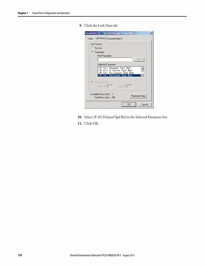
Chapter 1 Detail Drive Configuration and Operation
9. Click the Link Data tab.
10. Select (P 45) Delayed Spd Ref in the Selected Parameter list.
11. Click OK.
170 Rockwell Automation Publication PFLEX-RM002D-EN-E - August 2013

Detail Drive Configuration and Operation Chapter 1
Follower PowerFlex 700S Setup (Receiving Drive)
1. In the slave drive, select 4 Direct Words, 8 Buffered Words in the SynchLink Receive Format field, to match the size of the data transmitted from the master drive.
2. If desired, the multiply block can be used to change the scaling of one of the Direct Words coming from the master to the follower. For example, the multiply block might be used to enter a gear ratio for the speed reference.
3. Click .
Rockwell Automation Publication PFLEX-RM002D-EN-E - August 2013 171

Chapter 1 Detail Drive Configuration and Operation
The Parameter 1000 - SL Node Cnfg Properties dialog box opens.
4. Verify that only the Sync Now check box is checked (this is the factory default).
5. Click OK.
The SynchLink communication dialog box re-opens.
6. Click OK,
You must link the speed reference bypass of the follower to Word 0 of Direct Data coming over SynchLink.
7. Open the Properties dialog box for Parameter 37 [Spd Ref Bypass].
8. Click on the Link Data tab.
172 Rockwell Automation Publication PFLEX-RM002D-EN-E - August 2013

Detail Drive Configuration and Operation Chapter 1
9. Select (P 1055 SL Dir Real Rx0) in the Selected Parameters list.
10. Click OK.
Note that by linking to [Spd Ref Bypass] of the follower, the ramp and S-Curve of the follower were bypassed. This is because the reference is already ramped and S-Curved by the master. This way, both drives follow exactly the same ramp.
Cycle Power
You must power down all drives before SynchLink changes take effect.
1. Remove power from all drives.
2. Apply power to the Master.
The SynchLink LED should be solid green. The SynchLink LED is on the top right of the MCB and is visible through the window on the control assembly.
3. Apply power to the follower(s).
The SynchLink LED on the follower should be a solid light after about 1 minute.
Rockwell Automation Publication PFLEX-RM002D-EN-E - August 2013 173

Chapter 1 Detail Drive Configuration and Operation
Sync Generator The sync generator can be used to synchronize a parameter and delay it one scan. This can be used in conjunction with SynchLink (Refer to SynchLink on page 160 for more information).
Configuration:• Parameters 788 [Xsync In 1] and 789 [Xsync Out 1] can be used to
synchronize a Dint parameter.• Parameters 790 [Xsync In2] through 792 [Xsynch Out 2 Dly] can be used
to synchronize a Dint parameter and delay it one scan.• Parameters 793 [Xsync In3] through 795 [Xsynch Out 3 Dly] can be used
to synchronize a floating point parameter and delay it one scan.• Parameter 787 [Xsync Gen Period] sets the scan time of the synch
generator. The following options are available:
The default setting is 1 = “4 msec”.
Test Points Test points are used to monitor values in the drive for diagnostic information.
• [xxxx TP Sel] selects a value to monitor for diagnostics.
• [xxxx TP Data] shows the value selected by [xxxx TP Sel].
0 = 2 msec 3 = 16 msec
1 = 4 msec 4 = 32 msec
2 = 8 msec
Latch
Latch
Latch788
790
793
Sync Generator
787
789
791
792
794
795
317
0.5ms
Xsync In 1 Xsync Out 1
Xsync Out 2
Xsync In 2
Xsync In 3
Xsync Out 2 Dly
Xsync Out 3 Dly
Xsync Out 3
SL System Time
Sync Pulse Generator0.5ms * 2(p787)
0.5ms
786 00
Delay
OneScan
Delay
OneScan
Xsync Gen Period
Xsync Status(Sync Pulse)
174 Rockwell Automation Publication PFLEX-RM002D-EN-E - August 2013

Detail Drive Configuration and Operation Chapter 1
Thermal Regulator See Drive Overload on page 48.
Torque Reference When the PowerFlex 700S is operated in Torque mode, an external signal is used for a Torque reference. Refer to Figure 38 - for the firmware diagram.
Figure 38 - Torque Reference Firmware Diagram
Torque Reference Input
Parameter 111 [Torque Ref 1] is used to supply an external reference for desired torque. The scaling of this parameter is a per unit type, where a value of 1.0 is equal to the rated motor torque. The range is from -2200000000 to +2200000000.
[Torque Ref 1] is then divided by parameter 112 [Torq Ref1 Div]. This defines the scaled [Torque Ref 1].
Parameter 113 [Torque Ref 2] is used to supply an external reference for desired torque. The scaling of this parameter is a per unit type, where a value of 1.0 is equal to the rated motor torque. The range is from -2200000000 to +2200000000.
[Torque Ref 2] is then multiplied by parameter 114 [Torq Ref2 Mult]. This defines the scaled [Torque Ref 2].
The torque reference can be utilized when a master/slave multi-drive system is configured. The torque reference into the “slave” can be scaled to create the proper torque output. Keep in mind that the motors may be different ratings and this function is used to help the “system” share the load.
Parameter 115 [Torque Trim] can be used to trim the torque.For example, [Torque Trim] can be limited to an analog input or to the Process PI output.
Once the scaling is complete on both [Torque Ref 1] and [Torque Ref 2], the output is summed with the output of the [Torque Trim].
111
X
112
113
114
115
/
++
+
Torque Ref 1
Torque Ref1 Div
Torque Ref 2
Torque Ref2 Mult
Torque Trim
Rockwell Automation Publication PFLEX-RM002D-EN-E - August 2013 175

Chapter 1 Detail Drive Configuration and Operation
Unbalanced or Ungrounded Distribution Systems
Unbalanced Distribution Systems
This drive is designed to operate on three-phase supply systems whose line voltages are symmetrical. Surge suppression devices are included to protect the drive from lightning induced overvoltages between line and ground. Where the potential exists for abnormally high phase-to-ground voltages (in excess of 125% of nominal), or where the supply ground is tied to another system or equipment that could cause the ground potential to vary with operation, suitable isolation is required for the drive. Where this potential exists, an isolation transformer is strongly recommended.
Ungrounded Distribution Systems
All drives are equipped with an MOV (Metal Oxide Varistor) that provides voltage surge protection and phase-to-phase plus phase-to-ground protection which is designed to meet IEEE 587. The MOV circuit is designed for surge suppression only (transient line protection), not continuous operation.
With ungrounded distribution systems, the phase-to-ground MOV connection could become a continuous current path to ground. Energy ratings are listed below. Exceeding the published phase-to-phase or phase-to-ground energy ratings may cause physical damage to the MOV.
PowerFlex drives contain protective MOVs and common mode capacitors that are referenced to ground. To guard against drive damage, these devices should be disconnected if the drive is installed on an ungrounded distribution system where the line-to-ground voltages on any phase could exceed 125% of the nominal line-to-line voltage. Refer to your PowerFlex User Manual, 20D-UM001, for details.
1 2 3 4
Joules (J)Ground
Three-PhaseAC Input
T
SR
Joules (J)
Joules (J)
Joules (J)
Device Rating (V AC)Phase-Phase TotalPhase-Ground Total
240/480 600280J 320J360J 410J
240 480/600160J 320J220J 380J
240/480 600280J 300J360J 370J
Phase-to-Phase MOV RatingIncludes 2 Phase-Phase MOVs
Phase-to-Ground MOV RatingIncludes Phase-Phase & Phase-Ground MOVs
176 Rockwell Automation Publication PFLEX-RM002D-EN-E - August 2013
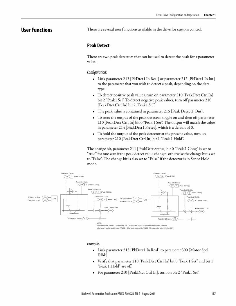
Detail Drive Configuration and Operation Chapter 1
User Functions There are several user functions available in the drive for custom control.
Peak Detect
There are two peak detectors that can be used to detect the peak for a parameter value.
Configuration:• Link parameter 213 [PkDtct1 In Real] or parameter 212 [PkDtct1 In Int]
to the parameter that you wish to detect a peak, depending on the data type.
• To detect positive peak values, turn on parameter 210 [PeakDtct Ctrl In] bit 2 “Peak1 Sel”. To detect negative peak values, turn off parameter 210 [PeakDtct Ctrl In] bit 2 “Peak1 Sel”.
• The peak value is contained in parameter 215 [Peak Detect1 Out].• To reset the output of the peak detector, toggle on and then off parameter
210 [PeakDtct Ctrl In] bit 0 “Peak 1 Set”. The output will match the value in parameter 214 [PeakDtct1 Preset], which is a default of 0.
• To hold the output of the peak detector at the present value, turn on parameter 210 [PeakDtct Ctrl In] bit 1 “Peak 1 Hold”.
The change bit, parameter 211 [PeakDtct Status] bit 0 “Peak 1 Chng” is set to “true” for one scan if the peak detect value changes, otherwise the change bit is set to “False”. The change bit is also set to “False” if the detector is in Set or Hold mode.
Example:• Link parameter 213 [PkDtct1 In Real] to parameter 300 [Motor Spd
Fdbk].• Verify that parameter 210 [PeakDtct Ctrl In] bit 0 “Peak 1 Set” and bit 1
“Peak 1 Hold” are off.• For parameter 210 [PeakDtct Ctrl In], turn on bit 2 “Peak1 Sel”.
214
212
213
210 2
0211
1210
0210
215
Peak Ctrl Status
(Peak 1 Chng)
PkDtct1 In Real
PeakDtct1 In Int
PeakDtct1 Ctrl In
(Peak 1 Sel)
PeakDtct1 Preset
Peak Detect1 Out
(Peak 1 Set)
PeakDtct1 Ctrl In
(Peak 1 Hold)
218
210 6
1211
5210
4210
219
OR216
217
Peak Ctrl Status
(Peak 2 Chng)
PkDtct2 In Real
PeakDtct2 In Int
PeakDtct Ctrl In(Peak 2 Sel)
PeakDtct2 Preset
Peak Detect2 Out
(Peak 2 Set)
PeakDtct2 Ctrl In(Peak 2 Hold)
OR
InvInv
PeakDtct2 Ctrl InPeakDtct1 Ctrl In
The change bit , Peak x Chng (where x = 1 or 2), is set TRUE if the peak detect value changes, otherwise the change bit is set FALSE . Change is also set to FALSE if the detector is in HOLD or SET.
NOTE:
Rockwell Automation Publication PFLEX-RM002D-EN-E - August 2013 177

Chapter 1 Detail Drive Configuration and Operation
• Parameter 215 [Peak Detect1 Out] will contain the positive peak value of [Motor Spd Fdbk].
• To reset the output of the peak detector, parameter 210 [PeakDtct Ctrl In] toggle on and then off bit 0 “Peak 1 Set”.
Selector Switches
There are two different selector switches available:
• A switch that selects between two Dint values. The result is Dint.
• A switch that selects between two floating-point values. The result is floating point.
Two Position Dint Switch
Configuration:• Parameter 1370 [Switch Control] bit 1 “SW Int 1 On” activates the
switch.• The value of parameter 1371 [SW Int 1 NO] is moved into parameter
1373 [SW Int 1 Output] when bit 1 “SW Int 1 On” of parameter 1370 [Switch Control] is on.
• The value of parameter 1372 [SW Int 1 NC] is moved into parameter 1373 [SW Int 1 Output] when bit 1 “SW Int 1 On” of parameter 1370 [Switch Control] is off.
• [SW Int 1 Output] contains the value of either [SW Int 1 NO] or [SW Int 1 NC].
1371
1372
1370 1
1
0 1373
Switch Control(SW Int 1 On)
SW Int 1 NO
SW Int 1 NC SW Int 1 Output
178 Rockwell Automation Publication PFLEX-RM002D-EN-E - August 2013
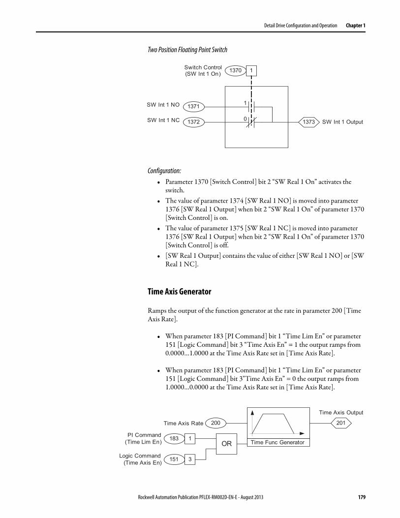
Detail Drive Configuration and Operation Chapter 1
Two Position Floating Point Switch
Configuration:• Parameter 1370 [Switch Control] bit 2 “SW Real 1 On” activates the
switch.• The value of parameter 1374 [SW Real 1 NO] is moved into parameter
1376 [SW Real 1 Output] when bit 2 “SW Real 1 On” of parameter 1370 [Switch Control] is on.
• The value of parameter 1375 [SW Real 1 NC] is moved into parameter 1376 [SW Real 1 Output] when bit 2 “SW Real 1 On” of parameter 1370 [Switch Control] is off.
• [SW Real 1 Output] contains the value of either [SW Real 1 NO] or [SW Real 1 NC].
Time Axis Generator
Ramps the output of the function generator at the rate in parameter 200 [Time Axis Rate].
• When parameter 183 [PI Command] bit 1 “Time Lim En” or parameter 151 [Logic Command] bit 3 “Time Axis En” = 1 the output ramps from 0.0000…1.0000 at the Time Axis Rate set in [Time Axis Rate].
• When parameter 183 [PI Command] bit 1 “Time Lim En” or parameter 151 [Logic Command] bit 3"Time Axis En” = 0 the output ramps from 1.0000…0.0000 at the Time Axis Rate set in [Time Axis Rate].
1371
1372
1370 1
1
0 1373
Switch Control(SW Int 1 On)
SW Int 1 NO
SW Int 1 NC SW Int 1 Output
OR
200 201
Time Func GeneratorPI Command
(Time Lim En)
Logic Command(Time Axis En)
Time Axis Rate
Time Axis Output
183 1
151 3
Rockwell Automation Publication PFLEX-RM002D-EN-E - August 2013 179

Chapter 1 Detail Drive Configuration and Operation
Limit Generator
The limit generator generates a high and low limit based on an input.• The input parameter 206 [LimGen X axis In] is a linkable destination for
floating point parameters. The input range is 0.0000…1.0000.• The output is equal to parameter 205 [LimGen Y axis Mn] when the input
is equal to 0.0000.• The output is equal to parameter 204 [LimGen Y axis Mx] when the input
is equal to 1.0000.• The output is available as a positive output parameter 207 [Limit Gen Hi
Out] and a negative output parameter 208 [Limit Gen Lo Out].
Voltage Class PowerFlex drives are sometimes referred to by voltage “class.” This class identifies the general input voltage to the drive. This general voltage includes a range of actual voltages. For example, a 400 Volt Class drive will have an input voltage range of 380…480VAC. While the hardware remains the same for each class, other variables, such as factory defaults, catalog number and power unit ratings will change. In most cases, all drives within a voltage class can be reprogrammed to another drive in the class by resetting the defaults to something other than “factory” settings. Parameter 403 [Voltage Class] can be used to reset a drive to a different setup within the voltage class range.
As an example, consider a 480V drive. This drive comes with factory default values for 480V, 60 Hz with motor data defaulted for U.S. motors (HP rated, 1750 rpm, etc.) By setting the [Voltage Class] parameter to “Low Voltage” (this represents 400V in this case) the defaults are changed to 400V, 50 Hz settings with motor data for European motors (kW rated, 1500 rpm, etc.).
205
204
206
207
208Limit Generator
-1 +1
-1LimGen X axis In
LimGen Y axis Mx
LimGen Y axis Mn
Limit Gen Hi Out
Limit Gen Lo Out
180 Rockwell Automation Publication PFLEX-RM002D-EN-E - August 2013

Detail Drive Configuration and Operation Chapter 1
Watts Loss The following table lists watts loss data for PowerFlex 700S drives running at full load, full speed, and factory default PWM frequency of 4 kHz.
Table 13 - 480V Watts Loss at Full Load/Speed, 4 kHz (1)
(1) Includes HIM(2) Information not available at time of publication
Drive ND HP @ 480V AC Total Watt Loss
0.5 92
1 103
2 117
3 135
5 210
7.5 243
10 271
15 389
20 467
25 519
30 543
40 708
50 (2)
60 (2)
75 (2)
100 (2)
125 (2)
150 (2)
Rockwell Automation Publication PFLEX-RM002D-EN-E - August 2013 181

Chapter 1 Detail Drive Configuration and Operation
Notes:
182 Rockwell Automation Publication PFLEX-RM002D-EN-E - August 2013

Appendix A
History of Changes
This appendix summarizes the revisions to this manual. Reference this appendix if you need information to determine what changes have been made across multiple revisions. This may be especially useful if you are deciding to upgrade your hardware or firmware based on information added with previous revisions of this manual.
PFLEX-RM002C-EN-ETopic
Updated specifications and dimensions
“Alarms” section updated
Added “Copy Cat” section
“Digital Inputs” section updated
“Direction Control and Bipolar Reference” section updated
Added “Drive Overload Temperature (Frame 9 Only)” section
Updated the Efficiency” section
Updated the “Faults” section
New “Flying Start” section
Updated drive ratings tables in the “Fuses and Circuit Brakers” section
Updated the “HIM Operations” section
Added compatible PMM tables to the “Permanent Magnet Motors” section
Updated the “Position Loop - Follower (Electronic Gearing)” section
Added the “Position Loop - In Position Detect” section
Updated the “Position Loop - Point to Point” section
Added the “Position Loop - Registration” section
Updated the “Power Loss/Ride Through” section
Added the “Reflected Wave” section
Updated the “Speed/Position Feedback” section
Updated the “Speed PI Regulator” section
Updated the “Speed/Torque Selection” section
Updated the “User Functions” section
Rockwell Automation Publication PFLEX-RM002D-EN-E - August 2013 183

Appendix A History of Changes
Notes:
184 Rockwell Automation Publication PFLEX-RM002D-EN-E - August 2013

Index
Numerics20-COMM-C 2620-COMM-D 3620-COMM-R 106
AAccel Time 13Al x Filt Gain 14Alarms 13Analog Input Configuration 14Analog Inputs 14Anlg Inx Data 14Anlg Inx Filt BW 14Anlg Inx Offset 14Anlg Inx Scale 14Anlg Inx Volts 14Anlg Out Real 16Anlg Outx Integer 16Anlg Outx Scale 16Anlg Outx Zero 16Applied LogicCmd 149Atune Spd Ref 20Atune Torq Ref 20Auto Restart 17Auto/Manual 17Autotune
Direction Test 19Feedback Configuration 18Inertia Test 20Motor Control 18Motor Data 18Motor Tests 19Power Circuit Test 18Start-Up Menu 17Troubleshooting 20
Auxiliary Power Supply 20
BBasic tuning with a gearbox or belt 127Bus Regulation 20
CCable Trays and Conduit 24Cable, Control 24Cable, Motor Lengths 24Cable, Power 24Carrier (PWM) Frequency 25CE
Conformity 26Common Bus Systems 26Communication 26Conduit
Cable Trays 24
Control Options 47, 149, 151ControlNet 26
ControlLogix Programming 31Datalinks Programming 32Explicit Messaging 32Setup Information 26Technical Information 28
Copy Cat 33Current Limit 33
DDatalinks
Configuration 34Decel Time 36DeltaSpeedScale 68DeviceNet 36DigIn 1 Sel 43DigIn 2 Sel 44DigIn 3 Sel 44DigIn x Data 44DigIn x Debounce 44DigIn x User Data 44Digital Inputs 42Digital Outputs 46Direction Control
Bipolar Reference 47Distribution Systems 176, 177
Unbalanced 176Ungrounded 176
DPI 50Drive OL JnctTmp 50Drive OL Status 49Drive Overload 48DriveLogix 52Dynamic Braking 53
EEfficiency 53Electronic Gearing 53Encdr x Config 139Encdr1 Position 93Encoder x PPR 138Exception Event1 150, 151
FFaults 54Fdbk LsCnfg Alt 150Fdbk LsCnfg Pri 150Field Oriented Control 19Filters 54Friction Compensation 64Functions 177FVC Mode Config 150
Rockwell Automation Publication PFLEX-RM002D-EN-E - August 2013 185

Index
FW Functions En 93
GGrounding, General 66
HHeatsink Temp 50HIM
Memory 66Operations 66
HS OverTemp 49HS Pending 49Human Interface Module
User Display 66
IInertia Adaptation 67Inertia Compensation 68Inertia Torq Add 68InertiaAccelGain 68Input Devices 69Input Modes 69Input Power Conditioning 69IT Foldback 49IT Pending 49IT Trip 49
JJnc Over Temp 49Jog 69
LLead-Lag Filter 56Links 70Logic Command 68, 92, 149, 151Low Pass Filter 55
MMasks 72Motor Control Mode 72Motor Fdbk Sel 137Motor Nameplate 73Motor Overload 73Motor Start/Stop 75Mounting 75Mounting Dimensions 75Mtr Fdbk Alt Sel 137Mtr Fdbk Sel Alt 149, 150, 151Mtr Fdbk Sel Pri 149, 150, 151
NNotch Filter 59NTC Open 49NTC Shorted 49
OOutput Devices
Drive Output Disconnection 76Output Reactor 76
Output DisplayCurrent 76Frequency 76Power 77Voltage 77
Overcurrent 33Overspeed Limit 77Owners 77
PParameter Access Level 79Parameters
Accel Time 13Anlg In1 Data 15Anlg In1 Offset 15Anlg In1 Scale 15Anlg In1 Volts 15Anlg ln1 Data 15Anlg ln1 Filt Gain 15Anlg ln1 Offset 15Anlg ln1 Scale 15Anlg ln1Filt BW 15Anlg Out1 Integer 17Applied LogicCmd 149Brake PulseWatts 22Brake TP Data 24Brake TP Sel 24Bus Reg/Brake Ref 21Bus/Brake Cnfg 21Control Options 149, 151Data In A1 Int 34Data In A1 Real 35Data Out A1 Int 35Decel Time 36Delayed Spd Ref 170Dig Out 1 Bit 47Dig Out 1 Data 47DigIn 1 Bit 45DigIn 1 Data 45DigIn 1 Sel 45DigIn 1 User Data 45Direction Mask 72Direction Owner 77Dlink OutDataTyp 111Dlink OutDataType 30, 35DPI Ref Select 31, 38Drive Logic Rslt 28, 36Encdr1 Position 93Exception Event1 150, 151Fault Clr Owner 77Fdbk LsCnfg Alt 150Fdbk LsCnfg Pri 150
186 Rockwell Automation Publication PFLEX-RM002D-EN-E - August 2013

Index
Parameters, ContinuedFVC Mode Config 150FW Functions En 93Jog Owner 77Local I/O Status 45Logic Command 92, 149, 151Logic Status 28, 47MC Diag Error 1 20MC Diag Error 2 20MC Diag Error 3 20Motor Ctrl Mode 18Motor NP FLA 73Motor NP Hz 73Motor NP Power 73Motor NP Pwr Units 73Motor NP RPM 13, 36, 73Motor NP Volts 73Motor Poles 73Mtr Fdbk Sel Alt 149, 150, 151Mtr Fdbk Sel Pri 149, 150, 151Mtr TrqCurr Ref 17Output Curr Disp 76Output Current 35Posit Detct1 In 92, 93PositDetct1 Stpt 93Position Actual 92Position Control 34, 93Position Error 17Position Status 35, 93Rated Volts 22Real to Int In 162Real to Int Out 162S Curve Spd Ref 162, 168SL Dir Int Rx0 161SL Dir Int Rx3 161SL Dir Int Tx0 161, 162SL Dir Int Tx3 161SL Dir Real Rx0 161, 173SL Dir Real Rx3 161SL Dir Real Tx0 161SL Dir Real Tx3 161SL Mult A In 163SL Mult B In 163SL Mult Base 162SL Mult Out 163SL Mult State 162, 163SL Node Cnfg 160SL Rx Comm Frmt 160SL Rx DirectSel0 161SL Rx DirectSel3 161SL Tx DirectSel0 161SL Tx DirectSel3 161Spd Fdbk Scale 29Spd Ref 1 15Spd Ref Bypass 169, 172Speed Ref 2 32, 38Speed Ref Sel 31, 38Start Owner 77Stop Owner 77TachSwitch Level 150, 151Torque Ref 1 35Tx Buf Data Type 163Tx Dir Data Type 161
Permanent Magnet Control 19Permanent Magnet Motors 79PI Loop 102
Posit Detct1 In 92, 93PositDetct1 Stpt 93Position Actual 92Position Control 93Position Loop
Follower (Electronic Gearing) 82In Position Detect 87Point to Point 87Registration 94
Position Loop - Position Watch 92Position Status 93Power Loss 95Preset Speeds 102Process PI Loop 102
Process PI Limits 103Process PI Output 104Process PI Reference and Feedback 103Process PI Regulator 103
pulse elimination technique (PET) 104PWM Frequency 25
RReflected Wave 104Remote I/O Adapter
ControlLogix System 106Datalink Programming 111Reference/Feedback Programming 110
RFI Filter Grounding 119Ride Through 95
SS Curve Spd Ref 68S-Curve 119Second Order Low Pass Filter 55Speed Comp 69Speed Control 119Speed Feedback 137Speed Mode 119Speed PI Regulator 120
Autotune Speed Reference 121Current Limit Stop 122Droop 126Integral Gain 124Proportional Gain 124Servo Lock 123Speed Error 122Speed Reference Limits 122Speed Regulation Anti-Backup 123Speed Regulator Output Filter 126Speed Regulator Output Limits 126Speed Trim 120
Speed Ref Sel 45
Rockwell Automation Publication PFLEX-RM002D-EN-E - August 2013 187

Index
Speed Reference 130Accel/Decel Ramp and S-Curve 134Direction Control and Bipolar Reference 133Friction Compensation 135Inertia Compensation 135Jog Reference 133Speed Limits 133Speed Reference Bypass and Delayed Speed
Reference 135Speed Reference Filter 136Speed Reference Scale 136Speed Reference Scaling 131Speed Reference Select 132Speed Trim1 137Stop Command 133Virtual Encoder 135
Speed Reference Select 137Speed Regulation 119Speed Trim 3 69Speed/Position Feedback
Encoder 137Feedback Device 137Feedback Option Cards 143Motor Position Feedback 147Motor Simulator 142Motor Speed Feedback and Scaled Speed
Feedback 148Sensorless 142
SpeedTrim3 Scale 69Start Inhibits 155Start/Stop Modes
Configuring the Start and Stop for 2-Wire Control 158
Configuring the Start and Stop for 3-Wire Control 157
Start-Up 160Stop Modes 160sync generator 174SynchLink
Buffered Data 163Configuration 160Direct Data 161Master PowerFlex 700S Setup 168Multiply Block 162Slave PowerFlex 700S Setup 171Speed Synchronization Example 167Technical Information 160
TTachSwitch Level 150, 151Test Points 174Thermal Regulator 175Torque Reference 175Torque Select 152Total Inertia 20
UUnbalanced
Distribution Systems 176, 177
UngroundedDistribution Systems 176, 177
Ungrounded Distribution Systems 176User Display, HIM 66User Functions 177
VVoltage Class 180
WWatts Loss 181
188 Rockwell Automation Publication PFLEX-RM002D-EN-E - August 2013


Publication PFLEX-RM002D-EN-E - August 2013 Supersedes Publication PFLEX-RM002C-EN-E - September 2005 Copyright © 2013 Rockwell Automation, Inc. All rights reserved. Printed in the U.S.A.
Rockwell Automation Support
Rockwell Automation provides technical information on the Web to assist you in using its products.At http://www.rockwellautomation.com/support you can find technical and application notes, sample code, and links to software service packs. You can also visit our Support Center at https://rockwellautomation.custhelp.com/ for software updates, support chats and forums, technical information, FAQs, and to sign up for product notification updates.
In addition, we offer multiple support programs for installation, configuration, and troubleshooting. For more information, contact your local distributor or Rockwell Automation representative, or visithttp://www.rockwellautomation.com/services/online-phone.
Installation Assistance
If you experience a problem within the first 24 hours of installation, review the information that is contained in this manual. You can contact Customer Support for initial help in getting your product up and running.
New Product Satisfaction Return
Rockwell Automation tests all of its products to help ensure that they are fully operational when shipped from the manufacturing facility. However, if your product is not functioning and needs to be returned, follow these procedures.
Documentation Feedback
Your comments will help us serve your documentation needs better. If you have any suggestions on how to improve this document, complete this form, publication RA-DU002, available at http://www.rockwellautomation.com/literature/.
United States or Canada 1.440.646.3434
Outside United States or Canada Use the Worldwide Locator at http://www.rockwellautomation.com/rockwellautomation/support/overview.page, or contact your local Rockwell Automation representative.
United States Contact your distributor. You must provide a Customer Support case number (call the phone number above to obtain one) to your distributor to complete the return process.
Outside United States Please contact your local Rockwell Automation representative for the return procedure.
Rockwell Otomasyon Ticaret A.Ş., Kar Plaza İş Merkezi E Blok Kat:6 34752 İçerenköy, İstanbul, Tel: +90 (216) 5698400