Embed Size (px)
Citation preview

1 | P a g e
2011
Avinash.E
ERL INDIA
Power Transformer Connections, Determination of “Transformer Connections” &
their “Analog Phase Shift”

Introduction Power transformer is one of the most important links in a power system. Its development stems from the early days of electromagnetic induction, when it was discovered that varying magnetic flux in an iron core linking two coils produces an induced voltage. From the basic discovery has evolved the power transformer we know today using advanced insulation materials and having complex windings on a laminated core using special magnetic steels cold rolled to ensure grain orientation for low loss and high operating density. Depending on the method chosen for the primary and the secondary, a phase-shift can take place between the corresponding phases in the primary and secondary voltages of a transformer. Clock face numbers are used to represent phase shifts, the highest voltage winding being used as the reference. A 360° shift corresponds to a full 12 h of a clock with each 30° shift being represented by 1 h. For example, 30° corresponds to 1 o’clock position, 150° shift corresponds to 5 o’clock position and 330 (or –30)° shift corresponds to 11 o’clock position. The vector grouping and phase shift can then be expressed using a simple code. The primary winding connection is represented by capital letter while small letter represents the secondary connection. The ‘N’ means the primary neutral has been brought out. For example: YNd1= Primary winding connected in star with neutral brought out. Secondary winding connected in delta. Phase shift of secondary 30° from 12 to 1 o’clock compared to primary phase angle. With the development of poly phase systems with more complex transformer winding connections and also possible phase displacement between primary and secondary windings, standardisation was necessary to ensure universal compatibility, There are a number of possible transformer connections but the more common connections are divided into four main groups. Group 1: 00 Phase displacement Group 2: 1800 Phase displacement E.g: Yy0 E.g: Yy6 Dd0 Dd6 Group 3: 300 Phase displacement Group 4: 3300 Phase displacement E.g: Yd1 E.g: Yd11 Dy1 Dy11
Determination of Transformer Connections
The Connections of a transformer mainly depends on the phase shift that is to be obtained. The connections of the transformer for different possible combinations are explained as follows: The following points should be noted:
A. The line connections are normally made to the end of the winding which carries the subscript 2 i.e. A 2, B2, C2 and a2, b2, c2.
B. The line terminal designation (both letter and subscript) are the same as those of the phase winding to which the line terminal is connected.
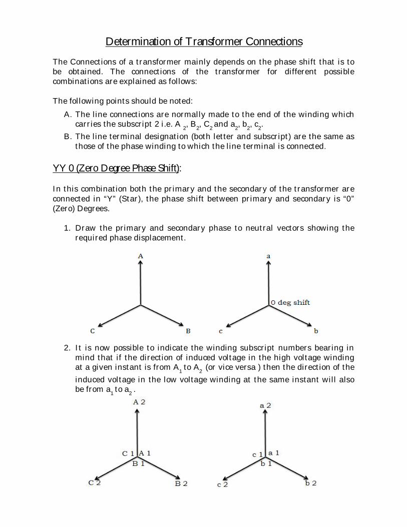
YY 0 (Zero Degree Phase Shift): In this combination both the primary and the secondary of the transformer are connected in “Y” (Star), the phase shift between primary and secondary is “0” (Zero) Degrees.
1. Draw the primary and secondary phase to neutral vectors showing the required phase displacement.
2. It is now possible to indicate the winding subscript numbers bearing in mind that if the direction of induced voltage in the high voltage winding at a given instant is from A1 to A2 (or vice versa ) then the direction of the induced voltage in the low voltage winding at the same instant will also be from a1 to a2 .
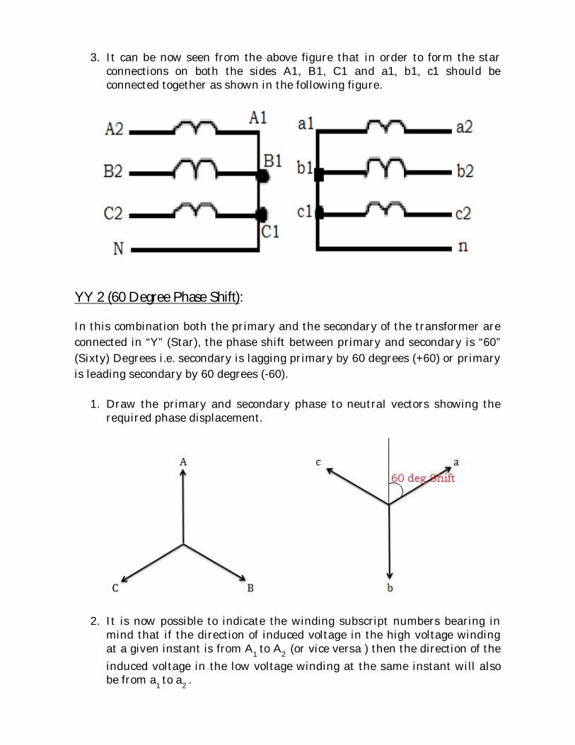
3. It can be now seen from the above figure that in order to form the star connections on both the sides A1, B1, C1 and a1, b1, c1 should be connected together as shown in the following figure.
YY 2 (60 Degree Phase Shift): In this combination both the primary and the secondary of the transformer are connected in “Y” (Star), the phase shift between primary and secondary is “60” (Sixty) Degrees i.e. secondary is lagging primary by 60 degrees (+60) or primary is leading secondary by 60 degrees (-60).
1. Draw the primary and secondary phase to neutral vectors showing the required phase displacement.
2. It is now possible to indicate the winding subscript numbers bearing in mind that if the direction of induced voltage in the high voltage winding at a given instant is from A1 to A2 (or vice versa ) then the direction of the induced voltage in the low voltage winding at the same instant will also be from a1 to a2 .

3. It can be now seen from the above figure that “ a = -C, b = -A, c = -B”, in order to form the star connections on both the sides A1, B1, C1 and a2, b2, c2 should be connected together as shown in the following figure.
YY 4 (120 Degree Phase Shift): In this combination both the primary and the secondary of the transformer are connected in “Y” (Star), the phase shift between primary and secondary is “120” Degrees i.e. secondary is lagging primary by 120 degrees (+120) or primary is leading secondary by 120 degrees (-120).
1. Draw the primary and secondary phase to neutral vectors showing the required phase displacement.

2. It is now possible to indicate the winding subscript numbers bearing in mind that if the direction of induced voltage in the high voltage winding at a given instant is from A1 to A2 (or vice versa ) then the direction of the induced voltage in the low voltage winding at the same instant will also be from a1 to a2 .
3. It can be now seen from the above figure that “ a = B, b = C, c = A”, in order to form the star connections on both the sides A1, B1, C1 and a1, b1, c1 should be connected together as shown in the following figure.
YY 6 (180 Degree Phase Shift): In this combination both the primary and the secondary of the transformer are connected in “Y” (Star), the phase shift between primary and secondary is “180” Degrees i.e. secondary is lagging primary by 180 degrees (+180) or primary is leading secondary by 180 degrees (-180).
1. Draw the primary and secondary phase to neutral vectors showing the required phase displacement.

2. It is now possible to indicate the winding subscript numbers bearing in mind that if the direction of induced voltage in the high voltage winding at a given instant is from A1 to A2 (or vice versa ) then the direction of the induced voltage in the low voltage winding at the same instant will also be from a1 to a2 .
3. It can be now seen from the above figure that “ a = -A, b = -B, c = -C”, in
order to form the star connections on both the sides A1, B1, C1 and a2, b2, c2 should be connected together as shown in the following figure.

YY 8 (240 or 120 Degree Phase Shift): In this combination both the primary and the secondary of the transformer are connected in “Y” (Star), the phase shift between primary and secondary is “240” Degrees i.e. secondary is lagging primary by 240 degrees (+240) or primary is lagging secondary by 120 degrees (+120).
1. Draw the primary and secondary phase to neutral vectors showing the required phase displacement.
2. It is now possible to indicate the winding subscript numbers bearing in mind that if the direction of induced voltage in the high voltage winding at a given instant is from A1 to A2 (or vice versa ) then the direction of the induced voltage in the low voltage winding at the same instant will also be from a1 to a2 .
3. It can be now seen from the above figure that “ a = C, b = A, c = B”, in order to form the star connections on both the sides A1, B1, C1 and a1, b1, c1 should be connected together as shown in the following figure.
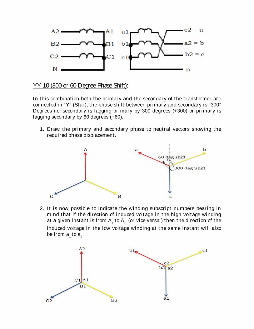
YY 10 (300 or 60 Degree Phase Shift): In this combination both the primary and the secondary of the transformer are connected in “Y” (Star), the phase shift between primary and secondary is “300” Degrees i.e. secondary is lagging primary by 300 degrees (+300) or primary is lagging secondary by 60 degrees (+60).
1. Draw the primary and secondary phase to neutral vectors showing the required phase displacement.
2. It is now possible to indicate the winding subscript numbers bearing in mind that if the direction of induced voltage in the high voltage winding at a given instant is from A1 to A2 (or vice versa ) then the direction of the induced voltage in the low voltage winding at the same instant will also be from a1 to a2 .
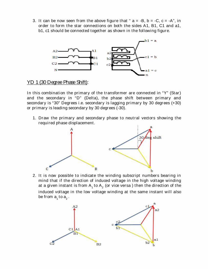
3. It can be now seen from the above figure that “ a = -B, b = -C, c = -A”, in order to form the star connections on both the sides A1, B1, C1 and a1, b1, c1 should be connected together as shown in the following figure.
YD 1 (30 Degree Phase Shift): In this combination the primary of the transformer are connected in “Y” (Star) and the secondary in “D” (Delta), the phase shift between primary and secondary is “30” Degrees i.e. secondary is lagging primary by 30 degrees (+30) or primary is leading secondary by 30 degrees (-30).
1. Draw the primary and secondary phase to neutral vectors showing the required phase displacement.
2. It is now possible to indicate the winding subscript numbers bearing in
mind that if the direction of induced voltage in the high voltage winding at a given instant is from A1 to A2 (or vice versa ) then the direction of the induced voltage in the low voltage winding at the same instant will also be from a1 to a2 .

3. It can be now seen from the above figure that by connecting “c1, a2 = a;
a1, b2 = b; b1, c2 = c” phase as shown in the following figure.
YD 3 (90 Degree Phase Shift): In this combination the primary of the transformer are connected in “Y” (Star) and the secondary in “D” (Delta), the phase shift between primary and secondary is “90” Degrees i.e. secondary is lagging primary by 90 degrees (+90) or primary is leading secondary by 90 degrees (-90).
1. Draw the primary and secondary phase to neutral vectors showing the required phase displacement.
2. It is now possible to indicate the winding subscript numbers bearing in
mind that if the direction of induced voltage in the high voltage winding at a given instant is from A1 to A2 (or vice versa ) then the direction of the induced voltage in the low voltage winding at the same instant will also be from a1 to a2 .
3. It can be now seen from the above figure that by connecting “c1, b2 = a; a1, c2 = b; b1, a2 = c” phase as shown in the following figure.
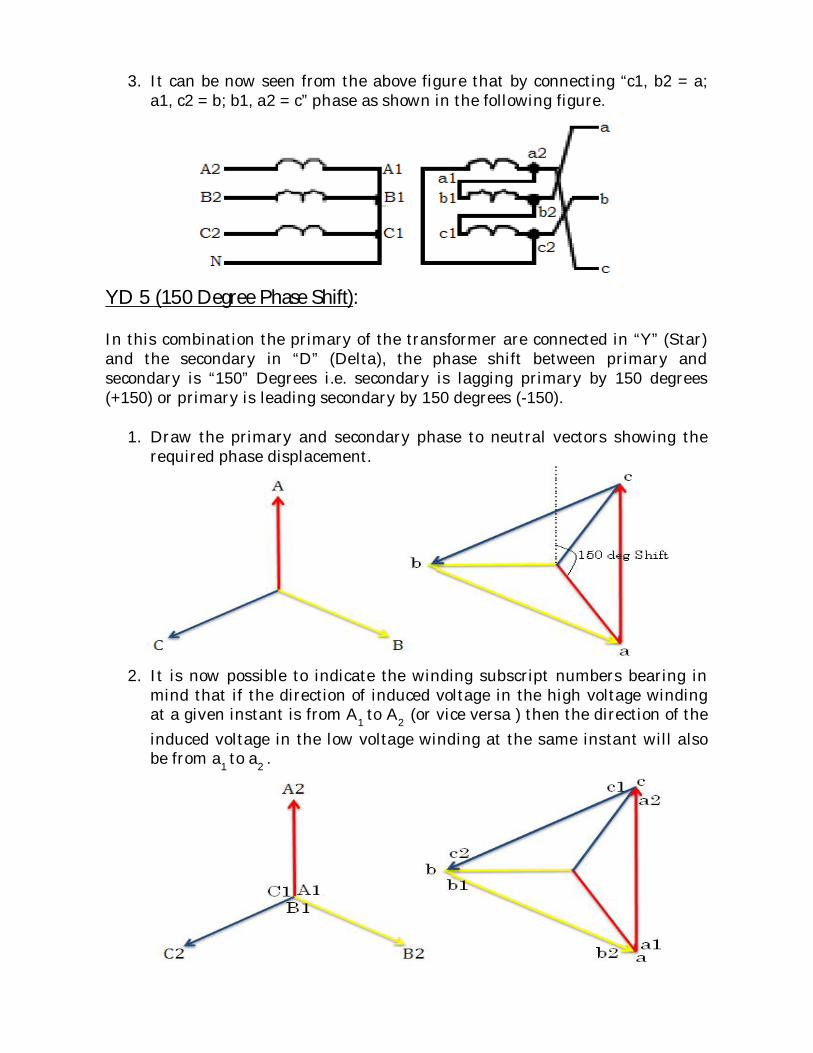
YD 5 (150 Degree Phase Shift): In this combination the primary of the transformer are connected in “Y” (Star) and the secondary in “D” (Delta), the phase shift between primary and secondary is “150” Degrees i.e. secondary is lagging primary by 150 degrees (+150) or primary is leading secondary by 150 degrees (-150).
1. Draw the primary and secondary phase to neutral vectors showing the required phase displacement.
2. It is now possible to indicate the winding subscript numbers bearing in
mind that if the direction of induced voltage in the high voltage winding at a given instant is from A1 to A2 (or vice versa ) then the direction of the induced voltage in the low voltage winding at the same instant will also be from a1 to a2 .
3. It can be now seen from the above figure that by connecting “a1, b2 = a; b1, c2 = b; c1, a2 = c” phase as shown in the following figure.
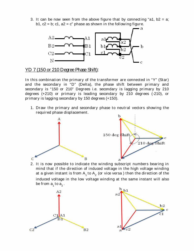
YD 7 (150 or 210 Degree Phase Shift): In this combination the primary of the transformer are connected in “Y” (Star) and the secondary in “D” (Delta), the phase shift between primary and secondary is “150 or 210” Degrees i.e. secondary is lagging primary by 210 degrees (+210) or primary is leading secondary by 210 degrees (-210), or primary is lagging secondary by 150 degrees (+150).
1. Draw the primary and secondary phase to neutral vectors showing the required phase displacement.
2. It is now possible to indicate the winding subscript numbers bearing in
mind that if the direction of induced voltage in the high voltage winding at a given instant is from A1 to A2 (or vice versa ) then the direction of the induced voltage in the low voltage winding at the same instant will also be from a1 to a2 .

3. It can be now seen from the above figure that by connecting “a1, c2 = a; b1, a2 = b; c1, b2 = c” phase as shown in the following figure.
YD 9 (270 or 90 Degree Phase Shift): In this combination the primary of the transformer are connected in “Y” (Star) and the secondary in “D” (Delta), the phase shift between primary and secondary is “90 or 270” Degrees i.e. secondary is lagging primary by 270 degrees (+270) or primary is leading secondary by 270 degrees (-270), or primary is lagging secondary by 90 degrees (+90).
1. Draw the primary and secondary phase to neutral vectors showing the required phase displacement.
2. It is now possible to indicate the winding subscript numbers bearing in
mind that if the direction of induced voltage in the high voltage winding at a given instant is from A1 to A2 (or vice versa ) then the direction of the induced voltage in the low voltage winding at the same instant will also be from a1 to a2 .

3. It can be now seen from the above figure that by connecting “b1, c2 = a; c1, a2 = b; a1, b2 = c” phase as shown in the following figure.
YD 11 (330 or 30 Degree Phase Shift): In this combination the primary of the transformer are connected in “Y” (Star) and the secondary in “D” (Delta), the phase shift between primary and secondary is “30 or 330” Degrees i.e. secondary is lagging primary by 330 degrees (+330) or primary is leading secondary by 330 degrees (-330), or primary is lagging secondary by 30 degrees (+30).
1. Draw the primary and secondary phase to neutral vectors showing the required phase displacement.
2. It is now possible to indicate the winding subscript numbers bearing in mind that if the direction of induced voltage in the high voltage winding at a given instant is from A1 to A2 (or vice versa ) then the direction of the induced voltage in the low voltage winding at the same instant will also be from a1 to a2 .

3. It can be now seen from the above figure that by connecting “b1, c2 = a; c1, a2 = b; a1, b2 = c” phase as shown in the following figure.

Determination of Analog phase Shift with “Zero Sequence Correction” For deriving the equations of "Analog Phase Shift" with "Zero Sequence Correction" for different transformer configurations we have to see how the respective primary phase is connected in the secondary. Analog Phase Shift of YY0: In the case of "YY0" configuration, the phase shift is Zero degrees (0) and hence "A = a, B = b, C = c" which is represented in the following figure. Therefore the equations are as follows: IA = (Ia - I0) {where I0 = (Ia + Ib + Ic)/ 3} IA = Ia - (Ia + Ib + Ic) / 3 IA = (2Ia - Ib – Ic) / 3 Similarly IB = (Ib - I0) {where I0 = (Ia + Ib + Ic)/ 3} IB = Ib - (Ia + Ib + Ic) / 3 IB = (2Ib - Ia – Ic) / 3 And IC = (Ic - I0) {where I0 = (Ia - Ib - Ic)/ 3} IC = Ic - (Ia + Ib + Ic) / 3 IC = (2Ic - Ia – Ib) / 3 Analog Phase Shift of YY2: In the case of "YY2" configuration, the phase shift is Sixty degrees (60) and hence "A = -b, B = -c, C = -a" which is represented in the following figure. Therefore the equations are as follows: IA = -(Ib - I0) {where I0 = (Ia + Ib + Ic)/ 3} IA = -(Ib - (Ia + Ib + Ic) / 3) IA = (Ia - 2Ib + Ic) / 3 Similarly IB = -(Ic - I0) {where I0 = (Ia + Ib + Ic)/ 3} IB = -(Ic - (Ia + Ib + Ic) / 3) IB = (Ia + Ib – 2Ic)/ 3 And IC = -(Ia - I0) {where I0 = (Ia - Ib - Ic)/ 3} IC = -(Ia - (Ia + Ib + Ic) / 3) IC = (Ib + Ic - 2Ia) / 3

Analog Phase Shift of YY4: In the case of "YY4" configuration, the phase shift is 120 degrees and hence "A = c, B = a, C = b" which is represented in the following figure. Therefore the equations are as follows: IA = (Ic - I0) {where I0 = (Ia + Ib + Ic)/ 3} IA = (Ic - (Ia + Ib + Ic) / 3) IA = (2Ic - Ia - Ib) / 3 Similarly IB = (Ia - I0) {where I0 = (Ia + Ib + Ic)/ 3} IB = (Ia - (Ia + Ib + Ic) / 3) IB = (2Ia - Ib - Ic) / 3 And IC = (Ib - I0) {where I0 = (Ia + Ib + Ic)/ 3} IC = (Ib - (Ia + Ib + Ic) / 3) IC = (2Ib - Ia - Ic) / 3 Analog Phase Shift of YY6: In the case of "YY6" configuration, the phase shift is 180 degrees and hence "A = -a, B = -b, C = -c" which is represented in the following figure. Therefore the equations are as follows: IA = -(Ia - I0) {where I0 = (Ia + Ib + Ic)/ 3} IA = -(Ia - (Ia + Ib + Ic) / 3) IA = (Ic - 2Ia + Ib ) / 3 Similarly IB = -(Ib - I0) {where I0 = (Ia + Ib + Ic)/ 3} IB = -(Ib - (Ia + Ib + Ic) / 3) IB = (Ia - 2Ib + Ic ) / 3 And IC = -(Ic - I0) {where I0 = (Ia + Ib + Ic)/ 3} IC = -(Ic - (Ia + Ib + Ic) / 3) IC = (Ia - 2Ic +Ib ) / 3

Analog Phase Shift of YY8: In the case of "YY8" configuration, the phase shift is 240 degrees and hence "A = b, B = c, C = a" which is represented in the following figure. Therefore the equations are as follows: IA = (Ib - I0) {where I0 = (Ia + Ib + Ic)/ 3} IA = (Ib - (Ia + Ib + Ic) / 3) IA = (2Ib - Ic - Ia ) / 3 Similarly IB = (Ic - I0) {where I0 = (Ia + Ib + Ic)/ 3} IB = (Ic - (Ia + Ib + Ic) / 3) IB = (2Ic - Ia - Ib ) / 3 And IC = (Ia - I0) {where I0 = (Ia + Ib + Ic)/ 3} IC = (Ia - (Ia + Ib + Ic) / 3) IC = (2Ia - Ib - Ic ) / 3 Analog Phase Shift of YY10: In the case of "YY10" configuration, the phase shift is 300 degrees and hence "A = b, B = c, C = a" which is represented in the following figure. Therefore the equations are as follows: IA = (Ib - I0) {where I0 = (Ia + Ib + Ic)/ 3} IA = (Ib - (Ia + Ib + Ic) / 3) IA = (2Ib - Ic - Ia ) / 3 Similarly IB = (Ic - I0) {where I0 = (Ia + Ib + Ic)/ 3} IB = (Ic - (Ia + Ib + Ic) / 3) IB = (2Ic - Ia - Ib ) / 3 And IC = (Ia - I0) {where I0 = (Ia + Ib + Ic)/ 3} IC = (Ia - (Ia + Ib + Ic) / 3) IC = (2Ia - Ib - Ic ) / 3

Analog Phase Shift of YD1: In the case of "YD1" configuration, the phase shift is 30 degrees which is represented in the following figure.
Therefore the equations can be derived at the respective nodes i.e. phases by using “Kirchhoff’s current Law” which are as follows: Ia = (IA – IC) / √3 {The mag is divided by √3 due to Y to D transformation} Similarly Ib = (IB – IA) / √3 Ic = (IC – IB) / √3 Analog Phase Shift of YD3: In the case of "YD3" configuration, the phase shift is 90 degrees which is represented in the following figure.
Therefore the equations can be derived at the respective nodes i.e. phases by using “Kirchhoff’s current Law” which are as follows: Ia = (IB – IC) / √3 {The mag is divided by √3 due to Y to D transformation} Similarly Ib = (IC – IA) / √3 Ic = (IA – IB) / √3

Analog Phase Shift of YD5: In the case of "YD5" configuration, the phase shift is 150 degrees which is represented in the following figure.
Therefore the equations can be derived at the respective nodes i.e. phases by using “Kirchhoff’s current Law” which are as follows: Ia = (IB – IA) / √3 {The mag is divided by √3 due to Y to D transformation} Similarly Ib = (IC – IB) / √3 Ic = (IA – IC) / √3 Analog Phase Shift of YD7: In the case of "YD7" configuration, the phase shift is 210 degrees which is represented in the following figure.
Therefore the equations can be derived at the respective nodes i.e. phases by using “Kirchhoff’s current Law” which are as follows: Ia = (IC – IA) / √3 {The mag is divided by √3 due to Y to D transformation} Similarly Ib = (IA – IB) / √3 Ic = (IB – IC) / √3

Analog Phase Shift of YD9: In the case of "YD9" configuration, the phase shift is 270 degrees which is represented in the following figure.
Therefore the equations can be derived at the respective nodes i.e. phases by using “Kirchhoff’s current Law” which are as follows: Ia = (IC – IB) / √3 {The mag is divided by √3 due to Y to D transformation} Similarly Ib = (IA – IC) / √3 Ic = (IB – IA) / √3 Analog Phase Shift of YD11: In the case of "YD11" configuration, the phase shift is 330 degrees which is represented in the following figure.
Therefore the equations can be derived at the respective nodes i.e. phases by using “Kirchhoff’s current Law” which are as follows: Ia = (IA – IB) / √3 {The mag is divided by √3 due to Y to D transformation} Similarly Ib = (IB – IC) / √3 Ic = (IC – IA) / √3