Embed Size (px)
Citation preview
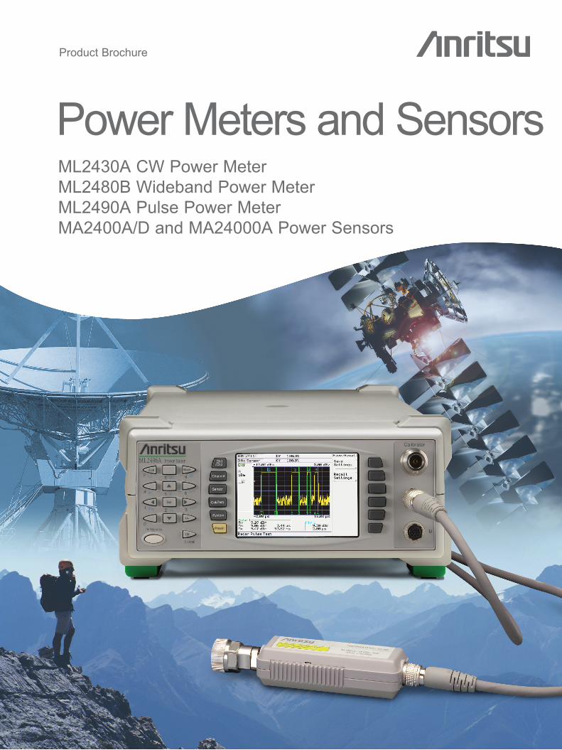
Product Brochure
Power Meters and SensorsML2430A CW Power Meter ML2480B Wideband Power Meter ML2490A Pulse Power Meter MA2400A/D and MA24000A Power Sensors

Anritsu Power Meters and Power Sensors: Accurate, Fast, and Affordable.Power MetersAnritsu offers a comprehensive range of power meters. The ML2490A series has the performance required for narrow fast rising-edge pulse power measurements (e.g. radar). The ML2480B series is suited for wide-band power measurements on signals such as LTE, W-CDMA, WLAN, and WiMAX. The ML2430A series of power meters are designed for CW applications, offering a combination of accuracy, speed and flexibility in a low cost package.
Power SensorsWith seven different families of power sensors (including USB sensors*) to choose from, you can trust you’ll find the right combination for precision power measurement, whatever your application.
* For more information on USB Sensors see “Microwave USB Power Sensors” Product Brochure/Technical Datasheet (11410-00504)
ML2490A Seriesn High Performance and Precision. 65 MHz instrument bandwidth, with 1 ns measurement resolution for precise rise-time
measurements of radar signals or for measuring the latest 4G Orthogonal Frequency Division Multiplexed (OFDM) signals.
n High Speed Sampling. Up to a 1 Gs/s sample rate produces accurate profiles of radar, LTE, W-CDMA, WLAN/WiMAX and other demanding signals. Displays peak, average and crest factor of any input signal.
n Triggering. Comprehensive circuitry provides precise triggering using internal or external sources. Continuous or single shot modes available.
n Measurement Gates and Markers. Multiple gates and markers for measuring: peak power, multi-pulse power, signal droop, rise-time and fall-time, pulse width, and Pulse Repetition Interval (PRI).
n External Video (ML2490A / ML2480B). Provides 1/4 VGA signal to external monitor (CRT or LCD).
n Ethernet Interface (ML2490A / ML2480B). 10/100BaseT LAN interface, allows remote control direct from a PC or local/wide-area network using dynamic (automatic) or static IP assignment.
Ideal solutions for average, peak, and pulse power measurements
2

3
Select the optimum Power Meter for your application
ML2480B Seriesn 20 MHz Instrument Bandwidth. Designed for accurate peak and average power measurements on a wide variety of signal
formats, including 3G/4G, WLAN and WiMAX technologies.n Continuous Wave (CW) Meter Mode. High accuracy and high dynamic range CW power measurements—the
50 MHz/1 GHz calibrator calibrates all Anritsu sensors. Frequency is automatically selected.n Soft Keys. Menu-driven operation simplifies test procedures.n Preset. Built-in measurement set-ups for widely available wireless systems, such as GSM, W-CDMA, WLAN and Bluetooth.n External Video (ML2490A / ML2480B). Provides 1/4 VGA signal to an external monitor (CRT or LCD).n Ethernet Interface (ML2490A / ML2480B). 10/100BaseT LAN interface allows remote control direct from a PC or
local/wide-area network using dynamic (automatic) or static IP assignment.
ML2430A Seriesn Fully-Featured General Purpose Power Meter. Ideal for CW applications, offering a combination of speed, accuracy and
flexibility in a low cost package.n Designed for Field Applications. Portable and rugged splash-resistant chassis design handles the roughest field treatment.
Add a front panel cover and soft case for further protection. There is also an optional NiMH battery, providing six hours continuous operation.
n Graphics Display. Provides graphical display of pulsed power or TDMA signals, displaying individual time slots. Frame triggering allows the user to measure the average power across a time slot.

Ready for the world’s most demanding applications
4
Radar Systems The high bandwidth and sample rate of the ML2480B and ML2490A provide accurate peak measurements on a variety of radar, radio-navigation and radio-location systems.
The ML2480B and ML2490A series have a number of features tailored for peak power measurement on pulsed systems. With a typical 8 ns rise-time, and a 1ns resolution on the measurement, the ML2490A and MA2411B power sensor have the performance to look at the rising-edge of radar signals.
Another benefit of the power meter is that it can be easily set up to trigger on a pulse or sequence of pulses. Users can set up to four independent gates to measure the average, max, and min powers on a sequence of pulses. The data for the max and min includes the timestamp and gives the user automatic display of the position and value of the maximum overshoot and minimum undershoot in each pulse.
Additional functionality highlights of ML2480B and ML2490A power meters include:n Automatic marker functions provide pulse rise-time, fall-time, off time and
Pulse Repetition Interval (PRI). A delta marker can be set up to measure the droop of the pulse top.
n Trigger event display is available as either arrows on the border of the screen or as an adjustable trigger event waveform. All timings for the gates and markers are taken from the trigger event.
n Read true output power – The offset table function corrects the power meter reading when the power meter is being used with a coupler or high power attenuator in a radar test system.
High resolution for observing fast rising-edge signals.
Accurate CW measurements.
Examine pulses in detail and capture the entire pulse train.

5
Measurement solutions for wireless systems
OFDM-based SolutionsOFDM-based technologies are playing an increasingly significant role in the design and installation of high-speed networks.
The ML2480B and ML2490A series have been designed to meet the challenge of today’s fast-paced technology change. Users can measure the peak power of wideband OFDM systems (such as WLAN, WiMAX, and LTE) and configure the display to measure average and peak power. CCDF, CDF and PDF statistical functions for OFDM measurements are also available. Dithered sampling ensures accurate measurements on wideband, high-data rate carriers when continuously transmitting.
The wide bandwidth of the signal channel allows for precise placement of measurement gates. Users can hone in their analysis by taking advantage of the multiple gate facility and measuring precise sections of the signal, such as the OFDM training sequence at the start of the 802.11g signal and the data payload section. Or users can take advantage of a built-in preset to instantly set up and measure continuous OFDM signals.
3G CDMA SystemsDesigned to measure the peak power of all the major CDMA systems in the world, the ML2480B and ML2490A series covers all your requirements, including those associated with Time Division Duplexing such as TD-SCDMA.
Users can configure the display to measure average and peak power as well as crest factor during the measurement period for FDD systems. TDD systems can be displayed as a graph profile and the measurement gates can be set to measure and display the peak and crest factor during the data payload trans-mission.
GSM/EDGE/GPRS SystemsFor GSM systems, the power meter is set up to trigger on the GSM pulse. The active gate is set up to measure the power within the 10% to 90% section of the burst profile in order to meet the specified limits. An automatic limit can be used to give a pass or fail indication. The display shows the results from the active gate, indicating the average power within the burst.
Measurement gates and markers for ob-serving precise sections of the signal.
Built-in statistical analysis tool.
EDGE and GPRS measurements made simple.
Determine signal crest factor with ease.

6
The Information you need, right where you want it
Make house calls without leaving the lab.
Amplifier Measurements Power amplifiers designed for peak applications, whether pulsed or CDMA, cannot operate at full peak power under CW test conditions. The gain and output power can only be measured accurately using a peak power meter under representative conditions.
For the precise characterization of amplifier output power and gain, the ML2438A/88B/96A power meters are true dual channel meters, with two independent signal channels that eliminate the need for multiplexing. Gain and output power are measured simultaneously. Fast responding diode sensors respond immediately to changes in power level to reduce total test time.
With the ML2496A and ML2488B, users can also make Power-Added Efficiency (PAE) measurements. The amplifier bias voltage can be entered manually or over GPIB and the bias current can be measured using a current probe connected directly to the power meter.
Return Loss Measurements Take advantage of the power meter’s dual inputs to measure the return loss of an amplifier under correct operating conditions.
Frequency Sweep and Power Sweep The Anritsu ML2400A series of power meters are designed to function with Anritsu MG3690C synthesized generators to form an integrated test solution for swept power and frequency measurements.
The MG3690C requires Analog Sweep Option 6 to be fitted for this function.
Remote Monitoring The ML2430A series automatically calls a pre-entered phone number whenever a limits threshold is exceeded. Just set the limit level, enter the phone number and connect a modem.
The ML2430A’s data acquisition settings can also adjust to monitor average power or the burst power of specific timeslots. The RS232 port uses the same commands as the GPIB.

7
Features loaded into every Power Meter
Dual Display Channel Each display channel in the Anritsu ML2480B/90A Power Meter is a measurement set up and can use any selection or combination of the sensor inputs. View one display channel or two. Switch between display channels quickly via the front panel hard ‘hot’ key. The user can also choose to view the measurement results as a graph profile or numerical readout.
Sampling Modes The ML2490A series power meter automatically chooses between continuous (time capture above 3.2 µs) or repetitive (50 ns to 3.2 µs) sampling to build up the trace to 1 ns settable display resolution. The ML2480B provides up to 62.5 MS/s sampling with resolution of 16 ns. The user may also opt to adjust the sample rate directly.
Test Limits n A simple power limit can be set up for many applications to test the upper and/
or lower boundaries of the signal. n A time varying limit line can be set up for pulsed systems such as radar,
TDMA cellular systems or WLAN to test all aspects of the pulse profile.
Set-up Recall Conveniently recall application-specific measurement set-ups.
Secure ModeThe power meter series have a secure mode for operation in security sensitive environments. On activation, the secure mode wipes all information stored in the non-volatile RAM on power up.
GPIBComprehensive c ommand-set for full functionality over GPIB.
RS232For control and firmware updates.
Analog Voltage InputMeasures voltage or accepts the V/GHz signal from a synthesiser for automated sensor calibration factor correction or Power Added Efficiency (PAE) measurements.
Analog OutputsSupports corrected and scaled measurements or real-time dual channel output. Synthesiser interface controls include zero blanking.
Flexible measurement display.
Time-varying limits, user-defined or Preset.

PowerMax™ – PC remote user interface
8
PowerMax™ is a free graphical user-interface software program, for the ML2490A and ML2480B Power Meter* series. PowerMax runs on a standard PC** and communicates with the power meter via an Ethernet interface.
PowerMax provides an enhanced visualization of an instrument display and simplified remote control, allowing:
n Continuous view of measurement traces in real-timen Multiple gates and markers readings displayed at-a-glancen Archiving or printing of data and plots for future analysis
PowerSuite™Free software is available for ML243xA power meters to continuously view measurement traces on the PC in real-time or archive data and plots for future analysis. PowerSuite runs on a standard PC** via GPIB or RS232.
*Requires firmware v2.20 or greater. **For PC requirements, see Technical Datasheet

9
Discover a comprehensive range of Power Sensors
The Anritsu family of power sensors designed to cover a wide range of measurement applications.
Power Sensors for every applicationAnritsu’s power sensors have been designed with just one thing in mind: everything. The range of sensors provide frequency coverage to 50 GHz, with dynamic range up to 90 dB, and includes both diode and thermal based technologies.
The Anritsu diode-based sensors offer speed, sensitivity, and dynamic range with designs using half- or full-wave diode rectifiers constructed from zero-bias Schottky diodes. The rectifier output is low-pass filtered, forming an envelope detector. This post-detection bandwidth is sometimes referred to as the video bandwidth and is a measure of how quickly the power sensor can respond to a changing input signal, such as a radar pulse or a multi-carrier OFDM signal.
Pulse and Wideband Sensors: MA2490/91A and MA2411BThe MA2490A and MA2491A have been designed as dual-purpose, wideband and CW sensors. An FET switch is used to chop the signal from the sensor, to improve stability at low power levels, in CW mode. These sensors have 20 MHz video bandwidth (and 18 ns rise-time in the pulse modulated mode), and can be used to make average and peak power factor measurements on signals with rapid amplitude change, such as those in 3G/4G, WLAN, WiMAX and radar systems.
The MA2411B pulse sensor has been specifically designed for a wide video bandwidth of 50 MHz, providing a fast rise-time of better than 8 ns. This power sensor does not contain a FET switch for low-level CW applications. Use this sensor for the most demanding rising-edge measurements, such as radar and OFDM, multi-carrier signals.
Standard Diode Sensors: MA2470DDesigned for high dynamic range, high accuracy CW and TDMA measurements, these power sensors have 90 dB dynamic range and linearity better than 1.8%. This makes them the choice for precision measurements. The rise-time of these sensors is fast enough for power measurements on GSM and similar TDMA systems that use GMSK modulation.
High Accuracy Diode Sensors: MA2440D With its built in 3 dB attenuator, the MA2440D sensors minimize input VSWR. They are typically used when high measurement accuracy is required over a large dynamic range, for example when measuring amplifiers. High accuracy diode sensors have a dynamic range of 87 dB compared to the 90 dB of standard diode sensors. In all other respects, the performance of the sensors is identical to the standard diode sensor.
Universal Power Sensors: MA2480D The MA2480A series are true RMS sensors with a dynamic range of 80 dB. These power sensors are modulation independent and can be used for average power measurements on a wide variety of signals, including multi-tone or W-CDMA signals. The sensor architecture consists of three pairs of diodes, each one configured to work in its square law region over the dynamic range of the sensor. Option 1 provides TDMA measurement capability, calibrating one of the diode pairs for linearity over a wide dynamic range.

10
Thermal Power Sensors: MA24000AThe Anritsu MA24000A series thermal sensors provide excellent power measurement accuracy over 50 dB of dynamic range. Thermal sensors use Seebeck elements, where the combined effect of a thermal gradient and charge migration between dissimilar metals gives a true reading of the average power of any incident waveform. Anritsu thermal sensors have class leading SWR and a built-in EEPROM with calibration factor and linearity correction data. This results in assured accuracy when measuring any signal.
Power Sensors for every application
Sensor EEPROMThe family of Anritsu power sensors store calibration data and model information within internal EEPROMS. User calibration factor tables allow frequency points or compensation for test system loss, including that from couplers and attenuators.
High Power ApplicationsTraditional high-power sensors are expensive and have degraded accuracy specifications. Having additional specialized sensors lead to more annual calibrations requiring more down time and expense. Using user calibration factor tables coupled with a precision high power attenuator avoids these problems and eliminates the need for specialized, high-power. Users can easily reduce operating costs and save time:n Compensation can be made for any precision attenuator or coupler by entering frequency and attenuation values into the
user calibration factor table in the internal EEPROM.n The attenuation device can be semi-permanently attached. The power meter automatically applies compensation during
the 0.0 dBm, 50 MHz calibration reference process.n User calibration factor tables are easily deactivated – allowing the power sensor to be used as a stand-alone device.n Up to six tables can be stored.
Sensor and Power Meter SelectionSensors Standard Diode (High Accuracy) Diode Universal Wideband Pulse Thermal
MA2470D Series MA2440D Series MA2480D Series MA249XA Series MA2411B MA2400xA
Power Measurement Average (RMS) Average (RMS) Average (RMS) Average (RMS), Peak Average (RMS), Peak Average (RMS)Measurement Application (Examples)
CW, GMSK,GFSK, 8PSK CW, GMSK CW, GMSK, GFSK,
8PSK, QPSK, QAMCW, GMSK, 8PSK, QPSK, QAM Pulse, QAM Any modulation
TDMA, FDMA, IS136 TDMA, FDMA TDMA, FDMA, CDMA, OFDM, Radar
TDMA, FDMA, CDMA, OFDM, Radar Radar, OFDM Any access scheme
Compatible Power Meters ML24xxA/B ML24xxA/B ML24xxA/B ML2480A/B,
ML2490AML2480A/B, ML2490A ML24xxA/B
11
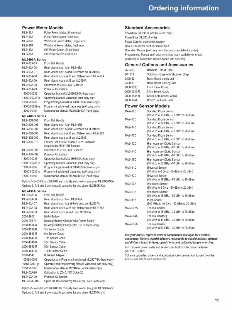
Ordering information
Power Meter ModelsML2495A Pulse Power Meter, Single InputML2496A Pulse Power Meter, Dual InputML2487B Wideband Power Meter, Single InputML2488B Wideband Power Meter, Dual InputML2437A CW Power Meter, Single InputML2438A CW Power Meter, Dual Input
ML2490A SeriesML2400A-05 Front Bail Handle ML2490A-06 Rear Mount Input A on ML2495A ML2490A-07 Rear Mount Input A and Reference on ML2495AML2490A-08 Rear Mount Inputs A, B and Reference on ML2496AML2490A-09 Rear Mount Inputs A, B on ML2496AML2490A-98 Calibration to Z540, ISO Guide 25ML2490A-99 Premium Calibration13000-00238 Operation Manual ML2480B/90A (hard copy)13000-00238-ja Operating Manual: Japanese (soft copy only)13000-00239 Programming Manual ML2480B/90A (hard copy)13000-00239-ja Programming Manual: Japanese (soft copy only)13000-00164 Maintenance Manual ML2480B/90A (hard copy)ML2480B SeriesML2480B-005 Front Bail HandleML2480B-006 Rear Mount Input A on ML2487BML2480B-007 Rear Mount Input A and Reference on ML2487BML2480B-008 Rear Mount Inputs A, B and Reference on ML2488BML2480B-009 Rear Mount Inputs A, B on ML2488BML2480B-015 Factory Fitted 50 MHz and 1 GHz Calibrator
(required by MA2411B Sensor)ML2480B-098 Calibration to Z540, ISO Guide 25ML2480B-099 Premium Calibration13000-00238 Operation Manual ML2480B/90A (hard copy)13000-00238-ja Operating Manual: Japanese (soft copy only)13000-00239 Programming Manual ML2480B/90A (hard copy)13000-00239-ja Programming Manual: Japanese (soft copy only)13000-00164 Maintenance Manual ML2480B/90A (hard copy)Options 5, 2400-82, and 2400-83 are mutually exclusive for any given ML2480B/90A.Options 6, 7, 8 and 9 are mutually exclusive for any given ML2480B/90A.
ML2430A SeriesML2400A-05 Front Bail HandleML2400A-06 Rear Mount Input A on ML2437AML2400A-07 Rear Mount Input A and Reference on ML2437AML2400A-08 Rear Mount Inputs A, B and Reference on ML2438AML2400A-09 Rear Mount Inputs A and B on ML2438A2000-1603 NiMH Battery2000-996-R Desktop Battery Charger with Power Supply2000-1534-R Desktop Battery Charger (for use in Japan only)2000-1538-R 3m Sensor Cable2000-1539-R 5m Sensor Cable2000-1540-R 10m Sensor Cable2000-1541-R 30m Sensor Cable2000-1542-R 50m Sensor Cable2000-1543-R 100m Sensor Cable2000-1545 Bulkhead Adapter10585-00001 Operation and Programming Manual ML2437/8A (hard copy)10585-00001-ja Operation and Programming Manual: Japanese (soft copy only)10585-00003 Maintenance Manual ML2400A Series (hard copy)ML2400A-98 Calibration to Z540, ISO Guide 25ML2400A-99 Premium CalibrationML2400A-30A Option 30, Operation/Prog Manual (for use in Japan only)
Options 5, 2400-82, and 2400-83 are mutually exclusive for any given ML2430A unit.Options 6, 7, 8 and 9 are mutually exclusive for any given ML2430A unit.
Standard AccessoriesPowerMax (ML249xA and ML248xB only)PowerSuite (ML243xA only)Power Cord for destination countryOne 1.5 m sensor cord per meter input Operation Manual (soft copy only; hard-copy available for order)Programming Manual (soft copy only; hard-copy available for order)Certificate of Calibration (also included with sensors)
General Options and Accessories760-209 Hardside Transit CaseD41310 Soft Carry Case with Shoulder Strap2400-82 Rack Mount, single unit2400-83 Rack Mount, side-by-side2000-1535 Front Panel Cover2000-1536-R 0.3m Sensor Cable2000-1537-R Spare 1.5m Sensor Cable2000-1544 RS232 Bootload Cable
Power Sensor ModelsMA2472D Standard Diode Sensor
(10 MHz to 18 GHz, –70 dBm to 20 dBm)MA2473D Standard Diode Sensor
(10 MHz to 32 GHz, –70 dBm to 20 dBm)MA2474D Standard Diode Sensor
(10 MHz to 40 GHz, –70 dBm to 20 dBm)MA2475D Standard Diode Sensor
(10 MHz to 50 GHz, –70 dBm to 20 dBm)MA2442D High Accuracy Diode Sensor
(10 MHz to 18 GHz, –67 dBm to 20 dBm)MA2444D High Accuracy Diode Sensor
(10 MHz to 40 GHz, –67 dBm to 20 dBm)MA2445D High Accuracy Diode Sensor
(10 MHz to 50 GHz, –67 dBm to 20 dBm)MA2481D Universal Sensor
(10 MHz to 6 GHz, –60 dBm to 20 dBm)MA2482D Universal Sensor
(10 MHz to 18 GHz, –60 dBm to 20 dBm)MA2490A Wideband Sensor
(50 MHz to 8 GHz, –60 dBm to 20 dBm)MA2491A Wideband Sensor
(50 MHz to 18 GHz, –60 dBm to 20 dBm)MA2411B Pulse Sensor
(300 MHz to 40 GHz, –20 dBm to 20 dBm)MA24002A Thermal Sensor
(10 MHz to 18 GHz, –30 dBm to 20 dBm)MA24004A Thermal Sensor |
(10 MHz to 40 GHz, –30 dBm to 20 dBm)MA24005A Thermal Sensor
(10 MHz to 50 GHz, –30 dBm to 20 dBm)
See your Anritsu representative or components catalogue for available attenuators, limiters, coaxial adapters, waveguide-to-coaxial adapter, splitters and dividers, loads, bridges, open/shorts, and calibrated torque wrenches. For complete power meter and sensor specifications; technical datasheet p/n: 11410-00423.Software upgrades, drivers and application notes can be downloaded from the Anritsu web site at www.anritsu.com

11410-00408, Rev. F Printed in United States 2013-01 ©2013 Anritsu Company. All Rights Reserved.
® Anritsu All trademarks and registered trademarks are the property of their respective owners. Data subject to change without notice. For the most recent specifications visit: www.anritsu.com
• United States Anritsu Company1155 East Collins Boulevard, Suite 100, Richardson, TX, 75081 U.S.A. Toll Free: 1-800-ANRITSU (267-4878) Phone: +1-972-644-1777 Fax: +1-972-671-1877• Canada Anritsu Electronics Ltd.700 Silver Seven Road, Suite 120, Kanata, Ontario K2V 1C3, Canada Phone: +1-613-591-2003 Fax: +1-613-591-1006
• Brazil Anritsu Electrônica Ltda.Praça Amadeu Amaral, 27 - 1 Andar 01327-010 - Bela Vista - São Paulo - SP - Brazil Phone: +55-11-3283-2511 Fax: +55-11-3288-6940
• Mexico Anritsu Company, S.A. de C.V.Av. Ejército Nacional No. 579 Piso 9, Col. Granada 11520 México, D.F., México Phone: +52-55-1101-2370 Fax: +52-55-5254-3147
• United Kingdom Anritsu EMEA Ltd.200 Capability Green, Luton, Bedfordshire LU1 3LU, U.K. Phone: +44-1582-433280 Fax: +44-1582-731303
• France Anritsu S.A.12 avenue du Québec, Batiment Iris 1-Silic 612, 91140 VILLEBON SUR YVETTE, France Phone: +33-1-60-92-15-50 Fax: +33-1-64-46-10-65
• Germany Anritsu GmbHNemetschek Haus, Konrad-Zuse-Platz 1 81829 München, Germany Phone: +49 (0) 89 442308-0 Fax: +49 (0) 89 442308-55
• Italy Anritsu S.r.l.Via Elio Vittorini 129 00144 Roma Italy Phone: +39-06-509-9711 Fax: +39-06-502-2425
• Sweden Anritsu ABBorgafjordsgatan 13A, 164 40 KISTA, Sweden Phone: +46-8-534-707-00 Fax: +46-8-534-707-30
• Finland Anritsu ABTeknobulevardi 3-5, FI-01530 Vantaa, Finland Phone: +358-20-741-8100 Fax: +358-20-741-8111
• Denmark Anritsu A/S (for Service Assurance) Anritsu AB (for Test & Measurement)Kay Fiskers Plads 9, 2300 Copenhagen S, Denmark Phone: +45-7211-2200 Fax: +45-7211-2210
• RussiaAnritsu EMEA Ltd. Representation Office in RussiaTverskaya str. 16/2, bld. 1, 7th floor. Russia, 125009, Moscow Phone: +7-495-363-1694 Fax: +7-495-935-8962
• United Arab Emirates Anritsu EMEA Ltd. Dubai Liaison OfficeP O Box 500413 - Dubai Internet City Al Thuraya Building, Tower 1, Suite 701, 7th Floor Dubai, United Arab Emirates Phone: +971-4-3670352 Fax: +971-4-3688460
• Singapore Anritsu Pte. Ltd.60 Alexandra Terrace, #02-08, The Comtech (Lobby A) Singapore 118502 Phone: +65-6282-2400 Fax: +65-6282-2533
• India Anritsu India Private Limited2nd & 3rd Floor, #837/1, Binnamangla 1st Stage, Indiranagar, 100ft Road, Bangalore - 560038, India Phone: +91-80-4058-1300 Fax: +91-80-4058-1301
• P. R. China (Shanghai) Anritsu (China) Co., Ltd.Room 1715, Tower A CITY CENTER of Shanghai, No. 100 Zunyi Road, Chang Ning District, Shanghai 200051, P.R. China Phone: +86-21-6237-0898 Fax: +86-21-6237-0899
• P. R. China (Hong Kong) Anritsu Company Ltd.Unit 1006-7, 10/F., Greenfield Tower, Concordia Plaza, No. 1 Science Museum Road, Tsim Sha Tsui East, Kowloon, Hong Kong, P. R. China Phone: +852-2301-4980 Fax: +852-2301-3545
• Japan Anritsu Corporation8-5, Tamura-cho, Atsugi-shi, Kanagawa, 243-0016 Japan Phone: +81-46-296-1221 Fax: +81-46-296-1238
• Korea Anritsu Corporation, Ltd.502, 5FL H-Square N B/D, 681, Sampyeong-dong, Bundang-gu, Seongnam-si, Gyeonggi-do, 463-400 Korea Phone: +82-31-696-7750 Fax: +82-31-696-7751
• Australia Anritsu Pty Ltd.Unit 21/270 Ferntree Gully Road, Notting Hill, Victoria 3168, Australia Phone: +61-3-9558-8177 Fax: +61-3-9558-8255
• Taiwan Anritsu Company Inc.7F, No. 316, Sec. 1, Neihu Rd., Taipei 114, Taiwan Phone: +886-2-8751-1816 Fax: +886-2-8751-1817
Anritsu prints on recycled paper with vegetable soybean oil ink.
Please Contact: