Embed Size (px)
Citation preview

Polarimetric Phased-Array Radar for Weather Measurement: A Planar orCylindrical Configuration?
GUIFU ZHANG
School of Meteorology, and School of Electrical and Computer Engineering, and Atmospheric Radar Research Center,
University of Oklahoma, Norman, Oklahoma
RICHARD J. DOVIAK AND DUSAN S. ZRNIC
School of Meteorology, and School of Electrical and Computer Engineering, University of Oklahoma, and NOAA/National
Severe Storms Laboratory, Norman, Oklahoma
ROBERT PALMER
School of Meteorology, and Atmospheric Radar Research Center, University of Oklahoma, and NOAA/National
Severe Storms Laboratory, Norman, Oklahoma
LEI LEI
School of Electrical and Computer Engineering, and Atmospheric Radar Research Center, University of
Oklahoma, Norman, Oklahoma
YASSER AL-RASHID
Lockheed Martin Corporation, Moorestown, New Jersey
(Manuscript received 22 March 2010, in final form 10 September 2010)
ABSTRACT
This paper suggests a cylindrical configuration for agile beam polarimetric phased-array radar (PPAR) for
weather surveillance. The most often used array configuration for PAR is a planar array antenna. The planar
configuration, however, has significant deficiencies for polarimetric measurements, as well as other limita-
tions, such as increases in beamwidth, decreases of sensitivity, and changes in the polarization basis when the
beam scans off its broadside. The cylindrical polarimetric phased-array radar (CPPAR) is proposed to avoid
these deficiencies. The CPPAR principle and potential performance are demonstrated through theoretical
analysis and simulation. It is shown that the CPPAR has the advantage of a scan-invariant polarization basis,
and thus avoids the inherent limitations of the planar PPAR (i.e., PPPAR).
1. Introduction
In addition to military applications for target rec-
ognition and tracking (Brookner 2008), phased-array
radar (PAR) technology has recently been successfully
introduced to the weather community. The nation’s first
phased-array weather radar, the National Weather Radar
Testbed (NWRT) operating at a wavelength of 9.38 cm,
was developed in Norman, Oklahoma, through a joint
effort of a government–university–industry team (Zrnic
et al. 2007). The NWRT demonstrated that its pulse-to-
pulse electronic beam-steering capability enables meteo-
rological measurements that are as accurate in shorter
storm surveillance times as those achieved with a conven-
tional dish antenna with a mechanically steered beam. The
shorter surveillance times result in faster data updates and
offer the capability to observe detailed evolutions of se-
vere storm phenomena (Yu et al. 2007; Heinselman et al.
2008). The NWRT also has a hybrid capability to both
mechanically and electronically steer the beam. This ca-
pability has allowed multipattern measurements of the
Corresponding author address: Dr. Guifu Zhang, School of
Meteorology, University of Oklahoma, 120 David L. Boren Blvd.,
Suite 5900, Norman, OK 73072.
E-mail: [email protected]
JANUARY 2011 Z H A N G E T A L . 63
DOI: 10.1175/2010JTECHA1470.1
Unauthenticated | Downloaded 02/17/22 08:23 AM UTC
same meteorological volume to successfully mitigate both
stationary and moving clutter (Zhang et al. 2011). Fur-
thermore, the NWRT uses an antenna from the AN/
SPY1-A monopulse radar of the Aegis system (Sherman
1988), which has sum and difference channels; these can
be combined to implement a spaced-antenna interferom-
etry (SAI) technique for crossbeam wind measurement
(Zhang and Doviak 2007) and subvolume inhomogeneity/
object detection (Zhang and Doviak 2008). It has been
also theorized that the AN/SPY1-A auxiliary channels
could support the implementation of adaptive clutter
cancellation techniques (Le et al. 2009).
While PAR technology has recently received wide-
spread attention in the weather community, weather radar
polarimetry has matured to a point that it is being imple-
mented on the national network of Weather Surveillance
Radar-1988 Doppler (WSR-88D) radars (Doviak et al.
2000) using its conventional dish antenna. Polarimetric
radar provides multiparameter measurements that reveal
detailed microphysics of storms in addition to hydrome-
teor classification, accurate precipitation estimation, and
improved weather nowcasts. Therefore, the weather com-
munity and the nation expect that the future multifunction
phased-array radar (MPAR) will retain all of the capa-
bilities of the polarimetric WSR-88D (Smith et al. 2008).
It is the polarimetric capability that the second MPAR
symposium (online at http://www.ofcm.noaa.gov/mpar-
symposium) identified as the most challenging technical
issue that the community is facing.
The challenge comes from the fact that highly accurate
polarimetric radar measurements are required to provide
meaningful information. However, biases inherent to pla-
nar polarimetric phased-array radar (PPPAR) exist and
can be larger than the intrinsic values if the beam is di-
rected away from the planar array’s broadside. For ex-
ample, the intrinsic ZDR values range only from about
0.1 dB for drizzle and dry snow to 3–4 dB for heavy rain
and large drops. Thus, it is desirable that the measurement
error for ZDR be of the order of 0.1 dB (Zhang et al. 2001;
Brandes et al. 2003). However, the ZDR bias for a PPPAR
can be a few decibels (Zhang et al. 2009a). Hence, it is
crucial for the success of the MPAR project that the sys-
tem configuration for a PPPAR is selected correctly and
designed optimally.
Currently, the possible antenna array configurations
include linear array, planar array, circular/cylindrical ar-
ray, and spherical array. The linear array needs one me-
chanic rotation for weather surveillance like the rapid
Doppler on Wheels (rapid DOW; see Wurman 2003) and
the proposed design for the Center for Collaborative
Adaptive Sensing of the Atmosphere (CASA) instrument
(Hopf et al. 2009). For the planar array, multiple faces
(normally four) are needed (e.g., the SPY-1A), but the
planar array has sensitivity loss and polarization bias if
the beam points away from the broadside (Zhang et al.
2009a). A circular or cylindrical configuration has been
used for direction finding and communications (Royer
1966; Raffaelli and Johansson 2003). For satellite com-
munication applications, the spherical array is optimal and
flexible in its use of the antenna aperture size and in its
symmetry (Tomasic et al. 2002). For weather applications,
however, the spherical array cannot provide the high
cross-polar isolation required to accurately measure pre-
cipitation.
In this study, we examine cylindrical polarimetric phased-
array radar (CPPAR) for practically scan-invariant weather
measurements. The CPPAR has azimuth scan-invariant
properties and has very minor dependence on elevation at
low elevation angles. Because the WSR-88D scan strategy
has coarser elevation sampling at higher elevation angles,
and because the CPPAR’s angular resolution coarsens as
beam elevation angle increases (thus filling angular gaps
created by coarser sampling), the gradual decrease in ele-
vation resolution is a beneficial feature. In section 2 the
meteorological measurements with a PPPAR are simulated
and the PPPAR’s deficiencies are revealed. In section 3, a
cylindrical array configuration is described and the CPPAR
performance is quantified through a theoretical analysis and
simulation. An example design and simulation results are
given in section 4. Summary and discussions are provided in
the last section.
2. Issues with a PPPAR
For a PPPAR, three or four faces are normally used to
cover the 3608 in azimuth. Because the antenna faces and
their broadside directions are fixed, the beam and po-
larization characteristics change depending on the elec-
tronic beam direction. To obtain an intuitive impression,
we show KOUN (a prototype dual-polarized WSR-88D)
measurements of reflectivity and differential reflectivity
in Fig. 1. Also shown are the simulated measurements
that would be made by a four-face PPPAR comprising an
array of crossed dipoles, and those if each face had the
same size aperture as KOUN. Crossed Hertzian dipoles
are used for sake of simplicity without having to specify
the design and size of the array elements. Although other
types of antenna elements (e.g., a patch) can be simu-
lated in a similar way, detection performance would be
worse because these elements have increased directive
gain and thus have a larger scanning loss. Furthermore,
ZDR bias would still exist, but it is correctable (Zhang
et al. 2009a).
It can be seen that the reflectivity and differential re-
flectivity measurements are the same as those of KOUN at
the four broadside directions. However, the measurements
64 J O U R N A L O F A T M O S P H E R I C A N D O C E A N I C T E C H N O L O G Y VOLUME 28
Unauthenticated | Downloaded 02/17/22 08:23 AM UTC

are considerably different at beam positions away from
the broadsides: (i) ZH sensitivity is lost and (ii) ZDR has
significant bias. There is a 7.5-dB sensitivity loss for the
horizontally polarized beam if it is 458 from the broad-
side (it would be a 15-dB loss if the three-face PPPAR
were used and the beam was 608 from the broadside).
This is due to the combined effect of the decreased gain
of the horizontal dipole radiation pattern and the de-
creased gain of the array caused by the smaller projected
aperture in directions away from broadside. In addition
to the 7.5-dB sensitivity loss for horizontally polarized
waves, vertically polarized waves also have some loss
(i.e., 1.5 dB) for beams steered to 458 from broadside.
Although the biases in the reflectivity factor and differ-
ential reflectivity seen in Figs. 1c,d are correctable, sen-
sitivity loss can only be compensated by increased power
or aperture size.
The scan-variant measurements are unacceptable to
meteorologists unless the data are calibrated to remove
the radar system effects (Zhang et al. 2009a). Although
the ZDR bias can be compensated, the sensitivity lost and
worsening angular resolution is costly to recover. One
might think to use the vertical polarization for the prime
reflectivity measurements, but there will still be loss due to
the projected area being diminished, and the azimuthal
resolution will be worse byffiffiffi2p
. Furthermore, the lost sen-
sitivity and angular resolution for other polarimetric mea-
surements (ZDR, rhv, and fDP) is also costly to recover
because the antenna size and/or transmitter power both
need to be increased.
For meteorological applications, the four-face PPPAR’s
gain and beamwidth changes are most significant for beams
that are electronically steered in azimuth. To compensate
for the 7.5-dB loss (i.e., for horizontally transmitted waves
at the azimuth limits of 6458), without increasing trans-
mitted power, the antenna aperture would need to be in-
creased by a factor of 5.66 in the horizontal direction; this
is clearly a prohibitively expensive solution. Alternatively,
to ensure that the beamwidth at 6458 is practically equal
to the beamwidth in elevation, and is no worse than the
beamwidth of the WSR-88D, the antenna size in the
horizontal direction must be increased by a factor offfiffiffi2p
;
FIG. 1. A comparison of images obtained with (a),(b) a mechanically steered beam of the polarimetric KOUN radar
and that obtained with (c),(d) a simulated four-face PPPAR and its electronically steered beam.
JANUARY 2011 Z H A N G E T A L . 65
Unauthenticated | Downloaded 02/17/22 08:23 AM UTC

however, in this case the transmitter power would need to
be increased by a factor of 4 to not lose detection capa-
bility. Thus, the aperture size of the planar PPAR needs to
be 8.54/cos(108) m in the vertical plane, and 12.08 m in the
horizontal, which is significantly larger than the WSR-88D
reflector diameter. The dimension in the vertical plane
assumes that the array face is tilted 108 from the vertical to
provide a vertical beamwidth at zero degrees of elevation
to match the WSR-88D’s beamwidth. Clearly there is
motivation to decrease the array size while matching the
WSR-88D capabilities, and with this in mind the cylin-
drical array is examined.
3. Configuration and formulation for CPPAR
Realizing the deficiencies of a PPPAR for weather
measurements, we propose a CPPAR (see Zhang et al.
2009b).
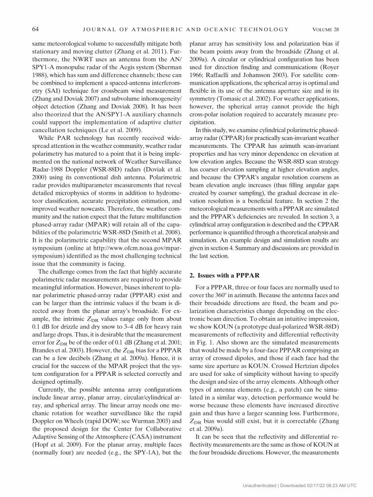
As sketched in Fig. 2, there are M 3 N dual-polarized
radiating elements arranged azimuthally (M) and axially
(N) on the surface of a cylinder. Multiple simultaneous
beams are formed with each beam generated from a sector
of the cylindrical surface with the broadside direction along
the bisector of the illuminated sector. Using CPPAR, po-
larization orthogonality is preserved in all directions.
To study the radiation characteristics of a CPPAR, we
choose a coordinate system with its z direction along the
cylinder’s axis (Fig. 3). An array element (mn: mth row,
nth column), comprised of crossed h and v dipoles is lo-
cated at fn, zm on the cylindrical surface at rmn 5 axR
cosfn 1 ayR sinfn 1 azzm, where R is the cylinder’s ra-
dius, the row height zm ranges from 2D/2 to 1D/2, where
D is the axial length of the cylindrical array (equal to the
diameter D of the WSR-88D), and the bold unit vectors
represent the Cartesian coordinates (ax, ay, az) (Fig. 3). Az-
imuth location fn is measured relative to the x axis and is
fn 5 nDf, n 5 1, 2, 3, . . . . The electric field at r 5 axr sinu
cosf 1 ayr sinu sinf 1 azr cosu, transmitted by the mnth q
(i.e., q 5 h or v) dipole, is (Ishimaru 1997, section 2.4)
E(q)mn(r) 5 � k2e�jkjr�r
mnj
4p« r� rmn
�� ��M(q)mn(u, f), (1a)
where k 5 2p/l, l is the radar wavelength, « is the
permittivity for an assumed uniform precipitation-free
atmosphere,
M9(q)mn (u, f) 5 ar 3 [ar 3 M(q)
mn] (C m21), (1b)
where M9(q)mn is the moment of dipole q at location mn,
and ar is the unit vector along r.
Using the far-field approximation, we have the elec-
tric field at r radiated by the mnth q dipole
E(q)mn 5
E(h)mn
E(v)mn
" #’ Aejk[z
mcosu1Rsinucos(f�f
n)] M9(h)
mn
M9(v)mn
" #,
(2a)
where
A [�k2e�jkr
4p«r. (2b)
In this paper superscripts (h) and (v) are used to identify
the horizontal and vertical dipoles, repsectively. Follow-
ing the procedure of Zhang et al. (2009a), we can express
the electric fields in the plane of polarization (Doviak and
Zrnic 2006, their Fig. 8.15) at r as
E(h)mn 5 E
(h)tmne(h)
n and (3a)
FIG. 2. The CPPAR with a pair of dipoles for each array element.
FIG. 3. Coordinate system for CPPAR element radiation.
66 J O U R N A L O F A T M O S P H E R I C A N D O C E A N I C T E C H N O L O G Y VOLUME 28
Unauthenticated | Downloaded 02/17/22 08:23 AM UTC

E(v)mn 5 E
(v)tmne(v), (3b)
where E(h)tmn and E
(v)tmn are the fields respectively trans-
mitted by the h and v dipoles along the normal to the plane
of the dipoles (i.e., the crossed dipole’s broadside di-
rection) located at fn, zm. Thus,
E(h)tmn 5 Aejk[z
mcosu1R sinucos(f�f
n)]M(h)
mn, (3c)
with a like expression for E(v)tmn and en
(h) is
e(h)n 5 a
y9� [a
x9sinucos(f� f
n)
1 ay9
sinusin(f� fn) 1 a
zcosu] sinusin(f� f
n),
(3d)
a form analogous to Eq. (5a) of Zhang et al. (2009a), but
one that accounts for the fn angular rotation about z of
the coordinate x, y axes to x9, y9 for the mnth element.
Here, e(v) is
e(v) 5 az
sin2u� [ax9
cosf 1 ay9
sinf] sinu cosu, (3e)
which is identical to that given by Eq. (5b) of Zhang et al.
(2009a). Note that en(h) is a function of dipole location but
e(v) is not and, as pointed out by Zhang et al. (2009a), en(h)
is not orthogonal to e(v).
To form a beam pointing in the (u0, f0) direction,
a phase shift
cmn
5�k[zm
cosu0
1 R sinu0
cos(f0� f
n)] (4)
is applied to each of the mn elements that are used to
form the beam. The phase shifts given by (4) produce
a beam in the (u0, f0) direction.
The incident horizontal and so-called ‘‘vertical’’ (i.e.,
the vertical field lies in the vertical plane, but is only
vertical at the 908 zenith angle) fields Eihmn and Eivmn in
the plane of polarization are given by (Zhang et al. 2009a)
Eihmn
Eivmn
� �5 AP
mn
jM(h)mnj
jM(v)mnj
" #exp jc(0)
mn
h i, (5a)
where c(0)mn 5 k zm[cosu� cosu0] 1 R[sinucos(f� fn)
�� sinu0cos (f0 � fn)]g, and
Pmn
5cos(f� f
n) 0
�cosusin(f� fn) sinu
� �(5b)
is a matrix that projects the elements’ broadside electric
field to the plane of polarization at r, and accounts
for h dipole orientation at fn. In this analysis we assume
that each dipole radiates only into the outward hemisphere
with an equator in the plane of the crossed dipole element.
Magnitude signs are placed around the dipole moment to
emphasize that the dipole phase is incorporated into C(0)mn.
Although the subscript index m does not appear in the
matrix, it is attached to Pmn to emphasize that the pro-
jection applies to the mnth h and v dipoles. The subscript
h and v on Eihmn and Eivmn denotes these are the hori-
zontal and vertical fields transmitted by the mnth dipoles
and incident on the scatterer; note that Eivmn has contri-
butions from both the h and v dipole moments, whereas
Eihmn depends only on the h dipole’s moment.
Radiation patterns with specified sidelobe levels and
beamwidths can be achieved with a proper weight [w(q)mn]
applied to each element. Hence, the total incident field
at r is the weighted contributions from all of the active
elements used to form the beam at (u0, f0). This field can
be expressed as
Ei5
Eih
Eiv
� �5 A�
m,nP
mnW
mn
jM(h)jjM(v)j
" #exp jc (0)
mn
, (6)
where the weighting matrix Wmn is applied to each ele-
ment, and the angular dependence of the broadside field
generated by the mnth h and v dipole moments is in-
corporated into Wmn; that is, all dipoles have M(h) 5 M(v),
which is taken to be the dipole’s source excitation mod-
ulated by Wmn. Here, Eih is the total horizontal field
generated by all the h and v dipoles that are used to form
the beam. Because the h dipoles change orientation de-
pending on their azimuth fn, the weighting vector can be
expressed as
Wmn
5
1
cos(f0� f
n)
0
01
sinu0
26664
37775w(i)
mn, (7a)
where the upper-left matrix element 1/cos(f0 2 fn)
compensates for the projection loss of the H dipole–
radiated field onto the horizontal polarization direction
along the beam’s boresight. The boresight always lies in
the plane containing the bisector of the angle encom-
passing the azimuth sector containing the elements
forming the beam; in effect, the boresight of the CPPAR
is always in the broadside direction. Alternatively,
fn
5 nDf 5 f0
6 n9Df 5 (n0
6 n9)Df,
(n9 5 0, 1, 2, . . . , Na) (7b)
is the location of the active dipoles in an angular sector
(e.g., 1208 for a three-beam CPPAR) centered on f0 with
(2Na 1 1) active array elements in the azimuthal span of
(n0 2 Na, n0 1 Na).
JANUARY 2011 Z H A N G E T A L . 67
Unauthenticated | Downloaded 02/17/22 08:23 AM UTC

Likewise, the lower-right matrix element 1/sinu0 com-
pensates for the projection loss of the V dipole–radiated
field onto the vertical direction; this correction is normally
close to unity because the elevation angle (p/2 2 u0) for
weather measurements is typically small.
The scalar weight w(i)mn is for isotropic radiators; these
weights are selected to control the sidelobe levels. The
WSR-88D antenna pattern is mimicked by selecting
w(i)mn 5
1� 4[R2 sin2(f0� f
n) 1 z2
m]/D2� �
1 b
1 1 b
!
3 cos(f0� f
n). (8)
The term in the parenthesis is equivalent to the WSR-
88D illumination taper but applied to those mnth dipoles
whose projection onto the vertical plane bisecting the
cylinder lies within the pD2/4 area, where D is the di-
ameter of the WSR-88D dish antenna (dipoles outside this
circular area, but lying within the angular sector of ele-
ments forming the beam, have zero weight); the cos(f 2
f0) term accounts for the change of the density of the
array elements projected onto the vertical plane and the
term b 5 0.16 accounts for edge illumination of the WSR-
88D reflector (Doviak et al. 1998). Although w(i)mn mimics
the illumination taper on the WSR-88D antenna for the
boresight direction, the analogy no longer exists for azi-
muths in off-boresight directions. This is because the ac-
tive elements on the cylinder have a density that lacks the
symmetry of the dish antenna about the vertical bisector
of the circular area.
On the beam’s boresight (i.e., u 5 u0, f 5 f0), the ra-
diated fields from all the elements are in phase so the
phase term in (6) disappears and the incident wave field
becomes
Ei5 A�
m,nP
mnW
mnjM(q)j. (9)
FIG. 4. A table of the specifics of sample designs for a CPPAR with two, three, or four beams
and a PPPAR with three and four faces.
68 J O U R N A L O F A T M O S P H E R I C A N D O C E A N I C T E C H N O L O G Y VOLUME 28
Unauthenticated | Downloaded 02/17/22 08:23 AM UTC

Because the active elements and the weighting factor w(i)mn
are symmetric about f0 and zm 5 0, there is no on-axis
cross-polar radiation. That is, the vertically polarized wave
field caused by the horizontal dipole at f0 2 n9Df cancels
that field from the dipole at the opposite azimuth f0 1
n9Df. This cross-polar null on the axis is important for
accurate polarimetric radar measurement of precipitation
(Wang and Chandrasekar 2006; Zrnic et al. 2010). This is
one of the main reasons for using a CPPAR commutating
scan in which the beam direction changes in azimuth by
shifting a column of active elements and maintaining the
weight’s symmetry about the beam center. This way, the
beam characteristics of the CPPAR are scan invariant; this
is not so for the PPPAR.
Given the field incident on a hydrometer, the scat-
tered wave field can be expressed as [Doviak and Zrnic
2006, section 8.5.2.1]
ES
5E
sh
Esv
� �5 S9E
i3
exp(�jkr)
r, (10)
where S9 is the backscatter matrix of a hydrometeor and
includes propagation effects (Zhang et al. 2009a).
Although (10) can give the H, V electric fields at any
receiving array element, we need to determine the fields
parallel to the respective dipole axis. The fields parallel
to the dipole axes are obtained by projecting Esmn
onto
the respective dipole directions, and with the proper
weighting and phase shifts. In this case the total received
wave field is expressed as
Er5 �
m,nW
mnPt
mnEsmn
e� jcmn
5 �m,n
WtmnPt
mnS9Pmn
Wmn
M(q)
3 � k2
4p«
!exp(�2jkr)
r2. (11)
4. Sample design to mimic the WSR-88D
The operational WSR-88D radar has high performance
for meteorological observations: it has a dish antenna with
a diameter of 8.54 m, a beamwidth of about 18, and the
first sidelobe below 226 dB. It is desirable for the MPAR
to have either similar or better performance. Figure 4
shows a table of the specifics of sample designs for a
CPPAR with two, three, or four beams; each mimics the
NEXRAD beamwidth at the largest electronic scan angle,
and element separations used are 1.0, 0.75, and 0.5 wave-
length. Considering the trade-off for maximizing the ef-
fective aperture and the number of beams, it is efficient to
use either three or four simultaneous beams for a CPPAR,
consistent with what is recommended by Josefsson and
Persson (2006, chapter 3). It is relatively easy to control
sidelobes with the four beams and short distance for ele-
ment separations. For comparison, a PPPAR of three and
four faces, with a beamwidth at its largest scanning azi-
muth angle (608/458) that matches the WSR-88D, is also
shown in the table. The number of elements for a PPPAR
is calculated based on elements occupying only the area
inside the ellipse filled with array elements.
In the case of three beams, a 1208 sector of a CPPAR is
used to form a beam. This would require a cylinder of
8.54/sin(608) 5 9.88-m diameter and 8.54-m height. This is
significantly smaller than the 17.1 m (i.e., 8.54 3 2) major
axis of the elliptical array for a three-face PPPAR that
matches, at the extremes of electronic steering of 608, the
WSR-88D resolution; furthermore, there is no need to
FIG. 5. (a) Copolar and (b) cross-polar one-way power density
patterns as a function of azimuth and zenith angle.
JANUARY 2011 Z H A N G E T A L . 69
Unauthenticated | Downloaded 02/17/22 08:23 AM UTC

increase the total power by a factor of 16 (12 dB) to
compensate for the loss of detection capability in these
directions. For the four simultaneous beams, a 908 sector
is used to form a beam. A cylinder of 12.1 m (;8.54 3ffiffiffi2p
) diameter is needed. The cylinder’s diameter is the
same as the major axis of the elliptical array of the four-
face PPPAR, and the total number of elements for the
CPPAR is the same as for the PPPAR. However, the
elements at the corners of the CPPAR can be used for
sidelobe blanking and pattern synthesis, whereas the
PPPAR would have to have extra elements for such
functions. Additionally, the total power of the CPPAR
does not need to be increased by a factor of 4 (6 dB).
Assuming the element spacing to be the wavelength of
10 cm, there would be 380 array columns and a total of
32 680 elements covering the cylinder. Commutating
one column, the CPPAR beam moves 0.958 about the
beamwidth. If element spacing is reduced to one-half a
wavelength (i.e., 5 cm), 760 array columns would be
needed to cover the cylinder; this significantly increases
the number of total elements to 130 720. Nevertheless,
this will allow for oversampling at a 0.4748 angular
spacing and lower sidelobes. Such fine angular sampling
can also be achieved with the one-wavelength spacing of
elements, but then the phase of each column would need
to be shifted by half the angular increment between the
array elements.
Calculated CPPAR one-way-radiated power density
patterns for the above-mentioned four-beam case and
their comparisons with theoretical WSR-88D pattern are
in Figs. 5–8. Figure 5 shows 3D copolar and cross-polar
patterns for the CPPAR with tapering and polarization
compensation. The cross-polar radiation is everywhere at
least 45 dB below the copolar peak, indicating that the
CPPAR has high performance for preserving polarization
purity. In Figs. 6–8 the copolar patterns are on the two
planes through the boresight: the patterns on the hori-
zontal plane are shown in the upper panels, and those on
the vertical plane are in lower panels.
Figure 6 shows the copolar patterns whereby the dipoles
have no equivalent tapering of the WSR-88D illumination,
density adjustment, and polarization compensation. Be-
cause the WSR-88D pattern is for the tapered illumination,
CPPAR has higher sidelobes in Figs. 6a,c. This is also true
FIG. 6. One-way power density patterns for the four-beam configuration and element spacing of 0.5l without
tapering, density adjustment, and polarization compensation.
70 J O U R N A L O F A T M O S P H E R I C A N D O C E A N I C T E C H N O L O G Y VOLUME 28
Unauthenticated | Downloaded 02/17/22 08:23 AM UTC

for the near sidelobes as seen in the zoomed-in plots on the
right in Figs. 6b,d. The pattern sidelobes for horizontal
polarization are a little lower than for vertical polariza-
tion because of the natural tapering caused by changes in
orientation of the horizontal dipoles as a function of fn.
Figure 7 shows the CPPAR pattern results if Eq. (8),
without the cosine term, is applied to the dipoles within
the angular sector forming the beam. The sidelobes are
substantially reduced except near 6908 azimuth angles.
This is due to the nonsymmetrical density of the active
array elements seen from the off-broadside directions.
Nevertheless, the level is 50 dB below the copolar peak
and for two-way patterns that are of interest for meteo-
rological applications, the sidelobe level is 100 dB below
the copolar peak. This low sidelobe level is due to the
applied tapering. It is also noted that the difference be-
tween the two polarizations is now very small because the
main contribution to the radiation field comes from array
elements near the broadside where there is not much
difference between the H and V polarizations. If density
adjustment [i.e., the cosine term in Eq. (8)] and polari-
zation compensation are applied, the results become even
better (Fig. 8). The main lobes are almost identical to the
WSR-88D reference pattern, which is crucial for high-
quality polarimetric radar measurements. Although side-
lobes still exist, the farther sidelobes are mostly lower
than those of WSR-88D. This is because of the natural
tapering in CPPAR.
5. Summary and discussions
In this paper, we have compared the planar and cylinder
array configuration of PPAR for weather measurements,
and we formulated a theory for studying the CPPAR
performance. Because our main objective is to draw at-
tention to some of the unique properties of the cylindrical
phased array for weather observations with polarimetric
radar, and not to provide a detailed design for a specific
CPPAR, we have assumed ideal array elements with
given excitation. It is known that a PPPAR has issues of
scan-dependent beam properties, including changes in
beam and polarization characteristics, polarization cou-
pling, sensitivity loss, and complications in calibration. To
compensate for the sensitivity loss, the four-faced PPPAR
FIG. 7. Power density patterns for the four-beam configuration and element spacing of 0.5l with tapering, but no
adjustment for density of projected elements and no polarization compensation.
JANUARY 2011 Z H A N G E T A L . 71
Unauthenticated | Downloaded 02/17/22 08:23 AM UTC

antenna would have to have a diagonal dimension dou-
bled the size of the WSR-88D and an increase of power by
a factor of 4.
The CPPAR configuration can also make azimuth scan-
invariant, high-accuracy weather measurements without
changing the beam and polarization characteristics while
maintaining a manageable antenna size. Compared with
PPPAR, CPPAR has the following advantages:
(i) Scan-invariant polarimetric radar measurements
with the same beamwidth and polarization char-
acteristics in all azimuth angles for each elevation
allow for easier calibration and data interpretation.
(ii) Polarization purity: dual-polarized (H and V) wave
fields are orthogonal in all direction, and hence
maintain high-quality polarimetric data. Compen-
sation is only needed for horizontal and vertical
polarizations separately, but cross-polarization iso-
lation is maintained.
(iii) High efficiency of utilizing radiation power: Only
certain array elements are activated and properly
weighted to achieve the desired beams. The elements
on the broadside are mostly activated and weighted
higher; hence, less scan loss results from the element
radiation pattern.
(iv) Efficient use of spectrum: For example, the side-
by-side and back-to-back beams might use the
same frequency because they are always 908 (1208)
apart in the case of four (three) beams.
(v) The antenna aperture for fast data update or for
multifunctionality with simultaneous multibeams
is used optimally.
(vi) Flexibility to choose the number of beams (e.g.,
two, three, or four) and assign different task among
beams: For example, if four beams are generated,
two beams can be used for weather surveillance
and the other two for aircraft tracking, making it
a candidate for the future MAPR. This flexibility
can be combined with multiple frequencies used in
currently proposed PPPAR, that is, one band of
frequencies for the weather function and another
band for aircraft surveillance.
(vii) There is no need for the face-to-face matching as
is required for a PPPAR, where each face is an
FIG. 8. Power density patterns for the four-beam configuration and element spacing of 0.5l with tapering, element
density correction, and polarization compensation.
72 J O U R N A L O F A T M O S P H E R I C A N D O C E A N I C T E C H N O L O G Y VOLUME 28
Unauthenticated | Downloaded 02/17/22 08:23 AM UTC

individual radar system that could have different
characteristics that need to be matched.
While CPPAR has the above-mentioned advantages, it is
not without problems. These include complexity for the
system design and development, difficulty in controlling
the sidelobes, and synchronization of all the elements to
form multiple beams. There are other common PPAR
issues such as polarization mode selection, cross-polar
isolation requirement, waveform design (coding), and so
forth. Although these issues are challenging, they are
solvable with further study and by using advanced tech-
nology. Hence, the challenges can be viewed as good re-
search opportunities for the weather radar community to
advance its radar technology with potential for new sci-
entific findings.
Acknowledgments. This work is supported with fund-
ing provided by NOAA/NSSL under the Cooperative
Agreement NA17RJ1227/NA080AR4320886 and a NSF
Grant ATM-0608168.
REFERENCES
Brandes, E., G. Zhang, and J. Vivekanandan, 2003: An evaluation
of a drop distribution–based rainfall estimator. J. Appl. Me-
teor., 42, 652–660.
Brookner, E., 2008: Now: Phased-array radars: Past, astounding
breakthroughs and future trends. Microwave J., 52, 1–30.
Doviak, R. J., and D. S. Zrnic, 2006: Doppler Radar and Weather
Observations. 2nd ed. Dover, 562 pp.
——, ——, J. Carter, A. Ryzhkov, S. Torres, and A. Zahrai, 1998:
Polarimetric upgrades to improve rainfall measurements.
National Severe Storms Laboratory Rep., 110 pp.
——, V. Bringi, A. Ryzhkov, A. Zahrai, and D. Zrnic, 2000: Con-
siderations for polarimetric upgrades to operational WSR-
88D radars. J. Atmos. Oceanic Technol., 17, 257–278.
Heinselman, P. L., D. L. Priegnitz, K. L. Manross, T. M. Smith, and
R. W. Adams, 2008: Rapid sampling of severe storms by the
National Weather Radar Testbed Phased Array Radar. Wea.
Forecasting, 23, 808–824.
Hopf, A., J. L. Salazar, R. Medina, V. Venkatesh, E. J. Knapp,
S. J. Frasier, and D. J. McLaughlin, 2009: CASA phased array
radar system description, simulation and products. IEEE Int.
Symp. on Geoscience and Remote Sensing, Vol. 4, Cape Town,
South Africa, IEEE, doi: 10.1109/IGARSS.2009.5418262.
Ishimaru, A., 1997: Wave Propagation and Scattering in Random
Media. IEEE Press, 574 pp.
Josefsson, L., and P. Persson, 2006: Conformal Array Antenna:
Theory and Design. IEEE Press, 472 pp.
Le, K., R. Palmer, B. Cheong, T. Yu, G. Zhang, and S. Torres, 2009:
On the use of auxiliary receive channels for clutter mitigation
on phased array weather radar. IEEE Trans. Geosci. Remote
Sens., 47, 272–284.
Raffaelli, S., and M. Johansson, 2003: Conformal array antenna
demonstrator for WCDMA applications. Proc. Antenna ’03,
Kalmar, Sweden, IEEE, 207–212.
Royer, G. M., 1966: Directive gain and impedance of ring array of
antennas. IEEE Trans. Antennas Propag., 52, 1013–1021.
Sherman, S. M., 1988: Monopulse principles and techniques. Aspects
of Modern Radar, E. Brookner, Ed., Artech House, 297–335.
Smith, P., and Coauthors, 2008: Evaluation of the multifunction
phased array radar planning process. National Research Council
Rep., 92 pp.
Tomasic, B., J. Turtle, and S. Liu, 2002: A geodesic sphere phased
array antenna for satellite control and communication. Int.
Union of Radio Science, XXVIIth General Assembly, Maas-
tricht, The Netherlands, ARSI, 3161–3164.
Wang, Y., and V. Chandrasekar, 2006: Polarization isolation re-
quirements for linear dual-polarization weather radar in si-
multaneous transmission mode of operation. IEEE Trans.
Geosci. Remote Sens., 40, 2019–2028.
Wurman, J., 2003: Preliminary results from the Rapid-DOW,
a multi-beam inexpensive alternative to phased arrays. Pre-
prints, 31st Conf. on Radar Meteorology, Seattle, WA, Amer.
Meteor. Soc., 11B.1. [Available online at http://ams.confex.com/
ams/32BC31R5C/techprogram/paper_63866.htm.]
Yu, T., M. B. Orescanin, C. D. Curtis, D. S. Zrnic, and
D. E. Forsyth, 2007: Beam multiplexing using the phased-
array weather radar. J. Atmos. Oceanic Technol., 24, 616–626.
Zhang, G., and R. J. Doviak, 2007: Spaced antenna interferometry
to measure crossbeam wind, shear, and turbulence: Theory
and formulation. J. Atmos. Oceanic Technol., 24, 791–805.
——, and ——, 2008: Spaced antenna interferometry to detect and
locate subvolume inhomogeneities of reflectivity: An analogy
with monopulse radar. J. Atmos. Oceanic Technol., 25, 1921–1938.
——, J. Vivekanandan, and E. Brandes, 2001: A method for esti-
mating rain rate and drop size distribution form polarimetric
radar measurements. IEEE Trans. Geosci. Remote Sens., 39,831–841.
——, R. J. Doviak, D. S. Zrnic, J. E. Crain, D. Staiman, and Y. Al-
Rashid, 2009a: Phased array radar polarimetry for weather
sensing: A theoretical formulation for polarization calibration.
IEEE Trans. Geosci. Remote Sens., 47, 3679–3689.
——, R. D. Palmer, D. S. Zrnic, and R. J. Doviak, 2009b: A cy-
lindrical polarimetric phased array radar. U.S. Provisional
Patent 5866.003, 16 November 2009.
——, Y. Li, R. J. Doviak, D. Priegnitz, J. Carter, and C. Curtis,
2011: Multi-patterns of the National Weather Radar Testbed
mitigate clutter received via sidelobes. J. Atmos. Oceanic
Technol., in press.
Zrnic, D. S., and Coauthors, 2007: Agile-beam phased array radar for
weather observations. Bull. Amer. Meteor. Soc., 88, 1753–1766.
——, R. J. Doviak, G. Zhang, and A. Ryzhkov, 2010: Bias in dif-
ferential reflectivity due to cross coupling through the radiation
patterns of polarimetric weather radars. J. Atmos. Oceanic
Technol., 27, 1624–1637.
JANUARY 2011 Z H A N G E T A L . 73
Unauthenticated | Downloaded 02/17/22 08:23 AM UTC