Embed Size (px)
Citation preview

Revision 1.0a Date: 29th Sept 2006
1 TechToys Company www.TechToys.com.hk All rights reserved
PIC18-LF4550-STK1 User’s Guide
PIC18-LF4550-STK1 User’s Guide
Revision 1.0a Date: 29th Sept 2006
2 TechToys Company www.TechToys.com.hk All rights reserved
PIC18-LF4550-STK1 User’s Guide
Table of Contents
Page Table of Contents 2 Warnings 3 1. Introduction 6 2. Hardware
2.1 Requirement 2.2 Description on hardware
7
3. Software 3.1 Requirement
10
4. Example 1 Blink LEDs and Buzzer 11 5. Example 2 USART Communication 18 6. Example 3 Interrupt 20 7. Example 4 USB Connection 21 8. Example 5 USB Mass Storage 31 9. Example 6 Color LCD operation 36

Revision 1.0a Date: 29th Sept 2006
3 TechToys Company www.TechToys.com.hk All rights reserved
PIC18-LF4550-STK1 User’s Guide
Warnings!
1. PIC18-LF4550-STK1 development board is powered by 3.3V DC as Vdd for the whole board. There are two ways to power up the board. o External DC power supply of 5V o USB Type B cable connected to a PC Linear regulator AMS1117-3.3 has been chosen as the primary voltage source. Whenever there is an external power supplied via 2.5mm DC power jack J1 of voltage higher than 5V, VBUS will be cut-off by D2 (1N5817) because of reverse bias. It is safe to plug in both a USB cable and an external DC power of 5V via J1 at the same time. However, there are chances that the DC power source stay closes to 5V which is also the nominal voltage level provided by VBUS. As a result, frequent switching may happen between VBUS and the external DC power. Therefore it is recommended to use either an external DC power via J1 OR VBUS from a Type B USB cable, but not both at the same time.
2. Although the absolute maximum input voltage of AMS1117-3.3 is 15V, the input voltage is somehow limited by the voltage rating of the bypass Tantalum Capacitor C1 (10uF, 16V). Input voltage exceeding 15V from J1 may cause small-scale explosion! Please limit external voltage input to a value not higher than 7.5V.
Figure 0-1 Power Supply Circuit for PIC18-LF4550-STK1

Revision 1.0a Date: 29th Sept 2006
4 TechToys Company www.TechToys.com.hk All rights reserved
PIC18-LF4550-STK1 User’s Guide
3. Much attention has been paid to the in-circuit programming voltage level for
18LF4550 at Vdd=3.3V. Tests have been made for every board to ensure proper ICD2 debug and program before shipment. ICD2 header (J3) and a reset circuit comprises of R7, D8, and SW1 have been included in reference to specification defined by the ICD2 manual (Figure 0-2). Please refer to schematic of PIC18-LF4550-STK1 for details.
MPLAB ICD2 can work within a range of about 2V to 5.5V on the target PICmicro MCU’s Vdd proven by the ICD2 manual:
Figure 0-2 Extract from ICD2 manual (DS51331B-P11)
Figure 0-3 Extract from ICD2 manual (DS51331B-page 109)

Revision 1.0a Date: 29th Sept 2006
5 TechToys Company www.TechToys.com.hk All rights reserved
PIC18-LF4550-STK1 User’s Guide
In the original design, a low-voltage Schottky Diode (D10, 1N5817) was included to isolate Vdd with Vmcu for third-party programmers that may strictly require 5V for device programming. However, it been replaced by a 0 Ohm resistor (1206) as a patch to connect Vdd with Vmcu because VUSB has to be lower than Vdd in all cases due to the unique design of 18Fxx5x. Therefore it would be alright to consider Vdd=Vmcu in all cases. Since the ICD2 connector’s pin 2 has been wired directly to Vmcu on 18LF4550 (Figure 0-5), it is not possible to enable the ICD2 option ”Power target circuit from MPLAB ICD2 (5V Vdd)” under the ICD2 settings as it will push Vdd to 5V and burning the color LCD module.
Figure 0-4 D10 replaced by a 0 Ohm resistor (1206) as a patch
Figure 0-5 ICD2’s Vdd wired direct to Vmcu

Revision 1.0a Date: 29th Sept 2006
6 TechToys Company www.TechToys.com.hk All rights reserved
PIC18-LF4550-STK1 User’s Guide
1. Introduction
Thank you for purchasing PIC18-LF4550-STK1! This development system was created to offer a low-cost development platform for creating 65k color LCD applications with USB connection, USB mass storage applications, digital temperature and humidity sensor applications, and a lot more peripherals. Features in detail:
• The microcontroller is Microchip’s PIC18LF4550 in TQFP 44 lead package. • AMS1117-3.3 linear regulator provides Vdd at 3.3V for the whole board • Crystal frequency in 20MHz plus a 32.768kHz clock crystal connected to T1OSO and
T1OSI pins for software-based RTC applications • 65k CSTN 1.8” Color LCD (128*RGB*160) soldered directly onboard • National LM2556 charge pump to convert 3.3V to 6.6V for LCD backlight with ON/OFF
control • USB 2.0 Full speed support; compatible with FDFSUSB Windows application by
Microchip
• Spring-loaded SD card socket in SPI mode. Compatible with USB Mass Storage Application in AN1003 provided by Microchip
• Sensirion SHT10 digital temperature and humidity sensor • 5-way navigation joystick connected to RB4-RB7 for interrupt on-change experiments
plus RB2 external interrupt pin connected to the center up/down key • 10k Trimmer for ADC experiment connected to RA0 • 4x LED connected to RD0 – RD3 • Sipex SP3232 for RS232 communication • Breakout header in 2.54mm spacing for all 44 microcontroller pins. Good for logic
analyzer or DSO probe • Microchip ICD2 compatible header for in-circuit serial programming (ICSP) • Buzzer with amplification circuit • PCB: FR-4, 1.6 mm, solder-mask, silkscreen component print • Dimensions: 125 x 100 mm • Full Schematics available

Revision 1.0a Date: 29th Sept 2006
7 TechToys Company www.TechToys.com.hk All rights reserved
PIC18-LF4550-STK1 User’s Guide 2. Hardware
2.1 Requirement Besides the PIC18-LF4550-STK1, we need few additional hardware that is not included in our package to get started:
1. A PC running Windows 2000/XP for GUI development 2. Type A – Type B USB cable 3. 5V DC power supply capable of delivering 500mA current (if you don’t want to power
from the USB cable) 4. Microchip’s ICD 2 debugger

Revision 1.0a Date: 29th Sept 2006
8 TechToys Company www.TechToys.com.hk All rights reserved
PIC18-LF4550-STK1 User’s Guide
2.2 Description on hardware
Illustration below shows the component layout of PIC18-LF4550-STK1.
1. Regulator
2. USB
3. Buzzer with enable/disable jumper
5. Color LCD
6. USART
7. SD Card
8. Reset circuit and ICSP header 9. 10k trimmer to RA0
10. Sensor
11. Joystick
4. Clock crystal
12. Debug LEDs
13. LCD backlight pump
Revision 1.0a Date: 29th Sept 2006
9 TechToys Company www.TechToys.com.hk All rights reserved
PIC18-LF4550-STK1 User’s Guide
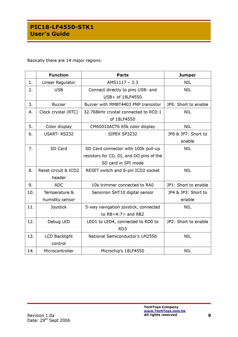
Basically there are 14 major regions: Function Parts Jumper 1. Linear Regulator AMS1117 – 3.3 NIL 2. USB Connect directly to pins USB- and
USB+ of 18LF4550 NIL
3. Buzzer Buzzer with MMBT4403 PNP transistor JP8: Short to enable 4. Clock crystal (RTC) 32.768kHz crystal connected to RC0:1
of 18LF4550 NIL
5. Color display CM60010ACT6 65k color display NIL 6. USART- RS232 SIPEX SP3232 JP6 & JP7: Short to
enable 7. SD Card SD Card connector with 100k pull-up
resistors for CD, DI, and DO pins of the SD card in SPI mode
NIL
8. Reset circuit & ICD2 header
RESET switch and 6-pin ICD2 socket NIL
9. ADC 10k trimmer connected to RA0 JP1: Short to enable 10. Temperature &
humidity sensor Sensirion SHT10 digital sensor JP4 & JP3: Short to
enable 11. Joystick 5-way navigation joystick, connected
to RB<4:7> and RB2 NIL
12. Debug LED LED1 to LED4, connected to RD0 to RD3
JP2: Short to enable
13. LCD Backlight control
National Semiconductor’s LM2556 NIL
14. Microcontroller Microchip’s 18LF4550 NIL

Revision 1.0a Date: 29th Sept 2006
10 TechToys Company www.TechToys.com.hk All rights reserved
PIC18-LF4550-STK1 User’s Guide
3. Software 3.1 Requirement
1. Microchip development MPLAB IDE version 7.41 or above. Download it free from www.microchip.com.
2. C-Compiler for Microchip 18Fxxx series microcontroller. There is a student version of C18 compiler available for download from Microchip’s web site. All applications described in this user’s guide have been developed by C18 version 2.40 under MPLAB IDE version 7.41.

Revision 1.0a Date: 29th Sept 2006
11 TechToys Company www.TechToys.com.hk All rights reserved
PIC18-LF4550-STK1 User’s Guide
4. Example 1 Blink LEDs and Buzzer
We are not giving a PICmicro tutorial. There are many good references available from amazon or Internet for this purpose. Examples listed in this guide have been designed for demonstration purpose only.
Example 1 (source code available from www.TechToys.com.hk → PIC Boards → PIC18-LF4550-STK1 → Software). Copy the project to a convenient place in your development workstation.
1. Plug in 5V DC power or connect a USB cable for power.
2. Plug in ICD2 programming cable to J3
3. Make sure jumpers 8 and jumper 2 shorted for Buzzer and LEDs enable
4. Open example1.mcp from MPLAB. Ctrl+F10 to build all.
5. Click Programmer->Select Programmer->MPLAB ICD2 to make sure ICD2 selected as the programmer
6. Click Programmer->Connect to make sure your ICD2 connects with the board. Note the MPLAB ICD2 messages.

Revision 1.0a Date: 29th Sept 2006
12 TechToys Company www.TechToys.com.hk All rights reserved
PIC18-LF4550-STK1 User’s Guide
7. It is a good time to look at the Vdd level of the board by Programmer → Settings → Power. It should be around 3.30V. Again, please don’t check the Power target circuit from MPLAB ICD 2 (5V Vdd) option.
8. If everything looks alright, click Program from Programmer→Program. After finish, remove the ICD2 cable. Hear the low frequency tone from the buzzer and see LED1-LED4 flashes as expect.

Revision 1.0a Date: 29th Sept 2006
13 TechToys Company www.TechToys.com.hk All rights reserved
PIC18-LF4550-STK1 User’s Guide
The first thing to watch out is the CPU clock speed. A 20MHz crystal is used for OSC1 & OSC2. PIC18F2455/2550/4255/4550 devices include a Phase Locked Loop (PLL) circuit. This is provided specifically for USB applications with lower speed oscillators and can also be used as a microcontroller clock source. Since we are not using the USB module yet, we just skip the PLL part. Let’s look at the source code. It is a simple one.
#include <p18cxxx.h> (1) #include <delays.h> (2) #pragma config FOSC = HS (3) #pragma config CPUDIV = OSC4_PLL6 (4) #pragma config PWRT = ON (5) #pragma config WDT = OFF (6) #pragma config LVP = OFF (7) #pragma config BOR = OFF (8) #pragma config DEBUG = ON (9) #pragma config VREGEN = OFF (10) #pragma config PBADEN = OFF (11) unsigned char counter; void main(void) ADCON1 = 0x0F; (12) TRISCbits.TRISC2 = 0; (13) LATD = 0x00; (14) TRISD = 0x00; (15) while(1) (16) for(counter = 0 ; counter <16; counter++) (17)
LATD = counter; (18) Delay100TCYx(200); (19) LATCbits.LATC2 = !LATCbits.LATC2; (20)
Listing 4-1 Example 1 (blink LEDs and Buzzer)

Revision 1.0a Date: 29th Sept 2006
14 TechToys Company www.TechToys.com.hk All rights reserved
PIC18-LF4550-STK1 User’s Guide
Line (1) specifies the header file to be included for every PICmicro. We don’t need to pay much attention on which PICmicro model to use because it has been taken care of by the Configure->Select Device manual of the MPLAB IDE. Inside p18cxxx.h, there are
#elif defined(__18F4550) #include <p18f4550.h> directives
The correct header file has been included when the program was compiled.
Revision 1.0a Date: 29th Sept 2006
15 TechToys Company www.TechToys.com.hk All rights reserved
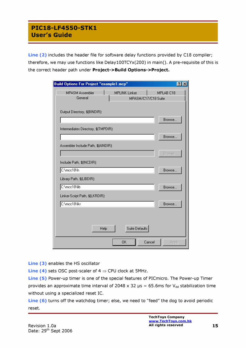
PIC18-LF4550-STK1 User’s Guide Line (2) includes the header file for software delay functions provided by C18 compiler; therefore, we may use functions like Delay100TCYx(200) in main(). A pre-requisite of this is the correct header path under Project->Build Options->Project. Line (3) enables the HS oscillator Line (4) sets OSC post-scaler of 4 ⇒ CPU clock at 5MHz. Line (5) Power-up timer is one of the special features of PICmicro. The Power-up Timer provides an approximate time interval of 2048 x 32 µs = 65.6ms for Vdd stabilization time without using a specialized reset IC. Line (6) turns off the watchdog timer; else, we need to “feed” the dog to avoid periodic reset.

Revision 1.0a Date: 29th Sept 2006
16 TechToys Company www.TechToys.com.hk All rights reserved
PIC18-LF4550-STK1 User’s Guide Line (7) turns off low-voltage programming option, which is not allowed in ICD 2. Line (8) turns off the Brown-out detect feature which simply means ignoring Vdd level for Reset action. A Reset may or may not occur if Vdd falls below VBOR (Brown-out reset voltage). The chip will remain in Brown-out Reset until Vdd rises above VBOR. Line (9) turns on the background debugger option. Line (10) turns off the internal 3.3V regulator since we are not using USB function yet. Line (11) sets PORTB<4:0> as digital IO on Reset. Line (12) sets PORTA for all digital operation.
Line (13) sets RC2 as an output for BUZZER. Make sure the jumper JP8 shorted for BUZZER enable.
Line (14) prepares latch LATD for RD0 – RD3 thus LED1 to LED4 for outputs low (LEDs off to begin). An output high to RD<0:3> will turn on the corresponding LEDs.
Line (15) sets PORTD as an output. Make sure the LED Enable jumper JP2 shorted for visual effect.

Revision 1.0a Date: 29th Sept 2006
17 TechToys Company www.TechToys.com.hk All rights reserved
PIC18-LF4550-STK1 User’s Guide
Line (16) defines an infinite while loop necessary for a C program.
Line (17) – (20) defines a for-loop, flashing the LEDs as a simple counter for a counter value from 0 to 15 (0b00000000 – 0b00001111), software delay for 100*200 machine cycle, and finally toggles the RC2 pin.
Software delay of 100*200 machine cycle ⇒ 20,000*(0.8us)=16ms. Factor of 0.8us because we are running the PICmicro at 5MHz, thus a machine cycle is equal to 4/5MHz (0.8µs). Writing to 18F series port is a little different from 16F series. The port structure is shown below.
• Writing to an I/O port or bit should use LAT register LATCbits.LATC2 = !LATCbits.LATC2; //toggles RC2 pin
• Reading an I/O port or bit uses the PORT register; examples: if (PORTCbits.RC2==1) then “do something” if (PORT==0b11110000) …

Revision 1.0a Date: 29th Sept 2006
18 TechToys Company www.TechToys.com.hk All rights reserved
PIC18-LF4550-STK1 User’s Guide
5. Example 2 USART Communication
This example makes use of the hardware USART library built-in C18 compiler. Download the source code from www.TechToys.com.hk and follow the same procedure as example 1 to download the program. Don’t forget to short jumpers JP6 and JP7 to enable RS232 function, and connect a straight COM PORT cable from J4 to your PC’s COM PORT.

Revision 1.0a Date: 29th Sept 2006
19 TechToys Company www.TechToys.com.hk All rights reserved
PIC18-LF4550-STK1 User’s Guide
Use your favorite RS232 monitoring program to monitor the COM PORT. Adjust the baud rate to be 4800bps. Here I am using Docklight to show the result. This program can be downloaded for free from www.Docklight.de. This is a very good RS232 monitoring program with simple transmit and receive sequence definition.
This example transmits a null terminated string “Communication at 4800 bps: \n” upon system reset. Then it just listens for any character and echoes it back with a “Hello World Echo: “ string as shown below. The source code is heavily commented so I am not going too much on it here.
Revision 1.0a Date: 29th Sept 2006
20 TechToys Company www.TechToys.com.hk All rights reserved
PIC18-LF4550-STK1 User’s Guide
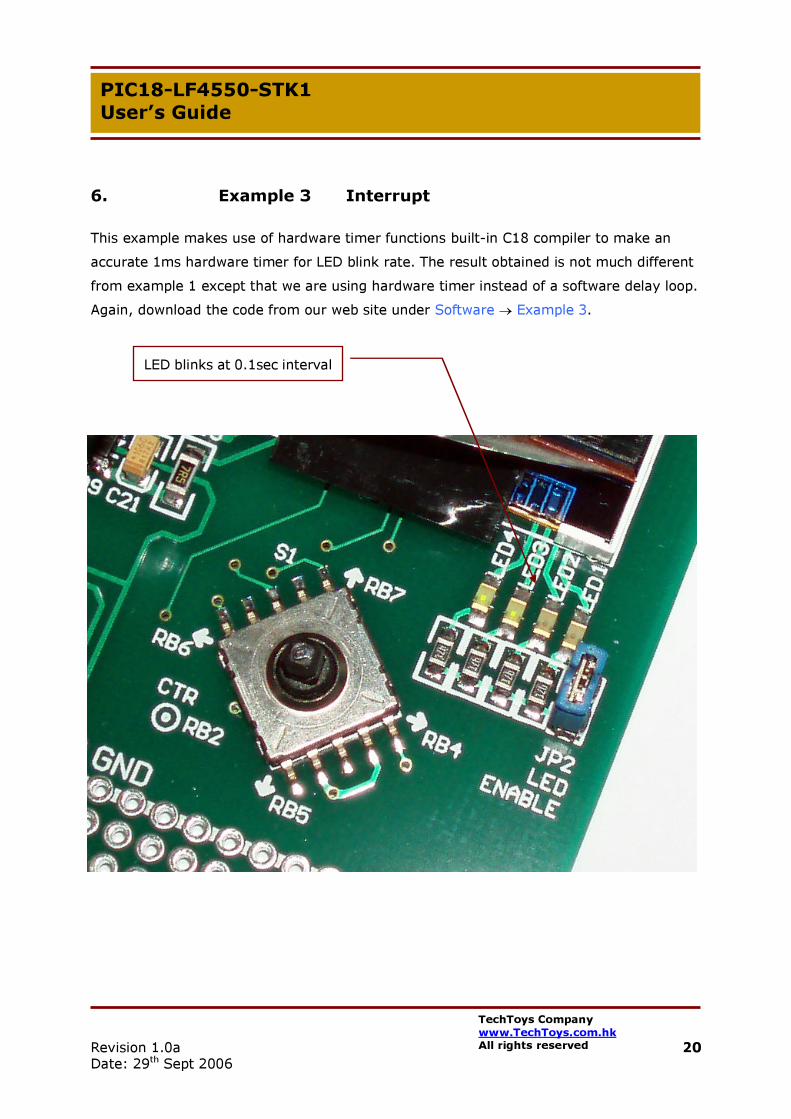
6. Example 3 Interrupt
This example makes use of hardware timer functions built-in C18 compiler to make an accurate 1ms hardware timer for LED blink rate. The result obtained is not much different from example 1 except that we are using hardware timer instead of a software delay loop. Again, download the code from our web site under Software → Example 3.
LED blinks at 0.1sec interval

Revision 1.0a Date: 29th Sept 2006
21 TechToys Company www.TechToys.com.hk All rights reserved
PIC18-LF4550-STK1 User’s Guide
7. Example 4 USB Connection
Here comes an important element of PIC18LF4550: USB connection. PIC18-LF4550-STK1 is compatible with PICDEM FS USB Board of Microchip, in the sense that it is possible to use the Microchip USB Firmware Framework on our board. Refer to the internet resource provided by Microchip at http://www.microchip.com/stellent/idcplg?IdcService=SS_GET_PAGE&nodeId=1406&dDocName=en021940&part=DM163025
The PC-based software, PICDEM FS USB Demo Tool serves as the host application to communicate with our board. This software consists of the Microchip General Purpose USB Windows driver, mchpusb.sys, which allows a PC application to communicate directly to the device’s endpoints.
First, download the MCHPFSUSB Setup file from the internet link above. Unzip to MCHPFSUSB_Setup.EXE. Double click to install. Accept the default installation directory at C:\MCHPFSUSB.

Revision 1.0a Date: 29th Sept 2006
22 TechToys Company www.TechToys.com.hk All rights reserved
PIC18-LF4550-STK1 User’s Guide
After installation, there will be a C:\MCHPFSUSB directory, under which there are fw folder containing all firmware and the folder Pc containing the MCHPUSB Driver and Windows application.
Launch MPLAB, browse to C:\MCHPFUSB\fw\Boot\MCHPUSB.mcp and click open.
Revision 1.0a Date: 29th Sept 2006
23 TechToys Company www.TechToys.com.hk All rights reserved
PIC18-LF4550-STK1 User’s Guide
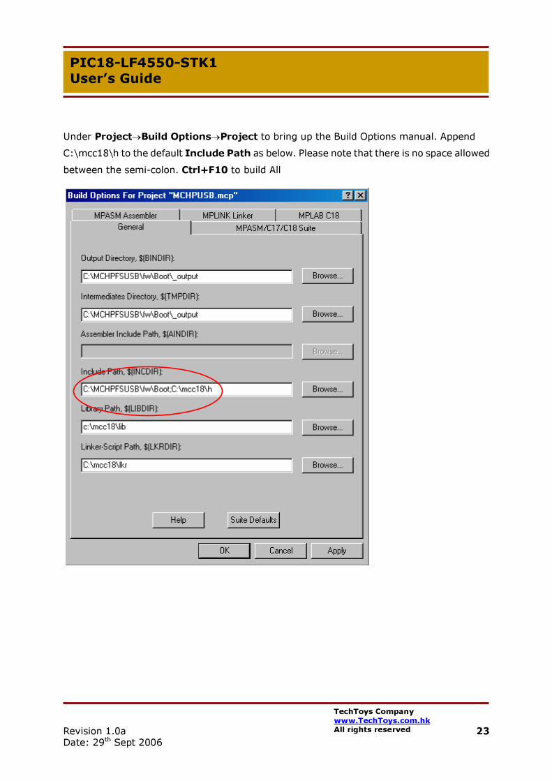
Under Project→Build Options→Project to bring up the Build Options manual. Append C:\mcc18\h to the default Include Path as below. Please note that there is no space allowed between the semi-colon. Ctrl+F10 to build All

Revision 1.0a Date: 29th Sept 2006
24 TechToys Company www.TechToys.com.hk All rights reserved
PIC18-LF4550-STK1 User’s Guide
Make sure jumper JP5 is open. Don’t short the EXT Vdd to Vusb jumper yet. Download the resultant hex code via ICD2. After download, remove the ICD2 cable. While leaving the USB cable connected to the board, pull the joystick to the right and hold, and press reset. Pulling the joystick to the right has the same effect as a single key press connected to RB4. Holding RB4 low when reset key pressed brings PIC18LF4550 to Bootloader mode.
Most likely the PC will be asking for a Windows driver now. Browse to C:\MCHPFSUSB\PC\MCHPUSB Driver\Release. At the “Driver Installation” dialog, confirm that the wizard has located the file mchpusb.inf. Click Next and Finish finally. By that time, your system will have the following device under the Device Manager. This shows successful installation of the Microchip USB driver and successful code download to the board for Bootloader program.

Revision 1.0a Date: 29th Sept 2006
25 TechToys Company www.TechToys.com.hk All rights reserved
PIC18-LF4550-STK1 User’s Guide
To confirm the operation, first make sure LED1 and LED2 are flashing. Launch the Demo Tool application by clicking the “PDFSUSB.exe” icon.
Under Bootload Mode, click on PICDEM FS USB 0 (Boot) tab.
Load HEX File and browse to C:\MCHPFSUSB\fw\_factory_hex\picdemfsusb.hex and click Open.
Revision 1.0a Date: 29th Sept 2006
26 TechToys Company www.TechToys.com.hk All rights reserved
PIC18-LF4550-STK1 User’s Guide
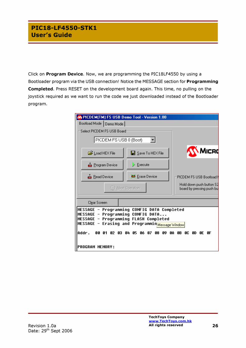
Click on Program Device. Now, we are programming the PIC18LF4550 by using a Bootloader program via the USB connection! Notice the MESSAGE section for Programming Completed. Press RESET on the development board again. This time, no pulling on the joystick required as we want to run the code we just downloaded instead of the Bootloader program.
Revision 1.0a Date: 29th Sept 2006
27 TechToys Company www.TechToys.com.hk All rights reserved
PIC18-LF4550-STK1 User’s Guide
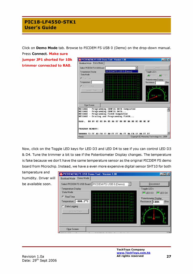
Click on Demo Mode tab. Browse to PICDEM FS USB 0 (Demo) on the drop-down manual. Press Connect. Make sure jumper JP1 shorted for 10k trimmer connected to RA0.
Now, click on the Toggle LED keys for LED D3 and LED D4 to see if you can control LED D3 & D4. Tune the trimmer a bit to see if the Potentiometer Display changes. The temperature is fake because we don’t have the same temperature sensor as the original PICDEM FS demo board from Microchip. Instead, we have a even more expensive digital sensor SHT10 for both temperature and humidity. Driver will be available soon.

Revision 1.0a Date: 29th Sept 2006
28 TechToys Company www.TechToys.com.hk All rights reserved
PIC18-LF4550-STK1 User’s Guide
Try those demonstration programs under cdc & hid folders by using the same download procedure via Bootloader mode. The HID example is a circle mouse example, and the cdc example emulates a COM PORT via USB port.
It is a good time to look at the hardware. Applications provided by PICDEM FS USB have been designed for 18F4550 powered at 5.0V. Is it possible to run under a nominal voltage of 3.3V as we do? There are on-chip features for USB operation including
• USB transceiver • USB voltage regulator • USB pull-up resistors
What they exactly mean is that, there is a regulator built-in the chip that provides 3.3V for the internal USB transceiver, and this transceiver allows a direct connection to the USB cable. Below please find an extract of the 18Fxx5x data sheet for reference.

Revision 1.0a Date: 29th Sept 2006
29 TechToys Company www.TechToys.com.hk All rights reserved
PIC18-LF4550-STK1 User’s Guide
Take a look at the USB peripheral block diagram. Configuration bit VREGEN takes control on the 3.3V regulator built-in the chip. This internal regulator is enabled by default. If we are using the internal regulator in Vdd=3.3V environment, VUSB would not be able to reach 3.3V. With JP5 open, measure the voltage at Vusb gives us a value of 3.28V (not bad), but this value varies from chip to chip. Experiment shows that, even though we are running at Vdd=3.3V, VUSB voltage is always higher than 3.0V. Connection with USB module remains successful.
If you want to stick to the specification closely, disable the internal regulator and short jumper JP5. This action will path external Vdd to VUSB instead of using the internal 3.3V regulator.
Remark: Remember to disable the internal 3.3V regulator before putting a jumper at JP5.

Revision 1.0a Date: 29th Sept 2006
30 TechToys Company www.TechToys.com.hk All rights reserved
PIC18-LF4550-STK1 User’s Guide
Other important configuration bits are FSEN, UPUEN, and UTRDIS:
• The FSEN bit (UCFG<2>) controls the transceiver speed; setting the bit enables full speed operation
• The on-chip USB pull-up resistors are controlled by the UPEN bit (UCFG<4>) • The UTRDIS bit (UCFG<3>) controls the transceiver, it is enabled by default so the
USB module is enabled by default.
Demonstration programs provided by PICDEM FS USB has configured the UCFG register for full-speed USB 2.0 interface with internal pull-up on D+ signal line. Please refer to the source code for details.

Revision 1.0a Date: 29th Sept 2006
31 TechToys Company www.TechToys.com.hk All rights reserved
PIC18-LF4550-STK1 User’s Guide
8. Example 5 USB Mass Storage
In contrast to the original hardware described in the Microchip’s Application Note AN1003 on USB Mass Storage Device (MSD), a PIC18LF4550 has been employed for our development board. There are three major reasons of this change:
1. SD cards operate in the voltage range of 2.7 to 3.6V 2. The color LCD CM60010ACT6 operates in the voltage range of 3.0 to 3.3V 3. Other active components such as the digital temperature and humidity sensor
(SHT10) operate well in the range of 2.4-5.5V supply voltage
On the original PICDEM FS USB board, a 18F4550 PICmicro is used which requires 5V as the Vdd voltage. Signal level translators MC74VHCT125A are used on PICtail Board for SD to convert 5V to 3.3V and vice versa. It is because a SD Card interfaces with the microcontroller in SPI mode which requires only 4 pins (CS, DO, DI, and SCLK), using a signal level translator seems a natural decision as PIC18LF4450 is a little bit more expensive (and more difficult to source as well) comparing with PIC18F4550. The difficulty with PIC18-LF4550-STK1 is that, besides the SD Card, there is the color LCD module which also requires Vdd to be less than 3.3V. Since the LCD allows microcontroller interface in parallel mode (for memory-mapped operation or discrete IO operation), there are 8 pins for data bus plus 6 pins for control signal, altogether 14 pins! That seems too many for a signal level translator, unless we are willing to pay more for two extra translators and build a more complex PCB board. Finally it comes to a final decision of using PIC18LF4550 and we use the same SPI port to interface the SD Card. On next page please find an extract of schematic for your reference. This schematic is directly compatible with PICtail Board SD thus we may just use the same MSD firmware as described in AN1003. Interested parties may refer to the web site http://www.microchip.com/stellent/idcplg?IdcService=SS_GET_PAGE&nodeId=1824&appnote=en024394 for details.

Revision 1.0a Date: 29th Sept 2006
32 TechToys Company www.TechToys.com.hk All rights reserved
PIC18-LF4550-STK1 User’s Guide
De-coupling capacitors of 0.1uF ceramic and 10uF Tantalum have been placed close to Vdd of the SD Card socket. Resistors of 100k Ohm pull-up to the signal lines CS(chip select), DI (MISO), and DO(MOSI). Card insert (CI) pin wired to RB4 with 10k pull-up. This pin goes low when a SD card inserted to the socket, and WP is the write-protected pin. WP pin wired to RA4, and it goes low when Write-Protect is unlocked (that means RA4 low when the SD card is writable).
Revision 1.0a Date: 29th Sept 2006
33 TechToys Company www.TechToys.com.hk All rights reserved
PIC18-LF4550-STK1 User’s Guide
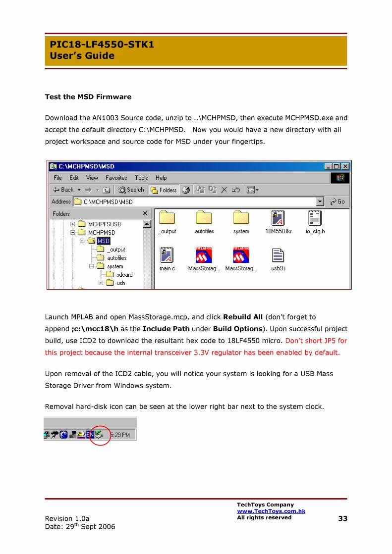
Test the MSD Firmware
Download the AN1003 Source code, unzip to ..\MCHPMSD, then execute MCHPMSD.exe and accept the default directory C:\MCHPMSD. Now you would have a new directory with all project workspace and source code for MSD under your fingertips.
Launch MPLAB and open MassStorage.mcp, and click Rebuild All (don’t forget to append ;c:\mcc18\h as the Include Path under Build Options). Upon successful project build, use ICD2 to download the resultant hex code to 18LF4550 micro. Don’t short JP5 for this project because the internal transceiver 3.3V regulator has been enabled by default.
Upon removal of the ICD2 cable, you will notice your system is looking for a USB Mass Storage Driver from Windows system.
Removal hard-disk icon can be seen at the lower right bar next to the system clock.

Revision 1.0a Date: 29th Sept 2006
34 TechToys Company www.TechToys.com.hk All rights reserved
PIC18-LF4550-STK1 User’s Guide
New Disk drives Microchip Mass Storage USB Device found under the Device Manager.
Most importantly, there is a new drive in the system (Drive F: in my system).
Tests have been performed with a 64MB SanDisk on 4 PCs running Windows XP SP2, and one PC running Windows 2000 SP4 (my flagship workstation). All show successful operation. However, please limit the amount of files on the SD card. A newly formatted card on the development board itself shows a stable result instead of having the card formatted somewhere else.

Revision 1.0a Date: 29th Sept 2006
35 TechToys Company www.TechToys.com.hk All rights reserved
PIC18-LF4550-STK1 User’s Guide
Here shows a screen shoot of my workstation (Windows 2000 SP4). The Microchip USB Mass Storage Device has been assigned a letter F:. The card has been formatted as FAT16. Files on the card are jpeg files, txt file, MS WORD file, and bmp files. Operations like file open, pre-view(under Windows XP), close, and delete all work alright.
It is not the end of the story. What we want to do is to use the color LCD for browsing pictures on the SD Card and create a simple, handy picture viewer. That will be the topic of future application notes.

Revision 1.0a Date: 29th Sept 2006
36 TechToys Company www.TechToys.com.hk All rights reserved
PIC18-LF4550-STK1 User’s Guide
9. Example 6 Color LCD Operation
In the past, only monochrome LCD was included in our development boards, for example, on AT89S52-gLCD-STK1 (www.TechToys.com.hk→8051 Boards) a 128x64 matrix blue text on white screen graphical LCD built-in the board.
On PIC18-LF4550-STK1, because of a higher pin-count, and more Flash/Ram space of the PICmicro, it is possible to include a color display like the 65k color LCD module described in this section. Picture on the right side shows an actual screen-shoot of the color display. System font of an 8-dot height has also been included and displayed. Specification of the color display is available from our web site at http://www.techtoys.com.hk/Components/CM60010ACT6/CM60010ACT6.htm. The module shown on the web site includes a break-out board for 2.00mm pins making it easier for prototyping; whereas the LCD module on the development board has been soldered directly onboard. It is not easy to take it out for other projects. If you want more LCD modules, please consider buying a bare module (part number CM60010ACT6), or CM60010ACT6_BO for a handy module with 2.00mm pins and backlight control circuit.
Here come the hardware details of the color display. CM60010ACT6 is a CSTN color display of 128*3*160 matrix. We put the matrix size like that because there are RGB dots for red, green, and blue color. Dots are physically separated. Individual blue, green, and red dots can be seen under a magnifying glass. Turning all blue dots on will turn the screen blue. Similarly, turning all B, G, and R dots ON will show a white screen. The principle is similar to water color.

Revision 1.0a Date: 29th Sept 2006
37 TechToys Company www.TechToys.com.hk All rights reserved
PIC18-LF4550-STK1 User’s Guide
Features of LCD are summarized as follows:
• Controller: Samsung S6B33BC(COG) • Display mode: CSTN/Negative/Transmissive • Operating voltage: 10V(LCD); 3.0V(VDD) • Interface input data: 8-bit parallel • Driving method: 1/162 Duty, 1/5 Bias • Viewing direction: 6:00 O’clock • Operating temperature: -20˚C ~ 70˚C • Storage temperature: -30˚C ~ 80˚C • LCD module size: 33.54(w) x 45(h) x 1.65Max(t) • Viewing area: 30.54Min(w) x 36.04Min(h) • Effective display area: 27.252(w) x 34.068(h) • Number of dots: 384 (128*3) x 160 dots • Dot size: 0.201(BGR)(w) x 0.201(h) • Dot pitch: 0.213(w) x 0.213(h)
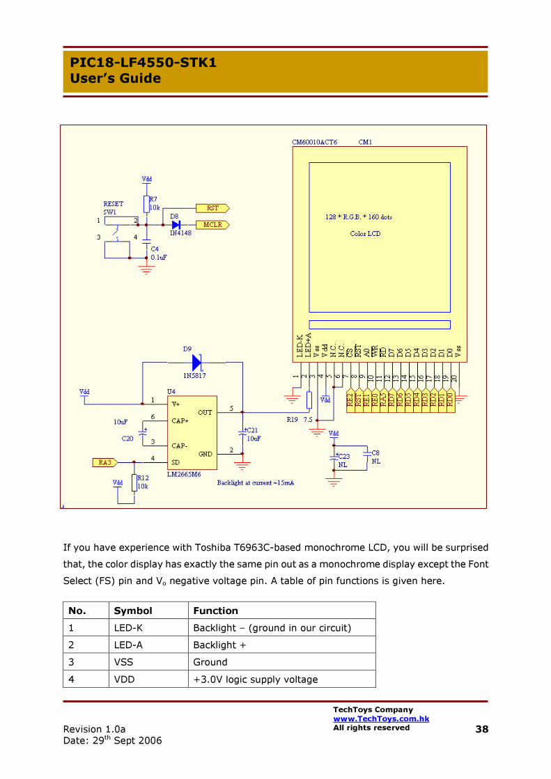
For embedded engineers, the most important information is the schematic describing the LCD interface to the microcontroller, and secondly the command for initialization, contrast setting, and display data read/write, etc. Let’s look at the hardware first. The schematic is illustrated on next page.
Revision 1.0a Date: 29th Sept 2006
38 TechToys Company www.TechToys.com.hk All rights reserved
PIC18-LF4550-STK1 User’s Guide
If you have experience with Toshiba T6963C-based monochrome LCD, you will be surprised that, the color display has exactly the same pin out as a monochrome display except the Font Select (FS) pin and Vo negative voltage pin. A table of pin functions is given here.
No. Symbol Function 1 LED-K Backlight – (ground in our circuit) 2 LED-A Backlight + 3 VSS Ground 4 VDD +3.0V logic supply voltage

Revision 1.0a Date: 29th Sept 2006
39 TechToys Company www.TechToys.com.hk All rights reserved
PIC18-LF4550-STK1 User’s Guide
5 NC No connection 6 NC No connection 7 /CS Chip select, low active 8 /RST Hardware reset, low active
Register select input pin 9 RS –OR- A0 H: display data L: control data
10 /WRB Write enable, low active 11 /RDB Read enable, low active 12-19 D7-D0 8080 8-bit parallel data I/O 20 VSS Ground On contrary to a T6963C-based LCD, there is no Vo or CX pin for -3.5V LCD contrast voltage. The LCD voltage (Vee) is generated internally with registers controlling the voltage level thus making digital contrast control possible. No Font Select pin because there is no internal character set in the LCD controller S6B33BC, therefore no font to select! Instead of an inductor-based DC/DC generator, a simple voltage doubler from National Semiconductor LM2556 has been employed for converting 3.3V to 6.6V for the LED backlight. A current limiting resistor of 7.5Ω limits the current to ~15mA. There is a SD pin on LM2556 for ON/OFF control thus saving us an extra MOSFET for backlight switching. Cost of LM2556 is much cheaper than a DC/DC converter! It only costs US$0.25 in my place. Using it with just two capacitors and an 1N5817 diode saves a lot, really.
Next, we need to discuss how the Samsung LCD controller S6B33BC is controlled. Its data sheet can be found under the same web page as stated in the beginning of this chapter. Samsung’s home page can be found at
http://samsung.com/products/semiconductor/DisplayDriverIC/MobileDDI/ColorSTN/S6B33BC/S6B33BC.htm.

Revision 1.0a Date: 29th Sept 2006
40 TechToys Company www.TechToys.com.hk All rights reserved
PIC18-LF4550-STK1 User’s Guide
Major features of the LCD controller is summarized here:
• On-chip display RAM of 132*162*19-bit • Operates a maximum 132*RGB*162 dots LCD panels. We are using 128*RGB*160
out of it. • Gray scale :
Color Depth Red Green Blue 65,536 32 64 32 4,096 16 16 16 256 8 8 4
• 8-bit / 16-bit parallel bi-directional interface with 8080-series microprocessor • ¾ pin SPI for write only operation (not for us, because we are using 8-bit mode) • On-chip electronic contrast control in 256 steps, that means we can control the
contrast via software • Operating voltage range from 3.0V to 3.3V. Pin 4 of the LCD module CM60010ACT6 is
wired directly to VDD3 of S6B33BC. There are Voltage Converter, Voltage Regulator, and Voltage Follower on-chip thus the necessary LCD operating voltages are all generated inside the chip

Revision 1.0a Date: 29th Sept 2006
41 TechToys Company www.TechToys.com.hk All rights reserved
PIC18-LF4550-STK1 User’s Guide
Control matters
Data is written to or read from the LCD via the eight data lines D0 to D7 (RD0 to RD7). Three control lines D/I (A0), /CS, /RD, and /WR signals are used to control the LCD module. The timing characteristics for the setting of the data and control lines are documented in the data sheet.
Critical data such as tAS80, tPWL80(W) is not available at the time of writing this guide. This may not cause too much problem for us because PICmicro uses a discrete I/O manner for control. The execution time for each command takes one MIP (0.25µs) for a 16MHz CPU clock. This is equivalent to 250ns, and this should be enough for data set-up time, pulse width high/low for write/read, etc.
Note: I have tried running the mcu PIC18LF4550 at Vdd=3.3V, PLL clock frequency at 48MHz. The LCD display still worked even though the specification of the PICmicro restricts the CPU clock at 16MHz at 3.3V. At 48MHz, the display ran very fast, indeed.

Revision 1.0a Date: 29th Sept 2006
42 TechToys Company www.TechToys.com.hk All rights reserved
PIC18-LF4550-STK1 User’s Guide
First-of-all, we need to learn how to write command/data to the module. There is a MPU Interface Protocol in the data sheet as below.
If we translate the diagram to C-programming syntax, we may use the followings. Here I am using a PIC18 series, C18 compiler version 2.40.
void cDispWrDat(INT8U dat) //Data Write cDISP_A0 = HIGH; //A0 HIGH for data, A0 is equivalent to D/I cDISP_CS = LOW; //chip select, low active cDISP_DATA = dat; //prepare data port (PORT D) for data cDISP_WR = LOW; //strobe /WR line low for write action cDISP_WR = HIGH; cDISP_CS = HIGH; //de-select the chip

Revision 1.0a Date: 29th Sept 2006
43 TechToys Company www.TechToys.com.hk All rights reserved
PIC18-LF4550-STK1 User’s Guide
Similarly, command writing may be constructed as follow:
Basically, these two functions cDispWrDat() and cDispWrCmd() compose all examples included in our package. There is no status read and data read in the current version.
The current version of out driver in C18 is version 1.0a. It can be downloaded under our web site at http://www.techtoys.com.hk/Components/CM60010ACT6/CM60010ACT6.htm.
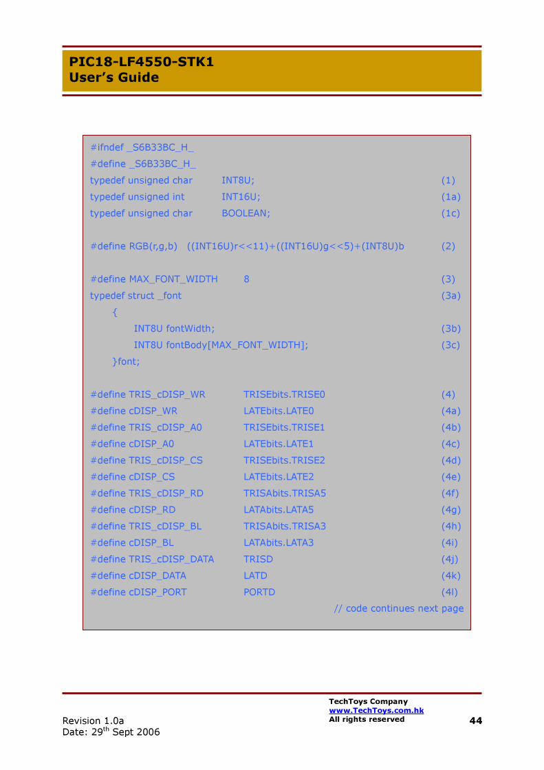
The header file s6b33bc.h is listed in the next page.
void cDispWrCmd(INT8U cmd) //Command Write cDISP_A0 = LOW; //A0 LOW for command, A0 is equivalent to D/I cDISP_CS = LOW; //chip select, low active cDISP_DATA = cmd; //prepare data port (PORT D) for command cDISP_WR = LOW; //strobe /WR line low for write action cDISP_WR = HIGH; cDISP_CS = HIGH; //de-select the chip
Revision 1.0a Date: 29th Sept 2006
44 TechToys Company www.TechToys.com.hk All rights reserved
PIC18-LF4550-STK1 User’s Guide
#ifndef _S6B33BC_H_ #define _S6B33BC_H_ typedef unsigned char INT8U; (1) typedef unsigned int INT16U; (1a) typedef unsigned char BOOLEAN; (1c) #define RGB(r,g,b) ((INT16U)r<<11)+((INT16U)g<<5)+(INT8U)b (2) #define MAX_FONT_WIDTH 8 (3) typedef struct _font (3a) INT8U fontWidth; (3b) INT8U fontBody[MAX_FONT_WIDTH]; (3c) font; #define TRIS_cDISP_WR TRISEbits.TRISE0 (4) #define cDISP_WR LATEbits.LATE0 (4a) #define TRIS_cDISP_A0 TRISEbits.TRISE1 (4b) #define cDISP_A0 LATEbits.LATE1 (4c) #define TRIS_cDISP_CS TRISEbits.TRISE2 (4d) #define cDISP_CS LATEbits.LATE2 (4e) #define TRIS_cDISP_RD TRISAbits.TRISA5 (4f) #define cDISP_RD LATAbits.LATA5 (4g) #define TRIS_cDISP_BL TRISAbits.TRISA3 (4h) #define cDISP_BL LATAbits.LATA3 (4i) #define TRIS_cDISP_DATA TRISD (4j) #define cDISP_DATA LATD (4k) #define cDISP_PORT PORTD (4l)
// code continues next page
Revision 1.0a Date: 29th Sept 2006
45 TechToys Company www.TechToys.com.hk All rights reserved
PIC18-LF4550-STK1 User’s Guide
Line (1) – (1c) type definition for convenience
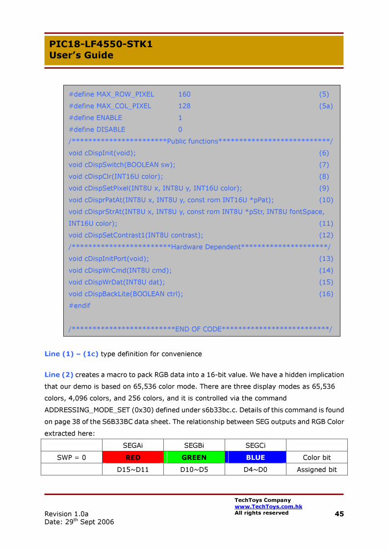
Line (2) creates a macro to pack RGB data into a 16-bit value. We have a hidden implication that our demo is based on 65,536 color mode. There are three display modes as 65,536 colors, 4,096 colors, and 256 colors, and it is controlled via the command ADDRESSING_MODE_SET (0x30) defined under s6b33bc.c. Details of this command is found on page 38 of the S6B33BC data sheet. The relationship between SEG outputs and RGB Color extracted here:
SEGAi SEGBi SEGCi SWP = 0 RED GREEN BLUE Color bit
D15~D11 D10~D5 D4~D0 Assigned bit
#define MAX_ROW_PIXEL 160 (5) #define MAX_COL_PIXEL 128 (5a) #define ENABLE 1 #define DISABLE 0 /***********************Public functions***************************/ void cDispInit(void); (6) void cDispSwitch(BOOLEAN sw); (7) void cDispClr(INT16U color); (8) void cDispSetPixel(INT8U x, INT8U y, INT16U color); (9) void cDisprPatAt(INT8U x, INT8U y, const rom INT16U *pPat); (10) void cDisprStrAt(INT8U x, INT8U y, const rom INT8U *pStr, INT8U fontSpace, INT16U color); (11) void cDispSetContrast1(INT8U contrast); (12) /************************Hardware Dependent*********************/ void cDispInitPort(void); (13) void cDispWrCmd(INT8U cmd); (14) void cDispWrDat(INT8U dat); (15) void cDispBackLite(BOOLEAN ctrl); (16) #endif /*************************END OF CODE**************************/
Revision 1.0a Date: 29th Sept 2006
46 TechToys Company www.TechToys.com.hk All rights reserved
PIC18-LF4550-STK1 User’s Guide
Line (3) - (3c) defines a font structure same as that used in another monochrome KS0108-based graphical LCD. There is a detailed description on this under the link http://www.techtoys.com.hk/8051/AT89S52-gLCD-STK1/AT89S52-gLCD-STK1.htm so I am not repeating here. However, I must say a font width of only 8 pixels may not be enough for a display of pixel size 0.213*0.213mm. Bigger font size work-under-progress.
Line (4) – (4l) defines the connection between PICmicro and LCD display. Modification required if you use different hardware.
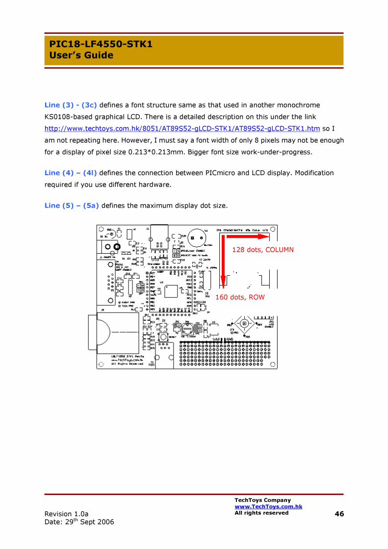
Line (5) – (5a) defines the maximum display dot size.
128 dots, COLUMN
160 dots, ROW

Revision 1.0a Date: 29th Sept 2006
47 TechToys Company www.TechToys.com.hk All rights reserved
PIC18-LF4550-STK1 User’s Guide
Line (6) is the initialization function for S6B33BC chip. This function should be called before any other functions. Refer to s6b33bc.c for details of this function. I hereby describe a few of the key parameters which need modification if you are going to use the display in different settings and orientation. An extract of cDispInit(void):
Line (6_2) is a software delay function included in C18 package. Delay10KTCYx(8) delays for 20ms required by the Power On Sequence (page 67 on S6B33BC). Change this function to any delay function you like, as long as it is a 20ms delay.
Line (6_3) – (6_4) worth a longer story here. These two lines configure the display direction. Driver Output Mode Set (10h) is an important instruction. It determines the scanning direction of pixel writing. The SDIR flag of Driver Output Mode Set instruction selects the direction of segment display. The direction of common scanning is selected by CDIR bit.
void cDispInit(void) …
cDispWrCmd(STANDBY_MODE_OFF); (6_1) Delay10KTCYx(8); (6_2)
… cDispWrCmd(DRIVER_OUTPUT_MODE_SET); (6_3) cDispWrCmd(0x25); (6_4) … cDispSetContrast1(0x60); (6_5) … cDispWrCmd(ADDRESSING_MODE_SET); (6_6)
cDispWrCmd(0x1C); (6_7) … cDispClr(RGB(31,63,31)); (6_8)
cDispWrCmd(DISPLAY_ON); (6_9)

Revision 1.0a Date: 29th Sept 2006
48 TechToys Company www.TechToys.com.hk All rights reserved
PIC18-LF4550-STK1 User’s Guide
An extract from S6B33BC data sheet, page 30 is shown below.
RS (D/I) WRB RDB DB7 DB6 DB5 DB4 DB3 DB2 DB1 DB0 0 0 0 1 0 0 0 0 0 0 1 0 0 DLN 0 SDIR SWP CDR
A value of 0x25 in Driver Output Mode sets SDIR=1 & CDR=1. The impact is that we have a start scanning point at the top left hand corner of the display when we are viewing it in the frontal up direction matching the PCB layout.
The question is, what if we want to set the start scan point from the lower right corner? We may change the parameter from 0x25 -> 0x20 as follows:
cDispWrCmd(DRIVER_OUTPUT_MODE_SET);
cDispWrCmd(0x20); //write a command of 0x20 instead of 0x25
SDIR=1 to scan from SEG=131 to 4, i.e. for 128 dots
CDIR=1 to scan from COM=161 to 2 for 160 dots
Y-address counter 131 ~ 4
X-address counter 161 ~ 2

Revision 1.0a Date: 29th Sept 2006
49 TechToys Company www.TechToys.com.hk All rights reserved
PIC18-LF4550-STK1 User’s Guide
Line (6_5) sets the contrast in the normal mode. A value of 0x60 sets V1 to be 2.753V, good for us at Vdd=3.3V. This may be changed for a different viewing angle or different Vdd.
Information on page 36 of the data sheet.
Line (6_6) – (6_7) set the color mode; in this case, we are doing it for 65,536 color.
Line (6_8) performs a repeat pixel write to all 128*64 dots of the whole screen at pure white color.
Line (6_9) turns the display ON. Nothing can be seen until this line. It is an interesting experiment to see what happen if we are swapping the sequence of line 6_8 and line 6_9.
Now we go back to S6B33BC.h:
Line (7) switches the display ON/OFF. The flag to use is ENABLE/DISABLE. RAM content preserved by this function. Line (8) clears the display by a single color. It can be
white - RGB(31,63,31) Red - RGB(31,0,0) Green - RGB(0,63,0) Blue - RGB(0,0,31) OR any color combination in a 16-bit value
Example: cDispClr(RGB(0,50,0)); Line (9) sets a single pixel at a position x, y with a 16-bit color value. Definition of the coordinates system is shown on the right.
(0,0)
(127,159)

Revision 1.0a Date: 29th Sept 2006
50 TechToys Company www.TechToys.com.hk All rights reserved
PIC18-LF4550-STK1 User’s Guide
Line (10) displays a picture in form of an array defined in the rom space. Line (11) displays a string from the rom space with variable spacing between each character. Line (12) sets the contrast of the display.
Please refer to the source code for further details as it is heavily commented. Bear in mind that there are a lot of features of the LCD display not included in the current version such as display scrolling, read mode, color palette function, and color mode switching.

Revision 1.0a Date: 29th Sept 2006
51 TechToys Company www.TechToys.com.hk All rights reserved
PIC18-LF4550-STK1 User’s Guide
void main(void) INT8U i; ADCON1 = 0x0F; (1) cDispInit(); (2) cDispBackLite(ENABLE); (3) for(;;) cDispClr(RGB(31,0,0)); (4) cDispSetPixel(0, 0, RGB(31,63,31)); (5) cDispSetPixel(0, 159, RGB(31,63,31)); (6) cDispSetPixel(127, 0, RGB(31,63,31)); (7) cDispSetPixel(127, 159, RGB(31,63,31)); (8)
cDisprStrAt(32, 32, "ABCDFEFHIJKLMN…..67890abcdefghijklmnopq", 1, RGB(0,63,0)); (9)
for(i=0;i<10;i++) Delay10KTCYx(100); (10) cDispClr(RGB(0,63,0)); (11) cDisprStrAt(32, 32, "ABCDFEFH…RST1234567890", 1, RGB(31,0,0)); (12) for(i=0;i<10;i++) Delay10KTCYx(100); cDispClr(RGB(0,0,31)); (13)
cDisprStrAt(32, 32, “ABCDFEFHIJKLMN…rtuy567567", 1, RGB(10,45,0)); (14) for(i=0;i<10;i++) Delay10KTCYx(100); cDispClr(RGB(31,63,31)); (15)
cDisprStrAt(32, 32, "ABCDF..Y3465756[];;'.<>", 1, RGB(0,0,0)); (16) for(i=0;i<10;i++) Delay10KTCYx(100); cDisprPatAt(20,64, &golden[0]); (17) for(i=0;i<10;i++) Delay10KTCYx(100);
It is a good time to look at the actual demonstration program. Please refer to the full source code in Demo 1: Color Graphical LCD driver (Samsung S6B33BC) in C18 ver1.0a under our web site at http://www.techtoys.com.hk/PIC_boards/PIC18-4455-STK1/pic18-4550-stk1.htm.

Revision 1.0a Date: 29th Sept 2006
52 TechToys Company www.TechToys.com.hk All rights reserved
PIC18-LF4550-STK1 User’s Guide
This is the result after line (1) ~ (9). Random text written with automatic text wrap at the right margin. Green text on red background, with four white dots at each corner to make sure the function cDispSetPixel() works as expected.
Same method as above, red text on green background this time.
Green text on blue background. The result is not as bad as this as seen under naked eyes. This result is a direct consequence of digital camera photography on a dot-matrix LCD.

Revision 1.0a Date: 29th Sept 2006
53 TechToys Company www.TechToys.com.hk All rights reserved
PIC18-LF4550-STK1 User’s Guide
- END -
Finally, black text on white background, then with a small picture of my puppy on screen. This puppy became a 31kg Golden Retriever now!