Embed Size (px)
Citation preview

Insight Vol 48 No 3 March 2006 155
C Nageswaran, C R Bird and R Takahashi
Based on a paper presented at NDT 2005, the 44th Annual British Conference on NDT, Harrogate, UK, September 2005.
1. Introduction
1.1 Background
This paper results from work carried out on the CRAFT Framework V project NANOSCAN (G4ST-CT-2002-5028). The aim of the project was to study the effectiveness of several current NDT techniques for the inspection of aerospace composites. The techniques evaluated include air-coupled ultrasonics, thermography, shearography and resonance testing. The materials of primary concern were CFRP laminates and honeycomb structures. A range of defect types can degrade the quality of both these composite materials and it was the aim of each technique to both detect and classify these defects.
1.2 Carbon fibre reinforced plastics and the critical defects
The manufacturing process (hand lay-up) can lead to several flaws: 1.Foreignbodyinclusions(backingfilm,dust). 2. Voids (entrapped air, moisture ingress). 3.Incorrectlay-uporder(fibre/plymisalignment). 4. Incorrectly applied curing cycle. 5. Bonding failure between plies during cure.
In-service damage primarily leads to delaminations that could arise from voids and inclusions introduced during fabrication (but missed by QA procedures) which then act as initiator sites once the component becomes a load-bearing structure. Another major form of damage is induced by relatively low velocity impacts on the component (dropping tools on the wing skin, bird strike on aircraft during flight). These events lead to extensive subsurface delaminations without any obvious visual clues on the impacted surface; this is often referred to in industry parlance as Barely Visible Impact Damage (BVID).
1.3 Phased array (PA) equipment
From their initial NDT applications in the nuclear industry, phased arraytechniquesarebeingconsideredforuseindifferentfieldsand
the NANOSCAN project evaluated the use of PA technology for composites in the aerospace sector.
The R/D Tech FOCUS 32/128 PA system was used in thisproject. It is able to build an active aperture using a maximum of 32 elements and address 128 channels. The Tomoview (Version 2.2 Release 9) data collection software was used for data representation and analysis.
2. Experiments
2.1 Specimens
All the specimens in this project are based on the aerospace grade prepregs(‘pre-impregnated’continuousfibresinresin)AS4/8552andHTS/6376manufacturedtoaerospacespecifications(HS-CP-5000)(1).TheAS4(12Kfibrecount/tow)wasinfusedinapart-curedepoxy matrix to derive the 8552 system; it is tough in resisting impacts and is highly damage-tolerant. It is amine cured to increase the toughness of the epoxy resin and to operate in temperatures of up to 121°C. Table 1 summarises the specimen details.
2.2 Defects
Three types of defects were investigated ultrasonically in this project.Duringhand lay-upof thespecimen,Teflon insertsweredeliberatelyinsertedbetweenplies.Theseareknowntoartificiallysimulate inter-ply delamination and are also representative of manufacturing inclusions type of defect. The acoustic impedance mismatchbetweenthebulkCFRPandtheTeflonshouldleadtotheirdetection. The N-series panels are manufactured with entrapped air; this leads to the introduction of gross porosity where there is impedance mismatch between the material and air. Impact-induced damage is known to lead to severe delamination below the impact surface. The panels are scanned after the introduction of impacts rangingfrom30 to70Joules introducedasdescribedbelow.Wenotedthatonan8mm(64plies)thickquasi-isotropicpanel45Jrepresented the threshold for initiation and perforation took place around 60 J (Figure 1). However, as noted in the literature, thethreshold values are dependent on many factors and researchers have found a very large variation(2, 3).
Impact damage was introduced to the Q-ID specimen using theRosand InstrumentedFallingWeight ImpactTester (IFWIT).
INSPECTION OF AEROSPACE COMPOSITES
Phased array scanning of artificial and impact damage in carbon fibre reinforced plastic (CFRP)
Carbon Fibre Reinforced Plastic (CFRP) materials are increasingly being used in modern civilian aircraft for structural applications. There is an urgent need to detect and classify delamination defects and evaluate the threat to the integrity of the component in-service. This paper presents a study to evaluate the use of ultrasonic phased array (PA) technology for this purpose.
Linear array ultrasonic probes are used to scan CFRP panels that contain both Teflon simulated delaminations and Barely Visible Impact Damage (BVID) caused by drop weight impacting. The advantages and disadvantages of using PA technology for thin composite material components are discussed.
Channa Nageswaran, Colin R Bird and Reiko Takahashi are with TWI Ltd, Granta Park, Great Abington, Cambridge, CB1 6AL, UK. Tel: 01223 891 162, Ext. 2548; E-mail: [email protected]
Code Material Lay-up Length (mm)
Width (mm)
Thickness (mm)
Defect Type
Q-ID-2 AS4/8552 QI 220 210 8 I
Q-ID-60 AS4/8552 QI 210 110 8 I
N1-D HTS/6376 UD 280 90 4 A/P
N2-D HTS/6376 CP 280 90 4 A/P
N3-D HTS/6376 QI 280 90 4 A/P
N4-D HTS/6376 UD 280 100 1 A/P
Table 1. Specimen details and lay-up
(Key: QI – Quasi-isotropic; UD – Unidirectional; CP – Cross-ply; A – Artificial delaminations; I – Impact damage; P – Flawed cure cycle induced porosity).

156 Insight Vol 48 No 3 March 2006
Energy of impact was controlled by changing the height of the drop weight (potential to kinetic energy). The specimen was rigidly supported on a rectangular window of 100 mm x 110 mm; the impactorheadwas20mmindiameterandweighed4.72kg.Afterseveral trials, 3 mm-thick neoprene padding was placed over the impact point to prevent surface damage; the neoprene would have absorbed some of the impacting energy and hence the imparted energy was less than that calculated. Since the aim was to study the characteristics of the impact damage rather than the conditions and mechanisms by which it took place, this discrepancy is not expected to be an issue.
A number of specimens were destructively evaluated to measure and confirm the presence of impact-induced and porosity defects. The length of delaminations and their through-thickness positions, as measured using micrographs, were compared to ultrasonic evaluations (both PA and conventional).
A diamond saw was used to section specimens and subsequently polished to a 0.25 mm finish and mounted in CitoFix. A digital optical microscope is used for imaging (x1000 maximum magnification).
2.3 Probes
CIVA(4) and Quicksonic(5) modelling software are used to theoreticallychecktheintegrityoftheincidentPAsoundfieldandremove unexpected grating lobes. An example of using CIVA is given in Figure 2 for the probe used in collecting the data presented inthispaper(7MHz,16-elementaperture,0.6mmpitch).
2.4 Scanning
All the data presented in this paper were collected in pulse echo mode (both conventional and PA) because more information can be derived about the through-thickness features of the material (as opposed to through-transmission). Furthermore, in-service inspections of aircraft components may allow one-sided access only and the scanning frames required for pulse echo testing are less complicated and more adaptable. Noting that delaminations occur between plies and are always parallel to the surface, 0° incidence testing offers the best inspection strategy (in terms of defectdetectionandcouplingefficiency).
An important aspect of the present work is the need to immerse the specimens. When several elements of an array are phased,time delays are applied to focus the resultant sound beam within adesired zone (inour case at 0° incidenceon to the specimen).The number of elements (hence the active aperture) determines the distance required in the medium for effective beam forming to take place (Figure 2). A practical value for the minimum focal range distanceisgivenasfollows:
........................................(1)
WhereB is the distance in medium, A is the active aperture length and λ is the wavelength in the medium. CFRP specimens are too thin to allow beam forming (1 to 8 mm); furthermore, the
anisotropic properties (highly dependent on lay-up) re-distribute the sound energy unfavourably. Hence, to use a linear array in a phased configuration, the specimen must be immersed in water so that the beam can be effectively formed for inspection.
The need for immersion is noted to be a disadvantage in both post-manufacture and in-service inspection as components could be susceptible to damage by moisture ingress.
3. Results and discussion
3.1 Material characteristics
For the current study, an accurate value for the longitudinal velocity ofthesoundinthematerialwasmeasuredtobe2850m/swithastandard deviation of 1.3%. Similarly, the attenuation (combined absorption and scattering) of the beam through the material was measured as a function of sample thickness and frequency; this then allows us to choose an appropriate frequency for the study.
3.2 Artificial delaminations
For aircraft in-service, the maximum allowable defect size(especially delamination) before it is considered to be beyond airworthinessdependsonseveralfactors:q Designphilosophy(Failsafe/Safelife).qMaterialtype.qImpactriskzones(droppedtools,maintenancetraffic,runway
debris etc).Similarly, the criteria relating to monolithic components
is different to sandwich components due to differing damage morphology(6).A typicalcriticaldelaminationsize inCFRPwingskin exposed to direct airflow is 10 mm x 10 mm for a modern fighteraircraft.The-6dBdropmethodisusedforsizing(7) where a locuslinetracinga6dBdropintheamplitudefromthemaximumvalueoverthedefectrepresentsthedefectsize.
Figure 3 shows a scan of the N1-D specimen. It shows the presence of the artificial delamination and the presence of through-thickness gross porosity. The PA system is able to impose the -6dBsizingcriterion forboth thedelaminationand theporosityregions automatically. The through-thickness positions can also be evaluated accurately.
3.3 Manufacture-induced porosity
A study of the morphology of porosity in three different lay-ups shows that the weave of the material plays an important role in the degree of damage. Figure 4 shows C-scans of N2-D and N3-D that are of cross-ply and quasi-isotropic lay-up, respectively. All the panels have flawed cure cycle induced porosity. Three
Figure 1. Damage size related to energy of impact under present set-up scenario
Figure 2. 16-element linear aperture with 0.6 mm pitch; calculated field in water for point focusing without significant grating lobes
Insight Vol 48 No 3 March 2006 157
equal volumes of ultrasonic data are extracted for the three lay-up specimens of 1.4 x 180 x 100 mm3.
The maximum echo amplitude within this volume above 20% of the front wall echo was plotted on a two-dimensional map; hence, the area of the total cross-section covered by porosity is evaluated by image thresholding (Figure 5). The total volume of porous region is greatest in the cross-ply panel, then the quasi-isotropic and least in the unidirectional laminate; furthermore, the fibres tend to ‘guide’ the growth direction. Porosity is created due to entrapped air between the fibres and can be used to deduce the lay-up of a laminate(8).
The porosity levels in the unidirectional, cross-ply and quasi-isotropiclaminatesare6.94%,19.83%and10.33%,respectively.
Figure 3. 32-element linear array scan of N1-D showing artificial delamination and gross porosity (B-scan to the left, C-scan on the right)
Figure 4. Entrapped porosity in three lay-up schemes
Figure 5. A two-dimensional map of the porosity damage for unidirectional (top), cross-ply and quasi-isotropic laminates
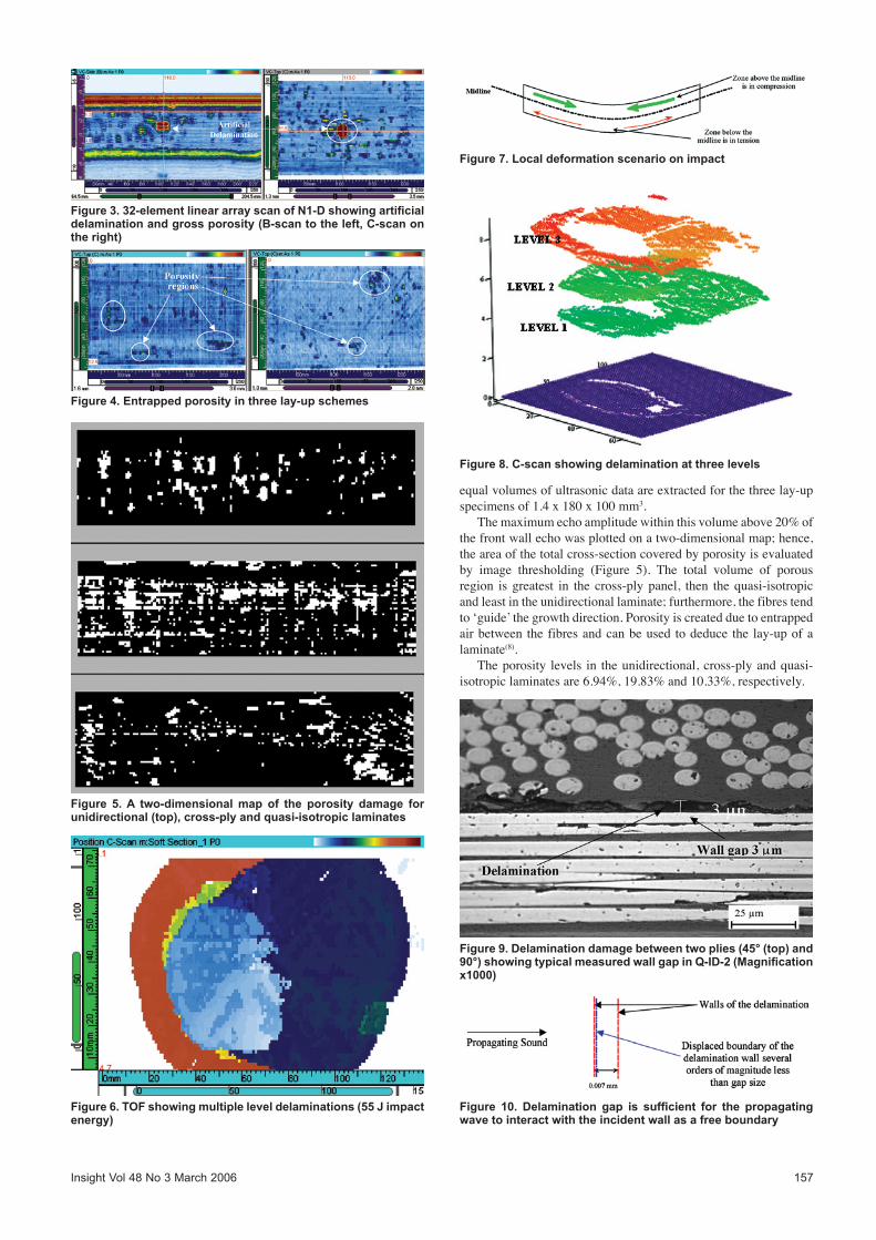
Figure 6. TOF showing multiple level delaminations (55 J impact energy)
Figure 7. Local deformation scenario on impact
Figure 8. C-scan showing delamination at three levels
Figure 9. Delamination damage between two plies (45° (top) and 90°) showing typical measured wall gap in Q-ID-2 (Magnification x1000)
Figure 10. Delamination gap is sufficient for the propagating wave to interact with the incident wall as a free boundary
158 Insight Vol 48 No 3 March 2006
3.4 Impact-induced delaminations
Itwasconfirmed that impactdamageexistsatdifferent levelsofthrough-thickness;thisisdonebyatime-of-flight(TOF)analysis(Figure6).
The delamination near the back wall is larger than the ones near thefrontwall(wheretheimpacttookplace).Whenimpactedthereisrapidlocalbendingattheimpactpoint(Figure7).
The in-plane shear stresses created between successive plies in different orientations leads to a break down in the bonding, creating delamination; the mismatch in bending stiffness has been directly related to the severity(9). It is also possible to deduce the major orientationdirections(0°,+/-45°,90°).
Figure 8 shows a PA amplitude scan. RF data was collected at adigitisingfrequencyof100MHz.Theprobewasa16-element7MHzlinearprobe.Gatescanbeusedtoselectsignalsatdifferentlevels. The data file was modified to remove repeat echoes that result in a misleading picture of the damage inside the material and artificially extend delaminations; currently there is no algorithm in the software to perform this task and hence repeat echoes were manually identified and deleted.
A studywas carried out to confirm the 6 dB drop ultrasonicsizingofthedelaminationsinthesamplebysectioning.Athrough-thickness datum plane was identified accurately and corrected depth and size measurements were made of the delaminations.The sample was then sectioned and micrographs were taken at magnificationsfromx16tox1000(forexampleFigure9)
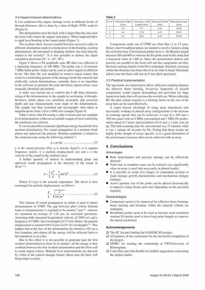
Table2showsthatPAtestingisabletolocateandsizemultiplelevel delaminations within an acceptable margin of error (satisfying theminimumsizecriteria).
It was not possible to transmit significant energy beyond the first incident delamination. For sound propagation in a medium (both planar and spherical) the particle vibration amplitude is related to the sound pressure using the following relation(11):
........................................(2)
p is the sound pressure (Pa); ρ is density (kg/m3); ω is angular frequency (rad/s), ξ is particle displacement (m) and c is the velocityofthesoundinthemedium(m/s).
A further quantity of interest in understanding plane and spherical sound propagation is the intensity of the sound in W/m2 (11):
................................(3)
WhereZ (=ρc) is the acoustic impedance. The above is then rearrangedforparticledisplacement,asfollows:
....................................(4)
This feature of sound propagation in solids is used to detect delaminations in CFRP. The gap between plies (where disbond leadstodelaminations)isreportedtobearound7mm(10), whereas we measured an average of 3.24 mm on sectioned specimens. Assumingbulkmeasuredlongitudinalvelocityof2850m/sandafrequencyof5MHz,thewavelengthis0.57mm.Hence,theparticledisplacement is around 0.00114 mm (2x10⁻⁶of wavelength)(11). This implies that at the face of the delamination the interface will see a free boundary and almost all the energy will be reflected back to the transducer as an echo.
Due to this effect it is not possible to penetrate past the first incident delamination to those in its shadow; all the energy is then confined between the first incident delamination and the front wall tocreaterepeatechoes.Multipleleveldelaminationsaredetectedby virtue of the conical damage feature (those near the back wall being larger in area).
Components made out of CFRP are often thin (1 to 15 mm). Hence, short broadband pulses are needed to resolve features along the axial direction. Conventional probes have a –20 dB pulse length between 200 and 800 ns whereas the PA probe used in this study had a measured value of 1300 ns. Since the delamination defects and porosity are parallel to the front wall and the components are thin, the beam steering feature of the PA is redundant. Similarly, focusing within the thickness has been shown to do little to better illuminate defects near the back wall (for an 8 mm-thick specimen).
3.5 Practical implementation
Thespecimensareimmersedtoallowsufficientcouplingdistancefor effective beam forming. In-service inspection of aircraft components would require dismantling and provision for large immersiontanksthatwillincreasetheoverallcost.WhencollectingRF,thedatavolumetransferisalimitingfactoronthesizeofthearray that can be used effectively.
A major known advantage of using array transducers (not necessarily working in phased array configuration) is the increase in scanning speeds that can be achieved. A scan of a 100 mm x 100mmpanelwithan8MHzconventionaland7MHzPAprobes,motorspeedof5mm/sandresolutionof0.6mmx1mm,wassetup. The total scanning time for conventional was 33 minutes while itwas1minute46 seconds forPA.Noting that these results arehighly probe (length of array) specific, it is a good illustration of the performance increases that can be achieved with an array.
4. Conclusions
Advantages
n Both delamination and porosity damage can be effectively detected.
nTotaltimetocompletescanscanbereducedverysignificantlywhen an array is used (not necessarily in phased mode).
nIt is possible to create live images of component sections to study damage growth characteristics and mechanisms (fatigue loading).
nActiveaperturesizeoftheprobecanbealteredelectronicallytoimprovesizing(beamspotsize)dependingontheprecisionrequired.
Disadvantages
nComponent needs to be immersed for effective beam forming; beam steering and focusing within the material volume are redundant.
nBroadband probes need to be used to increase axial resolution (current PA probes tend to have long pulse lengths to improve the lateral resolution).
Acknowledgements
q The EC for part funding the NANOSCAN project.qAll partners of the consortium for the successful completion of
the project. qEPSRC for funding the studentship at TWI/University of
Birmingham.qColinBirdandJohnRudlinforhelpfulsuggestionsconcerning
the subject matter.
Level UltrasonicDepth(mm)
Ultrasonic-6dBLength (mm)
MeasuredDepth(mm)
MeasuredLength(mm)
1 2.5 9.2 2.61 10.052 4.4 27.8 4.51 28.433 6.2 68.2 6.33 69.56
Table 2
Insight Vol 48 No 3 March 2006 159
References and footnotes
1. Hexcel, Prepreg Datasheets, www.hexcel.com2. S Abrate, ‘Impact on laminated composite materials’, Appl.
Mech.Rev.,Vol44,No4,pp155-190,1991.3. P Robinson and G A O Davies, ‘Impactor mass and specimen
geometry effects in low velocity impact of laminated composites’, Int J Impact Eng., Vol 12, No 2, pp 189-207,1992.
4. CEA,CIVA:SimulationsoftwareforNonDestructiveTesting,www-civa.cea.fr, France.
5. Imasonic, Quicksonic v 4.01, www.imasonic.com, France.6. MMS 13, ‘Assessment & Criticality of Defects & Damage
in Materials Systems – Task 1 Review’, www.mms15.com,2003.
7. RASmith,‘Ultrasonicdefectsizingincarbonfibrecomposites–aninitialstudy’,Insight,Vol36,No8,1994.
8. RASmithandBClarke,‘UltrasonicC-scandeterminationofply stacking sequence in carbon-fibre composites’, Insight,Vol36,No10,1994.
9. D Liu, ‘Impact induced delamination – a view of bending stiffnessmismatching’,JCompos.Mater.,Vol22,pp674-692,1988.
10. P A Lagace, ‘On delamination failures in composite laminates’, Composite Structures:Testing,Analysis andDesign,NarosaPublishing House, pp 111-132, New Delhi, 1992.
11.J Krautkramer and H Krautkramer, ‘Ultrasonic Testing ofMaterials’,Springer-Verlag,1990.
Copyright 2005,TWILtd.
Enquiry No 603-10
Cost-effective advertising
Insight is essential reading for all practitioners, engineers and scientists in the areas of NDT
and Condition Monitoring. And, amalgamationof the previous British and European Journalsof Non-Destructive Testing into Insight andthe resulting quarterly European issues, hasresulted in a wider readership in Europe.
With low cost advertising options and excellent editorial, Insight offers the marketer an attractive
opportunity to penetrate these vital sectors.With its high pass-on readership, each issue is seen
by as many as 10,000 decision-makers.
Advertising your product or service in this space could cost as little as £160*
Telephone David Gilbert on 01604 630124 for further details.
*Rate per quarter-page mono insertion for contract of 12. Subject to VAT