Embed Size (px)
Citation preview
Conformal phased array aero-opticalmodeling and compensation
Matthew R. WhiteleyStanislav Gordeyev
Conformal phased array aero-optical modeling andcompensation
Matthew R. WhiteleyMZA Associates Corporation1360 Technology Ct., Suite 200Dayton, Ohio 45430E-mail: [email protected]
Stanislav GordeyevUniversity of Notre DameInstitute for Flow Physics and ControlIndiana, 46556
Abstract. The effect of subsonic turbulent boundary layer aero-optical dis-turbances on a conformal phased array for laser beam projection operat-ing on a high-speed aircraft is considered. We employ a basic model forsubsonic boundary layer disturbances developed by Cress et al. which isgoverned by the displacement thickness δ� to bound the magnitude of theproblem, to determine the basic phenomenology affecting phased arrayperformance, and to quantify requirements for compensation of these dis-turbances in the array subapertures. We used δ� ¼ 15 mm as a baselinevalue in quantifying phased array effects on a 7-aperture hexagonal arraywith 10 cm subapertures. Boundary layer piston and tilt disturbancesdominate array effects, but higher-order disturbances are similar in mag-nitude to the differential piston over the array and 2× greater in magnitudethan an upper bound on free-stream turbulence. Adaptive optics compen-sation of turbulent boundary layer disturbances in such a phased arrayrequires error rejection bandwidths >1 kHz for high-fidelity array perfor-mance. © 2013 Society of Photo-Optical Instrumentation Engineers (SPIE) [DOI: 10.1117/1.OE.52.7.071409]
Subject terms: aero-optics; phased array; boundary layer; wavefront error; adaptiveoptics.
Paper 121577SS received Oct. 29, 2012; revised manuscript received Jan. 25,2013; accepted for publication Jan. 25, 2013; published online Feb. 28, 2013.
1 IntroductionThis study addresses the effect of aero-optical disturbancesfor conformal aperture systems on high-speed aircraft. Theseoptical systems are designed to blend with the outer mouldline of the aircraft, and therefore would experience less deg-radation due to aero-optical disturbances compared to a con-ventional hemisphere-on-cylinder turret. The most likelycandidates for such a conformal optical system would bea phased array architecture, where the effective projectionor imaging aperture for the optical system is comprised ofa collection of array elements or subapertures. In order togain the full benefit of the distribution of apertures overthe airframe, the phasing of these apertures must be main-tained within a fraction of the operating wavelength.
While a conformal aperture system will not experiencethe extreme degradation typical of a laser turret configura-tion,1 the optical system will however be subject to turbulentboundary layer disturbances2 which develop over the skin ofany aircraft system. Turbulent boundary layers arise asthe air flow will have a velocity profile ranging from 0near the aircraft surface to the free-stream velocity u∞ adistance away from the surface beyond the limit of theboundary layer. The boundary layer thickness is typicallyquantified as the point at which the surface-layer velocityis 0.99u∞. However, a more useful metric for quantifyingturbulent boundary layer effects is the displacement thick-ness δ�, which is computed from the density profile ρðyÞand velocity profile uðyÞ for a given free-stream air densityρ∞ as
δ� ¼Z
∞
0
�1 −
ρðyÞuðyÞρ∞u∞
�dy: (1)
At low speed the velocity profile will be laminar, but asspeed increases the flow within the boundary layer willbecome turbulent. The Reynolds number Re is typicallyused to quantify the degree to which a turbulent conditionexists, and is calculated as
Re ¼ ρ∞u∞x∕μ∞; (2)
where μ∞ is the free-stream viscosity of air and x is a down-stream location on the aircraft. Given the Reynolds num-ber, the displacement thickness for a downstream locationrelative to the tip of the aircraft is computed as
δ� ¼ 0.0463 xRe−0.2: (3)
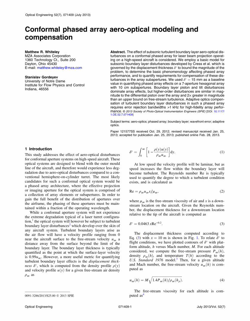
The displacement thickness computed according toEq. (3) with x ¼ 10 m is shown in Fig. 1. To relate δ� toflight conditions, we have plotted contours of δ� with plat-form altitude, h versus Mach number, M. For each altitudeconsidered, we compute the free-stream pressure P∞ðhÞ,density ρ∞ðhÞ, and temperature TðhÞ according to theU.S. Standard 1976 model.3 Then, for a given altitudeand Mach number, the free-stream velocity u∞ðhÞ is com-puted as
u∞ðhÞ ¼ Mffiffiffiffiffiffiffiffiffiffiffiffiffiffiffiffiffiffiffiffiffiffiffiffiffiffiffiffiffiffiffiffiffiffiffiffi1.4P∞ðhÞ∕ρ∞ðhpÞ
q: (4)
The free-stream viscosity for each altitude is com-puted as40091-3286/2013/$25.00 © 2013 SPIE
Optical Engineering 071409-1 July 2013/Vol. 52(7)
Optical Engineering 52(7), 071409 (July 2013)
μ∞ðhÞ ¼ ½1.458 μPa s K−1∕2� TðhÞ3∕2TðhÞ þ 110.3 K
: (5)
Given these quantities, Re is computed according toEq. (2) and used in Eq. (3) for δ�. As the contours ofFig. 1 illustrate, for platform altitudes in the range of 5 to10 km and Mach numbers in the range of 0.5 to 1.0, the inter-val of δ� values is relatively small, ranging from 10 to13 mm. Thus, in this regime variation in the displacementthickness is will be related more to airframe geometrythan atmospheric properties.
The displacement thickness δ� has been shown to be afundamental scaling parameter for the optical properties ofturbulent boundary layers.5 These observations have ledresearchers, primarily Gordeyev et al. at the University ofNotre Dame to develop particular modeling methods for tur-bulent boundary layers which are reviewed in Sec. 2. UsingGordeyev’s basic modeling method, we have applied suchboundary layer aero-optical disturbances to the problem ofconformal aperture arrays in Sec. 3, quantifying the modalstatics over such an array for a range of relevant δ�. Wethen consider the compensation of turbulent boundary layeraero-optical disturbances for a conformal phased array sys-tem, quantifying the temporal properties of these disturb-ances and the bandwidth requirements for adaptive optics(AO) correction of such disturbances in an example array.We draw conclusions in Sec. 5.
2 Turbulent Boundary Layer Aero-OpticalWavefront Modeling
To address the influence of turbulent boundary layer disturb-ances on conformal apertures, we have patterned our workafter the empirical scaling relations developed by Cressand Gordeyev at the University of Notre Dame.2,6 In theirapproach, the random wavefront error associated withsubsonic boundary layer aero-optics with adiabatic wallconditions has been observed to scale as
σBL ¼ 1.65 × 10⁻⁵δ�ðρ∞∕ρSLÞM2; (6)
where ρSL is air density at sea level, M is the free-streamMach number, and δ� is the displacement thickness asdefined in Eq. (1). Equation (6) is valid for propagationperpendicular to the surface, i.e., perpendicular to the turbu-lent boundary layer. When propagating off-normal, it hasbeen shown in other studies7 that Eq. (6) can be extendedconsidering β, the angle between the surface and the propa-gation direction, as in Eq. (7).
σBL ¼ 1.65 × 10⁻⁵δ�ðρ∞∕ρSLÞM2∕ sinðβÞ: (7)
This modification is simply a geometric scaling of thedisplacement thickness as the angle of propagation offperpendicular is increased. Although the precise scalingwith propagation angle is complicated by the anisotropicnature of the boundary layer vortices, empirical studieshave shown these relationship to hold in an approximatesense over a range of test angles.2 The scaling model ofEq. (7) has been recently reexamined in the light of newdata available for supersonic boundary layers, and a modi-fication has been proposed for both subsonic and supersonicboundary layers.5 The work with supersonic boundary layersis preliminary at this time and based on a single supersonicmeasurement. Given the range of flight conditions beingconsidered here, we have elected to use the previouslyreported observations for subsonic boundary layers tostudy conformal array aero-optics.
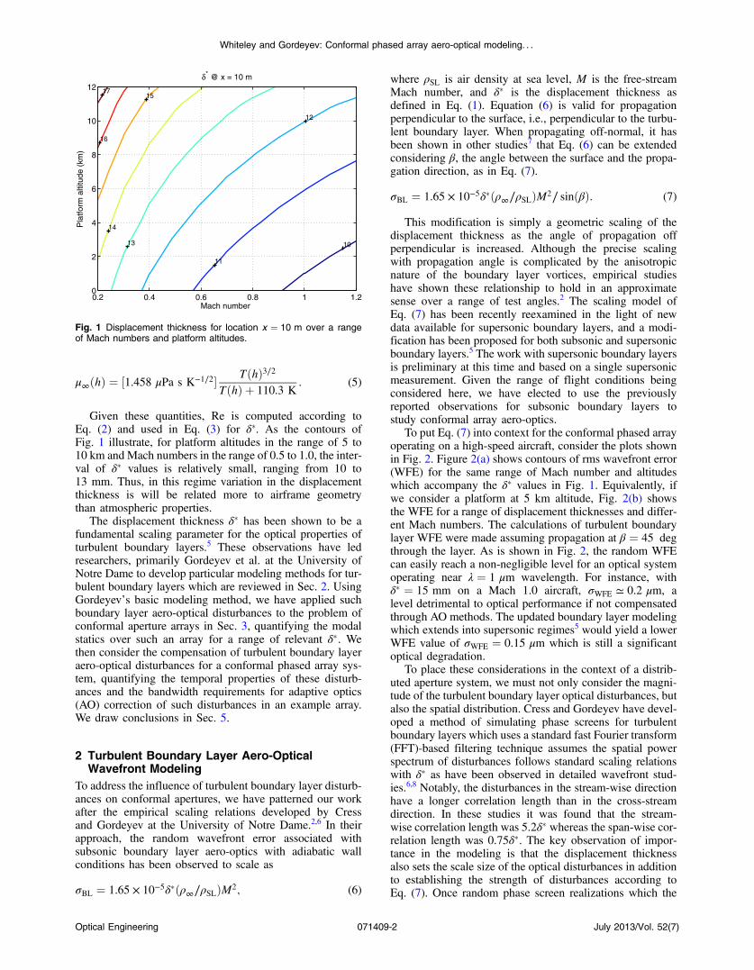
To put Eq. (7) into context for the conformal phased arrayoperating on a high-speed aircraft, consider the plots shownin Fig. 2. Figure 2(a) shows contours of rms wavefront error(WFE) for the same range of Mach number and altitudeswhich accompany the δ� values in Fig. 1. Equivalently, ifwe consider a platform at 5 km altitude, Fig. 2(b) showsthe WFE for a range of displacement thicknesses and differ-ent Mach numbers. The calculations of turbulent boundarylayer WFE were made assuming propagation at β ¼ 45 degthrough the layer. As is shown in Fig. 2, the random WFEcan easily reach a non-negligible level for an optical systemoperating near λ ¼ 1 μm wavelength. For instance, withδ� ¼ 15 mm on a Mach 1.0 aircraft, σWFE ≃ 0.2 μm, alevel detrimental to optical performance if not compensatedthrough AO methods. The updated boundary layer modelingwhich extends into supersonic regimes5 would yield a lowerWFE value of σWFE ¼ 0.15 μm which is still a significantoptical degradation.
To place these considerations in the context of a distrib-uted aperture system, we must not only consider the magni-tude of the turbulent boundary layer optical disturbances, butalso the spatial distribution. Cress and Gordeyev have devel-oped a method of simulating phase screens for turbulentboundary layers which uses a standard fast Fourier transform(FFT)-based filtering technique assumes the spatial powerspectrum of disturbances follows standard scaling relationswith δ� as have been observed in detailed wavefront stud-ies.6,8 Notably, the disturbances in the stream-wise directionhave a longer correlation length than in the cross-streamdirection. In these studies it was found that the stream-wise correlation length was 5.2δ� whereas the span-wise cor-relation length was 0.75δ�. The key observation of impor-tance in the modeling is that the displacement thicknessalso sets the scale size of the optical disturbances in additionto establishing the strength of disturbances according toEq. (7). Once random phase screen realizations which the
10
11
12
13
14
15
16
17
Mach number
Pla
tform
alti
tude
(km
)δ* @ x = 10 m
0.2 0.4 0.6 0.8 1 1.20
2
4
6
8
10
12
Fig. 1 Displacement thickness for location x ¼ 10 m over a rangeof Mach numbers and platform altitudes.
Optical Engineering 071409-2 July 2013/Vol. 52(7)
Whiteley and Gordeyev: Conformal phased array aero-optical modeling. . .
proper power and spatial scale (set by δ�) are generated, thesedisturbances can be used as phase screens in a wave-opticssimulation. To simulate temporal dynamics of the boundarylayer disturbance, the simulated phase screen can be trans-lated at a convention rate which is approximately 0.8u∞,as has been observed in the fundamental measurementssupporting the modeling approach.7
3 Aero-Optical Mode Statistics in a ConformalAperture Array
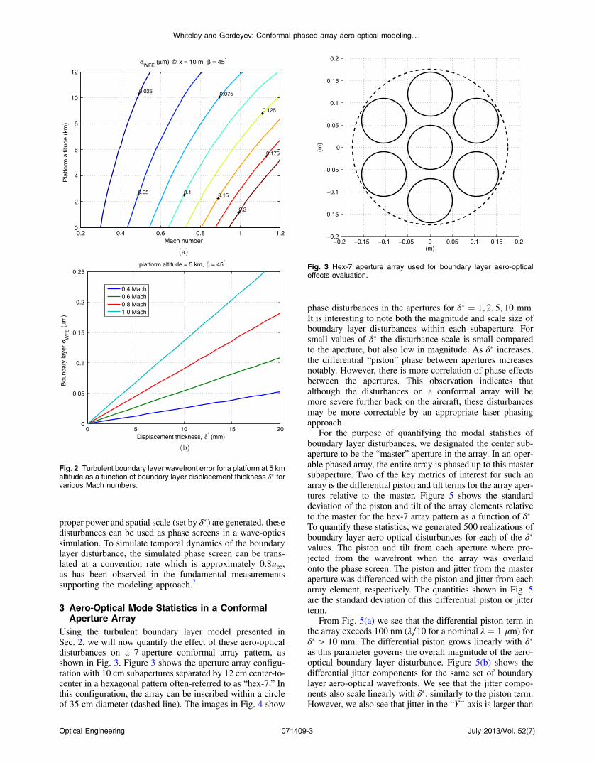
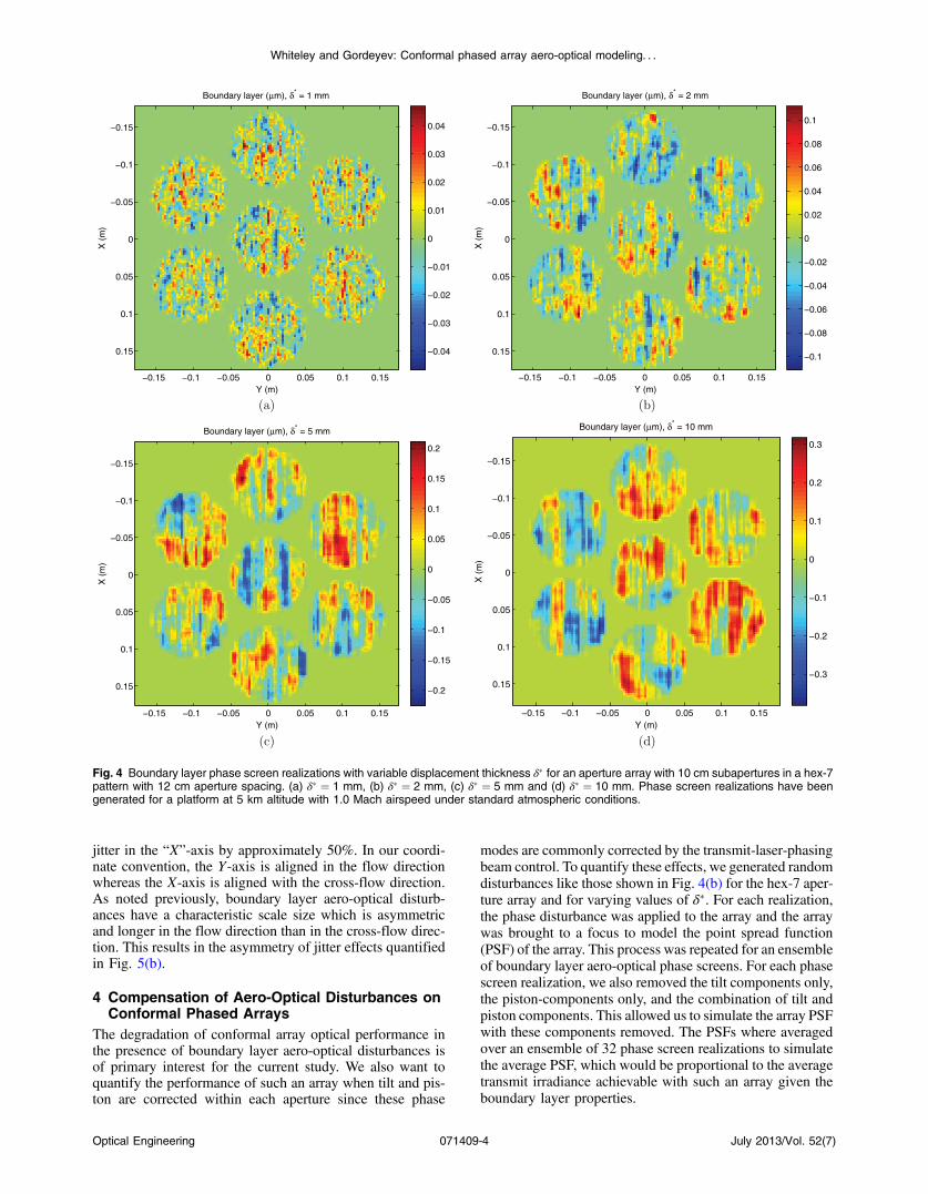
Using the turbulent boundary layer model presented inSec. 2, we will now quantify the effect of these aero-opticaldisturbances on a 7-aperture conformal array pattern, asshown in Fig. 3. Figure 3 shows the aperture array configu-ration with 10 cm subapertures separated by 12 cm center-to-center in a hexagonal pattern often-referred to as “hex-7.” Inthis configuration, the array can be inscribed within a circleof 35 cm diameter (dashed line). The images in Fig. 4 show
phase disturbances in the apertures for δ� ¼ 1; 2; 5; 10 mm.It is interesting to note both the magnitude and scale size ofboundary layer disturbances within each subaperture. Forsmall values of δ� the disturbance scale is small comparedto the aperture, but also low in magnitude. As δ� increases,the differential “piston” phase between apertures increasesnotably. However, there is more correlation of phase effectsbetween the apertures. This observation indicates thatalthough the disturbances on a conformal array will bemore severe further back on the aircraft, these disturbancesmay be more correctable by an appropriate laser phasingapproach.
For the purpose of quantifying the modal statistics ofboundary layer disturbances, we designated the center sub-aperture to be the “master” aperture in the array. In an oper-able phased array, the entire array is phased up to this mastersubaperture. Two of the key metrics of interest for such anarray is the differential piston and tilt terms for the array aper-tures relative to the master. Figure 5 shows the standarddeviation of the piston and tilt of the array elements relativeto the master for the hex-7 array pattern as a function of δ�.To quantify these statistics, we generated 500 realizations ofboundary layer aero-optical disturbances for each of the δ�values. The piston and tilt from each aperture where pro-jected from the wavefront when the array was overlaidonto the phase screen. The piston and jitter from the masteraperture was differenced with the piston and jitter from eacharray element, respectively. The quantities shown in Fig. 5are the standard deviation of this differential piston or jitterterm.
From Fig. 5(a) we see that the differential piston term inthe array exceeds 100 nm (λ∕10 for a nominal λ ¼ 1 μm) forδ� > 10 mm. The differential piston grows linearly with δ�as this parameter governs the overall magnitude of the aero-optical boundary layer disturbance. Figure 5(b) shows thedifferential jitter components for the same set of boundarylayer aero-optical wavefronts. We see that the jitter compo-nents also scale linearly with δ�, similarly to the piston term.However, we also see that jitter in the “Y”-axis is larger than
0.025
0.05
0.075
0.1
0.125
0.15
0.175
0.2
Mach number
Pla
tform
alti
tude
(km
)σ
WFE (µm) @ x = 10 m, β = 45°
0.2 0.4 0.6 0.8 1 1.20
2
4
6
8
10
12
0 5 10 15 200
0.05
0.1
0.15
0.2
0.25
Displacement thickness, δ* (mm)
Bou
ndar
y la
yer
σ WF
E (
µm)
platform altitude = 5 km, β = 45°
0.4 Mach0.6 Mach0.8 Mach1.0 Mach
Fig. 2 Turbulent boundary layer wavefront error for a platform at 5 kmaltitude as a function of boundary layer displacement thickness δ� forvarious Mach numbers.
−0.2 −0.15 −0.1 −0.05 0 0.05 0.1 0.15 0.2−0.2
−0.15
−0.1
−0.05
0
0.05
0.1
0.15
0.2
(m)
(m)
Fig. 3 Hex-7 aperture array used for boundary layer aero-opticaleffects evaluation.
Optical Engineering 071409-3 July 2013/Vol. 52(7)
Whiteley and Gordeyev: Conformal phased array aero-optical modeling. . .
jitter in the “X”-axis by approximately 50%. In our coordi-nate convention, the Y-axis is aligned in the flow directionwhereas the X-axis is aligned with the cross-flow direction.As noted previously, boundary layer aero-optical disturb-ances have a characteristic scale size which is asymmetricand longer in the flow direction than in the cross-flow direc-tion. This results in the asymmetry of jitter effects quantifiedin Fig. 5(b).
4 Compensation of Aero-Optical Disturbances onConformal Phased Arrays
The degradation of conformal array optical performance inthe presence of boundary layer aero-optical disturbances isof primary interest for the current study. We also want toquantify the performance of such an array when tilt and pis-ton are corrected within each aperture since these phase
modes are commonly corrected by the transmit-laser-phasingbeam control. To quantify these effects, we generated randomdisturbances like those shown in Fig. 4(b) for the hex-7 aper-ture array and for varying values of δ�. For each realization,the phase disturbance was applied to the array and the arraywas brought to a focus to model the point spread function(PSF) of the array. This process was repeated for an ensembleof boundary layer aero-optical phase screens. For each phasescreen realization, we also removed the tilt components only,the piston-components only, and the combination of tilt andpiston components. This allowed us to simulate the array PSFwith these components removed. The PSFs where averagedover an ensemble of 32 phase screen realizations to simulatethe average PSF, which would be proportional to the averagetransmit irradiance achievable with such an array given theboundary layer properties.
Y (m)
X (
m)
Boundary layer (µm), δ* = 1 mm
−0.15 −0.1 −0.05 0 0.05 0.1 0.15
−0.15
−0.1
−0.05
0
0.05
0.1
0.15 −0.04
−0.03
−0.02
−0.01
0
0.01
0.02
0.03
0.04
Y (m)
X (
m)
Boundary layer (µm), δ* = 2 mm
−0.15 −0.1 −0.05 0 0.05 0.1 0.15
−0.15
−0.1
−0.05
0
0.05
0.1
0.15−0.1
−0.08
−0.06
−0.04
−0.02
0
0.02
0.04
0.06
0.08
0.1
Y (m)
X (
m)
Boundary layer (µm), δ* = 5 mm
−0.15 −0.1 −0.05 0 0.05 0.1 0.15
−0.15
−0.1
−0.05
0
0.05
0.1
0.15 −0.2
−0.15
−0.1
−0.05
0
0.05
0.1
0.15
0.2
Y (m)
X (
m)
Boundary layer (µm), δ* = 10 mm
−0.15 −0.1 −0.05 0 0.05 0.1 0.15
−0.15
−0.1
−0.05
0
0.05
0.1
0.15−0.3
−0.2
−0.1
0
0.1
0.2
0.3
Fig. 4 Boundary layer phase screen realizations with variable displacement thickness δ� for an aperture array with 10 cm subapertures in a hex-7pattern with 12 cm aperture spacing. (a) δ� ¼ 1 mm, (b) δ� ¼ 2 mm, (c) δ� ¼ 5 mm and (d) δ� ¼ 10 mm. Phase screen realizations have beengenerated for a platform at 5 km altitude with 1.0 Mach airspeed under standard atmospheric conditions.
Optical Engineering 071409-4 July 2013/Vol. 52(7)
Whiteley and Gordeyev: Conformal phased array aero-optical modeling. . .
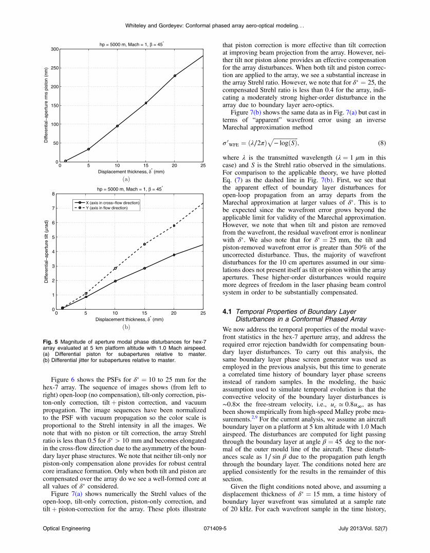
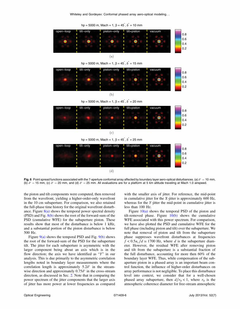
Figure 6 shows the PSFs for δ� ¼ 10 to 25 mm for thehex-7 array. The sequence of images shows (from left toright) open-loop (no compensation), tilt-only correction, pis-ton-only correction, tiltþ piston correction, and vacuumpropagation. The image sequences have been normalizedto the PSF with vacuum propagation so the color scale isproportional to the Strehl intensity in all the images. Wenote that with no piston or tilt correction, the array Strehlratio is less than 0.5 for δ� > 10 mm and becomes elongatedin the cross-flow direction due to the asymmetry of the boun-dary layer phase structures. We note that neither tilt-only norpiston-only compensation alone provides for robust centralcore irradiance formation. Only when both tilt and piston arecompensated over the array do we see a well-formed core atall values of δ� considered.
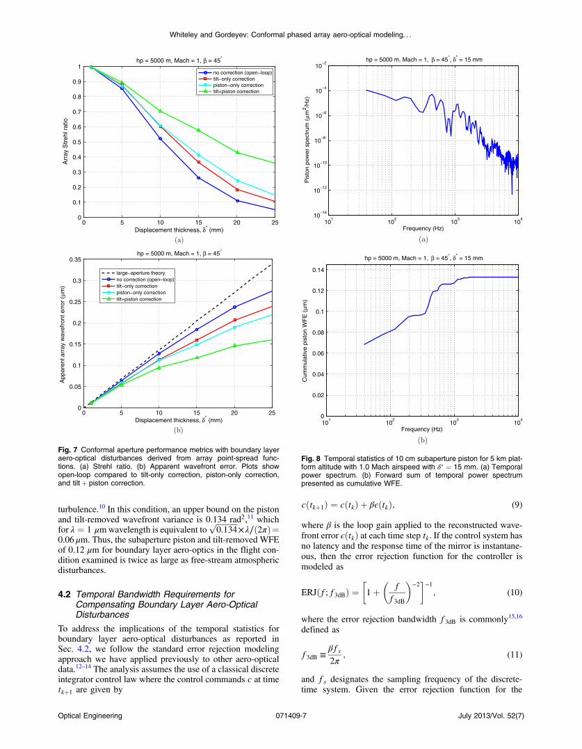
Figure 7(a) shows numerically the Strehl values of theopen-loop, tilt-only correction, piston-only correction, andtiltþ piston-correction for the array. These plots illustrate
that piston correction is more effective than tilt correctionat improving beam projection from the array. However, nei-ther tilt nor piston alone provides an effective compensationfor the array disturbances. When both tilt and piston correc-tion are applied to the array, we see a substantial increase inthe array Strehl ratio. However, we note that for δ� ¼ 25, thecompensated Strehl ratio is less than 0.4 for the array, indi-cating a moderately strong higher-order disturbance in thearray due to boundary layer aero-optics.
Figure 7(b) shows the same data as in Fig. 7(a) but cast interms of “apparent” wavefront error using an inverseMarechal approximation method
σ 0WFE ¼ ðλ∕2πÞ
ffiffiffiffiffiffiffiffiffiffiffiffiffiffiffiffiffi− logðSÞ
p; (8)
where λ is the transmitted wavelength (λ ¼ 1 μm in thiscase) and S is the Strehl ratio observed in the simulations.For comparison to the applicable theory, we have plottedEq. (7) as the dashed line in Fig. 7(b). First, we see thatthe apparent effect of boundary layer disturbances foropen-loop propagation from an array departs from theMarechal approximation at larger values of δ�. This is tobe expected since the wavefront error grows beyond theapplicable limit for validity of the Marechal approximation.However, we note that when tilt and piston are removedfrom the wavefront, the residual wavefront error is nonlinearwith δ�. We also note that for δ� ¼ 25 mm, the tilt andpiston-removed wavefront error is greater than 50% of theuncorrected disturbance. Thus, the majority of wavefrontdisturbances for the 10 cm apertures assumed in our simu-lations does not present itself as tilt or piston within the arrayapertures. These higher-order disturbances would requiremore degrees of freedom in the laser phasing beam controlsystem in order to be substantially compensated.
4.1 Temporal Properties of Boundary LayerDisturbances in a Conformal Phased Array
We now address the temporal properties of the modal wave-front statistics in the hex-7 aperture array, and address therequired error rejection bandwidth for compensating boun-dary layer disturbances. To carry out this analysis, thesame boundary layer phase screen generator was used asemployed in the previous analysis, but this time to generatea correlated time history of boundary layer phase screensinstead of random samples. In the modeling, the basicassumption used to simulate temporal evolution is that theconvective velocity of the boundary layer disturbances is∼0.8× the free-stream velocity, i.e., uc ≃ 0.8u∞, as hasbeen shown empirically from high-speed Malley probe mea-surements.2,9 For the current analysis, we assume an aircraftboundary layer on a platform at 5 km altitude with 1.0 Machairspeed. The disturbances are computed for light passingthrough the boundary layer at angle β ¼ 45 deg to the nor-mal of the outer mould line of the aircraft. These disturb-ances scale as 1∕ sin β due to the propagation path lengththrough the boundary layer. The conditions noted here areapplied consistently for the results in the remainder of thissection.
Given the flight conditions noted above, and assuming adisplacement thickness of δ� ¼ 15 mm, a time history ofboundary layer wavefront was simulated at a sample rateof 20 kHz. For each wavefront sample in the time history,
0 5 10 15 20 250
50
100
150
200
250
300
Displacement thickness, δ* (mm)
Diff
eren
tial−
aper
ture
rm
s pi
ston
(nm
)hp = 5000 m, Mach = 1, β = 45°
0 5 10 15 20 250
1
2
3
4
5
6
7
8
Displacement thickness, δ* (mm)
Diff
eren
tial−
aper
ture
tilt
(µra
d)
hp = 5000 m, Mach = 1, β = 45°
X (axis in cross−flow direction)Y (axis in flow direction)
Fig. 5 Magnitude of aperture modal phase disturbances for hex-7array evaluated at 5 km platform altitude with 1.0 Mach airspeed.(a) Differential piston for subapertures relative to master.(b) Differential jitter for subapertures relative to master.
Optical Engineering 071409-5 July 2013/Vol. 52(7)
Whiteley and Gordeyev: Conformal phased array aero-optical modeling. . .
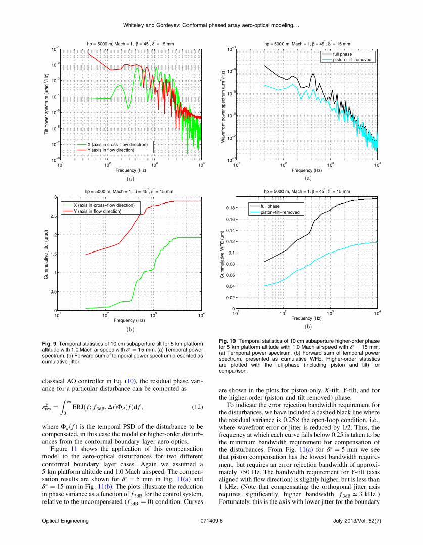
the piston and tilt components were computed, then removedfrom the wavefront, yielding a higher-order-only wavefrontin the 10 cm subaperture. For comparison, we also retainedthe full-phase time history for the original wavefront disturb-ance. Figure 8(a) shows the temporal power spectral density(PSD) and Fig. 8(b) shows the root of the forward-sum of thePSD (cumulative WFE) for the subaperture piston. Theseresults show that most of the disturbance is below 1 kHz,and a substantial portion of the piston disturbance is below500 Hz.
Figure 9(a) shows the temporal PSD and Fig. 9(b) showsthe root of the forward-sum of the PSD for the subaperturetilt. The jitter for each subaperture is asymmetric with thelarger component being about an axis which is in theflow direction; the axis we have identified as “Y” in ouranalysis. This is due primarily to the asymmetric correlationlengths noted in boundary layer measurements where thecorrelation length is approximately 5.2δ� in the stream-wise direction and approximately 0.75δ� in the cross-streamdirection, as discussed in Sec. 2. Note that in comparing thepower spectrum of the jitter components that the larger axisof jitter has more power at lower frequencies as compared
with the smaller axis of jitter. For reference, the mid-pointin cumulative jitter for the X-jitter is approximately 600 Hz,whereas for the Y-jitter the mid-point in cumulative jitter isless than 100 Hz.
Figure 10(a) shows the temporal PSD of the piston andtilt-removed phase. Figure 10(b) shows the cumulativeWFE associated with this power spectrum. For comparison,we have also plotted the PSD and cumulative WFE for thefull phase (including piston and tilt) over the subaperture. Wenote that removal of piston and tilt from the subaperturephase suppresses wavefront disturbances at frequenciesf < 0.5uc∕d ≃ 1700 Hz, where d is the subaperture diam-eter. However, the residual WFE after removing pistonand tilt from the subaperture is a substantial fraction ofthe full disturbance, accounting for more then 60% of theboundary layer WFE. Thus, while compensation of the sub-aperture piston in a phased array is an important beam con-trol function, the influence of higher-order disturbances onarray performance is not negligible. To place this disturbancelevel into context, we consider that for a well-chosenphased array subaperture, then d∕r0 < 1, where r0 is theatmospheric coherence diameter for free-stream atmospheric
open−loop tilt−only piston−only tilt+piston vacuum
hp = 5000 m, Mach = 1, β = 45°, δ* = 10 mm
0.2
0.4
0.6
0.8
hp = 5000 m, Mach = 1, β = 45°, δ* = 15 mm
0.2
0.4
0.6
0.8
hp = 5000 m, Mach = 1, β = 45°, δ* = 20 mm
0.2
0.4
0.6
0.8
hp = 5000 m, Mach = 1, β = 45°, δ* = 25 mm
0.2
0.4
0.6
0.8
open−loop tilt−only piston−only tilt+piston vacuum
open−loop tilt−only piston−only tilt+piston vacuum
open−loop tilt−only piston−only tilt+piston vacuum
Fig. 6 Point spread functions associated with the 7-aperture conformal array affected by boundary layer aero-optical disturbances. (a) δ� ¼ 10 mm,(b) δ� ¼ 15 mm, (c) δ� ¼ 20 mm, and (d) δ� ¼ 25 mm. All evaluations are for a platform at 5 km altitude traveling at Mach 1.0 airspeed.
Optical Engineering 071409-6 July 2013/Vol. 52(7)
Whiteley and Gordeyev: Conformal phased array aero-optical modeling. . .
turbulence.10 In this condition, an upper bound on the pistonand tilt-removed wavefront variance is 0.134 rad2,11 whichfor λ ¼ 1 μmwavelength is equivalent to
ffiffiffiffiffiffiffiffiffiffiffi0.134
p×λ∕ð2πÞ¼
0.06 μm. Thus, the subaperture piston and tilt-removed WFEof 0.12 μm for boundary layer aero-optics in the flight con-dition examined is twice as large as free-stream atmosphericdisturbances.
4.2 Temporal Bandwidth Requirements forCompensating Boundary Layer Aero-OpticalDisturbances
To address the implications of the temporal statistics forboundary layer aero-optical disturbances as reported inSec. 4.2, we follow the standard error rejection modelingapproach we have applied previously to other aero-opticaldata.12–14 The analysis assumes the use of a classical discreteintegrator control law where the control commands c at timetkþ1 are given by
cðtkþ1Þ ¼ cðtkÞ þ βϵðtkÞ; (9)
where β is the loop gain applied to the reconstructed wave-front error ϵðtkÞ at each time step tk. If the control system hasno latency and the response time of the mirror is instantane-ous, then the error rejection function for the controller ismodeled as
ERJðf; f3dBÞ ¼�1þ
�f
f3dB
�−2�−1; (10)
where the error rejection bandwidth f3dB is commonly15,16
defined as
f3dB ≡βfs2π
; (11)
and fs designates the sampling frequency of the discrete-time system. Given the error rejection function for the
0 5 10 15 20 250
0.1
0.2
0.3
0.4
0.5
0.6
0.7
0.8
0.9
1
Displacement thickness, δ* (mm)
Arr
ay S
treh
l rat
iohp = 5000 m, Mach = 1, β = 45°
no correction (open−loop)tilt−only correctionpiston−only correctiontilt+piston correction
0 5 10 15 20 250
0.05
0.1
0.15
0.2
0.25
0.3
0.35
Displacement thickness, δ* (mm)
App
aren
t arr
ay w
avef
ront
err
or (
µm)
hp = 5000 m, Mach = 1, β = 45°
large−aperture theoryno correction (open−loop)tilt−only correctionpiston−only correctiontilt+piston correction
Fig. 7 Conformal aperture performance metrics with boundary layeraero-optical disturbances derived from array point-spread func-tions. (a) Strehl ratio. (b) Apparent wavefront error. Plots showopen-loop compared to tilt-only correction, piston-only correction,and tiltþ piston correction.
101
102
103
104
10−14
10−12
10−10
10−8
10−6
10−4
10−2
Frequency (Hz)
Pis
ton
pow
er s
pect
rum
(µm
2 /Hz)
hp = 5000 m, Mach = 1, β = 45°, δ* = 15 mm
101
102
103
104
0
0.02
0.04
0.06
0.08
0.1
0.12
0.14
Frequency (Hz)
Cum
mul
ativ
e pi
ston
WF
E (
µm)
hp = 5000 m, Mach = 1, β = 45°, δ* = 15 mm
Fig. 8 Temporal statistics of 10 cm subaperture piston for 5 km plat-form altitude with 1.0 Mach airspeed with δ� ¼ 15 mm. (a) Temporalpower spectrum. (b) Forward sum of temporal power spectrumpresented as cumulative WFE.
Optical Engineering 071409-7 July 2013/Vol. 52(7)
Whiteley and Gordeyev: Conformal phased array aero-optical modeling. . .
classical AO controller in Eq. (10), the residual phase vari-ance for a particular disturbance can be computed as
ε2res ¼Z
∞
0
ERJðf; f3dB;ΔtÞΦdðfÞdf; (12)
where ΦdðfÞ is the temporal PSD of the disturbance to becompensated, in this case the modal or higher-order disturb-ances from the conformal boundary layer aero-optics.
Figure 11 shows the application of this compensationmodel to the aero-optical disturbances for two differentconformal boundary layer cases. Again we assumed a5 km platform altitude and 1.0 Mach airspeed. The compen-sation results are shown for δ� ¼ 5 mm in Fig. 11(a) andδ� ¼ 15 mm in Fig. 11(b). The plots illustrate the reductionin phase variance as a function of f3dB for the control system,relative to the uncompensated (f3dB ¼ 0) condition. Curves
are shown in the plots for piston-only, X-tilt, Y-tilt, and forthe higher-order (piston and tilt removed) phase.
To indicate the error rejection bandwidth requirement forthe disturbances, we have included a dashed black line wherethe residual variance is 0.25× the open-loop condition, i.e.,where wavefront error or jitter is reduced by 1/2. Thus, thefrequency at which each curve falls below 0.25 is taken to bethe minimum bandwidth requirement for compensation ofthe disturbances. From Fig. 11(a) for δ� ¼ 5 mm we seethat piston compensation has the lowest bandwidth require-ment, but requires an error rejection bandwidth of approxi-mately 750 Hz. The bandwidth requirement for Y-tilt (axisaligned with flow direction) is slightly higher, but is less than1 kHz. (Note that compensating the orthogonal jitter axisrequires significantly higher bandwidth f3dB ≃ 3 kHz.)Fortunately, this is the axis with lower jitter for the boundary
101
102
103
104
10−8
10−7
10−6
10−5
10−4
10−3
10−2
10−1
Frequency (Hz)
Tilt
pow
er s
pect
rum
(µr
ad2 /H
z)hp = 5000 m, Mach = 1, β = 45°, δ* = 15 mm
X (axis in cross−flow direction)Y (axis in flow direction)
101
102
103
104
0
0.5
1
1.5
2
2.5
3
Frequency (Hz)
Cum
mul
ativ
e jit
ter
( µra
d)
hp = 5000 m, Mach = 1, β = 45°, δ* = 15 mm
X (axis in cross−flow direction)Y (axis in flow direction)
Fig. 9 Temporal statistics of 10 cm subaperture tilt for 5 km platformaltitude with 1.0 Mach airspeed with δ� ¼ 15 mm. (a) Temporal powerspectrum. (b) Forward sum of temporal power spectrum presented ascumulative jitter.
101
102
103
104
10−8
10−7
10−6
10−5
10−4
10−3
Frequency (Hz)
Wav
efro
nt p
ower
spe
ctru
m (µ
m2 /H
z)
hp = 5000 m, Mach = 1, β = 45°, δ* = 15 mm
full phasepiston+tilt−removed
101
102
103
104
0
0.02
0.04
0.06
0.08
0.1
0.12
0.14
0.16
0.18
Frequency (Hz)
Cum
mul
ativ
e W
FE
( µm
)
hp = 5000 m, Mach = 1, β = 45°, δ* = 15 mm
full phasepiston+tilt−removed
Fig. 10 Temporal statistics of 10 cm subaperture higher-order phasefor 5 km platform altitude with 1.0 Mach airspeed with δ� ¼ 15 mm.(a) Temporal power spectrum. (b) Forward sum of temporal powerspectrum, presented as cumulative WFE. Higher-order statisticsare plotted with the full-phase (including piston and tilt) forcomparison.
Optical Engineering 071409-8 July 2013/Vol. 52(7)
Whiteley and Gordeyev: Conformal phased array aero-optical modeling. . .
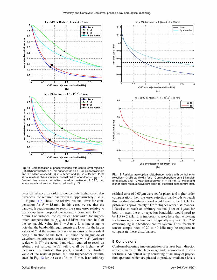
layer disturbance. In order to compensate higher-order dis-turbances, the required bandwidth is approximately 3 kHz.
Figure 11(b) shows the relative residual error for com-pensation for δ� ¼ 15 mm. In this case, we see that thebandwidth requirements to reach the same error relative toopen-loop have dropped considerably compared to δ� ¼5 mm. For instance, the equivalent bandwidth for higher-order compensation is f3dB ≃ 1.5 kHz; less than half ofthe comparable value for δ� ¼ 5 mm. It is interesting tonote that the bandwidth requirements are lower for the largervalues of δ�, if the requirement is cast in terms of the residualbeing a fraction of the total. But since the magnitude ofwavefront disturbances scales up linearly with δ� (variancescales with δ�2 ) the actual bandwidth required to reach anarbitrary set residual WFE will overall be higher as δ�increases. To illustrate this point, consider the absolutevalue of the residual piston, tilt, and higher-order disturb-ances in Fig. 12 for the case of δ� ¼ 15 mm. If an arbitrary
residual error of 0.05 μmwere set for piston and higher-ordercompensation, then the error rejection bandwidth to reachthis residual disturbance level would need to be 1 kHz forpiston and approximately 2 Hz for higher-order disturbances.Likewise, to reach an arbitrary residual jitter of 1 μrad forboth tilt axes, the error rejection bandwidth would need tobe 1.5 to 2 kHz. It is important to note here that achievingsuch error rejection bandwidths typically requires 10 to 20×oversampling in a feedback control system. Thus, feedbacksensor sample rates of 20 to 40 kHz may be required tocompensate these disturbances.
5 ConclusionsConformal-aperture implementation of a laser beam directorreduces many of the large-magnitude aero-optical effectsfor turrets. An optical setup consisting of an array of projec-tion apertures which are phased to produce irradiance levels
Fig. 11 Compensation of phase variance with control error rejection(−3 dB) bandwidth for a 10 cm subaperture on a 5 km platform altitudeand 1.0 Mach airspeed. (a) δ� ¼ 5 mm and (b) δ� ¼ 15 mm. Plotsshow residual phase variance normalized to open-loop (f −3dB ¼ 0).Dashed line shows normalized residual variance of 0.25, i.e.,where wavefront error or jitter is reduced by 1/2.
0 0.5 1 1.5 2 2.5 30
0.02
0.04
0.06
0.08
0.1
0.12
0.14
−3dB error rejection bandwidth (kHz)
Res
idua
l WF
E (
µm)
hp = 5000 m, Mach = 1, β = 45°, δ* = 15 mm
pistonhigher−order
0 0.5 1 1.5 2 2.5 30
0.5
1
1.5
2
2.5
3
3.5
−3dB error rejection bandwidth (kHz)
Res
idua
l jitt
er (
µrad
)
hp = 5000 m, Mach = 1, β = 45°, δ* = 15 mm
X−tiltY−tilt
Fig. 12 Residual aero-optical disturbance modes with control errorrejection (−3 dB) bandwidth for a 10 cm subaperture on a 5 km plat-form altitude and 1.0 Mach airspeed with δ� ¼ 15 mm. (a) Piston andhigher-order residual wavefront error. (b) Residual subaperture jitter.
Optical Engineering 071409-9 July 2013/Vol. 52(7)
Whiteley and Gordeyev: Conformal phased array aero-optical modeling. . .
similar to a full aperture system are an attractive option forlaser systems on high-speed aircraft. Conformal arrays willstill be subject to aero-optical disturbances resulting from theturbulent boundary layer on the aircraft surface. Theoreticalmodels of boundary layer aero-optics have been validatedthrough wind tunnel measurements which may be appliedto analysis of conformal phased array performance andthe AO compensation requirements for these disturbances.
Using available models, turbulent boundary layer wave-front disturbances were found to be >λ∕10 (at λ ¼ 1 μm) foraircraft speeds greater than Mach 0.8 over wide range ofoperating altitudes. Based on estimates of displacementthickness δ� flight regimes of interest, δ� ¼ 15 mm wasemployed in our phased array modeling for an aircraft at5 km altitude at Mach 1.0. We used a 7-aperture hexagonalpattern of apertures with 10 cm diameter as a baseline in ourmodeling. These studies show turbulent boundary layer pis-ton and tilt dominate and are nearly equal in effect on thephased array irradiance. Higher-order disturbances are nearlyas strong as piston for this array configuration. These higher-order wavefront disturbances for boundary layer aero-opticswere shown to be twice as large as the upper bound on free-stream disturbances in an ideally sized phased array subaper-ture. To achieve a residual error of 0.05 μm for piston andhigher-order compensation, the error rejection bandwidth fora temporal feedback controller would need to be 1 kHz forpiston and approximately 2 Hz for higher-order disturbances.For a residual jitter of 1 μrad, the error rejection bandwidthwould need to be 1.5 to 2 kHz. Achieving such error rejec-tion bandwidths in a feedback controller would require sen-sor sample rates of 20 to 40 kHz in a beam control system forthe aircraft flight conditions analyzed here.
AcknowledgmentsThe authors acknowledge significant contributions of othercollaborators at the University of Notre Dame (UND), nota-bly Jacob Cress who provided code examples which were thebasis for the phase screen modeling approach used in thisproject. This research was supported by the Air ForceResearch Laboratory (AFRL) Directed Energy Directorateunder contract number FA9451-11-C-0191 and has beencleared for public release by the 377th Air Base WingOffice of Public Affairs, Kirtland AFB, New Mexico.
References
1. S. Gordeyev and E. Jumper, “Fluid dynamics and aero-optics of turrets,”Prog. Aerospace Sci. 46(8), 338–400 (2010).
2. J. Cress, S. Gordeyev, and E. Jumper, “Aero-optical measurements in aheated, subsonic, turbulent boundary layer,” in 48th AIAA AerospaceScience Meeting and Ex-hibit, Orlando, FL, pp. 4–7 (2010).
3. ADA-035728, Handbook of Geophysics and the Space Environment,U.S. Standard Atmosphere, 1976, National Oceanic and AtmosphericAdministration, Washington, DC (1976).
4. Ames Research Staff, “Equations, tables and charts for compressibleflows,” Tech. Rep. NASA Report 1135 (1953), Reprinted byTechPress Publishing Co., North Olmstead, OH (1992).
5. S. Gordeyev, E. Jumper, and T. E. Hayden, “Aero-optical effects ofsupersonic boundary layers,” AIAA J. 50(3), 682–690 (2012).
6. J. A. Cress, “Optical aberrations caused by coherent structures in a sub-sonic, compressible, turbulent boundary layer,” Ph.D. Thesis,University of Notre Dame, Notre Dame, IN (2010).
7. J. Cress et al., “Aero-optical measurements in a turbulent, subsonicboundary layer at different elevation angles,” in 39th AIAAPlasmadynamics and Lasers Conf., Seattle, Washington, Vol. 4214,pp. 23–26 (2008).
8. D. J. Wittich, S. Gordeyev, and E. J. Jumper, “Revised scaling of opticaldistortions caused by compressible, subsonic turbulent boundarylayers,” in 38th AIAA Plasmady- namics and Lasers Conf., Miami,Florida, Vol. 4009, pp. 25–28 (2007).
9. S. Gordeyev, E. J. Jumper, and T. Hayden, “Aero-optics of supersonicboundary layers,” in AIAA 2011-1325 (2011).
10. D. L. Fried, “Optical resolution through a randomly inhomogeneousmedium for very long and very short exposures,” J. Opt. Soc. Am.56(10), 1372–1379 (1966).
11. M. C. Roggemann and B. Welsh, Imaging Through Turbulence, CRCPress, Boca Raton (1996).
12. M. R. Whiteley et al., “Adaptive controls for aero-optics and atmos-pheric compensation,” Tech. Rep. AFRL-DE-PS-TR-2007-1044, AirForce Research Laboratory, Directed Energy Directorate, KirtlandAFB, New Mexico (2007), Contract Number FA9451-06-M-0128,MZA Associates Corporation.
13. M. R. Whiteley and J. S. Gibson, “Adaptive laser compensation for aerooptics and atmospheric disturbances,” in 38th AIAA Plasmadynamicsand Lasers Conf., Vol. 4012 (2007).
14. M. R. Whiteley and R. J. Drye, “Adaptive controls for aero-optics andatmospheric compensation (phase II),” Tech. Rep. AFRL-RD-PS-TR-2010-1012, Air Force Research Laboratory, Directed EnergyDirectorate, Kirtland AFB, New Mexico (2010), Contract NumberFA9451-07-C-0030, MZA Associates Corporation.
15. B. L. Ellerbroek, “First-order performance evaluation of adaptive-opticssystems for atmospheric turbulence compensation in extended-field-of-view astronomical telescopes,” J. Opt. Soc. Am. A 11(2), 783–805(1994).
16. G. A. Tyler, “Bandwidth considerations for tracking through turbu-lence,” J. Opt. Soc. Am. A 11(1), 358–367 (1994).
Matthew R. Whiteley received his MS(1995) and PhD (1998) in physics from theAir Force Institute of Technology. Hereceived a BS in physics from CarnegieMellon University in 1991. From 1998 to2002, he was a deputy chief and advancedconcepts team lead at the Airborne LaserTechnology Branch of the U.S. Air ForceResearch Laboratory. From 2002 to 2005,he was a group leader and senior researchscientist at Mission Research Corporation,
and he is now a vice president and senior scientist at MZAAssociates Corporation. His research interests include optical turbu-lence, aero-optical flow, adaptive optics, and wave-optics simulations.
Stanislav Gordeyev is a research associateprofessor in the Department of Aerospaceand Mechanical Engineering, University ofNotre Dame. He is an internationally recog-nized expert in investigating optical distor-tions caused by compressible turbulentflows around airborne systems. His expertiseincludes performing complex experimentalinvestigations of optical aberrations, both ina time-averaged and instantaneous sense,in boundary layers, shear layers and wakes,
as well as around complex geometries, like side-mounted turrets atsubsonic and transonic speeds; experimental results and developedmodels are currently widely used to design laser airborne systems, aswell to validate computational codes to predict optical distortionscaused by turbulent flows. He is also actively involved in various stud-ies of different mitigation techniques to improve the overall optical per-formance of airborne systems.
Optical Engineering 071409-10 July 2013/Vol. 52(7)
Whiteley and Gordeyev: Conformal phased array aero-optical modeling. . .