Embed Size (px)
Citation preview

Phys. Status Solidi A 207, No. 11, 2578–2584 (2010) / DOI 10.1002/pssa.201026147 p s sa
statu
s
soli
di
www.pss-a.comph
ysi
ca
applications and materials science
Phase transition, microstructure, andelectric-field-induced large strain inBi0.5(Na0.85K0.15)0.5TiO3-BiAlO3
lead-free piezoelectric ceramics
Aman Ullah1, Chang Won Ahn2, and Ill Won Kim*,1
1Department of Physics, University of Ulsan, Ulsan 680-749, South Korea2Convergence Components R&D Division, KETI, Seongnam-si, 463-816, South Korea
Received 22 March 2010, revised 2 July 2010, accepted 7 July 2010
Published online 10 August 2010
Keywords ferroelectricity, phase transitions, piezoelectricity, strain, titanates
*Corresponding author: e-mail [email protected], Phone: þ82 52 259 2323, Fax: þ82 52 259 1693
Lead-free (1� x)(Bi0.5(Na0.85K0.15)0.5TiO3)-xBiAlO3 (abbre-
viated as BNKT15-BA, x¼ 0, 0.025, 0.050, 0.075, 0.100)
piezoelectric ceramics were synthesized by a conventional
solid-state reaction method. The phase-transition behavior in
BNKT15-BA ceramics with respect to changes in composition
were investigated using X-ray diffraction analysis, dielectric
and ferroelectric characterizations, and electric-field-induced
strain. The results of X-ray diffraction revealed that a pure
perovskite phase was formed for x� 0.050. A phase transition
from the coexistence of rhombohedral and tetragonal to a
pseudocubic phase was observed at x¼ 0.050. The dielectric
constant continuously decreased with increase in BA content,
and the depolarization temperature (Td) was shifted toward
lower temperature. The polarization and strain hysteresis
loops indicate that the ferroelectric order of BNKT15
ceramics is disrupted significantly with the addition of BA.
The destabilization of ferroelectric order is accompanied by an
enhancement of bipolar and unipolar strains, and a large
electric-field-induced strain (S¼ 0.21%) and a normalized
strain (d�33 ¼ Smax/Emax¼ 276 pm/V) were obtained at x¼0.050. These results suggested that the BNKT15-BA system
can be employed in lead-free electromechanical devices.
� 2010 WILEY-VCH Verlag GmbH & Co. KGaA, Weinheim
1 Introduction Extensive research has been carriedout on lead-based piezoelectric ceramics, such as leadzirconate titanate (PZT), due to their excellent piezoelectricproperties [1–3]. However, environmental issues call for theuse of nonhazardous substances for device fabrication,makingthe replacement of lead-containing ceramics imperative [4, 5].Bismuth sodium titanate, (Bi0.5Na0.5)TiO3 (BNT), is con-sidered to be an excellent candidate to replace lead-containingpiezoelectric ceramics. BNT ceramics exhibit a large remnantpolarization (Pr¼ 38mC/cm2) at room temperature [6].However, poling of pure BNT ceramics is difficult due to itshigh coercive field (Ec¼ 73 kV/cm), and it is therefore achallenge to obtain the desired piezoelectric properties.Recently, the formation of solid solutions of BNT ceramicswith BaTiO3 (BT) [7, 8], SrTiO3 [9, 10], NaNbO3 [11],KNbO3 [12], Bi0.5K0.5TiO3 (BKT) [13–17], BiFeO3, andBiScO3 [18, 19], has proven to be helpful in the polingprocess.
Among BNT-based solid solutions that have beendeveloped so far, the BNT–BKT system has received agreat deal of attention due to their excellent ferroelectric andpiezoelectric properties and their near rhombohedral–tetragonal morphotropic phase boundary (MPB) compo-sition [14, 16, 17]. In the BNT–BKT (BNKT) binary systemthe rhombohedral side of the MPB composition possessexcellent electromechanical coupling factor [14]. RecentlyZhao et al. [17] reported that the compositions near therhombohedral side of MPB enjoy better piezoelectricproperties. In this respect, the composition close to therhombohedral side of the MPB, Bi0.5(Na0.85K0.15)0.5TiO3
was selected as a matrix material.BiAlO3 (BA) has recently attracted considerable atten-
tion due to its excellent ferroelectricity. Theoreticalcalculations predict that BA has a very large spontaneouspolarization of about 76mC/cm2 and a Curie temperature ofabout 800K [20]. Moreover, theoretical calculations predict
� 2010 WILEY-VCH Verlag GmbH & Co. KGaA, Weinheim
Phys. Status Solidi A 207, No. 11 (2010) 2579
Original
Paper
Figure 1 (online color at: www.pss-a.com) X-ray diffraction(XRD) patterns of (1� x)BNKT15-xBA ceramics (x¼ 0.00,0.025, 0.050, 0.075, and 0.100) in the 2u ranges of (a) 208–608(b) 398–418, and (c) 448–488, (�) denotes the secondary phase.
its crystal structure to have perovskite-like rhombohedralsymmetry at room temperature [20]. Zylberberg et al. havesynthesized BA and have confirmed that it is indeedferroelectric and has a Curie temperature Tc> 520 8C [21].The dielectric, ferroelectric, and piezoelectric properties ofBA are comparable to those of BiFeO3 and SrBi2Ta2O9,making it a promising new high-Tc, lead-free ferroelectricmaterial for memory applications. However, the poorthermal stability and extreme conditions used to synthesizethis material limit its usability in technological applications[21]. Therefore, it is favorable to stabilize BA byincorporating it into other perovskite materials to form solidsolutions. Watanabe et al. [22] have fabricated (1� x)(Bi0.5Na0.5)TiO3-xBiAlO3 ferroelectric ceramics and eval-uated their electrical properties. Recently, Yu and Ye havesynthesized a (1� x)(Na0.5Bi0.5)TiO3-xBiAlO3 (NBT-BA)ceramic system and reported remarkable ferroelectricand piezoelectric properties compared to pureNBT ceramics[23]. However, to the best of our knowledge there areno reports on (1� x)(Bi0.5(Na0.85K0.15)0.5TiO3)-xBiAlO3
ceramics to date, even though the system has manyinteresting properties.
In this study, solid-solution ceramics between two lead-free candidates, Bi0.5(Na0.85K0.15)0.5TiO3 (BNKT15) andBiAlO3 (BA) were investigated from the standpoint of phasetransitions and the electric-field-induced strain behavior wasanalyzed as a function of composition.
2 Experimental procedure (1� x)BNKT15-xBA(0� x� 0.10) ceramics were prepared by a conventionalsolid-state reaction method using Bi2O3, TiO2 (99.9%, HighPurity Chemicals), Na2CO3 (99.9%, Cerac specialty inor-ganics), K2CO3 (�99%, Sigma–Aldrich), and Al2O3
(99.9%, High Purity Chemicals) as raw starting materials.Before weighing, these powders were first dried in an oven at100 8C for 12 h. For each composition, the starting materialswere weighed according to the stoichiometric formula andball milled for 24 h in ethanol with zirconia balls. The driedslurries were calcined at 800 8C for 2 h and then ball milledagain for 24 h. The powders were pulverized, mixed with anaqueous polyvinyl alcohol (PVA) solution and pressed intogreen disks with a diameter of 13mm under 100MPapressure.
Sintering was carried out at 1170 8C for 2 h in coveredalumina crucibles. To prevent the vaporization of Bi, Na, andK, the disks were embedded in a powder of the samecomposition. The relative density of all samples wasdetermined by the Archimedes method. The crystal struc-tures of the ceramics were characterized using an X-raydiffractometer (XRD, X’pert PRO MRD, Philips, in theBusan center, KBSI). The microstructure was observedusing a scanning electronmicroscopy (SEM, JSM-5610LV).Electric measurements were carried out on sintered disks.Silver paste was applied on the lapped surfaces of the disks toserve as the electrode. The temperature dependences of thedielectric properties were measured using an impedanceanalyzer (HP4192A) in the temperature range of 30–550 8C.
www.pss-a.com
The ferroelectric hysteresis loops were measured using aconventional Sawyer–Tower to apply an electric field with atriangular waveform. The electric-field-induced strain wasmeasured using a linear variable differential transducer(LVDT, Mitutoyo MCH-331 & M401). The voltage wassupplied using a high-voltage amplifier (Trek, 610E) drivenby waveform generator (Agilent 33250A). The normalizedstrain (d�33 ¼ Smax/Emax) was calculated from the ratio ofthe maximum strain to the maximum electric field, inthe unipolar strain-field curves. The samples were poledat 50 8C in silicon oil by applying an electric field of3–4 kV/mm for 30min, and the specimens were then cooledto room temperature in the electric field. The piezoelectricconstant d33 was measured using a piezo-d33 meter (ZJ-6B,China).
3 Results and discussion Figure 1a shows X-raydiffraction patterns of the (1� x)BNKT15-xBA (x¼ 0.00,0.025, 0.050, 0.075, and 0.100) ceramics in the 2u range of208–608. All the samples with x� 0.050 exhibited a pureperovskite structure, indicating the formation of a(1� x)BNKT15-xBA solid solution. A secondary phasewas detected at x¼ 0.075. This secondary phase wasidentified as Bi2Al4O9 (PDFNo. 74-1097), and is designatedby a star in the XRD pattern. The appearance of impurityphases indicates that the solubility limit of BA in BNKT15 isat x� 0.075. This is probably due to the instability of the BAperovskite structure, which decomposes at high tempera-tures [21]. Figures 1b and c illustrate detailed XRD analysisin the 2u range of 398–418 and 448–488, respectively. It isknown that BNT is rhombohedral whereas BKT is tetragonalat room temperature. A rhombohedral–tetragonal MPB inthe solid solutions of BNT–BKT [Bi0.5(Na1–xKx)0.5]TiO3
exist near x¼ 0.16–0.20 [14, 16, 17]. As shown in Figs. 1band c, BNKT15-BA ceramic with x¼ 0 has features of bothrhombohedral and tetragonal symmetry, as evidenced by the
� 2010 WILEY-VCH Verlag GmbH & Co. KGaA, Weinheim
2580 A. Ullah et al.: Phase transition, microstructure and strain in Bi0.5(Na0.85K0.15)0.5TiO3 –BiAlO3p
hys
ica ssp st
atu
s
solid
i a
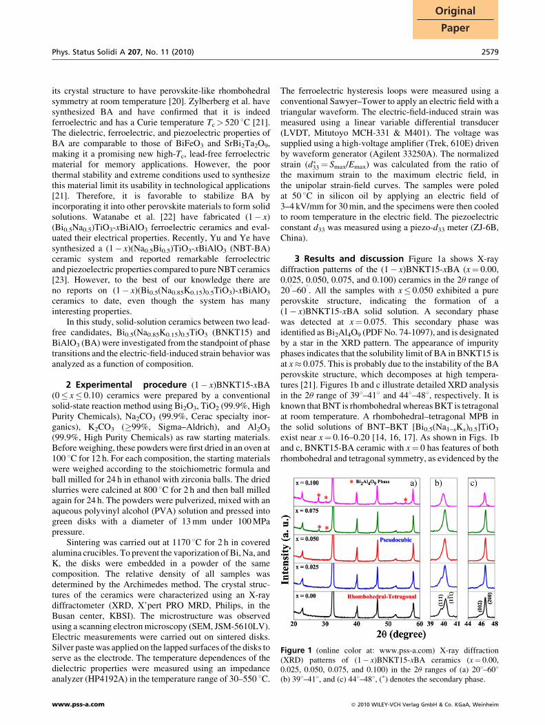
Figure 2 SEM micrographs of (1� x)BNKT15-xBA ceramicssintered at 1170 8C for 2 h: (a) x¼ 0.00, (b) x¼ 0.025, (c) x¼ 0.050,(d) x¼ 0.075, and (e) x¼ 0.100.
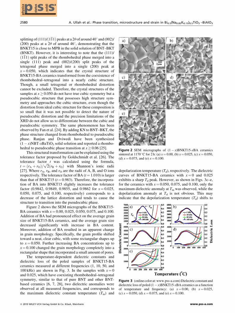
Figure 3 (onlinecolor at:www.pss-a.com)Dielectric constant anddielectric loss of poled (1� x)BNKT15-xBA ceramics as a functionof temperature and frequency: (a) x¼ 0.00, (b) x¼ 0.025,(c) x¼ 0.050, (d) x¼ 0.075, and (e) x¼ 0.100.
splitting of (111)/ð111Þ peaks at a 2u of around 408 and (002)/(200) peaks at a 2u of around 468, demonstrating that theBNKT15 is close to MPB in the solid solution of BNT–BKT(BNKT). However, it is interesting to note that the (111)/ð111Þ split peaks of the rhombohedral phase merged into asingle (111) peak and (002)/(200) split peaks of thetetragonal phase merged into a single (200) peak atx¼ 0.050, which indicates that the crystal structure ofBNKT15-BA ceramics transformed from the coexistence ofrhombohedral–tetragonal into a nearly cubic structure.Though, a small tetragonal or rhombohedral distortioncannot be excluded. Therefore, the crystal structures of thesamples at x� 0.050 do not have true cubic symmetry but apseudocubic structure that possesses high structure sym-metry and approaches the cubic structure, even though thedistortion from ideal cubic structure for these composition isso small that it was not possible to detect the nature ofpseudocubic distortion and the precision limitations of theXRD do not allow us to differentiate between the cubic andpseudocubic symmetry. The same phenomenon has beenobserved by Fan et al. [24]. By adding KN to BNT–BKT, thephase structure changed from rhombohedral to pseudocubicphase. Ranjan and Dviwedi have been synthesized(1� x)NBT-xBaTiO3 solid solution and reported a rhombo-hedral to pseudocubic phase transition at x� 0.06 [25].
This structural transformation can be explained using thetolerance factor proposed by Goldschmidt et al. [26]. Thetolerance factor t was calculated using the formula,t ¼ ðrA þ rOÞ=
ffiffiffi
2p
ðrB þ rOÞ with Shannon’s ionic radii[27]. Where rA, rB, and rO are the radii of A, B, and O ionsrespectively. The tolerance factor of BA (t¼ 1.010) is largerthan that of BNKT15 (t¼ 0.983). Therefore, the incorpora-tion of BA into BNKT15 slightly increases the tolerancefactor (0.9842, 0.9849, 0.9855, and 0.9862 for x¼ 0.025,0.050, 0.075, and 0.100, respectively) corresponds to adecrease of the lattice distortion and tends to cause thestructure to transition into the pseudocubic phase.
Figure 2 shows the SEM micrographs of the BNKT15-BA ceramics with x¼ 0.00, 0.025, 0.050, 0.075, and 0.100.Addition of BA had pronounced effect on the average grainsize of BNKT15-BA ceramics, and the average grain sizedecreased significantly with increase in BA content.Moreover, addition of BA resulted in an apparent changein grain morphology. Specifically, the grain profile shiftedtoward a neat, clear cubic, with some rectangular shapes upto x¼ 0.050. Further increasing BA concentrations up tox¼ 0.100 changed the grain morphology completely into arectangular shape that incorporated a small amount of pores.
The temperature-dependent dielectric constants anddielectric loss of the poled samples of BNKT15-BAceramics measured at different frequencies (1, 10, 50, and100 kHz) are shown in Fig. 3. In the samples with x¼ 0and 0.025, which have coexisting rhombohedral–tetragonalsymmetry, similar to that of pure BNT and other BNT-based ceramics [6, 7, 28], two dielectric anomalies wereobserved at all measured frequencies, and corresponds tothe maximum dielectric constant temperature (Tm) and
� 2010 WILEY-VCH Verlag GmbH & Co. KGaA, Weinheim
depolarization temperature (Td), respectively. The dielectriccurves of BNKT15-BA ceramics with x¼ 0 and 0.025exhibits a sharp Td peak. However, as shown in Figs. 3c–e,for the ceramics with x¼ 0.050, 0.075, and 0.100, only themaximum dielectric anomaly at Tm was observed, while thedepolarization anomaly at Td is not obvious. This mayindicate that the depolarization temperature (Td) shifts to
www.pss-a.com

Phys. Status Solidi A 207, No. 11 (2010) 2581
Original
Paper
Figure 4 (online color at: www.pss-a.com) P–E hysteresis loopsof BNKT15-BA piezoelectric ceramics.
lower temperature with increasing BA addition. Similarbehavior is observed in La3þ substitution 0.94BNT-0.06BTceramics [29], where the dielectric anomaly at Td disappearsafter high substitution of La3þ for Bi3þ. The observedmaximumdielectric anomaly at Tm provide evidence that thecrystal structures of the sample at x� 0.050 do not have truecubic symmetry but a pseudocubic structure that possesseshigh structure symmetry and approaches the cubic structure.In BNKT15-BA ceramics, the variation ofTd with increasingamount of BA may be attributed to the phase transition fromcoexistence of rhombohedral–tetragonal to pseudocubicphase. It can also be noted from Fig. 3 that the maximumdielectric peaks at Tm for all the ceramics are relativelybroad, suggesting that the phase transition at Tm is a diffusephase transition. A diffuse phase transition has also beenobserved in other BNT-based ceramics [30].
It is well known that the dielectric constant is related tothe phase structure and the domain alignment. For BNKT15,which has coexisting rhombohedral and tetragonal sym-metry at room temperature, the value of the dielectricconstant at Tm is 6623. However, for the sample withx¼ 0.050, which has pseudocubic symmetry at roomtemperature, the dielectric constant at Tm decreased sharplyto 4139. The marked decrease in the dielectric constant atx¼ 0.050 is consistent with the phase-transition point inXRD analysis. In addition, this significant decrease ofmaximum dielectric constant at x� 0.050 ascribed to thedecreased polarization in the ceramics. Because BAincorporation reduces the extent of anisotropy in the crystalstructure, and the ferroelectric stability weakens. Thedielectric constant and dielectric loss of BNKT15-BAceramics at a frequency of 1 kHz are summarized inTable 1. The dielectric loss of BNKT15-BA ceramicsincreased slightly with increasing BA content and varies inthe range of 0.04–0.08.
Figure 4 shows the P–E hysteresis loops of(1� x)BNKT15-xBA ceramics measured at room tempera-ture. BNKT15-BA ceramics without the addition of BAexhibit well-saturated square-like P–E hysteresis loophaving large remnant polarization and maximum polariz-ation of 31 and 40mC/cm2, respectively, and a coercive fieldof 46 kV/cm. As the hysteresis curves show, BA exerts asignificant influence on the loop shape and polarizationvalues. The remnant polarization (Pr), maximum polariz-ation (Pm), and coercive field (Ec) of BNKT15-BA ceramicsare summarized in Table 1. Pr and Ec were found to decrease
Table 1 Electrical properties of (1� x)BNKT15-xBA lead-free pie
xvalue
Pm
(mC/cm2)Pr
(mC/cm2)Ec
(kV/cm)e
1 kHztan d1 kHz
0.00 40 31 46 6623 0.0440.025 33 24 43 5064 0.0360.050 26 13 25 4139 0.0490.075 23 6 16 3306 0.0430.100 15 3 13 2734 0.075
www.pss-a.com
with an increase of BA content. However, at x¼ 0.050, thereis a significant decrease inPr from 31 to 13mC/cm2 and in Ec
from 46 to 25 kV/cm, and the hysteresis curve became slim.The composition of x¼ 0.050, which corresponds to thetransitional point in the shape of the hysteresis loop, agreeswell with the phase-transition point in XRD analysis. Athigher BA concentration, both Pr and Ec were drasticallylower and the hysteresis curve slimmed, nearly exhibitingalmost the character of a lossy ferroelectric. According topoint group theory of ferroelectric, the perovskite-typematerial with cubic symmetry has no spontaneous polariz-ation vector in the crystal cell [24]. In BNKT-BA ceramics,though the ferroelectric order of BNKT15 is disrupted by theaddition of BA. However, the presence of traces offerroelectric order at higher BA content at zero electric fieldis also evident, since remnant polarization is not negligible(Pr¼ 3mC/cm2 at x¼ 0.100). This again revealed the factthat the crystal structures of the samples at x� 0.050 do nothave true cubic symmetry but a pseudocubic structure thatpossesses high structure symmetry and approaches the cubicstructure. Similar results have been reported by Seifert et al.Adding a small amount ofKNN toBNT–BKT, resulted in thedestabilization of ferroelectric order of BNT–BKT [31].Moreover, the piezoelectric constant d33 also drasticallydecreased from 135 pC/N for BNKT15 to 62 pC/N forx¼ 0.050, as shown in Table 1. Here, the drastic decrease ind33 at x¼ 0.050 can be explained using the thermodynamic
zoelectric ceramics.
d33(pC/N)
neg. strain(%)
strain(%)
Smax/Emax
(pm/V)hysteresis
(%)
135 0.13 0.15 196 28.6128 0.11 0.17 220 23.562 0.07 0.21 276 20.224 0.023 0.18 233 28.616 0.008 0.11 142 35.2
� 2010 WILEY-VCH Verlag GmbH & Co. KGaA, Weinheim

2582 A. Ullah et al.: Phase transition, microstructure and strain in Bi0.5(Na0.85K0.15)0.5TiO3 –BiAlO3p
hys
ica ssp st
atu
s
solid
i a
Figure 6 Negative strain (%) as a function of x in (1� x)BNKT15-xBA ceramics.
theory of ferroelectrics [32]. According to this theory, theintrinsic piezoelectric and dielectric properties are related bythe equation: d33¼ 2Q11PreT33, where Q11 represent theelectrostrictive coefficients that are constant for perovskitematerials, Pr and eT33 represent the remnant polarization anddielectric constant of the material. Since d33 is proportionalto the remnant polarization (Pr), and at x¼ 0.050, the Pr
value is drastically decreased from 31mC/cm2 for BNKT15to 13mC/cm2, results in significant reduction of d33. Athigher BA content (x¼ 0.100), the Pr is so small, so that avery small value of piezoelectric constant (d33¼ 16 pC/N)was observed.
Figure 5 shows bipolar electric-field-induced straincurves of BNKT15-BA ceramics. BNKT15-BA ceramicwith x¼ 0.00 exhibits a butterfly-type strain curve typical offerroelectric materials with a maximum strain of 0.15%.Strain increased significantly with increase in BA content. Amaximum strain of 0.21% was obtained for BNKT15-BAceramics at x¼ 0.050. A decrease in strain occurred as theBA concentration was further increased. On the other hand,the ‘‘negative strain’’, which denote the difference betweenzero-field strain and the lowest strain [33], decreased withincreasing BA content. The negative strain is summarized asa function of BA content in Fig. 6, and also listed in Table 1.At x¼ 0.050, the negative strain sharply decreased from�0.13% for BNKT15 to�0.07%, and the strain curve showsslight deviation from the typical butterfly shape. Beyond thiscomposition, the negative strain graduallymoved to zero andthe strain loop exhibited drastic deviation from typicalferroelectric materials. We suggest the following expla-nation for the observed bipolar strain behavior in BNKT15-
Figure 5 (online colour at: www.pss-a.com) Bipolar S–E loops ofBNKT15-BA piezoelectric ceramics.
� 2010 WILEY-VCH Verlag GmbH & Co. KGaA, Weinheim
BA ceramics. At lower BA content (x� 0.025); the sampleshave coexisting rhombohedral–tetragonal symmetry, and theP–E loops and bipolar S–E loops display typical ferroelectriccurve, so that the ferroelectric phase is dominant, andcontributed to the strain. At x¼ 0.050, the crystal structurechanged to pseudocubic phase, so that an electric field-induced phase transition from pseudocubic to ferroelectriccontributed to the strain, resulting in large strain. Beyond thisnarrow region, the pseudocubic phase dominates (i.e.,Pr andPm significantly decreased, and theP–E loop and strain curveshows drastic deviation from typical ferroelectric materials)and the electric-field-induced phase transformation mayoccur gradually, resulting in the observed low strain.
Figure 7 shows unipolar electric-field-induced straincurves of BNKT15-BA ceramics measured at room
Figure 7 (online color at: www.pss-a.com) Unipolar S–E loops ofBNKT15-BA piezoelectric ceramics.
www.pss-a.com

Phys. Status Solidi A 207, No. 11 (2010) 2583
Original
Paper
temperature. Similar to bipolar stain, the unipolar strain alsoincreased with increasing BA concentration until x¼ 0.050,followed by a decrease with increasing concentration. Alarge strain (S¼ 0.21%) and the normalized strain(d�33 ¼ Smax/Emax¼ 276 pm/V) were obtained at x¼ 0.050.The field-induced strain S (%) and the normalized strain d�33of BNKT15-BA ceramics as a function of BA content aredepicted in Fig. 8a. The detailed maximum strain S (%) andd�33 values are shown in Table 1. The strain hysteresis (%) ofBNKT15-BA ceramics versus BA content is plotted inFig. 8b, and also shown in Table 1. The strain hysteresis wascalculated using the relation from Ref. [34]. Strainhysteresis¼ (hysteresis in strain at half of the maximumelectric field/strain at the maximum electric field) � 100%.The strain hysteresis of the unipolar S–E curve graduallydecreased up to x¼ 0.050, and then increases. At x¼ 0.050,the hysteresis is as low as 20%, while the maximum strainreached 0.21%, suggesting that BNKT15-BA ceramics withx¼ 0.050 may be useful for electronic devices. We suggestfollowing explanation for the observed variation of the strainhysteresis.
At x¼ 0.050, the sample is at an ‘‘early’’ stage of thepseudocubic phase. At this stage, the grains may easilyundergo an electric-field induced, pseudocubic to ferro-electric phase transformation. At x� 0.075, the sample is abit deeper in the pseudocubic phase, many more grains havetransformed into the pseudocubic phase and due to internalstresses the electric-field-induced phase transformationmay occur gradually. However, the actual origin of thisphenomenon is not clear, and need some further investi-gations to explore this fact. Large electric-field-induced
Figure 8 (online color at: www.pss-a.com) (a) Strain (%), andnormalized strain d�33, (b) unipolar strain hysteresis (%) as functionsof x in (1� x)BNKT15-xBA ceramics.
www.pss-a.com
strain has been reported in other BNT-based ceramics [35–37]. However, these reported BNT-based ceramics displaylarge hysteresis, limiting their applications in electronicdevices.
Zhang et al. [36] reported a giant strain in B0.5N0.5TiO3-BaTiO3-K0.5Na0.5NbO3 piezoelectric ceramics. However,X-ray investigations describe the crystal structure aspseudocubic and transmission electron microscopy investi-gations have not found a domain structure [38]. Based onelectrical measurements, a field-induced phase transform-ation has been suggested [36, 38], and was furthercorroborated by acoustic emission work [39]. Recently,Daniels et al. [40] reported electric-field-dependent crystalstructure investigations on aBNT–BT piezoelectric ceramic,and monitored the structural and microstructural behavior ofthe material by high-energy X-ray diffraction. They demon-strated that the large strain observed in the lead-free93%(Bi0.5Na0.5)TiO3–7%BaTiO3 system arises from anelectric-field-induced phase transformation from a pseudo-cubic to a tetragonal structure.
BA is indeed ferroelectric with rhombohedral symmetry[21], and the BNKT15 ceramic has coexisting rhombohe-dral–tetragonal symmetry, and exhibited a well-defined P–Eloop and bipolar S–E loop similar to that of ferroelectricmaterials [8]. However, the addition of BA transformed thecrystal structure of BNKT15-BA ceramics to pseudocubicsymmetry. As a result, the ferroelectric order of BNKT15ceramics is destabilized, and a decrease of Pr, Td, Ec, and d33is observed. The appearance of pseudocubic phase atx¼ 0.050 strongly indicates that the BNKT15-BA systemsmay also undergo a phase transition from a pseudocubic to aferroelectrically active polar phase (either rhombohedral ortetragonal) as reported in BNT-based systems [31, 36, 40],and the large strain at x¼ 0.050 may be a consequence of amixed contribution from an electric-field-induced phasetransition from a pseudocubic to a noncubic phase as well asferroelectric domain contribution from this field-inducedferroelectric phase. Therefore on the basis of structure, P–Ehysteresis loops together with S–E loops, our resultssuggested that this large strain at x¼ 0.050 can be attributedto the electric field-induced phase transition from pseudo-cubic to ferroelectric noncubic phase.
4 Conclusions Lead-free piezoelectric ceramics(1� x)(Bi0.5(Na0.85K0.15)0.5TiO3)-xBiAlO3 (BNKT15-BA,x¼ 0.00, 0.025, 0.050, 0.075, 0.100) were successfullysynthesized using a solid-state reaction method. A pureperovskite phase was formed for x� 0.050. The crystalstructure of BNKT15-BA ceramics changed from thecoexistence of rhombohedral–tetragonal into pseudocubicphase at x¼ 0.050. The dielectric constant at Tm decreasedwith increase in BA content, ascribed to the decreasedpolarization in the ceramics. The P–E loops and S–E loopsdemonstrated that the addition of BA destabilized theferroelectric order of BNKT15 ceramics, and the destabili-zation of the ferroelectric order is accompanied by anenhancement of bipolar and unipolar stain. The large
� 2010 WILEY-VCH Verlag GmbH & Co. KGaA, Weinheim

2584 A. Ullah et al.: Phase transition, microstructure and strain in Bi0.5(Na0.85K0.15)0.5TiO3 –BiAlO3p
hys
ica ssp st
atu
s
solid
i a
electric-field-induced strain (S¼ 0.21%) with small hyster-esis and the normalized strain (d
�
33¼ 276 pm/V), wereobtained at the phase-transition composition (x¼ 0.050).
Acknowledgements This work was supported by theMinistry of Education, Science Technology (MEST) and KoreaIndustrial Technology Foundation (KOTEF) through the HumanResource Training Project for Regional Innovation. The author alsoacknowledges the Priority Research Centers Program through theNational Research Foundation of Korea (NRF) funded by theMinistry of Education, Science and Technology (2009-0093818).
References
[1] G. H. Haertling, J. Am. Ceram. Soc. 82, 797 (1999).[2] L. E. Cross, Ferroelectrics 151, 305 (1994).[3] S. E. Park and T. R. Shrout, J. Appl. Phys. 82, 1804 (1997).[4] Y. Li, K. S. Moon, and C. P. Wong, Science 308, 1419
(2005).[5] L. E. Cross, Nature (London) 432, 24 (2004).[6] G. A. Smolenskii, V. A. Isupov, A. I. Agranovskaya, and N.
N. Krainik, Sov. Phys. Solid State (Engl. Transl.) 2, 265(1961).
[7] T. Takenaka, K. Maruyama, and K. Sakata, Jpn. J. Appl.Phys. 30, 2236 (1991).
[8] Y. M. Chiang, G. W. Farrey, and A. N. Soukhojak, Appl.Phys. Lett. 73, 3683 (1998).
[9] K. Sakata and Y. Masuda, Ferroelectrics 7, 347 (1974).[10] J. R. Gomah-Pettry, P. Marchet, A. Salak, V. M. Ferreira, and
J. P. Mercurio, Int. Ferroelectr. 61, 159 (2004).[11] T. Takenaka, T. Okuda, and K. Takegahara, Ferroelectrics
175, 196 (1997).[12] H. Ishii, H. Nagata, and T. Takenaka, Jpn. J. Appl. Phys. 40,
5660 (2001).[13] O. Elkechai, M. Manier, and J. P. Mercurio, Phys. Status
Solidi A 157, 499 (1996).[14] A. Sasaki, T. Chiba, Y. Mamiya, and E. Otsuki, Jpn. J. Appl.
Phys. 38, 5564 (1999).[15] G. O. Jones, J. Kreisel, and P. A. Thomas, Powder Diffr.
17(4), 301 (2002).[16] Z. Yang, B. Liu, L. Wei, and Y. Hou, Mater. Res. Bull. 43, 81
(2008).[17] W. Zhao, H. Zhou, Y. Yan, and D. Liu, Key Eng. Mater. 368–
372, (2008. (1908).
� 2010 WILEY-VCH Verlag GmbH & Co. KGaA, Weinheim
[18] H. Nagata, N. Koizumi, N. Kuroda, I. Igarashi, and T.Takenaka, Ferroelectrics 229, 273 (1999).
[19] H. Nagata and T. Takenaka, Jpn. J. Appl. Phys. 36, 6055(1997).
[20] P. Baettig, C. F. Schelle, R. LeSar, U. V. Waghmare, and N.A. Spaldin, Chem. Mater. 17, 1376 (2005).
[21] J. Zylberberg, A. A. Belik, E. Takayama-Muromachi, andZ.-G. Ye, Chem. Mater. 19, 6385 (2007).
[22] Y. Watanabe, Y. Hiruma, H. Nagata, and T. Takenaka, KeyEng. Mater. 388, 229 (2009).
[23] H. Yu and Z.-G. Ye, Appl. Phys. Lett. 93, 112902 (2008).[24] G. Fan, W. Lu, X. Wang, and F. Liang, Appl. Phys. Lett. 91,
202908 (2007).[25] R. Ranjan and A. Dviwedi, Solid State Commun. 135, 394
(2005).[26] V. M. Goldschmidt, T. Barth, G. Lunde, and W. Zachariasen,
Skr. Nor. Vidensk. Akad. Oslo, Mat. -Nat. Kl 2, 117 (1926).[27] R. D. Shannon, Acta Crystallogr., Sect. A 32, 751 (1976).[28] D. Lin and K. W. Kwok, Curr. Appl. Phys. 10, 422
(2010).[29] Q. Zheng, C. Xu, D. Lin, D. Gao, and K.W. Kwok, J. Phys. D:
Appl. Phys. 41, 125411 (2008).[30] Y. M. Ly, W. Chen, Q. Xu, J. Zhou, X. Gu, and S. Fang,
Mater. Chem. Phys. 94, 328 (2005).[31] K. T. P. Seifert, W. Jo, and J. Rodel, J. Am. Ceram. Soc. 93,
1392 (2010).[32] M. J. Haun, E. Furman, S. J. Jang, and L. E. Cross, Ferro-
electrics 99, 13 (1989).[33] S. T. Zhang, A. B. Kounga, E. Aulbach, and Y. Deng, J. Am.
Ceram. Soc. 91, 3950 (2008).[34] P. Kumar, S. Singh, O. P. Thakur, C. Prakash, and T. C. Geol,
Jpn. J. Appl. Phys. 43, 1501 (2004).[35] A. Hussain, C. W. Ahn, J. S. Lee, A. Ullah, and I. W. Kim,
Sens. Actuators: A Physical 158, 84 (2010).[36] S. T. Zhang, A. B. Kounga, and E. Aulbach, Appl. Phys. Lett.
91, 112906 (2007).[37] A. B. Kounga, S. T. Zhang, W. Jo, T. Granzow, and J. Rodel,
Appl. Phys. Lett. 92, 222902 (2008).[38] S. T. Zhang, A. B. Kounga, E. Aulbach, T. Granzow, W. Jo,
H. J. Kleebe, and J. Rodel, J. Appl. Phys. 103, 034107 (2008).[39] E. Dulkin, E. Mojaev, M. Roth, W. Jo, and T. Granzow, Scr.
Mater. 60, 251 (2009).[40] J. E. Daniels, W. Jo, J. Rodel, and J. L. Jones, Appl. Phys.
Lett. 95, 032904. (2009).
www.pss-a.com


![Piezoelectric Ceramics Characterization · 2011. 5. 13. · Cook and Jaffe published the book “Piezoelectric Ceramics” [4] that is still one of the most referenced works on piezoelectricity](https://img.dokumen.tips/doc/110x75/61236b6459de7648ad1bb6f1/piezoelectric-ceramics-characterization-2011-5-13-cook-and-jaffe-published.jpg)