Embed Size (px)
Citation preview

International Research Journal of Engineering and Technology (IRJET) e-ISSN: 2395 -0056
Volume: 03 Issue: 07 | July-2016 www.irjet.net p-ISSN: 2395-0072
© 2016, IRJET | Impact Factor value: 4.45 | ISO 9001:2008 Certified Journal | Page 109
PFC CUK CONVERTER FOR PMBLDCM DRIVE
Abin V Unni1 , Prof A V Unnikrishnan2
1PG Student (PCD),Dept. of EEE,MBCET, Trivandrum,kerala 2Assistant Professor,Dept. of EEE,MBCET, Trivandrum,kerala
---------------------------------------------------------------------***---------------------------------------------------------------------Abstract: This paper deals with a Cuk dc-dc converter as a
single stage power factor correction (PFC) converter for a
permanent magnet brushless DC motor (PMBLDCM) fed
through a diode rectifier (DBR) from a single phase AC mains.
This converter is used due to single stage requirement for dc
link voltage control with unity PF at ac mains. A three phase
voltage source inverter is used as an electronic commutator to
operate the PMBLDCM drive. A proportional plus integral (PI)
controller is used in loop control algorithm to control speed..
Voltage proportional to speed is compared with the rms value
of supply voltage to generate the reference current which is
used to compare with the actual current of the dc –dc
converter. Analysis are done for varying conditions of torque
and speed. As a modification fuzzy based PFC for BLDC drive
is implement.The model is designed with necessary controls
and modeled in MATLAB Simulink and simulated results are
presented.
Keywords: Cuk converter, Power factor correction (PFC), Cuk converter, permanent magnet brushless DC motor (PMBLDCM).
1 INTRODUCTION
The applications of PMBLDC motors are increasing in
the day to day life because of its features like low
maintenance, high efficiency, and wide speed range.
Brushless DC electric motor (BLDC motors ) also known
as electronically commutated motors , they are synchronous
motors that are powered by a DC electric source via an
integrated inverter/switching power supply, which produces
an AC electric signal to drive the motor. In this context, AC,
alternating current, does not imply a sinusoidal waveform,
but rather a bi-directional current with no restriction on
waveform. Additional sensors and electronics control the
inverter output amplitude and waveform (and therefore
percent of DC bus usage/efficiency) and frequency (i.e. rotor
speed).
The use of PMBLDCM in low power appliances are
increasing because of its features of high efficiency, wide
speed range and low maintenance [1-4]. The PMBLDCM are
used in various applications like air conditioning system,
electric traction etc. A PMBLDCM has torque directly
proportional to phase current and its back EMF, which is
proportional to the speed. So, it has a constant current in its
stator windings with variable voltage across its terminals
maintains constant torque in a PMBLDCM under variable
speed operation [1-4]. However, the control of VSI is done by
electronic commutation based on the rotor position signals
of the PMBLDC motor. The motor drive is fed from a single-
phase ac supply via a diode bridge rectifier (DBR) followed
by a capacitor at dc link. The dc link capacitor draws current
in short pulses. This will generate harmonics and yield poor
PF, resulting in poor power quality which lower the
efficiency. Therefore various PFC converter topologies are
available in order to meet the required IEC 61000-3-2
standard [7].
Drive is supplied via diode bridge rectifier and a
capacitor. But the capacitor draws pulsating currents which
results in harmonics due to an uncontrolled charging of the
dc link capacitor. So PFC converters are implemented in
front of the dc link capacitor for PFC correction. A PF
correction (PFC) converter among various available
converter topologies [3] is applicable for a PMBLDCM drive .
Among these topologies most of them use boost topology at
their front end. Here switching losses are high due to the
presence of the diode bridge. This affects the performance of
the whole drive system.
2. PROPOSED SPEED CONTROL SCHEME OF
PMBLDC MOTOR
The proposed speed control scheme which is based on
the control of the DC link voltage reference as an equivalent
to the reference speed is shown in fig 1.The rotor position
signals acquired by Hall effect sensors are used by an
electronic commutator to generate switching sequence for
the VSI feeding the PMBLDC motor, therefore, rotor-position
is required only at the commutation points [1-4].
International Research Journal of Engineering and Technology (IRJET) e-ISSN: 2395 -0056
Volume: 03 Issue: 07 | July-2016 www.irjet.net p-ISSN: 2395-0072
© 2016, IRJET | Impact Factor value: 4.45 | ISO 9001:2008 Certified Journal | Page 110
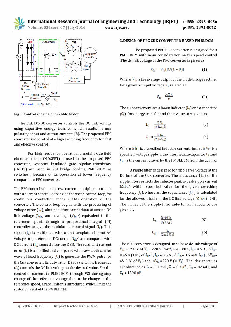
Fig 1. Control scheme of pm bldc Motor
The Cuk DC-DC converter controls the DC link voltage
using capacitive energy transfer which results in non
pulsating input and output currents [8]. The proposed PFC
converter is operated at a high switching frequency for fast
and effective control .
For high frequency operation, a metal oxide field
effect transistor (MOSFET) is used in the proposed PFC
converter, whereas, insulated gate bipolar transistors
(IGBTs) are used in VSI bridge feeding PMBLDCM as
switches , because of its operation at lower frequency
compared to PFC converter.
The PFC control scheme uses a current multiplier approach
with a current control loop inside the speed control loop, for
continuous conduction mode (CCM) operation of the
converter. The control loop begins with the processing of
voltage error ( ), obtained after comparison of sensed DC
link voltage ( ) and a voltage ( *) equivalent to the
reference speed, through a proportional-integral (PI)
controller to give the modulating control signal ( ). This
signal ( ) is multiplied with a unit template of input AC
voltage to get reference DC current ( *) and compared with
DC current ( ) sensed after the DBR. The resultant current
error ( ) is amplified and compared with saw-tooth carrier
wave of fixed frequency ( ) to generate the PWM pulse for
the Cuk converter. Its duty ratio (D) at a switching frequency
( ) controls the DC link voltage at the desired value. For the
control of current to PMBLDCM through VSI during step
change of the reference voltage due to the change in the
reference speed, a rate limiter is introduced, which limits the
stator current of the PMBLDCM.
3.DESIGN OF PFC CUK CONVERTER BASED PMBLDCM
The proposed PFC Cuk converter is designed for a
PMBLDCM with main consideration on the speed control
.The dc link voltage of the PFC converter is given as
(1)
Where is the average output of the diode bridge rectifier
for a given ac input voltage related as
(2)
The cuk converter uses a boost inductor ( ) and a capacitor
( ) for energy transfer and their values are given as
(3)
(4)
Where is a specified inductor current ripple , is a
specified voltage ripple in the intermediate capacitor , and
is the current drawn by the PMBLDCM from the dc link .
A ripple filter is designed for ripple free voltage at the
DC link of the Cuk converter. The inductance ( ) of the
ripple filter restricts the inductor peak to peak ripple current
( ) within specified value for the given switching
frequency ( ), where as, the capacitance ( ) is calculated
for the allowed ripple in the DC link voltage ( ) [7-8].
The values of the ripple filter inductor and capacitor are
given as,
(5)
(6)
The PFC converter is designed for a base dc link voltage of
= 298 V at = 220 V for = 40 kHz , = 4.5 A , =
0.45 A (10% of ) , = 3.5 A , = 3.5 A( , =
4V (1% of ),and =220 V ( ) .The design values
are obtained as =6.61 mH , = 0.3 , = .82 mH , and
= 1590 .

International Research Journal of Engineering and Technology (IRJET) e-ISSN: 2395 -0056
Volume: 03 Issue: 07 | July-2016 www.irjet.net p-ISSN: 2395-0072
© 2016, IRJET | Impact Factor value: 4.45 | ISO 9001:2008 Certified Journal | Page 111
4.CONTROL OF PFC CUK CONVERTER FED BLDC
MOTOR DRIVE
The control of the proposed drive system is divided
into two categories of control of the PFC converter for dc link
voltage control and control of three phase VSI for achieving
the electronic commutation of the BLDC motor as follows .
A. Control of PFC converter
The modeling of the PFC converter consists of the modeling
of speed controller ,reference current generator and PWM
controller as given .
1) Speed controller : The speed controller is a PI controller which tracks the reference speed as an equivalent reference voltage .The reference voltage ( ) is obtained by multiplying the reference speed ( ) with motor’s voltage constant ( ) as
(7)
For kth instant of time , is the reference dc link
voltage and is the voltage sensed at the dc link then
the error voltage is given by
(8)
The PI controller output after processing the
voltage error at the kth instant is given as
(9)
Where and are the proportional and integral gains of the
PI controller.
2) Reference current generator : The reference current at the input of the cuk converter ( ) is given as
(10)
Where is the unit template of the ac mains voltage
,calculated as
; ; (11)
and are the amplitude (in volts ) and
frequency (in radians per second ) of the ac mains
voltage
3) PWM Controller : the reference input current of the cuk converter is compared with its current sensed
after DBR to generate the current error . This current error is amplified by gain and compared with fixed frequency sawtooth carrier waveform [6] to get the switching signal for the MOSFET of the PFC Cuk converter as
then S=1 else S=0 (12)
Where S denotes the switching of the MOSFET of the cuk
converter as shown in fig 1.
B) PMBLDCMD
The PMBLDCMD consists of two sections
1) Electronic commutator: The electronic commutator uses signal from hall-effect sensor to generate the switching sequence for the VSI as shown in table I[6],[11]
2) VSI: The output of VSI fed to pahse “a” of the PMBLDC motor is calculated from the equivalent circuitof a VSI- fed PMBLDCM shown in fig 2 as
for (13)
for (14)
=0 for (15)
(16) Table-1:Electronic Output Based On The Hall Effect Signal
Where and are the voltages the three phases
(a,b,c) and neutral point (n) with respect to virtual mid-point
of the DC link voltage shown as ‘o’ in Fig. 2. The voltages
are voltages of three-phases with respect to

International Research Journal of Engineering and Technology (IRJET) e-ISSN: 2395 -0056
Volume: 03 Issue: 07 | July-2016 www.irjet.net p-ISSN: 2395-0072
© 2016, IRJET | Impact Factor value: 4.45 | ISO 9001:2008 Certified Journal | Page 112
neutral terminal of the motor (n) and is the DC link
voltage. The values 1 and 0 for Sa1 or Sa2 represent ‘on’ and
‘off’ condition of respective IGBTs of the VSI.
The voltages for other two phases of the VSI feeding
PMBLDC motor i.e and the switching pattern of
other IGBTs of the VSI (i.e. ) is generated in
a similar way.
3) PMBLDC Motor : The PMBLDCM is modeled in the form of a set of differential equations [11] given as,
(17)
(18)
(19)
In these equations, p represents differential operator
(d/dt), are currents, are flux linkages and
are phase to neutral back emfs of PMBLDCM, in
respective phases, R is resistance of motor windings/phase.
Fig 2. Equivalent circuit of a VSI fed PMBLDCM drive
Moreover, the flux linkages can be represented as,
(20)
(21)
(22)
where Ls is self-inductance/phase, M is mutual
inductance of PMBLDCM winding/phase.
The developed electromagnetic torque in the
PMBLDCM is given as,
(23)
where ωr is motor speed in rad/sec,
Since PMBLDCM has no neutral connection, so,
(24)
From (15)-(21) and (23) the voltage (vno) between neutral
point (n) and mid-point of the DC link (o) is given as,
(25)
From (19)-(21) and (23), the flux linkages are given as,
, , (26)
From (16)-(18) and (26), the current derivatives in
generalized state space form are given as,
(27)
where x represents phase a, b or c.
The back emf is a function of rotor position ( ) as,
(28)
where x can be phase a, b or c and accordingly
represents function of rotor position with a maximum
value ±1, identical to trapezoidal induced emf, given as,
(29)
(30)
(31)
(32)
The functions and are similar to
with a phase difference of 120º and 240º respectively.
Therefore, the electromagnetic torque expressed as,
} (33)
The mechanical equation of motion in speed derivative
form is given as ,
(34)
International Research Journal of Engineering and Technology (IRJET) e-ISSN: 2395 -0056
Volume: 03 Issue: 07 | July-2016 www.irjet.net p-ISSN: 2395-0072
© 2016, IRJET | Impact Factor value: 4.45 | ISO 9001:2008 Certified Journal | Page 113
where is the derivative of rotor position , P is
number of poles, is load torque in Nm, J is moment of
inertia in ,and B is friction coefficient in Nms/Rad.
The derivative of rotor position is given as,
(35)
Equations (16)-(35) represent the dynamic model of the
PMBLDC motor.
5. PERFORMANCE EVALUATION OF THE
PROPOSED DRIVE
The proposed PMBLDCM drive system is evaluated
and tested in a MATLAB Simulink environment. The results
are then compared with the conventional system which uses
PI controller for power factor correction. That is the fuzzy
based PFC cuk converter fed PMBLDCM drive is compared
with the PI based conventional Cuk PFC converter fed
PMBLDCM drive. They are compared in terms of power
factor etc. The simulation of the proposed system is given in
Fig (3).
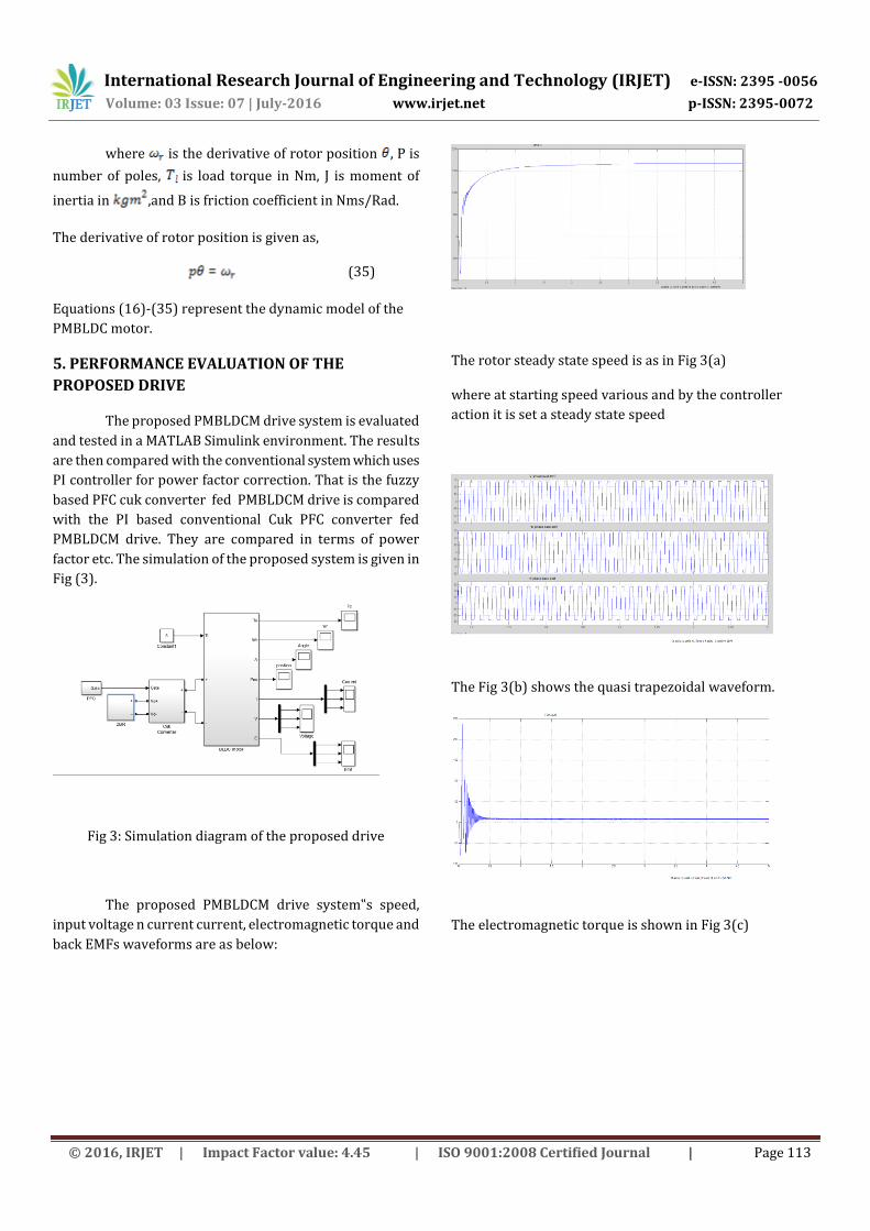
Fig 3: Simulation diagram of the proposed drive
The proposed PMBLDCM drive system‟s speed,
input voltage n current current, electromagnetic torque and
back EMFs waveforms are as below:
The rotor steady state speed is as in Fig 3(a)
where at starting speed various and by the controller
action it is set a steady state speed
The Fig 3(b) shows the quasi trapezoidal waveform.
The electromagnetic torque is shown in Fig 3(c)

International Research Journal of Engineering and Technology (IRJET) e-ISSN: 2395 -0056
Volume: 03 Issue: 07 | July-2016 www.irjet.net p-ISSN: 2395-0072
© 2016, IRJET | Impact Factor value: 4.45 | ISO 9001:2008 Certified Journal | Page 114
The input voltage and current are shown in Fig 3(d)
The proposed drive system is then compared with
the conventional Cuk PFC converter based PMBLDCM drive
in terms of THD to establish that the proposed drive is
efficient over the conventional system. The THD analysis and
power correction is shown in table II
Table -2: Performance Details
TYPE COVENTIONAL
SYSTEM
PROS\POSED
SYSTEM
THD – INPUT
CURRENT (%)
19.53
15.43
POWER
FACTOR
.995
.997
IV. CONCLUSION
A fuzzy based PFC Cuk converter for a PMBLDCM drive has been proposed and validated The PFC converter has ensured reasonable high power factor of the order of 0.997 in wide range of the speed as well as input AC voltage. The THD of AC mains current has been observed well below 19 % in most of the cases .The performance of the drive has been found very good in the wide range of input AC This topology has been found suitable for the applications involving speed control at constant torque load.
REFERENCES
[1] J. F. Gieras and M. Wing, Permanent Magnet Motor
Technology,design and Application. New York: Marcel
Dekker, 2002
[2] N. Mohan, M. Undeland, and W. P. Robbins, Power
Electronics: Converters, Applications and Design.
Hoboken, NJ: Wiley, 1995
[3] Huai Wei, “Comparison of basic converter topologies for
power factor correction” University of central Florida,
Orlando, 1998.
[4] W. Choi, J.Kwon, E. Kim, J. Lee, and B.Kwon, “Bridgeless
boost rectifier with low conduction losses and reduced
diode reverse recovery problems” IEEE Trans. Ind.
Electron., vol. 54, no. 2, pp. 769–780, Apr. 2007
[5] W. Wei, L. Hongpeng, J. Shigong, and X. Dianguo, “A
novelBridgeless buck-boost PFC converter,” in Proc. IEEE
Power Electron, Spec. Conf., 2008, pp. 1304–1308.
[6] Yungtaek Jang, Milan M Jovanovic “Bridgeless High
power factor Buck converter”, IEEE Trans. Power
Electron., vol. 26, no. 2, pp. 291–297, Feb. 2011
[7] M. Mahdavi and H. Farzanehfard, “Bridgeless SEPIC PFC
rectifier withreduced components and conduction
losses,” IEEE Trans. Ind. Electron., vol. 58, no. 9, pp. 4153–
4160, Sep. 2011.
[8] Sebastian, J., Cobos, J.A., Lopera, J.M., and Uceda, J.: „The
determination of boundaries between continuous and
discontinuous conduction mode in PWM DC-to-DC
converters used as power factor pre-regulators‟, IEEE
Trans. Power Electron., 1995, 10, (5)