Embed Size (px)
Citation preview

www.ijatir.org
ISSN 2348–2370
Vol.07,Issue.21,
December-2015,
Pages:4213-4220
Copyright @ 2015 IJATIR. All rights reserved.
Implementation of Fuzzy Logic Controlled Based PFC Cuk Converter Fed
BLDC Motor Drive BODDAPU SURESH
1, DR. N. SAMBA SIVA RAO
2
1PG Scholar, Dept of EEE, NRI Institute of Technology, Agiripalli, Krishna (Dt), AP, India.
2Professor & HOD, Dept of EEE, NRI Institute of Technology, Agiripalli, Krishna (Dt), AP, India.
Abstract: This paper provides the detailed analysis of the
DC-DC chopper fed Brushless DC motor drive used for
low-power applications. The various methods used to
improve the power quality at the ac mains with lesser
number of components are discussed. The most effective
method of power quality improvement is also simulated
using MATLAB/Simulink. It utilizes one control signal
over the whole line cycle. In addition, the proposed
converter exhibits low inrush current and low magnetic
emissions as classical Cuk topology. The partial
elimination of diodes in DBR in the bridgeless topology
results in lower conduction losses as compared with
conventional Cuk converter. The speed of the BLDC motor
is controlled by varying the Dc bus voltage of voltage
source inverter(VSI) which uses a low frequency switching
of VSI (electronic commutation of BLDC motor) for low
switching losses. A diode bridge rectifier (DBR) followed
by a Cuk converter working in discontinuous conduction
mode (DCM) is used for control DC link voltage with
unity power factor at AC mains. The fuzzy based controller
system is used for general purpose industrial applications.
Keywords: CCM, Cuk converter, DCM, PFC, BLDC
Motor, Power Quality, Fuzzy Logic Control.
I. INTRODUCTION
BLDC motors are most popular in household
appliances over the last few decades [1-3]. As the name
indicates, it has no brushes for commutation thus
eliminates the disadvantages of wear and tear in
conventional DC motors. The switches are electronically
commutated with the help of rotor position detected using
hall sensors. Hence the BLDC motor is also known as
electronically commutated motor [4- 5]. Power quality
problems have become important issues in these motors
due to the recommended limits of harmonics in supply
current by various international power quality standards
such as the International Electro technical Commission
(IEC) 61000-3-2 [6]. Combination of motor with inverter
is the BLDC motor setup. BLDC motor is powered with
two level inverter. The two level inverter composed of 6
switches. Based on rotor position obtained from hall
sensors/optical encoders/resolvers, the power electronic
switches are commutated. A BLDC motor when fed by a
diode bridge rectifier (DBR) has higher conduction losses.
The high conduction loss caused by the high forward
voltage drop of the bridge diode begins to degrade the
overall system efficiency. The heat generated within the
bridge rectifier may destroy the individual diodes. Hence,
it becomes necessary to utilize a bridge rectifier with
higher current handling capability or heat dissipating
characteristics.
In this PFC converter a DC-DC converter topology is
mostly used amongst several available topologies with
variations of capacitive/inductive energy transfer (e.g.
boost, buck-boost, Cuk, SEPIC, zeta converters). It results
in an improved performance, such as reduction of AC
mains current harmonics, acoustic noise, electromagnetic
interference (EMI) and improved efficiency, wide input
voltage range utilization etc. This paper deals with an
application of a PFC converter for the speed control of a
PMBLDCMD. For the proposed voltage controlled drive, a
Cuk dc–dc converter is used as a PFC converter because of
its continuous input and output currents, small output filter,
and wide output voltage range as compared to other single
switch converters [10]–[12]. Moreover, apart from PQ
improvement at ac mains, it controls the voltage at dc link
for the desired speed of the Air-Con with the help of
suitable fuzzy logic controller. So an attempt is made to
remove the drawbacks associated with sensored control
[14] and use of traditional controllers by using sensor less
control and fuzzy controller for PMBLDC motor. Thus this
method of sensor less control of PMBLDC will provide
advantages like cost reduction, reliability, elimination of
difficulty in maintaining the sensor etc. and developing
nonlinear system for embedded control. In recent years, the
number and variety of applications of Fuzzy Logic (FL)
have increased significantly.
To understand why use of Fuzzy Logic has grown, it
must be first understood as what is meant by Fuzzy Logic.
Fuzzy Logic has two different meanings. In a narrow
sense, Fuzzy Logic is a logical system, which is an
extension of multivalve logic. However, in a wider sense
Fuzzy Logic is almost synonymous with the theory of
Fuzzy sets, a theory which relates to classes of objects with
un sharp boundaries in which membership is a matter of

BODDAPU SURESH, DR. N. SAMBA SIVA RAO
International Journal of Advanced Technology and Innovative Research
Volume.07, IssueNo.21, December-2015, Pages: 4213-4220
degree. In this perspective, Fuzzy logic in its narrow sense
is a branch of Fuzzy Logic. Even in its more narrow
definition, Fuzzy logic differs both in concept and
substance from traditional multivalve logical systems.
II. SYSTEM CONFIGURATION
Figs.1 and 2 show the PFC Cuk converter based VSI
fed BLDC motor drive using a current multiplier and a
voltage follower approach respectively. A high frequency
metal oxide semiconductor field effect transistor
(MOSFET) is used in Cuk converter for PFC and voltage
control [26-30], where as insulated gate bipolar transistor‟s
(IGBT) are used in the VSI for its low frequency operation.
BLDC motor is commutated electronically to operate the
IGBT‟s of VSI in fundamental frequency switching mode
to reduce its switching losses. The PFC Cuk converter
operating in CCM using a current multiplier approach is
shown in Fig. 1 i.e. the current flowing in the input and
output inductors (L Lo), and the voltage across the
intermediate capacitor (C1) remains continuous in a
switching period.
Fig.1. A BLDC Motor Drive Fed by a PFC Cuk
Converter Using A Current Multiplier Approach With
Fuzzy Logic Controller.
Whereas, Fig.2 shows a Cuk converter fed BLDC motor
drive operating in DCM using a voltage follower
Approach. The current flowing in either of the input or
output inductor (Li and Lo) or the voltage across the
intermediate capacitor (C1) become discontinuous in a
switching period [31, 32] for a PFC Cuk converter
operating in DCM. A Cuk converter is designed to operate
in all three discontinuous conduction modes and a
continuous conduction mode of operation and its
performance is evaluated for a wide voltage control with
unity power factor at AC mains.
III. OPERATION OF CUK CONVERTER IN
DIFFERENT MODES
The operation of Cuk converter is studied in four
different modes of CCM and DCM. In CCM, the current in
inductors (Li and Lo) and voltage across intermediate
capacitor C1 remain continuous in a switching period [33].
Moreover, the DCM operation is further classified into two
broad categories of discontinuous inductor current mode
(DICM) and discontinuous capacitor voltage mode
(DCVM). In DICM, the current flowing in inductor Li or
Lo becomes discontinuous in their respective modes of
operation [31, 32]. While in DCVM operation, the voltage
appearing across the intermediate capacitor C1becomes
discontinuous in a switching period [34, 35]. Different
modes for operation of CCM and DCM are discussed as
follows.
A. CCM Operation
The operation of Cuk converter in CCM is described as
follows. Figs.3 (a) and (b) show the operation of Cuk
Fig.2. A BLDC Motor Drive Fed by a PFC Cuk
Converter Using a Voltage Follower Approach.
Converter in two different intervals of a switching period
and Fig.3(c) shows the associated waveforms in a complete
switching period. Interval I: When switch Swim turned on,
inductor LI stores energy while capacitor C1discharges and
transfers its energy to DC link capacitor Cd as shown in
Fig.3 (a). Input inductor current iLi increases while the
voltage across the intermediate capacitor VC1 decreases as
shown in Fig.3(c). Interval II: When switch Swiss turned
off, then the energy stored in inductor Lo is transferred to
DC link capacitor Cd, and inductor Li transfers its stored
energy to the intermediate capacitor C1 as shown in Fig.3
(b). The designed values of Li, Lo and C1 are large enough
such that a finite amount of energy is always stored in
these components in a switching period.
B. DICM (Li) Operation
The operation of Cuk converter in DICM (Li) is
described as follows. Figs.4(a)-(c) show the operation of
Cuk converter in three different intervals of a switching
period and Fig.4(d) shows the associated waveforms in a
switching period. Interval I: When switch Swim turned on,
inductor Li stores energy while capacitor C1 discharges
through Switch Sw to transfers its energy to the DC link
capacitor Cd as shown in Fig.4 (a). Input inductor current

Implementation of Fuzzy Logic Controlled Based PFC Cuk Converter Fed BLDC Motor Drive
International Journal of Advanced Technology and Innovative Research
Volume.07, IssueNo.21, December-2015, Pages: 4213-4220
iLi increases while the voltage across the capacitor C1
decreases as shown in Fig.4 (d). Interval II: When switch
Swiss turned off, then the energy stored in inductor Li is
transferred to intermediate capacitor C1 via diode D, till it
is completely discharged to enter DCM operation.
Interval III: During this interval, no energy is left in input
inductor Li, hence current I Latecomers zero. Moreover,
inductor cooperates in continuous conduction to transfer its
energy to DC link capacitor Cd.
C. DICM (Lo) Operation
The operation of Cuk converter in DICM (Lo) is
described as follows. Figs.5(a)-(c) show the operation of
Cuk converter in three different intervals of a switching
period and Fig.5(d) shows the associated waveforms in a
switching period. Interval I: As shown in Fig.5(a), when
switch Swim turned on, inductor L stores energy while
capacitor C1 discharges through switch Sw to transfer its
energy to the DC link capacitor Cd. Interval II: When
switch Swiss turned off, then the energy stored in inductor
Li and Lo is transferred to intermediate capacitor C1and DC
link capacitor Cd respectively. Interval III: In this mode of
operation, the output inductor Lo is completely discharged
hence its current iLo becomes zero. An inductor Li operates
in continuous conduction to transfer its energy to the
intermediate capacitor C1 via diode D.
D. DCVM (C1) Operation
The operation of Cuk converter in DCVM (C1) is
described as follows. Figs.6(a)-(c) show the operation of
Cuk converter in three different intervals of a switching
period and Fig. 6(d) shows the associated waveforms in a
switching period. Interval I: When switch Swim turned on
as shown in Fig.6 inductor L Is tares energy while capacitor
C1discharges through switch Sw to transfer its energy to the
DC link capacitor Cd as shown in Fig.6 (d). Interval II:
The switch is in conduction state but intermediate capacitor
C1is completely discharged, hence the voltage across it
becomes zero. Output inductor Lo continues to supply
energy to the DC link capacitor. Interval III: As the switch
Sw is turned off, input inductor LI starts charging the
intermediate capacitor, while the output inductor Lo
continues to operate in continuous conduction and
supplies energy to the DC link capacitor.
Fig.3. Operation of Cuk converter in CCM during (a-b)
different intervals of switching period and (c) the
associated waveforms.
IV. DESIGN OF A PFC CUK CONVERTER
A PFC based Cuk converter fed BLDC motor drive is
designed for DC link voltage control of VSI with power
factor correction at the AC mains. The Cuk converter is
designed for a CCM and three different DCMs. In DCM,
any one of the energy storing elements Li, Lo or C1are
allowed to operate in discontinuous mode whereas in
CCM, all these three parameters operate in continuous
conduction. The design and selection criterion of these
three parameters is discussed in the following section. The
input voltage Vs applied to the DBR is given as,
(1)
Where Vm is the peak input voltage (i.e. √2Vs, Vs is the
rms value of supply voltage), fL is the line frequency i.e. 50
Hz. The instantaneous voltage appearing after the DBR is
as,
(2)
Where | | represents the modulus function. The output
voltage, Vdc of Cuk converter is given as
(3)
Where D represents the duty ratio. The instantaneous
value of duty ratio, D(t) depends on the Input voltage
appearing after DBR, Vin (t) and the required DC link
voltage, Vdc.
BODDAPU SURESH, DR. N. SAMBA SIVA RAO
International Journal of Advanced Technology and Innovative Research
Volume.07, IssueNo.21, December-2015, Pages: 4213-4220
Fig. 4. Operation of Cuk converter in DICM (Li)
during (a-c) different Intervals of switching period and
(d) the associated waveforms.
Hence the instantaneous duty ratio, D (t) is obtained by
substituting (2) in (3) and rearranging it as,
(4)
The Cuk converter is designed to operate from a
minimum DC voltage of 40V (Vdc min) to a maximum DC
link voltage of 200V (Vdc max). The PFC converter of
maximum power rating of 350W (P max) is designed for a
BLDC motor of 251W (Pm) (full specifications given in
Table I) and the switching frequency (fS) is taken as
20kHz. Since the speed of the BLDC motor is controlled
by varying the DC link voltage of the VSI, hence the
instantaneous power, Piatt any DC link voltage (Vdc) can
be taken as linear function of Vdc. Hence for a minimum
value of DC link voltage as 40V, the minimum power is
calculated as 70W.
A. Design of Li
For Continuous or Discontinuous Current Conduction
the critical value of input inductor Lice is expressed as
(5)
Hence the critical value of input side inductor is directly
proportional to the rams value of supply voltage; therefore
the worst case design occurs for the minimum value of
supply voltage (i.e. Vs=Vs min =85V). Now the critical
value of input inductor at the maximum DC link voltages
of 200V at the peak value of supply voltage (i.e. √2Vsmin)
is calculated as,
(6)
Fig.5. Operation of Cuk converter in DICM (Lo)
during (a-c) different intervals of switching period and
(d) the associated waveforms.
And the critical value of input inductor at the minimum
value of DC link voltages of 40V at the peak value of
supply voltage is calculated as
(7)
Hence the value of critical input inductance is obtained
lower at maximum DC link voltage. Therefore, the critical
value of input inductor is selected lower than Lic200. The
Performance of the Cuk converter feeding BLDC motor
drive is analyzed for different values of input side inductor
i.e.
Fig.6. Operation of Cuk converter in DCVM (C1)
during (a-c) different intervals of switching period and
(d) the associated waveforms.
Implementation of Fuzzy Logic Controlled Based PFC Cuk Converter Fed BLDC Motor Drive
International Journal of Advanced Technology and Innovative Research
Volume.07, IssueNo.21, December-2015, Pages: 4213-4220
A high THD of AC mains current is obtained at higher
values of input side inductor which doesn‟t comply with
the IEC 61000-3-2 [14]. Hence the input inductor (Li) of
the order of 100µH is selected for its operation in
discontinuous conduction to achieve a low value of THD
of supply current at AC mains. The value of input inductor
to operate in CCM is decided by the amount of permitted
ripple current (η) and is as [17],
(8)
The maximum inductor ripple current is obtained at
the rated condition i.e. Vdc=200V for a minimum supply
voltage (Vs min =85V). Hence the input side inductor is
designed at the peak value of minimum supply voltage (i.e.
Vs=√2Vsmin) as,
(9)
Where the permitted amount of ripple current is selected as
25% of the input current. Hence the input side inductor of
2.5mH is selected for its operation in continuous
conduction.
V. FUZZY LOGIC CONTROL
L. A. Zadeh presented the first paper on fuzzy set
theory in 1965. Since then, a new language was developed
to describe the fuzzy properties of reality, which are very
difficult and sometime even impossible to be described
using conventional methods. Fuzzy set theory has been
widely used in the control area with some application to
power system [5]. A simple fuzzy logic control is built up
by a group of rules based on the human knowledge of
system behavior. Matlab/Simulink simulation model is
built to study the dynamic behavior of converter.
Furthermore, design of fuzzy logic controller can provide
desirable both small signal and large signal dynamic
performance at same time, which is not possible with linear
control technique. Thus, fuzzy logic controller has been
potential ability to improve the robustness of compensator.
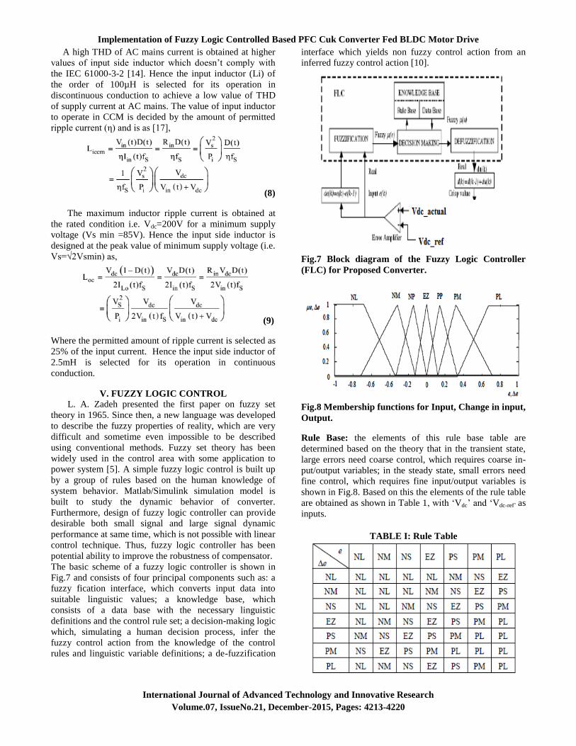
The basic scheme of a fuzzy logic controller is shown in
Fig.7 and consists of four principal components such as: a
fuzzy fication interface, which converts input data into
suitable linguistic values; a knowledge base, which
consists of a data base with the necessary linguistic
definitions and the control rule set; a decision-making logic
which, simulating a human decision process, infer the
fuzzy control action from the knowledge of the control
rules and linguistic variable definitions; a de-fuzzification
interface which yields non fuzzy control action from an
inferred fuzzy control action [10].
Fig.7 Block diagram of the Fuzzy Logic Controller
(FLC) for Proposed Converter.
Fig.8 Membership functions for Input, Change in input,
Output.
Rule Base: the elements of this rule base table are
determined based on the theory that in the transient state,
large errors need coarse control, which requires coarse in-
put/output variables; in the steady state, small errors need
fine control, which requires fine input/output variables is
shown in Fig.8. Based on this the elements of the rule table
are obtained as shown in Table 1, with „Vdc‟ and „Vdc-ref‟ as
inputs.
TABLE I: Rule Table

BODDAPU SURESH, DR. N. SAMBA SIVA RAO
International Journal of Advanced Technology and Innovative Research
Volume.07, IssueNo.21, December-2015, Pages: 4213-4220
VI. MATLAB/SIMULINK RESULTS
Simulation results of this paper is as shown in bellow
Figs.9 to 20.
Fig.9.Matlab/Simulink Model of A BLDC Motor Drive
Fed by a PFC Cuk Converter with PI Controller.
Fig.10.Simulated waveform Source Voltage and
Current DC Voltage, Speed, Torque, Armature
Current of BLDC motor drive with Cuk converter
operating in CCM.
Fig.11.Simulation Waveform of Switch Voltage and
Current, Inductor Current, Load Current and
Capacitor Voltage of BLDC Motor Drive with Cuk
Converter Operating in CCM.
Fig.12.Simulated waveform Source Voltage and
Current DC Voltage, Speed, Torque, Armature
Current of BLDC motor drive with Cuk Converter
Operating in DICM (Li).
Fig.13.Simulation Waveform of Switch Voltage and
Current, Inductor Current, Load Current and
Capacitor Voltage of BLDC motor drive with Cuk
Converter Operating in DICM (Li).
Fig.14.Simulated waveform Source Voltage and
Current DC Voltage, Speed, Torque, Armature
Current of BLDC motor drive with Cuk Converter
Operating in DICM (Lo).

Implementation of Fuzzy Logic Controlled Based PFC Cuk Converter Fed BLDC Motor Drive
International Journal of Advanced Technology and Innovative Research
Volume.07, IssueNo.21, December-2015, Pages: 4213-4220
Fig.15.Simulation Waveform of Switch Voltage and
Current, Inductor Current, Load Current and
Capacitor Voltage of BLDC motor drive with Cuk
converter operating in DICM (Lo).
Fig.16.Simulated waveform Source Voltage and
Current DC Voltage, Speed, Torque, Armature
Current of BLDC motor drive with Cuk converter
operating in DCVM.
Fig.17.Simulation Waveform of Switch Voltage and
Current, Inductor Current, Load Current and
Capacitor Voltage of BLDC motor drive with Cuk
converter operating in DCVM.
Fig.18.THD for Source Current with PI Controller.
Fig.19.Matlab/Simulink model of A BLDC Motor Drive
Fed by a PFC Cuk Converter with Fuzzy Logic
Controller.
Fig.20.THD for Source Current with Fuzzy Logic
Controller.
BODDAPU SURESH, DR. N. SAMBA SIVA RAO
International Journal of Advanced Technology and Innovative Research
Volume.07, IssueNo.21, December-2015, Pages: 4213-4220
VII. CONCLUSION
The speed of the BLDC motor drive has been controlled
by varying the DC link voltage of VSI; which allows the
VSI to operate in fundamental frequency switching mode
for reduced switching losses. Four different modes of Cuk
converter operating in CCM and DCM have been explored
for the development of BLDC motor drive with unity
power factor at AC mains. A detailed comparison of all
modes of operation has been presented on the basis of
feasibility in design and the cost constraint in the
development of such drive for low power applications. The
proposed drive system has shown satisfactory results in all
aspects and is a recommended solution for low power
BLDC motor drives. Moreover, voltage and current
stresses on the fuzzy based PFC switch have been
evaluated for determining the practical application of the
proposed scheme. The proposed drive has been developed
to validate the performance of the proposed BLDC motor
drive under speed control with improved power quality at
ac mains. The proposed scheme has shown satisfactory
performance, and it is a recommended solution applicable
to low-power BLDC motor drives.
VIII. REFERENCES
[1] J. F. Gieras and M. Wing, Permanent Magnet Motor
Technology- Design and Application, Marcel Dekker Inc.,
New York, 2002.
[2] C. L. Xia, Permanent Magnet Brushless DC Motor
Drives and Controls, Wiley Press, Beijing, 2012.
[3] Y. Chen, Y, C. Chiu, C, Y. Jhang, Z. Tang and R.
Liang, “A Driver for the Single-Phase Brushless DC Fan
Motor with Hybrid Winding Structure,” IEEE Trans. Ind.
Electron., Early Access,2012.
[4] S. Nikam, V. Rallabandi and B. Fernandez, “A high
torque density permanent magnet free motor for in-wheel
electric vehicle application,” IEEE Trans. Ind. Appl., Early
Access, 2012.
[5] X. Huang, A. Goodman, C. Gelada, Y. Fang and Q.
Lu, “A Single Sided Matrix Converter Drive for a
Brushless DC Motor in Aerospace Applications,” IEEE
Trans. Ind. Electron., vol.59, no.9, pp.3542-3552, Sept.
2012.
[6] W. Cui, Y. Gong and M. H. Xu, “A Permanent Magnet
Brushless DC Motor With Bifilar Winding for Automotive
Engine Cooling Application,” IEEE Trans. Magnetics,
vol.48, no.11, pp.3348-3351, Nov. 2012.
[7] C. C. Hwang, P. L. Li, C. T. Liu and C. Chen, C,
“Design and analysis of a brushless DC motor for
applications in robotics,” IET Elect. Pow. Appl.,vol.6,
no.7,pp.385-389,August 2012.
[8] T. K. A. Brekken, H. M. Hapke, C. Stillinger and J.
Prudell, “Machines and Drives Comparison for Low-
Power Renewable Energy and Oscillating Applications,”
IEEE Trans. Energy Convers., vol.25, no.4, pp.1162-1170,
Dec. 2010.
[9] N. Milivojevic, M. Krishnamurthy, A. Emadi and I.
Stamenkovic,“Theory and Implementation of a Simple
Digital Control Strategy for Brushless DC Generators,"
IEEE Trans. Power Electron., vol.26, no.11, pp.3345-
3356, Nov. 2011
[10] T. Kenjo and S. Nagamori, Permanent Magnet
Brushless DC Motors, Clarendon Press, Oxford, 1985.
[11]J. R. Handershot and T.J.E Miller, Design of Brushless
Permanent Magnet Motors, Clarendon Press, Oxford,
2010.
[12]T. J. Sokira and W. Jaffe, Brushless DC Motors:
Electronic Commutation and Control, Tab Books, USA,
1989.
[13] H. A. Toliyat and S. Campbell, DSP-based Electro-
mechanical Motion Control, CRC Press, New York, 2004.
[14] Limits for Harmonic Current Emissions (Equipment
input current ≤16 A per phase), International Standard IEC
61000-3-2, 2000.
[15] N. Mohan, T. M. Undeland and W. P. Robbins, Power
Electronics: Converters, Applications and Design, John
Wiley and Sons Inc, USA, 2009.