Embed Size (px)
Citation preview

Pertanika J. Sci. & Technol. 25 (3): 949 - 962 (2017)
SCIENCE & TECHNOLOGYJournal homepage: http://www.pertanika.upm.edu.my/
ISSN: 0128-7680 © 2017 Universiti Putra Malaysia Press.
Article history:Received: 11 January 2017Accepted: 21 April 2017
E-mail addresses: [email protected] (Melvin Paious), [email protected] (Raviraja Adhikari),[email protected] (Nagaraja)*Corresponding Author
Investigation on Tapping of Al6061-SiC Metal Matrix Composite with HSS Taps
Melvin Paious1, Raviraja Adhikari2 and Nagaraja2*1Department of Mechanical Engineering, Saint Thomas College of Engineering and Technology, Kannur, Kerala State 700027, India 2Department of Mechanical and Manufacturing Engineering, Manipal Institute of Technology, Manipal University, Karnataka State, 576104 India
ABSTRACT
The present study deals with tapping of Al6061/SiC metal matrix composite. Stir casting technique was used for the fabrication of composite. Castings were produced by varying weight percentage of SiC (5, 7.5 and 10 wt. %) of 23 μm size in Al6061. The fabricated specimens were characterized for their hardness and tensile strength. It was found that hardness increases by the addition of SiC. Images from Scanning Electron Microscope (SEM) and metallurgical microscope showed the fair distribution of reinforcement. Due to the presence of SiC reinforcement that is highly abrasive in nature makes machining difficult and produces high rate of tool wear. After drilling, tapping experiments were conducted for the machinability study of Al6061/SiC metal matrix composite by using M8 HSS machine tap. Tapping operation was performed under dry condition with different cutting speed (12, 14 and 16 m/min) and constant feed rate equal to the pitch of thread. Torque required for tapping was measured using strain gauge based two-component cutting tool dynamometer. Microstructure and surface morphology of thread surfaces was analyzed using Metallurgical Microscope and Scanning Electron Microscope (SEM) respectively. Estimation of progressive flank wear of machine taps was undertaken using profile projector. The performance of HSS machine taps was evaluated in terms of tapping torque, tool flank wear and surface characteristics of thread surfaces.
Keywords: Al6061, flank wear, machine tap, metal matrix composite, stir casting, tapping
INTRODUCTION
Aluminium based composites are increasingly being used in the transport, aerospace, marine, automobile industries, owing to their improved strength, stiffness and wear resistance properties. The widely used reinforcing materials for these composites

Melvin Paious, Raviraja Adhikari and Nagaraja
950 Pertanika J. Sci. & Technol. 25 (3): 949 - 962 (2017)
are silicon carbide, aluminium oxide and graphite in the form of particles or whiskers (Kumar, Rao, Selvaraj & Bhagyashekar, 2010). Stir casting is the most economical, flexible and easy method to prepare aluminium silicon carbide metal matrix composite. It involves melting of the matrix material, followed by introducing reinforcement material into the melt, obtaining a suitable dispersion through stirring (Soltani et al., 2015).
Metal matrix composite materials are one of the most difficult to machine due to their inherent inhomogeneity, abrasive nature of reinforcements and anisotropic nature resulting in high tool wear and subsurface damage. The extensive tool wear is caused by the very hard and abrasive reinforcements (Wilson & Harvey, 1959). The main reason for wear is the direct contact between the reinforcing particles and the cutting edge which causes both a mechanical and a thermal load on the cutting edge (Kilickap, Cakir, Aksoy & Inan, 2005). The dominant wear mechanism is abrasion generated by impacts at the cutting edge and by the sliding motion of the particles relative to the rake and clearance face. Additionally, thermal load stresses the cutting edge. This thermal load results from hot spots which are generated by micro contacts between the cutting edge and the reinforcement.
Figure 1. Schematic diagram of stir casting setup (Chawla & Chawla, 2006)
From previous studies it can be discerned that the reinforcement material, type of reinforcement, weight percentage of the reinforcement and matrix properties as well as the distribution of these particles in the matrix are the factors that affect the overall machinability of these composites (Hung, Boey, Khor, Phua & Lee, 1996). Cutting speed, feed and depth of cut have a similar effect on tool life and surface finish in machining of metal matrix composites (Sahoo, Pradhan & Rout, 2013).
The reinforced particles tend to dislodge themselves from the matrix and roll in front of the cutting edge, to plough through the machined surface and generating grooves on it (Sekhar & Singh, 2015) The tool life decreases while the surface finish improves only slightly with an increase in cutting speed, since the tool temperature increases with cutting speed, thereby softening the tool material.
A tap is simply a hardened steel screw with lengthwise grooves, called flutes, milled or ground across the threads. In a machine tap, flutes form a series of teeth and provide chip room along the entire length of the threaded portion of the tap.

Investigation on Tapping of Al6061-SiC MMC with HSS Taps
951Pertanika J. Sci. & Technol. 25 (3): 949 - 962 (2017)
When a tap is turned into a hole of proper diameter, the teeth cut into the wall of the hole and remove material to form threads of the same pitch as the threads found in the tap. The majority of tapping process is done by the teeth on the chamfer portion and the first full following thread (Drozda & Wick, 1983).
The common failures of tapping are tap breakage and poor thread quality. From the metallurgical point of view, the shape of a tap causes very high surface stress concentrations as it is subjected to both torsional and bending loads (Sha & Wu,1990). Generally, tap breakage may be caused by overload, material fatigue, inadequate heat treatment etc. The quality of the thread is decided by the size and surface finish. The threaded hole may be undersized or oversized. In a threading operation, surface finish is usually not crucial, if the thread is to be used for a fastener. But, the burr on the entry or exit of the hole can cause a significant problem. The major causes of the above symptoms are tap wear, error in size of hole, misalignment, and poor lubrication. Information available on the tapping of metal matrix composite is very rare and incomplete.
Extensive research work has been done on turning and drilling of Al6061/SiC metal matrix composite. However, there has been little attempt on studies involving tapping of Al6061/SiC metal matrix composite. Therefore, it is essential to create more knowledge about tapping on Al6061/SiC metal matrix composite. The aim of the present study is to bring out the influence of varying percentage of presence of SiC in the matrix, cutting speed on tool wear and surface roughness of the threaded hole.
METHOD
Fabrication of Specimens
The matrix material selected for the present studies was Al6061 alloy and was procured from HINDALCO Industries Limited, India. The chemical composition of Al6061 alloy, as provided by the supplier is given in Table 1.
Silicon carbide particles of size 23 microns was used as reinforcement material having properties such as high hardness and strength, chemical and thermal stability, high melting point, oxidation resistance and high erosion resistance.
The schematic diagram of the setup used for fabrication of metal matrix composite is shown in Figure 1. Al6061 rods were melted at a temperature of 800oC using an electric furnace. Preheating of silicon carbide particles was done at 600oC for an hour to remove the moisture and gases from the surface of the particulates. The aluminium melt is degassed at a temperature of 750oC using nitrogen gas. Degassing eliminates a variety of impurities which could pose serious problems in the production of quality castings. At the forefront of these impurities is hydrogen. The solubility of hydrogen in molten aluminium increases with temperature. Solidifying metal must reject the hydrogen. Otherwise resultant castings will suffer from porosity. To increase the wettability of the silicon carbide particles in the matrix material, 2 wt. % magnesium ribbons was added to the molten metal. Stirring of molten metal with SiC particles added slowly was done for 10 minutes.
Melvin Paious, Raviraja Adhikari and Nagaraja
952 Pertanika J. Sci. & Technol. 25 (3): 949 - 962 (2017)
Table 1 Chemical composition of Al6061
Contents Weight PercentageAl 97.547Si 0.773Fe 0.22Mn 0.068Mg 0.922Cu 0.276Ti 0.22Cr 0.072
CHARECTERISATION OF SPECIMENS
Vickers Hardness and Tensile Test
Specimens for Vicker’s hardness test were prepared from round castings by turning and polishing with different grades of abrasive paper. Hardness test was carried out using Micro Vicker’s Hardness Tester (Matzusawa make). Five sample points was taken for averaging the hardness test value. The tensile test specimens were prepared according to ASTM E8/E8M-11 standard, as shown in the Figure 2. The tensile test was performed on an electronic tensometer.
A= 36 mm, D = 6 mm, G = 30 mm, R = 6 mm
Figure 2. Tensile test specimen
Micro Structure and Surface Morphology
The microstructure plays an important role in the overall performance of a composite and the physical properties depend on the microstructure, reinforcement particle size, shape and distribution in the alloy. Microstructure study of the composites was done using Trinocular Inverted Metallurgical Microscope. The surface morphology of the work materials was captured by using EVO MA18 Scanning Electron Microscope (SEM).

Investigation on Tapping of Al6061-SiC MMC with HSS Taps
953Pertanika J. Sci. & Technol. 25 (3): 949 - 962 (2017)
EXPERIMENTATION
Setup
The tapping experiments were conducted on Computer Numerical control (CNC) vertical machining centre (M/s Ace Manufacturing Systems, Bangalore, India) at constant feed rate of 1.25 mm/rev (pitch of thread) with speeds 12, 14 and 16 m/min. The material behavior of Al6061/SiC composite was expected to be in between aluminium alloy and cast iron. The cutting speed for the tapping operation was selected between the tapping speed for cast iron (9-12m/min) and aluminium (19-22 m/min) (C. M. T. I., 1987). High Speed Steel (HSS) machine taps M8X1.25 with three flutes was used for tapping operation. Before tapping, the specimens were pre-drilled with 6.8 mm diameter drill bit. Figure 3 shows the arrangement used for conducting tapping experiments on composites.
Figure 3. Arrangement used for conducting tapping experiments on composites
A strain gauge based Drill tool dynamometer (IEICOS, Bangalore, India) was used for measuring thrust force and torque produced on the work piece during the tapping operation. IEICOS digital multi component force indicator which comprises digital displays calibrated for force and torque measurement with two component drill tool dynamometer was used for measuring the values.
Measurement of Flank Wear
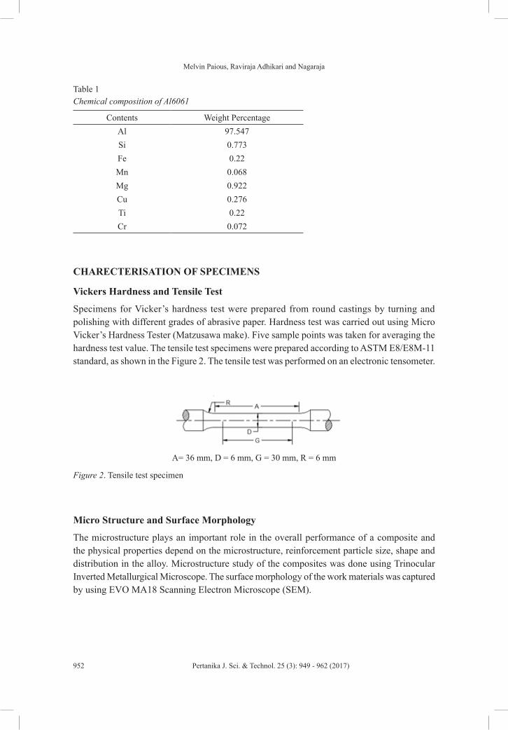
The wear pattern of the machine tap was obtained using a Profile Projector (METZER, India) with a magnification of 20X. The profile of the tap before and after tapping was compared for variations in the profile. The reduction in the height of cutting tooth (h) in the chamfer section is used as a measure of flank wear, as shown in Figure 4.
Melvin Paious, Raviraja Adhikari and Nagaraja
954 Pertanika J. Sci. & Technol. 25 (3): 949 - 962 (2017)
Figure 4. Profile of the chamfer portion of tap
Measurement of Surface Roughness
Surface roughness of the thread surface of tapped hole (hole no: 1,13,26,38 and 51) for all composites (5 wt. %,7.5 wt. % and 10 wt. % of SiC) was measured using Surtronic 3+ surface roughness measuring instrument. For surface roughness test, sampling length of 0.25 mm and average of 3 readings was taken.
Surface Morphology and Microstructure Analysis of Machine Tap and Tapped Hoe Surface
Microstructures of thread surface were taken from the Trinocular Inverted Metallurgical Microscope. The surface morphology of the thread surface was captured by using EVO MA18 (Zeiss) Scanning Electron Microscope (SEM). Thread surface analysis will reveal information such as, effect of tool wear and flow of work piece material during tapping on the thread surface.
RESULTS AND DISCUSSIONS
Hardness Test
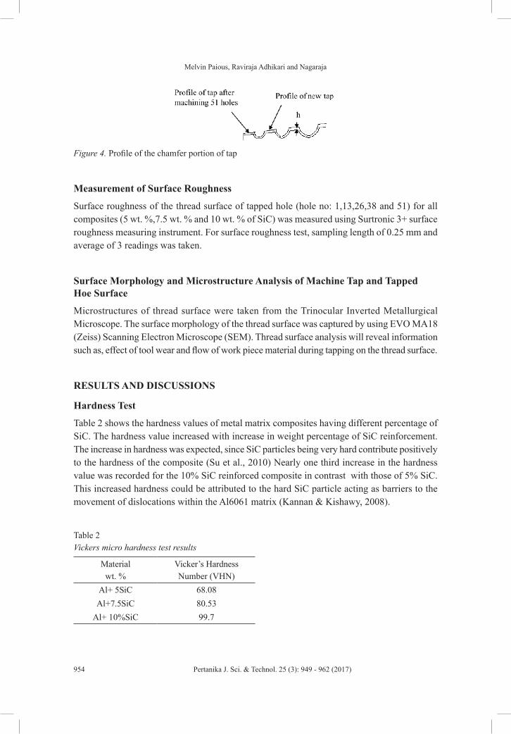
Table 2 shows the hardness values of metal matrix composites having different percentage of SiC. The hardness value increased with increase in weight percentage of SiC reinforcement. The increase in hardness was expected, since SiC particles being very hard contribute positively to the hardness of the composite (Su et al., 2010) Nearly one third increase in the hardness value was recorded for the 10% SiC reinforced composite in contrast with those of 5% SiC. This increased hardness could be attributed to the hard SiC particle acting as barriers to the movement of dislocations within the Al6061 matrix (Kannan & Kishawy, 2008).
Table 2Vickers micro hardness test results
Materialwt. %
Vicker’s HardnessNumber (VHN)
Al+ 5SiC 68.08Al+7.5SiC 80.53
Al+ 10%SiC 99.7
Investigation on Tapping of Al6061-SiC MMC with HSS Taps
955Pertanika J. Sci. & Technol. 25 (3): 949 - 962 (2017)
Tensile Test
From Table 3, it was observed that the ultimate tensile strength (UTS) measured using a tensometer (Khudal Instruments, Pune, India) increased with the addition of SiC. This increase in UTS may be due to the increased presence of SiC particle that acting as barriers to dislocation in microstructure (Kannan & Kishawy, 2008).
Table 3 Tensile test results
MaterialWt. %
Avg. Ultimate TensileStrength(MPa)
(Standard:ASTME08)Al+ 5SiC 113.25Al+7.5SiC 135.6Al+ 10SiC 151.32
Surface Morphology and Microstructure Analysis of Composite
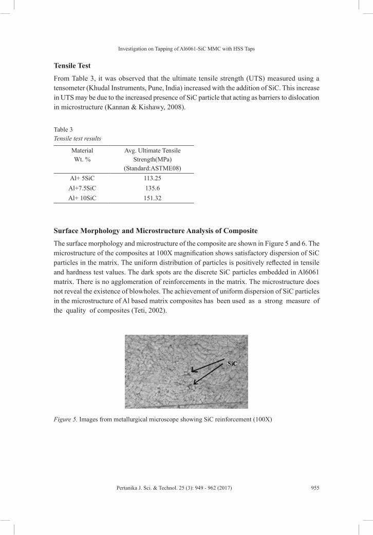
The surface morphology and microstructure of the composite are shown in Figure 5 and 6. The microstructure of the composites at 100X magnification shows satisfactory dispersion of SiC particles in the matrix. The uniform distribution of particles is positively reflected in tensile and hardness test values. The dark spots are the discrete SiC particles embedded in Al6061 matrix. There is no agglomeration of reinforcements in the matrix. The microstructure does not reveal the existence of blowholes. The achievement of uniform dispersion of SiC particles in the microstructure of Al based matrix composites has been used as a strong measure of the quality of composites (Teti, 2002).
Figure 5. Images from metallurgical microscope showing SiC reinforcement (100X)

Melvin Paious, Raviraja Adhikari and Nagaraja
956 Pertanika J. Sci. & Technol. 25 (3): 949 - 962 (2017)
Figure 6. SEM image of Al6061-SiC metal matrix composite with (a) 5%SiC (b) 7.5%SiC (c) 10% SiC (400X)
Flank Wear
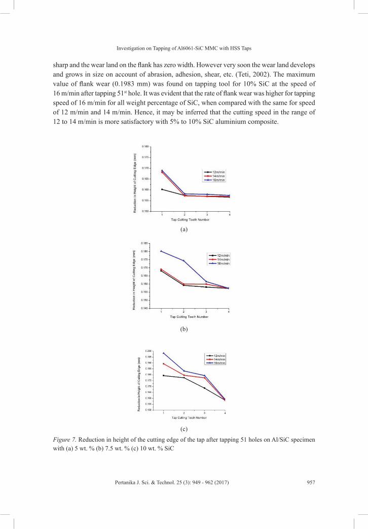
From Figure 7, it was observed that increase in weight percentage of SiC in Al/SiC composite increased the tool wear. Increase in percentage of SiC increased the hardness of the composite and hence tool’s wear. For a particular percentage of SiC particles it was observed that increases in speed increased the flank wear. Since abrasion is expected to be the major form of tool wear when cutting hard particle reinforced aluminium matrix composites, the important factors affecting tool life are the hardness, weight percentage of reinforcement particles in the composites and the speed of machining.
It was also observed that the flank wear increased with increase in the number of holes tapped. As tapping of holes progressed, tapping tool lost its sharpness of cutting edge and became dull. To perform tapping of holes further using the same tool needs higher magnitude of energy. This would induce cascading effect on the rate of tool wear. Therefore, there would be a significant progressive wear of tool with the increase in number of holes.
Flank wear results in reduction of relief angle on the clearance face of the tool. This gives rise to increased frictional resistance. It produces wear land on the side and end flanks of the tool, on account of the rubbing action of the machined surface. In the beginning, the tool is
Investigation on Tapping of Al6061-SiC MMC with HSS Taps
957Pertanika J. Sci. & Technol. 25 (3): 949 - 962 (2017)
sharp and the wear land on the flank has zero width. However very soon the wear land develops and grows in size on account of abrasion, adhesion, shear, etc. (Teti, 2002). The maximum value of flank wear (0.1983 mm) was found on tapping tool for 10% SiC at the speed of 16 m/min after tapping 51st hole. It was evident that the rate of flank wear was higher for tapping speed of 16 m/min for all weight percentage of SiC, when compared with the same for speed of 12 m/min and 14 m/min. Hence, it may be inferred that the cutting speed in the range of 12 to 14 m/min is more satisfactory with 5% to 10% SiC aluminium composite.
(a)
(b)
(c)
Figure 7. Reduction in height of the cutting edge of the tap after tapping 51 holes on Al/SiC specimen with (a) 5 wt. % (b) 7.5 wt. % (c) 10 wt. % SiC

Melvin Paious, Raviraja Adhikari and Nagaraja
958 Pertanika J. Sci. & Technol. 25 (3): 949 - 962 (2017)
From the microscopic image (Figure 8), the area on the flank that has undergone wear can be seen. The increased torque at higher tapping speed and higher weight percentage of SiC indicated the higher energy used during the tapping operation. This also indicated the increases in flank wear at higher tapping speed and weight percentage of SiC.
Figure 8. Image of (100X) tool flank after machining 51 holes on 10% SiC MMC at speed of 16 m/min
Figure 9 shows the sticking of aluminium between the cutting edges of the teeth and flute of the tap. The material stuck on the flute surface of the tool would obstruct the smooth passage of chips, leading to clogging of flute and cutting edges of tap. This would create artificial cutting edges inferior to actual cutting edges, producing poor quality of threads (Steininger, Siller, & Bleicher, 2015)
Figure 9. Aluminium stuck between the cutting edges of the tap
Torque
It was observed that increase in weight percentage of SiC particles increased the torque during machining. There was a significant increase in hardness and strength of the composite while increasing weight percentage of SiC. This could be attributed as one of the main reasons for the increase in torque. It was observed that, at tapping on a specimen with 5 wt. % SiC at 16 m/min, the torque was 15 Nm while it was the same with 10 wt. %SiC was 27.4 Nm.
It was also observed that for a particular percentage of SiC in composite, higher the speed, higher is the torque required. Increase in speed produces more flank wear on cutting edges

Investigation on Tapping of Al6061-SiC MMC with HSS Taps
959Pertanika J. Sci. & Technol. 25 (3): 949 - 962 (2017)
which could cause consumption of more energy during the tapping process resulting in higher magnitude of torque. It was observed that at tapping on a specimen with 10 wt. % SiC at 12 m/min, the torque was 4 Nm while the same with 14m/min was 19 Nm.
It was found the torque required increased with increase in the number of holes tapped as the tool loses its sharpness and becomes dull from progressive wear. A few deviations from this trend was observed when reinforcing particles in the composite were not uniform, resulting from lack of or absence of particles in the region of tapping of specified holes.
Surface Roughness Measurement
From the results, it was evident that for a particular weight percentage of SiC, the surface roughness value of the machined thread surface increases as speed increases. At 5 wt. % SiC, and speed of 12 m/min, the surface roughness value of the threaded surface of the hole was 6.68 μm while the same for 16 m/min was 6.8 μm. It was also observed that increase in speed increases the flank wear on the tool. Flank wear affects the geometry and cutting action of the tool. This would lead to the poor surface finish of the tapped hole. It was also noticed that the surface roughness of the thread surface increased with increase in weight percentage of SiC in metal matrix composite. At 5 wt. % SiC, and speed of 16 m/min, the surface roughness value of the threaded surface of the hole was 6.8 μm while the same for 10 wt. % SiC was 8.8 μm. Hard reinforcing particles in the matrix of composites would not get sheared off when they come across the cutting edge of the tool. They would either remain embedded to the surface or get dislodged from the surface creating dents on the threaded surface. In either of these cases, the quality of thread surface is affected due to the increase in surface roughness.
It was observed that the surface roughness of the tapped hole increased progressively with the increase in number of holes at all speeds and weight percentages of SiC particles. The magnitude and rate of flank wear of the tapping tool increased with increase in speed and weight percentage of SiC. The progressively damaged portions of the cutting edges of machine tap which interact with surface of the hole affect the surface finish of machined threads.
From SEM image (Figure 10 and 11) and cut section view of the threaded hole (Figure 12 (a) and (b)) it is evident that for higher percentage of SiC and higher speed the threaded surface gets damaged and surface roughness also increases.
Figure 10. SEM image (300X) of tapped surface at 5 wt. % SiC and 12 m/min speed

Melvin Paious, Raviraja Adhikari and Nagaraja
960 Pertanika J. Sci. & Technol. 25 (3): 949 - 962 (2017)
Figure 11. SEM image (300X) of tapped surface at 10 wt. % SiC and 16 m/min speed
(a) (b)Figure 12. (a) Cut section view of the tapped hole at 5% SiC and 12 m/min speed, Ra value 6.8 μm (b) at 10% SiC and 16 m/min speed, Ra value 8.8 μm
CONCLUSIONS
The following conclusions are drawn based on an analysis of experimental investigations. 1. Increase in the weight percentage of SiC particles result in an increase of hardness and
tensile strength of composite.2. Increase in weight percentage of SiC particles and tapping speed would increase the torque
required for tapping, rate of flank wear of tool and surface roughness of the threaded holes.
3. Clogging of aluminium material in the space between the cutting edges and sticking of aluminium on the flute surface could be the main reason for poor surface finish of thread surface and increased torque while tapping with higher speed and percentage of SiC.
REFERENCESChawla, N., & Chawla, K. K. (2006). Metal matrix composites. United States of America, USA: Springer
US.
CMTI. (1987). machine tool design handbook. Central Machine Tool Institute. New Delhi: Tata McGraw-Hill.
Drozda, E. J., & Wick, C. (1983). Tool and manufacturing engineers handbook, Vol. I – Machining (4th Ed.). New York, NY: Society of Manufacturing Engineers.

Investigation on Tapping of Al6061-SiC MMC with HSS Taps
961Pertanika J. Sci. & Technol. 25 (3): 949 - 962 (2017)
Hung, N. P., Boey, F. Y. C., Khor, K. A., Phua, Y. S., & Lee, H. F. (1996). Machinability of aluminum alloys reinforced with silicon carbide particulates. Journal of Materials Processing Technology, 56(1-4), 966-977.
Kannan, S., & Kishawy, H. A. (2008). Tribological aspects of machining aluminium metal matrix composites. Journal of Materials Processing Technology, 198(1), 399-406.
Kilickap, E., Cakır, O., Aksoy, M., & Inan, A. (2005). Study of tool wear and surface roughness in machining of homogenised SiC-p reinforced aluminium metal matrix composite. Journal of Materials Processing Technology, 164, 862-867.
Kumar, G. V., Rao, C. S. P., Selvaraj, N., & Bhagyashekar, M. S. (2010). Studies on Al6061-SiC and Al7075-Al2O3 metal matrix composites. Journal of Minerals and Materials Characterization and Engineering, 9(01), 43-55.
Sahoo, A. K., Pradhan, S., & Rout, A. K. (2013). Development and machinability assessment in turning Al/SiCp-metal matrix composite with multilayer coated carbide insert using Taguchi and statistical techniques. Archives of Civil and Mechanical Engineering, 13(1), 27-35.
Sekhar, R., & Singh, T. P. (2015). Mechanisms in turning of metal matrix composites: a review. Journal of Materials Research and Technology, 4(2), 197-207.
Sha, J. L., & Wu, S. M. (1990). Diagnosis of the tapping process by information measure and probability voting approach. Journal of Engineering for Industry, 112(4), 319-325.
Soltani, S., Khosroshahi, R. A., Mousavian, R. T., Jiang, Z. Y., Boostani, A. F., & Brabazon, D. (2015). Stir casting process for manufacture of Al–SiC composites. Rare Metals, 0(0), 1-10.
Steininger, A., Siller, A., & Bleicher, F. (2015). Investigations regarding process stability aspects in thread tapping Al-Si alloys. Procedia Engineering, 100, 1124-1132.
Su, H., Gao, W., Zhang, H., Liu, H., Lu, J., & Lu, Z. (2010). Optimization of stirring parameters through numerical simulation for the preparation of aluminum matrix composite by stir casting process. Journal of Manufacturing Science and Engineering, 132(6), 061007.
Teti, R. (2002). Machining of composite materials. CIRP Annals-Manufacturing Technology, 51(2), 611-634.
Wilson, F. W., & Harvey, P. D. (1959). Tool engineers handbook. American Society of Tool Engineers: McGraw Hill Book Company, Inc.