Embed Size (px)
Citation preview
perma FLEX
Quick Reference Pocket Guide

1. Technical data
Technical Data FLEX
Housing material Transparent plastic (UV stable)
Operating principle Gas generating unit
Discharge period (at +20˚C with NLGI 2 grease)
1, 2, 3, ..., 12 months
Lubricant volume 60cm3 and 125cm3
Ambient temperature range -20 °C to +60 °C
Remote installations* Up to 1 metre of 3/8” ID line
Certifi cation Intrinsically safe – contact perma for details and current certifi cates**
* Grease type, temperature and resistance to grease fl ow presented by the lubrication point can effect allowable grease line lengths.
** Or visit www.perma.com.au to download copies of the latest certifi cates.
Piston
Lubricant
Rotary switch
Battery
Gas generating unit. Refer to SDS for contents.
Oil-fi lled units with integrated oil retaining valve (oil-fi lled units = red plug)
1/4" BSP Moutside thread
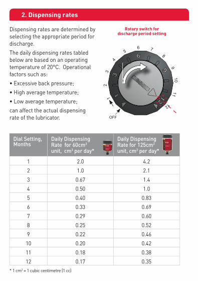
Dial Setting,Months
Daily Dispensing Rate for 60cm3 unit, cm3 per day*
Daily Dispensing Rate for 125cm3 unit, cm3 per day*
1 2.0 4.2
2 1.0 2.1
3 0.67 1.4
4 0.50 1.0
5 0.40 0.83
6 0.33 0.69
7 0.29 0.60
8 0.25 0.52
9 0.22 0.46
10 0.20 0.42
11 0.18 0.38
12 0.17 0.35* 1 cm3 = 1 cubic centimetre (1 cc)
2. Dispensing rates
Dispensing rates are determined by selecting the appropriate period for discharge.
The daily dispensing rates tabled below are based on an operating temperature of 20°C. Operational factors such as:
• Excessive back pressure;
• High average temperature;
• Low average temperature;
can affect the actual dispensing rate of the lubricator.
Rotary switch for discharge period setting
1
2
3
4
5 6 7 8 9 10 11 12
OFF
Gas generating unit. Refer to SDS for contents.

3. Remote installations
4. Mounting System Overview
10mm (3/8”) minimum internal diameter
Refer to sections 8, 9 and 10 for more information. perma FLEX lubricators are not included with kits.
K130S100 K1CHS100 K2CHG
Direct mount where possible and safe to do so as this provides maximum grease pressure to the bearing. For remote mounting use lines which are no more than 1 meter long with an internal diameter of 10mm (3/8”). Smaller diameter lines increase resistance to grease fl ow.
Always purge grease lines and pre-grease bearings. Minimise small diameter restrictions and confi rm that the bearing will receive grease freely.
10mm (3/8”) minimum internal diameter
Always purge grease lines and pre-grease bearings. Minimise small diameter restrictions and confi rm that the bearing will receive grease freely.
1 Meter max total line length
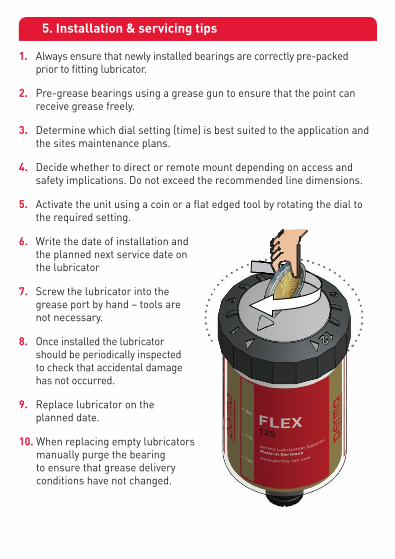
5. Installation & servicing tips
1. Always ensure that newly installed bearings are correctly pre-packed prior to fi tting lubricator.
2. Pre-grease bearings using a grease gun to ensure that the point can receive grease freely.
3. Determine which dial setting (time) is best suited to the application and the sites maintenance plans.
4. Decide whether to direct or remote mount depending on access and safety implications. Do not exceed the recommended line dimensions.
5. Activate the unit using a coin or a fl at edged tool by rotating the dial to the required setting.
6. Write the date of installation and the planned next service date on the lubricator
7. Screw the lubricator into the grease port by hand – tools are not necessary.
8. Once installed the lubricator should be periodically inspected to check that accidental damage has not occurred.
9. Replace lubricator on the planned date.
10. When replacing empty lubricators manually purge the bearing to ensure that grease delivery conditions have not changed.
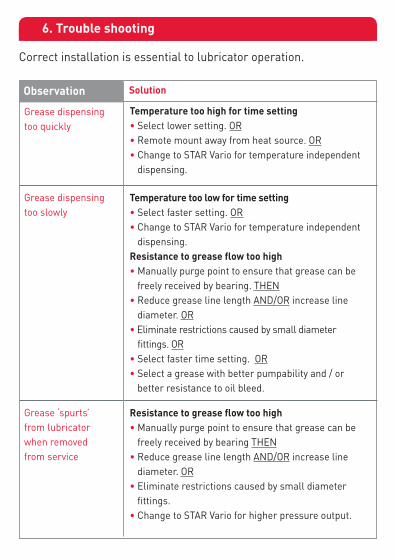
6. Trouble shooting
Correct installation is essential to lubricator operation.
Grease dispensing too quickly
Observation Solution
Temperature too high for time setting• Select lower setting. OR• Remote mount away from heat source. OR• Change to STAR Vario for temperature independent
dispensing.
Grease dispensing too slowly
Temperature too low for time setting • Select faster setting. OR• Change to STAR Vario for temperature independent
dispensing.Resistance to grease flow too high • Manually purge point to ensure that grease can be
freely received by bearing. THEN• Reduce grease line length AND/OR increase line
diameter. OR• Eliminate restrictions caused by small diameter fittings. OR• Select faster time setting. OR• Select a grease with better pumpability and / or
better resistance to oil bleed.
Grease ‘spurts’ from lubricator when removed from service
Resistance to grease flow too high • Manually purge point to ensure that grease can be
freely received by bearing THEN• Reduce grease line length AND/OR increase line
diameter. OR• Eliminate restrictions caused by small diameter
fittings.• Change to STAR Vario for higher pressure output.

7. Contamination prevention strategies
Different bearing configurations have different greasing requirements. The example here demonstrates the importance of preventing the ingress of solid contaminants and water.
For sites where contamination levels are high it is common to apply grease directly to taconite or labyrinth seals, in addition to the bearing. This provides a positive purge of grease to prevent the entry of contaminants.
Taconite seal purging and bearing relubrication on a plummer block bearing

8. Compact beam mount bracket & installation kits
For the quick installation of perma FLEX lubricators a compact bracket is combined with a 30mm* beam clamp. The bracket and clamp arrangement is also available in a range of pre-assembled kits.
A 1 x 1 point compact beam bracket E 1 x 90 degree elbow
B 1 x 30mm S/S beam clamp F 1 x ¼” BSPF–1/8”BSPM reducer
C 1 x Manual purge kit G 1 x ¼” BSPF -¼”BSPM extension
D 2 x Female swivel hose ends H 0.5m 3/8” ID grease line
C
B
A
H
D
Example of Kit Assembly – K130S50
Part Number Description
MB01SBC30 Bracket SS compact 1 point with 30mm beam clamp
K130S50 Kit SS 1 point BC30 0.5m hose with fittings
K130S75 Kit SS 1 point BC30 0.75m hose with fittings
K130S100 Kit SS 1 point BC30 1.0m hose with fittings
perma FLEX lubricators are not included with Kit Assemblies.
* 65mm beam clamps are available upon request.
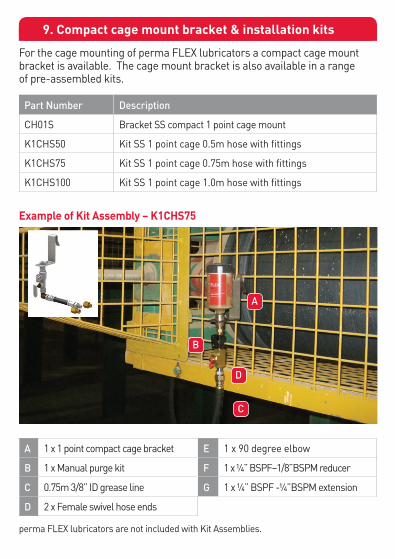
9. Compact cage mount bracket & installation kits
For the cage mounting of perma FLEX lubricators a compact cage mount bracket is available. The cage mount bracket is also available in a range of pre-assembled kits.
A 1 x 1 point compact cage bracket E 1 x 90 degree elbow
B 1 x Manual purge kit F 1 x ¼” BSPF–1/8”BSPM reducer
C 0.75m 3/8” ID grease line G 1 x ¼” BSPF -¼”BSPM extension
D 2 x Female swivel hose ends
Example of Kit Assembly – K1CHS75
Part Number Description
CH01S Bracket SS compact 1 point cage mount
K1CHS50 Kit SS 1 point cage 0.5m hose with fittings
K1CHS75 Kit SS 1 point cage 0.75m hose with fittings
K1CHS100 Kit SS 1 point cage 1.0m hose with fittings
perma FLEX lubricators are not included with Kit Assemblies.
C
D
B
A

10. Multi-point installation kits
The range of perma FLEX installation kits for multiple points are summarised in the table below.
A 1 x 2 point cage bracket E 2 x 90 degree elbows
B 2m 3/8” ID grease line F 2 x ¼” BSPF–1/8”BSPM reducers
C 2 x Manual purge kits G 2 x ¼” BSPF -¼”BSPM extensions
D 4 x Female swivel hose ends H
Example of Kit Assembly – K2CHG
Points Kit with BC30* Kit with BC65** Cage Hanger
2 points K230G K265G K2CHG
perma FLEX lubricators are not included with kits.
*BC30 = 30mm beam clamp **BC65 = 65mm beam clamp
C
B
A
D

Line Length Empty Line Part #’s Filled Lines Part #’s
0.5 meter 90HD0.5 PSFXXX90HD0.5*
0.75 meter 90HD0.75 PSFXXX90HD0.75*
1.0 meter 90HD1.0 PSFXXX90HD1.0*
The selection of correct grease lines and fittings is critical to good quality lubricator installations. Perma recommends grease lines with 3/8” internal diameter.
Pre-assembled grease lines are available to reduce installation time and ensure correct line selection. Lines are available empty or pre-filled with grease. For filled lines the grease type is denoted by a 6 digit code, shown here as PSFXXX.
The information provided in this Quick Reference guide is of a general nature only. Potential users of perma FLEX should seek advice tailored to their particular circumstances by contacting HTL perma Australia.
Further information about the perma FLEX is available from www.perma.com.au and www.perma-tec.com In particular the following documents are available for download:
• Safety Data Sheet
• Multi-language Operators Guide
11. Pre-assembled grease lines
12. Further Information
The information provided in this document is of a general nature only. Potential users of perma Automatic Lubricators should seek advice tailored to their particular circumstances and, for this purpose, are welcome to contact HTL Perma Australia Pty Ltd on the contact number provided. HTL Perma Australia Pty Ltd is not liable for any costs, losses or damages, whether direct or indirect, arising from any reliance upon this document. Details relating to product designs and specifications may be subject change without prior notice.
* “XXX” is replaced by a unique 3-digit code for each grease type.