Embed Size (px)
Citation preview
Performance Evaluation of the RF Receiver for Precision Positioning System
Hemish K. Parikh, Student Member ION, William R. Michalson, Member ION, R. James Duckworth
Electrical and Computer Engineering Department, Worcester Polytechnic Institute
BIOGRAPHY Hemish K. Parikh is a research assistant at Center for Advanced Integrated Radio Navigation (CAIRN) at Worcester Polytechnic Institute. He received his Bachelors degree in Electronic and Telecommunication Engineering form Bombay University, India in 2000 and M.S degree form University of Missouri - Columbia in 2002. He is currently pursuing his PhD in the ECE department at WPI. His research interest includes indoor precision position location systems and is currently involved in developing RF transmitter and receiver systems. Dr. William R. Michalson is an Associate Professor in the ECE Department at the Worcester Polytechnic Institute where he performs research and teaches in the areas of navigation, communications and computer system design. He supervises the WPI Center for Advanced Integrated Radio Navigation (CAIRN) and is the Director of the WPI Bioengineering Institute's Center for Untethered Healthcare. His research focuses on the development, test, and evaluation of systems, which combine communications and navigation. He has been involved with navigation projects for both civilian and military applications with a special emphasis on navigation and communication techniques in indoor, underground or otherwise GPS-deprived situations. Prior to joining the faculty at WPI, Dr. Michalson spent approximately 12 years at the Raytheon Company where he was involved with the development of embedded computers for guidance, communications and data processing systems for both space borne and terrestrial applications. Dr. R. James Duckworth is an Associate Professor in the Electrical and Computer Engineering department at WPI. He obtained his PhD in parallel processing from the University of Nottingham in England. He joined WPI in 1987. Duckworth teaches undergraduate and graduate course in computer engineering focusing on microprocessor and digital system design including using VHDL and Verilog for synthesis and modeling. His main research area is embedded system design. He has worked as a consultant for many companies on a wide variety of embedded system related projects. He is a member of theIEE, IEEE, and BCS and is a Chartered Engineer of the Engineering Council of the UK. ABSTRACT One of the major drivers for developing integrated navigation systems is the vision to provide first responders and healthcare providers, critical information where and when they need it. These integrated wireless devices of the future will assist the user with communications and incident management operations in the field in real time. The most important piece of such a system is clearly a ability to track and locate these wireless devices with high precision in a high-multipath environment. A previous paper presented a novel method for precise geolocation in indoor environments using an orthogonal frequency domain multiplexed (OFDM) signal consisting of many sinusoidal sub-carriers [1]. Unlike the ultra wideband signals that are often proposed for performing precision location in high multipath environments, the proposed signal structure is easily adapted to conform to existing spectral allocations. Further, the signal structure is capable of being used in coded orthogonal frequency domain multiplexing (COFDM) systems for supporting communications and navigation concurrently on the same radio channel. This technique is also well suited for use on ad hoc wireless networks, allowing the precision location of wireless nodes with respect to one another. This OFDM-based technique was first demonstrated using audio frequency signals rather than RF signals and is currently being implemented at RF. The focus of this paper is the design and performance evaluation of the RF front end receiver structure being developed for precision location system using this multi-carrier technique. The effect on the precision of the location estimate due to RF receiver design imperfections will be assessed and design issues for future receiver design improvements will be reviewed. INTRODUCTION An advanced personnel location and navigation system can be used in various applications; however the system
which is the subject of this paper is intended to track first responders in an emergency. Extensions to this system will allow sending instructions about future moves to the first responder and sending feedback about the physiological status of the first responder to a command center. Our solution is to develop a system that combines advanced navigation methods and robust communication techniques. A major challenge in developing such a system is satisfying the precise location estimate and high data rate requirements. The integrated system to be designed should be such that it is capable of location tracking and at the same time be capable of monitoring and transmitting physiological information like temperature, heart rate, blood oxygen level and other statistics, such as ambient temperature and breathing air level, related to the first responder. Methods which provide the accuracy needed to locate people in three dimensions inside complex buildings were reported previously [1, 2]. Figure 1 provides an overview of the location system. The system consists of many transceivers inside the building which communicate with other transceivers outside the building. The transceivers inside the building transmit a signal containing features for both navigation and data communications. This signal is received by various monitoring stations (currently radio receivers which pass their data to laptop computers). The signal processing algorithms implemented on the laptop computers provide the location of the wireless device. The movements of the mobile wireless device inside the building are also tracked by one or more monitoring stations which may be equipped with the building floor plan. Information about emergency exit paths, stairways, fire hydrants and other features of the environment is transmitted to the wireless device, allowing the user to operate more safely and efficiently.
Figure 1: Location System Overview One solution of particular interest is discussed in [2] which proposes a method for precise geolocation in a high multipath environment. This technique applies a matrix- decomposition-based multi-carrier range recovery algorithm to obtain a super resolution location solution. The design of the signal structure and the signal processing algorithms discussed by the authors is a very good choice for position location systems for two important reasons. First, the signal structure is easily
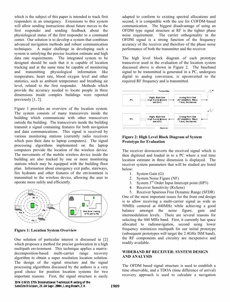
adapted to conform to existing spectral allocations and second, it is compatible with the use for COFDM-based communication. The biggest disadvantage of using an OFDM type signal structure at RF is the tighter phase noise requirement. The carrier orthogonality in the OFDM signal is a strong function of the frequency accuracy of the receiver and therefore of the phase noise performance of both the transmitter and the receiver. The high level block diagram of each prototype transceiver used in the evaluation of the location system discussed above is shown in Figure 2. The baseband signal to be transmitted is generated in a PC, undergoes digital to analog conversion, is upconverted to the required RF frequency and is transmitted.
Figure 2: High Level Block Diagram of System Prototype for Evaluation The receiver downconverts the received signal which is then digitized and loaded in to a PC where a real time location estimate in three dimension is displayed. The receiver system parameters that will be studied are listed below:
1. System Gain (G) 2. System Noise Figure (NF) 3. System 3rd Order Input Intercept point (IIP3) 4. Receiver Sensitivity (RxSens) 5. Receiver Spurious Free Dynamic Range (SFDR)
One of the most important issues for the front end design is to allow receiving a multi-carrier signal as wide as 50MHz centered at 440MHz while achieving a good balance amongst the noise figure, gain and intermodulation levels. There are several reasons for selecting the 440 MHz band. First, it currently has space allocated to radionavigation, second using lower frequency minimizes multipath for our initial prototype (subsequent prototypes will target the 2.4GHz ISM band), the RF components and circuitry are inexpensive and readily available. WIDEBAND RF RECEIVER: SYSTEM DESIGN AND ANALYSIS The OFDM based signal structure is used to establish a time observable, and a TDOA (time difference of arrival) recovery approach is used to calculate a navigation
solution. This new precision positioning method is based on the transmission of a continuous multi-carrier signal of the form.
∑−
=
+∆+=1
0
)(2)(M
m
tfmfjcc
moeAts φπ (1)
where M is the number of sinusoidal carriers with frequency spacing f∆ and each carrier has arbitrary
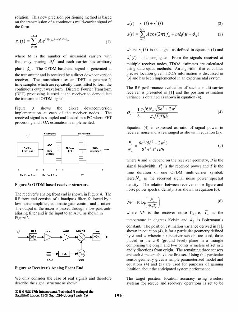
phase mφ . The OFDM baseband signal is generated at the transmitter and is received by a direct downconversion receiver. The transmitter uses an IDFT to generate N time samples which are repeatedly transmitted to form the continuous output waveform. Discrete Fourier Transform (DFT) processing is used at the receiver to demodulate the transmitted OFDM signal. Figure 3 shows the direct downconversion implementation at each of the receiver nodes. The received signal is sampled and loaded in a PC where FFT processing and TOA estimation is implemented.
Figure 3: OFDM based receiver structure The receiver’s analog front end is shown in Figure 4. The RF front end consists of a bandpass filter, followed by a low noise amplifier, automatic gain control and a mixer. The output of the mixer is passed through a low pass anti-aliasing filter and is the input to an ADC as shown in Figure 3.
Figure 4: Receiver's Analog Front End We only consider the case of real signals and therefore describe the signal structure as shown:
)()()( * tststs cc += (2)
∑−
=
+∆+=1
0))(2cos()(
M
mmo tfmfAts φπ (3)
where )(tsc is the signal as defined in equation (1) and
)(* tsc is its conjugate. From the signals received at multiple receiver nodes, TDOA estimates are calculated using state space methods. An algorithm that calculates precise location given TDOA information is discussed in [3] and has been implemented in an experimental system. The RF performance evaluation of such a multi-carrier receiver is presented in [1] and the position estimation variance is obtained as shown in equation (4).
TBhPwhNc
s
or π
σ22 256
81 +
= (4)
Equation (4) is expressed as ratio of signal power to receiver noise and is rearranged as shown in equation (5).
TBhwhc
NP
ro
s222
222
8)25(6
σπ+= (5)
where h and w depend on the receiver geometry, B is the signal bandwidth, sP is the received power and T is the time duration of one OFDM multi-carrier symbol. Here oN is the received signal noise power spectral density. The relation between receiver noise figure and noise power spectral density is as shown in equation (6).
=
ab
o
TkN
NF4
log10 (6)
where NF is the receiver noise figure, aT is the
temperature in degrees Kelvin and bk is Boltzmann’s constant. The position estimation variance derived in [1], shown in equation (4), is for a particular geometry defined by h and w wherein six receiver sensors are used, three placed in the z=0 (ground level) plane in a triangle comprising the origin and two points w meters offset in x and y directions from origin. The remaining three sensors are each h meters above the first set. Using this particular sensor geometry gives a simple parameterized model and equations (4) and (5) are used for purposes of gaining intuition about the anticipated system performance. The target position location accuracy using wireless systems for rescue and recovery operations is set to be
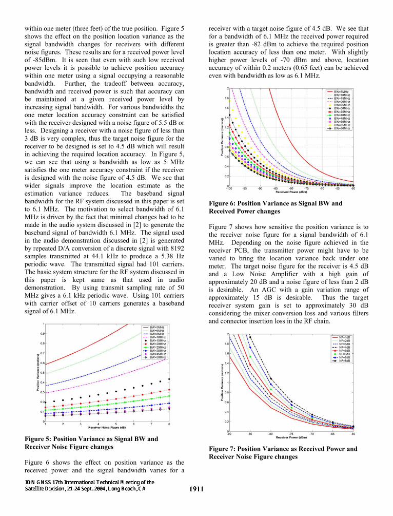
within one meter (three feet) of the true position. Figure 5 shows the effect on the position location variance as the signal bandwidth changes for receivers with different noise figures. These results are for a received power level of -85dBm. It is seen that even with such low received power levels it is possible to achieve position accuracy within one meter using a signal occupying a reasonable bandwidth. Further, the tradeoff between accuracy, bandwidth and received power is such that accuracy can be maintained at a given received power level by increasing signal bandwidth. For various bandwidths the one meter location accuracy constraint can be satisfied with the receiver designed with a noise figure of 5.5 dB or less. Designing a receiver with a noise figure of less than 3 dB is very complex, thus the target noise figure for the receiver to be designed is set to 4.5 dB which will result in achieving the required location accuracy. In Figure 5, we can see that using a bandwidth as low as 5 MHz satisfies the one meter accuracy constraint if the receiver is designed with the noise figure of 4.5 dB. We see that wider signals improve the location estimate as the estimation variance reduces. The baseband signal bandwidth for the RF system discussed in this paper is set to 6.1 MHz. The motivation to select bandwidth of 6.1 MHz is driven by the fact that minimal changes had to be made in the audio system discussed in [2] to generate the baseband signal of bandwidth 6.1 MHz. The signal used in the audio demonstration discussed in [2] is generated by repeated D/A conversion of a discrete signal with 8192 samples transmitted at 44.1 kHz to produce a 5.38 Hz periodic wave. The transmitted signal had 101 carriers. The basic system structure for the RF system discussed in this paper is kept same as that used in audio demonstration. By using transmit sampling rate of 50 MHz gives a 6.1 kHz periodic wave. Using 101 carriers with carrier offset of 10 carriers generates a baseband signal of 6.1 MHz.
Figure 5: Position Variance as Signal BW and Receiver Noise Figure changes Figure 6 shows the effect on position variance as the received power and the signal bandwidth varies for a
receiver with a target noise figure of 4.5 dB. We see that for a bandwidth of 6.1 MHz the received power required is greater than -82 dBm to achieve the required position location accuracy of less than one meter. With slightly higher power levels of -70 dBm and above, location accuracy of within 0.2 meters (0.65 feet) can be achieved even with bandwidth as low as 6.1 MHz.
Figure 6: Position Variance as Signal BW and Received Power changes Figure 7 shows how sensitive the position variance is to the receiver noise figure for a signal bandwidth of 6.1 MHz. Depending on the noise figure achieved in the receiver PCB, the transmitter power might have to be varied to bring the location variance back under one meter. The target noise figure for the receiver is 4.5 dB and a Low Noise Amplifier with a high gain of approximately 20 dB and a noise figure of less than 2 dB is desirable. An AGC with a gain variation range of approximately 15 dB is desirable. Thus the target receiver system gain is set to approximately 30 dB considering the mixer conversion loss and various filters and connector insertion loss in the RF chain.
Figure 7: Position Variance as Received Power and Receiver Noise Figure changes

Figure 8 shows the minimum required SNR for various accuracy targets using a receiver having a gain of 30dB and noise figure of 4.5 dB. We see that increasing the signal bandwidth improves the location variance but at the same time makes the system design more difficult and complex. The best case location variance of 0.1 meter (0.3 feet) requires that the minimum required SNR for signal a bandwidth of 6.1 MHz be about 10 dB.
Figure 8: Minimum SNR for required position location variance Thus, the receiver will be designed with the minimum required SNR set at 12 dB, slightly higher than the minimum required making sure the location error is within 0.1 meters (0.3 feet). The receiver sensitivity plays an important role in determining the communication range of the system. The degradation of receiver sensitivity reduces the maximum possible communication range. Given the receiver noise figure, the signal bandwidth and the worst case minimum required SNR the target receiver sensitivity is calculated using equation (7).
BWSNRNFdBmRxSens log10174 min +++−=
dBmRxSensMHzdBmRxSens
6.89)1.6log(10125.4174
−=+++−=
(7) The receiver third order input intercept point (IIP3) also plays an important role in suppressing the intermodulation products and higher the intercept point implies a receiver with better dynamic range. The spurious free dynamic range can be calculated using equation (8).
)3(32 RxSensIIPSFDR −= (8)
The desired target IIP3 specification for our system is set to be -10 dBm. Thus given the target receiver sensitivity and the target IIP3, the target SFDR is set at 53 dB. It is clear from Figure 9 that smaller signal bandwidths result in better receiver sensitivity and higher dynamic
range, however these improvements come at the cost of deteriorating location estimate accuracy. Thus, an important tradeoff must be made to operate the system using a particular signal bandwidth that also achieves the location accuracy goal. One possibility is to keep the signal bandwidth variable and adaptive depending upon the wireless channel and the environment. The use of a “software radio” design approach makes this possible without any changes in the receiver hardware. Figure 9 also shows the effect of signal bandwidth on receiver sensitivity and the spurious free dynamic range (assuming the minimum required SNR is 12dB).
Figure 9: Effect of varying the Signal BW on Sensitivity and SFDR The required minimum SNR to achieve various position location variances was shown in Figure 8. If the location accuracy is relaxed then the required minimum SNR can also be relaxed and hence the target receiver sensitivity will also change. Figure 10 can be used as a reference figure to determine the target receiver sensitivity for various levels of location accuracy requirements.
Figure 10: Min required SNR and min required antenna voltage for various values of receiver sensitivity that can be achieved.
The required input voltage at the antenna in dB micro Volts necessary to achieve a particular SNR for a fixed bandwidth of 6.1MHz is shown in Figure 10. WIDEBAND RF RECEIVER: SYSTEM SPECIFICATION The component selection is a critical part of optimizing the receiver performance and achieving a good balance amongst the noise figure, gain and intermodulation levels. The target system parameters for the receiver to be designed are listed below:
1. Location Variance: 0.1 meters (0.3 feet) 2. System Gain (G): 30 dB 3. System Noise Figure (NF): 4.5 dB 4. System 3rd Order Input Intercept point (IIP3): -
10dBm 5. Receiver Sensitivity (RxSens): -89.6 dBm 6. Receiver Spurious Free Dynamic Range
(SFDR): 53 dB This section discusses the detailed specifications and characteristics of the receiver building blocks used and will present an evaluation of the receiver system parameters achieved in practice. The portable receiver antenna used is a unity gain antenna with a wide bandwidth from 400 MHz to 512 MHz. The RF bandpass filter (BPF) used is a tubular filter with a sharp roll off at the 3 dB cutoff frequencies. The BPF is designed with a low insertion loss of 1.65 dB (max) at the passband center and has a 3 dB bandwidth of 50 MHz centered at 440 MHz. The 40 dB bandwidth is 120 MHz with 40 dB attenuation at 380 MHz on the lower side and 500 MHz on the upper side. Thus, the current receiver setup allows the system to operate on an OFDM signal as wide as 50 MHz. The low noise amplifier (LNA) follows the BPF. The selection of the LNA is very crucial as the noise figure of the LNA sets the noise figure of the receiver. The LNA chosen has a high gain of 22.5 dB and a low noise figure of 1.6 dB (max). The typical IIP3 value for the LNA is -5.5 dBm and the maximum input RF level is 10dBm. The wideband variable gain amplifier (VGA) that follows the LNA has a gain variation range of 15.5 dB, a high input intercept point of 15.5 dBm and is capable of receiving a maximum RF input power of 12 dBm. A high performance active mixer is used as a direct down-converter. The required local oscillator signal to drive the mixers should be between -12 dBm and -3 dBm. An RF PLL frequency synthesizer provides the mixer with the required local oscillator signal. The crystal oscillator used in the PLL synthesizer is a 10 MHz TCXO and has a frequency stability of 2.5 ppm. The VCO used in the PLL circuit has a frequency range of 415 MHz to 475 MHz, a tuning sensitivity of 10 MHz/V and an output phase noise of -136 dBc/Hz. The 2nd and 3rd harmonic suppressions at the VCO output are -18 dBm and -20 dBm respectively. A nine-section, Chebychev lowpass
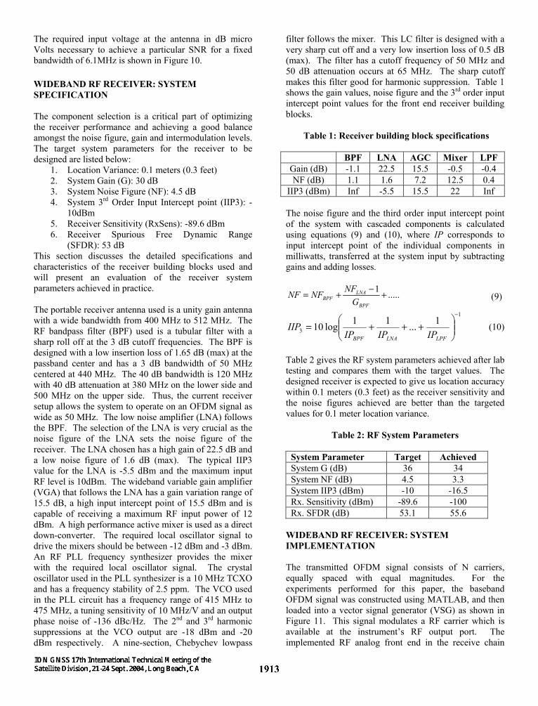
filter follows the mixer. This LC filter is designed with a very sharp cut off and a very low insertion loss of 0.5 dB (max). The filter has a cutoff frequency of 50 MHz and 50 dB attenuation occurs at 65 MHz. The sharp cutoff makes this filter good for harmonic suppression. Table 1 shows the gain values, noise figure and the 3rd order input intercept point values for the front end receiver building blocks.
Table 1: Receiver building block specifications
BPF LNA AGC Mixer LPF Gain (dB) -1.1 22.5 15.5 -0.5 -0.4 NF (dB) 1.1 1.6 7.2 12.5 0.4
IIP3 (dBm) Inf -5.5 15.5 22 Inf
The noise figure and the third order input intercept point of the system with cascaded components is calculated using equations (9) and (10), where IP corresponds to input intercept point of the individual components in milliwatts, transferred at the system input by subtracting gains and adding losses.
.....1 +−+=BPF
LNABPF G
NFNFNF (9)
1
31...11log10
−
+++=
LPFLNABPF IPIPIPIIP (10)
Table 2 gives the RF system parameters achieved after lab testing and compares them with the target values. The designed receiver is expected to give us location accuracy within 0.1 meters (0.3 feet) as the receiver sensitivity and the noise figures achieved are better than the targeted values for 0.1 meter location variance.
Table 2: RF System Parameters
System Parameter Target Achieved System G (dB) 36 34 System NF (dB) 4.5 3.3 System IIP3 (dBm) -10 -16.5 Rx. Sensitivity (dBm) -89.6 -100 Rx. SFDR (dB) 53.1 55.6
WIDEBAND RF RECEIVER: SYSTEM IMPLEMENTATION The transmitted OFDM signal consists of N carriers, equally spaced with equal magnitudes. For the experiments performed for this paper, the baseband OFDM signal was constructed using MATLAB, and then loaded into a vector signal generator (VSG) as shown in Figure 11. This signal modulates a RF carrier which is available at the instrument’s RF output port. The implemented RF analog front end in the receive chain
consists of antenna, RF amplifiers, a PLL synthesizer for generating local oscillator (LO) signal, mixer and filters. The filter at the front of the receive chain limits the bandwidth of the input spectrum to minimize inter-modulation and spurious responses. There are two possible configurations in the receiver’s front end. The first case is the low noise amplifier before the bandpass filter which gives a better receiver cumulative noise figure but leaves the LNA unprotected from the out-of-band interfering signals. In the second case, the bandpass filter is the first block and then the LNA follows. In this case the cumulative noise figure is higher than the first case but the LNA is protected from unwanted interfering signals. The test setup for the receiver uses this second configuration as it possible to achieve the target noise figure of 4.5 dB using this second configuration, thus protecting the receiver from interfering signals as well as achieve the required accuracy. The Variable Gain Amplifier (VGA) is used following the low noise amplifier, which is the input to the down converting mixer. The amplifier stages boost the signal energy and bring it to the appropriate level before mixing with the LO signal. A PLL frequency synthesizer is used to generate LO signal to the mixer. Some of the desirable characteristics of the LO source are low phase noise and sufficient power to drive the mixer.
Figure 11: RF Transceiver Setup A proof of concept demonstration using RF signals was successfully implemented using a software radio realization based on a MATLAB script executing on a general-purpose laptop computer.
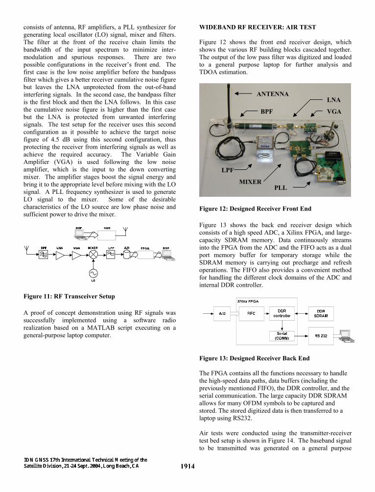
WIDEBAND RF RECEIVER: AIR TEST Figure 12 shows the front end receiver design, which shows the various RF building blocks cascaded together. The output of the low pass filter was digitized and loaded to a general purpose laptop for further analysis and TDOA estimation.
Figure 12: Designed Receiver Front End Figure 13 shows the back end receiver design which consists of a high speed ADC, a Xilinx FPGA, and large-capacity SDRAM memory. Data continuously streams into the FPGA from the ADC and the FIFO acts as a dual port memory buffer for temporary storage while the SDRAM memory is carrying out precharge and refresh operations. The FIFO also provides a convenient method for handling the different clock domains of the ADC and internal DDR controller.
Figure 13: Designed Receiver Back End The FPGA contains all the functions necessary to handle the high-speed data paths, data buffers (including the previously mentioned FIFO), the DDR controller, and the serial communication. The large capacity DDR SDRAM allows for many OFDM symbols to be captured and stored. The stored digitized data is then transferred to a laptop using RS232. Air tests were conducted using the transmitter-receiver test bed setup is shown in Figure 14. The baseband signal to be transmitted was generated on a general purpose
ANTENNA
LPF
BPF
MIXERPLL
VGA
LNA
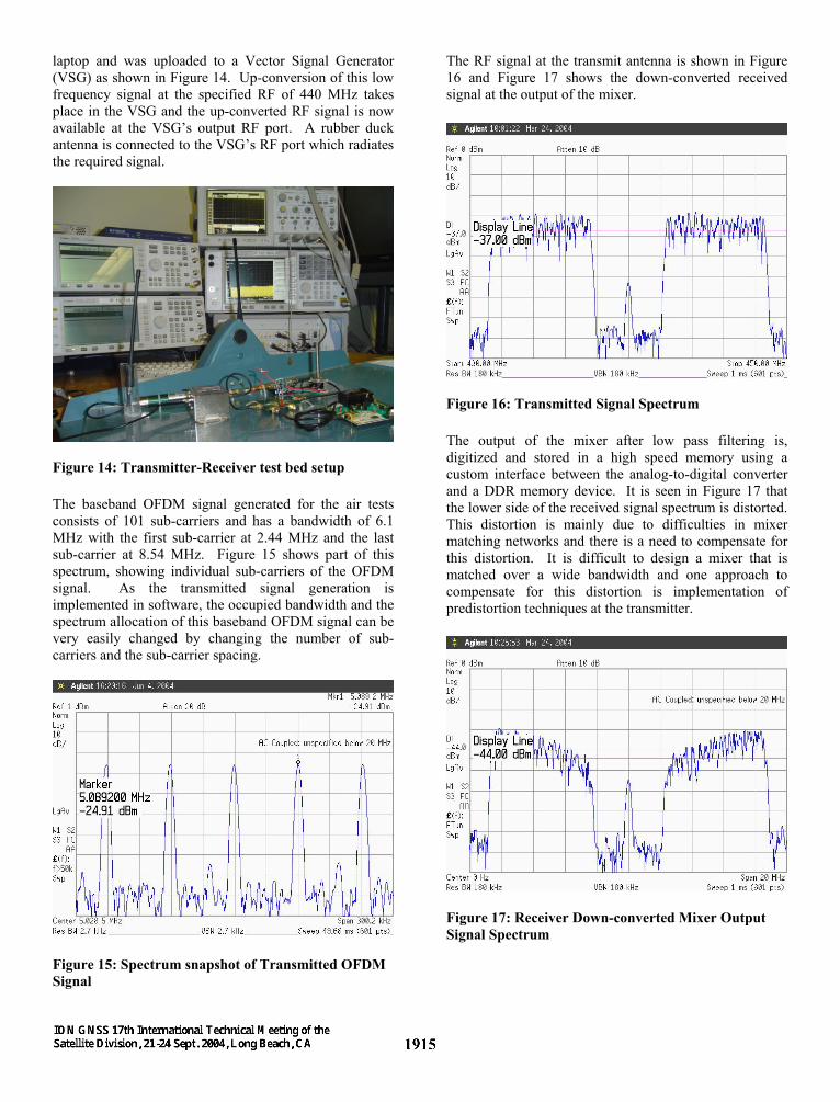
laptop and was uploaded to a Vector Signal Generator (VSG) as shown in Figure 14. Up-conversion of this low frequency signal at the specified RF of 440 MHz takes place in the VSG and the up-converted RF signal is now available at the VSG’s output RF port. A rubber duck antenna is connected to the VSG’s RF port which radiates the required signal.
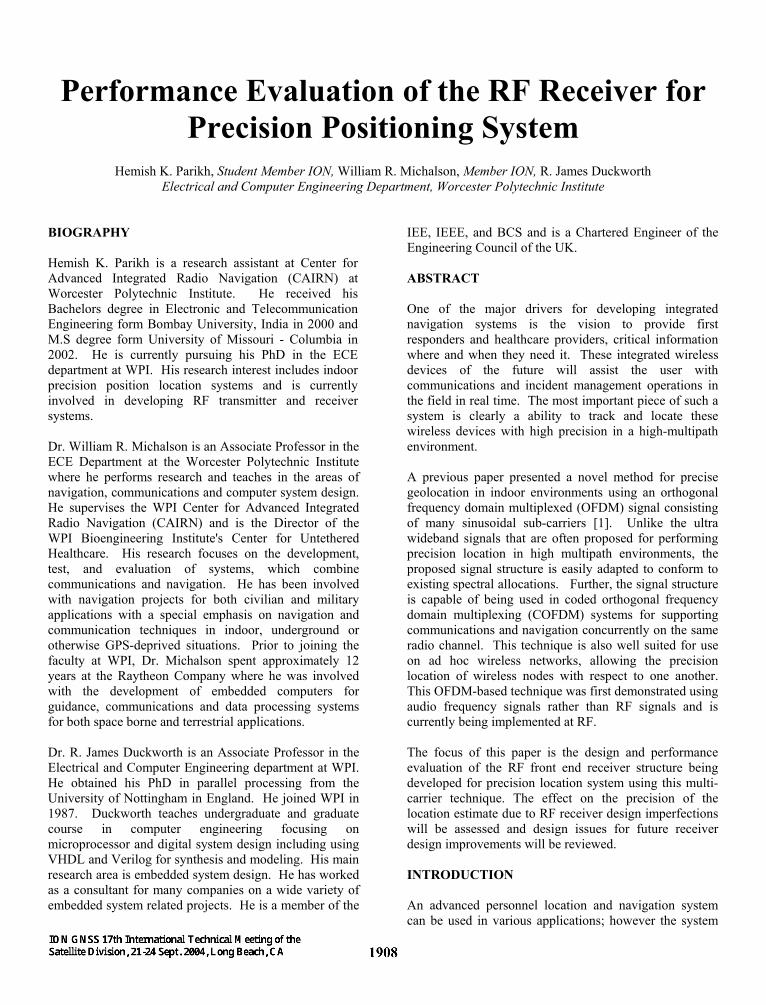
Figure 14: Transmitter-Receiver test bed setup The baseband OFDM signal generated for the air tests consists of 101 sub-carriers and has a bandwidth of 6.1 MHz with the first sub-carrier at 2.44 MHz and the last sub-carrier at 8.54 MHz. Figure 15 shows part of this spectrum, showing individual sub-carriers of the OFDM signal. As the transmitted signal generation is implemented in software, the occupied bandwidth and the spectrum allocation of this baseband OFDM signal can be very easily changed by changing the number of sub-carriers and the sub-carrier spacing.
Figure 15: Spectrum snapshot of Transmitted OFDM Signal
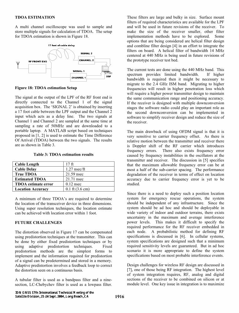
The RF signal at the transmit antenna is shown in Figure 16 and Figure 17 shows the down-converted received signal at the output of the mixer.
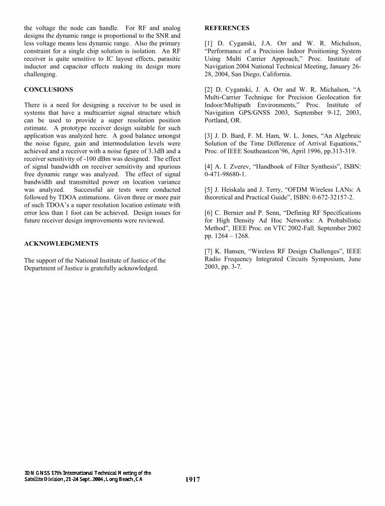
Figure 16: Transmitted Signal Spectrum The output of the mixer after low pass filtering is, digitized and stored in a high speed memory using a custom interface between the analog-to-digital converter and a DDR memory device. It is seen in Figure 17 that the lower side of the received signal spectrum is distorted. This distortion is mainly due to difficulties in mixer matching networks and there is a need to compensate for this distortion. It is difficult to design a mixer that is matched over a wide bandwidth and one approach to compensate for this distortion is implementation of predistortion techniques at the transmitter.
Figure 17: Receiver Down-converted Mixer Output Signal Spectrum
TDOA ESTIMATION A multi channel oscilloscope was used to sample and store multiple signals for calculation of TDOA. The setup for TDOA estimation is shown in Figure 18.
Figure 18: TDOA estimation Setup The signal at the output of the LPF of the RF front end is directly connected to the Channel 1 of the signal acquisition box. The ‘SIGNAL 2’ is obtained by inserting a 17 foot cable between the LPF output and the Channel 2 input which acts as a delay line. The two signals at Channel 1 and Channel 2 are sampled at the same time at sampling a rate of 50MHz and are downloaded to a portable laptop. A MATLAB script based on techniques proposed in [1, 2] is used to estimate the Time Difference Of Arrival (TDOA) between the two signals. The results are as shown in Table 3.
Table 3: TDOA estimation results Cable Length 17 ft Cable Delay 1.27 nsec/ft True TDOA 21.59 nsec Estimated TDOA 21.71 nsec TDOA estimate error 0.12 nsec Location Accuracy 0.1 ft (3.6 cm) A minimum of three TDOA’s are required to determine the location of the transceiver device in three dimensions. Using super resolution techniques, the location estimate can be achieved with location error within 1 foot. FUTURE CHALLENGES The distortion observed in Figure 17 can be compensated using predistortion techniques at the transmitter. This can be done by either fixed predistortion techniques or by using adaptive predistortion techniques. Fixed predistortion methods are the simplest forms to implement and the information required for predistortion of a signal can be predetermined and stored in a memory. Adaptive predistortion involves a feedback loop to correct the distortion seen on a continuous basis. A tubular filter is used as a bandpass filter and a nine-section, LC-Chebychev filter is used as a lowpass filter.
These filters are large and bulky in size. Surface mount filters of required characteristics are available for the LPF and will be used in future revisions of the receiver. To make the size of the receiver smaller, other filter implementation methods have to be explored. Some options that are being considered are helical filter design and combline filter design [4] in an effort to integrate the filters on board. A helical filter of bandwidth 14 MHz centered at 440 MHz is being used in future revisions of the prototype receiver test bed. The current tests are done using the 440 MHz band. This spectrum provides limited bandwidth. If higher bandwidth is required then it might be necessary to migrate to the 2.4 GHz ISM band. Migrating to higher frequencies will result in higher penetration loss which will require a higher power transmitter design to maintain the same communication range and positioning accuracy. If the receiver is designed with multiple downconversion stages the software radio could play an important role as the second downconversion can be implemented in software to simplify receiver design and reduce the size of the receiver. The main drawback of using OFDM signal is that it is very sensitive to carrier frequency offset. As there is relative motion between the transmitter and receiver there is Doppler shift of the RF carrier which introduces frequency errors. There also exists frequency error caused by frequency instabilities in the oscillators at the transmitter and receiver. The discussion in [5] specifies that the maximum allowable frequency error can be at most a half of the sub-carrier spacing. The performance degradation of the receiver in terms of effect on location accuracy due to carrier frequency error is yet to be studied. Since there is a need to deploy such a position location system for emergency rescue operations, the system should be independent of any infrastructure. Since the system should be ad hoc and should be deployable in wide variety of indoor and outdoor terrains, there exists uncertainty in the maximum and average interference power levels. This makes it difficult to specify the required performance for the RF receiver embedded in each node. A probabilistic method for defining RF specifications is discussed in [6]. In cellular systems, system specifications are designed such that a minimum required sensitivity levels are guaranteed. But in ad hoc scenario it is more appropriate to define the system specifications based on most probable interference events. Design challenges for wireless RF design are discussed in [7], one of those being RF integration. The highest level of system integration requires, RF, analog and digital sections of the receiver to be combined on silicon or at module level. One key issue in integration is to maximize
the voltage the node can handle. For RF and analog designs the dynamic range is proportional to the SNR and less voltage means less dynamic range. Also the primary constraint for a single chip solution is isolation. An RF receiver is quite sensitive to IC layout effects, parasitic inductor and capacitor effects making its design more challenging. CONCLUSIONS There is a need for designing a receiver to be used in systems that have a multicarrier signal structure which can be used to provide a super resolution position estimate. A prototype receiver design suitable for such application was analyzed here. A good balance amongst the noise figure, gain and intermodulation levels were achieved and a receiver with a noise figure of 3.3dB and a receiver sensitivity of -100 dBm was designed. The effect of signal bandwidth on receiver sensitivity and spurious free dynamic range was analyzed. The effect of signal bandwidth and transmitted power on location variance was analyzed. Successful air tests were conducted followed by TDOA estimations. Given three or more pair of such TDOA’s a super resolution location estimate with error less than 1 foot can be achieved. Design issues for future receiver design improvements were reviewed. ACKNOWLEDGMENTS The support of the National Institute of Justice of the Department of Justice is gratefully acknowledged.
REFERENCES [1] D. Cyganski, J.A. Orr and W. R. Michalson, “Performance of a Precision Indoor Positioning System Using Multi Carrier Approach,” Proc. Institute of Navigation 2004 National Technical Meeting, January 26-28, 2004, San Diego, California. [2] D. Cyganski, J. A. Orr and W. R. Michalson, “A Multi-Carrier Technique for Precision Geolocation for Indoor/Multipath Environments,” Proc. Institute of Navigation GPS/GNSS 2003, September 9-12, 2003, Portland, OR. [3] J. D. Bard, F. M. Ham, W. L. Jones, “An Algebraic Solution of the Time Difference of Arrival Equations,” Proc. of IEEE Southeastcon’96, April 1996, pp.313-319. [4] A. I. Zverev, “Handbook of Filter Synthesis”, ISBN: 0-471-98680-1. [5] J. Heiskala and J. Terry, “OFDM Wireless LANs: A theoretical and Practical Guide”, ISBN: 0-672-32157-2. [6] C. Bernier and P. Senn, “Defining RF Specifications for High Density Ad Hoc Networks: A Probabilistic Method”, IEEE Proc. on VTC 2002-Fall. September 2002 pp. 1264 – 1268. [7] K. Hansen, “Wireless RF Design Challenges”, IEEE Radio Frequency Integrated Circuits Symposium, June 2003, pp. 3-7.