Embed Size (px)
Citation preview

PEG™
Programming Guide
Version 1.1.4 December 2009

PEG™ Programming Guide
V1.1.4 December 15, 2009 Copyright ©CalAmp DataCom Inc 2009 - i - CalAmp Proprietary & Confidential
Table of Contents _______________________________________________________ i
Table of Contents
1 Introduction ________________________________________________________ 1
1.1 About CalAmp – Who we are… __________________________________________ 1
1.2 About CalAmp – What we do… __________________________________________ 1
1.3 About this Manual _____________________________________________________ 1
1.4 About the Reader ______________________________________________________ 1
2 PEG Introduction __________________________________________________ 2
2.1 What is PEG? ________________________________________________________ 2
2.2 What is an Event? _____________________________________________________ 2
2.3 What are Triggers? _____________________________________________________ 3
2.4 What are Trigger Modifiers? ______________________________________________ 3
2.5 What are Conditions? ___________________________________________________ 3
2.6 What are Condition Modifiers? ____________________________________________ 3
2.7 What are Actions? _____________________________________________________ 4
2.8 What are Action Modifiers? ______________________________________________ 4
2.9 What is a PEG Script? __________________________________________________ 4
2.10 How is PEG Processed? _________________________________________________ 4
3 PEG Overview _____________________________________________________ 5
3.1 Reporting Data via PEG ________________________________________________ 5 3.1.1 Reporting via UDP/IP ________________________________________________________ 5 3.1.2 LM Direct Reporting _________________________________________________________ 6
3.1.2.1 Message Logging _____________________________________________________ 7 3.1.2.2 Creating Event Reports ________________________________________________ 7 3.1.2.3 Creating Mini Event Reports ____________________________________________ 8 3.1.2.4 Creating ID Reports and Version Reports __________________________________ 9 3.1.2.5 Working with the Log ________________________________________________ 10 3.1.2.6 Working with User Messages __________________________________________ 11 3.1.2.7 Changing the Inbound Address _________________________________________ 12
3.1.3 TAIP Reporting ____________________________________________________________ 13 3.1.4 SMS Reporting ____________________________________________________________ 13
3.2 Accumulators ________________________________________________________ 14 3.2.1 Accumulator Types __________________________________________________________ 14 3.2.2 Using Accumulators _________________________________________________________ 16
3.2.2.1 Accumulator Math ___________________________________________________ 20 3.2.3 Reporting Accumulators _______________________________________________________ 21
3.3 Timers _____________________________________________________________ 22 3.3.1 Using Timers ______________________________________________________________ 22
3.4 Time Distance Profiles _________________________________________________ 24 3.4.1 Using Time-Distance Profiles ___________________________________________________ 24

PEG™ Programming Guide
V1.1.4 December 15, 2009 Copyright ©CalAmp DataCom Inc 2009 - ii - CalAmp Proprietary & Confidential
3.5 Speed Thresholds and Movement ________________________________________ 26 3.5.1 Using Speed Thresholds _______________________________________________________ 26 3.5.2 Speed Debounce and Delays ____________________________________________________ 27 3.5.3 Detecting Movement _________________________________________________________ 27
3.6 Acceleration Profiles __________________________________________________ 29
3.7 Inputs _____________________________________________________________ 29 3.7.1 Using Discreet Inputs ________________________________________________________ 30 3.7.2 Using Input Debounce and Delay ________________________________________________ 31 3.7.3 Using Analog to Digital Inputs __________________________________________________ 32 3.7.4 Using the 1 Bit Bus (1-Wire® Interface) ___________________________________________ 34
3.8 Outputs ____________________________________________________________ 35
3.9 Zones and Geo-Zones _________________________________________________ 36 3.9.1 Zones ___________________________________________________________________ 36
3.9.1.1 Using Zones ________________________________________________________ 38 3.9.2 Geo Zones ________________________________________________________________ 39
3.9.2.1 Defining Geo-Zones __________________________________________________ 40 3.9.2.2 Programming Geo-Zones ______________________________________________ 41 3.9.2.3 Using Geo-Zones ____________________________________________________ 42
3.10 Text Messages _______________________________________________________ 44 3.10.1 Generic Messages ___________________________________________________________ 44 3.10.2 Status Messages ____________________________________________________________ 45 3.10.3 Position Messages ___________________________________________________________ 47
3.11 Binary Messages ______________________________________________________ 48 3.11.1 Using Custom Binary Messages __________________________________________________ 48 3.11.2 Using Canned Messages _______________________________________________________ 49
3.11.2.1 Mackenzie Labs DADS-A1214 _________________________________________ 49 3.11.2.2 Garmin NUVI ______________________________________________________ 50
3.12 PEG Flags __________________________________________________________ 51 3.12.1 Using PEG Flags __________________________________________________________ 51
3.13 PEG Enables and User Flags ____________________________________________ 52 3.13.1 Using User Flags ___________________________________________________________ 52 3.13.2 Using PEG Enables _________________________________________________________ 52
3.14 PEG State Variable ___________________________________________________ 53
3.15 Date and Time _______________________________________________________ 54 3.15.1 Using Date and Time ________________________________________________________ 54
3.16 GPS _______________________________________________________________ 56 3.16.1 Using GPS _______________________________________________________________ 56
3.16.1.1 GPS Position Accuracy Accumulator ____________________________________ 57 3.16.1.2 Requesting Time When GPS is not Available ______________________________ 57
3.17 Comm _____________________________________________________________ 58 3.17.1 Comm Terminology __________________________________________________________ 58 3.17.2 Using Comm ______________________________________________________________ 59 3.17.3 Using Voice Calls __________________________________________________________ 61
3.18 Power Management ___________________________________________________ 62 3.18.1 Using Power Management _____________________________________________________ 62
3.19 SMS _______________________________________________________________ 64
3.20 PEG Environments ___________________________________________________ 65

PEG™ Programming Guide
V1.1.4 December 15, 2009 Copyright ©CalAmp DataCom Inc 2009 - iii - CalAmp Proprietary & Confidential
3.20.1 Using Environments _________________________________________________________ 65
3.21 PEG Multiple Condition Management _____________________________________ 67 3.21.1 NOT Conditions ___________________________________________________________ 67 3.21.2 Combining Conditions ________________________________________________________ 67
3.22 PEG Functions ______________________________________________________ 68 3.22.1 END __________________________________________________________________ 68 3.22.2 JUMP __________________________________________________________________ 68 3.22.3 CALL and RETURN ______________________________________________________ 68 3.22.4 Any Trigger _______________________________________________________________ 68
3.23 Over-The Air Changes _________________________________________________ 69
4 PEG Programming _________________________________________________ 70
4.1 What is a PEG Script? – A reminder ______________________________________ 70
4.2 Planning a PEG Script _________________________________________________ 70 4.2.1 Collecting Customer Requirements ________________________________________________ 70 4.2.2 Evaluate the requirements ______________________________________________________ 71 4.2.3 Create/Architect a Solution approach ______________________________________________ 71 4.2.4 Develop the Solution/ Create a PEG Script _________________________________________ 72 4.2.5 Test the Solution ____________________________________________________________ 72 4.2.6 Deploy the Solution __________________________________________________________ 72 4.2.7 System Maintenance _________________________________________________________ 72
4.3 Creating PEG Scripts __________________________________________________ 72 4.3.1 Deciding on Trigger Modifiesr ___________________________________________________ 72 4.3.2 Deciding on Events __________________________________________________________ 73 4.3.3 Creating the Configuration _____________________________________________________ 73 4.3.4 Deploying a PEG Script ______________________________________________________ 73
5 PEG Programming Examples ________________________________________ 74
5.1 PEG Programming – Delivery Fleet _______________________________________ 75 5.1.1 Project Overview ____________________________________________________________ 75 5.1.2 Project Proposal ____________________________________________________________ 75
5.1.2.1 CalAmp LMU Requirements ___________________________________________ 75 5.1.2.2 Local Application Requirements ________________________________________ 77 5.1.2.3 Remote Application Requirements ______________________________________ 77
5.1.3 PEG Script - Planning _______________________________________________________ 78 5.1.4 PEG Script - Development _____________________________________________________ 80
5.1.4.1 PEG Script - Ignition On/Off Detection ___________________________________ 80 5.1.4.2 PEG Script – Sleep ___________________________________________________ 81 5.1.4.3 PEG Script – Time-Distance Reporting ___________________________________ 82 5.1.4.4 PEG Script – At Stop Timer ____________________________________________ 82 5.1.4.5 PEG Script – Moving/Not Moving Reporting ______________________________ 83 5.1.4.6 PEG Script - Speeding ________________________________________________ 84 5.1.4.7 PEG Script – Trip Odometer ___________________________________________ 86 5.1.4.8 PEG Script – Vehicle Idle and In Motion Time _____________________________ 86 5.1.4.9 PEG Script – Vehicle Power ___________________________________________ 90
5.1.5 Project Backend Requirements ___________________________________________________ 90
5.2 PEG Programming – Long Haul Trucks ___________________________________ 91 5.2.1 Project Overview ____________________________________________________________ 91 5.2.2 Project Proposal ____________________________________________________________ 91
5.2.2.1 Project Proposal – Trailer Tracking – LMU 1000 Requirements________________ 91 5.2.2.2 Project Proposal – Truck Tracking – LMU 4100 Requirements ________________ 92 5.2.2.3 Project Proposal – Local Application _____________________________________ 92
PEG™ Programming Guide
V1.1.4 December 15, 2009 Copyright ©CalAmp DataCom Inc 2009 - iv - CalAmp Proprietary & Confidential
5.2.2.4 Project Proposal – Remote Application ___________________________________ 93 5.2.3 PEG Script – Planning _______________________________________________________ 93 5.2.4 PEG Script Development – LMU-1000 ___________________________________________ 96
5.2.4.1 PEG Script – Trigger Modifiers _________________________________________ 96 5.2.4.2 PEG Script – In Use / Not In Use ________________________________________ 96 5.2.4.3 PEG Script – In Use - Trailer Connect ____________________________________ 97 5.2.4.4 PEG Script – In Use - Load Begin/End ___________________________________ 98 5.2.4.5 PEG Script - In Use - Unload Begin/End Detection _________________________ 98 5.2.4.6 PEG Script – In Use - Distance Travelled _________________________________ 99 5.2.4.7 PEG Script –In Use – Power-down for Load/Unload ________________________ 99 5.2.4.8 PEG Script – Not In Use - Trailer Disconnect _____________________________ 100 5.2.4.9 PEG Script – Not In Use – Low Battery _________________________________ 100 5.2.4.10 PEG Script – Not In Use – Daily Report _________________________________ 100 5.2.4.11 PEG Script – Not In Use – Distance Travelled ____________________________ 100 5.2.4.12 PEG Script – Not In Use – Sleep _______________________________________ 101
5.2.5 PEG Script – Development – LMU 4100 _________________________________________ 101 5.2.5.1 PEG Script – Trigger Modifiers ________________________________________ 101 5.2.5.2 PEG Script - Ignition On/Off Detection __________________________________ 102 5.2.5.3 PEG Script – Sleep __________________________________________________ 102 5.2.5.4 PEG Script – Time-Distance Reporting __________________________________ 103 5.2.5.5 PEG Script – Moving/Not Moving Reporting _____________________________ 104 5.2.5.6 PEG Script – Trip Odometer __________________________________________ 105 5.2.5.7 PEG Script – Vehicle Power __________________________________________ 105 5.2.5.8 PEG Script - Load Begin/End Detection _________________________________ 106 5.2.5.9 PEG Script - Unload Begin/End Detection _______________________________ 106 5.2.5.10 PEG Script – Trailer Detection ________________________________________ 107 5.2.5.11 PEG Script – Modem off during load and unload procedures _________________ 108 5.2.5.12 PEG Script –Unsafe load and unload warning _____________________________ 111 5.2.5.13 PEG Script –Crossing State Boundaries _________________________________ 112
5.3 PEG Programming – Taxi System _______________________________________ 114 5.3.1 Project Overview ___________________________________________________________ 114 5.3.2 Project Proposal ___________________________________________________________ 114
5.3.2.1 LMU Requirements _________________________________________________ 114 5.3.2.2 Local Application Requirements _______________________________________ 115 5.3.2.3 Remote Application Requirements _____________________________________ 115
5.3.3 PEG Script – Planning ______________________________________________________ 115 5.3.4 PEG Script - Development ____________________________________________________ 116
5.3.4.1 PEG Script – Time-Distance Reporting __________________________________ 116
Appendix A – PEG Triggers _____________________________________________ 118
Appendix B – PEG Conditions __________________________________________ 126
Appendix C – PEG Actions _____________________________________________ 136

PEG™ Programming Guide
V1.1.4 December 15, 2009 Copyright ©CalAmp DataCom Inc 2009 - 1 - CalAmp Proprietary & Confidential
1 1.1
Introduction
Founded in 1981, CalAmp stands at the forefront of technology evolution as a result of strategic collaborations with forward thinking customers. By anticipating technology and industry trends, we rapidly develop cutting-edge solutions to help our customers effectively realize time and cost savings. Based on our long history of successful product deployment we help our customers by managing the entire product lifecycle - from design to manufacturing to implementation.
About CalAmp – Who we are…
1.2 We are a recognized and trusted leader in satellite DBS technology, wireless networks, software application development, embedded computing and enterprise mobility. We are considered the solution industry’s foremost specialist in networking applications, wireless technoLogies, digital multimedia delivery, residential broadband data delivery, healthcare and medical and public safety.
About CalAmp – What we do…
1.3 This guide is meant to describe the Programmable Event Generator of the CalAmp LMU product lines. It is broken into three parts, an introduction which gives a brief description of PEG and its parts, an Overview section which describes each of the features within PEG and lastly, a series of PEG examples. This last section describes a fictitious set of customer requirements then shows users how to turn them into a functioning PEG Script.
About this Manual
1.4 This document is intended for any personnel who are required to design and develop a PEG Script. You are expected to have at least passing knowledge of some programming principles (loops, functions, Boolean operations, etc…) but need not be an expert in any language.
About the Reader
PEG™ Programming Guide
V1.1.4 December 15, 2009 Copyright ©CalAmp DataCom Inc 2009 - 2 - CalAmp Proprietary & Confidential
2 2.1
PEG Introduction
The Programmable Event Generator (PEG) is the means by which a user can customize the LMU to perform a specific task, or a series of tasks. This can be something as simple as creating a report every time the vehicle moves 1 kilometer or as complicated as managing messages and behaviors of peripheral devices such as card readers, cameras or messaging terminals. It may be easiest to think of PEG as a type of programming language, though it is really not that complicated.
What is PEG?
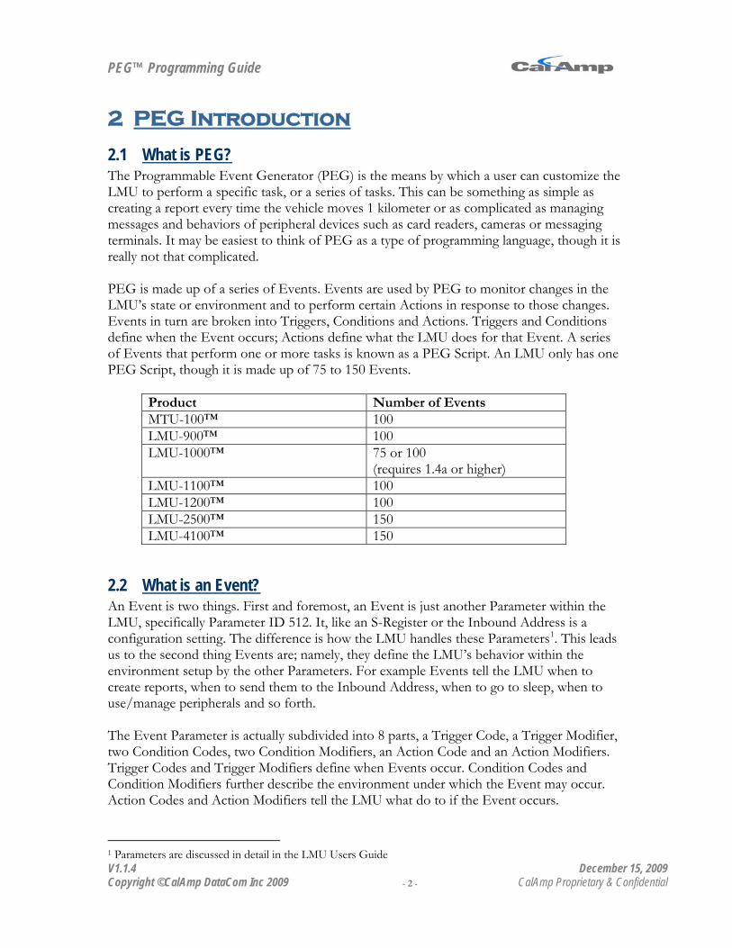
PEG is made up of a series of Events. Events are used by PEG to monitor changes in the LMU’s state or environment and to perform certain Actions in response to those changes. Events in turn are broken into Triggers, Conditions and Actions. Triggers and Conditions define when the Event occurs; Actions define what the LMU does for that Event. A series of Events that perform one or more tasks is known as a PEG Script. An LMU only has one PEG Script, though it is made up of 75 to 150 Events.
Product Number of Events MTU-100™ 100 LMU-900™ 100 LMU-1000™ 75 or 100
(requires 1.4a or higher) LMU-1100™ 100 LMU-1200™ 100 LMU-2500™ 150 LMU-4100™ 150
2.2 An Event is two things. First and foremost, an Event is just another Parameter within the LMU, specifically Parameter ID 512. It, like an S-Register or the Inbound Address is a configuration setting. The difference is how the LMU handles these Parameters
What is an Event?
1
. This leads us to the second thing Events are; namely, they define the LMU’s behavior within the environment setup by the other Parameters. For example Events tell the LMU when to create reports, when to send them to the Inbound Address, when to go to sleep, when to use/manage peripherals and so forth.
The Event Parameter is actually subdivided into 8 parts, a Trigger Code, a Trigger Modifier, two Condition Codes, two Condition Modifiers, an Action Code and an Action Modifiers. Trigger Codes and Trigger Modifiers define when Events occur. Condition Codes and Condition Modifiers further describe the environment under which the Event may occur. Action Codes and Action Modifiers tell the LMU what do to if the Event occurs.
1 Parameters are discussed in detail in the LMU Users Guide

PEG™ Programming Guide
V1.1.4 December 15, 2009 Copyright ©CalAmp DataCom Inc 2009 - 3 - CalAmp Proprietary & Confidential
2.3 Triggers define when an Event occurs. When a Trigger is set up, the LMU monitors for changes related to that Trigger (for instance, if a Timer value expires). When a Trigger occurs, the LMU will scan the Event list from Event 0 to Event 149 (or 74 or 99). It will attempt to process any Events associated with that Trigger in the order in which they occur in the Script.
What are Triggers?
The Trigger Code is a numeric value that represents the Trigger within the LMU. The Trigger Modifier piece of the Event is used to further describe a Trigger. For example, it can define which Timer the LMU should be monitoring. A complete listing of Triggers, their Trigger Codes and their associated Trigger Modifiers can be found in Appendix A.
2.4 Trigger Modifiers provide further definition to a Trigger when the Trigger alone could be ambiguous. For instance when using a Timer Timeout Trigger, the Trigger Modifier is used to define which Timer produced the Timeout.
What are Trigger Modifiers?
2.5 Conditions define the environment in which Events can occur. That is, for an active Trigger, the Conditions must be true in order for the Event’s Action to be performed. One common use for Conditions is monitoring the Ignition state for sleep. That is, the LMU should only go to sleep if the vehicle’s Ignition is off.
What are Conditions?
The Condition Code is a numeric value that represents the Condition within the LMU. Condition Modifiers are much like Trigger Modifiers in that they further define the Condition. For instance, it would allow a script to create one report if a Timer was active, but create a different report if that Timer was inactive. A complete listing of Conditions, their Condition Codes and their associated Condition Modifiers can be found in Appendix B.
2.6 Condition Modifiers, like Trigger Modifiers provide further definition of Conditions. These definitions can be selected from multiple options (e.g. which input to monitor), or define a particular state (e.g. the connection state of the wireless modem).
What are Condition Modifiers?

PEG™ Programming Guide
V1.1.4 December 15, 2009 Copyright ©CalAmp DataCom Inc 2009 - 4 - CalAmp Proprietary & Confidential
2.7 Actions define what the LMU will do when the Event occurs such as starting a Timer, switching an output, creating a report, forcing the LMU to go to sleep or resetting the wireless modem.
What are Actions?
Within the LMU, Actions are referenced by their Action Code. A complete listing of available Actions, their Action Codes and associated Action Modifiers can be found in Appendix C.
2.8 Action Modifiers are the descriptors of Actions. Like the Trigger Modifiers and Condition Modifiers they define the Action when it alone would be ambiguous. Common uses of Action Modifiers would be to define which Timer to start, what output to control or what Event Code should be used with a given report.
What are Action Modifiers?
2.9 A PEG script is a complete list of PEG Events that work together to perform one or more tasks.
What is a PEG Script?
2.10 PEG Parameters are any LMU configuration Parameters that are used directly by PEG. This includes Parameters such as Timer Timeouts, Accumulator Thresholds and Time-Distance Profiles. A complete list of the available PEG Parameters can be found in Appendix A of the LMU Users Guide.
What are PEG Parameters?
2.11 When a Trigger occurs, PEG posts it to a queue. PEG then pulls the first Trigger from the queue and makes a pass through the Event list starting with Event 0. When a matching Trigger is found, the corresponding Condition fields are tested. If the Conditions produce a ‘True’ answer, then the Action specified is executed. After the Action’s execution is requested, PEG continues its pass through the Event list looking for more matching Triggers. When the end of the list is reached, the next Trigger is immediately pulled from the queue and processed. This sequence is repeated until the queue is empty.
How is PEG Processed?
PEG™ Programming Guide
V1.1.4 December 15, 2009 Copyright ©CalAmp DataCom Inc 2009 - 5 - CalAmp Proprietary & Confidential
3 In the sections that follow we attempt to break down PEG into its functional components. For each we give a brief description of that component (i.e. why it exists and what it does) and then describe the accompanying PEG support.
PEG Overview
3.1 The most common, and usually the most important use of PEG is the ability to report location data to a backend system. Of course as PEG is something of a programming language it offers you a variety of options to perform this task.
Reporting Data via PEG
The LMU can make use of two transports to deliver its location data, either UDP/IP or SMS although, in the case of iDEN devices, only the UDP/IP transport is available.
3.1.1 Reporting via UDP/IP UDP/IP is the primary transport by which the LMU communicates with remote systems. Using this transport, the LMU supports two communications protocols, LM Direct and TAIP. LM Direct is by far the most feature rich of the two interfaces and should be implemented by anyone wanting to use the LMU. TAIP is a much simpler interface whose main role is to support some cross compatibility with existing reporting applications. The LM Direct protocol is described in detail in the LM Direct Reference Guide. The TAIP interface is described in the LMU Users Guide. The section that follows solely focuses on how each interface relates to PEG.
PEG™ Programming Guide
V1.1.4 December 15, 2009 Copyright ©CalAmp DataCom Inc 2009 - 6 - CalAmp Proprietary & Confidential
3.1.2 LM Direct Reporting LM Direct is the primary means for your backend system to communicate with an LMU. PEG makes use of 6 of the LM Direct message types. The message types are:
• Event Reports: Event Reports are the primary message used by the LMU to deliver location data.
• Mini Event Reports: The Mini Event reports are an alternate to the Event Reports. The Mini Event Report is a smaller size message containing approximately 20 bytes less information than the standard event report.
• User Messages: User Messages are messages sent to or from dumb serial devices connected to the LMU. PEG cannot generate User Messages on its own, but it can react to them.
• ID Reports: ID Reports contain a list of serial numbers for each of the LMU’s components as well as some version information. Generally the ID Report is only used in conjunction with the ‘Maintenance’ settings of the LMU. That is, the settings that enables the LMU to report to PULS.
• Version Reports: The Version Report is used to communicate the version strings of the LMU (i.e. APP, CPU, RADIO and GPS Versions). These strings are identical to the “ATI0” or “AT$APP VER?” responses.
• Acknowledgements: Acknowledgements (or ACKs for short) indicate that a particular message was successfully received and that the receiving side is ready for the next message. As a result, they are a cornerstone in the LMU’s Logging capabilities.
It is highly advisable that your LM Direct server be able to handle all LM Direct message types (e.g. ACK them) even if the data is not used by your application .As a bare minimum, users should implement an LM Direct server that supports Event Reports and Acknowledgements. Before we can talk about the various message types, it is essential that you understand how the LMU’s Log operates.

PEG™ Programming Guide
V1.1.4 December 15, 2009 Copyright ©CalAmp DataCom Inc 2009 - 7 - CalAmp Proprietary & Confidential
3.1.2.1 Message Logging There are three reporting modes that can be used with the LMU. They are commonly referred to as the following:
• Store and Forward (SNF): When a message is created using Store and Forward the LMU will attempt to immediately send the data if the network is available and if no other data is in the Log. Once the message is sent, the LMU will wait for an acknowledgement message from the receiving server. If one is not received, the LMU will Log the data. Any Logged data will be sent at a later point in time. If the LMU is either not online, or the Log is already active, the new data is placed at the end of the Log. In PEG, the phrases SEND or SEND-LOG indicate a message is created using the Store and Forward mechanism.
• Batch: In batch mode the LMU will immediately place the data in the Log regardless of network and Log states. The LMU will hold this data until it is explicitly told to empty its Log using a SEND LOG Action or a message using the Store and Forward mechanism is introduced. In PEG, an Action using just LOG operates in batch mode.
• Unacknowledged: Unacknowledged messages are ones that are never Logged. The LMU attempts to send the data if the network is available. Once the send has been completed, the message is erased. If the network is not available, then the message is immediately deleted. Within PEG, the phrases Unacknowledged or Un’Ack’d are used to refer to this reporting mode.
3.1.2.2 Creating Event Reports PEG offers five Actions that can create an Event Report.
• Send Report: • Send/Log Report: Send and Send/Log perform the same function; they create an
Event Report using the LMU’s Store and Forward Log mode. If the Log is inactive, the LMU will attempt to deliver the message to the Inbound address and port. If the Log is active, the LMU will place the Event report at the end of the Log.
• Log Report: This Action creates an Event Report using the LMU’s Batch Log mode, that is, the Event report is immediately put into the Log. It will only be delivered when the Log is forced to empty.
• Send Unacknowledged Report: This Action creates an Event Report using the unacknowledged service. Messages created in this mode are sent immediately and are not logged.
• Report Alert: This Action creates 3 Events reports, one using the Store and Forward service, one using the Unacknowledged service and one using SMS. Like the other four Actions, the Action Modifier defines the Event Code.
For each of these Actions, the Action Modifier defines the ‘Event Code’ field of the Event Report. The Event Code is best thought of as the reason why the Event Report was created.

PEG™ Programming Guide
V1.1.4 December 15, 2009 Copyright ©CalAmp DataCom Inc 2009 - 8 - CalAmp Proprietary & Confidential
For instance, an Event Code of 1 could indicate the vehicle ignition was turned on and an Event Code of 10 could mean the ignition has turned off. The actual assignment of Event Codes is completely up to the PEG Script developer, though it is best to keep Event Codes common across your Scripts. Event Codes can range from 0 to 255.
3.1.2.3 Creating Mini Event Reports PEG offers three Actions that can create a Mini Event Report.
• Send Mini Event Report: Send creates a Mini Event Report using the LMU’s Store and Forward Log mode. If the Log is inactive, the LMU will attempt to deliver the message to the Inbound address and port. If the Log is active, the LMU will place the Mini Event Report at the end of the Log.
• Log Mini Event Report: This Action creates a Mini Event Report using the LMU’s Batch Log mode, that is, the Mini Event Report is immediately put into the Log. It will only be delivered when the Log is forced to empty.
• Send Unacknowledged Mini Event Report: This Action creates a Mini Event Report using the unacknowledged service. Messages created in this mode are sent immediately and are not logged.
For each of these Actions, the Action Modifier defines the ‘Event Code’ field of the Mini Event Report. The Event Code is best thought of as the reason why the Mini Event Report was created. For instance, an Event Code of 1 could indicate the vehicle ignition was turned on and an Event Code of 10 could mean the ignition has turned off. The actual assignment of Event Codes is completely up to the PEG Script developer, though it is best to keep Event Codes common across your Scripts. Event Codes can range from 0 to 255.

PEG™ Programming Guide
V1.1.4 December 15, 2009 Copyright ©CalAmp DataCom Inc 2009 - 9 - CalAmp Proprietary & Confidential
3.1.2.4 Creating ID Reports and Version Reports ID Reports and Version Reports can be sent to one of two locations, either the Inbound Address or the Maintenance Address. When sending to the Inbound Address, all ID Reports are created using the Store and Forward service. For the Maintenance Address, they are sent using the Unacknowledged service. The LMU offers a single Action to work with ID Reports and Version Reports:
• Send Maintenance Message: The Action Modifier determines which path the LMU uses for the ID Report. The supported Action Modifiers are as follows:
• 128: Send through Inbound Port to the Maintenance Address. • 129: Send through the interface selected by the Maintenance Configuration setting to
the Maintenance Address. • 130: Send through the LM Direct port (20510) to the Maintenance Address and Port. • 131: Send through the LMX2
• 132: Send through the LM Direct port (20510) to the Maintenance Address on the LM Direct Port number (20500).
port (20210) to the Maintenance Address and Port.
• 133: Send through the LMX Port (20210) to the Maintenance address on the LMX Port (20300).
• 140: Send a Version Report through the LM Direct port (20510) to the Inbound Address
• 141: Send an Unacknowledged Version Report through the LM Direct Port (20510) to the Maintenance address.
• Default behavior (i.e. all other values): Send through the current Inbound port (LM Direct or LMX) to the Inbound Address.
One might wonder why the ID Report and Version Reports supports all these send options. Primarily it is to deal with firewalls and NAT routers that may be around a wireless network. Basically, the ID Report can be used to open a ‘hole’ in the firewall along one of the above paths. This allows a backend system to send a message (Ack, Unit Request, Config change, etc...) using the same path.
2 LMX = LMX stands for LM eXchange. It is the predecessor of the LM Direct protocol and only exists for backwards compatibility reasons. New users of the LMU should never use the LM eXchange settings.
PEG™ Programming Guide
V1.1.4 December 15, 2009 Copyright ©CalAmp DataCom Inc 2009 - 10 - CalAmp Proprietary & Confidential
3.1.2.5 Working with the Log PEG offers some measure of control over the LMU’s Log as well as providing some feedback as to the state of the Log. For Triggers, PEG offers the following:
• Log Full: This Trigger occurs when the Log reaches 80% capacity. • Log Send Failure: This Trigger occurs when the LMU transitions from the
Inbound Retry schedule to the Log Retry schedule. It is effectively the point in which a Store and Forward report is Logged. The Log must be emptied for this Trigger to occur again.
• Log Report Success: This Trigger occurs when the Log successfully sends its last report to the inbound server. The Log is inactive at this point.
• Log Active: This Trigger occurs when the first message is placed in the LMU’s Log. This can either happen with a Store and Forward report, or with a Batch report. The Log must be emptied for this Trigger to occur again.
PEG provides the following three Conditions to describe the state of the Log:
• Log Active: This Condition is true when there is at least one message in the LMU’s Log.
• Log Inactive: This Condition is true when the LMU’s Log is completely empty. • Log Full: This Condition is true when the LMU’s Log is at 80% capacity or greater.
Lastly PEG offers two Log Actions:
• Send Log: This Action will change the mode of the Log from Batch to Store and Forward. If the Log is already in Store and Forward, an additional Log Retry attempt is added to the schedule, if the schedule has expired.
• Clear Log: This command deletes all data from the Log. The Log will be inactive once the delete completes. This action will also stop the Log Activity timer used to restart Comm (i.e. S-Register 157)
PEG™ Programming Guide
V1.1.4 December 15, 2009 Copyright ©CalAmp DataCom Inc 2009 - 11 - CalAmp Proprietary & Confidential
3.1.2.6 Working with User Messages PEG can provide feedback on the state of the User Messages it creates and receives. Keep in mind that the report mode for User Messages is defined by the Message Disposition setting for the Aux and Host ports. These are described in the LMU Users Guide. The LMU offers only Triggers for use with User Messages. They are as follows:
• Message Sent: A User Message with a User Message Type matching the value of the Action Modifier was sent through the LMU to the Inbound Server.
• Message Acknowledged: A User Message with a User Message Type matching the Action Modifier was acknowledged by the Inbound Server. This Trigger is only valid for messages sent with the Store and Forward service.
• Message Send Failure: A User Message with a User Message Type matching the Action Modifier was not acknowledged by the Inbound Server and therefore Logged. This Trigger will only occur once when the Log becomes active. The Log must be emptied for it to occur again. This Trigger is only valid for message sent with the Store and Forward service.
• Any Message Received: This Trigger occurs when a User Message is sent from the backend system to the LMU.

PEG™ Programming Guide
V1.1.4 December 15, 2009 Copyright ©CalAmp DataCom Inc 2009 - 12 - CalAmp Proprietary & Confidential
3.1.2.7 Changing the Inbound Address There are a number of ways that the Inbound Address can change within the LMU. These are described within the LMU Users Guide with one exception, the Select Comm Profile PEG Action. This Action allows PEG to change the Inbound Address and the Connection Settings (Modem Driver, Dial String, Username and Password) for the wireless modem. The Action Modifier is split into two parts. The upper 8 bits (15-8) define the Connection Settings, the lower 8 bits define the Inbound settings. The possible combinations are defined below:
Connection Setting Inbound Setting Action Modifier Modem Driver S120
Dial String 0 Username 0 Password 0
Inbound Address 0 Inbound Port 0 Inbound URL 0
0
Modem Driver S120 Dial String 0 Username 0 Password 0
Inbound Address 1 Inbound Port 1 Inbound URL 1
1
Modem Driver S120 Dial String 0 Username 0 Password 0
Inbound Address 2 Inbound Port 2
2
Modem Driver S120 Dial String 0 Username 0 Password 0
Inbound Address 3 Inbound Port 3
3
Modem Driver S150 Dial String 1 Username 1 Password 1
Inbound Address 0 Inbound Port 0 Inbound URL 0
16
Modem Driver S150 Dial String 1 Username 1 Password 1
Inbound Address 1 Inbound Port 1 Inbound URL 1
17
Modem Driver S150 Dial String 1 Username 1 Password 1
Inbound Address 2 Inbound Port 2
18
Modem Driver S150 Dial String 1 Username 1 Password 1
Inbound Address 3 Inbound Port 3
19
PEG™ Programming Guide
V1.1.4 December 15, 2009 Copyright ©CalAmp DataCom Inc 2009 - 13 - CalAmp Proprietary & Confidential
3.1.3 TAIP Reporting Messages created using the TAIP protocol are not logged effectively using the Unacknowledged service. The TAIP messages used and the Destination Address are defined by the LMU’s TAIP settings. These are discussed in the LMU Users Guide. When using PEG the LMU offers only a single Action for TAIP messages:
• Send TAIP Report: This Action creates the TAIP message(s) defined by the TAIP Message Selection Parameter and send it/them to the TAIP Remote Address and Port. The Action Modifier, like those for LM Direct messages define an Event Code. Keep in mind that the Event Code will only appear if the TAIP Enables Parameter is configured to include the Event Code.
3.1.4 SMS Reporting The final means of reporting via PEG is SMS. In this case, the LMU will send a text message containing the Event report data to the SMS Destination Address (Parameter 2321). The format of this message is defined in the LMU Users Guide.
• Send SMS Report. This Action forces the LMU to create a text based Event report and send it to the SMS Destination Address. The Action Modifier defines the contents of the Event Code field in this message. Please note that this message is not logged. The LMU will attempt a single retry if the network rejects the initial send attempt.

PEG™ Programming Guide
V1.1.4 December 15, 2009 Copyright ©CalAmp DataCom Inc 2009 - 14 - CalAmp Proprietary & Confidential
3.2 Accumulators are perhaps the most versatile ‘variable’ within PEG. Their main purpose is to allow a PEG Script to count things such as time, distance, and A/D readings. There are 16 PEG Accumulators and each are made up of two items, a value and a threshold. The index of the value and thresholds are linked. That is, Accumulator value 0 is applied to threshold 0, Accumulator value 1 is applied to threshold 1, etc… The Accumulator values (Parameter ID 2560) are the current contents of the Accumulator, the threshold (Parameter ID 266) is used to activate PEG Triggers and Conditions. In general the activations occur when the value meets or exceeds the threshold. Accumulators are 4 byte values and can thus range from 0 to 4294967296. Accumulator values will always start from 0 unless explicitly set by an outside application (i.e. something that sends AT Commands or Parameter Messages).
Accumulators
3.2.1 Accumulator Types As mentioned, a PEG Accumulator can be used to count various things within the LMU. The complete listing is as follows:
• TIME: Used to count time in seconds. • DISTANCE: Used to count distance in meters. • Single Events: Allows PEG scripts to count Events without a specific unit of
measure. (e.g. the number of times a door opens during the day) • VOLTAGE: Used to count voltage (in mV) for a specific Analog to Digital Input. • SPEED: Used to count speed readings of the LMU’s GPS receiver in cm/s. • POSITION ACCURACY: Used to count/report the position accuracy estimate as
given by the GPS receiver. • PEG ZONE STATES: Used to ‘count’ the states of all 32 PEG zones. • GEO-ZONE STATES: Used to ‘count’ which was the last Geo-zone that was
crossed. • PEG FLAG STATES: Used to count the states of all 16 PEG Flags. • I/O STATES: Used to count the current state of the inputs and outputs connected
to the LMU. • ACCELERATION/DECELERATION: Used to count acceleration readings
from the LMU’s GPS receiver. Values are in cm/s2. • RSSI: Used to record the current RSSI value received from the LMU’s wireless
modem. Values are in dBm and are offset by a value of 200. For example, an RSSI of -90dBm will be recorded in an accumulator as 110.
• Cell Site ID: Used to store the Cell Site ID and Base Station ID currently in use by the LMU’s wireless modem. This is only available for GSM devices. The field is split into two parts, the upper 16 bits of the accumulator contain the GSM Base Station ID, the lower 16 will contain the GSM Cell Site ID.
• Temperature: Used to store the temperature value received from a 1-Wire Temperature sensor using a 0.0625 °C LSB. For example, a temperature reading of 60 °C would have an accumulator value of 960 (i.e 60/0.0625). Only the LMU-2500 supports the Temperature accumulator type.

PEG™ Programming Guide
V1.1.4 December 15, 2009 Copyright ©CalAmp DataCom Inc 2009 - 15 - CalAmp Proprietary & Confidential
• Temperature Sensor Count: This type of accumulator is used to count the number of sensors connected to the LMU-2500™’s 1-Bit Bus to a maximum of 8. This accumulator works with Maxim DS28EA00 1-wire temperature sensors in a chain configuration interconnected by a 3-wire bus. Upon boot-up, the LMU executes a discovery procedure to detect the number of connected DS28EA00 devices. The LMU assigns each sensor a reference number starting with zero (0) for the sensor closest to the LMU in the sensor chain and incrementing for each sensor down the chain up to seven (7). During operation, the LMU sequentially polls each sensor for its temperature reading; one sensor every 10 seconds. If all eight sensors are deployed, each sensor will be polled every 80 seconds. A poll involves commanding the sensor perform the temperature conversion and 1-sec later reading the results of the conversion. The LMU will update any PEG accumulators configured to collect temperature readings

PEG™ Programming Guide
V1.1.4 December 15, 2009 Copyright ©CalAmp DataCom Inc 2009 - 16 - CalAmp Proprietary & Confidential
3.2.2 Using Accumulators In order to use an Accumulator, it must be started by a PEG Action. It is the Action that also dictates the Accumulator type, for example, there is a PEG Action that starts an Accumulator counting time. The following is a complete list of the available PEG Accumulator Actions
• Increment Accumulator: This is used to increase the Accumulator’s value by 1. If the value is at the maximum value (i.e. 4294967296) it will roll over to 0. The Action Modifier for this Action defines which Accumulator to increment (0-15).
• Start Time Accumulator: This Action is used to start counting time in seconds. The Action Modifier defines which Accumulator to use (0-15). The Accumulator will keep counting time until it is explicitly stopped or hard reset. Accumulators will continue to count time through sleep.
• Start Distance Accumulator: A Distance Accumulator will count the distance in meters the LMU has moved. If the LMU happens to lose GPS while counting distance it will add the distance from the last known point to the first point after GPS is reacquired. The distance accumulated is based on speed, so it is technically possible for the LMU to accumulate a non-zero distance due to GPS drift. To compensate, it is possible to set up the LMU to only count distance if the ignition is on, via bit 1 of S-Register 156. If bit 1 is cleared, the LMU will only count distance if the ignition sense is high. If bit 1 is set, the LMU will count distance regardless of the ignition state. Again, the Action Modifier defines which Accumulator to use (0-15). Please note that if the LMU’s Speed reads over 200 MPH then the distance accumulator is ignored. This is to limit any distance errors due to GPS wild-points.
• Move A/D Value to Accumulator: This Action takes the current value of A/D 0 and places it in the Accumulator referenced by the Trigger Modifier. This value will be in mV.
• Start Max Speed Accumulation: This Action will force the LMU to record the maximum speed of LMU in the Accumulator referenced by the Action Modifier (0-15). This is a sampling Action, so the LMU will continue to record the maximum speed until the Accumulator is explicitly stopped.
• Start A/D Accumulation: This Event allows a PEG script to continually sample a reading from one of the 4 A/Ds into an Accumulator. Samples are taken once every second. The Action Modifier is split into two parts, the upper 4 bits define which A/D to use (0-3) and the lower 4 bits define which Accumulator to use (0-15). For example, to sample A/D 3 into Accumulator 15 you would use an Action Modifier of 63 (0x30 + 0x0F).
• Decrement Accumulator: This Action causes the referenced Accumulator to decrease in value by 1. If the value is already at 0, it will remain at 0 if the decrement Action is issued. The Action Modifier dictates which Accumulator is decremented (0-15).
• Move Zone States to Accumulator: This Action allows a PEG script to report the current state of all 32 PEG Zones via an Accumulator. If the LMU is inside a PEG Zone, the corresponding bit is set. That is, if the LMU is in Zone 1 and 2 then bits 1

PEG™ Programming Guide
V1.1.4 December 15, 2009 Copyright ©CalAmp DataCom Inc 2009 - 17 - CalAmp Proprietary & Confidential
and 2 will be set, thus the value of the Accumulator will be 6. The Action Modifier indicates which Accumulator to place the zone states in.
• Start Speed Accumulation: This Action will sample the current speed value into the Accumulator specified by the Action Modifier. Speed values are in cm/s and are sampled based on the GPS update rate indicated by Bit 7 of S139.
• Start Max A/D Reading Accumulation: This Action will record the maximum voltage seen by an A/D until the Accumulator is explicitly stopped and/or cleared. The value will be in mV. The Action Modifier is split into two parts, the upper four bits define which A/D to use (0-3) and the lower four bits define which Accumulator to use (0-15).
• Start Position Accuracy Accumulation: This type of Accumulator will store the GPS Position Accuracy Estimate as provided by the LMU’s GPS Receiver. The value will be in meters and is sampled based on the GPS update rate defined by bit 7 of S139.
• Move PEG Flag States to Accumulator: This Action will place all 16 PEG flag states into the Accumulator specified by the Action Modifier. If a bit is set, then the corresponding PEG Flag is set. That is, if bit 0 is set, the PEG Flag 0 was set when the move Action occurred.
• Start Geo-Zone Accumulation: This Action will record the last the identification of the last geo-zone crossed by the LMU. The Action Modifier defines which Accumulator to use. The Accumulator’s value is split into 4 fields, bits 0-7 define the Geo-Zone ID (0-255), bits 8 – 15 define the Super Ground ID (0-3), bits 16-23 define the Geo-Zone Type (1 = Point Zone, 2 = Polygon Zone), bits 24 – 31 define the crossing type (1 = Zone Entry, 0 = Zone Exit). This Accumulator is updated every time a Geo-Zone boundary is crossed unless the Accumulator is explicitly stopped.
• Start I/O State Accumulation: This Action will sample the current states of all the Input and Output lines connected to the LMU. The Action Modifier defines which Accumulator to use to place the I/O states in. It is updated every time an I/O state changes. The Accumulator value is split so that bits 23-16 represent the output states (ranging from output 7 to 0) and bits 7 – 0 represent the input states (inputs 7- 0). If the bit is set, then the output is set or the input is high. If the bit is cleared then the output is cleared and the input is low.
• Start Maximum Acceleration Accumulation: This action will record the maximum acceleration value seen by the LMU’s GPS receiver. The value stored in the accumulator will be in cm/s2.
• Start Maximum Deceleration Accumulation: This action will record the maximum deceleration value seen by the LMU’s GPS receiver. The value stored in the accumulator will be in cm/s2.
• Start RSSI Accumulation: This action will sample the current signal strength reading received from the LMU’s wireless modem if available. The value recorded will be in dBm and offset by a value of +200 dBm.
• Start Cell Site ID Accumulation: This action will record the ID of the Cell Site and Base Station the LMU’s GSM modem is communicating with. The value is split into two parts, the upper 16 bits contain the GSM Base Station ID and the lower 16
PEG™ Programming Guide
V1.1.4 December 15, 2009 Copyright ©CalAmp DataCom Inc 2009 - 18 - CalAmp Proprietary & Confidential
bits contain the GSM Cell Site ID. Please note that this action is not available for CDMA and iDEN devices.
• Start Temperature Accumulation: This action will sample the current temperature reading received from the LMU’s 1-Bit-Bus3
<TBD>
. For the LMU-2500. the value recorded will have a 0.0625 °C LSB. For the LMU-1100 and LMU-1200, the accumulator value to temperature reading is as follows:
Once an Accumulator is started, PEG can react to the current value based on two comparisons, the Accumulator is equal to or above its current threshold or it’s below its current threshold. The above and below translate into two PEG Triggers and three PEG Conditions.
• Trigger, Accumulator Above/Count Exceeded: This Trigger occurs when the value of the Accumulator changes so that it is either equal to or greater than the threshold. This Trigger cannot occur again until either, the value drops below the threshold, the Accumulator is cleared or the LMU is reset.
• Trigger, Accumulator Below: This Trigger occurs when the value of the Accumulator changes so that it is less than the threshold. This Trigger cannot occur again until the value rises above the threshold or the LMU is reset.
• Condition, Accumulator Above: This Condition is true when the value of the Accumulator is equal to or above the Accumulator’s threshold. This Condition will remain true until the Accumulator is cleared, its value drops below the threshold or if the LMU is reset.
• Condition, Accumulator Below: This Condition is true when the value of the Accumulator is less than the Accumulator’s threshold. This Condition will remain true until the Accumulator’s value rises above the threshold or if the LMU is reset.
• Condition, Accumulator Equal: This Condition is true when the value of the Accumulator is equal to the Accumulator’s threshold.
It is important to note that setting an Accumulator via an AT Command or via a Parameter message will not activate a Trigger, though the appropriate Condition will be true. Triggers are only activated when the Accumulator value is changed by the LMU. Lastly, once a threshold has been crossed, it is typical to stop or reset the Accumulator. There are several PEG Actions that will accomplish this. The Action Modifier for each of the following Actions indicates which Accumulator to use.
• Clear Accumulator: Clearing an Accumulator will reset its value to 0. If the Accumulator is either counting or sampling it will continue to do so.
• Stop Accumulator: Stopping an Accumulator will freeze it at its current value. If the Accumulator is restarted, it will continue from this value when appropriate.
3 Requires a 1-Wire temperature sensor to be connected to the LMU’s 1-Bit Bus.

PEG™ Programming Guide
V1.1.4 December 15, 2009 Copyright ©CalAmp DataCom Inc 2009 - 19 - CalAmp Proprietary & Confidential
• Stop and Clear Accumulator: This Action will reset the value of the Accumulator to 0 and stop it from counting or sampling any further data until restarted by the PEG Script.
PEG™ Programming Guide
V1.1.4 December 15, 2009 Copyright ©CalAmp DataCom Inc 2009 - 20 - CalAmp Proprietary & Confidential
3.2.2.1 Accumulator Math In some cases, it is useful to be able to combine accumulators, for example, you may wish to compute the average trip distance of an LMU. In one accumulator you would keep track of the distance travelled by the vehicle for a given day. In the next accumulator, you would keep track of the number of ‘trips’ (in this example, this could be the number of times the ignition is turned on and off for a given day). To get the average distance, you would divide the first accumulator by the second. To support this sort of operation, the LMU supports the Accumulator Divide action. This action allows the PEG Programmer to divide one accumulator by the next accumulator and store the result in a third accumulator. The Action Modifier for this accumulator defines the Dividend and the Quotient. The Dividend is stored in the lower 4 bits of the Action Modifier and the Quotient is stored in the upper 4 bits. The Divisor is stored in the n+1 accumulator, where n is the Dividend’s accumulator. For example, to divide accumulator 14 by accumulator 15 and store the result in accumulator 1 you would use an Action Modifier of 30. (Quotient = Accumulator 1 (0x1), Dividend = Accumulator 14 (0xE) . Action Modifier = 0x1E = 30.)

PEG™ Programming Guide
V1.1.4 December 15, 2009 Copyright ©CalAmp DataCom Inc 2009 - 21 - CalAmp Proprietary & Confidential
3.2.3 Reporting Accumulators The current Accumulator value can be included in an Event Report in one of two ways; either the LMU is set up to report a specific number of Accumulators with every Event Report or it is set up to report a specific number of Accumulators with certain Event Codes. If both are defined, the latter takes precedence. The Event Report contents are defined by Parameter 772 and the Accumulator Count by Event Code is controlled by Parameter 770. Parameter 770 is broken into two pieces, the Event Code in bits 0-7 (0-255) and the Accumulator count in bits 8-15 (0-15). Up to 8 different Event Code to Accumulator count combinations can be defined. Parameter 772 applies to all Event Reports created by the LMU, except those defined by Parameter 770. This field is bit mapped (i.e. each bit has its own meaning). The Accumulator Count is specifically controlled by bits 7 and 9-13. If Bit 7 is set it tells the LMU to look up an Accumulator count in bits 9-13. The Accumulator count is mapped into bits 9-13 as follows:
Accumulator Count Bit 9 – 13 Value Parameter Value 0 0 128 1 4 2176 2 1 640 3 5 2688 4 2 1152 5 6 3200 6 7 3712 7 Not Available Not Available 8 3 1664 9 16 8320 10 17 8832 11 18 9344 12 19 9856 13 20 10368 14 21 10880 15 22 11392 16 23 11904
The other bits in this Parameter only apply to the older LM eXchange interface. Please refer to the LM eXchange documentation or the Parameter Appendix found in the LMU User’ Guide for details. Parameter 772 also has a Mask Value. The Mask must be set to at least bits 7 and 9-13 are changed.

PEG™ Programming Guide
V1.1.4 December 15, 2009 Copyright ©CalAmp DataCom Inc 2009 - 22 - CalAmp Proprietary & Confidential
3.3 Timers are a little like Accumulators in that they have a value and a threshold and that they are counting time (in seconds). The similarities, however, end there. The PEG Timers are count-down timers, that is, they start at their threshold and go to 0. The associated PEG Trigger (Timer Timeout) is fired when the value reaches 0. Unlike the Accumulators, only the threshold (Parameter 256) of a timer can be set. The only way to affect the value is via PEG Actions. There are 16 PEG Timers in all (Timer 0-Timer 15)
Timers
3.3.1 Using Timers Timers are generally used to control intervals within a PEG script, for instance do X 20s after Y occurs, do Z every 300s or sleep for 24 hours. While it is possible to accomplish most of what Timers do with an Accumulator, it is generally easier to use a Timer. The following controls are available to a PEG Script:
• Start/Restart Timer: This Action will start the Timer counting down from its threshold. Once it reaches 0, the Timer Timeout PEG Trigger will occur and the Timer will start counting down from its threshold again. The Action Modifier indicates which Timer to start.
• Stop/Pause Timer: This Action will stop a Timer at its current value. The Timer must be restarted in some way in order for the Timer Timeout Trigger to occur. The Action Modifier indicates which Timer to stop.
• Start/Resume Timer: This Action will start the Timer from its last value. If the Timer is already active, the Timer will continue to count down from its current value. Once the Timer’s value reaches 0 the Timer Timeout Trigger will occur and the Timer will restart counting down from its threshold. The Action Modifier indicates which Timer to start.
• Clear Timer: This Action will reset the value of a Timer to its threshold value. If the Timer happens to be active when this command is issued, it will be reset to its threshold value and resume counting down. The Action Modifier indicates which Timer to clear.
• One-shot Timer: This Action will start a Timer from its threshold. Once the value reaches 0 the Timer Timeout PEG Trigger will occur and the Timer will be stopped. The Action Modifier indicates which Timer to start.
• Sleep (Timer): This Action will force the LMU to go to sleep. The Action Modifier indicates which Timer to use for the sleep interval. If the referenced Timer has a threshold of 0, the LMU will sleep indefinitely. The sleep duration may be interrupted by input activity according to the input wake-up monitor (Parameter 1029).
• Stop and Clear Timer: This Action stops the Timer referenced by the Action Modifier and returns it to its threshold value.
Supporting the various Timer based PEG Actions are one Trigger and two Conditions.
• Timer-Timeout: This Trigger occurs when the value of a Timer reaches 0. The Trigger Modifier indicates which Timer to monitor.

PEG™ Programming Guide
V1.1.4 December 15, 2009 Copyright ©CalAmp DataCom Inc 2009 - 23 - CalAmp Proprietary & Confidential
• Timer Active: This Condition is true if the Timer referenced by the Condition
Modifier has been started. • Timer Inactive: This Condition is true if the Timer referenced by the Condition
Modifier has been stopped or has never been started.

PEG™ Programming Guide
V1.1.4 December 15, 2009 Copyright ©CalAmp DataCom Inc 2009 - 24 - CalAmp Proprietary & Confidential
3.4 The Time-Distance profiles are the most common function within the vehicle tracking and fleet management devices. The primary use of Time-Distance is as a reporting interval. Profiles are effectively an ‘or’ function, indicating if the LMU has waited a particular period of time or moved a particular distance or changed its heading by a certain measure of degrees. They have an additional feature of having a minimum time between Events to reduce the number of occurrences of the Time-Distance based Triggers.
Time Distance Profiles
Within PEG up to four Time Distance profiles can be defined (indexes 0-3) for the LMU-2500 and LMU-4100. The other LMU and MTU products only support 1 (i.e. index 0). Each profile is made up of 4 Parameters; a Time threshold in seconds (Parameter 262), a Distance threshold in meters (263), a Heading Threshold in degrees (Parameter 264) and a Minimum Time interval (Parameter 275). The indexes of each Parameter define which profile they belong to.
3.4.1 Using Time-Distance Profiles Time-Distance profiles only have two Actions; they can either be started or stopped. It is important to note that only one Time-Distance profile can be active at a time, therefore, starting one profile will automatically stop another.
• Start Time-Distance Profile: This Action starts the Time-Distance profile indicated by the Trigger Modifier (0-3). Again, only one profile can be active at a time, so if profile 0 is running and a start for profile 1 is issued, profile 0 is automatically stopped. It is VERY important to note that profile 1 will actually start when profile 0 expires. In order to start profile 1 right away, profile 0 must be explicitly stopped.
• Stop Time-Distance Profile: This Action stops the active Time-Distance profile. When a profile is started several things happen based on the threshold settings. First, the Time Value begins to count down. This works much like a PEG Timer, that is, once the Time reaches 0, the associated Trigger is activated. For distance, the LMU will effectively build a circle around its starting position. If the LMU ventures outside that circle, the Trigger is activated. It is very important to keep in mind that this isn’t a measure of the distance moved; an Accumulator must be used for that. The Distance Threshold is better thought of as an instantaneous zone rather than a true measure of distance. Lastly, if the LMU’s direction changes by more than the Heading Threshold, a Trigger is fired. The really interesting part, is that when any one of the thresholds are crossed, all three values (Time, Distance and Heading) get reset. Basically the Time-Distance profile indicates which change happened first. Of course in some cases, it may be possible to produce an excessive number of Trigger. A good example of this would be a 10 degree Heading Threshold while the LMU is stationary (the heading reading is meaningless when a GPS receiver isn’t moving as it can drift). In order to combat this, the Minimum Time Interval comes into play. It’s a blocking window that says the LMU must wait at least the Minimum Time after one Time-Distance profile
PEG™ Programming Guide
V1.1.4 December 15, 2009 Copyright ©CalAmp DataCom Inc 2009 - 25 - CalAmp Proprietary & Confidential
expiration before the next expiration occurs. If one does occur within the Minimum Time Interval, then the associated Trigger is fired when the Minimum Time Interval expires. The supporting Triggers for the Time Distance profiles are as follows:
• Time-Distance Update: This Trigger occurs when the Time value expires, the Distance Threshold is crossed or the Heading Value changes by the appropriate number of degrees. Again, all three (or four if a Minimum Time Interval is defined) thresholds are reset when this Trigger occurs.
• Time Elapsed: This Trigger is fired when the time portion of the Time Distance profile causes the time-distance update Trigger. It is fired immediately before the Time-Distance update.
• Distance Traveled: This Trigger occurs when the LMU moves past the Distance Threshold to fire the Time-Distance update. Like the Time Elapsed Trigger, it will be fired before the Time-Distance update.
• Heading Change: This Trigger occurs when the LMU’s direction changes by more than the Heading Threshold. Again, it is fired before the Time-Distance update.
The Conditions available for the Time-Distance profiles are similar to those for the Timers. That is, a Time-Distance profile can either be active or inactive.
• Time Distance Profile Active: If the profile referenced by the Condition Modifier is the active profile, then this Condition is true. If the profile has been stopped, then this Condition is false.
• Time Distance Profile Inactive: If the profile referenced by the Condition Modifier is the active profile, then this Condition is false. If the profile has been stopped, then this Condition is true.

PEG™ Programming Guide
V1.1.4 December 15, 2009 Copyright ©CalAmp DataCom Inc 2009 - 26 - CalAmp Proprietary & Confidential
3.5 The LMU supports two types of speed thresholds, the Speed Threshold Parameter (Index 257) and the Moving Speed Threshold (Parameter Index 1035). The LMU-2500 and LMU-4100 support 4 Speed Thresholds (indexes 0-3) and one Moving Speed Threshold (index 0). The other LMU products only support 1 Speed Threshold along with the Moving Speed Threshold. Each Threshold is measured in cm/s, though many of the tools used with the LMU (eg PULS and LMU Manager) convert this into MPH or km/h.
Speed Thresholds and Movement
3.5.1 Using Speed Thresholds Speed Thresholds, unlike the PEG Parameters mentioned above, are always active including threshold values of 0. To deactivate s Speed Threshold, you must set the value to an impossibly high value (for instance you could use the maximum value of 65535 cm/s which is approximately 1465 mph). Speed Threshold holds only have associated Triggers and Conditions. (i.e. there are no start and stop Actions) The supporting Triggers are:
• Speed Above: This Trigger occurs when the speed reported by the LMU’s GPS receiver is equal to or above the Speed Threshold indicated by the Trigger Modifier.
• Speed Below: This Trigger occurs when the speed reported by the LMU’s GPS receiver drops below the Speed Threshold indicated by the Trigger Modifier. It should be noted that this is the default state of the LMU. That is the LMU’s speed must go above a Threshold before a below Trigger can occur.
• Moving: This Trigger occurs when the LMU’s speed is equal to or above the value in the Moving Speed Threshold Parameter.
• Not Moving: This Trigger occurs when the LMU’s speed is below the value in the Moving Speed Threshold Parameter.
The Speed associated Conditions are as follows:
• Speed Above: This Condition is true if the LMU’s speed is equal to or above the Speed Threshold referenced by the Condition Modifier.
• Moving: This Condition is true if the LMU’s speed is equal to or above the Moving Speed Threshold.
• Not Moving: This Condition is true if the LMU’s speed is below the Moving Speed Threshold.
It is worth mentioning that a Speed Below Condition does not exist, at least not explicitly. To create this Condition, you use a Logical NOT operation to the Speed Above Condition. The Logical operations on Conditions are described below.

PEG™ Programming Guide
V1.1.4 December 15, 2009 Copyright ©CalAmp DataCom Inc 2009 - 27 - CalAmp Proprietary & Confidential
3.5.2 Speed Debounce and Delays The generic speed thresholds have two unique characteristics in that the Triggers can be delayed and a debounce window can be applied. The delay operations are split into two more Parameters, a Speed Above Delay (Parameter 260) and a Speed Below Delay (Parameter 259). Each of these parameters are defined in seconds. They are fairly straightforward in that they delay either the Speed Above or Speed Below Triggers by the specified amount of time. If during the delay period the speed moves back above or below the Threshold the Delay timer would be stopped and the Trigger would not occur. For example, say we have a speed threshold of 60MPH in Index 0 and have defined a Speed Above delay of 60s. Once the LMU’s speed exceeds 60MPH, the 60s count begins. At the end of 60s, if the LMU’s speed is still above 60MPH, then the Speed Above Trigger occurs. If the LMU’s speed has dropped below 60MPH before the 60s expires, then the timer is stopped and the Trigger does not fire. Put another way, this setup means that the LMU must be exceeding 60MPH for at least 60s for the Trigger to occur. The Speed Debounce Timers (Parameter 258) are a little less straight forward than the Delay Timers. A Debounce effectively dictates how often a transition can occur. That is, one transition must settle for at least the Debounce Time before the next Trigger can occur. Take, for example the same 60MPH threshold as above, only this time there is a Debounce Time of 10s and no 60s Speed Above Delay. On the LMU’s first Speed Above crossing, the LMU will issue the Speed Above Trigger and then begins the Debounce Timer. If the LMU’s speed is still above 60MPH at the end of the 10s, then the Debounce Timer is stopped and nothing else occurs. If the LMU’s speed drops below the 60MPH within the 10s Debounce Time, then the 10s timer is reset. At the end of this 10s, if the LMU’s speed is below 60MPH then a Speed Below Trigger is fired. If the speed stays over the 60MPH then the Debounce Timer is stopped.
3.5.3 Detecting Movement The Moving detection logic can be conditioned on the GPS Fix Quality setting defined in S-Register 174. The LMU will only detect movement if the last three speeds from the GPS receiver have exceeded the threshold defined in Parameter 1035 and the fixes have a better quality than what’s defined in S-Register 174. Please refer to the LMU Users Guide for the available S-174 settings.

PEG™ Programming Guide
V1.1.4 December 15, 2009 Copyright ©CalAmp DataCom Inc 2009 - 28 - CalAmp Proprietary & Confidential
3-1 Example Speed Debounce
A. The LMU’s speed goes above the Speed Threshold.
The Speed Above Trigger is activated. The 10s Debounce Timer starts
B. The LMU’s speed drops below the Speed Threshold. The 10s Debounce Timer is reset.
C. The LMU’s speed goes above the Speed Threshold. The 10s Debounce Timer is again reset.
D. The Debounce Timer has expired. No further action occurs.
E. The LMU’s Speed drops below the Speed Threshold. The Speed Below Trigger is activated. The 10s Debounce Timer is started.
F. The 10s Debounce Timer expires. No further action occurs.
G. The LMU’s Speed goes above the Speed Threshold. The Speed Above Trigger is fired. The 10 Debounce Timer is started.
H. The LMU’s Speed drops below the Speed Threshold. The 10s Debounce Timer is restarted.
I. The 10s Debounce Timer expires. The Speed Below Trigger is fired.
Like the Time-Distance profiles, the Indexes of the Speed Controls (Threshold, Speed Above Delay, Speed Below Delay and Debounce) are tied together. That is, Speed Above Delay 0 applies to Speed Threshold 0, Speed Below Delay 2 applies to Speed Threshold 2 and Speed Debounce 3 applies to Threshold 3. The Moving Speed Threshold has a hard-coded 10 second Debounce Timer which is not configurable. The Moving Speed Threshold does not have any Delay Timers.
PEG™ Programming Guide
V1.1.4 December 15, 2009 Copyright ©CalAmp DataCom Inc 2009 - 29 - CalAmp Proprietary & Confidential
3.6 The LMU can detect excessive acceleration and deceleration changes using its Acceleration Profiles. A profile consists of two parts, the Acceleration Threshold defined in cm/sec/sec (Parameter 277) and the Acceleration Sample Count Threshold (Parameter 278). The LMU supports up to 4 Acceleration Profiles (Indexes 0-3) with the indexes of each Parameter defining which profile they belong to. That is, Parameter 277 Index 0 and Parameter 278 Index 0 make up Acceleration Profile 0.
Acceleration Profiles
Acceleration Thresholds can be positive (acceleration) or negative (deceleration) with a value or count of 0 disabling the profile. The LMU’s acceleration detect feature has one associated PEG Trigger, Acceleration Detected. This trigger occurs when the acceleration measured by the GPS receiver's change in speed exceeds the Acceleration Profile's acceleration threshold (Param #277) for 'n' consecutive GPS updates where 'n' is the sample count threshold (Param #278) of the Acceleration Profile. While it is possible to use this feature with 1Hz updates from the GPS receiver, it is strongly recommended that a 4Hz update rate be used. This can be controlled by Bit 7 of S-Register 139. Please refer to the LMU User’s Guide for details. For example, if you wished to set a hard breaking and hard acceleration threshold of a speed change of 20km/h over a 3s you would use the following AT Commands:
AT$APP PARAM 277,0,556 (20km/h = 556 cm/s) = Hard accel AT$APP PARAM 277,1,4294966740 (-556 cm/s) = Hard break AT$APP PARAM 278,0,12 (12 samples at 4Hz over 3 s) AT$APP PARAM 278,1,12 (12 samples at 4Hz over 3 s)
Users may test their acceleration profile settings by means of the AT$APP PEG ACCEL <accel cm/s/s> AT Command. This command simulates a GPS acceleration update and should be used only when the GPS receiver is turned off. The command must be issued N times based on the samples defined in Parameter 278.
3.7 The LMU supports three types of inputs, discreet, Analog to Digital (A/D) and, on the LMU-4100 and 2500 a 1Bit Bus
Inputs
4
4 This is also know as a 1-Wire ® Interface
. Discreet inputs register high (V+) and low (ground) transitions, where the analog to digital inputs measure voltage readings (~0-32V range). A typical use of a discreet input is detecting when the vehicle’s ignition has turned on or off. A typical use of an A/D input is measuring the vehicle’s battery voltage. Through use of peripherals, the LMU supports up to 8 discreet inputs (inputs 0-7) and 5 analog to digital
PEG™ Programming Guide
V1.1.4 December 15, 2009 Copyright ©CalAmp DataCom Inc 2009 - 30 - CalAmp Proprietary & Confidential
(A/D 0-4) inputs. It’s important to remember that discreet input 0 is also the Ignition input and that A/D 0 is always reading the LMU’s supply voltage. For details on and examples of how the Inputs can be connected, please refer to the LMU Users Guide.
3.7.1 Using Discreet Inputs Discreet inputs are monitored for high to low or low to high transitions. PEG provides 6 Triggers, 5 Conditions and 1 Action that can be used to accomplish this monitoring. The available Triggers are:
• Input High: This Trigger will occur when the input referenced by the Trigger Modifier transitions from the low to high state.
• Input Low: This Trigger will occur when the input referenced by the Trigger Modifier transitions from the high to low state.
• Ignition On: This Trigger will occur when the Ignition input (Input 0) transitions from the low to high state.
• Ignition Off: This Trigger will occur when the Ignition input (Input 0) transitions from the high to low state.
• Input Transition: This Trigger occurs when the input referenced by the Trigger Modifier transitions to either the high or low state.
• Input Equate: Unlike the other Triggers, Input Equate monitors the state of 7 of the inputs, specifically input 1 thru input 7 (i.e. ignition is ignored). The Trigger Modifier is bit mapped, matching a single bit to an input. Each bit is meant to indicate the state of the input, that is, when the bit is set, the input is meant to be high, when the bit is cleared, the input is meant to be low. This Trigger occurs when the state of all 7 inputs match the state defined by the Trigger Modifier. This is only supported by the LMU-4100 and LMU-2500
Like the Speed Thresholds, the Input Triggers also have associated Debounce Timers (Parameter 270) and Delay Timers (Delay Low-High is Parameter 271, Delay High-Low is Parameter 272). The Index of the input Delay and Debounce Timer also references which input the timer is applied to (i.e. Index 0 of Parameter 270 applies to input 0/ignition).
PEG™ Programming Guide
V1.1.4 December 15, 2009 Copyright ©CalAmp DataCom Inc 2009 - 31 - CalAmp Proprietary & Confidential
The Conditions available for inputs almost mirror the Triggers. The one exception is the Input Transition Trigger. The input Conditions are:
• Input High: This Condition is true when the input referenced by the Condition Modifier is in the high state.
• Input Low: This Condition is true when the input referenced by the Condition Modifier is in the low state.
• Ignition On: This Condition is true when the Ignition (input 0) is in the high state. • Ignition Off: This Condition is true when the Ignition (input 0) is in the low state. • Input Compare: This Condition works much like the Input Equate Trigger in that it
monitors the state of 7 of the inputs, specifically input 1 thru input 7 (i.e. ignition is ignored). The Condition Modifier is bit mapped, matching a single bit to an input. Each bit is meant to indicate the state of the input, that is, when the bit is set, the input is meant to be high, when the bit is cleared, the input is meant to be low. This Condition is true when state of all 7 inputs match the state defined by the Condition Modifier.
Lastly, the state of the inputs can be sampled into an Accumulator using the Start I/O State Accumulation Action. This Action will sample the states of all the inputs (and outputs) connected to the LMU once per second. A value representing the input (and output) states will be placed in the Accumulator referenced by the Action Modifier (0-15). The Accumulator’s value will be bit mapped to represent each input with bit 0 corresponding to input 0 and bit 7 corresponding to input 7. If the bit is set, then the associated input was in the high state when the sample occurred, if the bit is cleared, then the inputs was in the low state. Using a similar bit map style, bits 16-23 indicate the state of the LMU’s outputs. Please refer to the output section below for further details.
3.7.2 Using Input Debounce and Delay The Discrete Inputs of the LMU have two unique characteristics in that the Triggers can be delayed and a debounce window can be applied. The delay operations are split into two Parameters, a Input High Delay Timer (Parameter 271) and a Input Low Delay Timer (Parameter 272). Each of these parameters is defined in seconds. They are fairly straightforward in that they delay either the Input High or Input Low Triggers by the specified amount of time. If during the delay period the Input transitions back to its previous state the Delay timer would be stopped and the Trigger would not occur. For example, if we have defined an Input High Delay of 30s for the Ignition (i.e. Input 0), once the LMU’s Ignition is turned on, the 30s count begins. At the end of 30s, if the LMU’s Ignition is still on, then the Ignition On and Input High (0) Triggers occur. If the LMU’s Ignition is turned off before the 30s expires, then the delay timer is stopped and neither Trigger is fired. Put another way, this setup means that the LMU’s Ignition must be on for at least 30s for the Triggers to occur. The Input Debounce Timers (Parameter 270) are a little less straight forward than the Delay Timers. A Debounce effectively dictates how often a transition can occur. That is, one transition must settle for at least the Debounce Time before the next Trigger can occur. For

PEG™ Programming Guide
V1.1.4 December 15, 2009 Copyright ©CalAmp DataCom Inc 2009 - 32 - CalAmp Proprietary & Confidential
example we use the default Debounce Time of 10s for the Ignition with no delay. When the LMU’s Ignition is first turned on, the LMU will issue the Ignition On and Input High Triggers and then begins the Debounce Timer. If the LMU’s Ignition is still on at the end of the 10s, then the Debounce Timer is stopped and nothing else occurs. If the LMU’s Ignition is turend off within the 10s Debounce Time, then the 10s timer is reset. At the end of this 10s, if the LMU’s Ignition is still off then an Ignition off and Input Low Trigger is fired. 10s Input Debounce Example:
A. Input Transitions High: Input High Trigger is fired and debounce timer is started B. Debounce Timer Expires C. Input Transitions Low: Input Low Trigger is fired and debounce timer is started D. Input Transitions High: Debounce Timer is re-started. No Triggers are fired E. Input Transitions Low: Debounce Timer is re-started. No Triggers are fired F. Debounce timer expires. No Triggers are fired (i.e. input is still low) G. Input Transitions High: Input High Trigger is fired and debounce timer is started. H. Input Transitions Low: Debounce Timer is re-started. No Triggers are fired I. Input Transitions High: Debounce Timer is re-started. No Triggers are fired J. Input Transitions Low: Debounce Timer is re-started. No Triggers are fired K. Debounce timer expires and Input Low Trigger is fired.
3.7.3 Using Analog to Digital Inputs When using the Analog to Digital Inputs, the first thing a PEG programmer must decide is how they should be read. A/Ds can be read either at a specific point in time (e.g. when he vehicle is turned on) or they can be sampled (i.e. they are read 1/sec). The method used dictates which Action(s) the script will take to monitor the A/D inputs. For single reads at a particular point in time, the LMU offers the Move A/D value to Accumulator Action. This Action only applies to A/D 0 (i.e. the internal voltage monitor) and will place the voltage reading into the Accumulator specified by the Action Modifier (0-15). The voltage reading will be in mV5
.
For sample reads, PEG offers three choices, use of an A/D Threshold (Parameter 276), sampling an A/D into an Accumulator or sampling the maximum value of an A/D input into an Accumulator. There are 4 thresholds (index 0-3) and all four only apply to the
5 Unless Bit 0 of S140 is set, in which case the accumulator is scaled by 38.5mV. That is to say, the voltage reading is 38.5mV times the accumulator value.
PEG™ Programming Guide
V1.1.4 December 15, 2009 Copyright ©CalAmp DataCom Inc 2009 - 33 - CalAmp Proprietary & Confidential
internal voltage monitor (i.e. A/D 0). Unlike the two Accumulator options, the A/D thresholds are automatically started. The Accumulator options are a little more flexible in that they can be used with any of the A/D inputs. The Start A/D Accumulation Action will sample an A/D reading into an Accumulator. The Accumulator’s value will be in mV6
.
The Start Max A/D Value Accumulation Action also reads the A/D at a 1Hz rate, however, it first compares the value in the Accumulator to the current reading. If the current reading is greater than the Accumulator’s value, then the value is updated. Again the Accumulator’s value is in mV7
.
The Action Modifier for both the Start A/D Accumulation and Start Max A/D Value Accumulation Actions is split into two parts. Bits 0-7 indicate which Accumulator to use and bits 8-15 indicate which A/D to read. The exact mapping is as follows:
• Bit 15 – Bit 8 = A/D o 4 = A/D 4 o 3 = A/D 3 o 2 = A/D 2 o 1 = A/D 1 o 0 = A/D 0 (internal)
• Bit 7 – Bit 0 = Accumulator o 15 = Accumulator 15 o 14 = Accumulator 14 o . . . o 1 = Accumulator 1 o 0 = Accumulator 0
For example to sample the value of A/D 4 into Accumulator 15 the Action Modifier would be 79 (0x4F). For the most part, PEG relies on the Accumulator Conditions and Triggers to manage A/D readings; however, there are two Triggers specific to the A/D Thresholds.
• A/D Above: This Trigger occurs when the reading of A/D 0 is equal to or greater than the value of the A/D Threshold referenced by the Trigger Modifier.
• A/D Below: This Trigger occurs when the reading of A/D 0 is less than the value of the A/D Threshold referenced by the Trigger Modifier.
Only the LMU-4100 and LMU-2500 support the A/D Threshold features. The other LMUs must use the Accumulator based A/D functionality.
6 Again bit 0 of S140 must be cleared, otherwise the 38.5 mV scaling is applied. 7 The setting of Bit 0 of S140 applies here too.

PEG™ Programming Guide
V1.1.4 December 15, 2009 Copyright ©CalAmp DataCom Inc 2009 - 34 - CalAmp Proprietary & Confidential
3.7.4 Using the 1 Bit Bus (1-Wire® Interface) The 1 Bit Bus is used to connect a variety of 1-Bit Bus devices to the LMU-4100 or LMU-2500. This can include Driver Identification devices (eg iButtons) and 1-Wire® Temperature sensors. At present, the LMU offers 1 Trigger, 1 Condition and 1 Action in relation to the 1 Bit Bus. The Trigger is the 1-Bit-Bus Read Trigger. This Trigger is fired when a new ID/value is presented to the 1-Bit-Bus. For example, this Trigger when an iButton ID tag comes in contact with an iButton Reader. The Trigger Modifier is not used. The Condition is a 1-Bit Bus Detect. This Condition is true if the LMU detects a device connected to the 1-Bit-Bus. The Condition Modifier is not used. The Action is Move 1-Bit-Bus value to Accumulator. This Action moves the value on the 1-Bit-Bus to the 2 accumulators referenced by the Action Modifier. The lower 4 bits of the Action Modifier reference the accumulator to use for the lower 32 bits of the 1-Bit Bus value. The upper 4 bits of the Action Modifier defines the accumulator to use for the upper 16 bits of the 1-Bit Bus value. For example, to place an iButton ID value into accumulator 5 and 6 you could use an Action Modifier of 101 (eg 0x65). This would place the lower 32 bits of the ID in accumulator 5 and the upper 16 bits in accumulator 6.

PEG™ Programming Guide
V1.1.4 December 15, 2009 Copyright ©CalAmp DataCom Inc 2009 - 35 - CalAmp Proprietary & Confidential
3.8 The outputs allow the LMU to interact with other devices or provide feedback to a driver/operator. This is typically accomplished with the use of relays or LEDs. The outputs are a path to ground, therefore setting the output will establish a ground path. Clearing will open circuit the path. Using peripherals (eg the ioPod), the LMU supports 8 outputs (output 0-7). For details on and examples of how the Outputs can be connected, please refer to the LMU Users Guide.
Outputs
To control the LMU’s outputs, PEG offers the following Actions:
• Set Output: This Action will set the output referenced by the Action Modifier (0-7). • Clear Output: This Action will clear the output referenced by the Action Modifier
(0-7) • One-Shot Output: This Action will set the output referenced by the Action
Modifier (0-7) for 1s. The output will then be cleared. • Blink Output (1 Hz): This Action will cause the output referenced by the Action
Modifier to blink at a 1 Hz rate. That is, it will alternate between being set for 1 second, and then cleared for 1 second.
• Blink Output (4 Hz): This Action will cause the output referenced by the Action Modifier to blink at a 4 Hz rate. That is, it will alternate between being set for ¼ of a second, and then cleared for ¼ of a second.
• Multi-Pulse Output: This Action will send ‘n’ 0.5s pulses to the output referenced by the Action Modifier. ‘n’ is also defined by the Action Modifier. The lower 4 bits of the Action Modifier define ‘n’, the upper 4 bits define the desired output. For example to blink output 6 8 times you would use an Action Modifier of 104 (0x68)
As mentioned, PEG does provide one Action to monitor the state of the outputs, namely the Start I/O State Accumulation Action. This Action will sample the states of all the outputs controlled by the LMU once per second. A value representing these output states will be placed in an Accumulator as referenced by the Action Modifier. The Accumulator’s value will be bit mapped to represent each output with bit 16 corresponding to output 0 and bit 23 corresponding to output 7. If the bit is set, then the associated output was also set when the sample occurred, if the bit is cleared, then the output was cleared. Keep in mind that the input states are also sampled with this Action, occupying bits 0-7.
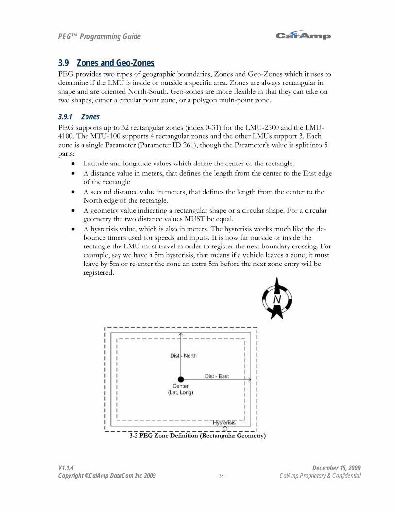
PEG™ Programming Guide
V1.1.4 December 15, 2009 Copyright ©CalAmp DataCom Inc 2009 - 36 - CalAmp Proprietary & Confidential
3.9 PEG provides two types of geographic boundaries, Zones and Geo-Zones which it uses to determine if the LMU is inside or outside a specific area. Zones are always rectangular in shape and are oriented North-South. Geo-zones are more flexible in that they can take on two shapes, either a circular point zone, or a polygon multi-point zone.
Zones and Geo-Zones
3.9.1 Zones PEG supports up to 32 rectangular zones (index 0-31) for the LMU-2500 and the LMU-4100. The MTU-100 supports 4 rectangular zones and the other LMUs support 3. Each zone is a single Parameter (Parameter ID 261), though the Parameter’s value is split into 5 parts:
• Latitude and longitude values which define the center of the rectangle. • A distance value in meters, that defines the length from the center to the East edge
of the rectangle • A second distance value in meters, that defines the length from the center to the
North edge of the rectangle. • A geometry value indicating a rectangular shape or a circular shape. For a circular
geometry the two distance values MUST be equal. • A hysterisis value, which is also in meters. The hysterisis works much like the de-
bounce timers used for speeds and inputs. It is how far outside or inside the rectangle the LMU must travel in order to register the next boundary crossing. For example, say we have a 5m hysterisis, that means if a vehicle leaves a zone, it must leave by 5m or re-enter the zone an extra 5m before the next zone entry will be registered.
3-2 PEG Zone Definition (Rectangular Geometry)

PEG™ Programming Guide
V1.1.4 December 15, 2009 Copyright ©CalAmp DataCom Inc 2009 - 37 - CalAmp Proprietary & Confidential
Figure 3-3 PEG Zone Definition (Circular Geometry)
3-4 Example of PEG Zone Crossing

PEG™ Programming Guide
V1.1.4 December 15, 2009 Copyright ©CalAmp DataCom Inc 2009 - 38 - CalAmp Proprietary & Confidential
3.9.1.1 Using Zones PEG zones are used to detect when a vehicle enters or leaves a specific area. To support this, PEG has 4 Zone Triggers 2 Zone Conditions and 4 Zone Actions. The Triggers used for Zones are:
• Zone Entry: This Trigger occurs when the vehicle enters into a specific PEG Zone. The Zone is specified by the Trigger Modifier (i.e. zone 0 -31).
• Zone Exit: This Trigger occurs when the vehicle leaves a specific PEG Zone. Again, the Zone is specified by the associated Trigger Modifier (i.e. zone 0 -31).
• Any Zone Entry: This Trigger occurs when the vehicles enters any of the defined Zones. Note that if the vehicle enters multiple Zones at the same time an Any Zone Entry Trigger will be fired for each Zone
• Any Zone Exit: This Trigger occurs when the vehicle leaves any one of the PEG Zones.
The Conditions used for Zones are:
• Zone State: This Condition is used to test if the LMU is inside or outside a specific Zone. The Condition Modifier defines what state to test (Inside or Outside) and what Zone to test against. Bits 0 thru 6 dictate which Zone to monitor (0-31). Bit 7 of the Condition Modifier indicates the desired Zone State. If Bit 7 is set, then the Condition is true of the LMU is Outside the Zone. If Bit 7 is cleared, then the Condition is true if the LMU is Inside the Zone.
• Zone Enabled: This Condition is true if the Zone specified by the Condition Modifier is enabled. It is false if the Zone is disabled. The Condition Modifier ranges from 0-31.
The following PEG Actions make use of PEG Zones
• Move Zone States to Accumulator: This Action allows a PEG script to report the current state of all 32 PEG Zones via an Accumulator. If the LMU is inside a PEG Zone, the corresponding bit is set. That is, if the LMU is in Zone 1 and 2 then bits 1 and 2 will be set, thus the value of the Accumulator will be 6. The Action Modifier indicates which Accumulator to place the zone states in.
• Set Zone: This Action will set the center latitude and center longitude value of the PEG zone indicated by the Trigger Modifier to the current position of the LMU.
• Disable Zone: Zones, by default are enabled. When a zone is disabled it no longer produces Zone Entry or Exit Triggers. This is the same effect as defining a 0m East and North distance in the Parameter. The Action Modifier defines which zone (0-31) to disable.
• Enable Zone: This Action will re-enable a disabled zone. When a disabled zone is re-enabled an immediate Zone Entry or Zone Exit Trigger should occur. The Action Modifier defines which zone (0-31) to enable.

PEG™ Programming Guide
V1.1.4 December 15, 2009 Copyright ©CalAmp DataCom Inc 2009 - 39 - CalAmp Proprietary & Confidential
3.9.2 Geo Zones Geo-Zones were created to be more flexible than the PEG Zones allowing users to create complex shapes or define more than 32 boundaries. There are two types of Geo-Zones, a Point Zone and a Polygon Zone. Point Zones are much like PEG Zones but they are circular in shape instead of rectangular. They are defined by a center point and a radius. Unlike PEG Zones, they do not have a hysterisis. Polygon Zones are Zones with 3 or more vertices and can be placed in any orientation unlike the North-South orientation of the PEG Zones. Like the Point Zones, they do not have a hysterisis. Geo-Zones are only supported on the LMU-4100™ product.

PEG™ Programming Guide
V1.1.4 December 15, 2009 Copyright ©CalAmp DataCom Inc 2009 - 40 - CalAmp Proprietary & Confidential
3.9.2.1 Defining Geo-Zones As mentioned there are two supported types of Geo-Zones, a Point zone which has a Type value of 1 and a Polygon zone, which has a type value of 2. Each Geo-Zone within the LMU is made up of one or more Records. The Records are further sub-divided into 6 pieces:
• Zone Type: A Type of 1 indicates the Record is a a Point Zone and Type of 2 indicates the Record is part of a Polygon Zone.
• Super Group: The Super Group is one of two values used to identify a Geo-Zone. Super Group values may range from 0-3.
• Group ID: Group IDs sit under Super Groups and together uniquely identify a Geo-Zone. There may be up to 256 Groups within a Super Group. Group values may range from 0 – 255.
• Latitude: The latitude value of either the center of the Point Zone or the location of the Polygon Zone’s vertex.
• Longitude: The longitude value of either the center of the Point Zone or the location of the Polygon Zone’s vertex.
• Range: The range is only used for Point Zones and defines the radius of the Point Zone.
3-5 Point Zone Definition

PEG™ Programming Guide
V1.1.4 December 15, 2009 Copyright ©CalAmp DataCom Inc 2009 - 41 - CalAmp Proprietary & Confidential
3-6 Polygon Zone Definition
3.9.2.2 Programming Geo-Zones Programming Geo-Zones is not like programming the other settings within PEG since the Geo-Zone record is not a Parameter. Geo-Zones are actually stored in the LMU’s onboard flash memory, so some unique steps must be taken to program things correctly. First the order in which the Records are programmed is very important, especially for Polygon Zones. Records must be listed in either clock-wise or counter-clockwise order as you travel around the perimeter of the polygon. The first record of the polygon is also used as the last. Polygons points must appear in successive definitions, for instance, if you have a 6 point polygon and a 12 point polygon, the first 6 records must be polygon #1, the next 12 must be polygon #2. Polygon zones cannot share points. Point Zones, since they are stand-alone entities may appear in any order and in any combination. Keep in mind that Point Zones and Polygon Zone definitions must be kept separate from each other. That is, a Point Zone Record must not appear within a list of Records defining a Polygon Zone. The LMU-4100 can store up to 5400 Geo-Zone Records (i.e. 5400 points or vertices over multiple Geo-Zones). Geo-Zones can be programmed in to the LMU in one of two ways, either by an AT Command, or via a series of LM Direct messages. The LM Direct method is described in the LM Direct Reference Guide. The AT Command method is described here. The first step in programming Geo-Zones is to clear out any previous definitions. This is done with the AT Command AT$APP GZ ERASE. From there each point must be individually programmed. This is done via the AT$APP GZ WRITE AT Command The GZ write command takes 6 fields.
PEG™ Programming Guide
V1.1.4 December 15, 2009 Copyright ©CalAmp DataCom Inc 2009 - 42 - CalAmp Proprietary & Confidential
• Record Index: 0-5399. This is the Records positioning in flash memory. It is good practice to write records in record index order (i.e. write record index 0, followed by 1 then 2, etc…)
• Type: The Type value is split into two parts, one that defines the Geo-Zone type, the other defines the Super Group. Bits 4 – 7 = Super Group (0-3) Bits 0 – 3 = Type (1, 2)
• Group ID: 0-255. This is the Geo-Zone’s ID value. • Range: (0-65535). The range value is only used for Point Zones and defines the
radius of the Point Zone’s circle in meters. • Latitude: Defines the latitude of the Geo-Zone record • Longitude: Defines the longitude of the Geo-Zone record
As an example, the following command would be used to program a Point Zone into the 0th index with a center point on the Alamo with a 1 mile radius. This zone will be in super group 3 and have a Group ID of 12.
AT$APP GZ WRITE 0 49 12 1619 29.425720 -98.485041 AT$APP GZ WRITE <record index> <super group and type> <group id> <latitude> <longitude>
Geo-Zones are processed in Record Index order.
3.9.2.3 Using Geo-Zones Geo-Zones, like the PEG Zones, have four associated Triggers indicating when the LMU crossed a zone boundary and in which direction, either entry or exit. The Triggers are
• Geo-Zone Entry: This Trigger occurs when the vehicle enters into a specific Geo Zone. The ID of the Geo-Zone must match the value in the Trigger Modifier. Please note that this Trigger is not filtered on Super Group. This means that 4 different zones can produce this Trigger. (i.e. zone ID X Super Group 0, 1, 2 and 3)
• Geo-Zone Exit: This Trigger occurs when the vehicle leaves a specific Geo Zone. The ID of the Geo-Zone must match the value in the Trigger Modifier. Please note that this Trigger is not filtered on Super Group. This means that 4 different zones can produce this Trigger. (i.e. zone ID X Super Group 0, 1, 2 and 3)
• Any Geo-Zone Entry: This Trigger occurs when the vehicles enters any of the defined geo-zones. Note that if the vehicle enters multiple geo-zones at the same time then the same number of Any Geo Zone Entry Triggers will be fired.
• Any Zone Exit: This Trigger occurs when the vehicles exits any of the defined geo-zones. Note that if the vehicle leaves multiple geo-zones at the same time then the same number of Any Geo Zone Entry Triggers will be fired.
As noted above, the Geo-Zone Entry and Exit Events cannot be filtered by Super Group. To accomplish this, the PEG Event must also contain the Super Group Condition. This Condition will only be true if the Super Group value of the Geo-Zone crossed matches the value in the Condition Modifier.

PEG™ Programming Guide
V1.1.4 December 15, 2009 Copyright ©CalAmp DataCom Inc 2009 - 43 - CalAmp Proprietary & Confidential
Again, like the Zones, there is only one available Action in relation to Geo-Zones.
• Start Geo-Zone Accumulation: This Action will place the Super Group and ID values of the last Geo-Zone boundary crossed in the Accumulator specified by the Action Modifier (0-15). The following formatting is used on the Accumulator:
Bits 0-7 contain the Geo-Zone ID (0-255) Bits 8-15 contain the Super-group ID (0-3) Bits 16-23 contain the Geo-Zone’s Type (1 or 2) Bits 24-31 indicate if it was an Enter (1) or Exit (0) Event.
For example, if a vehicle left the Alamo Point Zone defined above, the Accumulator value would be 4882.
4882 = 0x00 01 03 0C 00 = Exit 01 = Point Zone 03 = Super Group 3 0C = ID 12
In the case of multiple crossings, the values of the last Geo-Zone crossing processed will be used.

PEG™ Programming Guide
V1.1.4 December 15, 2009 Copyright ©CalAmp DataCom Inc 2009 - 44 - CalAmp Proprietary & Confidential
3.10 The LMU supports a variety of ‘Text Messages’. These LMU’s Text Messages are custom strings which can be sent from the LMU through a variety of paths. While SMS is one of the ways in which the LMU can send its ‘Text Messages’, they are not limited to this path.
Text Messages
The LMU supports 4 types of ‘Text Message’.
• A generic Short Text Message • A generic Long Text Message • A Status Message • A Position Message
3.10.1 Generic Messages The LMU supports two types of generic Text Messages, long messages, which can be 63 characters long (Parameter 2176), or short messages which can be 15 characters long (Parameter 2177). For the LMU-2500 and LMU-41000, there are 8 long messages (indexes 0-7) and 16 short messages (0-15). The other LMU products only support a single Short Message. Messages can be sent to one of 4 possible destinations, the SMS Inbound address, the LMU’s Host port, the LMU’s Modem port and the LMU’s Aux Port using either the Send Short Text Message or Send Long Text Message Actions. The Action Modifier for both of these Actions are split into 3 parts, the first indicates which message to use, the second dictates with path to use and the last describes any additional message formatting. The formatting section uses bits 6 and 7. If bit 7 is set, then a Carriage Return character is appended to the end of the text message. If bit 6 is set, then a Line Feed character is appended to the end of the text message. The path section uses bits 4 and 5. The following settings are available:
Bit 5 State Bit 4 State Path Set Set SMS Inbound Set Cleared Aux Port8
Cleared
Set Modem Port Cleared Cleared Host Port
Lastly, the message selection is handled by bits 0 thru 3. The values of these bits indicate which index to pull the message from (index 0-15 for short messages and index 0-7 for long messages). As an example, if we want to send long text message 6 to the Aux Port including the CR character, the Action Modifier would be 182 (0xB6 => 1 0 11 0110) Additional formatting can be applied to the text messages by use of the Set Text Attributes Action. There are 4 additional formatting options available. Each option is enabled or disabled by clearing a specific bit in the Action Modifier. The bit mappings are as follows:
8 In order to use the Aux Port, the ioPod must be attached.
PEG™ Programming Guide
V1.1.4 December 15, 2009 Copyright ©CalAmp DataCom Inc 2009 - 45 - CalAmp Proprietary & Confidential
Bit 3 = Local(1) vs GMT (0) timestamp Bit 2 = Add Date Bit 1 = Add Time (See Bit 3 for GMT Offset) Bit 0 = Mobile ID
3.10.2 Status Messages In addition to generic Text Messages, the LMU supports a Status Message. This message is formatted as follows:
COM:<rssi> [unit's IP address (if valid connection)] GPS:[Antenna <Short/Open/Off>] | [No Time Sync] | [<FixStatus> <Sat Count>] INP:<inputs states (binary,MSBit first)> <vehicle voltage> MID:<mobile ID> <mobile ID type> INB:<inbound IP address>:<inbound port> <Inbound Protocol (LMD/LMX)>
The fields in the message contain the following information:
• COM: o <rssi> The RSSI of the wireless modem. IF the value is -113 then it is likely
the LMU is unable to communicate with the wireless device. o [unit’s IP address (if valid connection)]: This field will contain the IP
address assigned to the LMU by the wireless network. • GPS:
o [Antenna <Short/Open/Off>] | [No Time Sync] | [<FixStatus> <Sat Count>]: This field contains the state of the GPS receiver and its contents will change based on that state. If there is a problem with the GPS receiver’s antenna then you will get the [Antenna <Short/Open/Off>] field. Short indicates the antenna’s cable has been crushed, Open indicates that the antenna is not connected and Off indicates the GPS receiver is off. If [No Time Sync] appears, then the antenna is okay, but the GPS receiver has not found any usable GPS signals. Lastly, if you get the [<FixStatus> <Sat Count>] field, it indicates that the GPS has or had a good fix (2D or 3D) and how many satellites it used.
• INP: o <inputs states (binary,MSBit first)>: This field contains the states of all
the available inputs on the LMU. The first 1 or 0 value indicates input 7 where the last indicates the ignition (input 0). If the value is a 1 then the input is high, if it is 0 the input is low.
o <vehicle voltage>: This field reports the voltage seen by the LMU’s internal A/D input. The value is in mV
• MID: o <mobile ID>: This field should contain the Mobile ID currently being used
by the LMU

PEG™ Programming Guide
V1.1.4 December 15, 2009 Copyright ©CalAmp DataCom Inc 2009 - 46 - CalAmp Proprietary & Confidential
o <mobile ID type>: This field indicates the type of Mobile ID being used. This can be OFF, ESN, IMEI, IMSI, MIN or USER
• INB o <inbound IP address>:<inbound port>: This field contains the inbound
IP address and port currently being used by the LMU. o <Inbound Protocol (LMD/LMX)>: This field indicates which protocol is
being used for inbound messages, either LM Direct (LMD) or LM eXchange (LMX).
PEG can force the LMU to create Status Message using the Send Text Status Message Action. Like the Send Short Text Message and Send Long Text Message Actions, the status message can be sent to any of the available paths. Again, the Action Modifier defines which path and formatting to use. The formatting section uses bits 6 and 7. If bit 7 is set, then a Carriage Return character is appended to the end of the text message. If bit 6 is set, then a Line Feed character is appended to the end of the text message. The path section uses bits 4 and 5. Lastly, bits 0 thru 3 are used for a ‘Text Status Type’ field. This is a user defined field which, for instance, could indicate why the message was created. This value can range from 0-15. The Set Text Attributes Action does not apply to this Action.
PEG™ Programming Guide
V1.1.4 December 15, 2009 Copyright ©CalAmp DataCom Inc 2009 - 47 - CalAmp Proprietary & Confidential
3.10.3 Position Messages The last text message supported by PEG uses the Display Position Action. This Action will force either a GPS POS message or an NMEA RMC string to be sent to the host port. Message selection is based on bit 2 of S-Register 156. If this bit is set, then an NMEA RMC string is used. If this bit is cleared then a POS string is used. The POS format is as follows:
POS,<param>,<gps_time_of_fix>,<latitude>,<longitude>,<heading>,<speed>,<HDOP>,<number of satellites> ,<fix status>
• <Param>: This is the Action Modifier for the Display Position Action. • <gps_time_of_fix>: This is the time reported by the GPS receiver in seconds since
00:00:00 of Jan 1 1980. • <latitude>,<longitude>: The latitude and longitude reported by the GPS receiver
in decimal degrees. These values are scaled by 107. • <heading>: The heading reported by the GPS receiver in degrees from true North. • <speed>: The speed of the LMU in Miles Per Hour. • <HDOP>: The Horizontal Dilution of Precision reported by the GPS receiver.
This value is unitless and is scaled by 100. • <number of satellites>: The number of satellites used by the GPS receiver to
produce the fix. • <fix status>: The fix status of the LMU, where fix status is described by:
Bit 0 – Predicted Bit 1 – Differentially Corrected Bit 2 – Last Known Bit 3 – Invalid Fix Bit 4 – 2D Fix Bit 5 – Historic Bit 6 – Invalid Time
PEG™ Programming Guide
V1.1.4 December 15, 2009 Copyright ©CalAmp DataCom Inc 2009 - 48 - CalAmp Proprietary & Confidential
3.11 The LMU supports two type of Binary messages, custom messages and canned messages. The custom messages are user-definable and may be stored in the Long and Short Text String Parameters (i.e. Parameter 2176 and 2177). The canned messages are for specific peripheral devices. At present, the LMU supports two devices for canned messages:
Binary Messages
• The Mackenzie Labs DADS-A1214 In-Vehicle Automatic Announcement System • The Garmin NUVI 760
3.11.1 Using Custom Binary Messages Custom Binary messages are controlled by a single PEG Action, Send Binary. The Action Modifier for this Action dictates three items:
• Bit 6 – This bit dictates which Parameter the binary messages are stored in. If the Bit is set, then the messages should be stored in the Long Text String Parameter (2176). If the bit is cleared, then they are stored in the Short Text String Parameter (2177)
• Bits 4 and 5 – These two bits define which serial port the binary message is sent to. The options are:
o 0 = Host Port o 1 = Modem Port o 2 = Aux Port o 3 = Not Available
• Bits 0-3 – This defines the index of the message to send based on the parameter selected in bit 6.
For the Long and Short Text String Parameters, the Send binary data is represented by hexadecimal characters in text string. For example, if you wished to send the binary message of 10 0A 02 H8 00 EC 10 03 00, you would use a Long Text String (the full string is 18 characters long which is too big for a short string) with the following AT Command:
AT$APP PARAM 2176,5,”100A02H800EC100300” To send this message to the Aux Port you would use an Action Modifier of 101.
Bit 6 = 1 (Long Text String) Bit 5 and 4 = 2 (binary 10) Bits 3-0 = 5 (Index of Text string, binary 0101) Action Modifier = 101 (binary 0110 0101)

PEG™ Programming Guide
V1.1.4 December 15, 2009 Copyright ©CalAmp DataCom Inc 2009 - 49 - CalAmp Proprietary & Confidential
3.11.2 Using Canned Messages As mentioned above, the LMU has a number of canned messages it can use with two specific devices, the Mackenzie Labs DADS-A1214 In-Vehicle Automatic Announcement System and the Garmin NUVI 760. Both the device selection and which port the device is connected to is dictated by S-Register 173. The lower 4 bits dictate the device and the upper 4 bits dictate the destination port. The bit mappings are as follows:
• Bits 4 and 7 – These bits define which serial port the canned message is sent to. The options are:
o 0 = Host Port o 1 = Modem Port o 2 = Aux Port o 3-31 = Reserved
• Bits 0 and 3 – These bits define which device the LMU is connected to. The options are:
o 1 = Mackenzie LABs DADS-A1214 o 2 = Garmin NUVI o 0,3-31 = Reserved
For example, to use the DADS-A1214 on the Aux Port, you would use:
ATS173=33 (0x21) To use the Garmin NUVI on the Host Port, you would use:
ATS173= 2 (0x02) To send messages to these devices, you would use the Send Serial Message PEG Action. The meaning of the Action Modifier changes based on the device selection
3.11.2.1 Mackenzie Labs DADS-A1214 The LMU supports 3 canned messages for the DADS A1214. They are selected based on the Action Modifier of the Send Serial Message Action. The supported messages are:
• Action Modifier = 127 (Set Date Message) • Action Modifier = 126 (Set Time Message) • Action Modifier = 125 (VMS Set Message)
The LMU also supports playback of pre-recorded announcements from the DADS-A1214. For this operation, the Action Modifier is split into two parts, which message to play (as defined by bits 0-6) and which channel to use, Channel 1 or 2 (as defined by Bit 7).
• Bit 7: If Bit 7 is set, then Channel 2 is used. If Bit 7 is cleared then Channel 1 is used • Bits 0-6: Announcement message.
For example to play message 6 on channel 2 you would use an Action Modifier of 134 (0x86)

PEG™ Programming Guide
V1.1.4 December 15, 2009 Copyright ©CalAmp DataCom Inc 2009 - 50 - CalAmp Proprietary & Confidential
3.11.2.2 Garmin NUVI At present, the LMU only supports 3 messages for the Garmin NUVI. They are selected based on the Action Modifier of the Send Serial Message Action. The supported messages are:
• Action Modifier = 127 (Enable Garmin NUVI Fleet Mode) • Action Modifier = 126 (Request Garmin NUVI ID Message) • Action Modifier = 125 (Turn NUVI Off)
It is important to remember that any responses or messages created by the NUVI are sent thru the LMU as User Messages. At this point in time, the Garmin NUVI is only supported on the LMU’s Host Port.

PEG™ Programming Guide
V1.1.4 December 15, 2009 Copyright ©CalAmp DataCom Inc 2009 - 51 - CalAmp Proprietary & Confidential
3.12 PEG Flags are somewhat unique in PEG in that their values can be changed within a script. Flags are Booleans (i.e. they have true or false values) which are generally used to indicate that various Events or conditions have happened.
PEG Flags
There are 16 PEG Flags in all (0-15)
3.12.1 Using PEG Flags PEG Flags only have two states, True (Set) or False (Cleared). PEG supports 3 Actions to report and manipulate these states.
• Set Flag: This Action will set the PEG Flag (0-15) indicated by the Action Modifier to true.
• Clear Flag: This Action will set the PEG Flag (0-15) indicated by the Action Modifier to false.
• Move PEG Flags to Accumulator: This Action will map all 16 PEG Flags to the lower 16 bits of the Accumulator (0-15) specified by the Action Modifier.
In addition to the Actions, PEG also supports 3 Conditions to allow a script to react to Flag States.
• Flag Set: This Condition is true when the flag (0-15) indicated by the Condition Modifier is also true.
• Flag Cleared: This Condition is false when the flag (0-15) indicated by the Condition Modifier is false.
• PEG Flag Compare: This Condition will be true if the states of the lower 8 flags match the states described by the Condition Modifier. The Condition Modifier is bit-mapped, matching a bit with a flag. If the bit is set, then the corresponding flag should be in the true state, if the bit is false then the flag should be in the false state. The bit-mapping is as follows: Bit 0 = Flag 0 Bit 1 = Flag 1 … Bit 7 = Flag 7
PEG does not support any Flag based Triggers.

PEG™ Programming Guide
V1.1.4 December 15, 2009 Copyright ©CalAmp DataCom Inc 2009 - 52 - CalAmp Proprietary & Confidential
3.13 PEG Enables (Parameter 1037) and User Flags (Parameter 1036) are much like PEG Flags in that they are Boolean fields. The difference is that PEG Enables and User Flags are controlled by Parameter settings (i.e. the LMU’s configuration) as opposed to the PEG Script. There is only a single index of each the PEG Enables and User Flags Parameters. The following sections will explain the use of User Flags and PEG Enables.
PEG Enables and User Flags
3.13.1 Using User Flags User Flags were created to allow for multiple configurations within a given PEG Script. For instance, say a client has 3 different types of vehicles. Each of these vehicles should support some of the same features (e.g. Ignition detection, distance accumulation, etc…), however, they also have some unique requirements. By using User Flags within a script, those unique requirements can be turned on and off without having to create and deploy a unique script for every vehicle. There are 4 User Flags in total, which map into the lower 4 bits of Parameter 1036. That is, bit 0 of 1036 is User Flag 0, bit 1 is User Flag 1, bit 2 is User Flag 2 and bit 3 is User Flag 3. User Flags are set and cleared by changing the value of Parameter 1036. PEG only supports 1 Condition to use with User Flags.
• User Flag: This Condition is true when the value of the Condition Modifier describes the states of the User Flags. The Condition Modifier is broken into two parts, a mask, which indicates the bits to monitor, and a value, which indicates the state of the bits. The upper 4 bits are the mask and the lower 4 bits are the value. For example, say the script needs to know if user flags 3 and 1 are true and 2 and 0 are false. The Condition Modifier would be 250 (0xFA = 1111 1010 with F representing the Mask and 1010 the states of the User Flags)
The User Flag Update Unit Request message9
3.13.2 Using PEG Enables
can be used to force a Special Trigger. The Trigger Modifier will match the value of the Special Trigger Number field of the Unit Request message.
PEG Enables were created to extend the number of optional features a PEG script could support. There are 32 PEG Enable flags in total, and, like the User Flags are mapped into the value of Parameter 1037. PEG Enable flag 0 maps to Bit 0, flag 1 maps to bit 1 up to PEG Enable Flag 31 maps to bit 31. The states of the PEG Enable flags are controlled by changing the value of Parameter 1037. Again like User Flags, PEG supports a single Condition to use with PEG Enables:
• PEG Enables: This Condition is true if the PEG Enable Flag indicated by the Condition Modifier (0-31) is also true.
9 See the LM Direct Reference Guide.

PEG™ Programming Guide
V1.1.4 December 15, 2009 Copyright ©CalAmp DataCom Inc 2009 - 53 - CalAmp Proprietary & Confidential
3.14 The PEG State Variable is similar to the PEG Flags in that it is explicitly controlled by the PEG Script and is used to allow you to conditionally exclude or include parts of the script. The only difference is that the PEG State Variable is a single number instead of a Boolean True/False setting. The PEG Variable may range from 0 to 255.
PEG State Variable
There is one PEG Action and one PEG Condition that related to the PEG State Variable. The Action is, Set PEG State, which allows the PEG Script to set the PEG State Variable to a specific value. The Action Modifier is used to control this value and may range from 0 to 255. Please note that if a value is not set, the default is 0. The Condition used with the PEG State Variable is PEG State Compare. If the value of the Condition Modifier is equal to the current value of the PEG State Variable, then the condition is true. If the value of the Condition Modifier is not equal to the value of the PEG State Variable, then the condition is false.

PEG™ Programming Guide
V1.1.4 December 15, 2009 Copyright ©CalAmp DataCom Inc 2009 - 54 - CalAmp Proprietary & Confidential
3.15 At the heart of the LMU is a GPS receiver and thus in addition to location, part of what PEG provides is knowledge about the actual date and time. Specifically PEG uses the Time of Day and the Day of the Week.
Date and Time
The Time of Day is actually broken into two Parameters, the actual time of day (Parameter 267), which is measured in seconds since midnight and a repeat interval (Parameter 268), which is measured in seconds. As an example, these two Parameters would let the PEG script report every hour on the hour. Up to four Time of Day settings can be stored in the LMU. It is important to remember that Index 0 of Parameter 268 is applied to Index 0 of Parameter 267. Like the Time of Day setting, the LMU can store up to 4 Day of Week settings (Index 0-3 for Parameter 269). The Day of Week value is bit mapped indicating which days should be monitored for. Like many of the other bit mapped fields, the value of the Day of Week Parameter is split into two parts, a mask and a value. The mask, which uses the upper 8 bits, indicates which bits to program and the value indicates the state of the bits. The value bit mapping for this Parameter is as follows:
bit 0: Sunday bit 1: Monday bit 2: Tuesday bit 3: Wednesday bit 4: Thursday bit 5: Friday bit 6: Saturday
Both the Day of Week and Time of Day are affected by the Local-Time-Zone setting of the LMU (i.e. Parameter 1030). It is very important to remember that any time reported by the LMU will be in UTC10
3.15.1 Using Date and Time
regardless of the Local-Time-Zone setting. That is, PEG reacts to local time, but it always reports UTC time.
To support date and time knowledge, PEG provides 1 Trigger and 3 Conditions. The single Trigger is:
• Time of Day: This Trigger occurs when the time reported by the GPS receiver matches the Time of Day referenced by the Trigger Modifier (0-3). The associated repeat interval will trigger when the current time’s minute hand is a multiple of the Time of Day Repeat setting offset from the Time of Day Time setting. For example, if the Time of Day is set to 13:03:00, repeat interval is set to 5 minutes with a current time of 12:05:00, the triggers will start at 12:08:01, 12:13:01, 12:18:01, etc. Note that
10 Coordinated Universal Time
PEG™ Programming Guide
V1.1.4 December 15, 2009 Copyright ©CalAmp DataCom Inc 2009 - 55 - CalAmp Proprietary & Confidential
repeat intervals cannot be explicitly stopped until the LMU loses power or goes to sleep.
The available Conditions are:
• Day of Week: This Condition is true if the day reported by the GPS receiver matches one of the days set in the Day of Week Parameter indicated by the Condition Modifier (0-3). For instance, if Day of Week 0 has Mon-Fri check, this Condition would be true during the week and false on the weekends.
• Inside Time of Day Window: This Condition is true if the time reported by the GPS receiver is in the Time of Day Window defined by the Condition Modifier. The Condition Modifier is separated into 4 parts which must be combined to make a single value ranging from 0 -255
bit 0& bit 1 = Starting Time Of Day index (0-3) bit 2 & bit 3 = Starting Day Of Week index (0-3) bit 4 & bit 5 = End Time Of Day index (0-3) bit 6 & bit 7 = End Day Of Week index (0-3)
• Outside Time of Day Window: This Condition is true if the time reported by the GPS receiver is outside of the Time of Day Window defined by the Condition Modifier. The Condition Modifier is separated into 4 parts which must be combined to make a single value ranging from 0 -255
bit 0& bit 1 = Starting Time Of Day index (0-3) bit 2 & bit 3 = Starting Day Of Week index (0-3) bit 4 & bit 5 = End Time Of Day index (0-3) bit 6 & bit 7 = End Day Of Week index (0-3)
For example, to define a window from 9am to 5 pm every Monday thru Friday, you would setup the following:
Parameter 267, Index 0 = 32400 (i.e. 09:00) Parameter 267, Index 1 = 61200 (i.e. 17:00) Parameter 269, Index 2 = 62 (i.e. 0011 1110) Condition Modifier = 152 (i.e 1001 1000)

PEG™ Programming Guide
V1.1.4 December 15, 2009 Copyright ©CalAmp DataCom Inc 2009 - 56 - CalAmp Proprietary & Confidential
3.16 In addition to traditional knowledge like time and distance, PEG also provides information about the state of the GPS receiver. That is, PEG knows if the GPS receiver has a valid time, if it is producing a valid position and can give an estimate on the accuracy of the position.
GPS
3.16.1 Using GPS PEG offers two Triggers, four Conditions and three Actions that work with the GPS receiver. There are two GPS notification Triggers:
• GPS Acquired: This Trigger occurs when the GPS receiver produces a valid GPS position. It occurs once after initial acquisition and once after a GPS loss.
• GPS Lost: This Trigger occurs when the GPS receiver stops producing a valid GPS fix for the amount of time set in the GPS Lost Timeout Parameter (ID = 1027). This is typically 60s.
PEG supports 6 Conditions in relation to GPS. They are as follows:
• Time Valid: This Condition indicates if the GPS receiver has a valid time. The Condition is true if the state of the time (valid or invalid) matches the Condition Modifier. A Condition Modifier of 1 indicates that time should be valid for the Condition to be true. A Condition Modifier of 0 indicates that the time should be invalid for the Condition to be true.
• GPS Acquired: This Condition is true if the GPS receiver is producing a valid 2D or 3D location.
• GPS Not Acquired: This Condition is true if the GPS receiver is not currently producing a valid position.
• Comm and GPS Available: This Condition is true if the GPS receiver is producing a valid position (2D or 3D) and the wireless modem has a data session with the wireless network.
• GPS On: This Condition is true if the LMU’s GPS receiver is powered on. • GPS Fix Quality: This condition is true if the current fix from the GPS receiver is
better than the Fix Quality defined by the Condition Modifier. The available values are:
0 = Threshold Off 1 = Sat Count >= 4 and HDOP <= 3.0 2 = Sat Count >= 4 and HDOP <= 2.0 3 = Sat Count >= 5 and HDOP <= 2.0 4 = Sat Count >= 5 and HDOP <= 1.5 5 = Sat Count >= 6 and HDOP <= 1.5 6 = Sat Count >= 7 and HDOP <= 1.5 7 = Sat Count >= 8 and HDOP <= 1.2 8 = Use threshold defined in S-Register 174

PEG™ Programming Guide
V1.1.4 December 15, 2009 Copyright ©CalAmp DataCom Inc 2009 - 57 - CalAmp Proprietary & Confidential
Two of the available Actions are Power-Up GPS and Power-Down GPS and they do exactly what they say, that is they turn the GPS receiver on and off. If the GPS receiver is already on when a Power-Up GPS Action is performed, the GPS remains on. The third Action that can be performed with the GPS receiver is the Start Position Accuracy Accumulation Action. This Action will place the position accuracy estimate produced by the GPS receiver into the Accumulator specified by the Action Modifier (0-15). This value will be updated with every valid GPS update. If the GPS receiver is not producing a fix, the value will be 999999. All values are in meters.
3.16.1.1 GPS Position Accuracy Accumulator The Position Accuracy value is an accuracy estimate produced by the GPS receiver. Effectively it is the GPS receiver’s guess at how good the position solution (i.e. the Lat/Long) is based on such things as satellite positioning and signal strength. For example, if the GPS Accuracy Estimate is 5m, then the GPS receiver thinks that the actual latitude and longitude is within +/- 5m of the values provided. Please note that the accuracy value is only an estimate of the GPS quality. It is not, nor can it be, an absolute measurement of accuracy.
3.16.1.2 Requesting Time When GPS is not Available It is possible for the LMU to request a time sync when GPS time is not available. This request can be made either to its Inbound Server or its Maintenance Server (PULS). The LMU provides a single PEG Action, Request Time Sync. This action will send an LM Direct Time Sync Application Message (Application Message Type 50) to the server specified by the Action Modifier. An Action Modifier value of 1 will send an Acknowledged request to the Inbound Server where a value of 0 will send an Unacknowledged request to the Maintenance Server. The LMU will only update its time based on this request if the time from the GPS receiver is invalid. Note that the Server the request is made to must support a Time Sync response message (LM Direct Application Message Type 50). Please with the server’s administration that the response message is supported. The format and usage of Time Sync messages are described in the LM Direct Reference Guide.

PEG™ Programming Guide
V1.1.4 December 15, 2009 Copyright ©CalAmp DataCom Inc 2009 - 58 - CalAmp Proprietary & Confidential
3.17 Comm is short for ‘Communications’ and relates to the state of the wireless modem/device used by the LMU. As with the GPS receiver PEG offers a variety of Triggers, Conditions and Actions that report on and affect the behavior of the LMU’s wireless modem.
Comm
3.17.1 Comm Terminology Before getting into the PEG related aspects of Comm, it is worth going over a number of terms and concepts related to Comm. This section is not a review of wireless networking technologies. Those can be found in the LMU Users Guide. The LMU has several states in which the Wireless Modem can pass through. The PEG Triggers and Conditions rely heavily on these states and it is important to understand how they differ.
• Network Available: In this state the wireless modem is on and is scanning for service. It is the first state an LMU will enter.
• Network Service Acquired: In this state, the LMU has found a wireless network. Keep in mind, that this may be a voice network (eg GSM instead of GPRS).
• Data Service Acquired: After finding a network, the LMU has also detected an available data service. The LMU will attempt to connect to the data service.
• Data Service Connected (Comm Connected): Assuming the connection is successful the LMU will obtain an IP Address. Once that occurs, the LMU is in the Connected state. Keep in mind that it is possible for the LMU to lose one of the above states while connected.
• Comm Available: Comm available indicates that the LMU is connected to a wireless network’s data service and most importantly, is ready to transmit. It is the latter point that distinguishes this state from the Comm Connected state.
In addition to its own Comm states, the LMU supports a number of call states, though much of it is technology dependant. First the LMU can detect two call types, data calls and voice calls. Under normal circumstances, the LMU will always attempt to maintain a data call. The LMU CANNOT place a voice call, though it can detect an incoming call. Within the call types, there are 4 states the LMU supports. They are, Idle, Incoming, Calling and Active. For a call placed by the LMU, it will go from the Idle state, to the Calling state, and, if successful, to the Active state. Again, this only applies to data calls. For an incoming data call (i.e. when the network has data for the LMU) the LMU will go from the Incoming state to active state. Incoming voice calls will go from the Incoming state to the Idle state as the LMU has no means to answer a voice call. The other important concept to keep in mind is that of a Comm Profile. A Comm Profile defines the dial string, network username, network password and inbound settings the LMU will use. The dial string, network username and network password are all used by the

PEG™ Programming Guide
V1.1.4 December 15, 2009 Copyright ©CalAmp DataCom Inc 2009 - 59 - CalAmp Proprietary & Confidential
wireless modem to establish the data service connection. The inbound settings dictate where the LMU will send its data11
3.17.2 Using Comm
.
There are a variety of Triggers, Conditions and Actions within PEG that support the various comm. functions. We will start with the Actions.
• Comm Connect: This Action forces the LMU to re-initialize communications with the wireless modem. It only applies if Comm is already disconnected. Please note that the Action does not power cycle the modem12
• Comm Disconnect: This Action forces the modem to drop its data connection. Comm will not be re-established until Comm is explicitly connected or the LMU is reset.
.
• Power Down Modem: This Action forces the modem to disconnect from the data service and power down.
• Power Up Modem: This Action will power the wireless modem on. If the modem is already on, then it will be reset. The act of resetting the modem will cause the modem to disconnect from its data service. The LMU will attempt to reconnect to the data services after the modem has reset.
• Select Comm Profile: This Action will select the Comm Profile for the LMU to use. By default the LMU uses profile 0. The Action Modifier dictates which profile to use. It is separated into two fields, the Comm settings and the Inbound field. The Comm settings choose which modem, dial string, username and password to use. The inbound field selects which inbound address, port and URL to use. The fields are mapped as follows: Bit 15 – Bit 8 = Comm Settings
1 = Dial String 1, Username 1, Password 1 and Modem S150 0 = Dial String 0, Username 0, Password 0 and Modem S120
Bit 7 – Bit 0 = Inbound Address 3 = Inbound Address 3 2 = Inbound Address 2 1 = Inbound Address 1 and Inbound URL 1 0 = Inbound Address 0 and Inbound URL 0
For instance, to select dial string 1 for use with inbound address 3, the Action Modifier would be set to 19 (0x13)
Primarily, the LMU will post a Comm based Trigger on a state change. The available Trigger points are:
• Comm Acquired: This Trigger occurs when the LMU successfully establishes a data session and is ready to transmit data. The LMU must transition to the Comm Lost state before another Comm Acquired will occur.
11 This is LM Direct data. Any SMS reports are sent via to the SMS Destination address regardless of the inbound settings. 12 Of course, if the LMU is unable to communicate with the wireless modem, the LMU will reset it.
PEG™ Programming Guide
V1.1.4 December 15, 2009 Copyright ©CalAmp DataCom Inc 2009 - 60 - CalAmp Proprietary & Confidential
• Comm Lost: This Trigger occurs when the LMU loses its data connection with the wireless network and is unable to transmit.
• Comm Shutdown: This Trigger occurs when the wireless modem is powered off. • Comm Connected: This Trigger occurs when the modem obtains an IP address
from the wireless network. • Comm State Change: This Trigger occurs when the LMU changes to/from any of
the defined Comm states described above. • Incoming Call: The Incoming Call Trigger occurs when the LMU receives a voice
call. This Trigger can be filtered by using the Caller ID String Parameter (2323). If a filter is used, then the Trigger only occurs if the phone number of the incoming call matches the value in the Caller ID String Parameter.
• Call State Change: This Trigger occurs when the LMU changes call state (Idle, Incoming, Calling, Active).The Trigger Modifier defines which state the LMU is transitioning to.
0 = Call is Idle 1 = Incoming Call 2 = Calling 3 = Active
Note that the LMU only periodically queries the wireless modem for call states and thus it is possible for the LMU to miss a transition. Call state change Triggers will not be posted if that happens.
• Network ID Change: This Trigger occurs when the LMU detects that it has changed networks. For CDMA devices, this is when a new SID is detected. For GSM devices, this is when a new MCC and MNC are detected. Please note that carrier IDs of 0 are ignored.
Condition wise, PEG offers the following to help manage Comm:
• Comm Available: This Condition is true if the LMU has a data session and is ready to transmit data.
• Comm Not Available: This Condition is true if the LMU does not have a valid data session or is otherwise unable to transmit data.
• Comm and GPS Available: This Condition is true if the LMU has a data session and the GPS receiver is producing a valid fix.
• Comm State: This Condition is true if the Comm State of the LMU matches the state described by the Condition Modifier. The Condition Modifier is split into two fields, a mask and state. Bit 7 -4 = Mask
Bit 7 = Monitor Data Service Connected Bit 6 = Monitor Data Service Available Bit 5 = Monitor Network Service Acquired Bit 4 = Monitor Network Service available
Bit 3 – 0 = States Bit 3 = Data Service Connected Bit 2 = Data Service Available Bit 1 = Network Service Acquired Bit 0 = Network Available
PEG™ Programming Guide
V1.1.4 December 15, 2009 Copyright ©CalAmp DataCom Inc 2009 - 61 - CalAmp Proprietary & Confidential
• Comm Select: This Condition is true if the LMU is currently using the Comm
Profile described by the Condition Modifier. The Condition Modifier is split into the Comm Index and the Inbound Index. Bit 7 – 4 = Comm Index (0-1) Bit 3 – 0 = Inbound Index (0-3) As an example, to see if Comm Index 0 and Inbound address 3 are in use you would use a Condition Modifier of 19 (0x13)
• Call Status: This Condition is true if the state of the wireless modem matches the state described by the Condition Modifier. Bit 4 – 7 = Mask Bit 7 & 6 (both set) = Monitor Call Type
Bit 5 &4 (both set) = Monitor Call State Bit 2 & 3 = Call Type
0 = voice 1 = data
Bit 0 & 1 = Call State 0 = idle 1 = incoming 2 = calling 3 = active
As an example, to monitor for an incoming voice call, the Condition Modifier would be set to 241 (0xF1 = 1111 00 01)
• Roaming: This Condition is true if the wireless modem indicates that it is roaming. Be advised that roaming may mean different things according to the operator and billing plan being used. In some cases it can mean that the device is using another operator’s network, or that it is outside its home network (i.e. The LMU has a Dallas number but is currently operating in San Diego but is on the same operator’s network)
• Comm On: This Condition is true if the LMU’s wireless modem is powered on.
3.17.3 Using Voice Calls The iDEN LMU-4100 supports the dialing, answering and hanging-up of voice calls via PEG. The following three Actions are available:
• Dial Voice: This Action forces the LMU to dial a phone number. The Action Modifier indicates what that phone number should be. Phone numbers are stored in the Short Text Message Parameter (Parameter 2177) so the Action Modifier ranges from 0-15.
• Answer: This Action forces the LMU to answer an incoming voice call. • Hang-Up: This Action forces the LMU to disconnect from the active voice call. It
does not have an effect on the data session. All LMUs support the detection of an incoming voice call. An incoming call is indicated by the Incoming Call Trigger. While this Trigger does not have an associated Trigger Modifier, it is controlled by a filter. If the incoming call matches the value in the Caller ID String

PEG™ Programming Guide
V1.1.4 December 15, 2009 Copyright ©CalAmp DataCom Inc 2009 - 62 - CalAmp Proprietary & Confidential
(Parameter 2323) then the Incoming Call Trigger will occur. If not, then the Incoming Call Trigger is suppressed. If the Caller ID String is set to null (i.e. 0), then all incoming calls will produce the Incoming Call Trigger.
3.18 In general LMUs are installed in an environment with a limited power supply (i.e. vehicle batteries) and care must be taken to maximize the life of that power supply. PEG offers a variety of means of controlling the LMU’s power, though typically everything is handled via Sleep.
Power Management
3.18.1 Using Power Management The main component of power management in the LMU is a function known as Sleep. Sleep is a low power mode that effectively suspends all LMU activity13
until a predetermined Event occurs. This Event could be a certain length of time elapsing, a certain time of day being reached or an input transition.
The LMU offers two forms of sleep controlled by Bit 2 of S-Register S-171. Normal Sleep is a mode in which both the GPS Receiver and Wireless Modem within the LMU are turned off. This mode provides the lowest power draw the LMU is capable of. It is enabled if Bit 2 of S 171 is cleared. The second sleep mode will leave the radio on but in a stand-by mode. This latter mode allows a user to remotely wake the LMU via an SMS message but will draw noticeably more power. It is enabled by setting Bit 2 of S-171. The LMU also offers the ability to turn the GPS receiver and wireless modem on and off. While these do offer some measure of power savings, they do not provide nearly the same benefit as sleep. It is almost always recommended that a PEG script contain some measure of sleep function. Also be advised that the modem in the LMU-1000 cannot be turned off as it hosts the LMU application/firmware. For Power Management, the LMU offers the following Actions.
• Sleep (Timer): This Action forces the LMU to Sleep for a specific period of time. The Trigger Modifier for this Action will be a Timer Timeout Index (i.e. Parameter 265). If the referenced timer is 0, the LMU will go to Sleep indefinitely. It will only wake-up on an input transition
• Sleep Until Time of Day: This Action will force the LMU to Sleep until a particular Time of Day. The Action Modifier references a Time-of-Day index (Parameter 267). Please note that this Action does not make use of the Time of Day’s repeat value.
• Application Restart: This PEG Action forces the LMU to shut down and restart. The LMU will power back up a few moments after this Action is issued. The LMU undergoes a similar process at the end of an Over-The-Air firmware download.
• Hibernate: This PEG Action will force the LMU to go to sleep an only wake up when certain inputs transition. The inputs the LMU will monitor are defined by the
13 The modem is turned off, the GPS receiver is turned off and the LMU’s application is put in standby. Nothing can happen while the LMU is sleeping.

PEG™ Programming Guide
V1.1.4 December 15, 2009 Copyright ©CalAmp DataCom Inc 2009 - 63 - CalAmp Proprietary & Confidential
Action Modifier. If a bit of the Action Modifier is set, then the associated input will wake the LMU. If the bit is cleared, then the input will be ignored while the LMU is sleeping. The bit mapping is as follows:
o Bit 0 = Input 0 / Ignition o Bit 1 = Input 1 o Bit 2 = Input 2 o Bit 3 = Input 3 o Bit 4 = Input 4 o Bit 5 = Input 5 o Bit 6 = Input 6 o Bit 7 = Input 7
Each of the Triggers offered by the LMU for power management relate to when the LMU turns on. This can either be when the LMU is initially powered up or when it wakes up from Sleeping.
• Power Up: This Trigger occurs when the LMU is initially powered up. This is also known as a cold start.
• Wake Up: This Trigger occurs when the LMU wakes from a Sleep cycle. • Power Up or Wake Up: This Trigger occurs when the LMU either wakes from
Sleep or is cold started. • Wake Up on Input: This Trigger occurs when the LMU wakes up due to an input
transition. This Trigger does not indicate which input caused the wake up. • Wake Up on Timer: This Trigger occurs when the LMU wakes due to a timer
expiration (i.e. it is coupled to the Sleep (Timer) Action). It does not provide any indication of which timer caused the wake up.
The LMU offers a single Condition in relation to power management, namely the Boot Reason Condition. This Condition is true if the last power up was due to the reason indicated by the Condition Modifier. The supported reasons are:
0 = Cold Boot / Normal Power Up 1 = Power On - Factory Boot 2 = Reset due to OTA Download Complete 3 = Reset due to Radio Power Up 4 = Wake Due to I/O activity 5 = Wake due to Timer 6 = Wake due to an incoming SMS message 7 = Wake due to Application Restart PEG Action or AT Command (ie AT$APP QUIT)
Users should be aware that the state of each Input is captured when the LMU goes to sleep so that after wake up a corresponding Input Trigger will be fired if the input is no longer present or has changed state.

PEG™ Programming Guide
V1.1.4 December 15, 2009 Copyright ©CalAmp DataCom Inc 2009 - 64 - CalAmp Proprietary & Confidential
3.19 In addition to being able to send data via SMS (i.e. Event reports and text messages), the LMU can react to incoming SMS messages. Specifically the LMU knows when it receives an SMS Request (i.e. a !R<x> message) or an empty SMS message. PEG supports the following two Triggers.
SMS
• SMS Request Received: This Trigger will occur when the LMU receives one of
the known SMS Request messages. The Trigger Modifier defines which Request message to look for. The valid range is from 0 – 9.
• NULL SMS Message Received: This Trigger occurs when the LMU receives an empty SMS message (i.e. no contents in the body). The Trigger Modifier is not used and should be set to 0. Please note that some operators block null SMS messages.

PEG™ Programming Guide
V1.1.4 December 15, 2009 Copyright ©CalAmp DataCom Inc 2009 - 65 - CalAmp Proprietary & Confidential
3.20 PEG Environments are a pre-determined set of modules within the LMU that can be monitored en-mass within PEG. This effectively allows users to create more complex Conditions without having to use multiple Events within the PEG script. A PEG Environment monitors for the following:
PEG Environments
• Moving/Not Moving • Log Active/In Active • Comm Acquired/Not Acquired • GPS Available/Not Available • Input 3, 2, 1 and 0(Ignition) High or Low • Day of the Week 0-3 • Speed Above/ Below index 0-3 • Inside/Outside PEG Zone 0-5 • PEG Flag 0-7 Set or Cleared.
Environments are set up using Parameter 273. Each Bit in the Parameter represents a different module to monitor. The specific break-down of bits to modules is listed in the Parameter Definition Appendix of this document. Depending on which PEG item (Trigger or Condition) is used, the setting may also define the state of the module. The states are defined as follows:
Environment Bit Set Environment Bit Cleared Moving Not Moving Log Active Log Inactive Comm Acquired Comm Not Acquired GPS Available GPS Not Available Input High Input Low Is Day of Week Is Not Day of Week Speed Above Speed Below Inside Zone Outside Zone PEG Flag Set PEG Flag Cleared
PEG Environments are only supported by the LMU-4100 and LMU-2500
3.20.1 Using Environments There are three PEG features centered on Environments, one Trigger and two Conditions. The PEG Trigger is the Environment Change Trigger. For this Trigger, the Environment Parameter is used as a monitor. If any of the monitored items changes state, then the Environment Change Trigger occurs. The Trigger Modifier defines which environment to look at (0-7). The two environment Conditions are:
• Environment: Like the Environment Change Trigger, this Condition used the environment Parameter as a monitor. If any of the bits in the monitor are set then the Environment Condition is true. The Condition Modifier defines which environment to monitor.

PEG™ Programming Guide
V1.1.4 December 15, 2009 Copyright ©CalAmp DataCom Inc 2009 - 66 - CalAmp Proprietary & Confidential
• Environment Equate: This Condition is used to monitor for a specific environment state. It is only true when the LMU’s state matches the state of the environment defined in the Condition Modifier. Environments in this case are used in pairs (0 & 4, 1 & 5, 2 & 6 and 3 & 7). The first Environment (0-3) is used to define which modules to look at. The second Environment (4-7) defines the state of each item. The Condition Modifier defines which of these pairs to use (0-3).
PEG™ Programming Guide
V1.1.4 December 15, 2009 Copyright ©CalAmp DataCom Inc 2009 - 67 - CalAmp Proprietary & Confidential
3.21
3.21.1 NOT Conditions
PEG Multiple Condition Management
For the most part Conditions occur in pairs (Ignition On, Ignition Off, Moving, Not Moving, etc…) however, there are some that are stand alone (PEG Flag Compare, Comm Select, Roaming, etc). With these stand alone Conditions, it is sometimes useful to test for the negative of that Condition. For instance, it may be useful to know when the LMU’s wireless modem is not Roaming. In order to accomplish this, PEG offers the ability to invert a Condition using a NOT feature. This Logical NOT operation may be applied to a Condition via the most-significant bit of its Condition Code. (For example, Not Ignition On uses a Condition Code of 129)
3.21.2 Combining Conditions All PEG Events support two Conditions, however, if two are defined, they must be combined in order to create a single True/False result. Most programming languages, including PEG, offer Boolean AND and OR operations to combine True/False results. Bit 6 of the Condition Code determines how Condition one and Condition two are used. If bit 6 is set, then Condition One and Two are combined in a Logical OR operation. If bit 6 is cleared then Condition One and Two are combined in a Logical AND operation. Bit 6 should be changed for both Condition Code one and Condition Code two. As a reminder, the following two truth tables describe how AND and OR operations work.
Condition One Result Condition Two Result OR Result False False False False True True True False True True True True
Condition One Result Condition Two Result AND Result False False False False True False True False False True True True
PEG™ Programming Guide
V1.1.4 December 15, 2009 Copyright ©CalAmp DataCom Inc 2009 - 68 - CalAmp Proprietary & Confidential
3.22 Most programming languages offer some means to create functions and skip parts of the code (think function calls and the GOTO statement). PEG offers similar functionality in the form of four PEG Actions, END, JUMP, CALL and RETURN.
PEG Functions
3.22.1 END The End Action is used to stop the script before it reaches the end of the Event list. One common use for END is as a means to protect an area of the PEG script used to house any ‘functions’.
3.22.2 JUMP The Jump Action allows PEG to jump forward (but not backward) in the Event List. This lets users skip over parts of the PEG script. The Action Modifier for the Jump Action indicates which Event index the script should jump to. This feature is akin to the GOTO statement found in many programming languages.
3.22.3 CALL and RETURN The Call and Return Actions are used to create functions. The Call statement is similar to the Jump statement in that it allows a PEG script to jump forward in the script. The main difference is that the calling Event index is remembered. When a Return Action is encountered, the script will return to the next Event after the one that contains the Call Action. Like Jump, Call’s Action Modifier references the Event index to move to. Return does not require an Action Modifier. Call and Returns can also be nested up to 8 calls deep. That is, you can issue 8 call Actions followed by 8 return Actions and the script will eventually end back at the initial call Event.
3.22.4 Any Trigger The Any Trigger occurs when any other PEG Trigger occurs. Any Triggers can be thought of as a ‘Don’t Care’ operation. That is, it doesn’t matter what happens, but you want the LMU to check for something (i.e. a Condition) and do something (Action).

PEG™ Programming Guide
V1.1.4 December 15, 2009 Copyright ©CalAmp DataCom Inc 2009 - 69 - CalAmp Proprietary & Confidential
3.23 The LMU offers PEG Programmers the ability to know when Over-The-Air changes are taking place. Specifically it allows the programmer to know when either an Over-The Air Firmware update begins and end and when an Over-The Air configuration change begins and ends. Please note that the LM Direct server must implement the Update Begin and Update End Actions within a LM Direct Parameter message in order for the Triggers to work properly.
Over-The Air Changes
The Triggers for this function are Update Begin and Update End. The Trigger Modifier indicates the type of update for both Triggers. A Trigger Modifier value of 0 indicates that a Configuration Update has begun/ended. A Trigger Modifier value of 1 indicates that a Firmware update has begun / ended.
PEG™ Programming Guide
V1.1.4 December 15, 2009 Copyright ©CalAmp DataCom Inc 2009 - 70 - CalAmp Proprietary & Confidential
4 4.1
PEG Programming
There are a number of interpretations of what a PEG Script is. This can range from just the programming of the Event Parameters up to the complete configuration of the LMU. For the purposes of this document, the PEG Script is defined as the list of Events and their associated PEG Parameters (i.e. Accumulators, Timers, Speed Thresholds, etc…).
What is a PEG Script? – A reminder
4.2 Planning a PEG script is much like planning any other piece of software. There are many books, documents and articles on software development processes and ideologies, however the basic steps in each are more or less the same:
Planning a PEG Script
• Collect Requirements – What does the customer want? • Evaluate Requirements – What is needed/available to meet the customers
requirements? • Create a solution approach – How is your system going to meet the customer
requirements? • Develop solution – Build the system. • Test – Does the system do what it is supposed to? • Deploy – Give the system to the customer. • System maintenance – How do you and the customer maintain/manage the system?
In the sub-sections that follow we try to highlight some of the more common questions and problems that arrive with the LMU at each step. This is by no means an exhaustive discussion of software/hardware development processes.
4.2.1 Collecting Customer Requirements The main question is can the LMU and your applications accomplish what the customer wants. As a general rule, most customer requirements will center on your application(s) and not the LMU. Indeed, they will mostly just think of the LMU as the GPS device and not much more. This may be due to the common misconception that the LMU is just a GPS receiver. Regardless of the customer’s perception this is really where the LMU’s PEG Script starts. It is up to you to mine the LMU’s reporting and behavioral requirements based on the customers’ desires. Some of the more common items you should know by the end of this phase are:
• What equipment does the customer wish the system to monitor? • What data does the customer need? • What is the desired price point? (System cost, monthly service charges, etc…)

PEG™ Programming Guide
V1.1.4 December 15, 2009 Copyright ©CalAmp DataCom Inc 2009 - 71 - CalAmp Proprietary & Confidential
4.2.2 Evaluate the requirements This is where you turn the customer requirements into technical requirements. At this stage the LMU is concerned with what peripherals are to be deployed (e.g. MDTs, PDAs, laptops, etc), data requirements (e.g. latitude, longitude, speed, heading, odometer, times, etc…), vehicle interfaces (e.g. inputs and outputs) and wireless networks (e.g. who has the coverage and cost targets desired by the customer). You will also start to decide what PEG options and features you will be using. At the end of this process you should know the following:
• What wireless networks are available in the operation areas defined by the customer? • What are the wireless networking costs? • What additional equipment is needed? (i.e. peripheral options) • What data does the system need to store in order to meet the customer’s information
needs? • What transport/data collection mechanisms are available to you? (e.g. sensors,
vehicle interfaces, wireless networking options, data security, etc…) • How will the system be maintained?
4.2.3 Create/Architect a Solution approach In this phase you are going to decide what pieces of the system will be responsible for each function. Think of the previous stage as a research effort answering the question of how can we accomplish the customer’s goals and this stage as deciding on the best approach. The general steps one would follow are:
• Determine what Inputs are needed • Determine what Outputs are needed • Determine what reports are needed • Assign Event Codes to reports • Define non-Event features (e.g. distance traveled) • Determine Accumulator reporting requirements • Determine Trigger Modifier requirements (Accumulator thresholds, timers, time-
distance settings, zones, speeds, etc…) This is really where you really start digging into PEG. It is a good idea to develop two lists, first a list a of PEG functions (e.g. When to report data, what additional data should be collected in Accumulators, what I/O functions are needed, etc…) and a second for the needed PEG Parameters to support those functions (Accumulators, Timers, Zones, Speed Threshold, etc…). By this point you should know:
• What wireless networking options (and thus what kind of LMU) you are going to use.
• What pieces you are going to use in the system (i.e. peripherals, I/O, data, etc…) • What functionality the system is going to support?

PEG™ Programming Guide
V1.1.4 December 15, 2009 Copyright ©CalAmp DataCom Inc 2009 - 72 - CalAmp Proprietary & Confidential
4.2.4 Develop the Solution/ Create a PEG Script This is the building of the PEG Script and set up of the LMU. Generally it is a good idea to break the PEG script into functional components and build each separately. You should have a good idea of the functional components from the last phase. Methods and tools for creating PEG Scripts follow.
4.2.5 Test the Solution At this point in the process you test to see if the system meets the customer’s requirements. In many instances, this phase will involve a customer trial. For testing the LMU, it is always a good idea to set up a test system that resembles the final customer install as closely as possible. If feasible, it is also a good idea to test in the intended markets as wireless networks, even those operated by the same provider, can have regional differences.
4.2.6 Deploy the Solution There are two parts to this phase, scheduling the install of the LMUs and installing your applications at the customer site. We strongly recommend that you develop an installation and validation procedure for the LMU. In most cases this should involve the following items:
• Does the LMU get a GPS fix? • Does the LMU connect to the wireless network? • Does the LMU communicate with the customer’s system? • Does the LMU communicate with PULS?
Installs should only be considered successful when the answer to all of these questions is “yes”. 4.2.7 System Maintenance From the LMU stand-point, your main source of support will be the PULS system, though we do recommend that some measure of maintenance be built into your own application. A couple of common examples of maintenance items would be to look at the last time an LMU reported to the system and whether or not the LMU has a GPS solution.
4.3 There are four basic steps to creating a PEG Script
Creating PEG Scripts
• Decide what PEG Parameters are needed • Decide what Events are needed • Creating the configuration (e.g. program the Trigger Modifier and Events) • Deploy the PEG Script
4.3.1 Deciding on PEG Parameters When deciding on what PEG Parameters to use in your PEG script, you are really considering two questions:

PEG™ Programming Guide
V1.1.4 December 15, 2009 Copyright ©CalAmp DataCom Inc 2009 - 73 - CalAmp Proprietary & Confidential
• What data do you want the LMU to react to? (e.g. reporting intervals, speed
crossings, zone boundaries, etc…) • What data does the LMU need to report? (e.g. Event Codes, Accumulator contents,
etc…) For this piece you are also effectively deciding what the LMU can tell you versus what you want your application to deduce. A common example is an odometer function, in one case you can have the LMU collect the distance traveled in an Accumulator or you can have your backend calculate it based on the latitudes and longitudes reported by the LMU. You are looking at tradeoffs to decide which implementation is better for you. In this case it’s a tradeoff between data usage (the LMU will report 4 more bytes per message with the odometer) versus accuracy (an ‘as the crow flies’ calculation between GPS points gets less and less accurate as the reporting intervals increase).
4.3.2 Deciding on Events When deciding on Events you are effectively deciding how the LMU should react to various Events. PEG can allow for a variety of ways to accomplish the same goal and it is up to the PEG Programmer to decide which is best for your system’s goals. The main point to keep in mind here is that PEG Events are processed in order14
4.3.3 Creating the Configuration
as are the PEG Parameters (e.g. speed 0 is checked before speed 1). In general it is a good idea to program Events in common order. For example if you are using a timer, the first Event should be the one that starts it, the next should be the one that reacts to it and finally the one that stops (or clears) it.
When creating a PEG script, you have two main authoring tools, either AT Command using the AT$APP PARAM command or LMU Manager. LMU Manager is generally the easier choice. AT Commands are described in the LMU Users Guide. LMU Manager is described in the LMU Manager Users Guide.
4.3.4 Deploying a PEG Script To deploy a PEG script you have three options.
• Program each LMU via AT Commands. This is only a good approach when you have a small number of LMU’s to deal with and your PEG Script is fairly simple.
• Program each LMU via LMU Manager. Again, this is only good for small number of LMUs, though the complexity of the PEG script (i.e. the number of Events you are using) is irrelevant.
• Program each LMU via PULS – PULS was designed around managing large fleets of LMUs and is the recommended way to deploy scripts. LMU Manager can export a CSV file that can be imported into PULS.
14 Unless you use the Call, Jump Return and End actions
PEG™ Programming Guide
V1.1.4 December 15, 2009 Copyright ©CalAmp DataCom Inc 2009 - 74 - CalAmp Proprietary & Confidential
5 In this section we detail three example solutions using the LMU. Keep in mind that these are fictitious scenarios designed to highlight the features of the LMU. We will also be referring to the city of Hagensville in the state of Hagen. Hagensville is not modeled after any particular city, but does have the unique feature of housing all the services we wish to demonstrate. It is also in a country where the metric system is used. Any resemblance to existing applications or locations is purely coincidental.
PEG Programming Examples
Each example will be broken into three parts:
• The customer requirements and some relevant background information. • The solution proposal. • The setup of the LMU.
For the proposal and programming pieces we will further break things down into 3 pieces, a Remote Application, a Local Application and the CalAmp LMU itself. We will use this breakdown as a means to organize the customer’s requirements. In the Remote Application section we will make two lists. The first list will be of the high-level customer features it is going to support. We will not be going into any detail on how these features are implemented as they would be well beyond the scope of this document. The second list will be the Event Codes. Event Codes are used by the LMU to tell a remote application why a report was created. For each example we will create a list of Event Codes the system should be able to recognize. The Local Application descriptions will deal with hardware selection and what peripherals may be needed by the LMU. The actual setup of the local application and the LMU will be described in the LMU Users Guide. Lastly, the CalAmp LMU descriptions will focus on the PEG script. This will include developing the list of needed PEG Parameterss, creating the list of Event Codes and of course developing the PEG Script itself. For actually programming the LMU we are going to use AT Commands even though it is not the recommended way to develop and deploy a configuration. It is much easier to use LMU Manager and PULS. We are using AT Commands so as not to confuse the reader with references to various features of LMU Manager and PULS. The common AT Commands are described in the LMU Users Guide.

PEG™ Programming Guide
V1.1.4 December 15, 2009 Copyright ©CalAmp DataCom Inc 2009 - 75 - CalAmp Proprietary & Confidential
5.1
5.1.1 Project Overview
PEG Programming – Delivery Fleet
Hagensville Express Delivery is the leading local courier service in the city of Hagensville; however they have started to experience some loss of business due to larger competitors. They want to make improvements to their services specifically focusing on improving vehicle efficiency. This will include route optimization, in-vehicle driving directions and the addition of real-time dispatch. They are looking for a GPS system that will provide these improvements. They are specifically looking for a device that has the following features:
• Real-Time messaging between the dispatch centers and the drivers • In-vehicle navigation • Reporting based on driver and vehicle for time in route, and time a delivery point. • Tracking for packages delivered and the packages currently on the vehicle.
Hagensville Express Delivery already has an existing relationship with the local iDEN operator and will be handling the airtime accounts for the GPS device.
5.1.2 Project Proposal
5.1.2.1 CalAmp LMU Requirements The first choice that most customers make on the LMU will be the technology choice. In this case it is especially easy since the customer has an existing relationship with the iDEN operator. For the purposes of this example we will use the iDEN LMU, though a TetheredLocator solution using an iDEN phone would also be possible. Our next step is to decide what functions the peripheral devices need to support. In this case there are three.
• A unit to send and receive dispatch messages • A bar code scanner to track packages • An in-vehicle navigation unit.
Doing a little research we find that a single device might be able to meet all three functions15
. As an additional feature, it also supports Bluetooth connectivity, so we can potentially use the CalAmp BTA.
The last hardware decision is determining what measure of I/O we need. Based on the customer’s requirements (i.e. that they want basic vehicle tracking with no other sensors/driver feedback) it seems all we need is Ignition Sense. This means we can definitely use the CalAmp BTA. Please refer to the LMU Users Guide on how to setup the BTA and
15 The Motorola MC9090-K Handheld Mobile Computer would be an example.

PEG™ Programming Guide
V1.1.4 December 15, 2009 Copyright ©CalAmp DataCom Inc 2009 - 76 - CalAmp Proprietary & Confidential
Ignition Sense for this example. From here on out we assume that setup has already been done. Hagensville Express Delivery has two basic requirements on what they want in terms of reporting. First, they want to know where the vehicle is at all times for dispatch purposes. Second, when the vehicle is stopped they want to know how long it has been there. For a basic tracking application that will meet the customer’s requirements we will want the following features in the PEG Script:
• Ignition On/Off detection – We will want to report when the vehicle’s ignition turns on an off. We will also use these points to manage some of the other features such as sleep. (The customer has not asked for sleep, but it is always a good thing to have in a script in order to minimize the LMU’s impact on the vehicle’s battery life.)
• Sleep – Since the customer has not asked for sleep, we can use a fairly standard sleep implementation. Basically we will want the unit to go to sleep a few minutes after ignition has turned off. The unit should wake back up only on an ignition on.
• Time-Distance Reporting – Time-Distance reporting is likely the most common way to track the location of a vehicle. Since this is an in-city application we’ll likely go purely distance based. This should give us a nice trail on the back-end map without getting use-less data while the vehicle is stationary.
• Moving/Not Moving reporting – We’ll use the moving and not moving Events to track time at locations. We’ll consider a stop to be anything longer than 5 minutes. Anything longer than a 5 minute stop and we’ll want to report how long the vehicle was there when it starts moving again.
• Speeding – One of the main complaints that Hagensville Express Delivery receives is about drivers speeding. In this case we will want to target three limits, school zones (30km/h), residential streets (50km/h) and freeways (100km/h). What we will do is simply report each of these crossings (both above and below) and let the back end figure out if it is really a speed in Event.
• Trip Odometer – Again since Hagensville Express Delivery is new to vehicle location, we’re going to add in a couple of features they may find useful. At least as part of the initial trials. The first of these is a trip odometer. In this case we are going to define a trip from Ignition On to Ignition Off.
• Vehicle Idle Time – As part of the maintenance system we want to know how long the vehicle has been in motion versus how long is has been idling. We’ll use both the Ignition sense and Moving sense features to manage these counters.
• Vehicle Power – Also as a nice extra we’re going to report the battery level of the vehicle. With this, the Trip Odometer and the Vehicle On times, the hope is we can later sell Hagensville Express Delivery a vehicle maintenance scheduling package once they’re happy with the dispatch and vehicle location piece.
There are a fair number of features we’re lumping on to the backend which we will go over at the end of this example. For now we should have all we need to work the PEG Script.

PEG™ Programming Guide
V1.1.4 December 15, 2009 Copyright ©CalAmp DataCom Inc 2009 - 77 - CalAmp Proprietary & Confidential
5.1.2.2 Local Application Requirements We are going to host our Local Application on the handheld mobile computer we selected above. This device is Windows Mobile™ based so we have a variety of off the shelf software applications to choose from. In this case we elect to purchase the In-Vehicle Navigation software and build the bar-code scanner and messaging pieces. This latter application will use Dial-Up Networking to pass data through the LMU. It is assumed that all message transactions occur when the local application reports to the remote application. When the local application has a message to send it will follow the same basic steps:
• Open a Dial-Up Networking session to the LMU (note that any associated BT connections should be automatically launched if the device has been setup correctly)
• Query the LMU for its current location using an LM Direct Unit Request • Establish a TCP socket to the Remote Application • Send the message with the LMU location data • Wait for an acknowledgement • Request any new instructions • Wait for response • End Dial-Up Networking session • Re-open In-Vehicle navigation app
The local application will send messages in the following situations:
• When the application is first powered on • When a bar code is scanned • When the driver needs to send a message
We are glossing over the details of this application. For the purposes of this document, we simply need to know what the application does, not how it does it.
5.1.2.3 Remote Application Requirements Like the Local Application, we are going to be somewhat vague on the requirements to keep within the scope of this document. To that end, the Remote Application must be able to do the following:
• Receive LMU Event messages from the LMU. This includes differentiating between Event Codes.
• Acknowledge messages sent from the LMU • Open a TCP listener and receive data from the Local Application • Acknowledge data received from the Local Application • Display both the LMU and Local Application data to the end user • Provide a means for the end user to input new data such as new instructions for a
given vehicle

PEG™ Programming Guide
V1.1.4 December 15, 2009 Copyright ©CalAmp DataCom Inc 2009 - 78 - CalAmp Proprietary & Confidential
The remote application would also typically include some measure of a reporting engine. This could include things like maintenance schedules, delivery status, vehicle availability, etc.
5.1.3 PEG Script - Planning Like any other software development, when creating a PEG script it is a good idea to go in with some measure of plan. For the most part this is deciding the following:
• What Events should be reported • What Event Codes should be used for each of these reports • What Accumulators are needed • What Accumulators should be reported • What PEG Parameters are needed?
Going back over our requirements we can pick out the following reporting points. We will also assign each an Event Code:
• Ignition On – Event Code 0 • Ignition Off – Event Code 1 • Time-Distance – Event Code 50 • Moving – Event Code 100 • Speed Above 30 km/h – Event Code 101 • Speed Above 50 km/h – Event Code 102 • Speed Above 100 km/h – Event Code 103 • Not Moving – Event Code 105 • Speed Below 30 km/h – Event Code 106 • Speed Below 50 km/h – Event Code 107 • Speed Below 100 km/h – Event Code 108
It is not necessary, but we have decided to group the Event Codes into functional blocks. While this grouping does not change the performance of the PEG script, it can make programming for the back end a little easier. Our groupings so far are:
• I/O Events – 0, 1 • Tracking Events – 50 • Speed Events – 100-108
The customer has asked for real-time reporting, but is not willing to tolerate data loss. As a result we will want to use the Store and Forward mode of the LMU’s Log. The customer does understand that this may introduce delays in data delivery. For Accumulators we need:
• Vehicle Power
PEG™ Programming Guide
V1.1.4 December 15, 2009 Copyright ©CalAmp DataCom Inc 2009 - 79 - CalAmp Proprietary & Confidential
• Time at stop • Idle Time • In Motion Time • Trip Odometer
To save a bit of data, we are only going to report the Vehicle Power with every Event report. The time at stop should only be reported on a Moving Event and only if we’ve exceeded 5 minutes. This actually means we need two Moving Events: Moving after a stop and just Moving. We need to make an addition to our Event Code list:
• Moving – Event Code 100 • Moving after Stop – Event Code 104
The other three Accumulators should report on an Ignition Off. Give this arrangement we will use the Accumulators in the following order:
• Acc 0 = Vehicle Power • Acc 1 = At Stop Time • Acc 2 = Idle Time • Acc 3 = In Motion Time • Acc 4 = Trip Odometer
This brings us to our first setup items. The Event Report Contents and the Event-Code to Accumulator Count Look-up, Parameters 772, 773 and 770. For Parameters 772 and 773 we want to report just one Accumulator. For 770 we want two when we get an Event Code of 104 and five when we get an Event Code of 1. The programming for each would look as follows:
AT$APP PARAM 772,0,65535,2176 AT$APP PARAM 773,0,65535,2176 AT$APP PARAM 770,1, 616 (Code 104 = 2 Accums = 0x0268) AT$APP PARAM 770,0,1281 (Code 1 = 5 Accums = 0x0501)
Lastly we want an idea of what we need in the way of PEG Parameters. Based on the discussions above, these will be as follows:
• Speed 0 set to 30 km/h • Speed 1 set to 50 km/h • Speed 2 set to 100 km/h • Moving Speed threshold set to 5 km/h • Sleep Count Down Time – Timer 0 set to 5 minutes • Sleep Duration Time – Timer 1 set to 0 seconds (i.e. indefinite sleep) • Time-Distance Profile 0 – 500 meters • Accumulator Threshold 1 set to 5 minutes (for at stop detection)

PEG™ Programming Guide
V1.1.4 December 15, 2009 Copyright ©CalAmp DataCom Inc 2009 - 80 - CalAmp Proprietary & Confidential
This produces the following AT Commands:
AT$APP PARAM 257,0,833 (Speed is stored in cm/s) AT$APP PARAM 257,1,1389 AT$APP PARAM 257,2,2778 AT$APP PARAM 1035,0,139 AT$APP PARAM 265,0,300 AT$APP PARAM 265,1,0 AT$APP PARAM 263,0,500 AT$APP PARAM 266,1,300
We should also consider programming the Input Wake-Up Monitor for the sleep management function. In this case we are going to rely on the default setting of the LMU which is to wake-up on any input transition even though we only need to wake on Ignition.
5.1.4 PEG Script - Development Now that we have a basic plan and the PEG Parameters set-up, we can start creating the PEG script. Like developing software, it is a good idea to break the script into functional pieces so we are only dealing with small amounts of code. In this case we will create the pieces based on the functional requirements we defined above.
5.1.4.1 PEG Script - Ignition On/Off Detection For the Ignition On and Off reporting we will need two PEG Events. Event 0:
Trigger: Ignition On Trigger Modifier: 0 Condition One: None Condition One Modifier: 0 Condition Two: None Condition Two Modifier: 0 Action: Send Report Action Modifier: 0
Event 1: Trigger: Ignition Off Trigger Modifier: 0 Condition One: None Condition One Modifier: 0 Condition Two: None Condition Two Modifier: 0 Action: Send Report Action Modifier: 1
Programming wise this would look as follows:
AT$APP PARAM 512,0,15,0,0,0,1,0,0,0 AT$APP PARAM 512,1,16,0,0,0,1,1,0,0

PEG™ Programming Guide
V1.1.4 December 15, 2009 Copyright ©CalAmp DataCom Inc 2009 - 81 - CalAmp Proprietary & Confidential
5.1.4.2 PEG Script – Sleep For the Sleep script we want to wait 5 minutes then put the unit to sleep until Ignition comes on. Event 2: This Event will start the sleep countdown sequence.
Trigger: Ignition Off Trigger Modifier: 0 Condition One: None Condition One Modifier: 0 Condition Two: None Condition Two Modifier: 0 Action: Start/Restart Timer Action Modifier: 0
Event 3: This Event will abort the sleep countdown sequence if ignition comes back on.
Trigger: Ignition On Trigger Modifier: 0 Condition One: None Condition One Modifier: 0 Condition Two: None Condition Two Modifier: 0 Action: Stop Clear Timer Action Modifier: 0
Event 4: This is where we put the unit to sleep. It is a good idea to check the state of the ignition before putting the unit to sleep.
Trigger: Timer Timeout Trigger Modifier: 0 Condition One: Ignition Off Condition One Modifier: 0 Condition Two: None Condition Two Modifier: 0 Action: Sleep Timer Action Modifier: 1
Event 5: This Event isn’t strictly necessary, but it is a safe-guard against phantom wakes (for instance say some bad vehicle wiring shorts one of the other inputs on the LMU and wakes it back up).
Trigger: Power Up or Wake Up Trigger Modifier: 0 Condition One: Ignition Off Condition One Modifier: 0 Condition Two: None Condition Two Modifier: 0 Action: Start/Restart Timer Action Modifier: 0
PEG™ Programming Guide
V1.1.4 December 15, 2009 Copyright ©CalAmp DataCom Inc 2009 - 82 - CalAmp Proprietary & Confidential
For our AT Commands we have:
AT$APP PARAM 512,2,16,0,0,0,13,0,0,0 AT$APP PARAM 512,3,15,0,0,0,30,0,0,0 AT$APP PARAM 512,4,18,0,2,0,22,1,0,0 AT$APP PARAM 512,5,3,0,2,0,13,0,0,0
5.1.4.3 PEG Script – Time-Distance Reporting This is another fairly straight forward piece of the script. We need to star the Time-Distance profile and then kick in the Event Report whenever it expires. This should take two Events: Event 6: Start the Time Distance Profile.
Trigger: Power Up or Wake Up Trigger Modifier: 0 Condition One: None Condition One Modifier: 0 Condition Two: None Condition Two Modifier: 0 Action: Start Time-Distance Profile Action Modifier: 0
Event 7: Send the Event Report.
Trigger: Time-Distance Update Trigger Modifier: 0 Condition One: None Condition One Modifier: 0 Condition Two: None Condition Two Modifier: 0 Action: Send Report Action Modifier: 50
For our AT Commands we have:
AT$APP PARAM 512,6,3,0,0,0,7,0,0,0 AT$APP PARAM 512,7,17,0,0,0,1,50,0,0
5.1.4.4 PEG Script – At Stop Timer As part of the Moving/Not Moving requirement we need to deal with the at stop timer. We will do that first before we create any reports Event 8: Vehicle has stopped so clear the counter
Trigger: Not Moving Trigger Modifier: 0 Condition One: None Condition One Modifier: 0

PEG™ Programming Guide
V1.1.4 December 15, 2009 Copyright ©CalAmp DataCom Inc 2009 - 83 - CalAmp Proprietary & Confidential
Condition Two: None Condition Two Modifier: 0 Action: Clear Accumulator Action Modifier: 1
Event 9: Start counting time
Trigger: Not Moving Trigger Modifier: 0 Condition One: None Condition One Modifier: 0 Condition Two: None Condition Two Modifier: 0 Action: Start Time Accumulation Action Modifier: 1
Event 10: Stop counting when we start moving.
Trigger: Moving Trigger Modifier: 0 Condition One: None Condition One Modifier: 0 Condition Two: None Condition Two Modifier: 0 Action: Stop Accumulator Action Modifier: 1
AT$APP PARAM 512,8,43,0,0,0,19,1,0,0 AT$APP PARAM 512,9,43,0,0,0,26,1,0,0 AT$APP PARAM 512,10,42,0,0,0,28,1,0,0
5.1.4.5 PEG Script – Moving/Not Moving Reporting Now that we have the at stop timer in place we can worry about reporting the moving and not moving Events. Remember we will want to choose which moving Event to use based on the at-stop timer. Event 11: Not moving we just need to send a report
Trigger: Not Moving Trigger Modifier: 0 Condition One: None Condition One Modifier: 0 Condition Two: None Condition Two Modifier: 0 Action: Send Report Action Modifier: 105
Event 12: Handle the just Moving case
Trigger: Moving
PEG™ Programming Guide
V1.1.4 December 15, 2009 Copyright ©CalAmp DataCom Inc 2009 - 84 - CalAmp Proprietary & Confidential
Trigger Modifier: 0 Condition One: Acc Below Condition One Modifier: 1 Condition Two: None Condition Two Modifier: 0 Action: Send Report Action Modifier: 100
Event 13: Handle the Moving from Stop case
Trigger: Moving Trigger Modifier: 0 Condition One: Acc Above Condition One Modifier: 1 Condition Two: None Condition Two Modifier: 0 Action: Send Report Action Modifier: 104
AT$APP PARAM 512,11,43,0,0,0,1,105,0,0 AT$APP PARAM 512,12,42,0,25,1,1,100,0,0 AT$APP PARAM 512,13,42,0,24,1,1,104,0,0
5.1.4.6 PEG Script - Speeding The backend system is doing most of the work on the speed side, so the LMU simply needs to report when it goes above or below a particular speed threshold. Event 14: Above 30 km/h
Trigger: Speed Above Trigger Modifier: 0 Condition One: None Condition One Modifier: 0 Condition Two: None Condition Two Modifier: 0 Action: Send Report Action Modifier: 101
Event 15: Above 50 km/h
Trigger: Speed Above Trigger Modifier: 1 Condition One: None Condition One Modifier: 0 Condition Two: None Condition Two Modifier: 0 Action: Send Report Action Modifier: 102
Event 16:

PEG™ Programming Guide
V1.1.4 December 15, 2009 Copyright ©CalAmp DataCom Inc 2009 - 85 - CalAmp Proprietary & Confidential
Above 100 km/h Trigger: Speed Above Trigger Modifier: 2 Condition One: None Condition One Modifier: 0 Condition Two: None Condition Two Modifier: 0 Action: Send Report Action Modifier: 103
Event 17: Below 30 km/h
Trigger: Speed Below Trigger Modifier: 0 Condition One: None Condition One Modifier: 0 Condition Two: None Condition Two Modifier: 0 Action: Send Report Action Modifier: 106
Event 18: Below 50 km/h
Trigger: Speed Below Trigger Modifier: 1 Condition One: None Condition One Modifier: 0 Condition Two: None Condition Two Modifier: 0 Action: Send Report Action Modifier: 107
Event 19: Below 100 km/h
Trigger: Speed Above Trigger Modifier: 2 Condition One: None Condition One Modifier: 0 Condition Two: None Condition Two Modifier: 0 Action: Send Report Action Modifier: 108
AT$APP PARAM 512,14,7,0,0,0,1,101,0,0 AT$APP PARAM 512,15,7,1,0,0,1,102,0,0 AT$APP PARAM 512,16,7,2,0,0,1,103,0,0 AT$APP PARAM 512,17,8,0,0,0,1,104,0,0 AT$APP PARAM 512,18,8,1,0,0,1,105,0,0 AT$APP PARAM 512,19,8,2,0,0,1,106,0,0
PEG™ Programming Guide
V1.1.4 December 15, 2009 Copyright ©CalAmp DataCom Inc 2009 - 86 - CalAmp Proprietary & Confidential
Keep in mind, that speeds, like Events are processed in order. That means you could potentially get the Speed Below Event for a lower speed before you get it for a higher speed. Say, for example, the vehicle goes from 60km/h to 5 in less that a second. Reporting wise you will get Event Code 103 first, then Event Code 104.
5.1.4.7 PEG Script – Trip Odometer The trip odometer works from Ignition On to Ignition off, since we’re not actually doing anything based on this value, the script simply has to start and stop the Accumulator. Event 20: Reset Distance Counter
Trigger: Ignition Off Trigger Modifier: 0 Condition One: None Condition One Modifier: 0 Condition Two: None Condition Two Modifier: 0 Action: Stop/Clear Accumulator Action Modifier: 4
Event 21: Start Counter
Trigger: Ignition On Trigger Modifier: 0 Condition One: None Condition One Modifier: 0 Condition Two: None Condition Two Modifier: 0 Action: Start Distance Accumulation Action Modifier: 4
AT$APP PARAM 512,20,16,0,0,0,29,4,0,0 AT$APP PARAM 512,21,15,0,0,0,27,4,0,0
This is a case where the order in which Events appear in the script becomes important. In this case the Stop/Clear Event for the distance Accumulator must appear after you report the Ignition Off Event. If this Event appeared before the reporting Action, you would always get a 0 distance value.
5.1.4.8 PEG Script – Vehicle Idle and In Motion Time For this feature we are going to get a little tricky and use a function. There are a couple of different points when we might need to start and stop these timers, so its worth spending a little extra time on. First off we’ll need a function break. We have 150 Events to play with, and just the one function to deal with, so let us place the break at Event 100. The break is to ensure that the only calling points are the ones we define.

PEG™ Programming Guide
V1.1.4 December 15, 2009 Copyright ©CalAmp DataCom Inc 2009 - 87 - CalAmp Proprietary & Confidential
Event 100: Function Break
Trigger: Any Trigger Trigger Modifier: 0 Condition One: None Condition One Modifier: 0 Condition Two: None Condition Two Modifier: 0 Action: End Action Modifier: 0
AT$APP PARAM 512,100,48,0,0,0,53,0,0,0
For the function itself we want to be counting Idle time when the Ignition is on and the vehicle is not moving. For the In Motion time we want to count when Ignition is on and the vehicle is moving. This gives us the following Events: Event 101: Start Idle Timer
Trigger: Any Trigger Trigger Modifier: 0 Condition One: Ignition On Condition One Modifier: 0 Condition Two: Not Moving Condition Two Modifier: 0 Action: Start Time Accumulator Action Modifier: 2 Condition Operation: AND
Event 102: Start In Motion Timer
Trigger: Any Trigger Trigger Modifier: 0 Condition One: Ignition On Condition One Modifier: 0 Condition Two: Moving Condition Two Modifier: 0 Action: Start Time Accumulator Action Modifier: 3 Condition Operation: AND
Event 103: Stop Idle Timer. We will handle the clearing of each Accumulator outside the function based on Ignition off so we only need to stop them.
Trigger: Any Trigger Trigger Modifier: 0 Condition One: Ignition Off Condition One Modifier: 0

PEG™ Programming Guide
V1.1.4 December 15, 2009 Copyright ©CalAmp DataCom Inc 2009 - 88 - CalAmp Proprietary & Confidential
Condition Two: Moving Condition Two Modifier: 0 Action: Stop Accumulator Action Modifier: 2 Condition Operation: OR
Event 104: Stop In-Motion Timer
Trigger: Any Trigger Trigger Modifier: 0 Condition One: Ignition Off Condition One Modifier: 0 Condition Two: Not Moving Condition Two Modifier: 0 Action: Stop Accumulator Action Modifier: 3 Condition Operation: OR
Event 105: End the function call
Trigger: Any Trigger Trigger Modifier: 0 Condition One: None Condition One Modifier: 0 Condition Two: None Condition Two Modifier: 0 Action: Return Action Modifier: 0
AT$APP PARAM 512,101,48,0,65,0,27,2,68,0 AT$APP PARAM 512,102,48,0,65,0,27,3,67,0 AT$APP PARAM 512,103,48,0,2,0,28,2,3,0 AT$APP PARAM 512,104,48,0,2,0,58,3,4,0 AT$APP PARAM 512,105,48,0,0,0,52,0,0,0
Next we need to deal with the calls into the function. These should occur on Ignition On Off and Moving/Not Moving. We’re going to save a line of PEG scripting and use an Input Transition Trigger for Ignition. Event 22: Ignition Call
Trigger: Input Transition Trigger Modifier: 0 (Input 0 = Ignition) Condition One: None Condition One Modifier: 0 Condition Two: None Condition Two Modifier: 0 Action: Call Action Modifier: 101

PEG™ Programming Guide
V1.1.4 December 15, 2009 Copyright ©CalAmp DataCom Inc 2009 - 89 - CalAmp Proprietary & Confidential
Event 23: Moving Call
Trigger: Moving Trigger Modifier: 0 Condition One: None Condition One Modifier: 0 Condition Two: None Condition Two Modifier: 0 Action: Call Action Modifier: 101
Event 24: Not Moving Call
Trigger: Not Moving Trigger Modifier: 0 Condition One: None Condition One Modifier: 0 Condition Two: None Condition Two Modifier: 0 Action: Call Action Modifier: 101
AT$APP PARAM 512,22,31,0,0,0,51,101,0,0 AT$APP PARAM 512,23,42,0,0,0,51,101,0,0 AT$APP PARAM 512,24,43,0,0,0,51,101,0,0
Lastly we need to deal with the Clearing of each Accumulator. This occurs on Ignition off, and like the distance Accumulator, should occur after the Ignition Off reporting Event. Event 25: Clear Idle Timer
Trigger: Ignition Off Trigger Modifier: 0 Condition One: None Condition One Modifier: 0 Condition Two: None Condition Two Modifier: 0 Action: Clear Accumulator Action Modifier: 2
Event 26: Clear In Motion Timer
Trigger: Ignition Off Trigger Modifier: 0 Condition One: None Condition One Modifier: 0 Condition Two: None Condition Two Modifier: 0 Action: Clear Accumulator
PEG™ Programming Guide
V1.1.4 December 15, 2009 Copyright ©CalAmp DataCom Inc 2009 - 90 - CalAmp Proprietary & Confidential
Action Modifier: 3 AT$APP PARAM 512,25,16,0,0,0,19,2,0,0 AT$APP PARAM 512,26,16,0,0,0,19,3,0,0
5.1.4.9 PEG Script – Vehicle Power We saved the easiest feature to last. The LMU’s internal Analog to Digital input is connected to its power supply. So long as the LMU’s power is run directly off the vehicle battery, we should get a somewhat accurate reading of the vehicle’s power supply. Event 27: Start A/D Accumulation
Trigger: Power Up or Wake Up Trigger Modifier: 0 Condition One: None Condition One Modifier: 0 Condition Two: None Condition Two Modifier: 0 Action: Start A/D Accumulation Action Modifier: 0 AT$APP PARAM 512,27,3,0,0,0,47,0,0,0
5.1.5 Project Backend Requirements This document is intended to describe PEG Programming and thus we have glossed over the backend system. It is, however, worth noting the backend assumptions that went into the above script to make it a viable solution.
• The back end system has implemented LM Direct and can handle Event Reports and Acknowledgements.
• The mapping data the backend uses contains speed limit data for each of the streets. It would use the speed Events to determine if the vehicle was exceeding the local speed limits.
• The backend system will keep running totals of the overall vehicle odometer, idle times and in-motion times. The idea here would be have configurable counter over typical maintenance periods (for example 3 months or 5000 km for oil changes)

PEG™ Programming Guide
V1.1.4 December 15, 2009 Copyright ©CalAmp DataCom Inc 2009 - 91 - CalAmp Proprietary & Confidential
5.2
5.2.1 Project Overview
PEG Programming – Long Haul Trucks
Hagensville Trucking is a provider of hazardous material transportation and has extensive operations around four states, Hagen, Adorno, Hegel and Neihart. Hagensville Trucking wants to add GPS capabilities both to its trucks and to its hazardous material trailers based on the following concerns:
• They have had a recent PR nightmare by losing several trailers full of radio-active waste from the Hagen nuclear power plant. While each of the trailers was recovered without loss of the material, the fact it took up to 14 days has made headlines.
• They are starting to develop logistical and legal problems based on accurately reporting their mileage. This is for gas tax claims and refunds, which, in the eyes of the states, have been excessively high.
• Several vehicles have missed scheduled maintenance windows and have broken down mid-route.
• Some drivers are taking on side jobs and leaving the toxic payloads on non-sanctioned sites. As a result the vehicles are in use for longer hours than expected with drivers routinely breaking speed limits.
• Drivers are not following safety procedures within the various delivery areas and processing sites. In most cases this means leaving the vehicle running while unloading the trailer’s cargo.
5.2.2 Project Proposal We will split this project into two parts. The first part will focus on the trailers using the LMU 1000 and the second will focus on the trucks using the LMU-4100. By selecting the LMU 1000 we automatically make the technology choice of GSM. We are in luck since the GSM operator does have coverage in all four states.
5.2.2.1 Project Proposal – Trailer Tracking – LMU 1000 Requirements For the trailer tracking piece, we need to know a couple of things about the trailers. Our primary concern is power. We are in luck though and each trailer is equipped with a battery and some measure of charging circuitry. We will need to be aggressive on power control to maximize the battery’s life. When the trailers are connected to a vehicle, the power source is switched to the truck’s battery. The trailer’s battery is a 9Volt supply, where the truck’s is 12V. We will use this difference to detect the presence of a vehicle. Each trailer has a load and unload hatch. The trailer itself is equipped with a mechanism to make sure only one of these is open at a time. We will, however tap into it for our own detection purposes. In addition to detecting the open and close Conditions on these hatches, we also need to make sure that nothing is transmitting during a load or unload operation. We can further divide the trailer piece into a ‘Not in Use’ case (i.e. it’s not connected to a truck) and an ‘In Use’ case. We will model the PEG script on this separation.

PEG™ Programming Guide
V1.1.4 December 15, 2009 Copyright ©CalAmp DataCom Inc 2009 - 92 - CalAmp Proprietary & Confidential
We are going to start with ‘not in use’ case. Working with the customer we come up with the following requirements:
• The LMU should operate off the trailer’s battery • The LMU should be able to detect when the trailer’s battery is too low and send in a
warning message. • The LMU should report in once a day at a known time.
For the ‘in use’ case the customer has asked for the following information:
• The distance traveled by the trailer. This is going to be used for maintenance purposes (e.g. wear on the tires)
• Trailer Connect and Disconnect Events. • Trailer loading and unloading Events.
5.2.2.2 Project Proposal – Truck Tracking – LMU 4100 Requirements There is nothing terribly special about the trucks themselves or their tracking requirements. We are therefore going to use a lot PEG Script we developed for Hagensville Express Delivery. The pieces we are going to adopt are:
• Ignition On/Off detection • Sleep • Time-Distance Reporting • Moving/Not Moving reporting • Trip Odometer • Vehicle Idle Time • Vehicle Power
Of course we do have a couple of additional requirements:
• Distance Traveled in each state – This is going to be our answer to the gas tax issue. The LMU is going to keep track of its current distance traveled. When it crosses state boundaries it will report its current distance value along with which state it was in.
• Trailer connect and disconnect – Unlike the trailer we just need to know when these Event happened on the truck.
• Trailer loading and unloading – The main requirement here is to make sure the truck is off when the trailer is being loaded or emptied. We should fire some measure of warning signal to the driver and backend in case of a violation. Again we will need to make sure that nothing is transmitting during loading/unloading periods.
5.2.2.3 Project Proposal – Local Application This solution does not have a Local Application.
PEG™ Programming Guide
V1.1.4 December 15, 2009 Copyright ©CalAmp DataCom Inc 2009 - 93 - CalAmp Proprietary & Confidential
5.2.2.4 Project Proposal – Remote Application The Remote Application here will be a stripped down version of what we used in the delivery fleet solution. It will need to do the following:
• Receive LMU Event messages from the LMU. This includes differentiating between Event Codes.
• Acknowledge messages sent from the LMU • Display both the LMU and Local application to the end user
The main workload for the Remote Application will be in the reporting engine. The engine will need to be modified to create the reports necessary for this client. This could include reports such as State Mileage for Gas Tax credit, empty trailer availability, truck availability, etc…
5.2.3 PEG Script – Planning As with the previous example, we will start our PEG script with the reporting points. On the LMU-1000 side we have:
• Load Begin • Load End • Unload Begin • Unload End • Trailer Connect • Trailer Disconnect • Distance Traveled • Daily Update • Low Battery
For the 4100 we have:
• Ignition On • Ignition Off • Time-Distance • Moving • Not Moving • Load Begin • Load End • Unload Begin • Unload End • Trailer Connect • Trailer Disconnect • Load/Unload while vehicle on • State Entry

PEG™ Programming Guide
V1.1.4 December 15, 2009 Copyright ©CalAmp DataCom Inc 2009 - 94 - CalAmp Proprietary & Confidential
• State Exit We are going to share Event Code mappings between the LMU-1000 and LMU-4100. We are also going to use the same Event Codes as we did for the Hagensville Express Delivery solution. Those mappings were:
• I/O Events – 0, 1 • Tracking Events – 50 • Speed Events – 100-108
To support our new requirements, we will add the following Event Codes:
• Load Begin – Event Code 2 • Load End – Event Code 3 • Unload Begin – Event Code 4 • Unload End – Event Code 5 • Trailer Connect – Event Code 6 • Trailer Disconnect – Event Code 7 • Trailer Daily Update – Event Code 51 • Low Battery – Event Code 90 • Load/Unload While Vehicle On - 91 • State Entry – Event Code 200 • State Exit – Event Code 201
This gives us an updated Event Code mapping of:
• I/O Events – 0-7 • Tracking Events – 50, 51 • Alerts Events- 90, 91 • Speed Events – 100-108 • Zone Events – 200, 201
We are again going to adopt the Store and Forward mode of the LMU’s Log. When we need to force the buffering of data we will simply turn the modem off. On the Accumulator front we again start with what we used in the delivery script:
• Acc 0 = Vehicle Power • Acc 1 = At Stop Time • Acc 2 = Idle Time • Acc 3 = In Motion Time • Acc 4 = Trip Odometer

PEG™ Programming Guide
V1.1.4 December 15, 2009 Copyright ©CalAmp DataCom Inc 2009 - 95 - CalAmp Proprietary & Confidential
We can use Acc 0 for power on both the 1000 and 4100, so that will stay where it is. The At Stop time we do not need for this solution so it is open for re-use. The Idle and In Motion Times will still be useful for truck maintenance schedules, so we will keep those. The same goes for the trip odometer, though for the case of the trailer a ‘trip’ is from connect to disconnect instead of Ignition On and Off. We will need to add two more Accumulators to the mix. We decide not to use Acc 2, but instead expand to Acc 5 and 6. This allows us to maintain some of the backend code we used for the Delivery solution. Acc 5 becomes the distance traveled in state and Acc 6 will be the state ID value. Again we are going to try and save a little bit of data over-head an only report the vehicle power value with each Event report. For the others we will need the following look-ups:
Event Code Acc Count 201 – State Exit 7 (LMU-4100 Only) 1 – Ignition Off 5 (LMU-4100 Only) 7 – Trailer Disconnect 5 (LMU-1000 Only)
Our first set of commands for the 1500 would therefore be:
!R1 772,0,65535,217616
!R1 773,0,65535,2176
!R1 770,0,1287 (Code 7 = 5 Accums = 0x0507) And for the 4100 we have:
AT$APP PARAM 772,0,65535,2176 AT$APP PARAM 773,0,65535,2176 AT$APP PARAM 770,1,1993 (Code 201 = 7 Accums = 0x07C9) AT$APP PARAM 770,0,1281 (Code 1 = 5 Accums = 0x0501)
In talking to the LMU setup team, they have created the following Input mappings for our solution. Please refer to the LMU Users Guide for details on this circuit.
Input LMU-1000 Use LMU-4100 Use Ignition N/A Truck Ignition Input 1 Load Hatch Open/Close Load Hatch Open/Close Input 2 Unload Hatch
Open/Close Unload Hatch Open/Close
Input 3 N/A Trailer Detect Input 4 N/A Output 0 N/A Load/Unload When On
On the Hatch Events, a High signal indicates the hatch is open, a low indicates it is closed. For the two detections, a High signal indicates that the truck/trailer is not present, where a low signal indicates that it is. 16 Remember that the LMU-1000 setup commands should be sent via SMS or using PULS

PEG™ Programming Guide
V1.1.4 December 15, 2009 Copyright ©CalAmp DataCom Inc 2009 - 96 - CalAmp Proprietary & Confidential
5.2.4 PEG Script Development – LMU-1000™ As a general rule, you want to keep a PEG Script on the LMU-1000™ as simple as possible. That basically means keeping reporting rates long and doing as little as possible. We will attempt to keep in line with that thinking for this PEG Script.
5.2.4.1 PEG Script – PEG Parameters Based on the above requirements, we should only need three PEG Parameters for the LMU-1000’s script. They are:
• A time of day to wake up at and report. We will use 6am GMT. • We will also need to have a time to go to sleep at. We will use 6:10am GMT • To create a time of day window, we will need a Day of Week Parameter set to all
days. We will use Index 3 just to make things interesting. • A voltage threshold of 10V to determine the difference between battery power and
truck power. This will end up in Acc 0 • A second voltage threshold of 7V to detect a low battery Condition. We will use Acc
7 for this. • Lastly we will need an indefinite sleep interval to handle the modem off during
unload/load operations. We will use Timer 1 to be consistent with our LMU-4100 script.
!R1 267,0,21600 !R1 267,0,22200 !R1 269,3,255,127 (This field is bitmapped) !R1 266,0,10000 !R1 266,7,7000 !R1 265,1,0
5.2.4.2 PEG Script – In Use / Not In Use Our starting point will be to separate the PEG script into two pieces, an ‘In Use’ script and a ‘Not In Use’ script. The basic idea here is to make sure that the two behaviors do not overlap. Event 0: (In Use)
Trigger: Any Trigger Trigger Modifier: 0 Condition One: Acc Above Condition One Modifier: 0 Condition Two: None Condition Two Modifier: 0 Action: Call Action Modifier: 10
Event 1: (Not In Use)

PEG™ Programming Guide
V1.1.4 December 15, 2009 Copyright ©CalAmp DataCom Inc 2009 - 97 - CalAmp Proprietary & Confidential
Trigger: Any Trigger Trigger Modifier: 0 Condition One: Acc Below Condition One Modifier: 0 Condition Two: None Condition Two Modifier: 0 Action: Call Action Modifier: 40
Event 9: (Script End)
Trigger: Any Trigger Trigger Modifier: 0 Condition One: None Condition One Modifier: 0 Condition Two: None Condition Two Modifier: 0 Action: End Action Modifier: 0
Event 39: (Script End – Blocks In Use from Not In Use)
Trigger: Any Trigger Trigger Modifier: 0 Condition One: None Condition One Modifier: 0 Condition Two: None Condition Two Modifier: 0 Action: End Action Modifier: 0
Programming wise this would look as follows:
!R1 512,0,48,0,24,0,51,10,0,0 !R1 512,1,48,0,25,0,51,40,0,0 !R1 512,9,48,0,0,0,53,0,0,0 !R1 512,39,48,0,0,0,53,0,0,0
5.2.4.3 PEG Script – In Use - Trailer Connect Event 10:
Trigger: Acc Above Trigger Modifier: 0 Condition One: None Condition One Modifier: 0 Condition Two: None Condition Two Modifier: 0 Action: Send Report Action Modifier: 6 !R1 512,10,19,0,0,0,1,6,0,0

PEG™ Programming Guide
V1.1.4 December 15, 2009 Copyright ©CalAmp DataCom Inc 2009 - 98 - CalAmp Proprietary & Confidential
5.2.4.4 PEG Script – In Use - Load Begin/End Event 11:
Trigger: Input High Trigger Modifier: 1 Condition One: None Condition One Modifier: 0 Condition Two: None Condition Two Modifier: 0 Action: Send Report Action Modifier: 2
Event 12: Trigger: Input Low Trigger Modifier: 1 Condition One: None Condition One Modifier: 0 Condition Two: None Condition Two Modifier: 0 Action: Send Report Action Modifier: 3
Programming wise this would look as follows:
!R1 512,11,4,1,0,0,1,2,0,0 !R1 512,12,5,1,0,0,1,3,0,0
5.2.4.5 PEG Script - In Use - Unload Begin/End Detection Like the load, the unloading Event will run from a hatch open to a hatch close. The same type of sensor has been installed in the unload hatch. Event 13:
Trigger: Input High Trigger Modifier: 2 Condition One: None Condition One Modifier: 0 Condition Two: None Condition Two Modifier: 0 Action: Send Report Action Modifier: 4
Event 14: Trigger: Input Low Trigger Modifier: 2 Condition One: None Condition One Modifier: 0 Condition Two: None Condition Two Modifier: 0 Action: Send Report Action Modifier: 5

PEG™ Programming Guide
V1.1.4 December 15, 2009 Copyright ©CalAmp DataCom Inc 2009 - 99 - CalAmp Proprietary & Confidential
!R1 512,13,4,2,0,0,1,4,0,0 !R1 512,14,5,2,0,0,1,5,0,0
5.2.4.6 PEG Script – In Use - Distance Travelled We will actually only use the distance travelled value on a trailer disconnect notification; however, we need to start counting when a trailer connection occurs. Event 15:
Trigger: Acc Above Trigger Modifier: 0 Condition One: None Condition One Modifier: 0 Condition Two: None Condition Two Modifier: 0 Action: Clear Accumulator Action Modifier: 4
Event 16: Trigger: Acc Above Trigger Modifier: 0 Condition One: None Condition One Modifier: 0 Condition Two: None Condition Two Modifier: 0 Action: Start Distance Accumulator Action Modifier: 4
!R1 512,15,4,2,0,0,19,4,0,0 !R1 512,16,5,2,0,0,27,4,0,0
5.2.4.7 PEG Script –In Use – Power-down for Load/Unload There isn’t a specific power down command for the LMU within PEG, so we must use sleep. We also want to be aggressive about it, so we will not offer any measure of count-down/delay before sleeping. Event 17:
Trigger: Any Trigger Trigger Modifier: 0 Condition One: Input High Condition One Modifier: 1 Condition Two: Input High Condition Two Modifier: 2 Action: Sleep (Timer) Action Modifier: 1 Condition Operation: OR
!R1 512,17,48,0,9,1,22,1,9,2

PEG™ Programming Guide
V1.1.4 December 15, 2009 Copyright ©CalAmp DataCom Inc 2009 - 100 - CalAmp Proprietary & Confidential
5.2.4.8 PEG Script – Not In Use - Trailer Disconnect Event 40:
Trigger: Acc Below Trigger Modifier: 0 Condition One: None Condition One Modifier: 0 Condition Two: None Condition Two Modifier: 0 Action: Send Report Action Modifier: 7
!R1 512,40,19,0,0,0,1,7,0,0
5.2.4.9 PEG Script – Not In Use – Low Battery Event 41:
Trigger: Acc Below Trigger Modifier: 7 Condition One: None Condition One Modifier: 0 Condition Two: None Condition Two Modifier: 0 Action: Send Report Action Modifier: 90
!R1 512,41,45,7,0,0,1,90,0,0
5.2.4.10 PEG Script – Not In Use – Daily Report Event 42:
Trigger: Time of Day Trigger Modifier: 0 Condition One: None Condition One Modifier: 0 Condition Two: None Condition Two Modifier: 0 Action: Send Report Action Modifier: 51
!R1 512,42,20,0,0,0,1,51,0,0
5.2.4.11 PEG Script – Not In Use – Distance Travelled All we need to do here is simply stop the distance counter. In theory we could stop and clear it here, but we’ve already handled the clear on a trailer connect. Event 43:
Trigger: Acc Below Trigger Modifier: 0
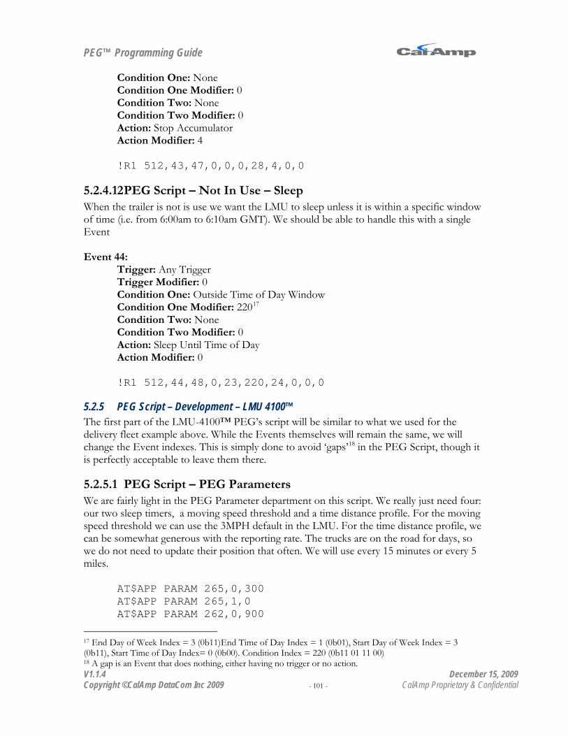
PEG™ Programming Guide
V1.1.4 December 15, 2009 Copyright ©CalAmp DataCom Inc 2009 - 101 - CalAmp Proprietary & Confidential
Condition One: None Condition One Modifier: 0 Condition Two: None Condition Two Modifier: 0 Action: Stop Accumulator Action Modifier: 4
!R1 512,43,47,0,0,0,28,4,0,0
5.2.4.12 PEG Script – Not In Use – Sleep When the trailer is not is use we want the LMU to sleep unless it is within a specific window of time (i.e. from 6:00am to 6:10am GMT). We should be able to handle this with a single Event Event 44:
Trigger: Any Trigger Trigger Modifier: 0 Condition One: Outside Time of Day Window Condition One Modifier: 22017
Condition Two: None
Condition Two Modifier: 0 Action: Sleep Until Time of Day Action Modifier: 0
!R1 512,44,48,0,23,220,24,0,0,0
5.2.5 PEG Script – Development – LMU 4100™ The first part of the LMU-4100™ PEG’s script will be similar to what we used for the delivery fleet example above. While the Events themselves will remain the same, we will change the Event indexes. This is simply done to avoid ‘gaps’18
5.2.5.1 PEG Script – PEG Parameters
in the PEG Script, though it is perfectly acceptable to leave them there.
We are fairly light in the PEG Parameter department on this script. We really just need four: our two sleep timers, a moving speed threshold and a time distance profile. For the moving speed threshold we can use the 3MPH default in the LMU. For the time distance profile, we can be somewhat generous with the reporting rate. The trucks are on the road for days, so we do not need to update their position that often. We will use every 15 minutes or every 5 miles.
AT$APP PARAM 265,0,300 AT$APP PARAM 265,1,0 AT$APP PARAM 262,0,900
17 End Day of Week Index = 3 (0b11)End Time of Day Index = 1 (0b01), Start Day of Week Index = 3 (0b11), Start Time of Day Index= 0 (0b00). Condition Index = 220 (0b11 01 11 00) 18 A gap is an Event that does nothing, either having no trigger or no action.

PEG™ Programming Guide
V1.1.4 December 15, 2009 Copyright ©CalAmp DataCom Inc 2009 - 102 - CalAmp Proprietary & Confidential
AT$APP PARAM 263,0,8045
5.2.5.2 PEG Script - Ignition On/Off Detection For the Ignition On and Off reporting we will need two PEG Events. Event 0:
Trigger: Ignition On Trigger Modifier: 0 Condition One: None Condition One Modifier: 0 Condition Two: None Condition Two Modifier: 0 Action: Send Report Action Modifier: 0
Event 1: Trigger: Ignition Off Trigger Modifier: 0 Condition One: None Condition One Modifier: 0 Condition Two: None Condition Two Modifier: 0 Action: Send Report Action Modifier: 1
Programming wise this would look as follows:
AT$APP PARAM 512,0,15,0,0,0,1,0,0,0 AT$APP PARAM 512,1,16,0,0,0,1,1,0,0
5.2.5.3 PEG Script – Sleep For the Sleep script we want to wait 5 minutes then put the unit to sleep until Ignition comes on. Event 2: This Event will start the sleep countdown sequence.
Trigger: Ignition Off Trigger Modifier: 0 Condition One: None Condition One Modifier: 0 Condition Two: None Condition Two Modifier: 0 Action: Start/Restart Timer Action Modifier: 0
Event 3: This Event will abort the sleep countdown sequence if ignition comes back on.
Trigger: Ignition On Trigger Modifier: 0 Condition One: None

PEG™ Programming Guide
V1.1.4 December 15, 2009 Copyright ©CalAmp DataCom Inc 2009 - 103 - CalAmp Proprietary & Confidential
Condition One Modifier: 0 Condition Two: None Condition Two Modifier: 0 Action: Stop Clear Timer Action Modifier: 0
Event 4: This is where we put the unit to sleep. It is a good idea to check the state of the ignition before putting the unit to sleep.
Trigger: Timer Timeout Trigger Modifier: 0 Condition One: Ignition Off Condition One Modifier: 0 Condition Two: None Condition Two Modifier: 0 Action: Sleep Timer Action Modifier: 1
Event 5: This Event isn’t strictly necessary, but it is a safe-guard against phantom wakes (for instance say some bad vehicle wiring shorts one of the other inputs on the LMU and wakes it back up).
Trigger: Power Up or Wake Up Trigger Modifier: 0 Condition One: Ignition Off Condition One Modifier: 0 Condition Two: None Condition Two Modifier: 0 Action: Start/Restart Timer Action Modifier: 0
For our AT Commands we have:
AT$APP PARAM 512,2,16,0,0,0,13,0,0,0 AT$APP PARAM 512,3,15,0,0,0,30,0,0,0 AT$APP PARAM 512,4,18,0,2,0,22,1,0,0 AT$APP PARAM 512,5,3,0,2,0,13,0,0,0
5.2.5.4 PEG Script – Time-Distance Reporting This is another fairly straight forward piece of the script. We need to star the Time-Distance profile and then kick in the Event Report whenever it expires. This should take two Events: Event 6: Start the Time Distance Profile.
Trigger: Power Up or Wake Up Trigger Modifier: 0 Condition One: None Condition One Modifier: 0 Condition Two: None Condition Two Modifier: 0

PEG™ Programming Guide
V1.1.4 December 15, 2009 Copyright ©CalAmp DataCom Inc 2009 - 104 - CalAmp Proprietary & Confidential
Action: Start Time-Distance Profile Action Modifier: 0
Event 7: Send the Event Report.
Trigger: Time-Distance Update Trigger Modifier: 0 Condition One: None Condition One Modifier: 0 Condition Two: None Condition Two Modifier: 0 Action: Send Report Action Modifier: 50
For our AT Commands we have:
AT$APP PARAM 512,6,3,0,0,0,7,0,0,0 AT$APP PARAM 512,7,17,0,0,0,1,50,0,0
5.2.5.5 PEG Script – Moving/Not Moving Reporting Unlike the delivery fleet example, we just need to report Moving and Not Moving Events since we took out the ‘At Stop’ case. Event 8: Not moving we just need to send a report
Trigger: Not Moving Trigger Modifier: 0 Condition One: None Condition One Modifier: 0 Condition Two: None Condition Two Modifier: 0 Action: Send Report Action Modifier: 105
Event 9: Handle the just Moving case
Trigger: Moving Trigger Modifier: 0 Condition One: Acc Below Condition One Modifier: 1 Condition Two: None Condition Two Modifier: 0 Action: Send Report Action Modifier: 100
AT$APP PARAM 512,8,43,0,0,0,1,105,0,0 AT$APP PARAM 512,9,42,0,25,1,1,100,0,0

PEG™ Programming Guide
V1.1.4 December 15, 2009 Copyright ©CalAmp DataCom Inc 2009 - 105 - CalAmp Proprietary & Confidential
5.2.5.6 PEG Script – Trip Odometer The trip odometer works from Ignition On to Ignition off, since we’re not actually doing anything based on this value, the script simply has to start and stop the Accumulator. Event 10: Reset Distance Counter
Trigger: Ignition Off Trigger Modifier: 0 Condition One: None Condition One Modifier: 0 Condition Two: None Condition Two Modifier: 0 Action: Stop/Clear Accumulator Action Modifier: 4
Event 11: Start Counter
Trigger: Ignition On Trigger Modifier: 0 Condition One: None Condition One Modifier: 0 Condition Two: None Condition Two Modifier: 0 Action: Start Distance Accumulation Action Modifier: 4
AT$APP PARAM 512,10,16,0,0,0,29,4,0,0 AT$APP PARAM 512,11,15,0,0,0,27,4,0,0
This is a case where the order in which Events appear in the script becomes important. In this case the Stop/Clear Event for the distance Accumulator must appear after you report the Ignition Off Event. If this Event appeared before the reporting Action, you would always get a 0 distance value.
5.2.5.7 PEG Script – Vehicle Power The LMU’s internal Analog to Digital input is connected to its power supply. So long as the LMU’s power is run directly off the vehicle battery, we should get a somewhat accurate reading of the vehicle’s power supply. Event 12: Start A/D Accumulation
Trigger: Power Up or Wake Up Trigger Modifier: 0 Condition One: None Condition One Modifier: 0 Condition Two: None Condition Two Modifier: 0

PEG™ Programming Guide
V1.1.4 December 15, 2009 Copyright ©CalAmp DataCom Inc 2009 - 106 - CalAmp Proprietary & Confidential
Action: Start A/D Accumulation Action Modifier: 0 AT$APP PARAM 512,12,3,0,0,0,47,0,0,0
5.2.5.8 PEG Script - Load Begin/End Detection The loading Event will run from a hatch open to a hatch close. We have installed a sensor that will trigger high when the hatch is open and low when the hatch is closed. This should only be valid when a trailer is connected. Event 13:
Trigger: Input High Trigger Modifier: 1 Condition One: Input Low Condition One Modifier: 3 Condition Two: None Condition Two Modifier: 0 Action: Send Report Action Modifier: 2
Event 14: Trigger: Input Low Trigger Modifier: 1 Condition One: Input Low Condition One Modifier: 3 Condition Two: None Condition Two Modifier: 0 Action: Send Report Action Modifier: 3
Programming wise this would look as follows:
AT$APP PARAM 512,13,4,1,10,3,1,2,0,0 AT$APP PARAM 512,14,5,1,10,3,1,3,0,0
5.2.5.9 PEG Script - Unload Begin/End Detection Like the load, the unloading Event will run from a hatch open to a hatch close. The same type of sensor has been installed in the unload hatch. Again, this is only valid when a trailer is connected. Event 15:
Trigger: Input High Trigger Modifier: 2 Condition One: Input Low Condition One Modifier: 3 Condition Two: None Condition Two Modifier: 0 Action: Send Report

PEG™ Programming Guide
V1.1.4 December 15, 2009 Copyright ©CalAmp DataCom Inc 2009 - 107 - CalAmp Proprietary & Confidential
Action Modifier: 4 Event 16:
Trigger: Input Low Trigger Modifier: 2 Condition One: Input Low Condition One Modifier: 3 Condition Two: None Condition Two Modifier: 0 Action: Send Report Action Modifier: 5
Programming wise this would look as follows:
AT$APP PARAM 512,15,4,2,10,3,1,4,0,0 AT$APP PARAM 512,16,5,2,10,3,1,5,0,0
5.2.5.10 PEG Script – Trailer Detection The trailer-detect circuit will behave a little differently than the two hatch Events. Namely, the trailer detect input (3) will be pulled low when the trailer is connected. Basically the input will be connected to the LMU-1000’s™ ground when a connection occurs. Event 17:
Trigger: Input Low Trigger Modifier: 3 Condition One: None Condition One Modifier: 0 Condition Two: None Condition Two Modifier: 0 Action: Send Report Action Modifier: 6
Event 18: Trigger: Input High Trigger Modifier: 3 Condition One: None Condition One Modifier: 0 Condition Two: None Condition Two Modifier: 0 Action: Send Report Action Modifier: 7
Programming wise this would look as follows:
AT$APP PARAM 512,17,5,2,0,0,1,4,0,0 AT$APP PARAM 512,18,4,2,0,0,1,5,0,0

PEG™ Programming Guide
V1.1.4 December 15, 2009 Copyright ©CalAmp DataCom Inc 2009 - 108 - CalAmp Proprietary & Confidential
5.2.5.11 PEG Script – Modem off during load and unload procedures This piece of the PEG Script will control modem power. The idea here is to turn the modem off when a load or unload starts and to turn it back on when the load/unload is complete. To accomplish this we will create a function. Our starting point, as will all functions, is to segment the PEG script. Event 100: Function Break
Trigger: Any Trigger Trigger Modifier: 0 Condition One: None Condition One Modifier: 0 Condition Two: None Condition Two Modifier: 0 Action: End Action Modifier: 0
AT$APP PARAM 512,100,48,0,0,0,53,0,0,0
We will start with turning the modem off. Event 101: Begin Load
Trigger: Any Trigger Trigger Modifier: 0 Condition One: Input High Condition One Modifier: 1 Condition Two: None Condition Two Modifier: 0 Action: Comm Off Action Modifier: 0
Event 102: Begin Unload
Trigger: Any Trigger Trigger Modifier: 0 Condition One: Input High Condition One Modifier: 2 Condition Two: None Condition Two Modifier: 0 Action: Comm Off Action Modifier: 0
AT$APP PARAM 512,101,48,0,9,1,56,0,0,0 AT$APP PARAM 512,102,48,0,9,2,56,0,0,0
Note that we’re using a comm. off Action instead of a comm. disconnect as a disconnect does not have power control over the modem.

PEG™ Programming Guide
V1.1.4 December 15, 2009 Copyright ©CalAmp DataCom Inc 2009 - 109 - CalAmp Proprietary & Confidential
Next we need to deal with the on cases: Here we need to make sure that the load processes are done. The other thing we need to do is not reset the modem unnecessarily. What we are going to do here is exit the function early if we encounter one of these Conditions. If we don’t, then we turn the modem back on and return normally. Event 103: Load is in progress:
Trigger: Any Trigger Trigger Modifier: 0 Condition One: Input High Condition One Modifier: 1 Condition Two: None Condition Two Modifier: 0 Action: Return Action Modifier: 0
Event 104: Unload is in progress
Trigger: Any Trigger Trigger Modifier: 0 Condition One: Input High Condition One Modifier: 2 Condition Two: None Condition Two Modifier: 0 Action: Return Action Modifier: 0
Event 105: Comm is already on
Trigger: Any Trigger Trigger Modifier: 0 Condition One: Comm On Condition One Modifier: 0 Condition Two: None Condition Two Modifier: 0 Action: Return Action Modifier: 0
Event 106: Turn the modem on
Trigger: Any Trigger Trigger Modifier: 0 Condition One: None Condition One Modifier: 0 Condition Two: None Condition Two Modifier: 0 Action: Comm On

PEG™ Programming Guide
V1.1.4 December 15, 2009 Copyright ©CalAmp DataCom Inc 2009 - 110 - CalAmp Proprietary & Confidential
Action Modifier: 0 Event 107: Turn the modem on
Trigger: Any Trigger Trigger Modifier: 0 Condition One: None Condition One Modifier: 0 Condition Two: None Condition Two Modifier: 0 Action: Return Action Modifier: 0
AT$APP PARAM 512,103,48,0,9,1,52,0,0,0 AT$APP PARAM 512,104,48,0,9,2,52,0,0,0 AT$APP PARAM 512,105,48,0,43,0,52,0,0,0 AT$APP PARAM 512,106,48,0,0,0,55,0,0,0 AT$APP PARAM 512,107,48,0,0,0,52,0,0,0
Note that we could have combined Events 103 and 104 together using an OR operation. In this case we have plenty of room in the PEG script, so we didn’t bother. To complete our function we need to make a call into it. This will occur on any High Low transition from either Input 1 or 2. Event 19:
Trigger: Input Transition Trigger Modifier: 1 Condition One: None Condition One Modifier: 0 Condition Two: None Condition Two Modifier: 0 Action: Call Action Modifier: 101
Event 20: Trigger: Input Transition Trigger Modifier: 2 Condition One: None Condition One Modifier: 0 Condition Two: None Condition Two Modifier: 0 Action: Call Action Modifier: 101
Programming wise this would look as follows:
AT$APP PARAM 512,19,31,1,0,0,51,101,0,0 AT$APP PARAM 512,20,31,2,0,0,51,101,0,0

PEG™ Programming Guide
V1.1.4 December 15, 2009 Copyright ©CalAmp DataCom Inc 2009 - 111 - CalAmp Proprietary & Confidential
5.2.5.12 PEG Script –Unsafe load and unload warning This part of the script assumes that output 0 has been connected to the horn of the vehicle (see the LMU Users Guide for details on this). When the output is set, we honk the horn, when it is cleared the honk stops. Our warnings should occur when the vehicle’s ignition is still on, and either a load or unload hatch is open. The honk should stop when ignition goes off. We will start with turning the honk off since it’s a little easier. Event 21:
Trigger: Ignition Off Trigger Modifier: 0 Condition One: None Condition One Modifier: 0 Condition Two: None Condition Two Modifier: 0 Action: Clear Output Action Modifier: 0
AT$APP PARAM 512,21,16,0,0,0,9,0,0,0
Event 22:
Trigger: Input High Trigger Modifier: 1 Condition One: Ignition On Condition One Modifier: 0 Condition Two: None Condition Two Modifier: 0 Action: Set Output Action Modifier: 0
Event 23: Trigger: Input High Trigger Modifier: 2 Condition One: Ignition On Condition One Modifier: 0 Condition Two: None Condition Two Modifier: 0 Action: Set Output Action Modifier: 0
AT$APP PARAM 512,22,4,1,1,0,8,0,0,0 AT$APP PARAM 512,23,4,2,1,0,8,0,0,0
Lastly we need to send in a report whenever a load/unload warning occurs. Event 24:

PEG™ Programming Guide
V1.1.4 December 15, 2009 Copyright ©CalAmp DataCom Inc 2009 - 112 - CalAmp Proprietary & Confidential
Trigger: Input High Trigger Modifier: 1 Condition One: Ignition On Condition One Modifier: 0 Condition Two: None Condition Two Modifier: 0 Action: Send Report Action Modifier: 91
Event 25: Trigger: Input High Trigger Modifier: 2 Condition One: Ignition On Condition One Modifier: 0 Condition Two: None Condition Two Modifier: 0 Action: Send Report Action Modifier: 91
AT$APP PARAM 512,24,4,1,1,0,1,91,0,0 AT$APP PARAM 512,25,4,2,1,0,1,91,0,0
5.2.5.13 PEG Script –Crossing State Boundaries Our final piece of the PEG script will perform two functions, first it will detect when the vehicle enters or leaves a state. Second, it will count the distance travelled in each state. Here we are going to assume three geo-zones have been setup to define the state boundaries (see the LMU Users Guide for information on how to program Geo-Zones). We are making two assumptions on how this feature should operate. The first assumption is that distance will be measured from the entry into one state to the entry into the next state. Our second assumption is that state boundaries do not overlap. That is, it is impossible to be in more than one state at a time. The one place where this breaks down is a cold boot. The LMU will report that it has left state 0 when it first obtains GPS. So long as the Geo-Zone/State ID values are non-zero, we should be able to hide this case from the end user in the Remote Application. The Remote Application should only read the distance value on an Exit Event (i.e. Event Code 201). Event 26:
Trigger: Any Geo-Zone Entry Trigger Modifier: 0 Condition One: None Condition One Modifier: 0 Condition Two: None Condition Two Modifier: 0 Action: Send Report Action Modifier: 201

PEG™ Programming Guide
V1.1.4 December 15, 2009 Copyright ©CalAmp DataCom Inc 2009 - 113 - CalAmp Proprietary & Confidential
Event 27: Trigger: Any Geo-Zone Entry Trigger Modifier: 0 Condition One: None Condition One Modifier: 0 Condition Two: None Condition Two Modifier: 0 Action: Start Geo-Zone Accumulation Action Modifier: 6
Event 28: Trigger: Any Geo-Zone Entry Trigger Modifier: 0 Condition One: None Condition One Modifier: 0 Condition Two: None Condition Two Modifier: 0 Action: Send Report Action Modifier: 200
Event 29: Trigger: Any Geo-Zone Entry Trigger Modifier: 0 Condition One: None Condition One Modifier: 0 Condition Two: None Condition Two Modifier: 0 Action: Clear Accumulator Action Modifier: 5
Event 30: Trigger: Any Geo-Zone Entry Trigger Modifier: 0 Condition One: None Condition One Modifier: 0 Condition Two: None Condition Two Modifier: 0 Action: Start Distance Accumulator Action Modifier: 5
AT$APP PARAM 512,26,55,0,0,0,1,201,0,0 AT$APP PARAM 512,27,55,0,0,0,67,6,0,0 AT$APP PARAM 512,28,55,0,0,0,1,200,0,0 AT$APP PARAM 512,29,55,0,0,0,19,5,0,0 AT$APP PARAM 512,30,55,0,0,0,27,5,0,0
PEG™ Programming Guide
V1.1.4 December 15, 2009 Copyright ©CalAmp DataCom Inc 2009 - 114 - CalAmp Proprietary & Confidential
5.3
5.3.1 Project Overview
PEG Programming – Taxi System
For our final project we are going to look at the Hagensville Cab Company. The Hagensville Cab Company is a small organization with approximately 20 vehicles and has been losing business to larger fleets. The owners are hoping that by adding GPS they can improve the efficiency of their existing fleet as well as add a couple of services their competitors do not offer. They are looking for the following:
• Real-Time updates from each vehicle • Distance travelled, drive times and idle times for maintenance purposes • Messaging between the cab and the back end system (i.e. dispatch) • Real-Time Credit Card processing (they’ve had a few problems with fraudulent credit
cards) • Dispatch notification of when a cab becomes available
For their backend piece they are looking for two applications, one to be used by their dispatcher to route cabs to the nearest vehicle, the other application will be part of their website, allowing users to locate the nearest cab and view arrival estimates for cab reservations.
5.3.2 Project Proposal
5.3.2.1 LMU Requirements As with the previous two projects, we will start with the choice of wireless technology. In this case, the decision will be made based on coverage. All three operators do have coverage within Hagensville and its airport, only the CDMA operator has sufficient coverage in the surrounding suburbs. In the LMU will we handle the following features:
• Real-Time updates, likely based on an aggressive Time-Distance profile. To limit the amount of queuing (and hence any latencies), these reports will be sent un-acknowledged.
• Distance Travelled – Drive times will start counting distance from Ignition On to Ignition Off. Both ignition Events will be recorded, though the distance data is only valid in the Ignition Off Report
• Drive Time – Drive times extend from Moving to Not Moving. Again, we will report both Events, but the data is only meaningful in the Not Moving report.
• Idle Time – Idle time is measured from Not Moving to Moving or Not Moving to Ignition Off. Idle time will be cumulative between Ignition Offs and hence only be reported then.

PEG™ Programming Guide
V1.1.4 December 15, 2009 Copyright ©CalAmp DataCom Inc 2009 - 115 - CalAmp Proprietary & Confidential
5.3.2.2 Local Application Requirements The Local Application will be in two parts, an MDT to handle messaging between the driver and the dispatcher and a credit card reader to handle payment processing. We are planning to take advantage of the LMU’s User Messaging feature to handle both. This means that we will need the ioPOD with Aux Port. Please note that the set-up of the LMU to support this is described in the LMU Users Guide. For the MDT we will need the following messages:
• Cab Available (Driver –> Dispatch) • Request Pickup, includes address (Dispatch -> Driver) • Cab in use (Driver -> Dispatch) • Cancel Pickup (Dispatch -> Driver) • At pickup (Driver -> Dispatch)
For the driver messages, each will be assigned to a particular button on the MDT. The incoming messages will be shown on the four line display. On the credit card processing side we are expecting the card reader to encrypt the credit card data before sending it to the LMU. The LMU, in turn sends the message to the back end (again using an unacknowledged service). The back end will decrypt the data and forward it to the credit card processing agent. Once an authorization has been received, notification is sent back to the LMU and credit card reader to allow the transaction and print a receipt.
5.3.2.3 Remote Application Requirements To support the customer’s needs the Remote Application will need to do the following:
• Send and Receive Messages to/from the MDT. • Display all MDT messages to the Dispatch application. • Display all vehicle locations in the dispatch application including availability status • Display only available cabs in the website application • Display ETA to pickup data for ‘reserved’ cabs in website application • Receive and decrypt credit card data • Process credit card data with an appropriate clearing house • Return authorization notification to the credit card reader connected to the LMU
5.3.3 PEG Script – Planning The PEG script for this application is fairly simple and should look a lot like the script we used for the delivery vehicle application. In fact, we could simply copy the delivery vehicle script and call it complete. We are, however, going to make some modifications. The primary one will be in relation to the time-distance profile. We want the profile to be aggressive if we’re looking for real-time tracking. We will therefore use 60s or 500m. Programming wise, this would be

PEG™ Programming Guide
V1.1.4 December 15, 2009 Copyright ©CalAmp DataCom Inc 2009 - 116 - CalAmp Proprietary & Confidential
AT$APP PARAM 262,0,60 AT$APP PARAM 263,0,500
The second change will be in how this data is reported. We are going to use unacknowledged reporting. This will enable two things:
• Unacknowledged message bypass the Log which means we can eliminate delays due to Log delivery.
• We do get some airtime savings since there is no acknowledgement message. Given the volume of messages we’ll be creating, this could have a significant impact on the budget.
Keep in mind the reports that we are really interested in (Ignition and Moving Events) will be Logged. This is to make sure the distance traveled, idle time and travel time data are never lost.
5.3.4 PEG Script - Development Development wise this is going to be the least interesting script thus far. We are simply going to copy the existing script we created for the delivery fleet and make the modification to the time distance profile. The interesting part of this application is on the LMU setup side with the MDT messaging.
5.3.4.1 PEG Script – Time-Distance Reporting Event 6: Start the Time Distance Profile. This remains untouched from the delivery fleet profile.
Trigger: Power Up or Wake Up Trigger Modifier: 0 Condition One: None Condition One Modifier: 0 Condition Two: None Condition Two Modifier: 0 Action: Start Time-Distance Profile Action Modifier: 0
Event 7: Send the Event Report.
Trigger: Time-Distance Update Trigger Modifier: 0 Condition One: None Condition One Modifier: 0 Condition Two: None Condition Two Modifier: 0 Action: Send Unacknowledged Report Action Modifier: 50
For our AT Commands we have:
AT$APP PARAM 512,6,3,0,0,0,7,0,0,0

PEG™ Programming Guide
V1.1.4 December 15, 2009 Copyright ©CalAmp DataCom Inc 2009 - 117 - CalAmp Proprietary & Confidential
AT$APP PARAM 512,7,17,0,0,0,44,50,0,0

PEG™ Programming Guide
V1.1.4 December 15, 2009 Copyright ©CalAmp DataCom Inc 2009 - 118 - CalAmp Proprietary & Confidential
For the purposes of PEG, there are effectively 4 different platforms, the LMU-4100, the LMU-2500, the LMU-1000/1500 and the 8-Bit products (MTU-100, LMU-900, LMU-1100 and LMU-1200)
Appendix A – PEG Triggers
Trigger Name
Trigger C
ode
Description Trigger Modifier Definition
8-Bit
LMU
- 1000
LMU
-2500
LMU
-4100
Not Active 0 The Event is not active
None 1.2d 1.4b X 8.1b
Power Up 1 The LMU has been powered up
None 1.2d 1.4b X 8.1b
Wake Up 2 The LMU has woken from sleep
None 1.2d 1.4b X 8.1b
Power Up or Wake Up
3 The LMU has either been powered on or has woke from sleep
None 1.2d 1.4b X 8.1b
Input High 4 The input specified in the Trigger Modifier field has transitioned from low to high.
The input to monitor: 0 = Ignition 1 = Input 1 2 = Input 2 3 = Input 3 4 = Input 4 5 = Input 5 6 = Input 6 7 = Input 7
1.2d 1.4b X 8.1b
Input Low 5 The input specified in the Trigger Modifier field has transitioned from high to low.
The input to monitor: 0 = Ignition 1 = Input 1 2 = Input 2 3 = Input 3 4 = Input 4 5 = Input 5 6 = Input 6 7 = Input 7
1.2d 1.4b X 8.1b
Input Equate 6 The value specified by the Trigger Modifier matches the current states of all monitored inputs.
Each bit represents an input state. If the input is high, the Bit is set, if the input is low, the bit is cleared:
bit 0 = Ignition bit 1 = Input 1 bit 2 = Input 2 bit 3 = Input 3 bit 4 = Input 4 bit 5 = Input 5 bit 6 = Input 6 bit 7 = Input 7
1.4b X 8.1b
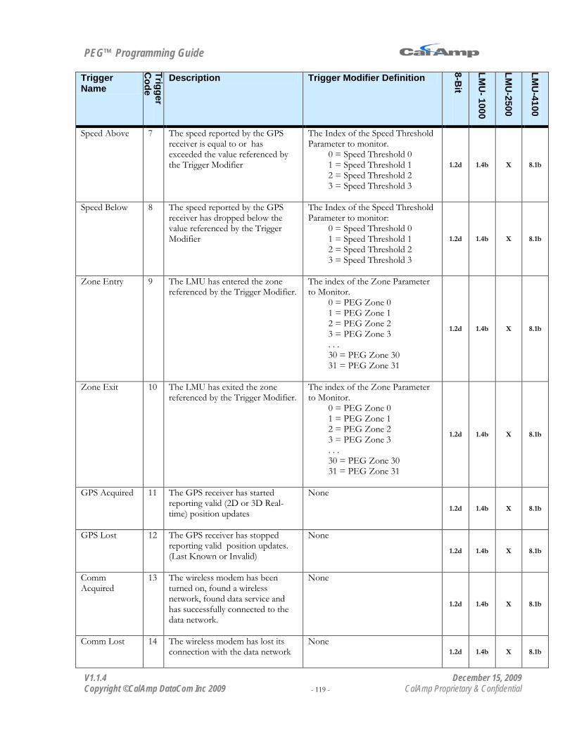
PEG™ Programming Guide
V1.1.4 December 15, 2009 Copyright ©CalAmp DataCom Inc 2009 - 119 - CalAmp Proprietary & Confidential
Trigger Name
Trigger C
ode
Description Trigger Modifier Definition
8-Bit
LMU
- 1000
LMU
-2500
LMU
-4100
Speed Above 7 The speed reported by the GPS receiver is equal to or has exceeded the value referenced by the Trigger Modifier
The Index of the Speed Threshold Parameter to monitor.
0 = Speed Threshold 0 1 = Speed Threshold 1 2 = Speed Threshold 2 3 = Speed Threshold 3
1.2d 1.4b X 8.1b
Speed Below 8 The speed reported by the GPS receiver has dropped below the value referenced by the Trigger Modifier
The Index of the Speed Threshold Parameter to monitor:
0 = Speed Threshold 0 1 = Speed Threshold 1 2 = Speed Threshold 2 3 = Speed Threshold 3
1.2d 1.4b X 8.1b
Zone Entry 9 The LMU has entered the zone referenced by the Trigger Modifier.
The index of the Zone Parameter to Monitor.
0 = PEG Zone 0 1 = PEG Zone 1 2 = PEG Zone 2 3 = PEG Zone 3 . . . 30 = PEG Zone 30 31 = PEG Zone 31
1.2d 1.4b X 8.1b
Zone Exit 10 The LMU has exited the zone referenced by the Trigger Modifier.
The index of the Zone Parameter to Monitor.
0 = PEG Zone 0 1 = PEG Zone 1 2 = PEG Zone 2 3 = PEG Zone 3 . . . 30 = PEG Zone 30 31 = PEG Zone 31
1.2d 1.4b X 8.1b
GPS Acquired 11 The GPS receiver has started reporting valid (2D or 3D Real-time) position updates
None
1.2d 1.4b X 8.1b
GPS Lost 12 The GPS receiver has stopped reporting valid position updates. (Last Known or Invalid)
None
1.2d 1.4b X 8.1b
Comm Acquired
13 The wireless modem has been turned on, found a wireless network, found data service and has successfully connected to the data network.
None
1.2d 1.4b X 8.1b
Comm Lost 14 The wireless modem has lost its connection with the data network
None 1.2d 1.4b X 8.1b

PEG™ Programming Guide
V1.1.4 December 15, 2009 Copyright ©CalAmp DataCom Inc 2009 - 120 - CalAmp Proprietary & Confidential
Trigger Name
Trigger C
ode
Description Trigger Modifier Definition
8-Bit
LMU
- 1000
LMU
-2500
LMU
-4100
Ignition On 15 The LMU’s Ignition input (input 0) has transitioned from low to high.
None 1.2d 1.4b X 8.1b
Ignition Off 16 The LMU’s ignition input (input 0) has transitioned from high to low
None 1.2d 1.4b X 8.1b
Time-Distance Update
17 One of the Time-Distance settings (Time, Distance, Heading) has been exceeded in the active Time-Distance profile
None
1.2d 1.4b X 8.1b
Timer Timeout 18 The timer value referenced by the Trigger Modifier has reached 0.
The index of the Timer value to monitor:
0 = Timer 0 1 = Timer 1 2 = Timer 2 3 = Timer 3 . . . 14 = Timer 14 15 = Timer 15
1.2d 1.4b X 8.1b
Accumulator Above
19 The Accumulator value referenced by the Trigger Modifier is equal to or has exceeded is threshold value
The index of the Accumulator to monitor:
0 = Accumulator 0 1 = Accumulator 0 2 = Accumulator 0 3 = Accumulator 0 . . . 14 = Accumulator 0 15 = Accumulator 0
1.2d 1.4b X 8.1b
Time of Day 20 The current time of the LMU has passed the time referenced in the Trigger Modifier. This Trigger will fire on a wake-up if the time of day has passed while the LMU was sleeping.
The Time of Day to monitor. 0 = Time of Day 0 1 = Time of Day 1 2 = Time of Day 2 3 = Time of Day 3
1.2d 1.4b X 8.1b
Log Buffer Full 21 The LMU’s Log space has been filled to more than 80%
None 1.2d 1.4b X 8.1b
Host Data 22 Not Active
None 1.1a 8.1b
Long Send Failure
23 This Trigger will fire when the LMU’s Log Send Sequence has expired
None
1.2d 1.4b X 8.1b
Wake Up on Input
24 The L:MU has woken from sleep based on an input transition
None 1.2d 1.4b X 8.1b
Wake Up on Timer
25 The LMU has woken from sleep based on a timer timeout.
None 1.2d 1.4b X 8.1b

PEG™ Programming Guide
V1.1.4 December 15, 2009 Copyright ©CalAmp DataCom Inc 2009 - 121 - CalAmp Proprietary & Confidential
Trigger Name
Trigger C
ode
Description Trigger Modifier Definition
8-Bit
LMU
- 1000
LMU
-2500
LMU
-4100
Message Sent 26 A User Message with the type specified in the Trigger Modifier has been sent to the Inbound address
The User Message Type. 0 - 255
1.1a 8.1b
Message Acknowledged
27 A User Message with the type specified in the Trigger Modifier has been sent to the Inbound address and been acknowledged
The User Message Type. 0 - 255
1.1a 8.1b
Message Send Failure
28 A User Message with the type specified in the Trigger Modifier has been sent to the Inbound address but did not receive an acknowledge
The User Message Type. 0 - 255
1.1a 8.1b
Log Report Success
29 The LMU has successfully reported all of its Logged data.
None 1.2d 1.4b X 8.1b
Comm Shutdown
30 The wireless modem has been powered off
None 1.2d 1.4b X 8.1b
Input Transition
31 The input specified in the Trigger Modifier field has transitioned from high to low or from low to high
The input to monitor: 0 = Ignition 1 = Input 1 2 = Input 2 3 = Input 3 4 = Input 4 5 = Input 5 6 = Input 6 7 = Input 7
1.2d 1.4b X 8.1b
Any Zone Entry
32 The LMU has entered one of the defined PEG Zones
None 1.2d 1.4b X 8.1b
Any Zone Exit 33 The LMU has exited one of the defined PEG Zones
None 1.2d 1.4b X 8.1b
Time Elapsed 34 The time component of the active Time-Distance Profile has been exceeded
None
1.2d 1.4b X 8.1b
Distance Traveled
35 The distance component of the active Time-Distance Profile has been exceeded
None
1.2d 1.4b X 8.1b
Log Active 36 The LMU has been forced to Log an Inbound message. This Event only fires once until the Log is successfully emptied or cleared.
None
1.2d 1.4b X 8.1b

PEG™ Programming Guide
V1.1.4 December 15, 2009 Copyright ©CalAmp DataCom Inc 2009 - 122 - CalAmp Proprietary & Confidential
Trigger Name
Trigger C
ode
Description Trigger Modifier Definition
8-Bit
LMU
- 1000
LMU
-2500
LMU
-4100
Message Received
37 The LMU has received a User Message matching the type specified in the Trigger Modifier
The User Message Type. 0 - 255
1.1a 8.1b
Any Message Received
38 The LMU has received a User Message
1.1a 8.1b
Environment Change
39 Any of the states in the Environment Mask referenced by the Trigger Modifier have changed.
The Environment Mask to monitor:
0 = Environment 0 1 = Environment 1 2 = Environment 2 3 = Environment 3 4 = Environment 4 5 = Environment 5 6 = Environment 6 7 = Environment 7
X 1.4b X 8.1b
Heading Change
40 The heading component of the active Time-Distance Profile has been exceeded
None
1.2d 1.4b X 8.1b
Special 41 Not Active
None 8.1b
Moving 42 The LMU’s speed is equal to or has exceeded the Moving Speed Threshold Parameter.
None
1.2d 1.4b X 8.1b
Not Moving 43 The LMU’s speed has dropped below the Moving Speed Threshold Parameter.
None
1.2d 1.4b X 8.1b
A/D Above 44 The internal A/D (A/D0) has exceeded the value referenced by the Trigger Modifier.
The index of the A/D Threshold to use as applied to ADC 0:
0 = ADC Threshold 0 1 = ADC Threshold 1 2 = ADC Threshold 2 3 = ADC Threshold 3
1.4b X 8.1b
A/D Below 45 The internal A/D (A/D0) has dropped below the value referenced by the Trigger Modifier.
The index of the A/D Threshold to use as applied to ADC 0:
0 = ADC Threshold 0 1 = ADC Threshold 1 2 = ADC Threshold 2 3 = ADC Threshold 3
1.4b X 8.1b
Comm Connected
46 The LMU has successfully established a data connection with the wireless network (i.e. it has obtained an IP address)
None
1.2d 1.4b X 8.1b
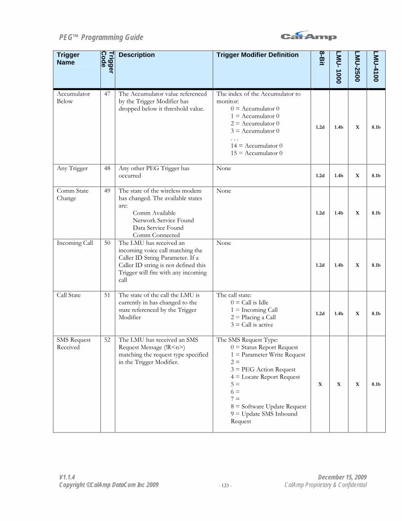
PEG™ Programming Guide
V1.1.4 December 15, 2009 Copyright ©CalAmp DataCom Inc 2009 - 123 - CalAmp Proprietary & Confidential
Trigger Name
Trigger C
ode
Description Trigger Modifier Definition
8-Bit
LMU
- 1000
LMU
-2500
LMU
-4100
Accumulator Below
47 The Accumulator value referenced by the Trigger Modifier has dropped below it threshold value.
The index of the Accumulator to monitor:
0 = Accumulator 0 1 = Accumulator 0 2 = Accumulator 0 3 = Accumulator 0 . . . 14 = Accumulator 0 15 = Accumulator 0
1.2d 1.4b X 8.1b
Any Trigger 48 Any other PEG Trigger has occurred
None 1.2d 1.4b X 8.1b
Comm State Change
49 The state of the wireless modem has changed. The available states are:
Comm Available Network Service Found Data Service Found Comm Connected
None
1.2d 1.4b X 8.1b
Incoming Call 50 The LMU has received an incoming voice call matching the Caller ID String Parameter. If a Caller ID string is not defined this Trigger will fire with any incoming call
None
1.2d 1.4b X 8.1b
Call State 51 The state of the call the LMU is currently in has changed to the state referenced by the Trigger Modifier
The call state: 0 = Call is Idle 1 = Incoming Call 2 = Placing a Call 3 = Call is active
1.2d 1.4b X 8.1b
SMS Request Received
52 The LMU has received an SMS Request Message (!R<n>) matching the request type specified in the Trigger Modifier.
The SMS Request Type: 0 = Status Report Request 1 = Parameter Write Request 2 = 3 = PEG Action Request 4 = Locate Report Request 5 = 6 = 7 = 8 = Software Update Request 9 = Update SMS Inbound Request
X X X 8.1b

PEG™ Programming Guide
V1.1.4 December 15, 2009 Copyright ©CalAmp DataCom Inc 2009 - 124 - CalAmp Proprietary & Confidential
Trigger Name
Trigger C
ode
Description Trigger Modifier Definition
8-Bit
LMU
- 1000
LMU
-2500
LMU
-4100
Geo-Zone Entry
53 The LMU has entered the Geo-Zone (Point or Polygon) referenced by the Trigger Modifier.
The Geo-Zone ID 0 = Geo-Zone 0 1 = Geo-Zone 1 . . . 254 = Geo-Zone 254 255 = Geo-Zone 255
NOTE: This Trigger will fire for any Geo-Zone whose ID matches the Trigger Modifier regardless of Super Group assignment
8.1b
Geo-Zone Exit 54 The LMU has left the Geo-Zone (Point or Polygon) referenced by the Trigger Modifier.
The Geo-Zone ID 0 = Geo-Zone 0 1 = Geo-Zone 1 . . . 254 = Geo-Zone 254 255 = Geo-Zone 255
NOTE: This Trigger will fire for any Geo-Zone whose ID matches the Trigger Modifier regardless of Super Group assignment
8.1b
Any Geo-Zone Entry
55 The LMU has entered any of the defined Geo-Zones (point or polygon)
None
8.1b
Any Geo-Zone Exit
56 The LMU has left any of the defined Geo-Zones (point or polygon)
None
8.1b
Null SMS Message Received
57 The LMU has received an SMS message which has an empty body.
None 1.2d 1.4b X 8.1b
Network ID Change
58 The Carrier ID value has changed. That is, the LMU has moved to a new network.
None 1.2d 1.4b X 8.2c
1-Bit-Bus ID Read
59 The 1Bit-Bus has just read an iButton ID value
None X X
Update Begin 60 An Over-The Air Update has begun
The type of update that has been requested:
0 = Configuration Update 1 = Firmware Update 2-255 = Reserved
1.1b 1.4b 1.0f 8.3c
Update End 61 An Over-The Air Update has completed
The type of update that has been requested:
0 = Configuration Update 1 = Firmware Update 2-255 = Reserved
1.1b 1.4b 1.0f 8.3c
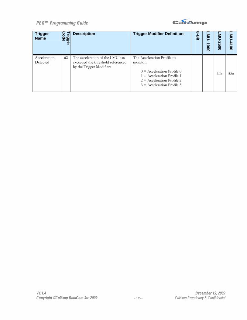
PEG™ Programming Guide
V1.1.4 December 15, 2009 Copyright ©CalAmp DataCom Inc 2009 - 125 - CalAmp Proprietary & Confidential
Trigger Name
Trigger C
ode
Description Trigger Modifier Definition
8-Bit
LMU
- 1000
LMU
-2500
LMU
-4100
Acceleration Detected
62 The acceleration of the LMU has exceeded the threshold referenced by the Trigger Modifiers
The Acceleration Profile to monitor:
0 = Acceleration Profile 0 1 = Acceleration Profile 1 2 = Acceleration Profile 2 3 = Acceleration Profile 3
1.1k 8.4a

PEG™ Programming Guide
V1.1.4 December 15, 2009 Copyright ©CalAmp DataCom Inc 2009 - 126 - CalAmp Proprietary & Confidential
Appendix B – PEG Conditions Condition Name
Condition
Code
Description Condition Modifier Definition
8-Bit
LMU
-1000
LMU
-2500
LMU
-4100
None 0 The Event has no Condition
None 1.2d 1.4b X 8.1b
Ignition On 1 The LMU’s Ignition line (input 0) is in the high state.
None 1.2d 1.4b X 8.1b
Ignition Off 2 The LMU’s Ignition line (input 0) is in the low state.
None 1.2d 1.4b X 8.1b
Moving 3 The LMU’s current speed is equal to or above the value in the Moving Speed Threshold Parameter.
None
1.2d 1.4b X 8.1b
Not Moving 4 The LMU’s current speed is below the value in the Moving Speed Threshold Parameter.
None
1.2d 1.4b X 8.1b
Comm Available
5 The LMU’s wireless modem is registered to the network and is able to send data.
None
1.2d 1.4b X 8.1b
Comm Not Available
6 The LMU’s wireless modem is not registered to the network.
None
1.2d 1.4b X 8.1b
GPS Acquired 7 The LMU’s GPS receiver is currently producing a valid GPS position (2D or 3D real-time fix)
None
1.2d 1.4b X 8.1b
GPS Not Acquired
8 The LMU’s GPS receiver is not producing a valid GPS position (Invalid Time, Invalid Fix, Last Known Fix)
None
1.2d 1.4b X 8.1b
Input High 9 The input referenced by the Condition Modifier is in the high state.
The input to monitor: 0 = Ignition 1 = Input 1 2 = Input 2 3 = Input 3 4 = Input 4 5 = Input 5 6 = Input 6 7 = Input 7
1.2d 1.4b X 8.1b

PEG™ Programming Guide
V1.1.4 December 15, 2009 Copyright ©CalAmp DataCom Inc 2009 - 127 - CalAmp Proprietary & Confidential
Condition Name
Condition
Code
Description Condition Modifier Definition
8-Bit
LMU
-1000
LMU
-2500
LMU
-4100
Input Low 10 The input referenced by the Condition Modifier is in the low state.
The input to monitor: 0 = Ignition 1 = Input 1 2 = Input 2 3 = Input 3 4 = Input 4 5 = Input 5 6 = Input 6 7 = Input 7
1.2d 1.4b X 8.1b
Timer Active 11 The timer referenced by the Condition Modifier is currently running (i.e. counting down)
The index of the Timer value to monitor:
0 = Timer 0 1 = Timer 1 2 = Timer 2 3 = Timer 3 . . . 14 = Timer 14 15 = Timer 15
1.2d 1.4b X 8.1b
Timer Inactive 12 The timer referenced by the Condition Modifier is not running (i.e. timer has stopped)
The index of the Timer value to monitor:
0 = Timer 0 1 = Timer 1 2 = Timer 2 3 = Timer 3 . . . 14 = Timer 14 15 = Timer 15
1.2d 1.4b X 8.1b
Time-Distance Active
13 The Time-Distance profile referenced by the Condition Modifier is the active profile.
The index of the Time-Distance Profile to monitor:
0 = Time-Distance 0 1 = Time-Distance 1 2 = Time-Distance 2 3 = Time-Distance 3
1.2d 1.4b X 8.1b
Time-Distance Inactive
14 The Time-Distance profile referenced by the Condition Modifier is not the active profile.
The index of the Time-Distance Profile to monitor:
0 = Time-Distance 0 1 = Time-Distance 1 2 = Time-Distance 2 3 = Time-Distance 3
1.2d 1.4b X 8.1b
Day of Week 15 The current day of week, based on the LMU’s local time settings, matches one of the days selected in the Day of Week Parameter referenced by the Condition Modifier.
The index of the Timer value to monitor:
0 = Day Of Week 0 1 = Day Of Week 1 2 = Day Of Week 2 3 = Day Of Week 3
1.2d 1.4b X 8.1b

PEG™ Programming Guide
V1.1.4 December 15, 2009 Copyright ©CalAmp DataCom Inc 2009 - 128 - CalAmp Proprietary & Confidential
Condition Name
Condition
Code
Description Condition Modifier Definition
8-Bit
LMU
-1000
LMU
-2500
LMU
-4100
Flag Set 16 The PEG Flag referenced by the Condition Modifier is currently set.
The PEG Flag to monitor: 0 = PEG Flag 0 1 = PEG Flag 1 2 = PEG Flag 2 3 = PEG Flag 3 . . . 14 = PEG Flag 14 15 = PEG Flag 15
1.2d 1.4b X 8.1b
Flag Cleared 17 The PEG Flag referenced by the Condition Modifier is currently cleared.
The PEG Flag to monitor: 0 = PEG Flag 0 1 = PEG Flag 1 2 = PEG Flag 2 3 = PEG Flag 3 . . . 14 = PEG Flag 14 15 = PEG Flag 15
1.2d 1.4b X 8.1b
Log Active 18 The LMU’s is actively Logging data, either in Store and Forward or Batch mode.
None
1.2d 1.4b X 8.1b
Comm and GPS Available
19 The LMU’s wireless modem is registered to the network and is able to send data and its GPS receiver is currently producing a valid GPS position (2D or 3D real-time fix)
None
1.2d 1.4b X 8.1b
Environment 20 Any one of the Conditions in the Environment Parameter referenced by the Condition Modifier is true.
The Environment Mask to monitor:
0 = Environment 0 1 = Environment 1 2 = Environment 2 3 = Environment 3 4 = Environment 4 5 = Environment 5 6 = Environment 6 7 = Environment 7
1.4b X 8.1b

PEG™ Programming Guide
V1.1.4 December 15, 2009 Copyright ©CalAmp DataCom Inc 2009 - 129 - CalAmp Proprietary & Confidential
Condition Name
Condition
Code
Description Condition Modifier Definition
8-Bit
LMU
-1000
LMU
-2500
LMU
-4100
Environment Equate
21 The environment described by the Condition Modifier is true. For this Condition, environments are paired where the first environment is the mask (which items to monitor) and the second is the states of the items (high/Log, inside/out/etc…)
The Environment to monitor (Mask/State)
0 = Environment 0/4 1 = Environment 1/5 2 = Environment 2/6 3 = Environment 3/7
1.4b X 8.1b
Inside Time of Day Window
22 The current day and time reported by the GPS receiver and based on the LMU’s local time settings are within the window defined by the Condition Modifier
This field is separated into 4 parts. The fields must be combined to make a single value ranging from 0 -255 bit 0& bit 1 =
Starting Time Of Day index (0-3)
bit 2 & bit 3 = Starting Day Of Week index (0-3)
bit 4 & bit 5 = End Time Of Day index (0-3)
bit 6 & bit 7 = End Day Of Week index (0-3)
1.2d 1.4b X 8.1b
Outside Time of Day Window
23 The current day and time reported by the GPS receiver and based on the LMU’s local time settings are outside the window defined by the Condition Modifier
This field is separated into 4 parts. The fields must be combined to make a single value ranging from 0 -255 bit 0& bit 1 =
Starting Time Of Day index (0-3)
bit 2 & bit 3 = Starting Day Of Week index (0-3)
bit 4 & bit 5 = End Time Of Day index (0-3)
bit 6 & bit 7 = End Day Of Week index (0-3)
1.2d 1.4b X 8.1b

PEG™ Programming Guide
V1.1.4 December 15, 2009 Copyright ©CalAmp DataCom Inc 2009 - 130 - CalAmp Proprietary & Confidential
Condition Name
Condition
Code
Description Condition Modifier Definition
8-Bit
LMU
-1000
LMU
-2500
LMU
-4100
Accumulator Above
24 The Accumulator value referenced by the Condition Modifier is equal to or above its threshold value.
The index of the Accumulator to monitor:
0 = Accumulator 0 1 = Accumulator 0 2 = Accumulator 0 3 = Accumulator 0 . . . 14 = Accumulator 0 15 = Accumulator 0
1.2d 1.4b X 8.1b
Accumulator Below
25 The Accumulator value referenced by the Condition Modifier is below its threshold value.
The index of the Accumulator to monitor:
0 = Accumulator 0 1 = Accumulator 0 2 = Accumulator 0 3 = Accumulator 0 . . . 14 = Accumulator 0 15 = Accumulator 0
1.2d 1.4b X 8.1b
Comm State 26 The state of the wireless modem matches the state defined in the Condition Modifier
This value is split into two fields, a mask and state. bit 7 -4 = Mask
Set = Monitor state Cleared = Do not monitor state.
bit 7 = Monitor Data Service Connected
bit 6 = Monitor Data Service Available
bit 5 = Monitor Network Service Acquired
bit 4 = Monitor Network Service available
bit 3 – 0 = States Set = State is true Cleared = State is not true
bit 3 = Data Service Connected
bit 2 = Data Service Available
bit 1 = Network Service Acquired
bit 0 = Network Available
1.2d 1.4b X 8.1b

PEG™ Programming Guide
V1.1.4 December 15, 2009 Copyright ©CalAmp DataCom Inc 2009 - 131 - CalAmp Proprietary & Confidential
Condition Name
Condition
Code
Description Condition Modifier Definition
8-Bit
LMU
-1000
LMU
-2500
LMU
-4100
Log Inactive 27 The LMU has not Logged any data since last emptying or clearing its Log
None
1.2d 1.4b X 8.1b
Input Compare 28 The inputs on the LMU match the state defined by the Condition Modifier
The state of the LMU’s input line with each bit representing an input. The input is high if the bit is set and low if the bit is cleared.
bit 0 = Ignition bit 1 = Input 1 bit 2 = Input 2 bit 3 = Input 3 bit 4 = Input 4 bit 5 = Input 5 bit 6 = Input 6 bit 7 = Input 7
1.2d 1.4b X 8.1b
PEG Flag Compare
29 The current states of the LMU’s lower 8 PEG Flags (0-7) match the states defined in the Condition Modifier.
The state of the lower 8 PEG Flags with each bit representing a flag. The flag is set if the bit is set and cleared if the bit is cleared.
bit 0 = PEG Flag 0 bit 1 = PEG Flag 1 bit 2 = PEG Flag 2 bit 3 = PEG Flag 3 bit 4 = PEG Flag 4 bit 5 = PEG Flag 5 bit 6 = PEG Flag 6 bit 7 = PEG Flag 7
1.2d 1.4b X 8.1b
Time Valid 30 The status of the current time value being produced by the LMU’s GPS receiver.
The state of the time produced by the LMU’s GPS receiver.
0 = The Time is Invalid 1 = The Time is Valid 2-255 = Unknown state
1.2d 1.4b X 8.1b
Comm Select 31 Determines which comm. settings are currently being used by the LMU.
This field is separated into two parts, the Comm Index and the Inbound Index. bit 7 -4 =
Comm Index (0-1)
bit 3 – 0 = Inbound Index (0-3)
1.4b X 8.1b
Log Full 32 The LMU’s Log is currently more than 80% full.
None 1.2d 1.4b X 8.1b

PEG™ Programming Guide
V1.1.4 December 15, 2009 Copyright ©CalAmp DataCom Inc 2009 - 132 - CalAmp Proprietary & Confidential
Condition Name
Condition
Code
Description Condition Modifier Definition
8-Bit
LMU
-1000
LMU
-2500
LMU
-4100
User Flag 33 The User Flag Parameter matches the value specified in the Condition Modifier
This field is separated into two parts, a mask and state: bit 7 -4 = Mask
Set = Monitor state Cleared = Do not monitor state.
bit 7 = Monitor User Flag 3
bit 6 = Monitor User Flag 2
bit 5 = Monitor User Flag 1
bit 4 = Monitor User Flag 0
bit 3 – 0 = States Set = User Flag is set Cleared = User Flag is cleared
bit 3 = User Flag 3
bit 2 = User Flag 2
bit 1 = User Flag 1
bit 0 = User Flag 0
1.2d 1.4b X 8.1b
Call Status 34 The current state and call type of the wireless modem.
This field is separated into three parts, a Mask, the Call Type and the Call State Bits 4-7 = Mask Bit 2 & 3 = Call Type
0 = voice 1 = data 2 = position 3 = other
Bit 0 & 1 = Call State 0 = idle 1 = incoming 2 = calling 3 = active
1.2d 1.4b X 8.1b
Speed Above 35 The Index of the Speed Threshold Parameter to monitor:
0 = Speed Threshold 0 1 = Speed Threshold 1 2 = Speed Threshold 2 3 = Speed Threshold 3
1.2d 1.4b X 8.1b

PEG™ Programming Guide
V1.1.4 December 15, 2009 Copyright ©CalAmp DataCom Inc 2009 - 133 - CalAmp Proprietary & Confidential
Condition Name
Condition
Code
Description Condition Modifier Definition
8-Bit
LMU
-1000
LMU
-2500
LMU
-4100
Supergroup 36 This Condition applies only to Geo-Zones. If the Geo-Zone referenced in the Trigger (Geo Zone Entry/Exit, Any Geo-Zone Entry/Exit) belongs to the Super Group referenced in the Condition Modifier, this Condition is true.
The Super Group ID to be monitored.
0 = Super Group 0 1 = Super Group 1 2 = Super Group 2 3 = Super Group 3
8.1b
Roaming 37 This Condition is true if the wireless modem indicates it is roaming.
None 1.2d 1.4b X 8.1b
PEG Enables 38 This Condition is true if the PEG Enables Parameter bit referenced by the Condition Modifier is set.
The bit of the PEG Enables Parameter to monitor:
0 = PEG Enable 0 1 = PEG Enable 1 2 = PEG Enable 2 3 = PEG Enable 3 . . . 30 = PEG Enable 30 31 = PEG Enable 31
1.2d 1.4b X 8.1b
Boot Reason 39 This condition is true if the Boot Reason matches what is indicated by the Condition Modifier
The Boot Reason: 0 = Cold Boot / Power Up 1 = Factory Boot 2 = OTA Download Complete 3 = Radio Power Up 4 = Wake Due to I/O activity 5 = Wake due to Timer 6 = Wake due to SMS message 7 = Wake due to App Restart Action or AT Command
1.2d 1.4b X 8.2c
Zone State 40 This condition is true if the Zone indicated in the Condition Modifier matches the state defined in the Condition Modifier.
This field is separated into two parts, the Zone to monitor and the desired State. Bit 7 = Zone State
Set = LMU is Inside Zone Cleared = LMU is outside Zone
Bit 0 - 6 = The PEG Zone to Monitor
0 = PEG Zone 0 1 =PEG Zone 1 … 31 = PEG Zone 31
1.2d 1.4b X 8.2f

PEG™ Programming Guide
V1.1.4 December 15, 2009 Copyright ©CalAmp DataCom Inc 2009 - 134 - CalAmp Proprietary & Confidential
Condition Name
Condition
Code
Description Condition Modifier Definition
8-Bit
LMU
-1000
LMU
-2500
LMU
-4100
PEG State Compare
41 This condition is true if the PEG State Variable is equal to the value of the Condition Modifier
This field should contain the desired PEG State Variable 1.2d 1.4b X 8.2g
Accumulator Equal
42 This condition is true if the accumulator defined in the Condition Modifier is equal to its threshold value.
The index of the Accumulator to monitor:
0 = Accumulator 0 1 = Accumulator 0 2 = Accumulator 0 3 = Accumulator 0 . . . 14 = Accumulator 0 15 = Accumulator 0
1.2d 1.4b X 8.2h
Comm On 43 This condition is true if the LMU’s radio is powered on
None 1.2d 1.4b X 8.2h
GPS On 44 This condition is true if the LMU’s GPS receiver is powered on
None 1.2d 1.4b X 8.2h
Zone Enabled 45 This condition is true if the PEG Zone indicated by the Condition Modifier is enabled
The PEG Zone to Monitor 0 = PEG Zone 0 1 =PEG Zone 1 … 31 = PEG Zone 31
1.2d 1.4b X 8.2h
One Bit Bus Detection
46 This condition is true if a device is detected on the LMU’s 1-Bit Bus
None X 8.2h
GPS Fix Quality
47 This condition is true if the current fix from the GPS receiver is better than the threshold defined by the Condition Modifier.
The GPS Fix Quality Threshold: - 0 = Threshold Off - 1 = Sat Count >= 4 and
HDOP <= 2.0 - 2 = Sat Count >= 5 and
HDOP <= 2.0 - 3 = Sat Count >= 5 and
HDOP <= 1.5 - 4 = Sat Count >= 6 and
HDOP <= 1.5 - 5 = Sat Count >= 7 and
HDOP <= 1.5 - 6 = Sat Count >= 8 and
HDOP <= 1.5 - 7 = Sat Count >= 8 and
HDOP <= 1.2 - 8 = Use threshold
defined by S-Register 174
1.2k 1.1a 8.4a

PEG™ Programming Guide
V1.1.4 December 15, 2009 Copyright ©CalAmp DataCom Inc 2009 - 135 - CalAmp Proprietary & Confidential
Condition Name
Condition
Code
Description Condition Modifier Definition
8-Bit
LMU
-1000
LMU
-2500
LMU
-4100
AND/OR bit 6 (+64)
This bit determines how Condition one and Condition two are used. They may be combined by means of a Logical AND or a Logical OR. In a Logical AND operation both Conditions must be true for the Event to occur, in a Logical OR operation, either or both of the Conditions can be true for the Event to occur.
bit 6 Set = (Condition 1) OR (Condition 2) Cleared = (Condition 1) AND (Condition 2)
1.2d 1.4b X 8.1b
NOT bit 7 (+128)
A Logical NOT operation may be applied to a Conditions via the most-significant bit of the Condition’s Index Value. (For example, Not Ignition On uses an Index Value of 129).
bit 7: Set = NOT(Condition) Cleared = (Condition)
1.2d 1.4b X 8.1b
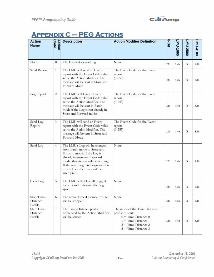
PEG™ Programming Guide
V1.1.4 December 15, 2009 Copyright ©CalAmp DataCom Inc 2009 - 136 - CalAmp Proprietary & Confidential
Appendix C – PEG Actions Action Name
Action
Code
Description Action Modifier Definition 8-B
it
LMU
-1000
LMU
-2500
LMU
-4100
None 0 The Event does nothing
None 1.2d 1.4b X 8.1b
Send Report 1 The LMU will send an Event report with the Event Code value set to the Action Modifier. The message will be sent in Store and Forward Mode
The Event Code for the Event report (0-255)
1.2d 1.4b X 8.1b
Log Report 2 The LMU will Log an Event report with the Event Code value set to the Action Modifier. The message will be sent in Batch mode if the Log is not already in Store and Forward mode.
The Event Code for the Event report (0-255)
1.2d 1.4b X 8.1b
Send-Log Report
3 The LMU will send an Event report with the Event Code value set to the Action Modifier. The message will be sent in Store and Forward Mode
The Event Code for the Event report (0-255) 1.2d 1.4b X 8.1b
Send Log 4 The LMU’s Log will be changed from Batch mode to Store and Forward mode. If the Log is already in Store and Forward mode, this Action will do nothing. If the send Log retry sequence has expired, another retry will be attempted.
None
1.2d 1.4b X 8.1b
Clear Log 5 The LMU will delete all Logged records and re-format the Log space.
None
1.2d 1.4b X 8.1b
Stop Time-Distance Profile
6 The active Time-Distance profile will be stopped.
None 1.2d 1.4b X 8.1b
Start Time-Distance Profile
7 The Time-Distance profile referenced by the Action Modifier will be started.
The index of the Time-Distance profile to start:
0 = Time-Distance 0 1 = Time-Distance 1 2 = Time-Distance 2 3 = Time-Distance 3
1.2d 1.4b X 8.1b

PEG™ Programming Guide
V1.1.4 December 15, 2009 Copyright ©CalAmp DataCom Inc 2009 - 137 - CalAmp Proprietary & Confidential
Action Name
Action
Code
Description Action Modifier Definition
8-Bit
LMU
-1000
LMU
-2500
LMU
-4100
Set Output 8 The output referenced by the Action Modifier will be set.
The output to set: 6 = Output 6 5 = Output 5 4 = Output 4 3 = Output 3 2 = Output 2 1 = Output 1 0 = Output 0
1.2d 1.4b X 8.1b
Clear Output 9 The output referenced by the Action Modifier will be cleared.
The output to clear: 6 = Output 6 5 = Output 5 4 = Output 4 3 = Output 3 2 = Output 2 1 = Output 1 0 = Output 0
1.2d 1.4b X 8.1b
One-shot output
10 The output referenced by the Action Modifier will be set for 1s then be cleared.
The output to set: 6 = Output 6 5 = Output 5 4 = Output 4 3 = Output 3 2 = Output 2 1 = Output 1 0 = Output 0
1.2d 1.4b X 8.1b
Blink Output at 1Hz Rate
11 The output referenced by the Action Modifier will be set and cleared every 1s.
The output to blink: 6 = Output 6 5 = Output 5 4 = Output 4 3 = Output 3 2 = Output 2 1 = Output 1 0 = Output 0
1.2d 1.4b X 8.1b
Blink Output at 4 Hz Rate
12 The output referenced by the Action Modifier will be set and cleared every 0.25s.
The output to blink: 6 = Output 6 5 = Output 5 4 = Output 4 3 = Output 3 2 = Output 2 1 = Output 1 0 = Output 0
1.2d X 8.1b

PEG™ Programming Guide
V1.1.4 December 15, 2009 Copyright ©CalAmp DataCom Inc 2009 - 138 - CalAmp Proprietary & Confidential
Action Name
Action
Code
Description Action Modifier Definition
8-Bit
LMU
-1000
LMU
-2500
LMU
-4100
Start/Restart Timer
13 The timer referenced by the Action Modifier will be started from its threshold value. When the Timer reaches 0 it will be restarted.
The timer to start: 0 = Timer 0 1 = Timer 1 2 = Timer 2 3 = Timer 3 . . . 14 = Timer 14 15 = Timer 15
1.2d 1.4b X 8.1b
Stop/Pause Timer
14 The timer specified by the Action Modifier will be stopped at its current value.
The timer to stop: 0 = Timer 0 1 = Timer 1 2 = Timer 2 3 = Timer 3 . . . 14 = Timer 14 15 = Timer 15
1.2d 1.4b X 8.1b
Start/Resume Timer
15 The timer referenced by the Action Modifier will be started from its current value. If the timer reaches 0, the timer will be restarted.
The timer to start: 0 = Timer 0 1 = Timer 1 2 = Timer 2 3 = Timer 3 . . . 14 = Timer 14 15 = Timer 15
1.2d 1.4b X 8.1b
Clear Timer 16 The timer referenced by the Action Modifier will be reset to its threshold value.
The timer to clear: 0 = Timer 0 1 = Timer 1 2 = Timer 2 3 = Timer 3 . . . 14 = Timer 14 15 = Timer 15
1.2d 1.4b X 8.1b
One-shot Timer
17 The timer referenced by the Action Modifier will be started from its threshold value. When the timer reaches 0 it will be stopped.
The timer to start: 0 = Timer 0 1 = Timer 1 2 = Timer 2 3 = Timer 3 . . . 14 = Timer 14 15 = Timer 15
1.2d 1.4b X 8.1b

PEG™ Programming Guide
V1.1.4 December 15, 2009 Copyright ©CalAmp DataCom Inc 2009 - 139 - CalAmp Proprietary & Confidential
Action Name
Action
Code
Description Action Modifier Definition
8-Bit
LMU
-1000
LMU
-2500
LMU
-4100
Increment Accumulator
18 The Accumulator referenced by the Action Modifier will be incremented by 1.
The Accumulator to increment: 0 = Accumulator 0 1 = Accumulator 1 2 = Accumulator 2 3 = Accumulator 3 . . . 14 = Accumulator 14 15 = Accumulator 15
1.2d 1.4b X 8.1b
Clear Accumulator
19 The value of the Accumulator referenced by the Action Modifier will be cleared to 0.
The Accumulator to increment: 0 = Accumulator 0 1 = Accumulator 1 2 = Accumulator 2 3 = Accumulator 3 . . . 14 = Accumulator 14 15 = Accumulator 15
1.2d 1.4b X 8.1b
Power Up GPS
20 The GPS receiver will be powered on. IF the receiver is already on, it will be reset
None
1.2d 1.4b X 8.1b
Power Down GPS
21 The GPS receiver will be powered off. If the receiver is already off, it will remain off
None
1.2d 1.4b X 8.1b
Sleep (Timer) 22 The LMU will go to sleep for the duration specified by the timer referenced by the Action Modifier. If the timer’s value is 0, the LMU will go to sleep indefinitely.
The timer to use for sleep duration:
0 = Timer 0 1 = Timer 1 2 = Timer 2 3 = Timer 3 . . . 14 = Timer 14 15 = Timer 15
1.2d 1.4b X 8.1b
Sleep Enabled 23 Enables the LMU to go to sleep. Enable/Disable 0 = Disable Sleep 1 = Enable Sleep 2 – 255 = Reserved
X 8.1b
Sleep Until Time of Day
24 The LMU will go to sleep until the time referenced by the Action Modifier
The Time of Day value to sleep to: 0 = Time of Day 0 1 = Time of Day 1 2 = Time of Day 2 3 = Time of Day 3
1.2d 1.4b X 8.1b

PEG™ Programming Guide
V1.1.4 December 15, 2009 Copyright ©CalAmp DataCom Inc 2009 - 140 - CalAmp Proprietary & Confidential
Action Name
Action
Code
Description Action Modifier Definition
8-Bit
LMU
-1000
LMU
-2500
LMU
-4100
Output Word 25 The LMU will set and clear its outputs to match the states indicated by the Action Modifier
The state of each output. Each output is assigned to a specific bit. If the bit is set, the output will be set, If the bit is cleared, the output will be cleared.
bit 6 = output 6 bit 5 = output 5 bit 4 = output 4 bit 3 = output 3 bit 2 = output 2 bit 1 = output 1 bit 0 = output 0
1.2d X X 8.1b
Start Time Accumulator
26 The Accumulator referenced by the Action Modifier will start counting seconds.
The Accumulator to start: 0 = Accumulator 0 1 = Accumulator 1 2 = Accumulator 2 3 = Accumulator 3 . . . 14 = Accumulator 14 15 = Accumulator 15
1.2d 1.4b X 8.1b
Start Distance Accumulator
27 The Accumulator referenced by the Action Modifier will start counting meters traveled.
The Accumulator to start: 0 = Accumulator 0 1 = Accumulator 1 2 = Accumulator 2 3 = Accumulator 3 . . . 14 = Accumulator 14 15 = Accumulator 15
1.2d 1.4b X 8.1b
Stop Accumulator
28 The Accumulator referenced by the Action Modifier will be stopped at its current value.
The Accumulator to stop: 0 = Accumulator 0 1 = Accumulator 1 2 = Accumulator 2 3 = Accumulator 3 . . . 14 = Accumulator 14 15 = Accumulator 15
1.2d 1.4b X 8.1b
Stop and Clear Accumulator
29 The Accumulator referenced by the Action Modifier will be stopped and its value will be set to 0.
The Accumulator to stop: 0 = Accumulator 0 1 = Accumulator 1 2 = Accumulator 2 3 = Accumulator 3 . . . 14 = Accumulator 14 15 = Accumulator 15
1.2d 1.4b X 8.1b
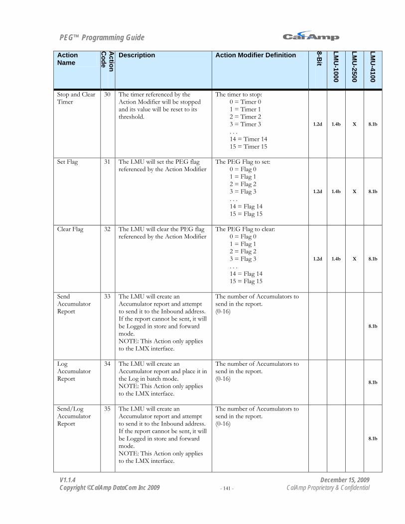
PEG™ Programming Guide
V1.1.4 December 15, 2009 Copyright ©CalAmp DataCom Inc 2009 - 141 - CalAmp Proprietary & Confidential
Action Name
Action
Code
Description Action Modifier Definition
8-Bit
LMU
-1000
LMU
-2500
LMU
-4100
Stop and Clear Timer
30 The timer referenced by the Action Modifier will be stopped and its value will be reset to its threshold.
The timer to stop: 0 = Timer 0 1 = Timer 1 2 = Timer 2 3 = Timer 3 . . . 14 = Timer 14 15 = Timer 15
1.2d 1.4b X 8.1b
Set Flag 31 The LMU will set the PEG flag referenced by the Action Modifier
The PEG Flag to set: 0 = Flag 0 1 = Flag 1 2 = Flag 2 3 = Flag 3 . . . 14 = Flag 14 15 = Flag 15
1.2d 1.4b X 8.1b
Clear Flag 32 The LMU will clear the PEG flag referenced by the Action Modifier
The PEG Flag to clear: 0 = Flag 0 1 = Flag 1 2 = Flag 2 3 = Flag 3 . . . 14 = Flag 14 15 = Flag 15
1.2d 1.4b X 8.1b
Send Accumulator Report
33 The LMU will create an Accumulator report and attempt to send it to the Inbound address. If the report cannot be sent, it will be Logged in store and forward mode. NOTE: This Action only applies to the LMX interface.
The number of Accumulators to send in the report. (0-16)
8.1b
Log Accumulator Report
34 The LMU will create an Accumulator report and place it in the Log in batch mode. NOTE: This Action only applies to the LMX interface.
The number of Accumulators to send in the report. (0-16) 8.1b
Send/Log Accumulator Report
35 The LMU will create an Accumulator report and attempt to send it to the Inbound address. If the report cannot be sent, it will be Logged in store and forward mode. NOTE: This Action only applies to the LMX interface.
The number of Accumulators to send in the report. (0-16)
8.1b
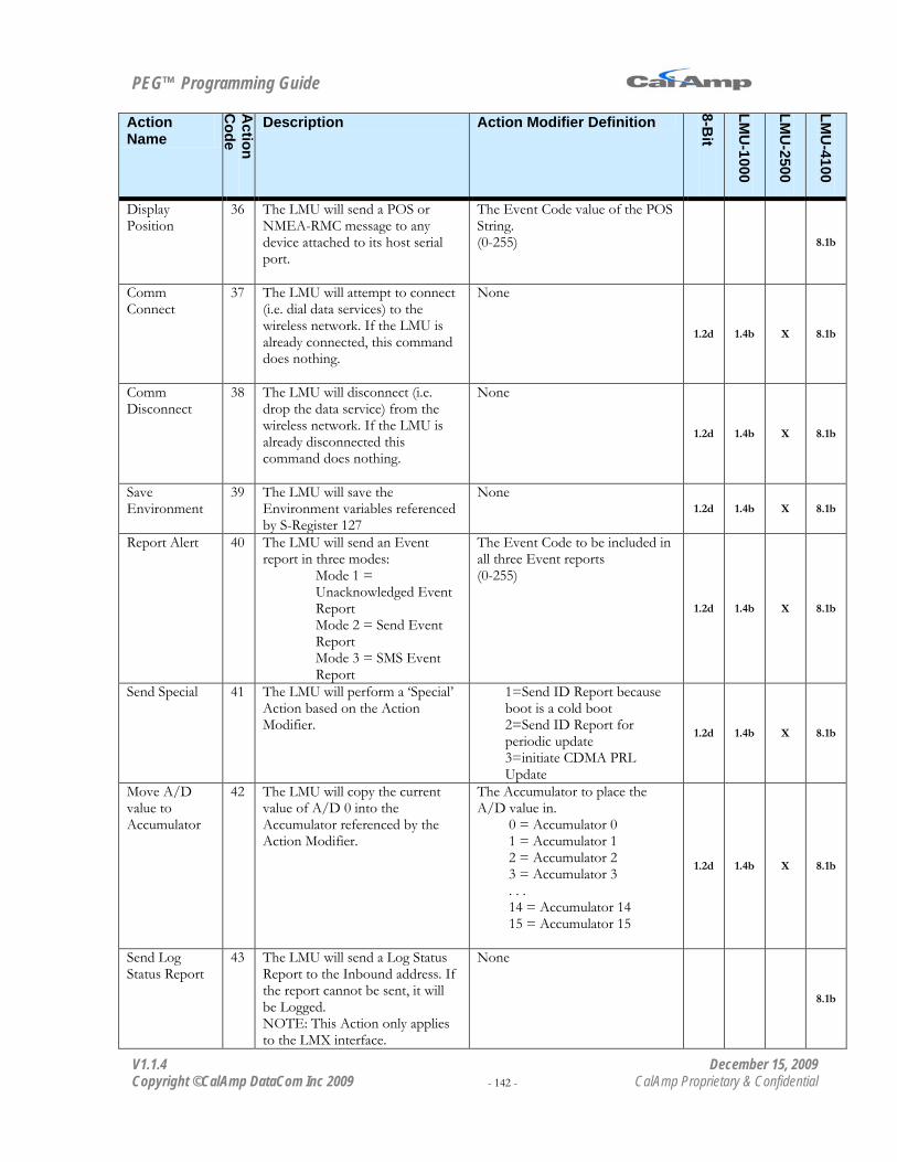
PEG™ Programming Guide
V1.1.4 December 15, 2009 Copyright ©CalAmp DataCom Inc 2009 - 142 - CalAmp Proprietary & Confidential
Action Name
Action
Code
Description Action Modifier Definition
8-Bit
LMU
-1000
LMU
-2500
LMU
-4100
Display Position
36 The LMU will send a POS or NMEA-RMC message to any device attached to its host serial port.
The Event Code value of the POS String. (0-255) 8.1b
Comm Connect
37 The LMU will attempt to connect (i.e. dial data services) to the wireless network. If the LMU is already connected, this command does nothing.
None
1.2d 1.4b X 8.1b
Comm Disconnect
38 The LMU will disconnect (i.e. drop the data service) from the wireless network. If the LMU is already disconnected this command does nothing.
None
1.2d 1.4b X 8.1b
Save Environment
39 The LMU will save the Environment variables referenced by S-Register 127
None 1.2d 1.4b X 8.1b
Report Alert 40 The LMU will send an Event report in three modes:
Mode 1 = Unacknowledged Event Report Mode 2 = Send Event Report Mode 3 = SMS Event Report
The Event Code to be included in all three Event reports (0-255)
1.2d 1.4b X 8.1b
Send Special 41 The LMU will perform a ‘Special’ Action based on the Action Modifier.
1=Send ID Report because boot is a cold boot 2=Send ID Report for periodic update 3=initiate CDMA PRL Update
1.2d 1.4b X 8.1b
Move A/D value to Accumulator
42 The LMU will copy the current value of A/D 0 into the Accumulator referenced by the Action Modifier.
The Accumulator to place the A/D value in.
0 = Accumulator 0 1 = Accumulator 1 2 = Accumulator 2 3 = Accumulator 3 . . . 14 = Accumulator 14 15 = Accumulator 15
1.2d 1.4b X 8.1b
Send Log Status Report
43 The LMU will send a Log Status Report to the Inbound address. If the report cannot be sent, it will be Logged. NOTE: This Action only applies to the LMX interface.
None
8.1b

PEG™ Programming Guide
V1.1.4 December 15, 2009 Copyright ©CalAmp DataCom Inc 2009 - 143 - CalAmp Proprietary & Confidential
Action Name
Action
Code
Description Action Modifier Definition
8-Bit
LMU
-1000
LMU
-2500
LMU
-4100
Send Unacknowledged Event Report
44 The LMU will send an Event report using the Unacknowledged service. The report will not be Logged.
The Event Code to include in the Event Report. (0-255) 1.2d 1.4b X 8.1b
Send TAIP Report
45 The LMU will send a message using the TAIP settings. TAIP messages are never Logged.
The Event Code to include in the TAIP message if the Event Code option is enabled.
X 8.1b
Start Max Speed Accumulator
46 The LMU will sample its maximum speed value into the Accumulator referenced by the Action Modifier. The speed will be in cm/s
The Accumulator to place the speed value in.
0 = Accumulator 0 1 = Accumulator 1 2 = Accumulator 2 3 = Accumulator 3 . . . 14 = Accumulator 14 15 = Accumulator 15
1.2d 1.4b X 8.1b
Start A/D Accumulator
47 The LMU will sample the A/D specified by the Action Modifier into the Accumulator specified by the Action Modifier.
This field is separated into two parts, the A/D to read and the Accumulator to place the value in. Bit 15 – Bit 8 = A/D
4 = A/D 4 3 = A/D 3 2 = A/D 2 1 = A/D 1 0 = A/D 0 (internal)
Bit 7 – Bit 0 = Accumulator 15 = Accumulator 15 14 = Accumulator 14 . . . 1 = Accumulator 1 0 = Accumulator 0
(e.g. Put A/D 3 in Accum 15 (3F=63))
1.2d 1.4b X 8.1b
Decrement Accumulator
48 The Accumulator referenced by the Action Modifier will be decremented by 1. If the value is at 0, it will remain at 0.
The Accumulator decrement. 0 = Accumulator 0 1 = Accumulator 1 2 = Accumulator 2 3 = Accumulator 3 . . . 14 = Accumulator 14 15 = Accumulator 15
1.2d 1.4b X 8.1b
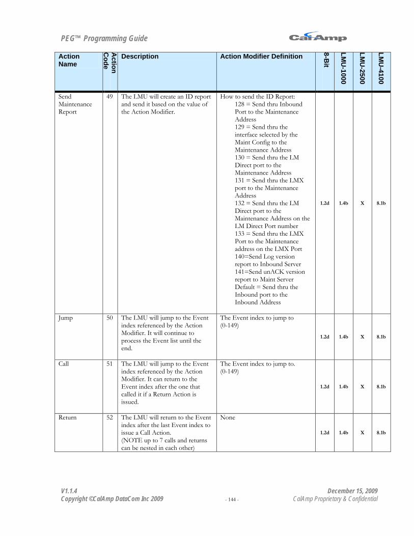
PEG™ Programming Guide
V1.1.4 December 15, 2009 Copyright ©CalAmp DataCom Inc 2009 - 144 - CalAmp Proprietary & Confidential
Action Name
Action
Code
Description Action Modifier Definition
8-Bit
LMU
-1000
LMU
-2500
LMU
-4100
Send Maintenance Report
49 The LMU will create an ID report and send it based on the value of the Action Modifier.
How to send the ID Report: 128 = Send thru Inbound Port to the Maintenance Address 129 = Send thru the interface selected by the Maint Config to the Maintenance Address 130 = Send thru the LM Direct port to the Maintenance Address 131 = Send thru the LMX port to the Maintenance Address 132 = Send thru the LM Direct port to the Maintenance Address on the LM Direct Port number 133 = Send thru the LMX Port to the Maintenance address on the LMX Port 140=Send Log version report to Inbound Server 141=Send unACK version report to Maint Server Default = Send thru the Inbound port to the Inbound Address
1.2d 1.4b X 8.1b
Jump 50 The LMU will jump to the Event index referenced by the Action Modifier. It will continue to process the Event list until the end.
The Event index to jump to (0-149)
1.2d 1.4b X 8.1b
Call 51 The LMU will jump to the Event index referenced by the Action Modifier. It can return to the Event index after the one that called it if a Return Action is issued.
The Event index to jump to. (0-149)
1.2d 1.4b X 8.1b
Return 52 The LMU will return to the Event index after the last Event index to issue a Call Action. (NOTE up to 7 calls and returns can be nested in each other)
None
1.2d 1.4b X 8.1b
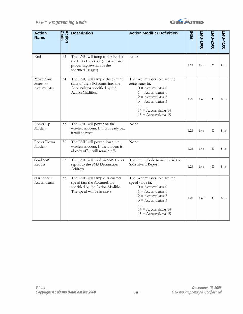
PEG™ Programming Guide
V1.1.4 December 15, 2009 Copyright ©CalAmp DataCom Inc 2009 - 145 - CalAmp Proprietary & Confidential
Action Name
Action
Code
Description Action Modifier Definition
8-Bit
LMU
-1000
LMU
-2500
LMU
-4100
End 53 The LMU will jump to the End of the PEG Event list (i.e. it will stop processing Events for the specified Trigger)
None
1.2d 1.4b X 8.1b
Move Zone States to Accumulator
54 The LMU will sample the current state of the PEG zones into the Accumulator specified by the Action Modifier.
The Accumulator to place the zone states in.
0 = Accumulator 0 1 = Accumulator 1 2 = Accumulator 2 3 = Accumulator 3 . . . 14 = Accumulator 14 15 = Accumulator 15
1.2d 1.4b X 8.1b
Power Up Modem
55 The LMU will power on the wireless modem. If it is already on, it will be reset.
None
1.2d 1.4b X 8.1b
Power Down Modem
56 The LMU will power down the wireless modem. If the modem is already off, it will remain off.
None
1.2d 1.4b X 8.1b
Send SMS Report
57 The LMU will send an SMS Event report to the SMS Destination Address
The Event Code to include in the SMS Event Report. 1.2d 1.4b X 8.1b
Start Speed Accumulator
58 The LMU will sample its current speed into the Accumulator specified by the Action Modifier. The speed will be in cm/s
The Accumulator to place the speed value in.
0 = Accumulator 0 1 = Accumulator 1 2 = Accumulator 2 3 = Accumulator 3 . . . 14 = Accumulator 14 15 = Accumulator 15
1.2d 1.4b X 8.1b

PEG™ Programming Guide
V1.1.4 December 15, 2009 Copyright ©CalAmp DataCom Inc 2009 - 146 - CalAmp Proprietary & Confidential
Action Name
Action
Code
Description Action Modifier Definition
8-Bit
LMU
-1000
LMU
-2500
LMU
-4100
Start Max A/D Value Accumulator
59 The LMU will sample the maximum value of the A/D specified by the Action Modifier into the Accumulator specified by the Action Modifier.
This field is separated into two parts, the A/D to read and the Accumulator to place the value in. Bit 15 – Bit 8 = A/D
4 = A/D 4 3 = A/D 3 2 = A/D 2 1 = A/D 1 0 = A/D 0 (internal)
Bit 7 – Bit 0 = Accumulator 15 = Accumulator 15 14 = Accumulator 14 . . . 1 = Accumulator 1 0 = Accumulator 0
1.2d 1.4b X 8.1b
Select Comm Profile
60 The LMU will change its comm settings to the profile specified by the Action Modifier
This field is separated into two parts, the Comm Settings (dial string, username and password) and the Inbound address. Bit 15 – Bit 8 = Comm Settings
1 = Dial String 1, Username 1 and Password 1 0 = Dial String 0, Username 0 and Password 0
Bit 7 – Bit 0 = Inbound Address 3 = Inbound Address 3 2 = Inbound Address 2 1 = Inbound Address 1 and Inbound URL 1 0 = Inbound Address 0 and Inbound URL 0
1.2d 1.4b X 8.1b

PEG™ Programming Guide
V1.1.4 December 15, 2009 Copyright ©CalAmp DataCom Inc 2009 - 147 - CalAmp Proprietary & Confidential
Action Name
Action
Code
Description Action Modifier Definition
8-Bit
LMU
-1000
LMU
-2500
LMU
-4100
Send Long Text Message
61 The LMU will send the long text message specified by the Action Modifier to path specified by the Action Modifier
This field is split into 4 fields. bit 7 = Carriage Return
Set = append CR to message Clear = No CR
bit 6 = Line Feed Set = append LF to message Clear = No LF
bit 5 – 4 = Path 3 = Send to SMS Destination Address 2 = Send to Aux Serial Port 1 = Send to Modem Serial Port 0 = Send to Host Serial Port
bit 3 – 0 7 = Long Text Message 7 6 = Long Text Message 6 . . . 1 = Long Text Message 1 0 = Long Text Message 0
X 8.1b
Send Short Text Message
62 The LMU will send the short text message specified by the Action Modifier to path specified by the Action Modifier
This field is split into 4 fields. bit 7 = Carriage Return
Set = append CR to message Clear = No CR
bit 6 = Line Feed Set = append LF to message Clear = No LF
bit 5 – 4 = Path 3 = Send to SMS Destination Address 2 = Send to Aux Serial Port 1 = Send to Modem Serial Port 0 = Send to Host Serial Port
bit 3 – 0 15 = Short Text Message 15 14 = Short Text Message 14 . . . 1 = Short Text Message 1 0 = Short Text Message 0
X 8.1b

PEG™ Programming Guide
V1.1.4 December 15, 2009 Copyright ©CalAmp DataCom Inc 2009 - 148 - CalAmp Proprietary & Confidential
Action Name
Action
Code
Description Action Modifier Definition
8-Bit
LMU
-1000
LMU
-2500
LMU
-4100
Start Position Accuracy Accumulator
63 The LMU will start sampling the position accuracy estimate (in meters) into the Accumulator specified by the Action Modifier.
The Accumulator to sample the position accuracy estimate in.
0 = Accumulator 0 1 = Accumulator 1 2 = Accumulator 2 3 = Accumulator 3 . . . 14 = Accumulator 14 15 = Accumulator 15
1.2d 1.4b X 8.1b
Move PEG Flag states to Accumulator
64 The LMU will copy the current state of all 16 PEG Flags into the Accumulator specified by the Action Modifier
The Accumulator to place the PEG Flag states in.
0 = Accumulator 0 1 = Accumulator 1 2 = Accumulator 2 3 = Accumulator 3 . . . 14 = Accumulator 14 15 = Accumulator 15
1.2d 1.4b X 8.1b
Set Application ID
65 Sets the Application ID value specified by the Accumulator
The application ID/ (0-255)
Send Text Status Message
66 The LMU will send a Text Status message to the path specified by the Action Modifier.
This field is split into 4 fields. bit 7 = Carriage Return
Set = append CR to message Clear = No CR
bit 6 = Line Feed Set = append LF to message Clear = No LF
bit 5 – 4 = Path 3 = Send to SMS Destination Address 2 = Send to Aux Serial Port 1 = Send to Modem Serial Port 0 = Send to Host Serial Port
bit 3 – 0 Text Status Type 0 - 15
X 8.1b

PEG™ Programming Guide
V1.1.4 December 15, 2009 Copyright ©CalAmp DataCom Inc 2009 - 149 - CalAmp Proprietary & Confidential
Action Name
Action
Code
Description Action Modifier Definition
8-Bit
LMU
-1000
LMU
-2500
LMU
-4100
Start Geo-Zone Accumulation
67 The LMU will sample the Geo-Zone ID of the last Geo-Zone boundary that was crossed into the Accumulator specified by the Action Modifier. The Geo-Zone will be mapped as follows:
Bits 0-7 = Geo-Zone ID Bits 8-15 = Super-group ID Bits 16-23 = Geo-Zone Type (1=PtZone,2=Polygon,) Bits 24-31 = Entry/Exit (1=Entry, 0=Exit)
The Accumulator to sample the Geo-Zone in.
0 = Accumulator 0 1 = Accumulator 1 2 = Accumulator 2 3 = Accumulator 3 . . . 14 = Accumulator 14 15 = Accumulator 15
8.1b
Set Text Attributes
68 The LMU will set the Text Attributes for the Send Long and Send Short message Actions based on the value of the Action Modifier.
This field is split into 4 fields. If the bit is set, the value is appended to the Text Message
Bit 3 = Local(1) vs GMT (0) timestamp Bit 2 = Add Date Bit 1 = Add Time (See Bit 3 for GMT Offset) Bit 0 = Mobile ID
X 8.1b
Start I/O State Accumulator
69 The LMU will sample the states of the inputs and outputs into the Accumulator specified by the Action Modifier. Outputs. If the bit is set, the output is set
Bit 23 – output 7 Bit 22 – output 6 Bit 21 – output 5 Bit 20 – output 4 Bit 19 – output 3 Bit 18 – output 2 Bit 17 – output 1 Bit 16 – output 0
Inputs. If the bit is set, the input is high.
Bit 7 – input 7 Bit 6 – input 6 Bit 5 – input 5 Bit 4 – input 4 Bit 3 – input 3 Bit 2 – input 2 Bit 1 – input 1 Bit 0 – input 0
The Accumulator to sample I/O States into
0 = Accumulator 0 1 = Accumulator 1 2 = Accumulator 2 3 = Accumulator 3 . . . 14 = Accumulator 14 15 = Accumulator 15
1.2d 1.4b X 8.1b
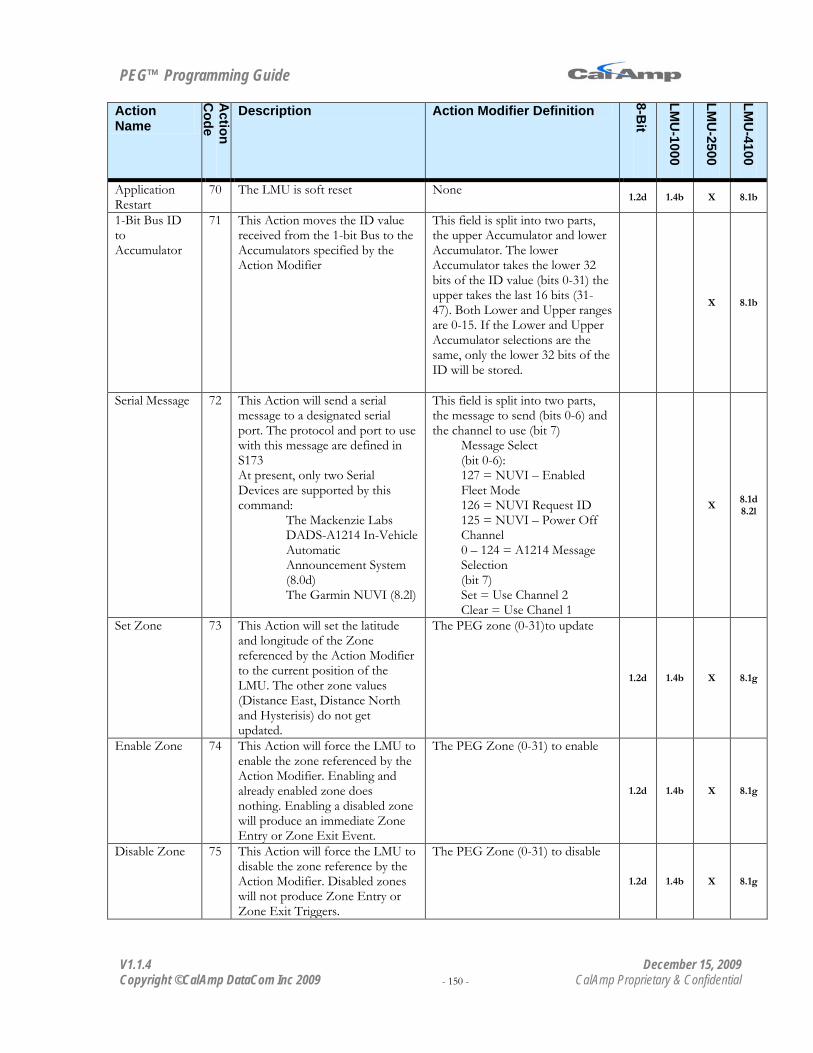
PEG™ Programming Guide
V1.1.4 December 15, 2009 Copyright ©CalAmp DataCom Inc 2009 - 150 - CalAmp Proprietary & Confidential
Action Name
Action
Code
Description Action Modifier Definition
8-Bit
LMU
-1000
LMU
-2500
LMU
-4100
Application Restart
70 The LMU is soft reset None 1.2d 1.4b X 8.1b
1-Bit Bus ID to Accumulator
71 This Action moves the ID value received from the 1-bit Bus to the Accumulators specified by the Action Modifier
This field is split into two parts, the upper Accumulator and lower Accumulator. The lower Accumulator takes the lower 32 bits of the ID value (bits 0-31) the upper takes the last 16 bits (31-47). Both Lower and Upper ranges are 0-15. If the Lower and Upper Accumulator selections are the same, only the lower 32 bits of the ID will be stored.
X 8.1b
Serial Message 72 This Action will send a serial message to a designated serial port. The protocol and port to use with this message are defined in S173 At present, only two Serial Devices are supported by this command:
The Mackenzie Labs DADS-A1214 In-Vehicle Automatic Announcement System (8.0d) The Garmin NUVI (8.2l)
This field is split into two parts, the message to send (bits 0-6) and the channel to use (bit 7)
Message Select (bit 0-6): 127 = NUVI – Enabled Fleet Mode 126 = NUVI Request ID 125 = NUVI – Power Off Channel 0 – 124 = A1214 Message Selection (bit 7) Set = Use Channel 2 Clear = Use Chanel 1
X 8.1d 8.2l
Set Zone 73 This Action will set the latitude and longitude of the Zone referenced by the Action Modifier to the current position of the LMU. The other zone values (Distance East, Distance North and Hysterisis) do not get updated.
The PEG zone (0-31)to update
1.2d 1.4b X 8.1g
Enable Zone 74 This Action will force the LMU to enable the zone referenced by the Action Modifier. Enabling and already enabled zone does nothing. Enabling a disabled zone will produce an immediate Zone Entry or Zone Exit Event.
The PEG Zone (0-31) to enable
1.2d 1.4b X 8.1g
Disable Zone 75 This Action will force the LMU to disable the zone reference by the Action Modifier. Disabled zones will not produce Zone Entry or Zone Exit Triggers.
The PEG Zone (0-31) to disable
1.2d 1.4b X 8.1g

PEG™ Programming Guide
V1.1.4 December 15, 2009 Copyright ©CalAmp DataCom Inc 2009 - 151 - CalAmp Proprietary & Confidential
Action Name
Action
Code
Description Action Modifier Definition
8-Bit
LMU
-1000
LMU
-2500
LMU
-4100
Dial Number 76 This command will force the LMU to dial a phone number to establish a voice call. This Action is only available on iDEN devices
The index of the short text string containing the phone number to dial (0-15) 1.4b X 8.2a
Answer 77 This Action will force the LMU to answer an incoming voice call. This Action is only available on iDEN devices
None
1.2h 1.4b X 8.2a
Hang-Up 78 This Action will force the LMU to hang-up and active voice call. It should have no effect on the data session. This Action is only available on iDEN devices
None
1.2h 1.4b X 8.2a
Set PEG State Variable
79 This Action will set the PEG State Variable to the value referenced in the Action Modifier
The value of the PEG State variable: 0- 255 1.2d X 8.2g
Multi-Pulse Output
80 This action will pulse an output for 0.5s in the pattern defined by the Action Modifier
This value is split into two parts, the output to be pulsed and the number of pulses. bit 4-7 = Output to Pulse
0 = Output 0 1 = Output 1 . . . 6 = Output 6
bit 0-3 = The number of pulses 0 - 15
1.2d X 8.2g
Send Mini Report
81 The LMU will send a Mini Event report with the Event Code value set to the Action Modifier. The message will be sent in Store and Forward Mode
The Event Code for the Event report (0-255)
1.2d X 8.2g
Log Mini Report
82 The LMU will Log a Mini Event report with the Event Code value set to the Action Modifier. The message will be sent in Batch mode if the Log is not already in Store and Forward mode.
The Event Code for the Event report (0-255)
1.2d X 8.2g
Send-Unacknowledged Mini Report
83 The LMU will send an unacknowledged Mini Event report with the Event Code value set to the Action Modifier.
The Event Code for the Event report (0-255) 1.2d X 8.2g

PEG™ Programming Guide
V1.1.4 December 15, 2009 Copyright ©CalAmp DataCom Inc 2009 - 152 - CalAmp Proprietary & Confidential
Action Name
Action
Code
Description Action Modifier Definition
8-Bit
LMU
-1000
LMU
-2500
LMU
-4100
Start Max Acceleration Accumulator
84 The LMU will sample its maximum acceleration value into the Accumulator referenced by the Action Modifier. The acceleration will be in cm/s2
The Accumulator to place the acceleration value in.
0 = Accumulator 0 1 = Accumulator 1 2 = Accumulator 2 3 = Accumulator 3 . . . 14 = Accumulator 14 15 = Accumulator 15
X 8.2g
Start Max Deceleration Accumulator
85 The LMU will sample its maximum deceleration value into the Accumulator referenced by the Action Modifier. The deceleration will be in cm/s2
The Accumulator to place the deceleration value in.
0 = Accumulator 0 1 = Accumulator 1 2 = Accumulator 2 3 = Accumulator 3 . . . 14 = Accumulator 14 15 = Accumulator 15
X 8.2g
Start RSSI Accumulator
86 The LMU will sample the current RSSI value into the Accumulator referenced by the Action Modifier. The value is offset by +200dBm. For example an RSSI of -90 will show a value of 110.
The Accumulator to place the RSSI value in.
0 = Accumulator 0 1 = Accumulator 1 2 = Accumulator 2 3 = Accumulator 3 . . . 14 = Accumulator 14 15 = Accumulator 15
1.2d X 8.2h
Start Cell ID Accumulator
87 The LMU will sample the current Cell ID and Base Station ID for the network the LMU is communicating with. The accumulator will be split into two parts. Bits 0 – 15 will be the Cell Site ID, Bits 16 – 31 will contain the Base Station ID This feature does not apply to CDMA or iDEN devices.
The Accumulator to place the Cell ID value in.
0 = Accumulator 0 1 = Accumulator 1 2 = Accumulator 2 3 = Accumulator 3 . . . 14 = Accumulator 14 15 = Accumulator 15
X 8.2l

PEG™ Programming Guide
V1.1.4 December 15, 2009 Copyright ©CalAmp DataCom Inc 2009 - 153 - CalAmp Proprietary & Confidential
Action Name
Action
Code
Description Action Modifier Definition
8-Bit
LMU
-1000
LMU
-2500
LMU
-4100
Divide Accumulators
88 This action will divide the value of one accumulator by the value of the next. The result shall be placed in a third accumulator. Note that results shall be truncated. Dividend / Divisor = Quotient ACC (N) / ACC (N +1) = ACC (M)
This field is split into two parts, the accumulator containing the dividend and the accumulator to place the quotient. bit 4-7 = Quotient Accumulator
0 = Accumulator 0 1 = Accumulator 1 2 = Accumulator 2 3 = Accumulator 3 . . . 14 = Accumulator 14 15 = Accumulator 15
bit 0-3 = Dividend Accumulator 0 = Accumulator 0 1 = Accumulator 1 2 = Accumulator 2 3 = Accumulator 3 . . . 14 = Accumulator 14 15 = Accumulator 15
The divisor is contained in the next accumulator after the dividend.
X 8.2l
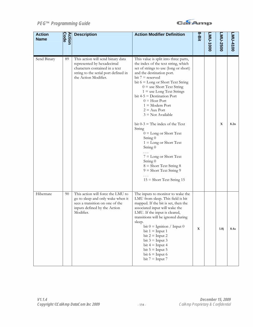
PEG™ Programming Guide
V1.1.4 December 15, 2009 Copyright ©CalAmp DataCom Inc 2009 - 154 - CalAmp Proprietary & Confidential
Action Name
Action
Code
Description Action Modifier Definition
8-Bit
LMU
-1000
LMU
-2500
LMU
-4100
Send Binary 89 This action will send binary data represented by hexadecimal characters contained in a text string to the serial port defined in the Action Modifier.
This value is split into three parts, the index of the text string, which set of strings to use (long or short) and the destination port. bit 7 = reserved bit 6 = Long or Short Text String
0 = use Short Text String 1 = use Long Text Strings
bit 4-5 = Destination Port 0 = Host Port 1 = Modem Port 2 = Aux Port 3 = Not Available
bit 0-3 = The index of the Text String
0 = Long or Short Text String 0 1 = Long or Short Text String 0 . . . 7 = Long or Short Text String 0 8 = Short Text String 8 9 = Short Text String 9 . . . 15 = Short Text String 15
X 8.2n
Hibernate 90 This action will force the LMU to go to sleep and only wake when it sees a transition on one of the inputs defined by the Action Modifier.
The inputs to monitor to wake the LMU from sleep. This field is bit mapped. If the bit is set, then the associated input will wake the LMU. If the input is cleared, transitions will be ignored during sleep.
bit 0 = Ignition / Input 0 bit 1 = Input 1 bit 2 = Input 2 bit 3 = Input 3 bit 4 = Input 4 bit 5 = Input 5 bit 6 = Input 6 bit 7 = Input 7
X 1.0j 8.4a

PEG™ Programming Guide
V1.1.4 December 15, 2009 Copyright ©CalAmp DataCom Inc 2009 - 155 - CalAmp Proprietary & Confidential
Action Name
Action
Code
Description Action Modifier Definition
8-Bit
LMU
-1000
LMU
-2500
LMU
-4100
Start Temperature Accumulator
91 The LMU will sample the current Temperature value received from the 1Bit-Bus into the Accumulator referenced by the Action Modifier. The value will have a 0.0625 °C LSB. .
The Accumulator to place the Temperature value in.
0 = Accumulator 0 1 = Accumulator 1 2 = Accumulator 2 3 = Accumulator 3 . . . 14 = Accumulator 14 15 = Accumulator 15
1.0j
Request Time Sync
92 The LMU will send a Time Sync request (i.e. LM Direct App Message Type 50) to the server specified by the Action Modifier
The server to obtain time-sync from:
0 = Request from Maintenance Server (i.e. PULS) 1 = Request from Inbound Server
1.1a 8.4a
Move Temperature Sensor Count to Accumulator
93 This action will cause the LMU to count the number of temperature sensors connected to the 1Bit Bus into the accumulator specified by the Action Modifier.
The Accumulator to place the Temperature sensor count in.
0 = Accumulator 0 1 = Accumulator 1 2 = Accumulator 2 3 = Accumulator 3 . . . 14 = Accumulator 14 15 = Accumulator 15
1.1a