Embed Size (px)
Citation preview

PDVSAINTEVEP
Accumulation Process and Phenomena in Chamber Lift Completions
Accumulation Process and Phenomena in Chamber Lift Completions
Sergio Caicedo
ASME/API Gas-Lift Workshop Houston, Texas, Spring 2002

PDVSAINTEVEP
Accumulation Process and Phenomena in Chamber Lift Completions
OUTLINE
•Introduction•Two-packer Chamber Equations•Insert Chamber Equations•Algorithm•Results•Conclusions•Recommendations

PDVSAINTEVEP
Accumulation Process and Phenomena in Chamber Lift Completions
Chamber Lift Application Window
Particularly suitable for wells with very low reservoir pressure, high productivity
Chamber Lift Design Goal
Accumulate more liquid volume per bottom hole flowing pressure
Chamber Lift Main Problem
Formation Gas in the chamber
INTRODUCTION

PDVSAINTEVEP
Accumulation Process and Phenomena in Chamber Lift Completions
Production Cycle
Accumulation Stage
• Liquid Accumulation In Annulus and Tubing• Formation Gas Accumulation in Annulus• Described by Gas and Liquid balance coupled with
Reservoir inflow
Chamber DisplacementSlug LiftingVenting
INTRODUCTION

PDVSAINTEVEP
Accumulation Process and Phenomena in Chamber Lift Completions
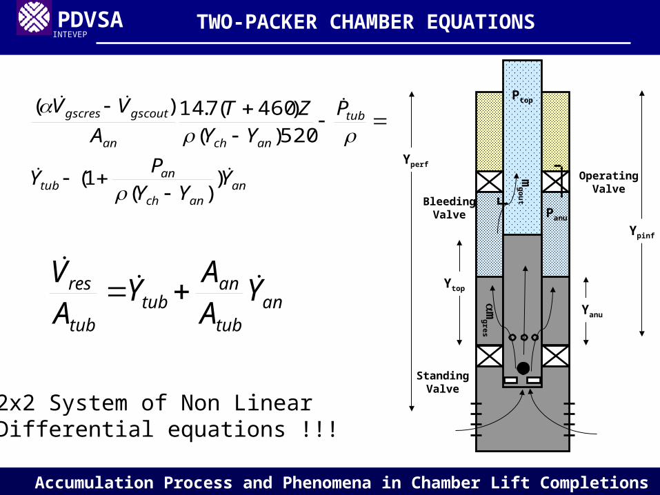
TWO-PACKER CHAMBER COMPLETION
TWO-PACKER CHAMBER EQUATIONS

PDVSAINTEVEP
Accumulation Process and Phenomena in Chamber Lift Completions
anutubres VVV
dtZRTMVPd
mm wanangoutgin
)/(
anantubtop YPYP
Gas Balance in the annulus
Liquid Balance
Pressure relationship
TWO-PACKER CHAMBER EQUATIONS
Panu
Ptop
Yanu
Ytop
BleedingValve
OperatingValve
mgou
t
m
gres
StandingValve
Yperf
Ypinf
PDVSAINTEVEP
Accumulation Process and Phenomena in Chamber Lift Completions
antub
antub
tub
res YAA
YAV
ananch
antub
tub
anchan
gscoutgscres
YYY
PY
PYY
ZTA
VV
))(
1(
520)()460(7.14)(
2x2 System of Non LinearDifferential equations !!!
TWO-PACKER CHAMBER EQUATIONS
Panu
Ptop
Yanu
Ytop
BleedingValve
OperatingValve
mgou
t
m
gres
StandingValve
Yperf
Ypinf

PDVSAINTEVEP
Accumulation Process and Phenomena in Chamber Lift Completions
)( infpperftubtopwf YYYPP
)8.02.01(3600*24
615.53600*24
615.52
2
res
wf
res
wfmaxresres P
P
P
PQQV
),,(3600*24 oriftubanscdorif
gscout DPPfQ
V
Reservoir Inflow
Bottom Hole Flowing Pressure
Gas rate through the Bleeding Valve
TWO-PACKER CHAMBER EQUATIONS
Panu
Ptop
Yanu
Ytop
BleedingValve
OperatingValve
mgou
t
m
gres
StandingValve
Yperf
Ypinf

PDVSAINTEVEP
Accumulation Process and Phenomena in Chamber Lift Completions
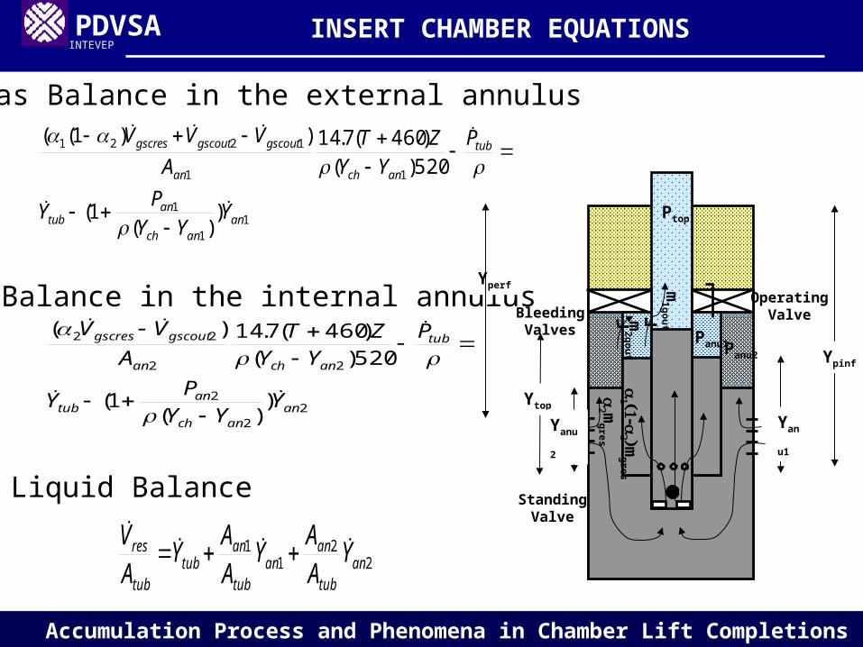
INSERT CHAMBER COMPLETION
INSERT CHAMBER EQUATIONS
PDVSAINTEVEP
Accumulation Process and Phenomena in Chamber Lift Completions
22
11
antub
anan
tub
antub
tub
res YAA
YAA
YAV
11
1
11
1221
))(
1(
520)()460(7.14))1((
ananch
antub
tub
anchan
gscoutgscoutgscres
YYY
PY
PYY
ZTA
VVV
22
2
22
22
))(
1(
520)()460(7.14)(
ananch
antub
tub
anchan
gscoutgscres
YYY
PY
PYY
ZTA
VV
Gas Balance in the external annulus
Gas Balance in the internal annulus
Liquid Balance
INSERT CHAMBER EQUATIONS
Yperf
Panu1
Ptop
Yan
u1
Ytop
BleedingValves
OperatingValve
m1gou
t
mgres
Panu2
m
gres
m2gou
t
Yanu
2
StandingValve
Ypinf

PDVSAINTEVEP
Accumulation Process and Phenomena in Chamber Lift Completions
),,(3600*24 11
11 oriftuban
scdorifgscout DPPf
QV
),,(3600*24 212
22 orifanan
scdorifgscout DPPf
QV
Gas rate through the Bleeding Valves
INSERT CHAMBER EQUATIONS
Yperf
Panu1
Ptop
Yan
u1
Ytop
BleedingValves
OperatingValve
m1gou
t
mgres
Panu2
m
gres
m2gou
t
Yanu
2
StandingValve
Ypinf

PDVSAINTEVEP
Accumulation Process and Phenomena in Chamber Lift Completions
n
n
nan
ntub
n
n
n
n
b
b
Y
Y
a
a
a
a
2
1
22
12
21
11
tYYY ntub
ntub
ntub 1
tYYY nan
nan
nan 1
111 nan
ntubtop
nan YYPP
ttt nn 1
ALGORITHM

PDVSAINTEVEP
Accumulation Process and Phenomena in Chamber Lift Completions
The key to simulate the accumulation process in both cases is to introduce the proper initial conditions and suitable boundary or limit conditions.
For instance, the initial level in the annulus is zero because all the liquid has been displaced during the previous injection stage, meanwhile the initial liquid level depends on the fall back of the slug in the previous production cycle.
Among the limit conditions, the limit when the liquid level in the annulus approaches zero requires special care in order to keep the system consistent.
INITIAL AND BOUNDARY CONDITIONS

PDVSAINTEVEP
Accumulation Process and Phenomena in Chamber Lift Completions
Liquid Levels vs. Time for a 100-feet two-packer chamber with a 3/16" bleeding port and 10% of gas coming into the annulus
RESULTS
Nivel de fluido en el anular y en tuberia vs Tiempo
0
100
200
300
400
500
0 200 400 600 800 1000 1200 1400
T (seg)
Co
lum
na
(p
ies)
Yan
Ytub
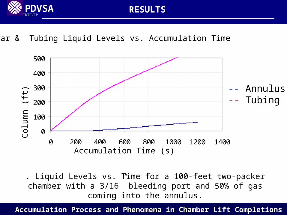
Annular & Tubing Liquid Levels vs. Accumulation TimeC
olum
n (f
t)
Accumulation Time (s)
-- Annulus-- Tubing

PDVSAINTEVEP
Accumulation Process and Phenomena in Chamber Lift Completions
Liquid Levels vs. Time for a 100-feet two-packer chamber with a 1/32” bleeding port and 10% of gas coming into the annulus.
Nivel de fluido en el anular y en tuberia vs Tiempo
0
100
200
300
400
500
0 200 400 600 800 1000 1200 1400
T (seg)
Co
lum
na
(p
ies)
Yan
Ytub
Annular & Tubing Liquid Levels vs. Accumulation Time C
olum
n (f
t)
Accumulation Time (s)
RESULTS
-- Annulus-- Tubing
PDVSAINTEVEP
Accumulation Process and Phenomena in Chamber Lift Completions
. Liquid Levels vs. Time for a 100-feet two-packer chamber with a 3/16” bleeding port and 50% of gas coming into the annulus.
Nivel de fluido en el anular y en tuberia vs Tiempo
0
100
200
300
400
500
0 200 400 600 800 1000 1200 1400
T (seg)
Co
lum
na
(p
ies)
Yan
Ytub
Annular & Tubing Liquid Levels vs. Accumulation Time
Col
umn
(ft)
Accumulation Time (s)
RESULTS
-- Annulus-- Tubing

PDVSAINTEVEP
Accumulation Process and Phenomena in Chamber Lift Completions
Liquid Levels vs. Time for a 200-feet Insert Chamber with a 3/16” internal and external bleeding ports.
Annular & Tubing Liquid Levels vs. Accumulation Time C
olum
n (f
t)
Accumulation Time (s)
RESULTS
-- Annulus1-- Annulus2 -- Tubing

PDVSAINTEVEP
Accumulation Process and Phenomena in Chamber Lift Completions
Liquid Levels vs. Time for a 200-feet Insert Chamber with a 3/16” internal and a 1” external bleeding ports
Annular & Tubing Liquid Levels vs. Accumulation Time
Col
umn
(ft)
Accumulation Time (s)
RESULTS
-- Annulus1-- Annulus2 -- Tubing

PDVSAINTEVEP
Accumulation Process and Phenomena in Chamber Lift Completions
Liquid Levels vs. Time for a 200-feet Insert Chamber with 1" internal and external bleeding ports
Annular & Tubing Liquid Levels vs. Accumulation Time
Col
umn
(ft)
Accumulation Time (s)
RESULTS
-- Annulus1-- Annulus2 -- Tubing
PDVSAINTEVEP
Accumulation Process and Phenomena in Chamber Lift Completions
11
1
11
121
))(
1(
520)()460(7.14))1((
ananch
antub
tub
anchan
gscoutgscres
YYY
PY
P
YYZT
A
VV
22
2
22
22
))(
1(
520)()460(7.14)(
ananch
antub
tub
anchan
gscoutgscres
YYY
PY
PYY
ZTA
VV
),,(3600*24 22
22 oriftuban
scdorifgscout DPPf
QV
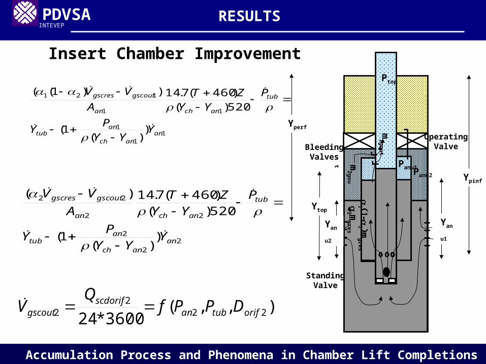
Insert Chamber Improvement
RESULTS
Panu1
Ptop
Yan
u1
Ytop
BleedingValves
OperatingValve
m1gou
t
mgres
Panu2
m
gresm
2gout
Yan
u2
StandingValve
Yperf
Ypinf

PDVSAINTEVEP
Accumulation Process and Phenomena in Chamber Lift Completions
Liquid Levels vs. Time for a 200-feet Insert Chamber with a 3/16" internal and a 1/2" external bleeding ports
Annular & Tubing Liquid Levels vs. Accumulation Time
Col
umn
(ft)
Accumulation Time (s)
RESULTS
-- Annulus1-- Annulus2 -- Tubing

PDVSAINTEVEP
Accumulation Process and Phenomena in Chamber Lift Completions
The complexity of the accumulation process in chamber lift requires the previous analysis for a better sizing of the bleeding valves.
The coherence and physical behavior of the results along with the field experiences backups the theoretical model and the numerical method.
The slight differences between the two-packer and insert chambers completions do not allow applying the same practices in both installations.
CONCLUSIONS

PDVSAINTEVEP
Accumulation Process and Phenomena in Chamber Lift Completions
In insert chamber completions it is highly recommended to connect directly the external annulus with the tubing whether it is possible.
Apply the model developed in this paper when designing or simulating wells with two-packer or insert chamber lift installations.
Start a research work in order to determine the gas percentages of separation that flow into the annulus and tubing in chamber lift installations in order to include that key information in the presented model.
RECOMMENDATIONS

PDVSAINTEVEP
Accumulation Process and Phenomena in Chamber Lift Completions
QUESTIONS ???
FEEL FREE PLEASE

PDVSAINTEVEP
Accumulation Process and Phenomena in Chamber Lift Completions
Thanks for your attentionThanks for your attention