Embed Size (px)
Citation preview

Electrical and Electronic Engineering 2012, 2(6): 362-373 DOI: 10.5923/j.eee.20120206.04
Design and Analysis of MEMS based Composite Piezoelectric Ultrasonic Transducer
T. Satyanarayana1, G. Srinivas2, M V V K Srinivas Prasad2 , Y. Srinivas3 , B. Sudheer4, K. Srinivasa Rao1,*
1Department of Electronics & Instrumentation Engineering, Lakireddy Balireddy College of Engineering, Mylavaram, 521 230, Andhra Pradesh, India
2Department of Physics, KL University, Vadeswaram, Guntur District, Andhra Pradesh, India 3Department of Computer Science, GITAM University, Hyderabad, India
4Department of Mechanical Engineering, Lakireddy Balireddy College of Engineering, Mylavaram, 521 230, Andhra Pradesh, India
Abstract With the rapid growth of technology, micro scale devices are p laying a dominant role in mechanical and optoelectronic devices. Characteristics like min iaturization, mult iplicity and microelectronics help these devices to sense, control and actuate on micro scale with effects on macro scale. Micro devices like composite transducers are widely used in medical, industrial and space applications because they are relatively simple and easy to interface with other devices and also provide better resolution and easy installation. The present work reports the design and simulat ion of composite piezoelectric ultrasonic transducer, where susceptance was computed by applying AC potential for various piezoceramic materials i.e., Nepec 6, Quartz, Pzt-8. In this, an eigen frequency analysis is fo llowed by a frequency response analysis to calculate the input admittance as a function of the excitation frequency. To make this design, COMSOL Mult iphysics software is used. The transducer designed with PZT-8 has exh ibited better sensitivity than others. These transducers are widely used in non-destructive testing (NDT), weld ing, machin ing, medical imaging etc.
Keywords MEMS Composite Transducer, Susceptance Analysis, COMSOL Multiphysics 4.2a
1. Introduction Control is more important than information processing; it
implies that there is a d irect interaction with the physical world. Control systems include sensors and actuators, which help us to ensure that automat ion systems can manage activities and environments in desired ways. In this context MEMS has been identified as one of the most promising technologies for the 21st Century and has the potential to revo lut ion ize both industrial and consumer p roducts by c o mb in in g s i l ico n -bas e d mic r oe le ct ron ics w i th micromachining technology[1-7]. They usually consist of a central unit that processes data, the microprocessor and several components that interact with the outside such as micro sensors[8-9]. Th is techniques use micro system-based devices that have the potential to dramatically effect of all of our lives and the way we live by p roviding the min iaturized devices. A micro- electromechanical system (MEMS) is a process technology used to create tiny integrated devices or systems that combine mechanical and electrical components. They are fabricated us ing integrated circu it (IC) batch processing techniques and can range in s ize from a few
* Corresponding author: [email protected] (K. Srinivasa Rao) Published online at http://journal.sapub.org/eee Copyright © 2012 Scientific & Academic Publishing. All Rights Reserved
micrometres to millimetres. These devices (or systems) have the ability to sense, control and actuate on the micro scale, and generate effects on the macro scale. In this context, there has been increasing demand for ultrasonic transducers due to its potential applications, including non-destructive testing (NDT), welding machining, cleaning, underwater communicat ion, navigation, map building, ultrasonic surgery, etc. Among different types of transducers viz., sonic, ultrasonic and mega sonic, ultrasonic transducers usually work at a frequency range from 20 kHz to 200 kHz[10]. Features like high acoustic efficiency, mechanical flexibility, low mechanical Q, low cross talk and low acoustic impedance made these transducers to be used in wide range of applications. Generally this sensor works by emitting a short burst of 40 kHz u ltrasonic sound from a p iezoelectric transducer. Ultrasonic transducer playsan important ro le in both generating and receiving ultrasound in an ultrasonic measurement system. In general, they are complex electromechanical devices that are difficu lt to characterize and design. The sensitivity and resolution of the device entirely depend upon the piezocomposite materials being used. There are h igh resolutions producing devices in the market which are built by using lead metaniobate piezoceramic o r piezoelectric polymers. But these are showing low sensitivity as most of the acoustic energy is absorbed in the backing and materials efficiency is lowered. As these transducers involve both the combination of

363 Electrical and Electronic Engineering 2012, 2(6): 362-373
electrical and mechanical components, it is difficult to for us to analyse them. Whereas a Piezoelectric ceramic and a passive polymer are combined to get a piezo composite, which helps us to design the transducer that is producing better results than the conventional piezoelectric devices[11]
Thus, the present study is mainly focused on design of composite piezoelectric u ltrasonic transducer with three different piezoelectric materials and computation of susceptance as a function of excitation frequency for the proposed structure.
2. Theoretical Background To generate and measure the ultrasonic pulses, the
composite transducer is working based on the phenomenon of piezoelectric effect. Piezoelectric ceramics and single crystal materials are the two main materials which are used for generation of piezoelectric effect in the transducers. Lead zirconate titanate, also called PZT is the most common piezoelectric ceramic which is used today along with other materials like sodium tungstates, lithium tantalite, lead titanate, zinc oxide, barium t itanate and barium strontium titanate. On the other hand single crystal materials like magnesium niobate-lead titanate are also used in manufacturing of these transducers along with gallium phosphate, quartz and tourmaline. These crystals provide the flexib ility in designing, so that they can be made into various shapes to achieve different vibration modes, which help the transducer in operating from low kHz range up to the MHz range. The piezoelectric effects generated when mechanical stress is applied between surfaces of a solid dielectric. Conversely when a voltage is applied across certain surfaces of a solid then it undergoes a mechanical distortion and exhibits the piezoelectric effect. As piezoelectricity is the combined effect of the electrical behaviour of the material i.e.,
D = ЄE (1) Where D is the electric charge density displacement
(electric d isplacement), ε is permittiv ity and E is electric field strength. Linear elasticity equations are coupled with electrostatic charge equations by means of electric constants to obtain a reasonable model of this interaction. So the stress charge form of equations is as follows
T = CE . S - et . E (2) D = e . S + ЄS . E (3)
Where S is the stress, et is the permittivity at constant strain, T is the stress. When stress is applied these crystals bends in different ways at different frequencies, but they will be resonating within narrow frequency ranges. Some of the transducers which use the piezoelectric materials are phonograph cartridges, microphones, and strain gauges that produce an electrical output from a mechanical input. But a mechanical output from an electrical input can be observed in earphones and ultrasonic transmitters. Generally
electrostatic transducers have very high initial cost and very low system resistance but whereas piezo transducers are less expensive thereby making its construction best suited for harsh environments.
3. Use of Comsol Multiphysics The software package selected to model and simulate the
MEMS composite ultrasonic transducer was COMSOL Multiphysics Version 4.2 a.It is a powerful interactive environment fo r modelling and Multiphysics were selected because there was previous experience and expertise regarding its use as well as confidence in its capabilities. This provides the flexib ility of selecting the required vertex for applying the inputs by rotating the geometry in the work plane. This consists of material library where we can find different material branches like MEMS, semiconductors(GaAs, Ge¸C[100] etc), insulators(Al2 O3,Si2 O3), polymers and piezoelectric (Barium sodium niobate, Lithium niobate, Lead zirconate titanate etc) can be selected.
4. Design Process The design of composite piezoelectric transducer starts
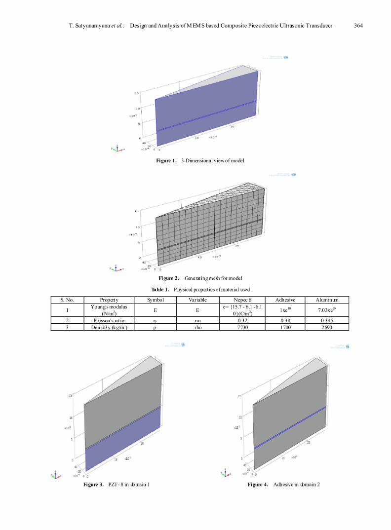
from defin ing parameters for the required geometry, selection of necessary material and addition of physical interfaces. For modelling, certain instructions must be followed. First, selection of piezo electric devices (pzd) and then eigenfrequency analysis was chosen. For required shape, first circle with radius 27.5e- 3m. Later, bezier polygon is chosen and its segments are located in the control point sub section by adding the value of x in row 2 for about 0.03 in the add linear button. Now this structure is rotated for about 10 degrees and converted to solid. To reduce memory requirements, we use the structural symmetry by cutting along its mid plane which is perpendicular to central axis. After cutting the geometry, now by locating the points from the work p lane, the final 3-D model can be obtained as shown in Fig. 1. Variables must be defined for the susceptance so the compensating factors, symmetry and degree of wedge is taken into consideration, from which mesh can be generated as shown in Fig. 2.
The composite piezoelectric ultrasonic device has a cylindrical geometry. This model consists of a piezoceramic (NEPEC 6)and two Langevin type transducers in which a disk is sandwiched between a pair of alumin ium d isks by means of adhesive (ARALDITE) i.e., the layers are organized as follows alumin ium layer-adhesive layer-piezoceramic layer-adhesive layer- alumin ium layer. During the modelling of the geometry, domains must be selected so that the required material can be inserted in the proper area and they are as follows.
T. Satyanarayana et al.: Design and Analysis of MEMS based Composite Piezoelectric Ultrasonic Transducer 364
Figure 1. 3-Dimensional view of model
Figure 2. Generating mesh for model
Table 1. Physical properties of material used
S. No. Property Symbol Variable Nepec 6 Adhesive Aluminum
1 Young's modulus (N/m2) E E e= 15.7 - 6.1 -6.1
0(C/m2) 1xe10 7.03xe10
2 Poisson's ratio σ nu 0.32 0.38 0.345 3 Densit3y (kg/m ) ρ rho 7730 1700 2690
Figure 3. PZT- 8 in domain 1
Figure 4. Adhesive in domain 2

365 Electrical and Electronic Engineering 2012, 2(6): 362-373
Figure 5. Aluminium in domain 3
This type of construction is used for sonar transducers and is of practical importance because it provides design flexib ility by choosing material combinations and dimensions[12]. One of the p iezoceramic materials, lead zirconate titanate is most popular choice for medical ultrasonic transducer. This offer high electromechanical coupling a wide selection of dielectric constants which made pzt-8 prominent in selection during the construction of medical transducers. The material constants used during the design of transducer are tabulated in Table 1.
4.1. Input Parameters
Calculating the susceptance for the geometry requires selection of the boundary conditions for the terminal, ground and symmetry position so that the input parameters can be applied. Here as we are modelling only for the upper part of the transducer, this condition lead to the application o f the potential fo r about half of the total peak value i.e., 0.5 volts.
Electrical terminal is selected in boundary 6 so that the voltage can be applied to it fo rm terminal type. Where the ground is selected to boundary 3 from electrical boundary conditions. The condition for satisfying the symmetry is made by select ing the boundaries in the model from 1-5, 7, and 8.The expression for these conditions are given by equations,
1). Terminal ∫∂Ωρsds=Q0. 2). Ground V = 0. 3). Symmetry n.u = 0. Linear elastic material model is used here for which
equation is given by C = C (E, V), in which E represents young's modulus and V for Poisson's ratio.
Figure 6. Boundary for ground
5. Simulation Simulation comprises of two phases, where in first one
lowest eigen modes are calculated by rep lacing the expression of displacement field and the other one involves the application of the frequency swept. Deformat ions are observed after the expression is replaced to susceptance. Since we applied AC potential between the electrical terminals on both sides of the electrode surface, the imaginary part of the admittance i.e., susceptance is calculated. This can be computed by knowing the ratio of total current applied and voltage supplied for the given structure. Where the maximum allowed potential is one volt peak for the first four lowest eigen frequency.
6. Results and Discussion Using software, two kinds of studies has been explored i.e.,
study 1 for calculat ion of the lowest eigen modes, Whereas the study 2 corresponds to the frequency domain case in which frequency swept is noted down for the first four eigen frequencies. The range of the frequency is given form 20e3 to106e3 and for a step about 2e3 deformation is observed by plotting on the material. Now the displacement field , Z component is selected form the solid mechan ics of piezoelectric devices by rep lacing the expression of surface 1. Eigen modes and slices of deformations are observed by plotting the surface 1 for three different materials, which are shown in Figure 7 and 8. Total d isplacement can be observed for the model, after the app licat ion of the frequency swept. Later slices are formed for the model which helps in analysing the internal deformation. 1- Dimensional graph is obtained by replacing the expression to susceptance for the vertex one, which shows the relat ion between the susceptance and frequency.

T. Satyanarayana et al.: Design and Analysis of MEMS based Composite Piezoelectric Ultrasonic Transducer 366
a) Results obtained when Nepec 6 material is used
b) Results obtained when Quartz material is used

367 Electrical and Electronic Engineering 2012, 2(6): 362-373
c) Results obtained when PZT - 8 material is used
Figure 7. Lowest vibration eigen mode of the transducer (3-D plot group 1)
a) Results obtained when Nepec 6 material is used

T. Satyanarayana et al.: Design and Analysis of MEMS based Composite Piezoelectric Ultrasonic Transducer 368
b) Results obtained when Quartz material is used
c) Results obtained when PZT - 8 material is used Figure 8. Slices of transducer (3-D Plot group 2)
The first material we considered for analysis was Nepec 6 where the min imum and maximum deformat ions are -1.7719x10⁻⁸ and 2.2744x10⁻⁷ respectively for the eigenfrequency 43196.272163, which is shown in Fig. 7a. But when Quartz was used the deformation values for minimum and maximum are 5.066x10⁻¹⁰ and -52589x10-8 respectively, which can be observed in Fig. 7b. When Pzt-8 is subjected to test for computation of eigen modes, the deformation can be noted from Fig. 9c which shows the min imum to maximum range i.e., from-1.3853x10⁻⁸ and 2.5187x10⁻⁷ for the eigenfrequency 44869.06253.
After the applicat ion of frequency swept the min imum and maximum values of deformation for Nepec 6 are in the range

369 Electrical and Electronic Engineering 2012, 2(6): 362-373
of 0 to 9.2582x10⁻¹⁰, which was shown in Fig. 9a. Whereas when Quartz was taken into consideration the min imum and maximum values of deformat ion are -5.19x10⁻¹⁹ and 3.5214x10⁻¹⁹, which can be observed in Fig. 9b. On the other hand Fig. 9c corresponds to Pzt-8 results, in which the deformat ion values for min imum and maximum are in the range of-2.4778x10⁻⁸ and 0.
a) Results obtained when Nepec 6 material is used
b) Results obtained when Quartz material is used

T. Satyanarayana et al.: Design and Analysis of MEMS based Composite Piezoelectric Ultrasonic Transducer 370
c) Results obtained when PZT - 8 material is used.
Figure 9. Deformation for the frequency Swept (3-D plot group 3)
a) Results obtained when Nepec 6 material is used.
371 Electrical and Electronic Engineering 2012, 2(6): 362-373
b) Results obtained when Quartz material is used.
c) Results obtained when PZT - 8 material is used.
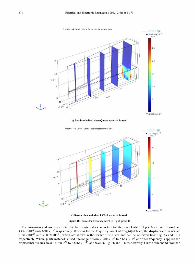
Figure 10. Slices for frequency swept (3-D plot group 4)
The min imum and maximum total displacements values in meters for the model when Nepec 6 material is used are 4.4729x10⁻⁸ and2.6688x10-7 respectively. Whereas for the frequency swept of freq(44)=1.60e5, the displacement values are 5.8919x10⁻¹² and 9.0897x10⁻¹⁰ , which are shown in the form of the slices and can be observed from Fig. 8a and 10 a respectively. When Quartz material is used, the range is from 9.3404x10⁻⁹ to 5.6433x10⁻⁸ and after frequency is applied the displacement values are 8.3578x10⁻²² to 2.8866x10⁻¹⁹,as shown in Fig. 8b and 10b respectively. On the other hand, from the
T. Satyanarayana et al.: Design and Analysis of MEMS based Composite Piezoelectric Ultrasonic Transducer 372
Fig. 8c and 11c, Pzt-8 resulted in the displacement range from 4.8305x10⁻⁸ to 2.7847x10⁻⁷, whereas after application of frequency, the minimum to maximum displacement range is from 2.3308x10⁻¹⁰ to 2.3358x10⁻⁸ respectively.
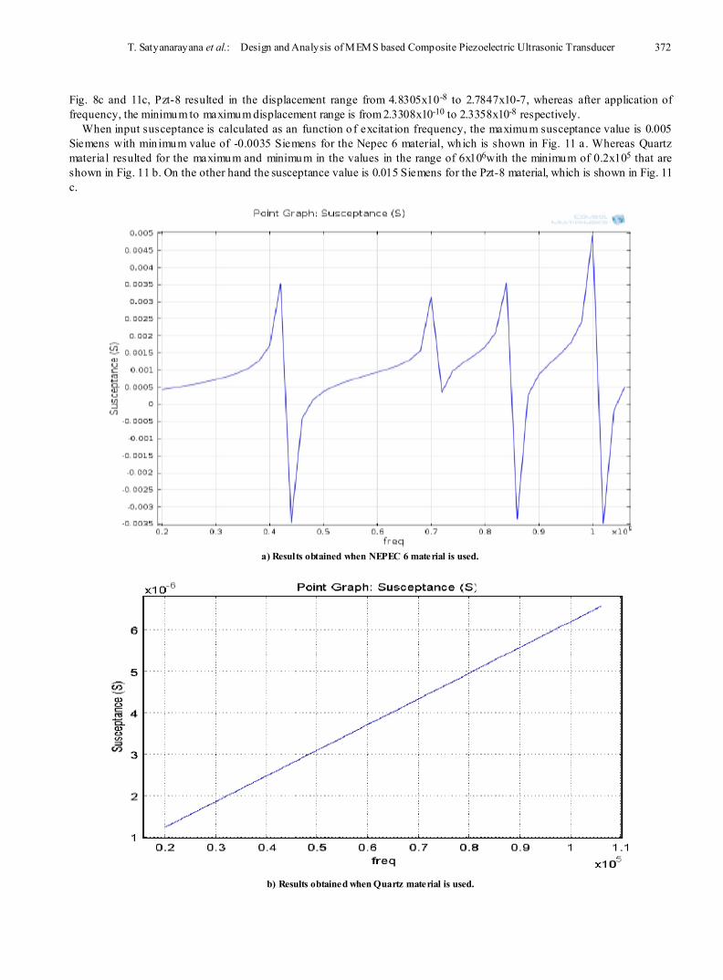
When input susceptance is calculated as an function o f excitat ion frequency, the maximum susceptance value is 0.005 Siemens with min imum value of -0.0035 Siemens for the Nepec 6 material, which is shown in Fig. 11 a. Whereas Quartz material resulted for the maximum and minimum in the values in the range of 6x10⁶with the minimum of 0.2x10⁵ that are shown in Fig. 11 b. On the other hand the susceptance value is 0.015 Siemens for the Pzt-8 material, which is shown in Fig. 11 c.
a) Results obtained when NEPEC 6 material is used.
b) Results obtained when Quartz material is used.

373 Electrical and Electronic Engineering 2012, 2(6): 362-373
c) Results obtained when PZT - 8 material is used.
Figure 11. Input susceptance as a function of excitation frequency
7. Conclusions MEMS composite ultrasonic transducer was designed and
simulated using COMSOL Multiphysics version 4.2 a with three different piezoelectric materials. We have analysed the susceptance results as a function of excitation frequency for the four lowest eigenfrequencies of the structure. From the analysis of these results, the proposed composite transducer used PZT- 8 material was exh ibit ing better value of susceptance rather than other materials. Thus it allowed us to conclude that the PZT- 8 u ltrasonic transducer exhibits better sensitivity which can find many non destructive testing applications.
ACKNOWLEDGEMENTS The authors would like to thank NPMASS for the
establishment of Nat ional MEMS Design Centre (NMDC) at Lakireddy Bali Reddy Autonomous Engineering College. The authors would also like to thank the Management & the Director of LBRCE, for providing us the necessary facilities.
REFERENCES [1] Mohammad Gad-El-Hak “Micro electro mechanical systems”
(University of Notre Dame) (2002)
[2] Ioan Raicu “MEMS Technology Overview and limitations” (2004)
[3] Trimmer, W S N T , Sensors Actuators, New York, 97, pp. 96–116 (1989)
[4] S Rao Karumuri, Advances in Applied Science Research, 2, 570 ( 2011)
[5] S Rao Karumuri, Archives of Physics Research, 2, 158 (2011)
[6] S Rao Karumuri, IJASETR, 1(1), (2012)
[7] S Rao Karumuri, IJASETR, 1(2), (2012)
[8] Wang Y, Lee C and Ming Chiang, Sensors Vol.7, 2389 (2007)
[9] Waldner, Jean- Baptiste (2008) "Nanocomputers and Swarm Intelligence". London: ISTE John Wiley & Sons. p. 205. ISBN 1848210094.
[10] Tao Li, Jan Ma and Adrian F. Low, "Horn-Type Piezoelectric Ultrasonic Transducer: Modelling and Applications", Advances in Piezoelectric Transducers, Farzad Ebrahimi (Ed.), InTech, ISBN: 978-953-307-931-8, (2011).
[11] W. Sachse and N. N. Hsu, "Ultrasonic transducers for materials testing and their Characterization", in Physical Acoustics—Principles and Methods; W. P. Mason and E. N. Thurston, Eds. New York: Academic Press, XIV, (1979) 277-406.
[12] Y. Kagawa and T. Yamabuchi, "Finite Element Simulation of a Composite Piezoelectric Ultrasonic Transducer", IEEE Transactions on Sonics and Ultrasonics, SU-26, (1979) 81-88.