Embed Size (px)
Citation preview

31849ASSEMBLY & OPERATING INSTRUCTIONS
7” RABBETINGJOINTER WITH STAND
3491 Mission Oaks Blvd., Camarillo, CA 93011Visit our Web Site at www.harborfreight.com
Copyright © 2000 by Harbor Freight Tools®. All rights reserved. No portion of this manualor any artwork contained herein may be reproduced in any shape or form without the ex-press written consent of Harbor Freight Tools.
For technical questions and replacement parts please call 1-800-444-3353.
®

THANK YOU for choosing a HARBOR FREIGHT TOOLS product. For future reference, please complete theowner’s record below:
Model______________ Serial No.______________ Purchase Date_____________
SAVE THE RECEIPT, WARRANTY AND THESE INSTRUCTIONS. It is important that you read the entiremanual to become familiar with the unit BEFORE you begin assembly.
Technical Specifications
Tool Name: 7" Rabbeting Jointer With StandItem Number: 31849Motor: 1 HP, 110V, 4.9 Amps, 750 Watts, Single PhaseMax. Depth of Cut: 1/2”Rabbet Cut: 1/2”Fence: 35-3/8” x 3-3/4”Rabbeting Ledge: 3-1/4”Cutting Width: 7”Cutter Head Speed: 4655 RPMFence Tilt: 45 Degrees Right / LeftOverall Dimensions: 47-1/2” x 19-1/2” x 36-1/2”Table Height: 32-1/2”Infeed Table: 8” x 18-1/2”
Warning: The warnings, cautions and instructions discussed in this instruction manualcannot cover all possible conditions and situations that may occur. It mustbe understood by the operator that COMMON SENSE AND CAUTION AREFACTORS WHICH CANNOT BE BUILT INTO THIS PRODUCT, BUTMUST BE SUPPLIED BY THE OPERATOR.
The Operator PLEASE REMEMBER:Do not operate the product if under the influence of alcohol or drugs. Read warning labels on prescriptions todetermine if your judgment/reflexes might be impaired.
Do not wear loose clothing or jewelry as they can be caught in moving parts.
Non-skid footwear is recommended.
Wear restrictive hair covering to contain long hair.
Use eye and ear protection. Always wear ANSI approved impact safety goggles and dust mask or respiratorwhen working around metal, wood and chemical dusts and mists. Wear a full-face shield if you are producingwood chips.
Do not reach over or across running machines. Maintain proper footing and balance at all times.
Do not abuse the power cord. Do not yank on cord to disconnect it from outlet. Keep the cord away from heat,oil and sharp edges.
Feed the work into the machine against the direction of rotation.
#31849 Page 2
Use the right tool for the job. Do not attempt to force a small tool or attachment to do the work of alarger industrial tool. There are certain applications for which this tool was designed. Do not modifythis tool and do not use this tool for a purpose for which it was not intended.

Work Area
TO AVOID RISK OF PERSONAL INJURY, EQUIPMENT DAMAGE, FIRE AND SHOCK, MAKE SURE YOURWORK AREA IS:
Free of damp, wet or rainy conditions.
Free of children (never let them handle tools or machinery).
Well-lit.
Clean and uncluttered.
Before Operating
Before using any tool, any part that appears damaged should be carefully checked to determine that it willoperate properly and perform its intended function.
Before operating your Jointer check for damaged parts.
Make certain that the power is OFF before plugging the tool in.
Make sure all clamps, locks and bolts are tight.
Use grounded receptacle only for 110 Volt hook-up.
Give the Jointer a test run. If it makes an unfamiliar noise or vibrates irregularly, turn it off, unplug it and havethe problem corrected by a qualified service technician.
Keep the Cutterhead sharp and free of all rust and pitch.
ALWAYS use a push block when jointing stock.
DO NOT perform jointing operations on materials shorter than 8 inches, narrower than 3/4 inches, or less than1/4 inch thick.
DO NOT make cuts deeper than 1/8" on a single pass.
Check the feed rollers to be sure chips and sawdust are not caught in them. If the Rollers are not seatedfirmly, the Feed Rolls will not hold the stock firmly against the bed. This may result in kickback duringoperation.
Make certain to turn off and unplug the Jointer when doing any adjustments or maintenance. The tool shouldalways be turned off and unplugged when not in use.
Keep Guards in place and in working order.
Note: Performance of this tool may vary depending on variations in local line voltage. Extension Cord usagemay also affect tool performance.
#31849 Page 3
Maintenance: For your own safety, maintenance should be performed regularly by a qualified technician.
Caution: Some woods contain preservatives such as copper chromium arsenate (CCA) which can betoxic. When cutting these materials extra care should be taken to avoid inhalation and minimize skincintact.

Grounding/Voltage Warning
Common household current is 110-120 volts. As long as the outlet used with the tool is rated from 110-120Vthere will be no complications using it with household receptacles. Plug the tool into a 110-120V properlygrounded outlet protected by a 15-amp, dual element time delay or circuit breaker.
NEVER try to plug a 110-120V tool into a 220-240V circuit or serious complications and possible injury to theoperator may occur. The plugs have different shapes to prevent this.
This tool has a three-prong plug. The third (round) prong is the ground. Cutting off the ground will result in asafety hazard and void the warranty.
If the outlet you are planning to use is the two-prong type, do not remove or alter the grounding prong in anymanner. Use an adapter and always connect the grounding plug to a known grounding source. It isrecommended that you have a qualified electrician replace the two-prong outlet with a properly groundedthree- prong outlet.
Extension Cords
Your tool has a three-prong plug, therefore you must use a three-prong extension cord. Only use roundedjacket extension cords listed by the Underwriters Laboratories (UL). Improper use of extension cords maycause inefficient operation of your tool which can result in overheating. Be sure your extension cord is rated toallow sufficient current flow to the motor.
If you are using the tool outdoors, use an extension cord rated for outdoor use (signified by “WA” on the jacket).
The extension cord must have a minimum wire size depending on the amperage of the tool and the length of theextension cord. This size is determined by its AWG (American Wire Gauge) rating. The smaller the gauge, thegreater the cable’s capacity. The amount of cords used does not matter: Total length determines the minimumAWG rating. Every cord must meet the AWG rating. Use the chart below to determine what AWG rating isrequired for your situation. Cord length is rated in feet. Harbor Freight Tools can supply UL listed and outdoorrated cords in multiple AWG ratings if needed.
AWG RATING CHART
CORD LENGTH 25’ 50’ 75’ 100’ 125’ 150’ 175’ 200’
AMPS AWG AWG AWG AWG AWG AWG AWG AWG
0-10.0 18 18 16 16 14 14 12 1210.1-13.0 16 16 14 14 14 12 12 1213.1-15 14 14 12 12 12 12 12 —-15-18 14 12 12 12 12 12 —- —-
DO NOT MODIFY YOUR PLUG IN ANY WAY. IF YOU HAVE ANY DOUBT, CALL A QUALIFIED ELECTRICIAN.
Assembly
Your Jointer will require complete assembly as indicated below. To assist you with assembly and operationplease refer to the Operational Figures and to the Assembly Diagrams and Parts Lists located at the end ofthis manual.
Before assembling, remove all traces of the packing grease from the Jointer and wipe all parts thoroughly witha clean dry cloth. When cleaning do not use acetone, gasoline or paint thinner as these solvents aredangerous to you and may also cause damage to plastic and rubber parts. Apply a thin coating of automotivewax to any unpainted surfaces to prevent rust.
Caution!: Consider the weight of the components and take the necessary precautions when lifting.Assistance may be required during assembly.
#31849 Page 4

The Stand
Step 1) Attach the Front Side Plate (#16A) to both of the Side Link Plates (part #19A).Insert two Screws (#17A) through Front Side Plate and through Side LinkPlate. Slide on Washers (#7A) and Nut (#6A). Tighten into place. Repeat for the other side- see Figure 1.
Step 2) Attach the Rear Side Plate (#30A) to each of the Side Link Plates (#19A).Tighten it into place with two Screws (#17A) and attach Washers (#7A) and Nuts (#6A)on inside. Repeat for other side-see Figure 1.
Step 3) Set the Crossbeam Plate (#18A) so that it sits on top of each of the Side LinkPlates (#19A). Insert two (2) Screws (#17A) through the Crossbeam Plate (#18A) and SideLink Plate. Slide on Washers (#7A) and Nuts (#6A). Tighten into place. Repeat for otherend of Crossbeam Plate- see Figure 1.
Step 4) Set the Roof (#1A) on top of the Side Plates. Insert two Screws (#17A) at eachcorner. On the inside slide on Washer (#7A) and Nut (#6A). Secure in place-see Figure 1.
Step 5) Attach the foot Bolt (#22A) through the Chassis (#20A) and to the bottom of each corner.From the top, slide on Washer (#7A) and tighten on Nut (#6A).
Step 6) Set the Jointer on the Stand with the Cutterhead Guard facing the Front SidePlate (#16).There are two holes for the Bolts (#68-Jointer Assembly) over the Right Protecting Plate (#8A)and one hole for a Bolt (#68-Jointer Assembly) in the center of the Roof (#1A) above the LeftProtecting Plate (#26A). Slide the Bolt (#68-Jointer Assembly) through the flat Washer (#67-Jointer Assembly) through the Roof (#1A) and into the Jointer.
Step 7) Attach the Right Tapping Fender (#23A) and the Left Tapping Fender (#27A) to theTapping Plate (#25A). Insert Lock Washer (#21A) with the head on the outside of the Stand.Slide on Washer (#7A) and Nut (#6A). Tighten Tapping Fenders onto Plate-see Figure 2.
Step 8) Attach a Lock Plate (part #24A) to each corner hole and to the top hole in the Left ProtectingPlate (#26A). Make certain that the part of the Lock Plate with the wing is on the outside ofthe Protecting Plate-see Figure 2.
Front Side Plate(16A)
Side Link Plate(19A)
Motor (29A)
Rear Side Plate (30A)
Crossbeam Plate (18A)
Roof (1A)
Figure 1
Upright Plate (4A)
#31849 Page 5

Step 9) Attach the Tapping Plate (#25A) with Right and LeftTapping Fenders (#23A & #27A) to the Left ProtectingPlate (#26A). Insert the Screws (#17A) with head on the outside of the Plate. On the inside, slide on Washer(#7A) and Nut (#6A)-see Figure 2.
Step 10) Attach the Reinforcing Plate (#3A) to the Roof ( #1A)on the same side as the Left Protecting Plateusing Screws (#17A), Washers (#7A) and Nuts (#6A).
Step 11) Attach the Upper Link Plate (#2A) to the Roof (#1A)with Screw (#17A) inserted downward. Slide onWasher (#7A) and tighten on Nut (#6A)-see Figure 1.
Step 12) Slide the Left Protecting Plate (#26A) on and tighten itinto place with six (6) Screws (#17A). Fasten onthe inside with Washers (#7A) and Nuts (#6A).Make certain that the lips at the top of theTapping Plate (#25A) are positioned under theUpper Link Plate (#2A) as in Figure 1.
Step 13) Attach the Motor (#29A) to the Upright Plate (#4A) making certain that the Screws(#17A) are placed at least half way up the Plate (#4) on the side opposite the lips. You willhave to move the Motor (#29A) later when tensioning the Belt. Secure in position withWasher (#7A) and Nut (#6A)-see Figure 1.
Step 14) Mount the Upright Plate (#4A) so that it is attached at the top to the Upper Link Plate (#2A)and at the bottom to the Side Link Plate (#19A). Attach to the Upper Link Plate making surethat the lips of the Tapping Plate (#25A) are sandwiched between the Upper Link Plate (#2A)and the Upright Plate (#4A).
Step 15) Attach three (3) Lock Plates (#24A) to the Right Protecting Plate (#8A). Slide the Plateonto the Frame and twist the Lock Plates so that the Right Protecting Plate is securely inposition.
Jointer Assembly
Each of the following part numbers, unless otherwise specified, are from the Jointer Parts List on page 14 andthe Jointer Assembly Diagram on page16.
Step 1) Attach the Belt Cover (#64) to the Stand (#69). Make certain that the Belt (#10) isin place on the Center Head Pulley (#9). Insert Recessed Screw (#63) througheach foot of the Belt Cover (#64). From underneath, attach Lock Washer (#65) and tighteninto place with Nut (#66).
Adjusting Belt Tension
Correct tension is indicated when there is approximately 1" deflection in the Belt (#10)with slight finger pressure.
Step 1) Loosen the Nuts and Bolts on the Upright Plate (#4A-Stand Assembly). Move the Motor up ordown along the Upright Plate until the correct tension is achieved. Tighten Nuts and Boltsinto place-see Figure 3.
Figure 2
Tapping Plate (#25A)
Left Tapping Fender (#27)
Lock Plate (#24A)
#31849 Page 6
Left Protecting Plate (#26A)
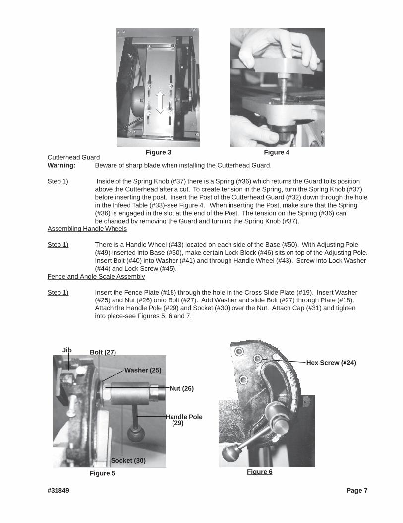
Cutterhead GuardWarning: Beware of sharp blade when installing the Cutterhead Guard.
Step 1) Inside of the Spring Knob (#37) there is a Spring (#36) which returns the Guard toits positionabove the Cutterhead after a cut. To create tension in the Spring, turn the Spring Knob (#37)before inserting the post. Insert the Post of the Cutterhead Guard (#32) down through the holein the Infeed Table (#33)-see Figure 4. When inserting the Post, make sure that the Spring(#36) is engaged in the slot at the end of the Post. The tension on the Spring (#36) canbe changed by removing the Guard and turning the Spring Knob (#37).
Assembling Handle Wheels
Step 1) There is a Handle Wheel (#43) located on each side of the Base (#50). With Adjusting Pole(#49) inserted into Base (#50), make certain Lock Block (#46) sits on top of the Adjusting Pole.Insert Bolt (#40) into Washer (#41) and through Handle Wheel (#43). Screw into Lock Washer(#44) and Lock Screw (#45).
Fence and Angle Scale Assembly
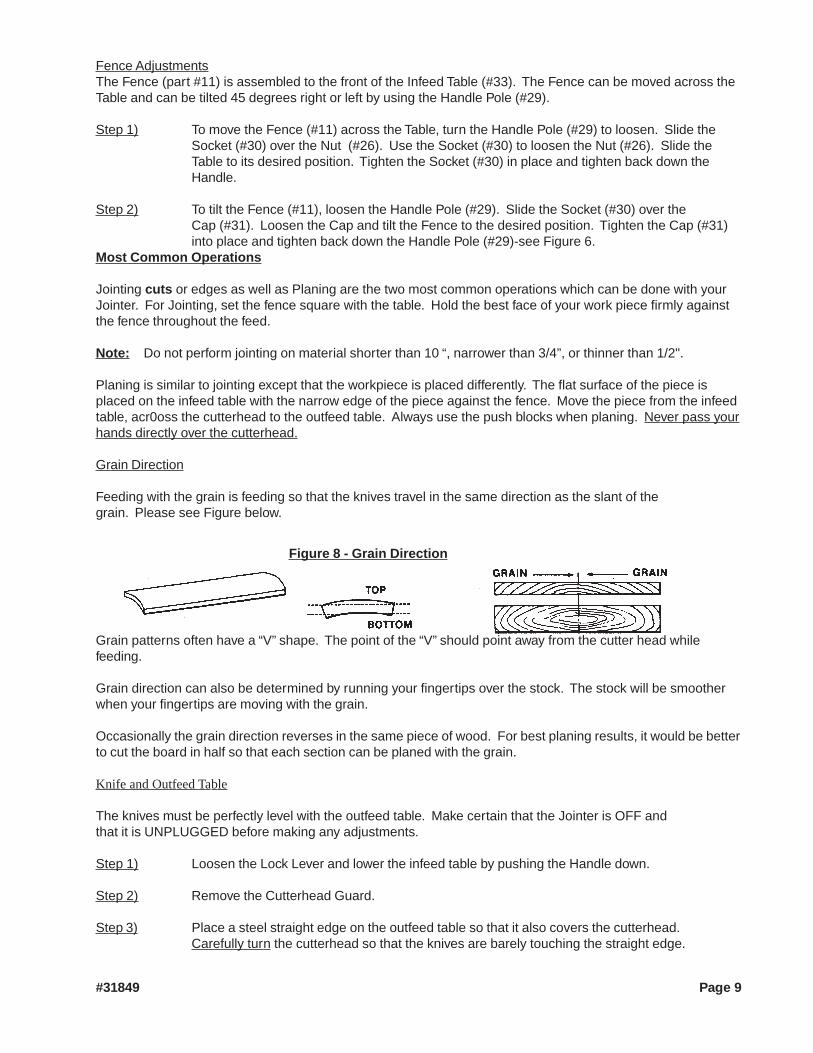
Step 1) Insert the Fence Plate (#18) through the hole in the Cross Slide Plate (#19). Insert Washer(#25) and Nut (#26) onto Bolt (#27). Add Washer and slide Bolt (#27) through Plate (#18).Attach the Handle Pole (#29) and Socket (#30) over the Nut. Attach Cap (#31) and tighteninto place-see Figures 5, 6 and 7.
Figure 3 Figure 4
Washer (25)
Nut (26)
Socket (30)
Bolt (27)
Figure 5
Jib
Hex Screw (#24)
Figure 6
Handle Pole(29)
#31849 Page 7

Step 2) Flip the square jib so that its end sits against the flat part of the Plate (18)-see Figure 7.
Step 3) Using an Allen Wrench, attach this assembly to the Fence (#11) with the three Hex Screws(#24)-see Figure 6.
Operation
When operating your Jointer, it will be helpful to refer to the Parts List and Assembly Diagram on the last pagesof this manual.
Never force the tool or attachment to do the work of a larger industrial tool. It is designed to do the job betterand more safely at the rate for which it was intended.
Use only wood boards.
Do not force feed your work through the machine. Allow the Jointer to feed at the designated rate of feed.
Note: This tool is specifically designed for the planing of lumber. Before working with any lumber,check for any foreign materials such as nails, screws, or hard impurities. Also check for looseknots in the wood. If not cleaned off these may cause damage to the blade or machine.
When feeding your lumber, use Push Blocks to feed the lumber, rather thanusing your hands.
Settings and Adjustments
Before adjustments are made, ensure that the machine is SWITCHED OFF AND UNPLUGGED. Also makesure all locking handles and securing screws are fully tightened when adjustments are complete.
Raising and Lowering Tables
Step 1) For both the Infeed Table (#33) and Out Feed Table (#1) loosen the Lock Screw (#45) nearestthe Handle Wheel (#43). Turn the Handle Wheel until the Table is set at the proper height.Once the table is set as desired, tighten down the Lock Screw (#56).
PlateJib
Figure 7
#31849 Page 8
Fence AdjustmentsThe Fence (part #11) is assembled to the front of the Infeed Table (#33). The Fence can be moved across theTable and can be tilted 45 degrees right or left by using the Handle Pole (#29).
Step 1) To move the Fence (#11) across the Table, turn the Handle Pole (#29) to loosen. Slide theSocket (#30) over the Nut (#26). Use the Socket (#30) to loosen the Nut (#26). Slide theTable to its desired position. Tighten the Socket (#30) in place and tighten back down theHandle.
Step 2) To tilt the Fence (#11), loosen the Handle Pole (#29). Slide the Socket (#30) over theCap (#31). Loosen the Cap and tilt the Fence to the desired position. Tighten the Cap (#31)into place and tighten back down the Handle Pole (#29)-see Figure 6.
Most Common Operations
Jointing cuts or edges as well as Planing are the two most common operations which can be done with yourJointer. For Jointing, set the fence square with the table. Hold the best face of your work piece firmly againstthe fence throughout the feed.
Note: Do not perform jointing on material shorter than 10 “, narrower than 3/4”, or thinner than 1/2".
Planing is similar to jointing except that the workpiece is placed differently. The flat surface of the piece isplaced on the infeed table with the narrow edge of the piece against the fence. Move the piece from the infeedtable, acr0oss the cutterhead to the outfeed table. Always use the push blocks when planing. Never pass yourhands directly over the cutterhead.
Grain Direction
Feeding with the grain is feeding so that the knives travel in the same direction as the slant of thegrain. Please see Figure below.
Grain patterns often have a “V” shape. The point of the “V” should point away from the cutter head whilefeeding.
Grain direction can also be determined by running your fingertips over the stock. The stock will be smootherwhen your fingertips are moving with the grain.
Occasionally the grain direction reverses in the same piece of wood. For best planing results, it would be betterto cut the board in half so that each section can be planed with the grain.
Knife and Outfeed Table
The knives must be perfectly level with the outfeed table. Make certain that the Jointer is OFF andthat it is UNPLUGGED before making any adjustments.
Step 1) Loosen the Lock Lever and lower the infeed table by pushing the Handle down.
Step 2) Remove the Cutterhead Guard.
Step 3) Place a steel straight edge on the outfeed table so that it also covers the cutterhead.Carefully turn the cutterhead so that the knives are barely touching the straight edge.
Figure 8 - Grain Direction
#31849 Page 9

Step 4) If the knife is not aligned at one or both sides, loosen Bolts (60) which hold the Knife Lock Bar(61). Use a knife setting gauge (not included) to make sure that the knife at each end of thecutter is the same height. Repeat for the next two (2) knives as is fitting. If the knives are setto low, this will result in a curve in your wood. If the knives are too high, it may result in agouged cut in your work piece.
Adjusting Table Gibs
“Gibs” are adjusted at the factory and should not need adjusting. Adjustments should be made by a qualifiedservice technician. If adjustment is required, please follow the steps laid out below after unplugging theelectrical connection.
Step 1) Loosen all the gib adjusting screws, making sure that the Table Lock Screw (#45) is loose.
Step 2) Retighten the gib screws beginning with the lowest first and moving to the top gib. Push upgently on the outside edge of the Table being adjusted.
Warning: Do not leave the screws too loose. It should take some effort to move the Table up or down.
Removing or Replacing Knives
Make certain that the Jointer is UNPLUGGED and OFF. Adjustments should be made my a qualified servicetechnician. Be extremely careful when handling the knives! Make certain that the Bars are free of dirt anddebris.
Step 1) Move the Fence (#11) to the rear of the Jointer and remove the Cutterhead Guard.
Step 2) With a wrench, loosen the four (4) Screws (#12) in each knife slot. Remove each Knife (#62)and the Knife Lock Bars (#61).
Step 3) Replace the Knives (#62) in the groove so that the rear edge of the bevel is 1/16” from thesurface of the Cutterhead.
Step 4) Slide the Lock Bar (#61) into place. Tighten down the Screws (#12) in each slot.
Warning! Knife edges are very sharp. Be very careful when moving knives. Refer to Operator SafetyInstructions at the beginning of this manual.
Step 5) The surface of the Cutterhead and the blade must be parallel, as well as the blade to the Bar.All three should be parallel to each other.
Step 6) Correct adjustment will ensure that the cutting edge of the knife extends out at.060" from the cutterhead diameter.
Step 7) Carefully turn the cutterhead, until its round side is showing on top. Place a .060" feelergauge on the cutterhead. With a straight edge on the rear table adjust the height of the reartable to .060".
#31849 Page 10REV 02/05

Step 8) Secure the rear table in position and remove the feeler gauge.
Step 9) Lower the infeed table and place a straight edge on the outfeed table so that itextends out over the cutterhead.
Step 10) Turn the cutterhead by hand until the knife is at its highest point at each end of the cutterhead.Using the wrench, turn the screw clockwise until the knife just touches the straight edge oneach end and at the center. Once the knife is fully adjusted, again tighten the four lockingscrews.
Sharpening the Knives
Step 1) Use a fine grade Carborundum stone. Cover the bottom portion of the stone withpaper. The top portion will touch the knife, and the paper will keep the stone fromscratching the table.
Step 2) Lay the stone on the infeed table. Lower the table and turn the cutterhead until the stone liesflat on the edge of the knife. Sharpen the beveled edge of the knife by sliding the stone backand forth across the table. Repeat for each additional knife.
Wiring the Jointer-On and OFF
Step 1) Insert the Switch Box through the hole in the Stand (#69).
Step 2) Insert the wires through the hole in the Switch Box-see Figure 9.
Step 3) The cord from the Motor (#29A-Stand Assembly) contains three (3) different colored wires;White, Green and Black. The White wire from the Motor (#29A) is attached to the wiring box onthe bottom lower left.
Step 4) The Black Wire from the Motor is attached to the box at the bottom right. The green from theMotor is attached to the ground.
Step 5) The Electrical Cord has three different colored wires; Green, White and Black.The white wire is to be attached to the box at the top left. The Black is to beattached to the top right. The green wire goes to the ground.
Step 6) The ground is the lower screw as shown in Figure 10. The lower screw is inserted through theJointer and is tightened into place by sliding on a Lock Washer and then a Nut. Do not tighteninto place until both green wires are attached to the ground-see Figure 10 and 12.
Outlet
Switch Box
Figure 9
GroundGreen Wires
White from Outlet
White from Motor
BlackFrom Cord
Black From Motor
Figure 10 Figure 11#31849 Page 11
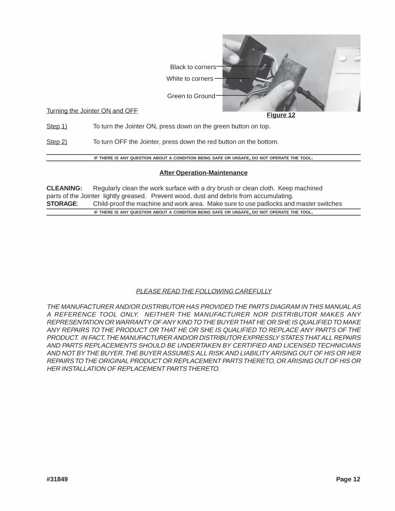
Turning the Jointer ON and OFF
Step 1) To turn the Jointer ON, press down on the green button on top.
Step 2) To turn OFF the Jointer, press down the red button on the bottom.
IF THERE IS ANY QUESTION ABOUT A CONDITION BEING SAFE OR UNSAFE, DO NOT OPERATE THE TOOL.
After Operation-Maintenance
CLEANING: Regularly clean the work surface with a dry brush or clean cloth. Keep machinedparts of the Jointer lightly greased. Prevent wood, dust and debris from accumulating.STORAGE: Child-proof the machine and work area. Make sure to use padlocks and master switches
IF THERE IS ANY QUESTION ABOUT A CONDITION BEING SAFE OR UNSAFE, DO NOT OPERATE THE TOOL.
Figure 12
Green to Ground
White to corners
Black to corners
#31849 Page 12
PLEASE READ THE FOLLOWING CAREFULLY
THE MANUFACTURER AND/OR DISTRIBUTOR HAS PROVIDED THE PARTS DIAGRAM IN THIS MANUAL ASA REFERENCE TOOL ONLY. NEITHER THE MANUFACTURER NOR DISTRIBUTOR MAKES ANYREPRESENTATION OR WARRANTY OF ANY KIND TO THE BUYER THAT HE OR SHE IS QUALIFIED TO MAKEANY REPAIRS TO THE PRODUCT OR THAT HE OR SHE IS QUALIFIED TO REPLACE ANY PARTS OF THEPRODUCT. IN FACT, THE MANUFACTURER AND/OR DISTRIBUTOR EXPRESSLY STATES THAT ALL REPAIRSAND PARTS REPLACEMENTS SHOULD BE UNDERTAKEN BY CERTIFIED AND LICENSED TECHNICIANSAND NOT BY THE BUYER. THE BUYER ASSUMES ALL RISK AND LIABILITY ARISING OUT OF HIS OR HERREPAIRS TO THE ORIGINAL PRODUCT OR REPLACEMENT PARTS THERETO, OR ARISING OUT OF HIS ORHER INSTALLATION OF REPLACEMENT PARTS THERETO.

Unpacking
UNPACK AND CHECK CONTENTSWhen unpacking your Jointer with Stand check to make sure the following parts are included. If any parts aremissing or broken, please call HARBOR FREIGHT TOOLS at 1-800-444-3353.
Parts List - Stand Assembly
Part # Description Quantity Part # Description Quantity1A Roof 1 17A Head Square Root Screw 322A Upper Link Plate 1 18A Crossbeam Plate 13A Reinforce Plate 1 19A Side Link Plate 24A Upright Plate 1 20A Chassis 45A Bolt M8 X25 4 21A Lock Washer 46A Nut 50 22A Bolt 17A Washer 50 23A Right Tapping Fender 68A Right Protect Plate 1 24A Lock Plate 19A Nut 2 25A Tapping Plate 110A Screw M4 x 25 2 26A Left Protecting Plate 111A Screw M5 X 8 1 27A Left Tapping Fender 112A Washer 1 28A Motor Pulley 113A Nut 1 29A Motor 114A Lock clip 1 30A Rear Side Plate 115A Cable 1 31A Button head Cap Screw 1016A Front Side Plate 1
#31849 Page 13
Note: Some parts listed and shown (pages 13 through 16) are for illustrationpurposes only and are not available individually as replacement parts.

Parts List - Jointer Assembly
Part # Description Quantity Part # Description Quantity1 Outfeed Table 1 36 Spring 12 Bearing Housing 1 37 Spring Knob 13 Ball bearing 1 38 Retainer 14 Cutter Head Assembly 1 39 Recessed Screw 35 Key 1 40 Belt 26 Ball Bearing 1 41 Washer 27 Bearing Housing 1 42 Pin 28 Set Screw M6 X 12 2 43 Handle Wheel 29 Cutter Head Pulley 1 44 Lock Washer 210 Belt 1 45 Lock Screw 211 Fence 1 46 Lock Block 212 Set Screw M6 X 10 1 47 Flat Washer 413 Roll Pin 1 48 Hex Screw 414 Set Screw M 6 X 10 1 49 Adjusting Pole 215 Set Screw M6 X 10 1 50 Base 116 Bolt 6 X 40 3 51 Nut 217 Nut 3 52 Lock Washer 218 Plate 1 53 Fault Washer 219 Cross Slide Plate 1 54 Screw 220 Stop Block 1 55 Depth Scale 121 Pointer Rod 1 56 Lock Screw 222 Fence Segment 1 57 Bolt 423 Tilt Angle Seat 1 58 Nut 424 Hex Screw 3 59 Gib 225 Washer 3 60 Bolt 1226 Nut 1 61 Knife Lock Bar 327 Bolt 1 62 Knives 328 Handle Ball 1 63 Recessed Screw M 8 X 12 229 Handle Pole 1 64 Belt Cover 130 Socket 1 65 Flat Washer 231 Cap 1 66 Nut 232 Cutter Guard 1 67 Flat Washer 333 Infeed Table 1 68 Bolt 334 Retainer Washer 1 69 Stand (See Stand Assy.) 135 Depth Scale 1
#31849 Page 14REV 10/02

Stand Assembly Diagram
Each of the Part Numbers below correspond to the Stand Assembly and has the suffix “A” - see Parts List onPage 13.
#31849 Page 15
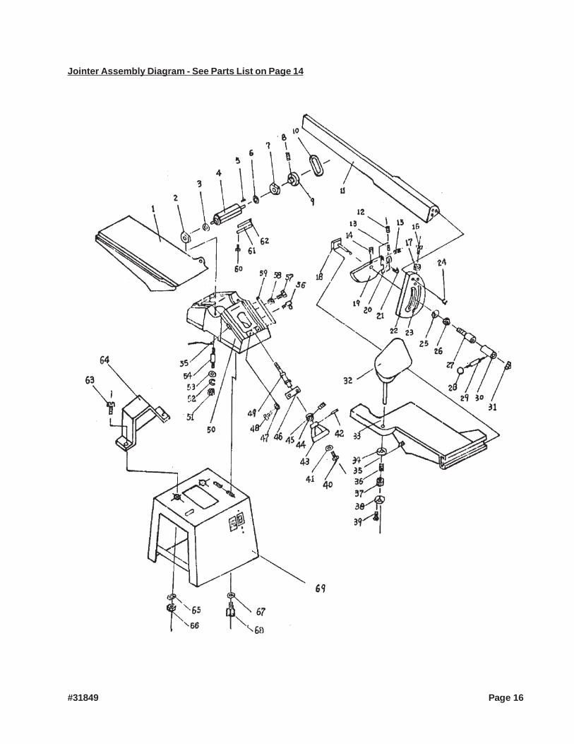
Jointer Assembly Diagram - See Parts List on Page 14
#31849 Page 16
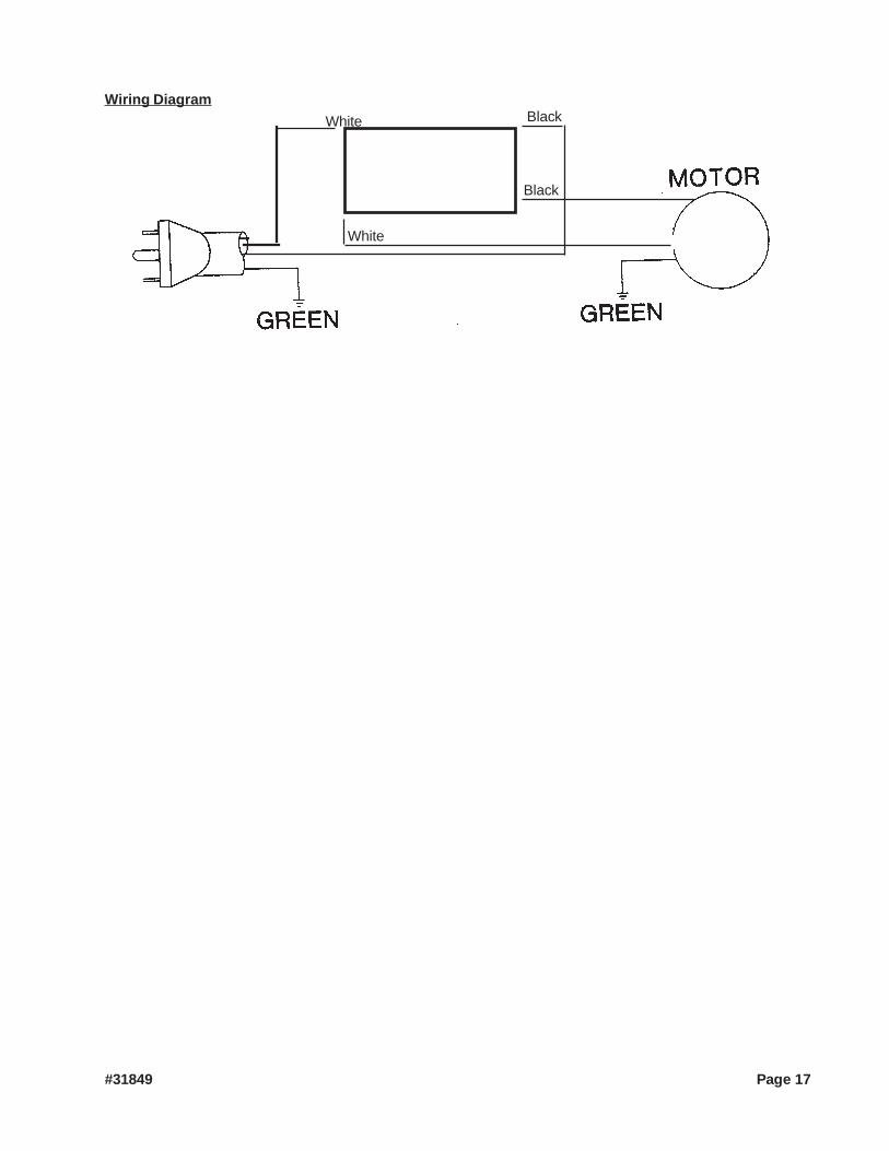
White
White
Black
Black
Wiring Diagram
#31849 Page 17