Embed Size (px)
Citation preview
Optoelektronische Sensoren /
Photoelectric Sensors
Balluff GmbH
Schurwaldstraße 9 73765 Neuhausen a.d.F.
Deutschland Tel. +49 7158 173-0 Fax +49 7158 5010
[email protected] www.balluff.com
PC Tool
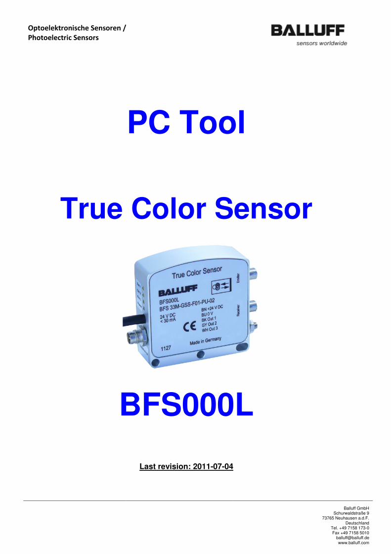
True Color Sensor
BFS000L
Last revision: 2011-07-04

Optoelektronische Sensoren /
Photoelectric Sensors
Balluff GmbH
Schurwaldstraße 9 73765 Neuhausen a.d.F.
Deutschland Tel. +49 7158 173-0 Fax +49 7158 5010
[email protected] www.balluff.com
Table of content
Chapters:
1. General Advice ............................................................................................................ 3
2. Safety and warning instructions ................................................................................... 4
3. True Color Sensor Tool ................................................................................................ 5
3.1.1. The group Communication .............................................................................. 5
3.1.2. The group Gain ............................................................................................... 6
3.1.3. The group Averaging Cycles ........................................................................... 7
3.1.4. The group Compensate Environment .............................................................. 7
3.1.5. The bar line displays X, Y, Z and the ‘Normalize’ function .............................. 8
3.1.6. The group Work Mode ..................................................................................... 8
3.1.7. The group Products ......................................................................................... 9
3.1.8. The group Logging ........................................................................................ 10
3.1.9. The group State ............................................................................................. 11
3.1.10. Other operational and display elements ..................................................... 12
Figures:
Figure 1 Dialog PC Tool ...................................................................................................... 5
Tables:
Table 1 : Correlation of product number to digital outputs................................................. 11

Optoelektronische Sensoren /
Photoelectric Sensors
Balluff GmbH
Schurwaldstraße 9 73765 Neuhausen a.d.F.
Deutschland Tel. +49 7158 173-0 Fax +49 7158 5010
[email protected] www.balluff.com
1. General Advice
The True Color Sensor is generally not conceived for the use as a safety critical component in machines and assets and in particular not for the utilization in the medical sector. Please note that the use in these sectors is inadmissible.
Please observe the required safety precautions when handling with ESD-sensitive components (EN
61340-5-1, EN 61340-5-2)!
The module may only be installed or replaced by skilled personnel!
The internal luminous source of white light is very powerful. Please beware of looking directly into
the aperture of the light source at the module or in the connected light guides, respectively.
„This sensor is optimized for the detection of objects. An absolute color measurement
is not possible.“
When entering numerical values with a decimal place, only a point is accepted as separator
(e.g. 94.4).
The sensor allows for the detection of objects for short and longer distances. The minimum and maximum distances can only be defined insufficiently, since this depends on different conditions even for given optics. These can be compensated again within wide limits by the adjustable sensitivity. For the angle one can meet a general statement. The optic should not be aligned perpendicular to the product. A reference value for the angle is 22.5° (for coaxial light guide). „The sensor achieves its full accuracy after a turn-on time of 20 minutes under
constant side conditions. The duration of the warm-up period depends on the
environmental conditions.“

Optoelektronische Sensoren /
Photoelectric Sensors
Balluff GmbH
Schurwaldstraße 9 73765 Neuhausen a.d.F.
Deutschland Tel. +49 7158 173-0 Fax +49 7158 5010
[email protected] www.balluff.com
2. Safety and warning instructions
These photoelectric sensors may not be used in applications where personal safety depends on proper
function of the devices (not safety designed per EU machine guideline). Read these operating instructions
carefully before putting the device into service.
Exempt Group according to IEC 62471:2006-07.
DO NOT LOCK INTO THE LIGHT BEAM!
Danger of glare and irritation!
The sensor must be installed so that no direct looking into the light source is possible even during
operation.

Optoelektronische Sensoren /
Photoelectric Sensors
Balluff GmbH
Schurwaldstraße 9 73765 Neuhausen a.d.F.
Deutschland Tel. +49 7158 173-0 Fax +49 7158 5010
[email protected] www.balluff.com
3. True Color Sensor Tool
The BFS33M PC Tool serves for the commissioning and parameterization of the True Color Sensor. The
picture shown below displays the main dialog of the tool after starting.
Figure 1 Dialog PC Tool
Information: When entering numerical values with a decimal place, only a point is accepted as
separator (e.g. 94.4).
3.1.1. The group Communication Before a communication to the sensor can be established the serial interface of the sensor must be
connected to the PC. At the edit field ‘COM Port’ the number of the serial interface must be entered and
the button ‘Connect’ must be pressed. The tool will try to establish a communication to the sensor. If the
connection has been established successfully a dialog is displayed that is showing the actual serial number
and the firmware version of the connected sensor.

Optoelektronische Sensoren /
Photoelectric Sensors
Balluff GmbH
Schurwaldstraße 9 73765 Neuhausen a.d.F.
Deutschland Tel. +49 7158 173-0 Fax +49 7158 5010
[email protected] www.balluff.com
Afterwards all controls will be updated according to the actual settings. In addition the serial number of the
connected sensor will be shown at the field ‘Serial Number’. Later on the serial number will be used e.g.
when logging measurement values, to give the log file a unique name.
In general the CIEL Color Sensor works in a ‘free running’ mode. Measurement values from the sensor will
be read continuously with a frequency of about 3Hz and displayed at the PC Tool.
The text on the button ‘Connect’ will change to ‘Disconnect’ after successful connection to the sensor.
When pressing the button once again the communication is suspended and the text on the button will
change to ‘Connect’. All activities at the PC tool regarding the sensor will be interrupted in that case.
The checkbox ‘Dialog Language’ is used to select the language that should be used for displaying text
within the main dialog and additional dialog windows. The checkbox contains the available languages for
those language specific text files have been found at the program directory when starting the tool. Per
default the language ‘English’ is always available even if there are no language specific files at the program
directory. After selecting a new language at the checkbox all displayed text inside of the tool will change
immediately to the corresponding texts from the language specific file.
When starting the PC tool it scans for the file ‘LastSettings.txt’ at the program directory. Inside of this file
the last settings for ‘COM Port’ and ‘Dialog Language’ are saved. If the file is available at the program
directory when starting the PC tool the parameters will be used as default values for ‘COM Port’ and ‘Dialog
Language’. When closing the tool the actual settings of those settings will be saved to the file
‘LastSettings.txt’.
3.1.2. The group Gain The amplification of the sensor can be adjusted manually via the combo box ‚Gain‘. For an optimum setting
of the gain value the brightest product must be presented in front of the light guide of the sensor. With
that the gain should be changed to the highest value were no ‘Overload’ of the sensor signal occurs. The
‘Overload’ of the sensor signal is represented by the virtual LED ‘Signal OK’ shown below the combo box. As
long as no ‘Overload’ is present the color of the LED is green. In case of an Overload the color of the LED
changes to red.
As reference point for the brightest product the display bar of the Intensity (Y value) can be used.

Optoelektronische Sensoren /
Photoelectric Sensors
Balluff GmbH
Schurwaldstraße 9 73765 Neuhausen a.d.F.
Deutschland Tel. +49 7158 173-0 Fax +49 7158 5010
[email protected] www.balluff.com
When activating the checkbox ‘Enable Auto-Gain’ the gain will be changed automatically for each product.
In principle the use of the automatic gain setting is recommended. Exceptions only apply for applications
that need the maximum processing speed of the sensor and where large changes of the intensity within a
very short time occur at the same time. Apart from that the automatic gain setting needs no additional
calculation time as long as no overload occurs from one measurement cycle to another (on the basis of a
stabilized measuring condition).
3.1.3. The group Averaging Cycles The checkbox ‘Averaging Cycles’ serves for the parameterization of the averaging that should be considered
during measuring the values with the sensor. The values at the checkbox are selected in such a way that for
each next step the noise of the sensor signal is cut to the half. At the same time thereby however the signal
delay rises itself whereby the time for a stable signal output is extended. Finally the best result for the
setting of the average values must result from the compromise between the available process time and the
necessary accuracy.
3.1.4. The group Compensate Environment Die function ‘Compensate Environment’ can be used for application where the sensor could receive
‘scattered light’ from its own light source. That means reflected light from the light source that is not
influenced by the product itself directly. A good example for that is the using of an optic where sender and
receiver will use the same optical path. The ‘scattering’ of the light inside of the optic caused by the lenses
and the housing of the optic leads to it that the receiver will ‘receive’ more or less light reflected from the
own light source even if the optic ‘looks’ into the empty. This part of ‘scattered light’ leads to a kind of
offset that makes all colors more achromatic. In addition one can easily present that the information signal
of the actual product in relation the scattered light becomes worst the further away the optic is arranged
from the product.
The Environment Compensation can be uniquely used now to compensate those unwanted effects. The
compensation is permanently stored on the sensor. It must be repeated only then if e.g. optical
components or light guides were exchanged.
The Environment Compensation is started by pressing the button ‘Compensate’. It must be observed that
the sensor ‘looks’ into the empty and no product is in front of the optic or the light guide while processing
the Environment Compensation. The tool automatically executes the necessary steps for the compensation
and saves the data on the sensor.
The Environment Compensation becomes however only active by selection of the box ‘Enable
Compensation’. The sensor uses the last saved compensation values if ‘Enable Compensation’ has been
activated. If the compensation is not enabled the sensor will not use the saved compensation data. With
each change of the status of the box ‘Enable Compensation’ the actual status for the release of the
compensation will be saved on the sensor.

Optoelektronische Sensoren /
Photoelectric Sensors
Balluff GmbH
Schurwaldstraße 9 73765 Neuhausen a.d.F.
Deutschland Tel. +49 7158 173-0 Fax +49 7158 5010
[email protected] www.balluff.com
3.1.5. The bar line displays X, Y, Z and the ‘Normalize’ function The bar line displays shown here present the actual measured sensor values as Tristimulus values. The
Tristimulus values build the base for the conversion of the actual measurement values to the CIELab color
space. For the (simplified) calculation a normalized Tristimulus input range from 0…100 will be assumed.
However the internal range of the values depends on many factors. In practice considerable effects
depending on the used light guide, optics and the measuring distance are to be called.
The Tristimulus values will be used for the evaluation of the test results only in an indirect way – there are
no limits or tolerances that depend on the Tristimulus values. Besides from that these values are strictly
linear. This does not apply on the CIELab values. For that reason the Tristimulus values are better suitable
to e.g. to derive the degree of saturation of the sensor.
For the reason that the calculation to the CIELab color space must work all the time and in addition to
adapt to different measuring conditions and applications, usually at first after mounting of all determining
components a so called normalization must be established. Target of the normalization is to enforce a
defined intensity result for a defined measuring condition.
Typically white balance cards with well known reference values will be used for that. Such an absolute
calibration is only necessary if the CIELab measurement values should match measurement values from
other devices as exact as possible. Often such references could not be used because e.g. the contour of the
product does not permit the mounting of such a reference. For that reason the normalization can be set to
‘arbitrary’ target values with the help of the PC tool. That makes it possible e.g. to create a ‘Golden Product’
where an intensity value is assumed that can be estimated from a grey scale. A ‘100% White’ would have a
target value of 100, a 50% white (a light grey) would have a target value of 50.For a standard non-glossy
paper a value of around 90 can be assumed.
After defining the reference a stable measuring condition for the reference must be set up. After that the
intended Tristimulus-Y intensity value must be entered at the field ‘Target Y’ and the button ‘Normalize’
must be pressed afterwards. After a few seconds the normalization will be finished. If the shown
Tristimulus Y-Channel value is now identical to the intended value the normalization was successful.
Note: In contrast to most other parameters the normalization is automatically permanently saved on the
sensor. In addition we recommend using higher values for the averaging cycles for the normalization
independent from the setting for the averaging cycles used later on.
After a successful normalization the product parameters can be determined.
3.1.6. The group Work Mode The group offers the possibility for selecting between the work modes ‘Best Fit’ and ‘Precise’. Both modes
will be described in the following. When selecting a work mode that mode is immediately activated on the
sensor but the selection will not be saved permanently on the sensor.

Optoelektronische Sensoren /
Photoelectric Sensors
Balluff GmbH
Schurwaldstraße 9 73765 Neuhausen a.d.F.
Deutschland Tel. +49 7158 173-0 Fax +49 7158 5010
[email protected] www.balluff.com
In ‘Best Fit’ mode the sensor does not consider any defined product tolerances. The sensor always
internally processes the parameters of all active products and as a results returns the product number to
which the actual values best fit. For the determination of the best fitting product the Delta-E between the
actual measured values and the target values for any saved product are calculated. If more than one of the
saved products shows the exact same variation to the actual values, then the lowest of those product
numbers is returned. In this mode always one product will be detected as best fitting product,
independent from the given product parameters!
The work mode ‘Best Fit’ is best suited for the selection of objects out of several (known products). In an
automation process it can e.g. be tested if an object with the correct color is fed in to the process, without
checking if the exact color shade is met. Thus this mode is suitable also very well for sorting tasks.
In ‘Precise’ mode a specific product number as test result is only given if the actual values of the sensor lie
with the given tolerances for that product. If the actual values are inside of the tolerances of multiple
products then no clearly correlation to a product is possible. In that case none of the digital outputs (OUT
1...3) will be set. If the actual values are lying outside of the tolerances of any saved product, no product
number is detected and the digital outputs (OUT 1…3) are reset. The corresponding digital outputs are only
set if the actual values are lying inside the tolerances of exactly one product. The tolerances the products
are given with the product parameter ‘Delta-E’ (see chapter 3.1.7).
The ‘Precise’ mode is best suited e.g. for quality inspection of test objects, because here the tolerances for
color and intensity must fit in order to detect on object of that kind.
3.1.7. The group Products The dialog elements of this group serve for the parameterization of the product parameters as well as for
the indication of the entered product parameters.
The parameter can be entered for the corresponding products and for the product ‘Background’. The
particular product is selected via the corresponding text at the combo box ‘Product No.’. The edit fields
‘Target CIELab-L’, ‘Target CIELab-a’ and ‘Target CIELab-b’ show the last saved CIELab values for the selected
product. The field ‘Actual delta-E’ displays the ‘color’ error of the actual measured value of the sensor
regarding the saved measurement value for that product. The parameter ‘Target delta-E’ does have only an
impact for the ‘Precise’ work mode (see chapter 3.1.6) and can be edited only if that mode is active. The
parameter serves for setting a tolerance values (Delta-E) that must be met for that product.
The button ‘Set Product Parameters’ is used for transferring the product parameters to the sensor. The
product parameters then will be immediately activated for the corresponding product. The parameter will

Optoelektronische Sensoren /
Photoelectric Sensors
Balluff GmbH
Schurwaldstraße 9 73765 Neuhausen a.d.F.
Deutschland Tel. +49 7158 173-0 Fax +49 7158 5010
[email protected] www.balluff.com
not be permanently saved on the sensor. That means if the sensor is switched off the changes will be lost.
For saving the parameters permanently on the sensor the button ‘Save Remanent’ must be pressed.
Information: „Set Product Parameters“ is necessary only if CIELab target values are to be entered
manually. If the actual product can be used for ‚teaching‘ the activation of „Use Actual Color As
Product Target“ is sufficient. For the PRECISE Mode additional tolerances must be given, which can
only be entered manually. In that case „Set Product Parameters“ must be used.
The parameters can be changed by manually entering CIELab values at the edit fields or by using the actual
values of the sensor. For using the actual sensor values as product parameters for the selected product the
button ‘Use Actual Color As Product Target’ must be pressed. With that the actual sensor values will be
transferred to the edit fields and the product parameters will be saved immediately to the sensor. The
product parameter will not be saved permanently on the sensor.
During the test for the correlation of the actual measured values regarding the saved product parameters
and determination of the product that fits the best, only those products are considered were the
parameter ‘Enable Product’ has been active when saving the product parameters.
The special product ‘Background’ is used for setting up the product parameters for the background. If the
product ‘Background’ has been determined as the product that ‘best fits’ the actual measurement values,
none of the digital outputs (Out 1…3) of the sensor will be set. In ‘Best Fit’ work mode this product e.g. can
be used to detect that ‘no’ object is present in front of the sensor. In ‘Precise’ mode it e.g. can be used to
define ‘areas’ within the actual values of an object should not lie in any case.
3.1.8. The group Logging The logging of the actual measurement values of the sensor can be started by pressing the button ‘Start
Logging’. The text on the button will change to ‘Stop Logging’ and the log function will be active. By
pressing the button once again the log function is stopped and the text on the button will change back to
‘Start Logging’.
When starting the log function the selection of the mode for the log function (‘Continuous’ or ‘Single’) is
recognized. If mode ‘Continuous’ is active a new line with the actual measurement values is added to the
log file each time the interval time given with parameter ‘Interval’ expires. If mode ‘Single’ is active a new
line with the actual measurement values is added to the log file each time the button ‘Single Shot’ is
pressed. The button is enabled only if the mode ‘Single’ is active. The selection between the modes is
disabled while the log function has been started.
With each start of the log function a new log file is created whose filename among others is build from the
actual date and time and the serial number of the connected sensor. The log file at first contains multiple
header lines with the actual setup product parameters. Whereupon followed by new lines with the actual
sensor values updated periodically (for mode ‘Continuous’) or when the button ‘Single Shot’ is pressed (for
mode ‘Single’). The log files will be saved in the so called CSV format. With that it is possible to use the log
files with e.g. Microsoft Excel for further processing.

Optoelektronische Sensoren /
Photoelectric Sensors
Balluff GmbH
Schurwaldstraße 9 73765 Neuhausen a.d.F.
Deutschland Tel. +49 7158 173-0 Fax +49 7158 5010
[email protected] www.balluff.com
3.1.9. The group State The virtual LEDs (Out 1...3) correspond to the status of the digital outputs of the sensor. These outputs are
always set regarding the product that is actually detected as ‘best fit’ product from the sensor. For the test
only products will be considered that has been marked as active during the parameterization of the product
(Parameter ‘Enable Product’).
The actual product number of the product detected as ‘best fit’ product from the sensor is shown at the
field ‘Output Product’. This field represents thereby also the decoded output combination.
The correlation of the bit coded product number to the corresponding digital outputs (Out 1...3) can be
taken from the following table.
Product No. Bit Code Out 3 Out 2 Out 1
Background 0000 0 0 0
1 0001 0 0 1
2 0010 0 1 0
3 0011 0 1 1
4 0100 1 0 0
5 0101 1 0 1
6 0110 1 1 0
7 0111 1 1 1
Table 1 : Correlation of product number to digital outputs
For applications were a direct assignment of a detected product number to a specific digital output is
desired the products 1, 2 and 4 can be used, because for those products only one digital output (Out 1…3)
is active at a time. In that case all other products must be marked as inactive (Parameter ‘Enable Product’
not active).
If the product ‘Background’ has been determined as the product that ‘best fits’ the actual measurement
values the virtual LED ‘Background’ will be active and all other LEDs (Out 1…3) will be off. In that case all
digital outputs of the sensor (Out 1…3) will be reset.

Optoelektronische Sensoren /
Photoelectric Sensors
Balluff GmbH
Schurwaldstraße 9 73765 Neuhausen a.d.F.
Deutschland Tel. +49 7158 173-0 Fax +49 7158 5010
[email protected] www.balluff.com
3.1.10. Other operational and display elements The diagram shows the actual measurement values from the sensor as CIELab values. The CIELab-a and the
CIELab-b value will be displayed as a cross inside of the diagram. The CIELab-L value is shown at the bar line
display below the diagram. In addition the actual CIELab value are displayed as numeric values below the
bar line display.
Attention! After changing the gain, the Work Mode, the product parameters or the averaging cycles the
values are NOT permanently saved on the sensor. If the sensor is switched off then the changed settings
will be lost. For the permanent saving of the values on the sensor the button ‘Save Permanent’ must be
pressed. With that the settings will be saved preserved if the sensor is switched off.
By clicking the button ‚Exit‘, the program is terminated.