Embed Size (px)
Citation preview
BTL7-S510(B)-...
Micropulse Configuration Tool – Manual
english
+USB-Configurable

www.balluff.com
3englishwww.balluff.com
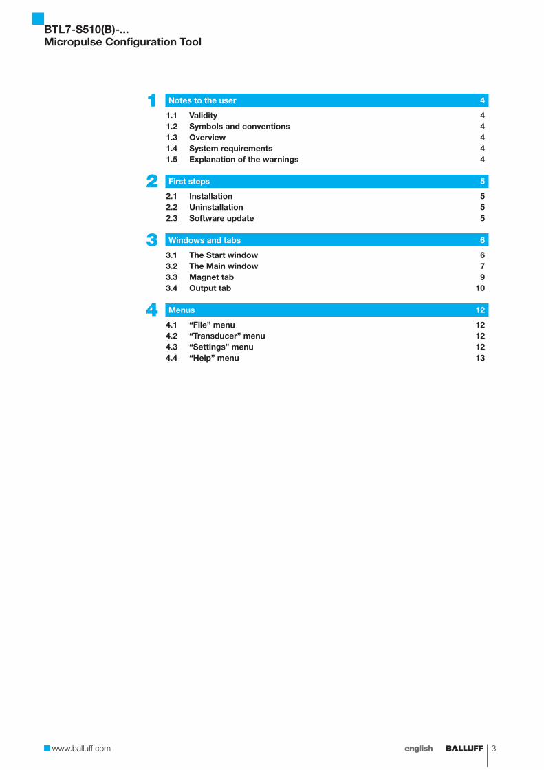
1 Notes to the user 4
1.1 Validity 41.2 Symbols and conventions 41.3 Overview 41.4 System requirements 41.5 Explanation of the warnings 4
2 First steps 5
2.1 Installation 52.2 Uninstallation 52.3 Software update 5
3 Windows and tabs 6
3.1 The Start window 63.2 The Main window 73.3 Magnet tab 93.4 Output tab 10
4 Menus 12
4.1 “File” menu 124.2 “Transducer” menu 124.3 “Settings” menu 124.4 “Help” menu 13
BTL7-S510(B)-...Micropulse Configuration Tool
4 english
1.1 Validity
This guide describes installation and operation of the configuration software for the Micropulse Transducer BTL7-S510(B)-... (BTL7 USB-configurable).
The illustrations in the manual are for the B style, but the software can be used to display another style, depending on which transducer is connected. Depending on the style, windows or menu elements may also be hidden if the connected transducer does not support the respective functions.
1.2 Symbols and conventions
Action instructions are indicated by a preceding triangle. The result of an action is indicated by an arrow.
► Action instruction 1 ⇒ Action result
Action sequences are numbered consecutively:
1. Action instruction 1
2. Action instruction 2
Keys are set in angle brackets, e.g. “confirm by pressing <Enter>”.
Key combinations are buttons which are pressed simultaneously. These are joined by a plus sign, e.g. <Ctrl> + <O>.
Buttons are written in small caps, e.g. Update transdUcer.
Menu commands are joined with a greater-than sign, e.g. “Settings > Options” stands for the menu command “Options” from the “Settings” menu.
Note, tipThis symbol indicates general notes.
1.3 Overview
The Micropulse Configuration Tool allows Balluff transducers type BTL7-S510(B)-... to be quickly and simply configured. The results of the configuration are displayed online.
The most significant features are: – Online display of the current position of the magnet – Graphical support for setting the functions and curves – Display of information about the connected transducer – Selectable number formats and units for display – Resetting to factory settings is possible – Demo mode without having transducer connected
1.4 System requirements
Installation requires administrator rights on the PC.
– Standard PC – Windows 2000/XP/Vista/7 – Screen resolution at least 1024 × 768 pixels – 10 MB available hard disk space – USB interface – Java Runtime Environment (JRE) version 1.4.2 or
higher installed (download at http://java.com/getjava)
With 64-bit operating systems, the 32-bit Java version must be installed.
1.5 Explanation of the warnings
Always observe the warnings in these instructions and the measures described to avoid hazards.
The warnings used here contain various signal words and are structured as follows:
SIGNAL WORDHazard type and sourceConsequences if not complied with
► Measures to avoid hazards
The individual signal words mean:
DANGERThe general warning symbol in conjunction with the signal word DANGER identifies a hazard which, if not avoided, will certainly result in death or serious injury.
1 Notes to the user
BTL7-S510(B)-...Micropulse Configuration Tool
5englishwww.balluff.com
2.1 Installation
2.1.1 Installing the Configuration Tool on the PC
Installation is done using an Installation Wizard which guides you through the individual steps.
The USB communication box should not be connected during installation. It is not set up until the Configuration Tool is first started.
1. Make sure that the computer fulfills the system requirements.
2. Double-click on “ConfigTool_Setup_Vx_xx_xxx.msi“ ⇒ The Installation Wizard starts. Continue with next. ⇒ The license agreement is displayed. The next step
can only be carried out if the license agreement has been accepted.
3. Accept license agreement and click on next. ⇒ The target directory is displayed. ⇒ Use Browse to select a different target directory.
4. Click on next and then on Install. ⇒ The software is installed in the selected target
directory and entered in the Windows Start menu. A link is shown on the desktop.
⇒ When this procedure is complete, the last page of the Installation Wizard is displayed. The checkbox “Launch Micropulse Configuration Tool” is activated.
5. Click on FInIsh. ⇒ Installation is complete, the Configuration Tool is
started.
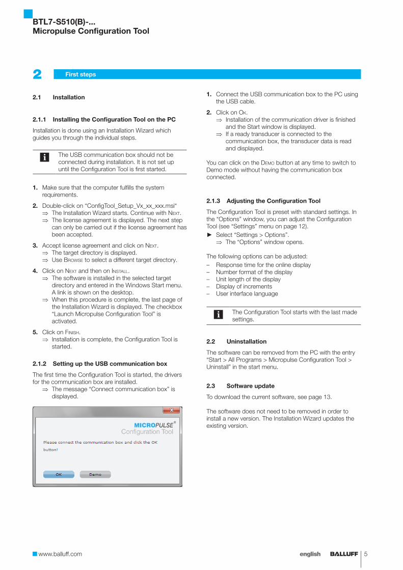
2.1.2 Setting up the USB communication box
The first time the Configuration Tool is started, the drivers for the communication box are installed.
⇒ The message “Connect communication box” is displayed.
1. Connect the USB communication box to the PC using the USB cable.
2. Click on ok. ⇒ Installation of the communication driver is finished
and the Start window is displayed. ⇒ If a ready transducer is connected to the
communication box, the transducer data is read and displayed.
You can click on the demo button at any time to switch to Demo mode without having the communication box connected.
2.1.3 Adjusting the Configuration Tool
The Configuration Tool is preset with standard settings. In the “Options” window, you can adjust the Configuration Tool (see “Settings” menu on page 12).
► Select “Settings > Options”. ⇒ The “Options” window opens.
The following options can be adjusted: – Response time for the online display – Number format of the display – Unit length of the display – Display of increments – User interface language
The Configuration Tool starts with the last made settings.
2.2 Uninstallation
The software can be removed from the PC with the entry “Start > All Programs > Micropulse Configuration Tool > Uninstall” in the start menu.
2.3 Software update
To download the current software, see page 13.
The software does not need to be removed in order to install a new version. The Installation Wizard updates the existing version.
2 First steps
BTL7-S510(B)-...Micropulse Configuration Tool

6 english
3.1 The Start window
3.1.1 Establish a connection
When starting, the Configuration Tool establishes the connection to the communication box and to the connected transducer. The data and transducer configuration are read and displayed in the main window.
The individual steps are shown in the Start window: – Connecting... Connection to the communication box
is established. – Opening... Connection to the transducer is
established. – Reading... Transducer data is read.
If the action can be successfully completed, the main window is displayed.
3.1.2 A connection cannot be made
If no connection to the communication box or to the transducer can be established, this message will appear on the start screen and the main window is not shown.
► Check the USB connection, unplug and plug in the cable on the PC, if necessary.
⇒ The Configuration Tool attempts again to establish the connection.
► Check connection between the transducer and the communication box, reconnect if necessary.
⇒ The Configuration Tool attempts again to contact the transducer.
► Switch to the Demo version. ⇒ A self-running demo is started. A transducer does
not need to be connected. ► Quit program (exIt).
⇒ The Configuration Tool is ended.
Please contact our service center if you still cannot establish a connection.
3 Windows and tabs
BTL7-S510(B)-...Micropulse Configuration Tool
7englishwww.balluff.com
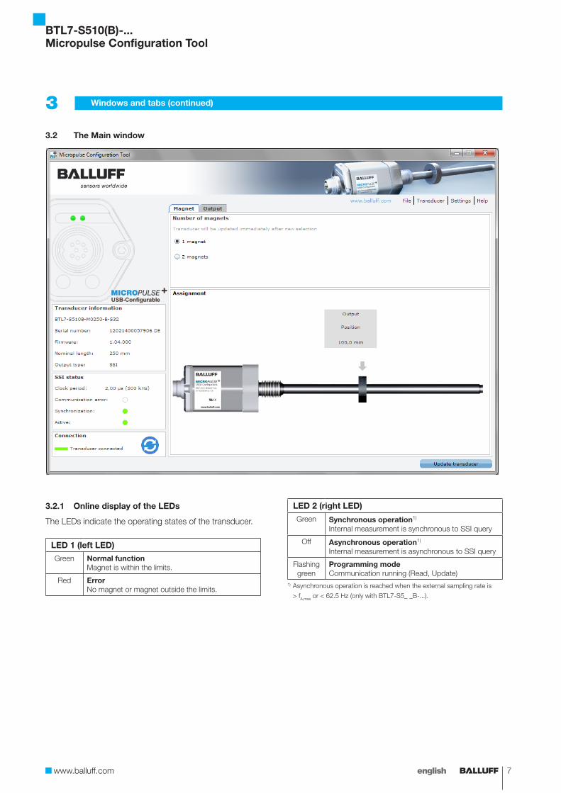
3.2 The Main window
3.2.1 Online display of the LEDs
The LEDs indicate the operating states of the transducer.
LED 1 (left LED)
Green Normal functionMagnet is within the limits.
Red ErrorNo magnet or magnet outside the limits.
LED 2 (right LED)
Green Synchronous operation1)
Internal measurement is synchronous to SSI query
Off Asynchronous operation1)
Internal measurement is asynchronous to SSI query
Flashing green
Programming modeCommunication running (Read, Update)
1) Asynchronous operation is reached when the external sampling rate is
> fA,max or < 62.5 Hz (only with BTL7-S5_ _B-...).
3 Windows and tabs (continued)
BTL7-S510(B)-...Micropulse Configuration Tool
8 english
3.2.2 Transducer information
The following transducer information is displayed: – Type – Serial number – Firmware version – Nominal length of the connected transducer – Output: SSI
3.2.3 SSI status
Clock periodE.g. 2.00 µs (500 kHz)
Display of the SSI clock period TCLK or SSI clock frequency fCLK
Communication error
If an SSI communication error (To or Tm-Event) has occurred
Synchronization
If synchronous operation is active in the transducer
Active
If the current position value has been queried via the SSI interface
3.2.4 Connection
This symbol is displayed when the communication box is active.
Transducer is connected.
Transducer is not connected.
3.2.5 Menu bar
The menu bar contains the menu commands. The menu commands are described in Section 4 “Menus” starting on page 12.
3.2.6 Update transducer
Changed values for a configuration are displayed in the Configuration Tool by means of blue numbers and letters and the Update transdUcer button is active.
Clicking on Update transdUcer sends the information to the transducer. Transmission takes a certain amount of time, since all the parameters are sent.
The Update transdUcer button is only active if there are changed settings pending.
3.2.7 Tabs
Settings are made on the tabs.
Magnet: – Select number of magnets. – Online display of the configuration.
Output: function, number of bits, coding, upper/lower limits, scaling, and error value can be selected and the curve adjusted.
The following sections describe the tab elements and how to make or change settings.
3 Windows and tabs (continued)
BTL7-S510(B)-...Micropulse Configuration Tool

9englishwww.balluff.com
3.3 Magnet tab
3.3.1 Number of magnets
► Select the number of magnets used.Update transdUcer does not need to be clicked on, clicking an option field immediately updates the transducer and the graphic.
For the “2 magnets” setting there must be exactly two magnets on the transducer.
3.3.2 Assignment
Graphical display of the magnets and their output functions.
Boundary conditions for several magnets
– Two magnets can only be selected if the nominal length is ≥ 90 mm.
– The distance between two magnets must be ≥ 65 mm.
3 Windows and tabs (continued)
DANGERUncontrolled system movementWhen starting up, if the position measuring system is part of a closed loop system whose parameters have not yet been set, the system may perform uncontrolled movements. This could result in personal injury and equipment damage.
► The system must be taken out of operation before configuration.
► Transducers may only be connected to the communication box for configuration.
► The communication box must be removed after configuration.
BTL7-S510(B)-...Micropulse Configuration Tool
10 english
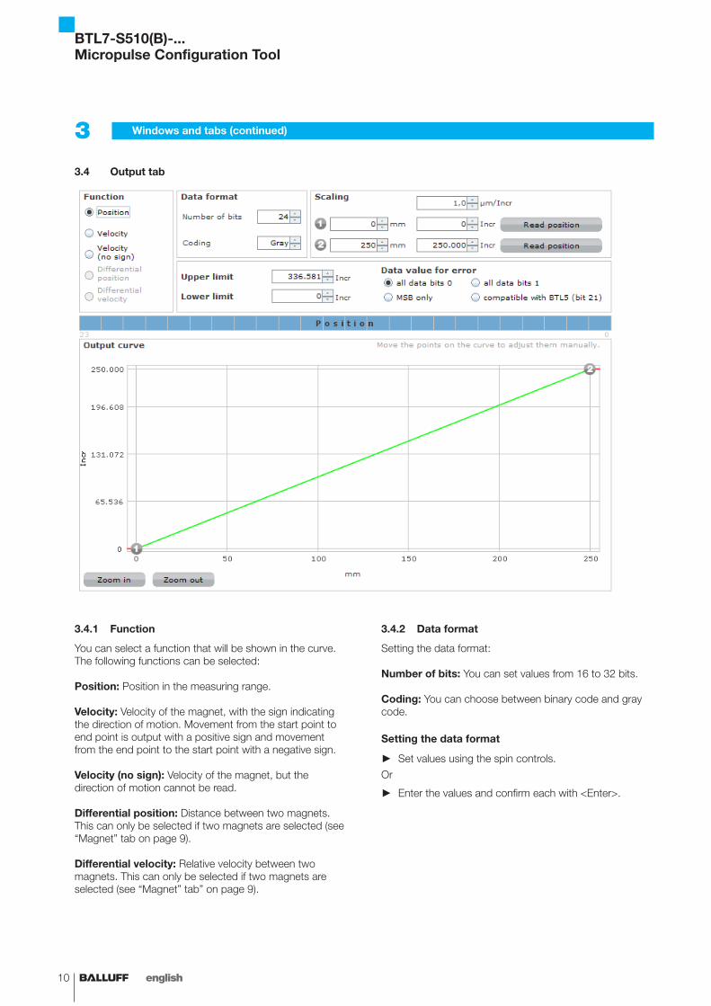
3.4 Output tab
3.4.1 Function
You can select a function that will be shown in the curve. The following functions can be selected:
Position: Position in the measuring range.
Velocity: Velocity of the magnet, with the sign indicating the direction of motion. Movement from the start point to end point is output with a positive sign and movement from the end point to the start point with a negative sign.
Velocity (no sign): Velocity of the magnet, but the direction of motion cannot be read.
Differential position: Distance between two magnets. This can only be selected if two magnets are selected (see “Magnet” tab on page 9).
Differential velocity: Relative velocity between two magnets. This can only be selected if two magnets are selected (see “Magnet” tab” on page 9).
3.4.2 Data format
Setting the data format:
Number of bits: You can set values from 16 to 32 bits.
Coding: You can choose between binary code and gray code.
Setting the data format
► Set values using the spin controls.
Or
► Enter the values and confirm each with <Enter>.
3 Windows and tabs (continued)
BTL7-S510(B)-...Micropulse Configuration Tool
11englishwww.balluff.com
3.4.3 Scaling
The resolution is specified by the curve gradient; the measuring range is specified by the start point and end point.
: Start point of the curve with associated output value.
: End point of the curve with associated output value.
Read position: The present position of the magnet is read (teach-in).
To set the values, see also “Setting the curve” in Section 3.4.6.
Setting the resolution
The curve gradient can be changed by fixed increments. ► Set value using the spin controls under Scaling.
Setting the start points and end points ► For the start point and end point, the present position
of the magnet on the transducer is read (teach-in).
Or
► Use the mouse to move the start point and end point in the graphical display.
Or
► Set values using the spin controls.
Or
► Enter values and confirm each by pressing <Enter>.You might have to first adjust the limits and error value in order to set the scaling.
3.4.4 Limits and error value
Setting upper limit, lower limit, and error value
Measuring range/limits: The start and end points must lie on or within the limits and they must keep a minimum distance from the error value.
Error value: The error value must lie on or outside of the limits. A minimum distance from the start or end point of the measuring range must be kept.
The error value “all data bits 1” and “MSB only” can only be selected if the bit number is ≤ 25. The error value “compatible with BTL5 (bit 21)” is only possible if the bit number is ≥ 22.
Setting limits and error value
► Set values using the spin controls.
Or
► Enter values and confirm by pressing <Enter>. ► Select the appropriate error value.
3.4.5 Blue bar
The selected function (see 3.4.1) is shown and the data format for the SSI interface (see 3.4.2) is displayed graphically in the blue bar over the output characteristics.
3.4.6 Output characteristics
Graphical representation of the curve as a function of the scaling.
Offset and gradient are displayed when the mouse cursor is moved over the start point or end point .
Setting the curve
► Use the mouse to move the points. ⇒ The curve and associated values will be changed.
Note the following when making this setting: – For “Position”, the distance between the start point
and end point must be at least 4 mm (0.15 inches). – For “Velocity”, the distance between the start point and
end point must be at least 100 mm/s (4 inches/s). – Identical values may not be selected for the start point
and end point. – The minimum nominal length of the transducer for the
“Differential position” function is 90 mm. – For the “Differential position” function, the minimum
distance between two magnets is 65 mm. – The maximum configurable velocity is 10 m/s.
Values and settings in blue text indicate changes to the configuration. Update transdUcer sends the configuration to the transducer.
Check outputThe results of the configuration are displayed online on the “Magnet” tab.
► Click on Update transdUcer. ⇒ The configuration is sent to the transducer.
► Switch to “Magnet” tab. ⇒ The set function is displayed. ⇒ The movements of the magnets and the LED
signals are shown online.
Negative values can only be output in binary format if the bit number is ≤ 25. Negative values in gray format are only possible if the bit number is = 25.
3 Windows and tabs (continued)
BTL7-S510(B)-...Micropulse Configuration Tool
12 english
The menu commands can be called up via the menu bar or directly using key combinations (shortcuts).
Clicking on www.BallUFF.com opens the Balluff website. This requires that the PC be connected to the Internet.
4.1 “File” menu
4.1.1 Open <Ctrl> + <O>
Opens the “Open” dialog box. A saved configuration can be loaded (file extension “dat”).
If the type is identical, a prompt appears and the transducer can be updated.
If the prompt is not confirmed or the type is not identical, the Configuration Tool switches to offline mode (see “Settings” menu in Section 4.3).
4.1.2 Save <Ctrl> + <S>
Opens up the “Save” dialog box, a configuration can be saved as a file (file extension “dat”). The configuration currently located in the Configuration Tool is saved, regardless of whether it was sent to the transducer or not.
4.1.3 Report <Ctrl> + <E>
Calls up a text file (temp.txt) that documents the information on the transducer and its current settings. It can be stored under a new name.
4.1.4 Exit <Ctrl> + <X>
Exits the Configuration Tool. If the transducer is not yet updated, a prompt appears. The exit process can be cancelled.
4.2 “Transducer” menu
4.2.1 Read <Ctrl> + <R>
The configuration of the connected transducer is read. Reading must be acknowledged. The current configuration in the Configuration Tool is overwritten.
4.2.2 Factory settings <Ctrl> + <F>
Resets the configuration of the connected transducer to the factory settings. Resetting must be confirmed.
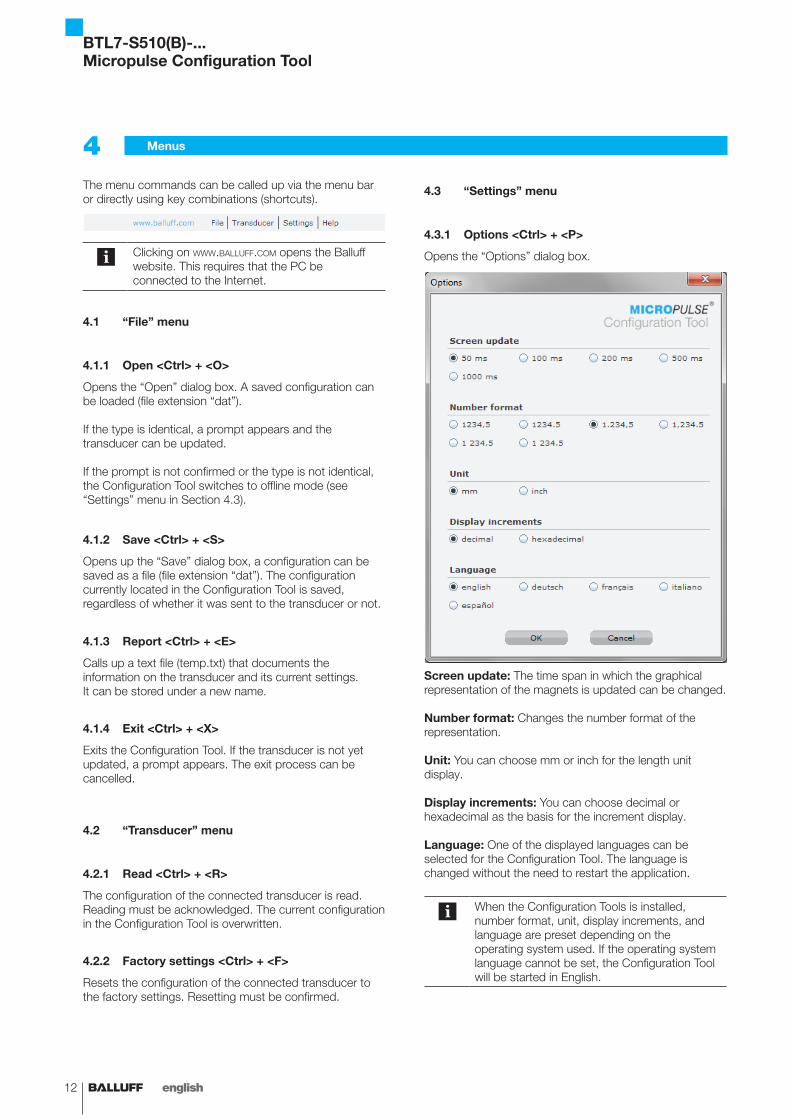
4.3 “Settings” menu
4.3.1 Options <Ctrl> + <P>
Opens the “Options” dialog box.
Screen update: The time span in which the graphical representation of the magnets is updated can be changed.
Number format: Changes the number format of the representation.
Unit: You can choose mm or inch for the length unit display.
Display increments: You can choose decimal or hexadecimal as the basis for the increment display.
Language: One of the displayed languages can be selected for the Configuration Tool. The language is changed without the need to restart the application.
When the Configuration Tools is installed, number format, unit, display increments, and language are preset depending on the operating system used. If the operating system language cannot be set, the Configuration Tool will be started in English.
4 Menus
BTL7-S510(B)-...Micropulse Configuration Tool
13englishwww.balluff.com
4.3.2 Offline/Online <Ctrl> + <L>
Switches from online mode to offline mode and vice versa. Online: The transducer is connected to the Configuration Tool and can be updated at any time. Data is continually sent, e.g. LED states and positions.
Offline: The transducer is not connected to the Configuration Tool. The present configuration can be edited or a new configuration can be opened. You must switch to online mode to send the configuration.
Switching from “Online” to “Offline”: ► Call up “Settings > Offline” (<Ctrl> + <L>).
⇒ The Configuration Tool switches to offline mode.
Switching from “Offline” to “Online”: ► Call up “Settings > Online” (<Ctrl> + <L>).
⇒ The Configuration Tool switches to online mode.
If another transducer of the same type is connected in offline mode, a prompt with the following options appears when switching to online mode: – Read: Read the transducer configuration. The current
configuration in the Configuration Tool will be overwritten.
– Update: The transducer is updated with the current configuration in the Configuration Tool.
– Offline: Perform no action, remain in offline mode.
The current connection status is shown in the main window.
4.4 “Help” menu
4.4.1 Info <Ctrl> + <I>
Shows the current software version number and the service contact data.
4.4.2 Download <Ctrl> + <D>
Opens an Internet connection for downloading the latest software version, as well as the current manual. This requires that the PC be connected to the Internet.
4 Menus (continued)
BTL7-S510(B)-...Micropulse Configuration Tool

No.
868
143-
726
E .
02.1
1455
8 . E
ditio
n 12
07; S
ubje
ct to
mod
ifica
tion.
. R
epla
ces
editi
on 1
009.
www.balluff.com
Headquarters GermanyBalluff GmbHSchurwaldstrasse 973765 Neuhausen a.d.F.Phone + 49 7158 173-0Fax +49 7158 [email protected]
Global Service Center
GermanyBalluff GmbHSchurwaldstrasse 973765 Neuhausen a.d.F.Phone +49 7158 173-370Fax +49 7158 [email protected]
US Service Center
USABalluff Inc.8125 Holton DriveFlorence, KY 41042Phone (859) 727-2200Toll-free 1-800-543-8390Fax (859) 727-4823 [email protected]
CN Service Center
ChinaBalluff (Shanghai) trading Co., ltd.Room 1006, Pujian Rd. 145. Shanghai, 200127, P.R. China Phone +86 (21) 5089 9970Fax +86 (21) 5089 [email protected]