Embed Size (px)
Citation preview
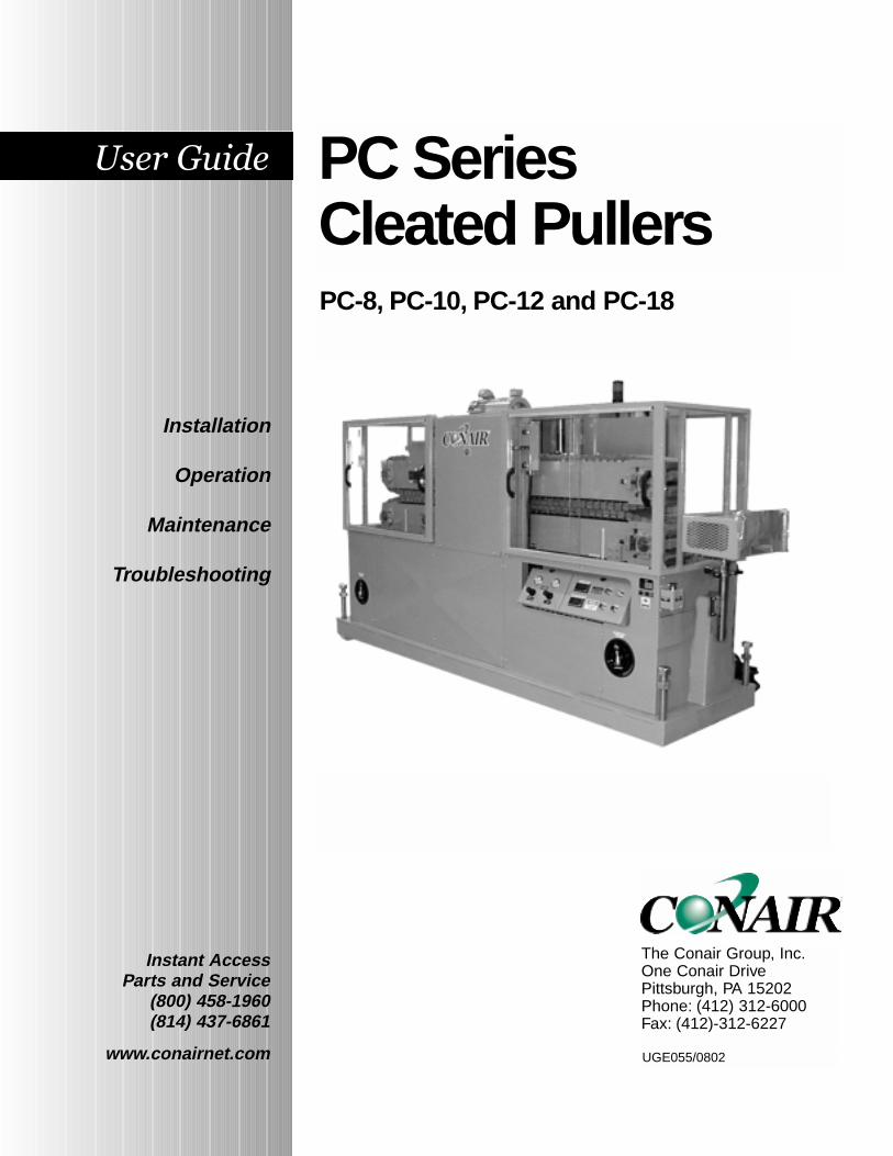
PC Series Cleated Pullers
Instant Access Parts and Service
(800) 458-1960(814) 437-6861
www.conairnet.com
The Conair Group, Inc.One Conair DrivePittsburgh, PA 15202Phone: (412) 312-6000Fax: (412)-312-6227
PC-8, PC-10, PC-12 and PC-18
UGE055/0802
Installation
Operation
Maintenance
Troubleshooting
It is important to record the model and serial number(s) ofyour equipment and the date you received it in the UserGuide. Our service department uses this information, alongwith the manual number, to provide help for the specificequipment you installed.
Keep this User Guide and all manuals, engineering prints andparts lists together for documentation of your equipment.
Date:
Document Number: UGE055/0802
Serial number(s):
Model number(s):
Power Specifications:
AmpsVoltsPhaseCycle
DISCLAIMER: The Conair Group, Inc., shall not be liable for errorscontained in this User Guide or for incidental, consequential dam-ages in connection with the furnishing, performance or use of thisinformation. Conair makes no warranty of any kind with regard tothis information, including, but not limited to the implied warrantiesof merchantability and fitness for a particular purpose.
Record your equipment’smodel and serial num-ber(s) and the date youreceived it in the spacesprovided.
Copyright 2002 All rights reservedTHE CONAIR GROUP, INC.
UGE055/0802 PC Series CleatedPullers
TABLE OFCONTENTS
INTRODUCTION . . . . . . . . . . . . . . . . . . .1-1Purpose of the User Guide . . . . . . . . . . . . . . . . . . . . . . . . .1-2How the Guide is Organized . . . . . . . . . . . . . . . . . . . . . . .1-2Your Responsibilities as a User . . . . . . . . . . . . . . . . . . . . .1-2ATTENTION: Read this so no one gets hurt . . . . . . . . . . .1-3How to Use the Lockout Device . . . . . . . . . . . . . . . . . . . .1-5
DESCRIPTION . . . . . . . . . . . . . . . . . . . .2-1What is the PC Series Cleated Puller? . . . . . . . . . . . . . . . .2-2Typical Applications . . . . . . . . . . . . . . . . . . . . . . . . . . . . .2-2How It Works (the optional footage counter) . . . . . . . . . . .2-3PC Series Cleated Puller Features . . . . . . . . . . . . . . . . . . .2-4Specifications . . . . . . . . . . . . . . . . . . . . . . . . . . . . . . . . . .2-5Options . . . . . . . . . . . . . . . . . . . . . . . . . . . . . . . . . . . . . . .2-7
INSTALLATION . . . . . . . . . . . . . . . . . . . .3-1Unpacking the Boxes . . . . . . . . . . . . . . . . . . . . . . . . . . . . .3-2Preparing for Installation . . . . . . . . . . . . . . . . . . . . . . . . . .3-3Installing the Puller . . . . . . . . . . . . . . . . . . . . . . . . . . . . . .3-4Connecting the Main Power . . . . . . . . . . . . . . . . . . . . . . . .3-5Adjusting Cleated Chain Tension . . . . . . . . . . . . . . . . . . . .3-6Setting the Cleat Gap . . . . . . . . . . . . . . . . . . . . . . . . . . . . .3-7Testing the Installation . . . . . . . . . . . . . . . . . . . . . . . . . . . .3-8
OPERATION . . . . . . . . . . . . . . . . . . . . . .4-1The Puller Control . . . . . . . . . . . . . . . . . . . . . . . . . . . . . . .4-2Starting the Puller . . . . . . . . . . . . . . . . . . . . . . . . . . . . . . .4-3Operation . . . . . . . . . . . . . . . . . . . . . . . . . . . . . . . . . . . . . .4-4Stopping the Puller . . . . . . . . . . . . . . . . . . . . . . . . . . . . . .4-5Shutting Down . . . . . . . . . . . . . . . . . . . . . . . . . . . . . . . . . .4-5
MAINTENANCE . . . . . . . . . . . . . . . . . . . .5-1Preventative Maintenance Schedule . . . . . . . . . . . . . . . . . .5-2Replacing Cleats . . . . . . . . . . . . . . . . . . . . . . . . . . . . . . . .5-6Lubricating Shafts and Fittings . . . . . . . . . . . . . . . . . . . . .5-7Replacing Motor Brushes . . . . . . . . . . . . . . . . . . . . . . . . . .5-8Checking Electrical Connections . . . . . . . . . . . . . . . . . . . .5-9
i
PC Series Cleated Pullers UGE055/0802
TROUBLESHOOTING . . . . . . . . . . . . . . . .6-1Before Beginning . . . . . . . . . . . . . . . . . . . . . . . . . . . . . . . .6-2A Few Words of Caution . . . . . . . . . . . . . . . . . . . . . . . . . .6-2Identify the Cause of a Problem . . . . . . . . . . . . . . . . . . . . .6-3Operation Problems . . . . . . . . . . . . . . . . . . . . . . . . . . . . . .6-4Product Quality Problems . . . . . . . . . . . . . . . . . . . . . . . . .6-5
APPENDIX . . . . . . . . . . . . . . . . . . . . . . . . .Customer Service . . . . . . . . . . . . . . . . . . . . . . . . . . . . . . .A-1Warranty Information . . . . . . . . . . . . . . . . . . . . . . . . . . . .A-2Belt Adjustment Options . . . . . . . . . . . . . . . . . . . . . . . . . .B-1Using the Digital Belt Gap Sensor . . . . . . . . . . . . . . . . . . .B-1Adjusting the Pneumatic Upper Belt Actuator . . . . . . . . . .B-2
ii
1-1UGE055/0802 PC Series Cleated Pullers
�� Purpose of the User Guide . . . .1-2�� How the User Guide
is Organized . . . . . . . . . . . . . .1-2��Your Responsibilities
as a User . . . . . . . . . . . . . . . .1-2�� ATTENTION: Read this so
no one gets hurt . . . . . . . . . . .1-3�� How to Use the
Lockout Device . . . . . . . . . . . .1-5
INTRODUCTION
PC Series Cleated Pullers 1-2 INTRODUCTION
This User Guide describes the Conair PC Series CleatedPullers and explains step-by-step how to install, operate,maintain and repair this equipment.
Before installing this product, please take a few moments toread the User Guide and review the diagrams and safety infor-mation in the instruction packet. You also should review man-uals covering associated equipment in your system. Thisreview won’t take long, and it could save you valuable instal-lation and operating time later.
Symbols have been used to help organize the User Guide andcall your attention to important information regarding safeinstallation and operation.
Symbols within triangles warn of conditions that couldbe hazardous to users or could damage equipment.Read and take precautions before proceeding.Numbers within shaded squares indicate tasks or stepsto be performed by the user.
A diamond indicates the equipment’s response to anaction performed by the user.
An open box marks items in a checklist.
A shaded circle marks items in a list.
You must be familiar with all safety procedures concerninginstallation, operation and maintenance of this equipment.Responsible safety procedures include:
� Thorough review of this User Guide, paying particularattention to hazard warnings, appendices and related dia-grams.
� Thorough review of the equipment itself, with carefulattention to voltage sources, intended use and warninglabels.
� Thorough review of instruction manuals for associatedequipment.
� Step-by-step adherence to instructions outlined in thisUser Guide.
PURPOSE OFTHE USERGUIDE
HOW THEUSER GUIDE ISORGANIZED
1
�
�
�
YOURRESPONSIBILITYAS A USER
INTRODUCTION 1-3
We design equipment with the user’s safety in mind. You canavoid the potential hazards identified on this machine by fol-lowing the procedures outlined below and elsewhere in theUser Guide.
ATTENTION:READ THIS SO NOONE GETS HURT
UGE055/0802 PC Series Cleated Pullers
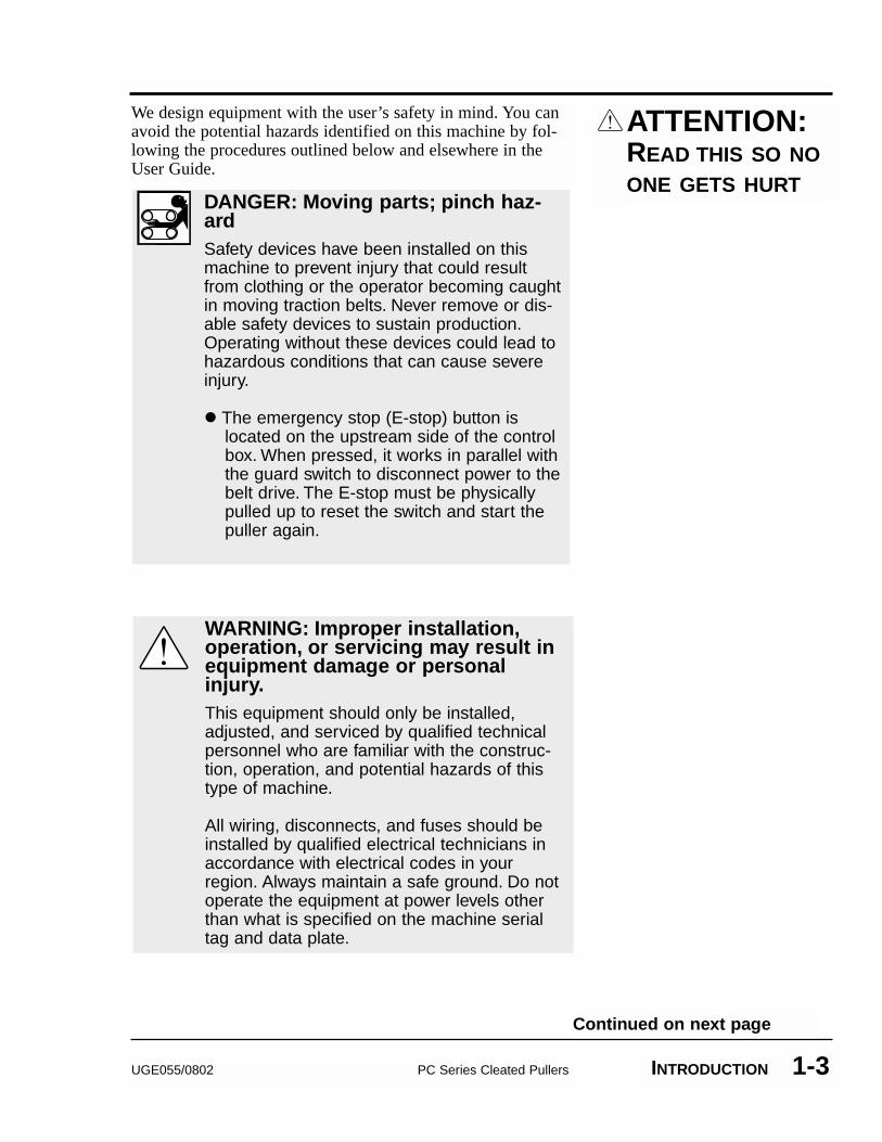
DANGER: Moving parts; pinch haz-ardSafety devices have been installed on thismachine to prevent injury that could resultfrom clothing or the operator becoming caughtin moving traction belts. Never remove or dis-able safety devices to sustain production.Operating without these devices could lead tohazardous conditions that can cause severeinjury.
� The emergency stop (E-stop) button islocated on the upstream side of the controlbox. When pressed, it works in parallel withthe guard switch to disconnect power to thebelt drive. The E-stop must be physicallypulled up to reset the switch and start thepuller again.
WARNING: Improper installation,operation, or servicing may result inequipment damage or personalinjury.This equipment should only be installed,adjusted, and serviced by qualified technicalpersonnel who are familiar with the construc-tion, operation, and potential hazards of thistype of machine.
All wiring, disconnects, and fuses should beinstalled by qualified electrical technicians inaccordance with electrical codes in yourregion. Always maintain a safe ground. Do notoperate the equipment at power levels otherthan what is specified on the machine serialtag and data plate.
Continued on next page
PC Series Cleated Pullers UGE055/08021-4 INTRODUCTION
WARNING: Voltage HazardThis equipment is powered by three-phasealternating current, as specified on themachine serial tag and data plate.
A properly-sized conductive ground wire fromthe incoming power supply must be connectedto the chassis ground terminal inside the elec-trical enclosure. Improper grounding can resultin sever personal injury and erratic machineoperation.
Always disconnect and lockout powerbefore opening the electrical enclosure orperforming non-routine procedures such asmaintenance.
ATTENTION:READ THIS SO NOONE GETS HURT
HOW TO USETHE LOCKOUTDEVICE
UGE055/0802 PC Series Cleated Pullers INTRODUCTION 1-5
WARNING: Electrical hazardBefore performing maintenance or repairs onthis product, disconnect and lock out electricalpower sources to prevent injury from unexpect-ed energization or start-up. A lockable devicehas been provided to isolate this product frompotentially hazardous electricity.
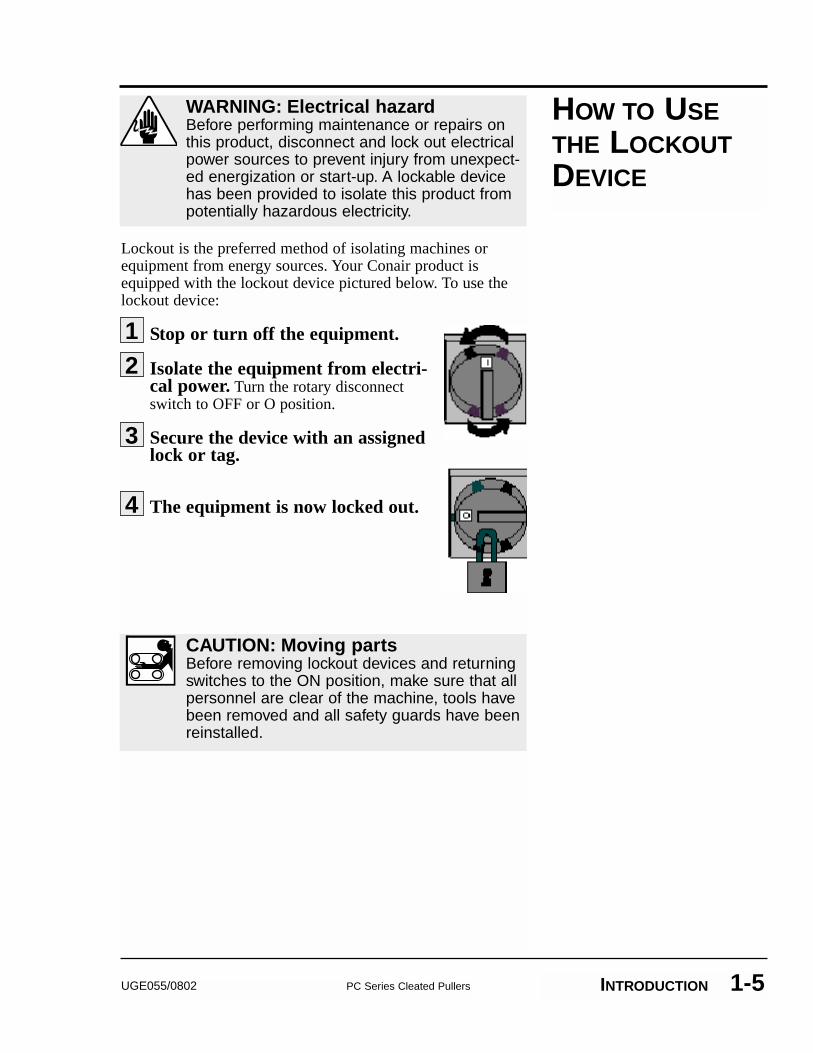
Lockout is the preferred method of isolating machines orequipment from energy sources. Your Conair product isequipped with the lockout device pictured below. To use thelockout device:
Stop or turn off the equipment.
Isolate the equipment from electri-cal power. Turn the rotary disconnectswitch to OFF or O position.
Secure the device with an assignedlock or tag.
The equipment is now locked out.
CAUTION: Moving partsBefore removing lockout devices and returningswitches to the ON position, make sure that allpersonnel are clear of the machine, tools havebeen removed and all safety guards have beenreinstalled.
3
4
12

2-1UGE055/0802 PC Series Cleated Pullers
�� What is the PC Series Cleated Puller? . . . . . . . . . . . . . .2-2
�� Typical Applications . . . . . . . . . .2-2�� How it works (the optional footage
counter) . . . . . . . . . . . . . . . . . . .2-3�� PC Series Cleated Belt Puller
Features . . . . . . . . . . . . . . . . . . .2-4�� Specifications . . . . . . . . . . . . . .2-5�� Options . . . . . . . . . . . . . . . . . . . .2-6
DESCRIPTION
Conair PC Series Cleated Pullers are designed to consistently pullmedium to large-sized extruded products through sizing and/orcooling tanks.
The standard chain drive system is suitable for applicationsrequiring relatively high pulling force. The hardened chaindrive gears protected with high temperature grease make thechain drive shaft pullers a good choice for high torque, lowspeed applications.
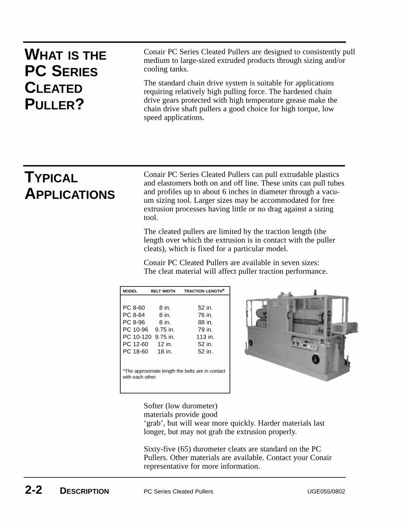
Conair PC Series Cleated Pullers can pull extrudable plasticsand elastomers both on and off line. These units can pull tubesand profiles up to about 6 inches in diameter through a vacu-um sizing tool. Larger sizes may be accommodated for freeextrusion processes having little or no drag against a sizingtool.
The cleated pullers are limited by the traction length (thelength over which the extrusion is in contact with the pullercleats), which is fixed for a particular model.
Conair PC Cleated Pullers are available in seven sizes:The cleat material will affect puller traction performance.
Softer (low durometer) materials provide good‘grab’, but will wear more quickly. Harder materials lastlonger, but may not grab the extrusion properly.
Sixty-five (65) durometer cleats are standard on the PCPullers. Other materials are available. Contact your Conairrepresentative for more information.
WHAT IS THEPC SERIESCLEATEDPULLER?
PC Series Cleated Pullers UGE055/08022-2 DESCRIPTION
TYPICALAPPLICATIONS
MODEL BELT WIDTH TRACTION LENGTH*
PC 8-60 8 in. 52 in.PC 8-84 8 in. 76 in.PC 8-96 8 in. 88 in.PC 10-96 9.75 in. 79 in.PC 10-120 9.75 in. 113 in.PC 12-60 12 in. 52 in.PC 18-60 18 in. 52 in.
*The approximate length the belts are in contactwith each other.
UGE055/0802 PC Series Cleated Pullers DESCRIPTION 2-3
HOW IT WORKS:THE RATEINDICATOR
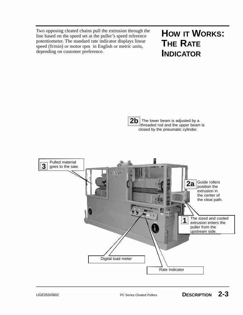
Two opposing cleated chains pull the extrusion through theline based on the speed set at the puller’s speed referencepotentiometer. The standard rate indicator displays linearspeed (ft/min) or motor rpm in English or metric units,depending on customer preference.
Guide rollersposition theextrusion inthe center ofthe cleat path.
2a
The sized and cooledextrusion enters thepuller from theupstream side.
1
The lower beam is adjusted by athreaded rod and the upper beam is
closed by the pneumatic cylinder.
2b
Pulled materialgoes to the saw.3
Digital load meter
Rate Indicator
PC SERIES CLEATED PULLER FEATURES
PC Series Cleated Pullers UGE055/08022-4 DESCRIPTION
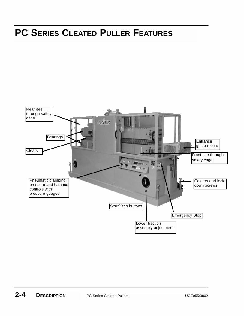
Emergency Stop
Entranceguide rollers
Front see through-safety cage
Start/Stop buttons
Cleats
Rear seethrough safety cage
Bearings
Casters and lockdown screws
Pneumatic clampingpressure and balancecontrols with pressure guages
Lower traction assembly adjustment
UGE055/0802 PC Series Cleated Pullers DESCRIPTION 2-5
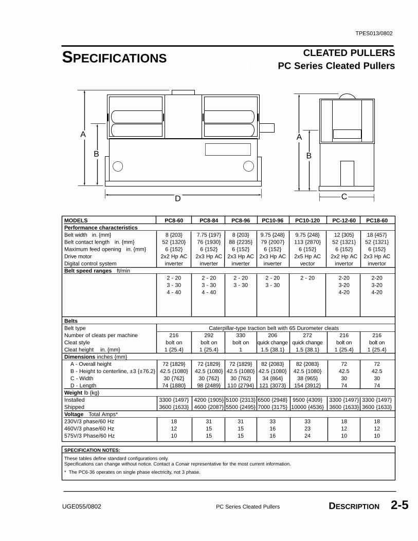
CLEATED PULLERSPC Series Cleated Pullers
TPES013/0802
MODELS PC8-60 PC8-84 PC8-96 PC10-96 PC10-120 PC-12-60 PC18-60Performance characteristicsBelt width in. {mm} 8 {203} 7.75 {197} 8 {203} 9.75 {248} 9.75 {248} 12 {305} 18 {457}Belt contact length in. {mm} 52 {1320} 76 {1930} 88 {2235} 79 {2007} 113 {2870} 52 {1321} 52 {1321}Maximum feed opening in. {mm} 6 {152} 6 {152} 6 {152} 6 {152} 6 {152} 6 {152} 6 {152}Drive motor 2x2 Hp AC 2x3 Hp AC 2x3 Hp AC 2x3 Hp AC 2x5 Hp AC 2x2 Hp AC 2x3 Hp ACDigital control system inverter inverter inverter inverter vector invertor invertorBelt speed ranges ft/min
2 - 20 2 - 20 2 - 20 2 - 20 2 - 20 2-20 2-203 - 30 3 - 30 3 - 30 3 - 30 3-20 3-204 - 40 4 - 40 4-20 4-20
BeltsBelt type Caterpillar-type traction belt with 65 Durometer cleatsNumber of cleats per machine 216 292 330 206 272 216 216Cleat style bolt on bolt on bolt on quick change quick change bolt on bolt on Cleat height in. {mm} 1 {25.4} 1 {25.4} 1 1.5 {38.1} 1.5 {38.1} 1 {25.4} 1 {25.4}Dimensions inches {mm}
A - Overall height 72 {1829} 72 {1829} 72 {1829} 82 {2083} 82 {2083} 72 72B - Height to centerline, ±3 {±76.2} 42.5 {1080} 42.5 {1080} 42.5 {1080} 42.5 {1080} 42.5 {1080} 42.5 42.5C - Width 30 {762} 30 {762} 30 {762} 34 {864} 38 {965} 30 30D - Length 74 {1880} 98 {2489} 110 {2794} 121 {3073} 154 {3912} 74 74
Weight lb {kg}Installed 3300 {1497} 4200 {1905} 5100 {2313} 6500 {2948} 9500 {4309} 3300 {1497} 3300 {1497}Shipped 3600 {1633} 4600 {2087} 5500 {2495} 7000 {3175} 10000 {4536} 3600 {1633} 3600 {1633}Voltage Total Amps*230V/3 phase/60 Hz 18 31 31 33 33 18 18460V/3 phase/60 Hz 12 15 15 16 23 12 12575V/3 Phase/60 Hz 10 15 15 16 24 10 10
A A
B B
D C
SPECIFICATION NOTES:
These tables define standard configurations only.Specifications can change without notice. Contact a Conair representative for the most current information.
* The PC6-36 operates on single phase electricity, not 3 phase.
SPECIFICATIONS
OPTIONS �� Different reducer ratiosA particular reducer ratio is selected at the time of pur-chase to optimize puller performance in a particular speedrange.
�� Left-to-right machine operationThis option changes the machine direction from the stan-dard right to left extrusion flow.
� Transformer for 575 Volt
�� Adder for 1.5 inch cleats reduces maximum opening by 1 inch.
�� Adder for 2 inch cleats reduces maximum opening by 2 inches
�� Profiled cleatscleat drawing required
�� Quick Change Cleats
�� Closed loop vector driveFor improved speed regulation and increased 50:1 speed range.
UGE055/0802 PC Series Cleated Pullers DESCRIPTION 2-6
3-1UGE055/0802 PC Series Cleated Pullers
�� Unpacking the Boxes . . . . . . . . .3-2�� Preparing for Installation . . . . . .3-3�� Installing the Puller . . . . . . . . . .3-4�� Connecting the Main Power . . . .3-5�� Adjusting Cleated
Chain Tension . . . . . . . . . . . . . . .3-6�� Setting the Cleat Gap . . . . . . . . .3-7�� Testing the Installation . . . . . . . .3-8
INSTALLATION
UNPACKING THEBOXES
PC Series Cleated Pullers UGE055/08023-2 INSTALLATION
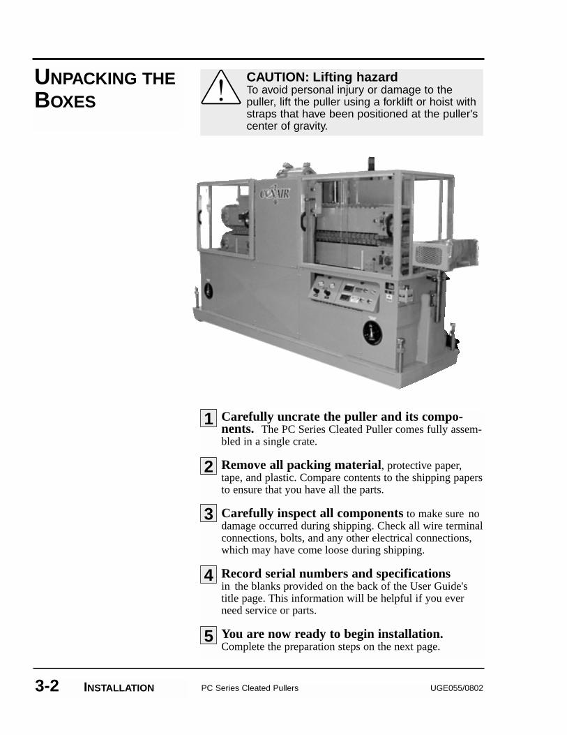
Carefully uncrate the puller and its compo-nents. The PC Series Cleated Puller comes fully assem-bled in a single crate.
Remove all packing material, protective paper,tape, and plastic. Compare contents to the shipping papersto ensure that you have all the parts.
Carefully inspect all components to make sure nodamage occurred during shipping. Check all wire terminalconnections, bolts, and any other electrical connections,which may have come loose during shipping.
Record serial numbers and specificationsin the blanks provided on the back of the User Guide's title page. This information will be helpful if you everneed service or parts.
You are now ready to begin installation.Complete the preparation steps on the next page.
CAUTION: Lifting hazardTo avoid personal injury or damage to thepuller, lift the puller using a forklift or hoist withstraps that have been positioned at the puller'scenter of gravity.
2
3
4
5
1
You will install the puller on the extrusion line, downstreamof the extruder and any calibration/sizing equipment.
Make sure the installation area provides:� A grounded power source supplying the correct
current and voltage. Check the serial tag for the cor-rect amps, voltage, phase and cycles. All wiringshould be completed by qualified personnel andshould comply with your region’s electrical codes.
� Minimum clearance for safe operation and mainte-nance. Allow at least 12 to 24 inches (305 to 610mm) between the downstream end of sizing or cool-ing tanks and the upstream end of the puller to rollthe tank away from the extruder for maintenance.Allow at least 36 inches clearance in front and backof the puller for maintenance access to electrical andmechanical systems.
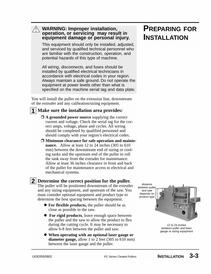
Determine the correct position for the puller. The puller will be positioned downstream of the extruderand any sizing equipment, and upstream of the saw. Youmust consider optional equipment and product type todetermine the best spacing between the equipment.
� For flexible products, the puller should be as close as possible to the saw.
� For rigid products, leave enough space betweenthe puller and the saw to allow the product to flexduring the cutting cycle. It may be necessary toallow 6-8 feet between the puller and saw.
� When operating with an optional laser gauge ordiameter gauge, allow 1 to 2 feet (305 to 610 mm)between the laser gauge and the puller.
PREPARING FORINSTALLATION
UGE055/0802 PC Series Cleated Pullers INSTALLATION 3-3
1
2
WARNING: Improper installation,operation, or servicing may result inequipment damage or personal injury.This equipment should only be installed, adjusted,and serviced by qualified technical personnel whoare familiar with the construction, operation, andpotential hazards of this type of machine.
All wiring, disconnects, and fuses should beinstalled by qualified electrical technicians inaccordance with electrical codes in your region.Always maintain a safe ground. Do not operate theequipment at power levels other than what isspecified on the machine serial tag and data plate.
12 to 24 inchesbetween puller and laser
gauge or sizing equipment
distancebetween puller
and sawdepends onproduct type
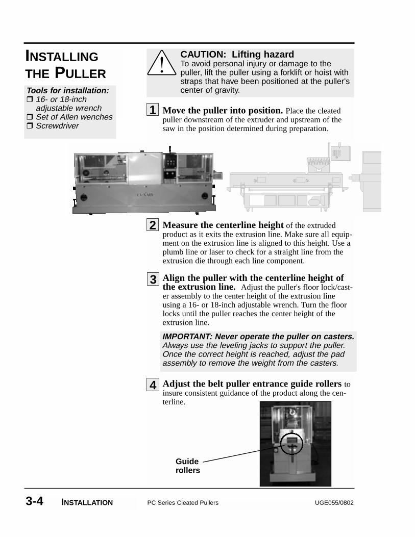
Move the puller into position. Place the cleatedpuller downstream of the extruder and upstream of thesaw in the position determined during preparation.
Measure the centerline height of the extrudedproduct as it exits the extrusion line. Make sure all equip-ment on the extrusion line is aligned to this height. Use aplumb line or laser to check for a straight line from theextrusion die through each line component.
Align the puller with the centerline height ofthe extrusion line. Adjust the puller's floor lock/cast-er assembly to the center height of the extrusion lineusing a 16- or 18-inch adjustable wrench. Turn the floorlocks until the puller reaches the center height of theextrusion line.
Adjust the belt puller entrance guide rollers toinsure consistent guidance of the product along the cen-terline.
PC Series Cleated Pullers UGE055/08023-4 INSTALLATION
1
INSTALLINGTHE PULLER
CAUTION: Lifting hazardTo avoid personal injury or damage to thepuller, lift the puller using a forklift or hoist withstraps that have been positioned at the puller'scenter of gravity.
2
3
4
Tools for installation:� 16- or 18-inch
adjustable wrench� Set of Allen wenches� Screwdriver
IMPORTANT: Never operate the puller on casters.Always use the leveling jacks to support the puller.Once the correct height is reached, adjust the padassembly to remove the weight from the casters.
Guiderollers
UGE055/0802 PC Series Cleated Pullers INSTALLATION 3-5
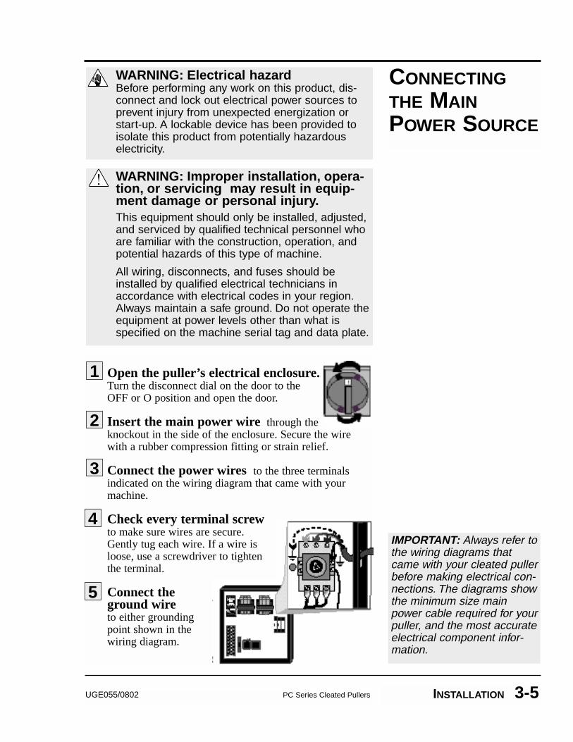
Open the puller’s electrical enclosure.Turn the disconnect dial on the door to theOFF or O position and open the door.
Insert the main power wire through theknockout in the side of the enclosure. Secure the wirewith a rubber compression fitting or strain relief.
Connect the power wires to the three terminals indicated on the wiring diagram that came with yourmachine.
Check every terminal screwto make sure wires are secure.Gently tug each wire. If a wire isloose, use a screwdriver to tightenthe terminal.
Connect theground wireto either groundingpoint shown in thewiring diagram.
1
2
IMPORTANT: Always refer tothe wiring diagrams thatcame with your cleated pullerbefore making electrical con-nections. The diagrams showthe minimum size mainpower cable required for yourpuller, and the most accurateelectrical component infor-mation.
CONNECTINGTHE MAINPOWER SOURCE
3
WARNING: Electrical hazardBefore performing any work on this product, dis-connect and lock out electrical power sources toprevent injury from unexpected energization orstart-up. A lockable device has been provided toisolate this product from potentially hazardouselectricity.
WARNING: Improper installation, opera-tion, or servicing may result in equip-ment damage or personal injury.This equipment should only be installed, adjusted,and serviced by qualified technical personnel whoare familiar with the construction, operation, andpotential hazards of this type of machine.
All wiring, disconnects, and fuses should beinstalled by qualified electrical technicians inaccordance with electrical codes in your region.Always maintain a safe ground. Do not operate theequipment at power levels other than what isspecified on the machine serial tag and data plate.
4
5
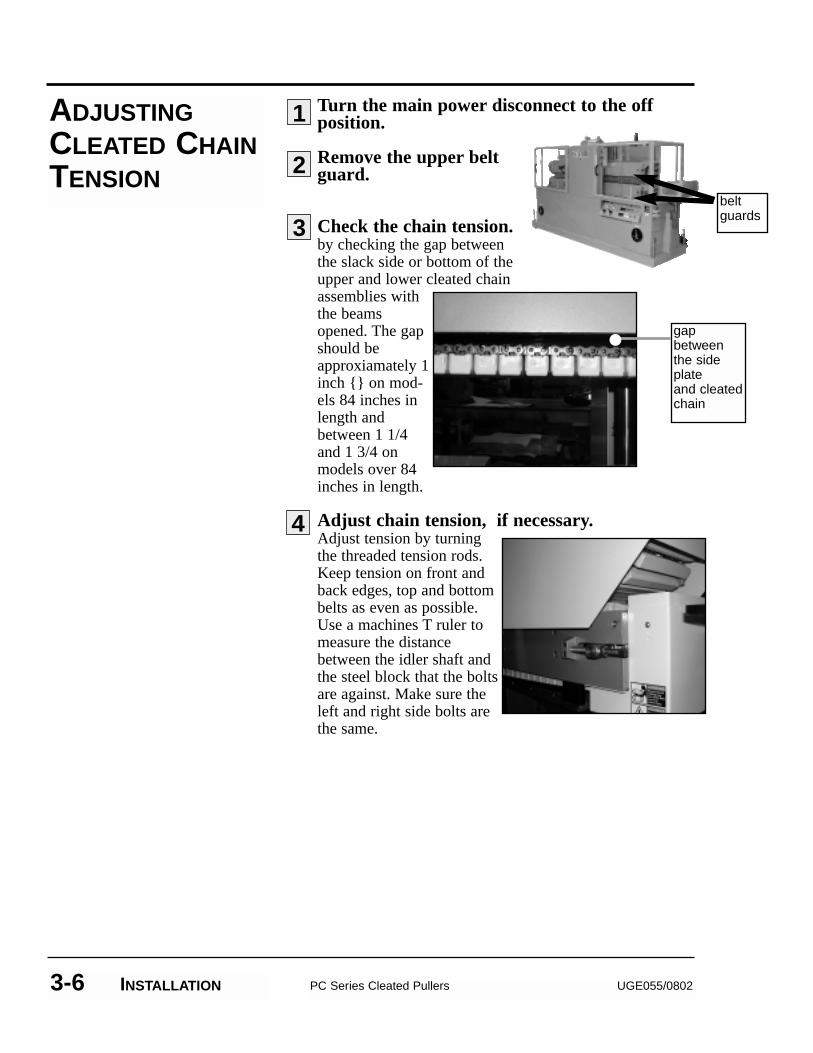
Turn the main power disconnect to the offposition.
Remove the upper beltguard.
Check the chain tension. by checking the gap betweenthe slack side or bottom of theupper and lower cleated chainassemblies withthe beamsopened. The gapshould beapproxiamately 1inch {} on mod-els 84 inches inlength andbetween 1 1/4and 1 3/4 onmodels over 84inches in length.
Adjust chain tension, if necessary.Adjust tension by turningthe threaded tension rods.Keep tension on front andback edges, top and bottombelts as even as possible.Use a machines T ruler tomeasure the distancebetween the idler shaft andthe steel block that the boltsare against. Make sure theleft and right side bolts arethe same.
PC Series Cleated Pullers UGE055/08023-6 INSTALLATION
ADJUSTINGCLEATED CHAINTENSION
1
2
3
4
beltguards
gapbetweenthe sideplate and cleated chain
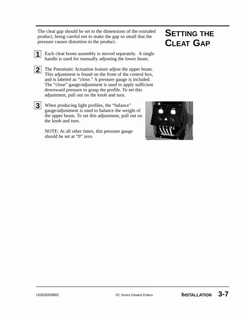
The cleat gap should be set to the dimensions of the extrudedproduct, being careful not to make the gap so small that thepressure causes distortion in the product.
Each cleat boom assembly is moved separately. A singlehandle is used for manually adjusting the lower beam.
The Pneumatic Actuation feature adjust the upper beam.This adjustment is found on the front of the control box,and is labeled as “close.” A pressure gauge is included.The “close” gauge/adjustment is used to apply sufficientdownward pressure to grasp the profile. To set thisadjustment, pull out on the knob and turn.
When producing light profiles, the “balance”gauge/adjustment is used to balance the weight ofthe upper beam. To set this adjustment, pull out onthe knob and turn.
NOTE: At all other times, this pressure gaugeshould be set at “0” zero.
UGE055/0802 PC Series Cleated Pullers INSTALLATION 3-7
SETTING THECLEAT GAP
1
2
3
3-8 INSTALLATION
TESTING THEINSTALLATION
PC Series Cleated Pullers UGE055/0802
Make sure all components are installed accordingto assembly drawings. Check all bolts on the puller fortightness.
Check that puller is firmly anchored into posi-tion with the floor locks.
Check that all wiring conforms to electrical codes, and all wiring covers are in place.
Turn on the main disconnect. Plug in the main power cord and turn on the main disconnect.
Check that the E-Stop button is in the out,extended position.
Press Start button. The cleated tractions should beginto rotate.
If the puller is not working properly at any time, turn it offimmediately and refer to the Troubleshooting section of thisUser Guide.
If you do not encounter any problems, proceed to theOperation section.
1
2
3
DANGER: Pinch HazardNever remove or disable safety devices tosustain production. Operating without thesedevices could lead to hazardous conditionsthat can cause severe injury. Take all neces-sary precautions when working around mov-ing parts to prevent body parts and clothingfrom being pulled into the machine.
4
5
6
4-1UGE055/0802 PC Series Cleated Pullers
�� The Puller Control . . . . . . . . . . .4-2�� Starting the Puller . . . . . . . . . . .4-3�� Operation . . . . . . . . . . . . . . . . . .4-4�� Stopping the Puller . . . . . . . . . .4-5�� Shutting Down . . . . . . . . . . . . . .4-5
OPERATION
4-2 OPERATION
STARTINGTHE PULLER
Locate puller on the extruder line with the floorsupport pads adjusted to the product centerline.Note: Never operate the puller on casters only.
Be sure power supply matches specified cleatpuller power before connecting. Check the serial plate onyou machine for electrical information. If unsure, pleasedo not hesitate to call the factory.
Adjust the cleat puller entrance guide rolls to insureconsistent product guidance. Rotate the 10-turn poten-tiometer to adjust belt speed.The digital line rate indicator can be used to observeline speed.
Adjust the cleat opening to allow consistent tractionto the product without deformation.
1
3
4
2
Before you start daily operation of the puller, you should:��Inspect the puller cleats. ��Check puller alignment with the extrusion line.��Assure the floor locks are properly engaged.��Thread the extrudate through the sizing equipment,
puller and an other devices on the extrusion line.
See the MAINTENANCE section of this User Guide for detailedinformation on daily maintenance procedures.
DANGER: Moving Parts HazardTake all necessary precautions when workingaround moving parts to prevent body partsand clothing from being pulled into themachine.Always disconnect and lock out the mainpower source before performing maintenanceon the puller.Never remove or disable safety devices tosustain production. Operating without thesedevices could lead to hazardous conditionsthat can cause severe injury.
PC Series Cleated Pullers UGE055/0802
Apply power to the machine by placing the discon-nect in the “ON” position.
Check to insure the 10-turn speed potentiome-ter is turned to zero speed. (Counter-clockwise fully).Note: Whenever the puller is turned off, the speed poten-tiometer should be rotated to zero speed. In this way, whenthe unit is started, it will be in a safe operational mode.
Open the gap between the puller cleats to the desiredgap for the product to be pulled.
Depress the green “START” button to start thedrive. Note: If the puller does not start, make sure the “E-Stop” button is pulled out in the extended position.
Using the 10-turn potentiometer, adjust the pullerspeed. Note: Turn in a clockwise direction to increasespeed and counter-clockwise to decrease speed.
The rate indicator can be used to set the desired pullerspeed. Note: This display should be programmed in feetper minute, with one decimal point (tenths of feet perminute), unless otherwise specified.
OPERATION
2
3
1
4
5
6
UGE055/0802 PC Series Cleated Pullers OPERATION 4-3
PC Series Cleated Pullers UGE055/08024-4 OPERATION
Remove extrudate from the puller.
Rotate the 10-turn potentiometer to zerospeed. Note: Always start puller with poten-tiometer set at zero.
Press the red Stop button.
Turn rotary disconnect to OFF.
STOPPING THEPULLER
1
3
WARNING: Safe StoppingDo not use any part of the guard circuit or therotary disconnect to stop the belt puller.Use the recommended procedure to assure asafe stopping.
2
To shut down the puller, perform the stopping procedure listedabove. No additional steps are necessary. SHUTTING
DOWN
4
5-1UGE055/0802 PC Series Cleated Pullers
�� Preventative Maintenance Schedule . . . . . . . . . . . . . . . . .5-2
�� Replacing Cleats . . . . . . . . . . . .5-6�� Lubricating Shafts
and Fittings . . . . . . . . . . . . . . .5-7�� Replacing Motor Brushes . . . . .5-8�� Checking Electrical
Connections . . . . . . . . . . . . . .5-9
MAINTENANCE
PREVENTATIVEMAINTENANCESCHEDULE
PC Series Cleated Pullers UGE055/08025-2 MAINTENANCE
WARNING: Moving Parts.Improper servicing may result in equipment damage or personal injury.This equipment should be adjusted and servicedby qualified technical personnel who are familiarwith the construction, operation, and potentialhazards of this type of machine.
Before performing maintenance or repairs on thisproduct, disconnect and lock out electrical powersources to prevent injury from unexpected ener-gization or start-up. A lockable device has beenprovided to isolate this product from potentiallyhazardous electricity.
Make sure all safety devices and belt guards areinstalled before resuming normal operation.
To maintain the best performance of the puller, we recom-mend the following maintenance schedule. You may need toshorten the time between servicing, depending on how oftenyou use the cleated puller, and the types of material flowingthrough it. Maintenance should be performed anytime youchange materials, lines or equipment in the extrusion line.
All bearings are sealed and lubricated for life.
Check the tension on all the chains and belts during the firstthree (3) weeks of operation for looseness, and correct if nec-essary. After the three (3) weeks, continue to check everythree (3) months.
Check the chain drives for any wear and elasticity, and replaceif necessary. Replace any damaged or worn chains, sprockets,or traction belts with new ones.
Continued on next page

UGE055/0802 PC Series Cleated Pullers MAINTENANCE 5-3
�Daily�� Clean any debris from the puller surfaces.
�� Remove any material from the cleat surfaces, or anywhich may be caught between the chain and the sprock-et.
�� Verify that all the guards are in place.
�� Adjust the product guide rolls to the size of theextrusion.
�� Verify that all the control cabinet doors are closedtightly.
�� Check the alignment of the haul-off with the extrusionline (parallel to line and proper center-height).
�Weekly�� Check the condition of the cleat surfaces.
�� Verify the tension of the cleated chains. SEEPAGES 5-5, STEP 3 ADJUSTING THE CLEATED CHAINTENSION for detailed instructions.
�Quarterly (every 3 months)�� Disconnect the power from the haul-off.
�� Check the chain drive for proper tension. Clean andgrease if necessary.
�� Check that the oil in the gear reducers is at the properlevel, and that there are no leaks.
�� Clean and grease the spindle controls and chain ways(if applicable).
�� Grease the conveyor support bushings and the chain(if applicable).
�� Check for wear on sprockets and chain.
�� Check chain alignment with sprocket tracking.
PREVENTATIVEMAINTENANCESCHEDULE
Continued on next page
PREVENTATIVEMAINTENANCESCHEDULE
PC Series Cleated Pullers UGE055/08025-4 SECTION HEAD
�� With the power disconnected from the puller, blow orvacuum any dust or dirt from the control panels.
�� Verify that all the electrical connections are tight.
�� Verify, with a hand-held tachometer, that the motorspeed is stable through the whole speed range of thepuller.
�� With the speed potentiometer set to full, check thatthe motor RPM is approximately 1750 rpm.
�Semiannually (every 6 months)�� Change the oil in the worm gear reducer every 2500
hours of running time or every six months depend-ing of which comes first.
Recommended oil:50° to 125° F. (ambient temperature)AGMA, compound #8, for example:
-Exxon Cylesstic TK-680-Gulf Senate 680D-Mobile Extra Hecla Super-Shell Valvata J680
�� Check the chain drive for any wear and elasticity, and replace if necessary. Replace any damaged or worn chains, sprockets or cleats with new ones.
�Annually (once a year)�� Verify electrical connection and tighten screw
where needed in main box.
�� Inspect pneumatic tubes for any signs of damage.
Recommended Lubricator OilTellus 21, but any high quality oil in the 80/350 second(Redwood No. 1) at 70° F. range is suitable.
UGE055/0802 PC Series Cleated Pullers MAINTENANCE 5-5
Turn the main power disconnect to the off posi-tion.
Remove the cleat guards.Remove the screws attaching guards to the unit (four oneach guard: top, bottom, front and rear). Disconnect thesafety cable on the upper guard. Lift off and remove guard.
Release the cleated chain tension/remove masterlink.Loosen the threaded rods, making sure you keep tension onfront and back edges as even as possible. Turn each rod 5 to10 revolutions, then switch to the other side. Continue untilthe cleat and chain assembly is loose enough to remove themaster link. (find the marked link that indentifies the masterlink) Remove the master link.
Remove the cleated chain. Lay the chain out on a table - chain up. Remove cleat boltsand cleats.
Replace cleats and bolts. Put the cleated chains back on the puller and adjust thechain tension. See steps 3 and 4 ADJUSTING THE CLEATEDCHAIN TENSION in the INSTALLATION section.
Reinstall the upper and lower cleat guards.
REPLACINGTHE CLEATS
1
2
3
WARNING: Moving Parts.Improper servicing may result in equipment damage or personal injury.This equipment should be adjusted and servicedby qualified technical personnel who are familiarwith the construction, operation, and potentialhazards of this type of machine.
Before performing maintenance or repairs on thisproduct, disconnect and lock out electrical powersources to prevent injury from unexpected ener-gization or start-up. A lockable device has beenprovided to isolate this product from potentiallyhazardous electricity.
Make sure all safety devices and belt guards areinstalled before resuming normal operation.
5
6
4
PC Series Cleated Pullers UGE055/08025-6 MAINTENANCE
The JOG push buttons on the side entrance of the right con-veyor guard, are used to enable quick cleat removal and instal-lation.
Stop the puller. Press the STOP push-button locatedon the front mounted operator control station to stop therunning of the puller.
Seperate the conveyors. Press the OPEN push-but-ton located on the operator control station to seperate theconveyors.
Note: The JOG push-buttons will not respond if the con-veyors are not seperated.
Start the traction conveyor in motion. Press thetwo JOG push-buttons down simultaneously to start thetraction in motion and hold them until cleat to be changedis easily reachable.
Push the retaining clip down and pull out onthe cleat removing it from its sub-base.
Re-install the cleat until the spring retainingclip engages and locks the cleat to its sub-base.
REMOVAL ANDINSTALLATIONOF QUICKCHANGECLEATS (JOG
FUNCTION)
NOTE:Quick Change Cleats arestandard on models:PC 10-96, PC10-120 Optional on Models: PC8-60, PC8-84 and PC8-96
1
2
3
4
5
UGE055/0802 PB Series Belt Pullers MAINTENANCE 5-7
You should check the shafts and grease fittings weekly, andlubricate as needed
Lubricate thread rods and vertical shafts with Never-Seize oran equivalent lubricant.
You can use regular grease on all other locations.
LUBRICATINGSHAFTS ANDFITTINGS
PC Cleated Pullers Document number5-8 MAINTENANCE
CHECKINGELECTRICALCONNECTIONS
WARNING: Electrical hazardBefore performing any work on this product, dis-connect and lock out electrical power sources toprevent injury. A lockable device has been provided to isolate this product from potentiallyhazardous electricity.
WARNING: Improper servicing mayresult in equipment damage or personal injury.This equipment should only be adjusted, andserviced by qualified technical personnel who arefamiliar with the construction, operation, andpotential hazards of this type of machine.
All wiring, disconnects, and fuses should beinstalled by qualified electrical technicians inaccordance with electrical codes in your region.Always maintain a safe ground. Do not operatethe equipment at power levels other than what isspecified on the machine serial and data plate.
Disconnect and lock out the main power.Turn the main power disconnect to the off position beforeopening the electrical enclosure on the back of the puller.This is a safety device to prevent you from opening thedoors if the power is still on.
Open the electrical enclosure.
Inspect all wires and connections. Look for loosewires, burned contacts, and signs of over-heated wires.Have a qualified electrician make any necessary repairs orreplacements.
Close the electrical enclosure door.
Inspect the exterior power cords. Cords shouldnot be crimped, exposed, or rubbing against the frame. Ifthe main power cord runs along the floor, make sure it isnot positioned where it could rest in pooling water orcould be run over and cut by wheels or casters.
1
2
3
4
5
6-1UGE055/0802 PC Series Cleated Pullers
�� Before Beginning . . . . . . . . . . . .6-2�� A Few Words of Caution . . . . . .6-2Diagnostics�� Identifying the Cause
of a Problem . . . . . . . . . . . . . . .6-3�� Operation Problems . . . . . . . . . .6-4�� Product Quality Problems . . . . .6-6
TROUBLESHOOTING
You can avoid most problems by following the recommendedinstallation, operation and maintenance procedures outlined inthis User Guide. If you have a problem, this section will helpyou determine the cause and tell you how to fix it.
Before you begin troubleshooting:
�Find any wiring, parts, and assembly diagrams that wereshipped with your equipment. These are the best referencefor correcting a problem. The diagrams will note any cus-tom features or options not covered in this User Guide.
�Verify that you have all instructional materials related tothe puller. Additional details about troubleshooting andrepairing specific components are found in these materials.
�Check that you have manuals for other equipment connect-ed in the system. Troubleshooting may require investigat-ing other equipment attached to, or connected with thepuller.
BEFOREBEGINNING
PC Series Cleated Pullers UGE055/08026-2 TROUBLESHOOTING
A FEW WORDSOF CAUTION
WARNING: Improper servicing mayresult in equipment damage or per-sonal injury.This equipment should only be installed,adjusted, and serviced by qualified technicalpersonnel who are familiar with the construc-tion, operation, and potential hazards of thistype of machine.All wiring, disconnects, and fuses should beinstalled and adjusted by qualified electricaltechnicians in accordance with electrical codesin your region. Always maintain a safe ground.Do not operate the equipment at power levelsother than what is specified on the machineserial tag and data plate.
WARNING: Electrical hazardBefore performing maintenance or repairs onthis product, disconnect and lock out electricalpower sources to prevent injury from unexpect-ed energization or start-up. A lockable devicehas been provided to isolate this product frompotentially hazardous electricity.
The Troubleshooting section covers problems directly relatedto the operation and maintenance of the standard cleatedpuller. This section does not provide solutions to problemsthat originate with other equipment. Additional troubleshoot-ing help can be found in manuals supplied with the otherequipment.
The main problems you will see with the pullers are:
� Puller operation problems, which focus on problemsthat are clearly related to the puller’s mechanical compo-nents and electrical control system.
� Product quality concerns, which deal with extrudatecharacteristics that may be related to puller operation. Ofcourse, other sections of the extrusion line also influencethe quality of the extruded product. This section does notprovide solutions to problems originating with otherequipment on the extrusion line.
Additional troubleshooting help can be found in the compo-nent manuals included with this User Guide.
IDENTIFYING THECAUSE OF APROBLEM
UGE055/0802 PC Series Cleated Pullers TROUBLESHOOTING 6-3
PC Series Cleated Pullers UGE055/08026-4 TROUBLESHOOTING
OPERATIONPROBLEMS
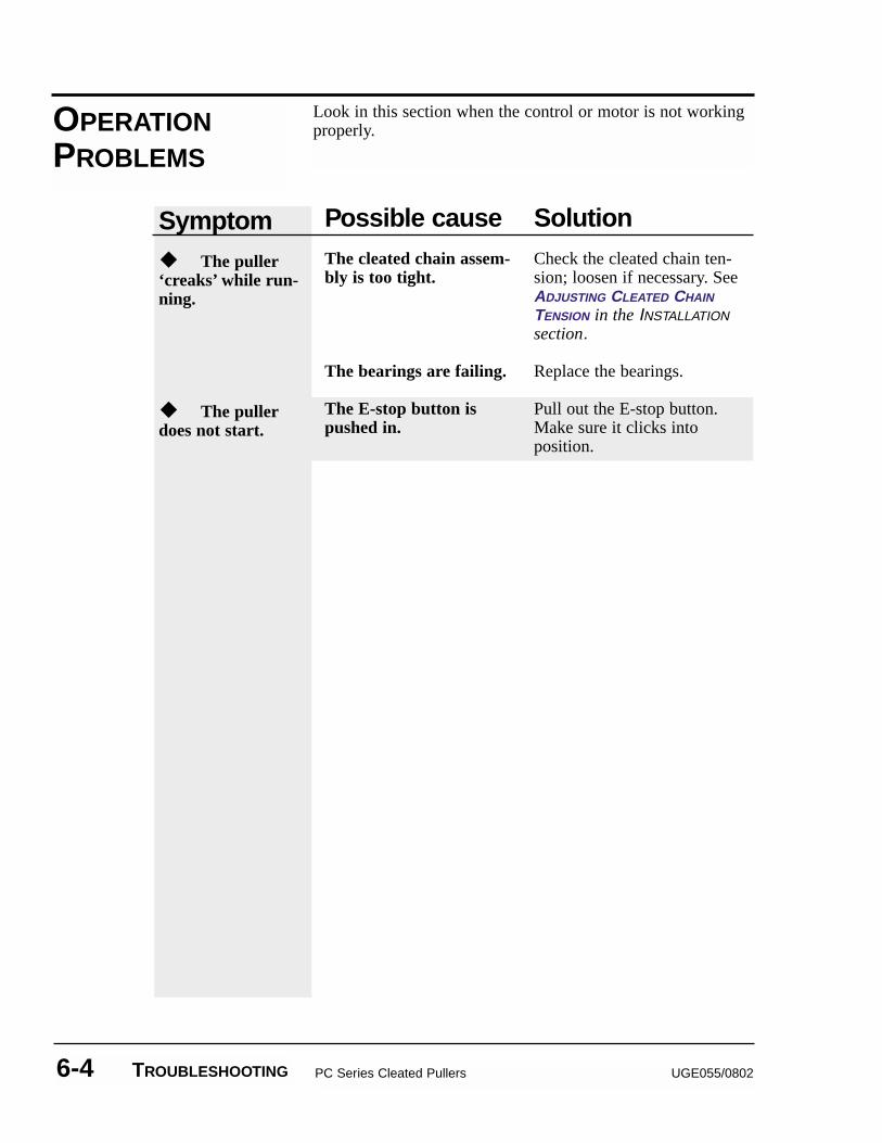
Look in this section when the control or motor is not workingproperly.
Symptom��The puller‘creaks’ while run-ning.
��The pullerdoes not start.
Possible causeThe cleated chain assem-bly is too tight.
The bearings are failing.
The E-stop button ispushed in.
SolutionCheck the cleated chain ten-sion; loosen if necessary. SeeADJUSTING CLEATED CHAIN
TENSION in the INSTALLATIONsection.
Replace the bearings.
Pull out the E-stop button.Make sure it clicks intoposition.
UGE055/0802 PC Series Cleated Pullers TROUBLESHOOTING 6-5
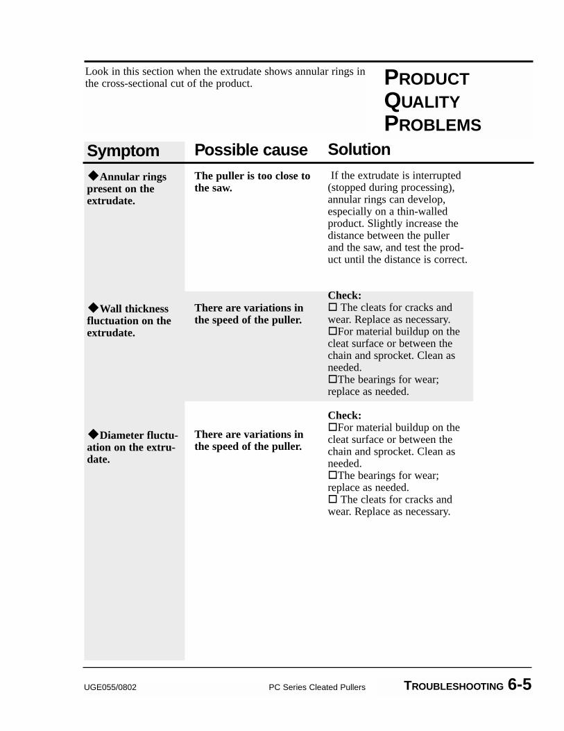
PRODUCTQUALITYPROBLEMS
Symptom�Annular ringspresent on theextrudate.
�Wall thicknessfluctuation on theextrudate.
�Diameter fluctu-ation on the extru-date.
Possible causeThe puller is too close tothe saw.
There are variations inthe speed of the puller.
There are variations inthe speed of the puller.
SolutionIf the extrudate is interrupted
(stopped during processing),annular rings can develop,especially on a thin-walledproduct. Slightly increase thedistance between the pullerand the saw, and test the prod-uct until the distance is correct.
Check:� The cleats for cracks andwear. Replace as necessary.�For material buildup on thecleat surface or between thechain and sprocket. Clean asneeded.�The bearings for wear;replace as needed.
Check:�For material buildup on thecleat surface or between thechain and sprocket. Clean asneeded.�The bearings for wear;replace as needed.� The cleats for cracks andwear. Replace as necessary.
Look in this section when the extrudate shows annular rings inthe cross-sectional cut of the product.
SERVICE INFORMATION APPENDIX A-1
Conair has made the largest investment in customer support inthe plastics industry. Our service experts are available to helpwith any problem you might have installing and operatingyour equipment. Your Conair sales representative also canhelp analyze the nature of your problem, assuring that it didnot result from misapplication or improper use.
To contact Customer Service personnel, call:
From outside the United States, call: 814-437-6861
You can commission Conair service personnel to provide on-site service by contacting the Customer Service Department.Standard rates include an on-site hourly rate, with a one-dayminimum plus expenses.
If you do have a problem, please complete thefollowing checklist before calling Conair:
� Make sure you have all model, serial and parts list numbersfor your particular equipment. Service personnel will needthis information to assist you.
� Make sure power is supplied to the equipment.
� Make sure that all connectors and wires within andbetween loading control and related components have beeninstalled correctly.
� Check the troubleshooting guide of this manualfor a solution.
� Thoroughly examine the instruction manual(s)for associated equipment, especially controls.Each manual may have its own troubleshootingguide to help you.
� Check that the equipment has been operated asdescribed in this manual.
� Check accompanying schematic drawings for information on special considerations.
BEFORE YOU
CALL ...
HOW TO CONTACT
CUSTOMER
SERVICE
Additional manuals andprints for your Conairequipment may beordered through theCustomer Service orParts Departments fora nominal fee.
WE’RE HERETO HELP
WARRANTY INFORMATIONAPPENDIX A-2
EQUIPMENTGUARANTEE
PERFORMANCEWARRANTY
WARRANTY
LIMITATIONS
Conair guarantees the machinery and equipment on thisorder, for a period as defined in the quotation from date ofshipment, against defects in material and workmanshipunder the normal use and service for which it was recom-mended (except for parts that are typically replaced afternormal usage, such as filters, liner plates, etc.). Conair’sguarantee is limited to replacing, at our option, the part orparts determined by us to be defective after examination.The customer assumes the cost of transportation of thepart or parts to and from the factory.
Conair warrants that this equipment will perform at orabove the ratings stated in specific quotations covering theequipment or as detailed in engineering specifications,provided the equipment is applied, installed, operated andmaintained in the recommended manner as outlined in ourquotation or specifications.
Should performance not meet warranted levels, Conair atits discretion will exercise one of the following options:
� Inspect the equipment and perform alterations oradjustments to satisfy performance claims. (Chargesfor such inspections and corrections will be waivedunless failure to meet warranty is due to misapplica-tion, improper installation, poor maintenance practicesor improper operation.)
� Replace the original equipment with other Conairequipment that will meet original performance claimsat no extra cost to the customer.
� Refund the invoiced cost to the customer. Credit issubject to prior notice by the customer at which time aReturn Goods Authorization Number (RGA) will beissued by Conair’s Service Department. Returnedequipment must be well crated and in proper operatingcondition, including all parts. Returns must be prepaid.
Purchaser must notify Conair in writing of any claim andprovide a customer receipt and other evidence that a claimis being made.
Except for the Equipment Guarantee and PerformanceWarranty stated above, Conair disclaims all other war-ranties with respect to the equipment, express orimplied, arising by operation of law, course of dealing,usage of trade or otherwise, including but not limited tothe implied warranties of merchantability and fitness fora particular purpose.
UGE055/0802 BELT ADJUSTMENT OPTIONS APPENDIX B-1
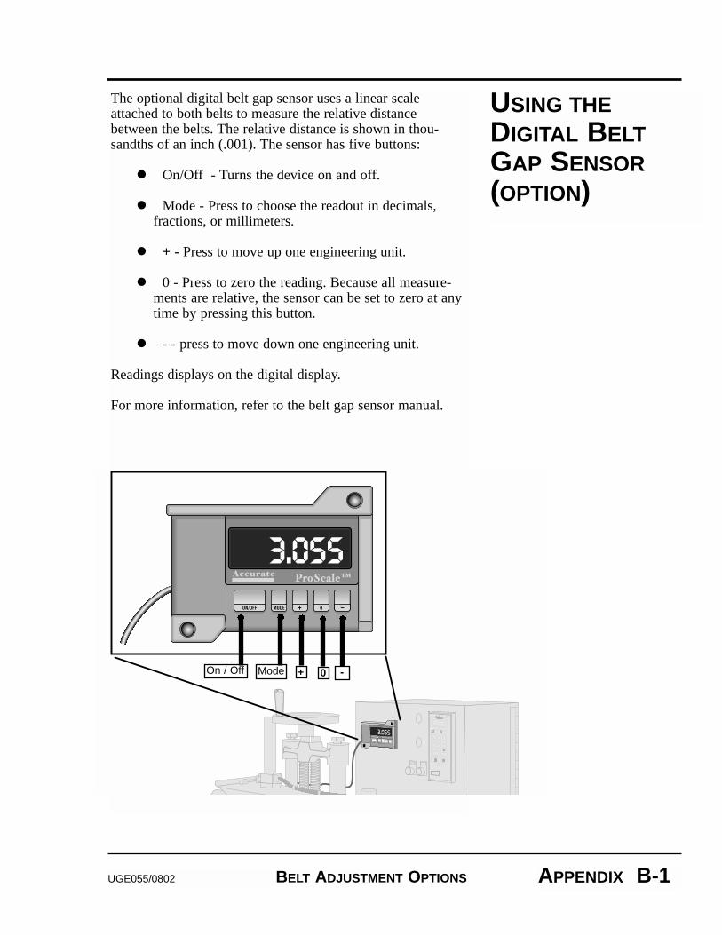
The optional digital belt gap sensor uses a linear scaleattached to both belts to measure the relative distancebetween the belts. The relative distance is shown in thou-sandths of an inch (.001). The sensor has five buttons:
��On/Off - Turns the device on and off.
��Mode - Press to choose the readout in decimals,fractions, or millimeters.
� + - Press to move up one engineering unit.
��0 - Press to zero the reading. Because all measure-ments are relative, the sensor can be set to zero at anytime by pressing this button.
��- - press to move down one engineering unit.
Readings displays on the digital display.
For more information, refer to the belt gap sensor manual.
USING THEDIGITAL BELTGAP SENSOR(OPTION)
On / Off Mode + 0 -