Embed Size (px)
Citation preview

8/7/2019 Payload 4(Part2)
http://slidepdf.com/reader/full/payload-4part2 1/133

8/7/2019 Payload 4(Part2)
http://slidepdf.com/reader/full/payload-4part2 2/133
Frequency Justification : NoJustification
� The frame rate of the STS SPE = the framerate of transport overhead ( OH; i.e., NE framerate)
� Then the alignment of the SPE is the same asthe previous frame.� NDF = 0110; I-bit / D-bit words are not
inverted.
� If pointer value = 0, the first byte of the data islocated next to the H3 byte;
� If pointer value = 10, the first byte starts on the11th byte after H3;
� Example=

8/7/2019 Payload 4(Part2)
http://slidepdf.com/reader/full/payload-4part2 3/133
STS-1: no frequency justification

8/7/2019 Payload 4(Part2)
http://slidepdf.com/reader/full/payload-4part2 4/133
Frequency Justification : PositiveJustification
� Frame rate of the STS SPE < the transport OH( i.e. NE frame rate )
� The alignment of the SPE is slipped back by a
byte.� H1, H2 incremtns and I-bits are inverted.� NDF = 0110� Example :
o I, D : value 00 0010 1010 = 40o First byte in SPE next to the H3 is 0o Positive justification is recognized quickly by
examining the bit next to the LSB of the H1 byte 1 : positive
0 : negative

8/7/2019 Payload 4(Part2)
http://slidepdf.com/reader/full/payload-4part2 5/133
STS-1 : positive-frequency justification

8/7/2019 Payload 4(Part2)
http://slidepdf.com/reader/full/payload-4part2 6/133
Frequency Justification :Negative Justification
� The frame rate of the STS SPE > thetransport OH (i.e., NE frame rate ).
� The alignment of the SPE is slipped back
by a byte� H1, H2 decrements� D-bit are inverted, NDF = 0110� Example :
o The I, D value is 00 0010 1000 = 40o H3 byte contains user payload in the current
frame.

8/7/2019 Payload 4(Part2)
http://slidepdf.com/reader/full/payload-4part2 7/133
STS-1 : negative frequency justification

8/7/2019 Payload 4(Part2)
http://slidepdf.com/reader/full/payload-4part2 8/133
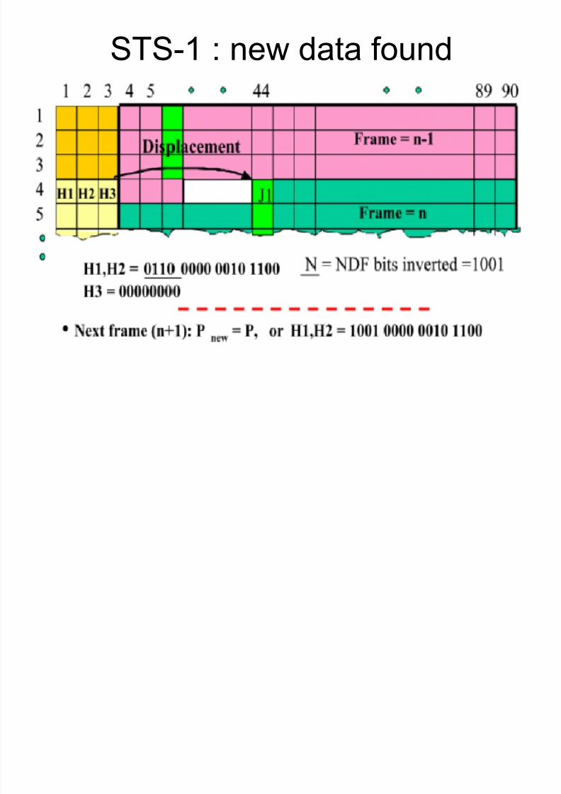
New Data Found ( example )
� NDF = 1001� A resynchronization has taken place ( not
due to a positive or negative frequency
justification but because of some system or payload-type change .
� I-bit and D-bit are not inverted� New pointer value in H1 and H2� For another case, known as concatenation
indicaiton :o NDF=1001o
I-bit and D-bit = 11 1111 1111
8/7/2019 Payload 4(Part2)
http://slidepdf.com/reader/full/payload-4part2 9/133
STS-1 : new data found

8/7/2019 Payload 4(Part2)
http://slidepdf.com/reader/full/payload-4part2 10/133
Path Overhead
� The first column of the SPE ( 9 bytes )� Path bytes are directional.� J1 : the trace byte , is user programmable
o The receiving PTE collects 64 repeating J1 bytes to verify theconnectivity with the transmitting PTE.
o Default : 0x00� BIP-8 or B3 : error control.� C2 : indicates the construction of SPE, the asynchronous mapping,
ATM, etc.� G1 : path status to the originating PTE from the destination PTE.� F2 : for end-user communication use.
� H4 : multiframe, is used as an end-to-end generalized multiframeindicator for payloads.
� Z3, Z4, Z5 : user bytes, reserved for future use and undefined for now.

8/7/2019 Payload 4(Part2)
http://slidepdf.com/reader/full/payload-4part2 11/133
SONET STS-1 : pathoverhead

8/7/2019 Payload 4(Part2)
http://slidepdf.com/reader/full/payload-4part2 12/133
SDH VC-3/4 : path overhead
8/7/2019 Payload 4(Part2)
http://slidepdf.com/reader/full/payload-4part2 13/133
5.2 SONET and SDH
Virtual Tributaries

8/7/2019 Payload 4(Part2)
http://slidepdf.com/reader/full/payload-4part2 14/133
Virtual Tributaries
� VT ( virtual tributary ) : small container thatis used to transport user payloads.
� In SDH, they are called VC ( virtual
containers ).� Each VT arrives within a 125 s interval.� Several VTs with OH ( overhead ) will
constitute an SPE.

8/7/2019 Payload 4(Part2)
http://slidepdf.com/reader/full/payload-4part2 15/133
Fig. 5.38 VTs : what are they ?

8/7/2019 Payload 4(Part2)
http://slidepdf.com/reader/full/payload-4part2 16/133

8/7/2019 Payload 4(Part2)
http://slidepdf.com/reader/full/payload-4part2 17/133
Table 5.7 Virtual Tributariesand Payload Rates
6.9127110812VT6
3.456142546VT3
2.304213364VT2
1.728284273VT1.5
VT payloadrates (Mbps)
VTs/SPEVTs/GroupBytes/VTColumns/VTVT Type

8/7/2019 Payload 4(Part2)
http://slidepdf.com/reader/full/payload-4part2 18/133
Fig. 5.39 Virtual tributaries
8/7/2019 Payload 4(Part2)
http://slidepdf.com/reader/full/payload-4part2 19/133
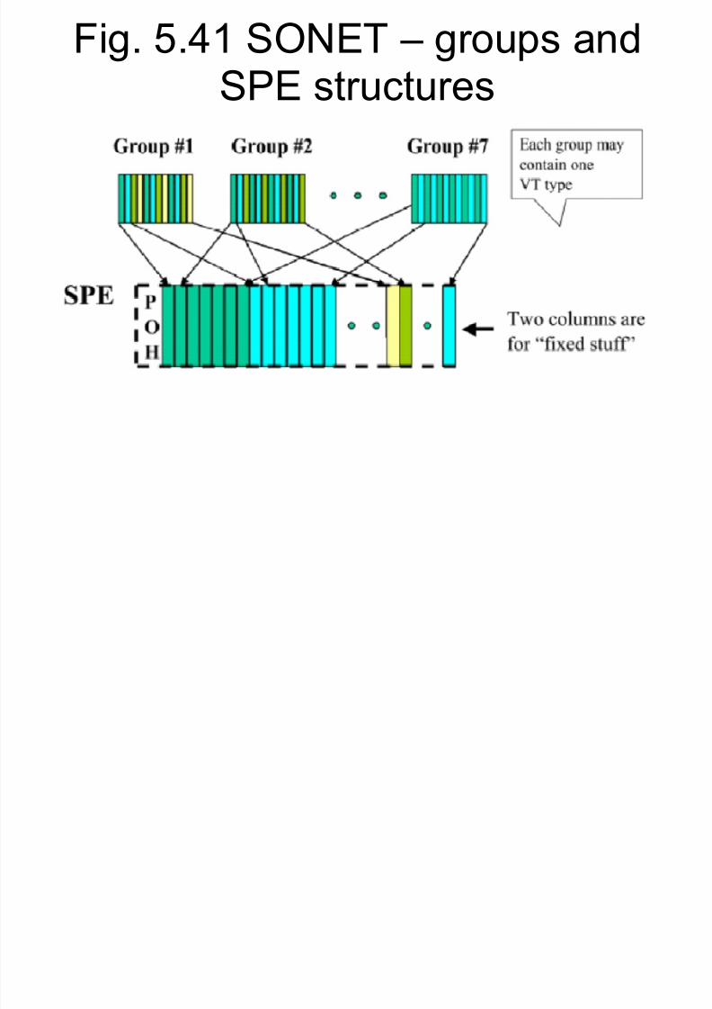
SPE Groups
� An STS-1 SPE contains 87 columns, thereal user payload is 84 columns.
� The payload is partitioned in 7 groups,
each group has 12 columns in capacity.� Each group can fit in 4 VT1.5 or 3 VT2 or 2
VT3 or 1 VT4.� Different groups can have different types of
VTs� Each group can have only one type of VT.� In SDH, groups are called TUG-2 ( tributary
unit group ).

8/7/2019 Payload 4(Part2)
http://slidepdf.com/reader/full/payload-4part2 20/133
SPE Groups
� When VTs form one SPE group, they arebyte-interleaved.
� Each SPE group can have only one kind of
VT.� The 7 SPE groups form SPE by byte ( or
column ) interleaving� The fixed stuffs columns and the path
overhead column are also byte interleavedto construct the SPE.

8/7/2019 Payload 4(Part2)
http://slidepdf.com/reader/full/payload-4part2 21/133
Fig. 5.40 SONET ± VTs andgroup structures tributaries
8/7/2019 Payload 4(Part2)
http://slidepdf.com/reader/full/payload-4part2 22/133
Fig. 5.41 SONET ± groups andSPE structures
8/7/2019 Payload 4(Part2)
http://slidepdf.com/reader/full/payload-4part2 23/133
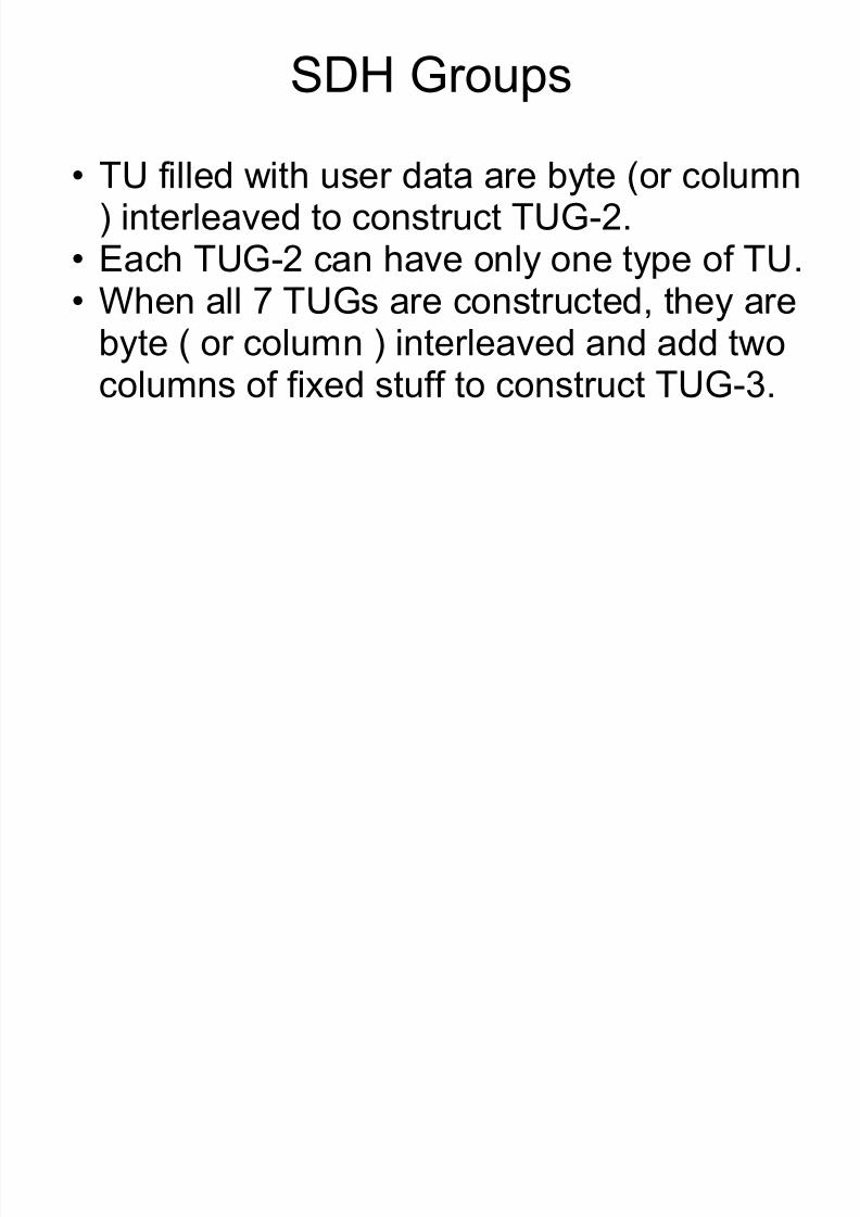
SDH Groups
� TU filled with user data are byte (or column) interleaved to construct TUG-2.
� Each TUG-2 can have only one type of TU.
� When all 7 TUGs are constructed, they arebyte ( or column ) interleaved and add twocolumns of fixed stuff to construct TUG-3.

8/7/2019 Payload 4(Part2)
http://slidepdf.com/reader/full/payload-4part2 24/133
Fig. 5.42 SDH ± TU and TUGstructures

8/7/2019 Payload 4(Part2)
http://slidepdf.com/reader/full/payload-4part2 25/133
Fig. 5.43 SDH -- TUGs

8/7/2019 Payload 4(Part2)
http://slidepdf.com/reader/full/payload-4part2 26/133
Fig. 5.44 VT1.5 mapping inSPE

8/7/2019 Payload 4(Part2)
http://slidepdf.com/reader/full/payload-4part2 27/133
VT Superframe
� VTs map data from different end users in theSPE payload.o End user data may also be out of phase with each
other and to the STS-N frame.o A pointer and a frequency justification scheme,
similar to the SPE level, applies on the VT level.
� Each VT is partitioned in a 1-byte VT overheadpart and in a VT envelope capacity ( depending
on the type of VT ).o VT1.5 : 26 bytes VT envelope capacityo VT6 : 107 bytes VT envelope capacity
� 4 consecutive VTs from one user¶s data form a
VT superframe.

8/7/2019 Payload 4(Part2)
http://slidepdf.com/reader/full/payload-4part2 28/133
VT Superframe
� Payloads below DS3 rates are mapped in andtrasported by VT structures.
� H4 in the SPE path overhead is used to
indicate the phase of V1-V4 ( bits B7 and B8 )as well as 6-, 16-, or 24-frame superframeindication ( bits B1 and B2 or B3 and B4 or B5and B6 )o
To comply with Bellcore ( AR-254-CORE ), thefollowing rules apply to H4 bits : X is set to ³1´ or Bits B1 and B2 count from 00 through 11 over 24 frames or Bits B3 and B4 count from 00 through 01 over 6 frames
and then repeat or Bits B5 and B6 countr from 00 through 11 over 16 frames

8/7/2019 Payload 4(Part2)
http://slidepdf.com/reader/full/payload-4part2 29/133
Fig. 5.45 VT superframe

8/7/2019 Payload 4(Part2)
http://slidepdf.com/reader/full/payload-4part2 30/133
Fig. 5.46 VT superframe ± H4byte
V4XXXXXX 1 1
V3XXXXXX 1 0
V2XXXXXX 0 1
V1XXXXXX 0 0
V1 ± V4H4 BYTE1 2 3 4 5 6 7 8

8/7/2019 Payload 4(Part2)
http://slidepdf.com/reader/full/payload-4part2 31/133

8/7/2019 Payload 4(Part2)
http://slidepdf.com/reader/full/payload-4part2 32/133

8/7/2019 Payload 4(Part2)
http://slidepdf.com/reader/full/payload-4part2 33/133
Fig. 5.48 VT payload pointer --NDF

8/7/2019 Payload 4(Part2)
http://slidepdf.com/reader/full/payload-4part2 34/133
Fig. 5.49 VT payload pointer --value

8/7/2019 Payload 4(Part2)
http://slidepdf.com/reader/full/payload-4part2 35/133
VT Payload Pointer
� Frequency adjustment is made by slippingby a byte forwand or back in time the VTenvelope.
o Similar to the STS SPE frequency justifications.� The increment or decrement amount is
indicated by inverting the I-bit or D-bit word,respectively.
� When the frame rate of the VT envelope isgreater than or less than that of the STSSPE, the alignment of the VT envelope is
periodically slipped forward or backward in

8/7/2019 Payload 4(Part2)
http://slidepdf.com/reader/full/payload-4part2 36/133
VT Overhead
� The first byte in the envelope.� Over four frames, or 500 s, the four
overhead bytes are V5, J2, Z6 and Z7.
� The remaining bytes in a VT are user payload.
� For VT1.5, the� user payload is 25 bytes.
� For VT6, the user payload is 106 bytes.� Each VT envelope contains four bytes of
VT POH ( V5, J2, Z6 and Z7 ), the
remaining bytes are VT payload capacity.
Fi 0 Vi l ib i

8/7/2019 Payload 4(Part2)
http://slidepdf.com/reader/full/payload-4part2 37/133
Fig. 5.50 Virtual tributariesoverhead

8/7/2019 Payload 4(Part2)
http://slidepdf.com/reader/full/payload-4part2 38/133
VT Overhead
� V5 : the first POH byte in the VT superframeo Error checking as a signal labelo Indicating the signal status
� Bits in V5 are :o BIP-2 (1) : set if parity of all odd-numbered bits of previous VT SPE
is eveno BIB-2 (2) : set if parity of all eveb-numbered bits of previous VT
SPE is eveno REI-V : VT remote error indication back to originating VT PTE.o RFI-V : VT path remote failure indication in byte-synchronous DS1
mapping.
o Signal label : indicates content of the VT SPE.o RDI-V : VT path remote defect indication.

8/7/2019 Payload 4(Part2)
http://slidepdf.com/reader/full/payload-4part2 39/133
Fig. 5.51 Virtual tributaries pathoverhead

8/7/2019 Payload 4(Part2)
http://slidepdf.com/reader/full/payload-4part2 40/133
Application : DS0 bytesynchronous Mapping For DS1
� In a DS1 frame, there are 24 time slots(bytes ).
� Mapping one DS1 in a VT1.5.
� User payload in a VT1.5 has 25 bytes, thefirst byte haso The phase of the signaling and the frame bits
(bits P0 and P1)
o Signaling for the 24 DS0 channels ( bits S1-S4 )o The framing bit ( bit F )o A bit not used ( or fixed stuff )
� The remaining 24 bytes map the 24 bytes
of the DS1 frame.

8/7/2019 Payload 4(Part2)
http://slidepdf.com/reader/full/payload-4part2 41/133
Fig. 5.52 VT1.5 DS0 byte ±synchronous mapping in Ds1
S

8/7/2019 Payload 4(Part2)
http://slidepdf.com/reader/full/payload-4part2 42/133
Application : DS0 Byte- Asynchronous Mapping for DS1
� A DS1 frame consists of 24 time slots� User payload in a VT1.5 has 25 bytes, the
first byte has
o Fixed stuff ( bits R )o Information bits ( bit 1 )o Stuff control bits ( bits C1 and C2 )o Overhead bits ( bit O )o
Stuff opportunity ( bits S )� The remaining 24 bytes map the 24 bytesof the DS1 frame.
Fi 5 53 VT1 5 DS0 b

8/7/2019 Payload 4(Part2)
http://slidepdf.com/reader/full/payload-4part2 43/133
Fig. 5.53 VT1.5 DS0 byte ±synchronous mapping in Ds1

8/7/2019 Payload 4(Part2)
http://slidepdf.com/reader/full/payload-4part2 44/133
5.2 SONET and SDH
STS-N/STM-N Frames

8/7/2019 Payload 4(Part2)
http://slidepdf.com/reader/full/payload-4part2 45/133
Single-Step Multiplexer
� A multiplexer that receives N STS-1 SPEswithin a time window and then in one singlestage to multiplex them to produce an STS-
N.� The basic building block ( signal ) for STS-
N frames are STS-1 SPE when N > 1.� Multiplexing is on the byte level.
Fi 5 54 STS N i l t

8/7/2019 Payload 4(Part2)
http://slidepdf.com/reader/full/payload-4part2 46/133
Fig. 5.54 STS-N single-stageinterleaving.

8/7/2019 Payload 4(Part2)
http://slidepdf.com/reader/full/payload-4part2 47/133
Two-Step Multiplexer
� Two-step multiplexing : K STS-1 SPEs maybe received and multiplexed in an STS-Kand then N/K STS-Ks multiplexed to
produce an STS-N.� Multiplexing is on the byte level.� Two-step multiplexing is more complicated
than one-step multiplexing.
� Two-step multiplexing also creates moredelay ( because there are more steps inmultiplexing ) than one-step multiplexing.
Fig 5 55 STS N t o stage

8/7/2019 Payload 4(Part2)
http://slidepdf.com/reader/full/payload-4part2 48/133
Fig. 5.55 STS-N two-stageinterleaving.

8/7/2019 Payload 4(Part2)
http://slidepdf.com/reader/full/payload-4part2 49/133
STS-N Frame Structure
� Each STS-N frame has Nx90 columns and 9rows.
� Overhead ( line, section ) : the first Nx3columns
� Each STS-N SPE has Nx783 bytes� The first N columns of an STS-N SPE are the
path overhead
� For exampleo For an STS-3 frame, has a total of 3x90 = 270
columns by 9 rows.o Line & section overhead are the first 3x3 = 9
columnso Each STS-3 SPE has 3x783 = 2249 bytes
Fig 5 56 STS N frame

8/7/2019 Payload 4(Part2)
http://slidepdf.com/reader/full/payload-4part2 50/133
Fig. 5.56 STS-N framestructure.
8/7/2019 Payload 4(Part2)
http://slidepdf.com/reader/full/payload-4part2 51/133
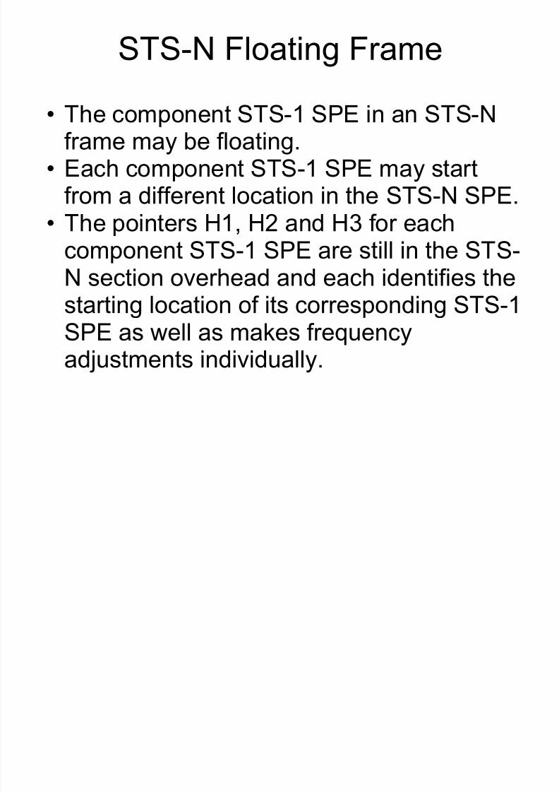
STS-N Floating Frame
� The component STS-1 SPE in an STS-Nframe may be floating.
� Each component STS-1 SPE may start
from a different location in the STS-N SPE.� The pointers H1, H2 and H3 for each
component STS-1 SPE are still in the STS-N section overhead and each identifies the
starting location of its corresponding STS-1SPE as well as makes frequencyadjustments individually.
Fig 5 57 STS N example N =

8/7/2019 Payload 4(Part2)
http://slidepdf.com/reader/full/payload-4part2 52/133
Fig. 5.57 STS-N example, N =3.

8/7/2019 Payload 4(Part2)
http://slidepdf.com/reader/full/payload-4part2 53/133
Concatenation or Super-Rate
� For example of STS-3� If 3 STS-1 SPEs are from different sources and
each one may be in different phases with eachother and with the node, each will keep its own
ponter H1-H3 and frequency justification.� If 3 SPS-1 SPEs are belong to the SAME signal
source, and they arrive in a specific order and insynchronism ( which must be maintained throughout
the end-to-end path .), these will be processed intoconcatenated SPEs.
� The 3 SPEs are mapped in a known sequence andthus only one overhead pointer is required to pointto the first SPE.
� The remainin ointers contain a fixed code set to a

8/7/2019 Payload 4(Part2)
http://slidepdf.com/reader/full/payload-4part2 54/133
Concatenation or Super-Rate
� Also, only one path overhead is needed.� At the receiving end, all 3 SPEs are
received in the same order they were
transmitted.� The STS that transports concatenated
SPEs is called concatenated STS, denotedby STS-Nc ( in this case, STS-3c ).
� Similar case for N > 3.
Fig 5 58 STS Nc example N

8/7/2019 Payload 4(Part2)
http://slidepdf.com/reader/full/payload-4part2 55/133
Fig. 5.58 STS-Nc example, N = 3.
Contiguous Concatenation in

8/7/2019 Payload 4(Part2)
http://slidepdf.com/reader/full/payload-4part2 56/133
Contiguous Concatenation inSDH
� Allows bit rates in excess of the capacity of theC-4 container.
� Concatenation implies that payload should notbe split up
� A virtually contiguous container within an STM-4 ( for example ).
� Then the payload of several consecutive AU-
4¶s are mapped in a fixed order.� The first pointer is set to its value and the restpointers are set to a fixed CI value.
� This VC-4 is identified as a VC-4-4c.

8/7/2019 Payload 4(Part2)
http://slidepdf.com/reader/full/payload-4part2 57/133
Virtual Concatenation
� Some network (switching) nodes are notcapable of switching complete STS-3c or VC-4-4c with contiguously concatenated
payload in them.� Then these payload will be split into
payloads of lower rate, like STS-1 andeach STS-1 will be switched independently.
� The responsibility of reconstruct the STS-1¶s back to the original STS-3c is on thenetwork elements.

8/7/2019 Payload 4(Part2)
http://slidepdf.com/reader/full/payload-4part2 58/133
Fig 5 59 STM N frame

8/7/2019 Payload 4(Part2)
http://slidepdf.com/reader/full/payload-4part2 59/133
Fig. 5.59 STM-N framestructure.

8/7/2019 Payload 4(Part2)
http://slidepdf.com/reader/full/payload-4part2 60/133
STS-Nc Frame Structure
� The major difference between STS-N andSTS-Nc payload : then number of pathoverhead column in the SPE.o
For STS-N : N columnso For STS-Nc : 1 column
� The difference in the fixed-stuff columnso For STS-N : 2N columnso
For STS-Nc : N/3 -1 columns� STS-Nc has more bandwidth for dedicateduser payload and more efficient.
Fig 5 60 STS Nc frame

8/7/2019 Payload 4(Part2)
http://slidepdf.com/reader/full/payload-4part2 61/133
Fig. 5.60 STS-Nc framestructure.

8/7/2019 Payload 4(Part2)
http://slidepdf.com/reader/full/payload-4part2 62/133
Fig 5 61 STS-3c transport
8/7/2019 Payload 4(Part2)
http://slidepdf.com/reader/full/payload-4part2 63/133
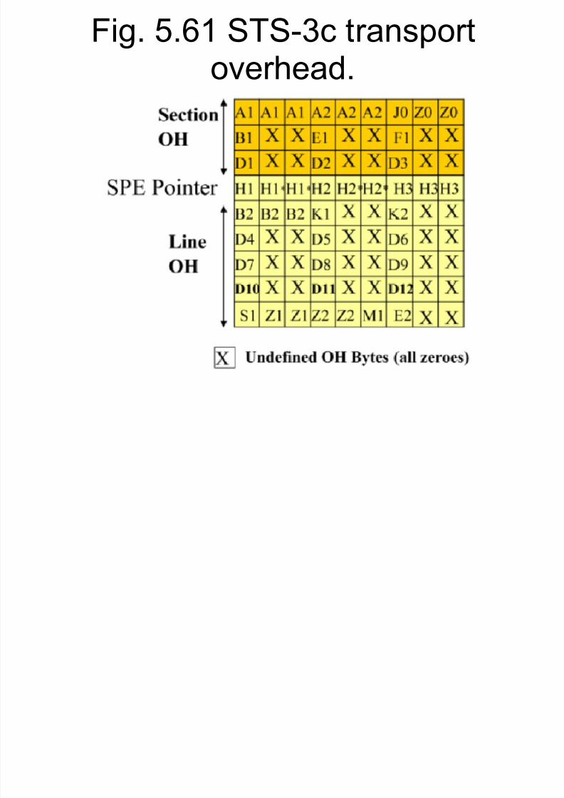
Fig. 5.61 STS-3c transportoverhead.
Transport Overhead : SOH for

8/7/2019 Payload 4(Part2)
http://slidepdf.com/reader/full/payload-4part2 64/133
Transport Overhead : SOH for SDH
� A1, A2 : frame alignment; fixed framing pattern set at the hexadecimalvalue 0xF628 [ 1111 0110 0010 1000 ].o A1, A2 are NOT scrambled.
� B1, B2 : parity bytes for quality monitoring ( or error monitoring inSONET ).o The parity is calculated over ALL bytes of the previous frame before
scrambling and is placed in the current frame before scrambling.� D1 ± D3 : for network management for the regenerator section
o An 192 Kbps communication channels for alarms, maintenance,control, monitoring, administration, and other needs.
� D4 ± D12 : for network management as the D1 ± D3 but for themultiplex section.
� E1, E2 : a 64 Kbps voice communication channel for craft personnel.� F1 : a maintenance byte� J0 ( C1 ) : trace identifier
Transport Overhead : SOH for
8/7/2019 Payload 4(Part2)
http://slidepdf.com/reader/full/payload-4part2 65/133
Transport Overhead : SOH for SDH
� K1, K2 : for automatic protection switching ( APS ) control
� S1 : clock quality indicator
� M1 : transmission error acknowledgement
Fig 5 62 STM-1 section

8/7/2019 Payload 4(Part2)
http://slidepdf.com/reader/full/payload-4part2 66/133
Fig. 5.62 STM-1 sectionoverhead.

8/7/2019 Payload 4(Part2)
http://slidepdf.com/reader/full/payload-4part2 67/133
Scrambling
� When the complete frame has beenassembled, the bytes in it are scrambled.
� Purpose : to assure the receiver that a
density of 1¶s is maintained in the signal.� A1, A2, C1 bytes are not scrambledo A1 and A2 are used to locate the beginning of
the frame, so no scrambling are applied

8/7/2019 Payload 4(Part2)
http://slidepdf.com/reader/full/payload-4part2 68/133
Fig. 5.63 Frame scrambled.

8/7/2019 Payload 4(Part2)
http://slidepdf.com/reader/full/payload-4part2 69/133
STS-N Scrambler
� The scrambling code is generated by thepolynomial 1 + x6 + x7
� The scrambler is frame synchronous at the linerate ( STS-N ), and it has a sequence length of 127 bits that repeats itself.
� The scrambler is set to 1111111 on the mostsignificant bit ( MSB ) of the byte following theNth STS-1 C1 byte ( of an STS-N )
� The framing bytes A1, A2 and C1 from the firstSTS-1 through the Nth STS-1 are NOTscrambled.
� The scrambler runs continuously throughout
S S

8/7/2019 Payload 4(Part2)
http://slidepdf.com/reader/full/payload-4part2 70/133
Fig. 5.64 STS-N scrambler.
Layered Overhead and Transport

8/7/2019 Payload 4(Part2)
http://slidepdf.com/reader/full/payload-4part2 71/133
Layered Overhead and TransportFunction
� How to transport traditional signals, such as DS1, E1, etc. with aSONET signal ?
� To transport a DS1 signal to a SONET signal :o The incoming DS1 signal at the path layer is mapped onto a VT.o The VT is mapped onto the SPE, and the SPE path overhead is
also constructed.o The SPE is mapped onto the SONET signal, and the line overhead
information is added.o The signal is mapped onto the STS-N signal, and the section
overhead information is added. Now the complete STS SONET signal is formed, and the signal is
scrambled.
o The signal passed through the electrical-to-optical transducer ( thetransmitter ), and the optical signal ( with an NRZ optical coding ) iscoupled into the optical fiber and transmitted at the speed of light.
Fig. 5.65 Conversion of a legacy signal to a

8/7/2019 Payload 4(Part2)
http://slidepdf.com/reader/full/payload-4part2 72/133
SONET, layered overhead and transportfunctions.
I t ti B t L

8/7/2019 Payload 4(Part2)
http://slidepdf.com/reader/full/payload-4part2 73/133
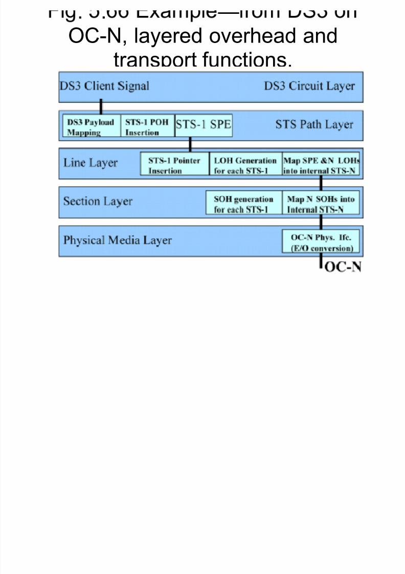
Interaction Between Layers
� SONET signal is transmitted between NEs� Similar layers of the SONET signal, as
viewed between the transmitting and
receiving NEs, interact at thecorresponding layers.
. . ²OC N l d h d d
8/7/2019 Payload 4(Part2)
http://slidepdf.com/reader/full/payload-4part2 74/133
OC-N, layered overhead andtransport functions.
. .l l d h d d

8/7/2019 Payload 4(Part2)
http://slidepdf.com/reader/full/payload-4part2 75/133
layers, layered overhead andtransport functions.
SDH M lti l i

8/7/2019 Payload 4(Part2)
http://slidepdf.com/reader/full/payload-4part2 76/133
SDH Multiplexing
� SDH follows a very similar hierarchicalmultiplexing scheme to SONET
� Traditional signals are mapped onto
containers, the containers are multiplexedinto groups, and overhead is added toconstruct an STM-N signal. ( CCITTRecommendation G.907 )
Fig. 5.68 SONET multiplexing

8/7/2019 Payload 4(Part2)
http://slidepdf.com/reader/full/payload-4part2 77/133
Fig. 5.68 SONET multiplexingscheme.
Fig. 5.69 SDH multiplexing

8/7/2019 Payload 4(Part2)
http://slidepdf.com/reader/full/payload-4part2 78/133
Fig. 5.69 SDH multiplexingscheme.

8/7/2019 Payload 4(Part2)
http://slidepdf.com/reader/full/payload-4part2 79/133
5.2 SONET and SDH
Synchronization and Timing
N t k S h i ti

8/7/2019 Payload 4(Part2)
http://slidepdf.com/reader/full/payload-4part2 80/133
Network Synchronization
� On a network, from a receiving node pointof reference, all signals are received atdifferent phases with its clock and frame
synchronization.� The phase difference could be easilyengineered if it would remian fixed or bounded;o Received signals can be aligned if the phase
difference is fixed.o A fixed phase also implies all nodes are exactly
operate at the same frequency.
� But NEs are not exactly using the SAME
N t k S h i ti

8/7/2019 Payload 4(Part2)
http://slidepdf.com/reader/full/payload-4part2 81/133
Network Synchronization
� In practical, a small difference between theclocks from node to node may result in asubstantial frequency variation as the
signal passed through many nodes.� The problem can be solved if a commontiming source can be established
� The network uses a frequency of extremely
high accuracy from a timing service knownas Building Information Timing Supply (BITS ) in North America
� In Europe, the similar standard to BITS is
Fig. 5.70 Network

8/7/2019 Payload 4(Part2)
http://slidepdf.com/reader/full/payload-4part2 82/133
gsynchronization²a model.
Timing Accuracy : Strata

8/7/2019 Payload 4(Part2)
http://slidepdf.com/reader/full/payload-4part2 83/133
Timing Accuracy : Strata
� The timing architecture in the communicationsnetwork is hierarchical.
� Each node in the network is required to main afrequency accuracy and depends on its major function in the network for timing accuracy ( if other nodes in the network depend on it for timing accuracy).
� The highest possible frequency accuracy is 10x 10-11
o Highly accurate atomic clockso The clock will be the PRS and the accuracy is
referred as stratum 1.o Stratum 1 accuracy allows a slip up to 2.523
Timing Accuracy : Strata

8/7/2019 Payload 4(Part2)
http://slidepdf.com/reader/full/payload-4part2 84/133
Timing Accuracy : Strata
� Stratum 2 : 1.6 x 10⁻⁸
� Stratum 3 : 4.6 x 10⁻⁶
� Stratum 4 : 3.2 x 10⁻⁵
o
For example, the digital PRX
s, central officeterminals, and digital channel banks.
� In SDH, PRS is called primary referenceclock ( PRC )o
Accuracy 1.0 x 10⁻¹¹
o The clock is distributed throughout the entirenetwork
o Regenerated at the NEs by a synchronization
supply unit ( SSU ) and also by a synchronous
Table 5 8 Timing Accuracy

8/7/2019 Payload 4(Part2)
http://slidepdf.com/reader/full/payload-4part2 85/133
Table 5.8 Timing Accuracy
DCB/COT/DPBX15.36 / minute3.2×10-54
e.g. 5ESS/DCS132.48 / hour 4.6×10-63
e.g., 4ESS/5ESS11.06 / day1.6×10-82
PRS2.523 / year 10×10-111
NotesSkip RateMinimum Accuracy
Stratum
Timing Stability

8/7/2019 Payload 4(Part2)
http://slidepdf.com/reader/full/payload-4part2 86/133
Timing Stability
� Since signal may pass through parts of networkowned by more than one provider
� SONET NEs must be synchronized with astratum 3 or better quality clock.
� Or, SONET NEs can equipped with an internalclock ( oscillator ) that has a minimum accuracyof 20 parts per million ( ppm ).o This is required to support operation,
administration, maintenance, and provisioning (OAM&P ) functionality of all nodes in the network.
o Network providers must also supply a timingreference signal that meets the recommended
stability requirements.

8/7/2019 Payload 4(Part2)
http://slidepdf.com/reader/full/payload-4part2 87/133
BITS Timing Model

8/7/2019 Payload 4(Part2)
http://slidepdf.com/reader/full/payload-4part2 88/133
BITS Timing Model
� Where BITS ( or SASE ) is available, the NEsare externally timed from it.o The same quality reference clock over two paths,
the active and the alternate, are supplied by BITS.o The NE receives both signals, but it operates from
the active path.o If the active path goes down, the NE selects the
alternate clock.o
NE¶s time unit ( TU ) Receiving the two clocks from BITS Monitoring the incoming clocks for faults Selecting the correct ones Distributes the clock to all functional units in the NE
Fig. 5.71 BITS network

8/7/2019 Payload 4(Part2)
http://slidepdf.com/reader/full/payload-4part2 89/133
gsynchronization.

8/7/2019 Payload 4(Part2)
http://slidepdf.com/reader/full/payload-4part2 90/133
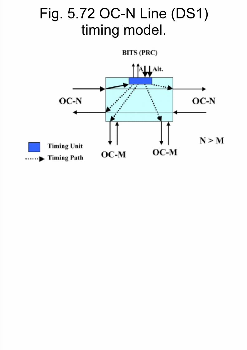
Fig. 5.72 OC-N Line (DS1)
8/7/2019 Payload 4(Part2)
http://slidepdf.com/reader/full/payload-4part2 91/133
g ( )timing model.
OC-M Single DS1 Line Timing

8/7/2019 Payload 4(Part2)
http://slidepdf.com/reader/full/payload-4part2 92/133
Model
� The NE extracts an 8-KHz clock from anincoming signal, typically a DS1 that isembedded in an incoming OC-M ( N > M)
signal.� The extracted 8 KHz is sent to TU, thensent to BITS over two separate paths.
� The BITS retimed and sent it back to the
NE over the active and alternate paths.� The TU distributes the retimed reference
clock to all functional units in the NE.
Fig. 5.73 OC-M Line (DS1)

8/7/2019 Payload 4(Part2)
http://slidepdf.com/reader/full/payload-4part2 93/133
timing model.
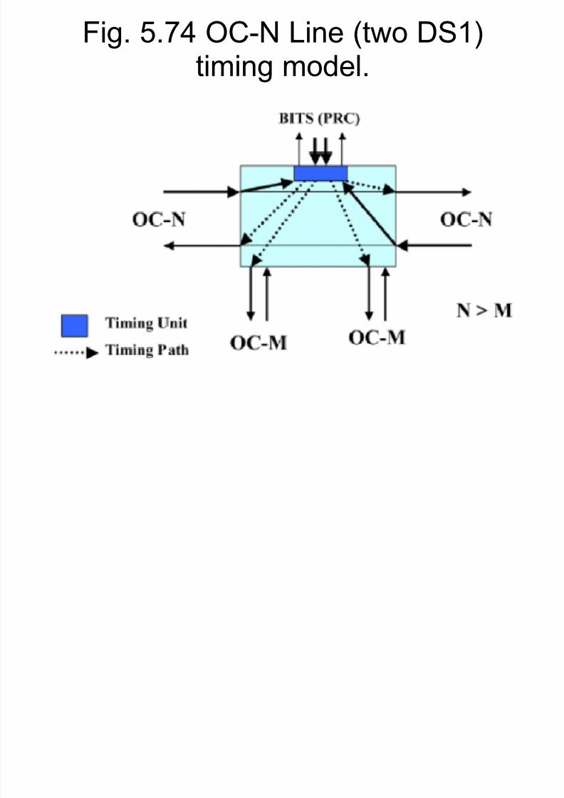
OC-N Dual-DS1 Line Timing

8/7/2019 Payload 4(Part2)
http://slidepdf.com/reader/full/payload-4part2 94/133
Model
� The NE extracts two independent clocksfrom two OC-N incoming signals.
� The two incoming OC-Ns are used to
extract from DS1¶s two 8-KHzsynchronization signals.� The extracted 8 KHz is sent to TU, then
sent to BITS over two separate paths.
� The BITS retimed and sent it back to theNE over the active and alternate paths.
� The TU distributes the retimed referenceclock to all functional units in the NE.
Fig. 5.74 OC-N Line (two DS1)
8/7/2019 Payload 4(Part2)
http://slidepdf.com/reader/full/payload-4part2 95/133
timing model.
Loop Timing Model

8/7/2019 Payload 4(Part2)
http://slidepdf.com/reader/full/payload-4part2 96/133
Loop Timing Model
� The NE is not connected to a BITS.� The NE is connected to only one OC-N and to
lower bit rate OC-M ( N > M ) and DS-N.� The NE extracts the clock from incoming
signals of the loop, typically a DS1.� An incoming OC-N is used to extract an 8-KHz
synchronization signal.� The extracted 8 KHz is sent to TU, .� The TU retimed the clock based on an
accurate phase-locked loop oscillator, locatedon the TU and then distributes it to allfunctional units in the NE.
Fig 5 75 Loop timing model

8/7/2019 Payload 4(Part2)
http://slidepdf.com/reader/full/payload-4part2 97/133
Fig. 5.75 Loop timing model.
Through-Timing Model

8/7/2019 Payload 4(Part2)
http://slidepdf.com/reader/full/payload-4part2 98/133
Through-Timing Model
� This model applies to regenerator elements.
� Each direction has its own TU and timing is
extracted from each direction.� This model is not recommended for add-drop multiplexers.
Fig. 5.76 Through-timing

8/7/2019 Payload 4(Part2)
http://slidepdf.com/reader/full/payload-4part2 99/133
model.
Clock Applications

8/7/2019 Payload 4(Part2)
http://slidepdf.com/reader/full/payload-4part2 100/133
Clock Applications
� The minimum free-running accuracy of a SONET minimum clock (SMC ) shall be 20 ppm.
� An ADM could be timed from a clock extracted from a line or from anexternal clock sources, or though-timed.o A holdover : when the reference clock fails, then for a specified
limited period of time, it enters a free-running state with a specified
tolerance.� A switched digital module in terminal mode ( TM ) configuration and
loop-timed may be required to provide holdover.� A digital cross-connect system with external timing is required with a
minimum accuracy of 4.6 ppm.� Entry into holdover and restoration from holdover shall be error free.

8/7/2019 Payload 4(Part2)
http://slidepdf.com/reader/full/payload-4part2 101/133
5.2 SONET and SDH
Maintenance
Maintenance

8/7/2019 Payload 4(Part2)
http://slidepdf.com/reader/full/payload-4part2 102/133
Maintenance
� Anomaly : a discrepancy between the actualand desired characteristics of an item.
� Defect : a limited interruption in the ability of anitem to perform a required function.
� Failure : a persistent defect. An NE enters afailure state when a failure condition has beendetected, and it exits a failure state when thecondition has been corrected.
� Maintenance of a system defineso The functions to be monitoredo The requirementso The criteriao Their parameters
Maintenance
8/7/2019 Payload 4(Part2)
http://slidepdf.com/reader/full/payload-4part2 103/133
Maintenance
� Performance of a function :o Acceptableo Unacceptable ( failed )o Degraded
� Main objectives of maintenance :o Trouble detectiono Trouble sectionalizationo Trouble or repair verificationo Trouble isolationo Restoration
Maintenance

8/7/2019 Payload 4(Part2)
http://slidepdf.com/reader/full/payload-4part2 104/133
Maintenance
� Maintenance requirementso Alarm surveillanceo Performance monitoring ( PM )o Control
Alarm Surveillance

8/7/2019 Payload 4(Part2)
http://slidepdf.com/reader/full/payload-4part2 105/133
Alarm Surveillance
� Alarm surveillance deals with the detection andreporting of certain failures and degradedconditions in the network.
� NE alarm surveillance takes place on different
levels, at :o Section terminating equipment ( STE )o Line terminating equipment ( LTE )o STS path terminating equipment ( STS PTE )
o VT path terminating equipment ( VT PTE )� A VT PTE contains all functionality of an STE,
LTE and STS PTE.� An STS PTE has all the functionality of an LTE
and STE.
Fig. 5.77 Maintenance: layeredl ill

8/7/2019 Payload 4(Part2)
http://slidepdf.com/reader/full/payload-4part2 106/133
alarm surveillance.
Alarm Indications

8/7/2019 Payload 4(Part2)
http://slidepdf.com/reader/full/payload-4part2 107/133
Alarm Indications
� A change of state may cause an alarmindication immediately as it occurs or after some period of time.
� When a failure state is detected, an alarmindication signal ( AIS ) is constructed andit is sent to the next NE on the downstreampath.o AIS is to alert downstream equipment of an
upstream failure.o The response to a received AIS is a remote
defect indication ( RDI ) signal in the upstream
direction
Alarm States, Declarations, andI di ti

8/7/2019 Payload 4(Part2)
http://slidepdf.com/reader/full/payload-4part2 108/133
Indications
� Loss of signal ( LOS ) : no light pulses persistfor 100 s.o If light pulses are lost for less than 2.3 s, then no
LOS is declared.
o However, if they persist for a period longer than 2.5sec, then an alarm message is sent to theoperating system ( OS ).
� Loss of frame ( LOF ) : a severely erroneous
frame ( SEF ) persists for a period longer than3 ms.o If at least four consecutive frameshave incorrect
framing patterns, then an alarm message is sent tothe OS.
Alarm States, Declarations, andI di ti

8/7/2019 Payload 4(Part2)
http://slidepdf.com/reader/full/payload-4part2 109/133
Indications
� Equipment failures :o Service affecting ( SA )o Non-service affecting ( NSA )o Classified as critical, major, and minor.
o When equipment failure is detected, a message issent to OS.
� Loss of synchronization : loss of primary or secondary timing reference. A message is sent
to the OS stating the reason ( LOS, LOF, etc )� Automatic protection switching ( APS ) troubles: related to channel mismatch, K1 with unusedcode, K2 with APS mode mismatch, etc.
Alarm States, Declarations, andI di ti

8/7/2019 Payload 4(Part2)
http://slidepdf.com/reader/full/payload-4part2 110/133
Indications
� DCC failure : any failed hardware or failure tocarry a data communications channel ( DCC ).o When this occurs, then the switch moves to
standby DCC and a report is sent to the OS.
� Signal label mismatch : related to signal labels.o Payload label mismatch ( PLM )o Unequipped ( ENEQ )o Signal label mismatch is performed by monitoring
the C2 byte for STS signal labels and for STSpayload label mismatch ( PLM-P).o Also performed by monitoring the V5 byte for VT
PLM and VT path unequipped.

8/7/2019 Payload 4(Part2)
http://slidepdf.com/reader/full/payload-4part2 111/133

8/7/2019 Payload 4(Part2)
http://slidepdf.com/reader/full/payload-4part2 112/133
AIS and RDI

8/7/2019 Payload 4(Part2)
http://slidepdf.com/reader/full/payload-4part2 113/133
AIS and RDI
� AIS ± Lo Generated when a line LOS / LOF is detectedo An STE forms an OC-N signal with a valid section overhead and
generates a line AIS by sending an all ± 1¶s pattern ( after scrambling ) for the remainder of the OC-N signal.
o The signal is sent downstream.o When the LTE detects AIS-L, an RDI signal is sent upstream.
� AIS ± Po Generated when a path LOS / LOF / LOP is detectedo An LTE forms a STS path AIS by filling the entire STS SPE with all
1¶s including H1 ± H3 bytes ( after scrambling).o The signal is sent downstream to the STS-LTE.o An RDI signal is sent upstream if the AIS is for LOS / LOF only.
AIS and RDI

8/7/2019 Payload 4(Part2)
http://slidepdf.com/reader/full/payload-4part2 114/133
S a d
� AIS ± Vo Generated when a VT LOS / LOF / LOP is
detected.o An STS PTE generates a VT path AIS by filling
the entire VT with all 1¶s ( after scrambling ).o The signal is sent downstream to the VT PTE.o An RDI signal is sent upstream if the AIS is for
LOS or LOF.
� Embedded DS-N with failures ( LOS, LOF,or LOP ) will cause an AIS depending onthe composition.
� RDI alarm signals are sent upstream to
Types of RDI

8/7/2019 Payload 4(Part2)
http://slidepdf.com/reader/full/payload-4part2 115/133
yp
� STS path RDI : alerts the upstream STSPTE that an AIS has been received in thedownstream STS path.
� VT path RDI : alerts the upstream VT PTEthat an AIS has been received in thedownstream VT path.
� DS-N RDI : when this signal is detected, it
is converted to a VT path RDI signal if aDS-N is mapped into its associated VT.
AIS ± RDI Summary

8/7/2019 Payload 4(Part2)
http://slidepdf.com/reader/full/payload-4part2 116/133
y
� When an STE receives an invalid signal, it sends an AIS-L alarmdownstream.
� When an LTE receives an invalid signal or an AIS-L and it is unable toprotect the line, it sends an STS path AIS downstream.
� When an STS PTE receives either an invalid signal or an STS path AIS, it propagates the appropriate AIS downstream.
� When a VT PTE receives either a VT path AIS or an invalid signal, itgenerates the appropriate AIS downstream.
� Upon detection at a terminal of a service affecting failure, a local REDalarm is declared and an RDI signal is returned upstream to the far-end NE that terminates the service.
� Automatic service management processes are initiated at each NE and
they are maintained for the duration of th failure.� Alarm states and RDI are coordinated between source and sink to
restore service.
Performance Monitoring

8/7/2019 Payload 4(Part2)
http://slidepdf.com/reader/full/payload-4part2 117/133
g
� Performance monitoring ( PM ) : a set of rules for the in-service monitoring of thetransmission quality.
� Difference between SONET and SDH PMphilosophy :o SDH : PM is based on counting erroneous
blocks within a period of a second.o
SONET : based on counting code violationswithin a period of a second.
� SONET PM functions :o Detection of transmission degradationo Detection of performance parameter deviation
Performance Monitoring

8/7/2019 Payload 4(Part2)
http://slidepdf.com/reader/full/payload-4part2 118/133
g
� NE gathers PM from the values of :o Section BIP ( B1 )o Line BIP ( B2 )o STS path BIP ( B3 )o VT path BIP ( bits 1 and 2 of V5 : BIP ± 2 )
� PM stores information collected over a period of time in some
registers. Information related too The current periodo The previous periodo The recent periodo Threshold value
� Two types of registerso Current-second register ( CSR ) : contains defects or anomalies
that have occurred within a second.o Current-period register ( CPR ) : contains cumulative defects or
anomalies detected and stored in the CSR.

8/7/2019 Payload 4(Part2)
http://slidepdf.com/reader/full/payload-4part2 119/133
PM Inhibition Registers

8/7/2019 Payload 4(Part2)
http://slidepdf.com/reader/full/payload-4part2 120/133
g
� Inhibition registers are positive andnegative adjustment registers that are usedto add or subtract one of the following to acurrent period register o Coding violation ( CV )o Erroneous second ( ES )o Severely erroneous second ( SES )o Unavailable second ( UAS )o Line pointer justification ( PJ ), STS path PJ,
and VT path PJ
� All of the above have a negativeadjustment register, a positive adjustment
8/7/2019 Payload 4(Part2)
http://slidepdf.com/reader/full/payload-4part2 121/133
PM at the Section Layer
8/7/2019 Payload 4(Part2)
http://slidepdf.com/reader/full/payload-4part2 122/133
y
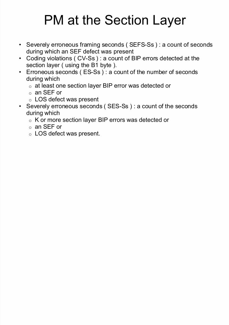
� Severely erroneous framing seconds ( SEFS-Ss ) : a count of secondsduring which an SEF defect was present
� Coding violations ( CV-Ss ) : a count of BIP errors detected at thesection layer ( using the B1 byte ).
� Erroneous seconds ( ES-Ss ) : a count of the number of secondsduring which
o at least one section layer BIP error was detected or o an SEF or o LOS defect was present
� Severely erroneous seconds ( SES-Ss ) : a count of the secondsduring whicho K or more section layer BIP errors was detected or o an SEF or o LOS defect was present.
PM at the Line Layer

8/7/2019 Payload 4(Part2)
http://slidepdf.com/reader/full/payload-4part2 123/133
y
� The line layer performance parameters aredivided into near end ( NE ) and the far end( FE )
� For the near-end line layer, performanceparameters are :o NE line coding violations ( CV-Ls ) : a count of
BIP errors detected at the line layer.o NE line erroneous seconds ( ES-Ls ) : a counter
in seconds during which at least one line layer BIP error was detected or an AIS-L defect waspresent
o NE line severely erroneous seconds ( SES-Ls )
PM at the Line Layer

8/7/2019 Payload 4(Part2)
http://slidepdf.com/reader/full/payload-4part2 124/133
y
� NE line unavailable seconds ( UAS-Ls ) : a count in seconds duringwhich the line was considered unavailable.
� NE line failure counts ( FC-L ) : a count of the number of near-end linefailure events.o A failure event begins when an AIS-L is declared and ends when an AIS-L
is cleared.
� Protection switching count ( PSC ) : relates to systems that areequipped with two switching fabrics, the working and the protectiono For working line : a count of the times that service switched from the
monitored line to the protection line + the times it switched back to theworking line.
o For protection line : a count of the times that service switched from anyworking line to the protection line + the times it switched back to theworking line.
PM at the Line Layer

8/7/2019 Payload 4(Part2)
http://slidepdf.com/reader/full/payload-4part2 125/133
y
� Protection switching duration ( PSD ) : a count insecondso For working line : a count in seconds that indicates the
duration of time service was carried on the protectionline.
o For protection line : a count in seconds that indicatesthe duration of time the protection line was used tocarry service.
� STS pointer justification ( STS-PJ ) : a count of the
STS pointer adjustments created or absorbed byan NE due to differences in the frame rates of incoming and outgoing SONET signals.o The STS-PJ parameter is accumulated for a non-
terminated STS path.
PM at the Line Layer

8/7/2019 Payload 4(Part2)
http://slidepdf.com/reader/full/payload-4part2 126/133
� FE line erroneous seconds ( ES-LFEs ) : a countin seconds during which at least one line BIP error was reported by the FE LTE using the REI-L or anRDI-L defect was present.
� FE line severely erroneous seconds ( SES-LFEs ): a count of the seconds during which K or moreline BIP errors were reported by the FE LTE or anRDI-L defect was present.
� FE line unavailable seconds ( UAS-LFE ) : a countin seconds during which the line was consideredunavailable at the FE.
� FE line failure counts ( FC-LFEs ) : a count of thenumber of FE line failure events.
PM STS Path Layer

8/7/2019 Payload 4(Part2)
http://slidepdf.com/reader/full/payload-4part2 127/133
� STS path layer performance parameters are divided into STS and VT.� Each failure divided into near end and far end� The near end STS path layer performance parameters are :
o NE STS path coding violations ( CV-Ps ) : a count of BIP errorsdetected at the STS path layer.
o NE STS path erroneous seconds ( ES-Ps ) : a count in seconds
during which at least one STS path BIP error was detected or an AIS-P defect was present.
o NE STS path severely erroneous seconds ( SES-Ps ) : a count of the seconds during K or more STS path BIP errors were detected or an AIS-P or LOP-P was present.
o NE STS path unavailable seconds ( UAS-P ) : a count of the
seconds during which the STS path was unavailable.o NE STS path failure counts ( FC-Ps ) : a count of the number of NE
STS path failure events. A failure event begins when an AIS-P or LOP-P is declared and it ends
when it is cleared.
Fig. 5.78 Performancemonitoring: intermediate path

8/7/2019 Payload 4(Part2)
http://slidepdf.com/reader/full/payload-4part2 128/133
monitoring: intermediate path.
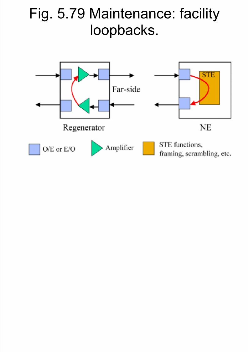
Fig. 5.79 Maintenance: facilityloopbacks
8/7/2019 Payload 4(Part2)
http://slidepdf.com/reader/full/payload-4part2 129/133
loopbacks.
Fig. 5.80 Maintenance: DS-Nloopbacks

8/7/2019 Payload 4(Part2)
http://slidepdf.com/reader/full/payload-4part2 130/133
loopbacks.

8/7/2019 Payload 4(Part2)
http://slidepdf.com/reader/full/payload-4part2 131/133
5.2 SONET and SDH
IP over SONET
IP over SONET
8/7/2019 Payload 4(Part2)
http://slidepdf.com/reader/full/payload-4part2 132/133
� Mapping IP over SONET takes 4 steps1.The IP packet consists of a header and a
variable-length data field, known as a datagram2.There is a protocol known as point-to-point
protocol ( PPP ). The IP datagram isencapsulated ina PPP packet; that is , a header is attached to it.
3.The PPP-encapsulated IP datagram is framed
using high-level data link control ( HDLC ).4.The end result is mapped row-wise and byte-
wise in the SPE. That is, VTs and bytemultiplexing is not applicable in this case.
IP over SONET

8/7/2019 Payload 4(Part2)
http://slidepdf.com/reader/full/payload-4part2 133/133
� PPP provides multiprotocol encapsulation,error control, and link initialization controlfeatures.
� HDLC is primarily used for frame delineation.
That is, to identify the start and the end of theIP/PPP/HDLC frame.
� Each HDLC frame stars and ends with thehexadecimal byte 7E or 0x7E.
� Other 0x7E, if not in the start or the endposition of the frame, it is replaced by the
0 7D f ll d b 0 5E