Embed Size (px)
Citation preview

Payload Criteria (level 1)
Testing and Design of Payload Experiment (level 2)
Design Review at a System Level (level 3)
The payload design fulfills the requirements of the SMD payload. The payload does not eject from the
rocket, but rather takes all reading internal through a clear acrylic housing. The electronics are mounted
on an aluminum rail framework. The camera is kept level throughout the descent phase of the flight by
the ARTCOS, which includes two servo motors. The design includes a custom PCB design, which includes
all components. There are multiple microprocessors which use a serial data bus to transmit data from
one microprocessor to another. A 900 MHz wireless transmitter allows a maximum of 27 mile range of
line of sight wireless transmission.
Drawings and Specifications (level 4)
The payload consists of three main systems: the Atmospherics Data Gathering System (ADGS), the
Autonomous Real-Time Camera Orientation System (ARTCOS), and the Video Capture System (VCS).
Figures a through # are detailed schematics of the payload framework and electronics. The schematics
include exact dimensions. Figure a represents the overall payload with installed components.
Insert picture Here of entire payload
Figure b is a drawing of the ADGS, which consists of a hygrometer, thermometer, pyranometer,
barometric pressure sensor, GPS, lux sensor, UV sensor, wireless transmitter, and micro SD card writer.
Insert Picture Here of ADGS
Figure c represents the Autonomous Real-Time Camera Orientation System (ARTCOS), which consists of
two servo motors, an accelerometer, and a camera.

Insert picture Here of ARTCOS
Picture of ARTCOS mounting.
Picture of perf board mounting.
Picture of battery mounting.
Picture of Solar sensor mounting.
Analysis Results (level 4)
Analysis of the payload’s preliminary design led to several results.
The ADGS was analyzed and it was determined that the battery requirements specified in the
preliminary design were more than sufficient and that the added weight and surface space used by the
number of batteries would be overly excessive; therefore, the number of batteries has decreased to two
nine volt batteries. Second, upon ordering several parts were deemed difficult to obtain and as such
were removed from the design. The secondary pressure sensor and the secondary UV sensor were
removed from the payload design due to this reason. The design then changed to include two of the
chosen primary sensors for redundancy.
The preliminarily chosen video camera for the VCS was deemed difficult to obtain during the ordering
process. The video camera was then changed to a different model, which is easily obtainable but a little
more costly.

The ARTCOS was analyzed and it was determined necessary to include a second microprocessor solely
dedicated to controlling the servos, while the first is solely dedicated to saving the pictures. The was
determined after realizing that when a picture is being saved to the micro SD card, the microprocessor is
not able to perform other tasks, and the delay time to save a picture was determined, after researching
the datasheet, to be around fifteen seconds. With the new configuration the servos are able to adjust
without interference and all accelerometer data is able to be stored.
Table # demonstrates the results of the system analysis.
System Concern Result
ADGS Too Many Batteries Number of Batteries Decrease to Two
ADGS Pressure and UV Secondary Sensors Difficult to Obtain
Use Two Primary Sensors
ACS Camera Difficult to Obtain Different Model Chosen
ARTCOS Not Enough Processing Power Added Microprocessor
Test Results (level 4)
!!!! If we launch the big rocket with the payload in it, the graphs of the sensor readings can go in this
section…………………………..
The result of testing is that the chosen sensors function properly and fulfill their specific purposes.
However, one sensor was removed from the preliminary design as a result of testing. The HH10D has
been removed. It is a relative humidity sensor which outputs a digital frequency calculated through a
clock signal provided by the Arduino Mega. The problem is that the Arduino Mega has only one clock
signal. The clock signal is also used for timing other purposes. In order to use the Arduino’s clock signal
for other purposes, a new clock signal would have to be added to the circuit. The extra clock signal
would add extra hardware and complexity to the circuit. For this reason the HH10D has been removed
from the design.
Integrity of Design (level 4)
System Level Functional Requirements (Level 3)
Table # lists the functional requirements of the payload the design feature that satisfies that
requirement.
SOW # Requirement Satisfying Design Feature
3.1.3.1
UV Radiation SU100
Solar Irradiance TSL2561, SP110
Humidity HIH4030
Temperature BMP180

Pressure BMP180
3.1.3.2
0.2Hz Data During Descent 16MHz Arduino Mega 2560, Software
3.1.3.3
0.016Hz Data After Landing 16MHz Arduino Mega 2560, Software
3.1.3.4
Post-Landing Data Termination Software
3.1.3.5
2 Descent Pictures VC0706, 1080p Video Camera
3 Landing Pictures VC0706, 1080p Video Camera
3.1.3.6
Horizon Orientation ARTCOS
3.1.3.7
Onboard Data Storage Micro SD
Data Transmission 900MHz XBee Radios
3.1.3.8
Apogee Separation No Separation, Clear Acrylic Housing
3.1.3.9
GPS LS20031
3.1.3.10
2500ft Min. Separation No Separation, Clear Acrylic Housing
3.2
Scientific Method Scheduling, Analysis, Testing, Documentation
3.3
UAV Not Applicable, SMD Selection
3.4
Jettisoned Components No Separation, Clear Acrylic Housing
3.5
Recoverable and Reusable Aluminum Framework, No Separation
Approach to Workmanship (level 3)
We take pride in our work. We hand solder all the components. ??????????????????
Test Plan of Components and Functionality (level 3)
Testing began on a breadboard using breakout boards. Each component was tested individually in order
to determine the proper wiring and software. Next the components were integrated together on the
breadboard to determine the correct wiring for the components to operate together. Figure # shows the
breadboard testing.

Voltmeters were used to determine if the components were receiving the correct voltage and
amperage, and also to verify that the microcontrollers contained the correct voltage regulators. Several
times there were issues with components not receiving enough power and the voltmeter was a valuable
tool. Verification of component functionality was measured by three parameters: hardware, software,
and data interpretation. Table # lists the dates in which each parameter was satisfied for each individual
component.
Component Hardware Software Data Interpretation
BMP180 Nov. 16 Nov. 16 Nov. 16
TSL2561 Nov. 16 Nov. 16 Nov. 16
HIH4030 Nov. 16 Nov. 16 Nov. 19
Camera Dec. 5 Dec. 5 Dec. 5
SU100 Dec. 12 Dec. 12 Dec. 12
SP110 Dec. 12 Dec. 12 Dec. 12
LS20031 Nov. 17 Nov. 17 Nov. 17
XBee Dec. 6 Nov. 17 -
ADXL345
The following paragraphs specify each components hardware configuration, software, and data
interpretation. The components are listed in the order of which they were tested.
BMP180 (level 4)
The first sensor tested on the breadboard was the Bosh BMP180 which is mounted on a breadboard
distributed from Sparkfun. The sensor uses the I2C data bus interface and requires a 3.3 Volt input

voltage. The microcontroller used for the testing is the Arduino Mega 2560. Figure # demonstrates the
proper wiring of the sensor determined through testing.
The software used to read the BMP180 and convert the raw reading into usable pressure and
temperature data is written in Arduino C. The data sheet for the BMP180 lists the conversion
algorithms. Figure # is a flow chart from the BMP180 datasheet that represents how to obtain pressure
and temperature readings from the sensor. This flow chart has been determined to be correct through
testing.


TSL2561 (level 4)
The next component tested on the breadboard was the Taos TSL2561 lux sensor. The sensor utilizes the I2C
data bus. The wiring is similar to the BMP180. Figure # shows the correct wiring as determined through
testing.
The software for the TSL2561 was determined through analysis of the datasheet. The datasheet presents
pseudo code for reading the TSL2561 registers. Figure # is the pseudo code from the datasheet.

The raw data from theTSL2561 registers must be converted in order for them to represent actual lux values.
The datasheet presents the conversion factors used to calculate lux from the raw data. Figure # is the
conversion factors from the TSL2561 datasheet. CH1 and CH0 are register values.
The TSL2561 and the BMP180 were then integrated together. Information found at the I2C website
(http://www.i2c-bus.org/) showed that 4.7 killiohm pull-up resistors needed to be added to the Serial Clock
and Serial Data lines of the bus when multiple devices are on the bus. Figure # shows the proper wiring for
the TSL2561 and BMP180 on the same circuit.
HIH4030 (level 4)
The Honeywell HIH4030 is a relative humidity sensor. To begin testing we ordered a breakout board from
Sparkfun which included a PCB with a HIH4030 sensor mounted onto it. The breakout board allowed
through hole testing as opposed to surface mount testing. The HIH4030 requires a five volt power source to
operate, which the Arduino Mega provides through its five volt regulator. The HIH4030 outputs an analog
signal between zero and five volts. This output signal wire is connected to an analog in pin of the Arduino
Mega. Figure # represents the proper wiring of the HIH4030 as determined through testing.

The software for the HIH4030 takes the analog input value and uses a conversion factor to convert from the
raw reading to the actual relative humidity value. This conversion factor is found in the datasheet. The
conversion factor also utilizes the temperature reading from the BMP180 to acquire an even more accurate
relative humidity reading. After analyzing the datasheet, the following function, written in Arduino C, was
formulated to calculate the relative humidity from the HIH4030.
Integrating the HIH4030 with the BMP180 and TSL2561 requires no extra hardware. The devices do not
utilize the same data busses. Figure # shows the proper wiring after integrating the HIH4030 with the other
two sensors.

HH10D (level 4)
The HH10D is a relative humidity sensor which outputs a digital frequency signal. There are also two
calibration values stored in the EEPROM which must be read from the I2C data bus. The digital frequency
signal is simply read by the Arduino Mega through a digital I/O pin. Figure # is a schematic showing the
proper wiring of the HH10D alone on a circuit.
In order to get a relative humidity reading from the HH10D, the two calibration values must be read from
the EEPROM at the start of the program. Then, the frequency signal must be polled. The frequency value
along with the calibration values are used in a formula specified in the datasheet. Figure # is a table
specifying the calculation algorithm and EEPROM values.

Integrating the HH10D into the circuit with the HIH4030, BMP180, and TSL2561 simply involves connecting
the I2C lines and the digital frequency line to the Arduino Mega. To simplify the connections even further,
since the calibration values do not change the I2C connections can be disconnected after reading the
calibration values the first time. Figure # is a schematic showing the wiring of the four sensors.
As mentioned previously in the Test Results section, the HH10D has been removed from the design.
SU100 (level 4)
The SU100 is a ultraviolet radiation sensor distributed by apogee instruments. The sensor outputs a voltage
which represents the level of ultraviolet radiation. This output voltage is read into the Arduino Mega
through an analog pin. There are multiple ways in which to wire the SU100. The sensor has negative,
positive, and ground output signals. One way to use the SU100 is subtract the negative voltage from the
positive voltage use the difference in an algorithm; this is known as a differential measurement. The second
way to use the SU100 is to connect the negative to the ground and read the output from the positive signal;
this is known as a single-ended measurement. Testing was performed with a voltmeter as shown in Figure #.

Through testing, the single-ended measurement gives a more accurate reading. Therefore, this is the wiring
used in the design. Figure # shows the wiring of the SU100.
When forming the software, the first issue is the reference voltage of the analog pins of the Arduino Mega.
The default reference voltage is five volts, and the analog to digital converter on the Arduino Mega is ten
bits. This means that the five volts is split into 1024 sections. Therefore, with a reference voltage of five
volts, the software can only detect differences of about four millivolts. The problem with this is that the
SU100 outputs a voltage between zero and 27 millivolts. A difference of four millivolts will represent a large
change in ultraviolet radiation. In order to make the readings more accurate, the reference voltage of the

Arduino Mega has been changed to 1.1 volts. The software can detect changes of about one millivolt. The
datasheet provides an algorithm for calculating the ultraviolet radiation from the voltage reading. This
algorithm is used in the software. The following code is the code used in the software for the SU100. The
function returns a value accurate to two decimal places.
SP110 (level 4)
The functionality of the SP110 is extremely similar to the SU100. The difference is that the SP110 reads solar
irradiance and outputs a higher voltage. In all other regards the functionality of the two sensors are the
same.
LS20031 (level 4)
The LS20031 is a GPS module manufactured by Locosys. The GPS uses a serial UART data bus for data
transfer to the Arduino Mega. The GPS receives from a satellite a NMEA statement. It receives several NMEA
statements. The software decides which NMEA statement to parse. Our software takes readings of latitude,
longitude, and altitude from the GGS NMEA statement. The GPS has a transmit and a receive pin. The
transmit pin is connected to the UART receive pin of the Arduino Mega and the receive pin is connected to
UART transmit pin of the Arduino Mega. Figure # shows the proper wiring of the LS20031.

The NMEA statement from the GPS is sent of the transmit line character by character. The software looks at
the statement and decides if it is the correct NMEA statement. Then the software parses the latitude,
longitude, and altitude from the statement. The GPS code can be found in Appendix #.
Micro SD (level 4)
The payload will save all sensor data to a sixteen gigabyte high capacity micro secure digital (SD) card. The
micro SD card will organize data into a thirty two bit file allocation table (FAT32) file system. A micro SD card
allows for quick retrieval of data. The micro SD card utilizes the SPI bus of the Arduino Mega for data
transfer. Digital pins 50 through 53 are the SPI pins of the Arduino Mega. From the advice of technicians at
Parallax there is a one Killiohm resistor on each of the SPI data lines. The correct wiring of the micro SD card
is shown in Figure #.
Arduino has a pre-made library for micro SD cards. This library is what the software uses to store data to the
micro SD card.
XBee (level 4)

The XBee-PRO XSC S3B is capable of transmitting telemetry to a line of sight range of twenty-eight miles
when coupled with a high gain antenna. The transmitter operates at the 900 Megahertz frequency band.
The 900 Megahertz band is organized into twelve different channels to help prevent interference from other
devices transmitting at this frequency. The XBee-PRO XSC S3B requires a low voltage of only 2.4 volts to 3.6
volts. Therefore, the XBee is connected to the 3.3 volt regulator of the Arduino Mega. The data from the
sensors is sent to the Arduino Mega and then transmitted to the XBee through one of the UART serial data
busses. The transmit line of the Arduino Mega is connected to the receive line of the XBee. Figure # shows
the wiring of the XBee.
The XBee is located away from all deployment altimeters, in a completely separate compartment.
The data is transmitted from the payload XBee to a corresponding XBee connected to a high gain yagi
antenna at the ground station. The ground station XBee is uses a Sparkfun adapter with a USB connection to
communicate with the ground station computer. When testing the adapter it was realized that there was a
problem with the communication link. Through the advice of Digi Technical Support, the adapter had to be
modified. The following advice was found on Sparkfun’s forums
(https://forum.sparkfun.com/viewtopic.php?f=13&t=33274):

The LED was desoldered from the XBee adapter as shown in Figure #.
Range testing has been performed in order to verify the functionality of the wireless transmission. To
specify how range testing was performed, we used GPS to determine the starting location and final location
where the XBees lost connection. Range testing shows that the XBee can transmit at least two miles even
without line of sight. Figure # shows the starting and stopping GPS coordinates along with the distance
between them.

The wiring schematic of the overall ADGS is shown in Figure # and the code for the software is found in
Appendix #.

Batteries (level 4)
The ADGS is powered by a nine volt battery. The ARTCOS is powered by two nine volt batteries. The VCS is
powered by a 3.7 volt battery.
Voltage Regulators (level 4)
The current design uses the voltage regulators onboard the Arduino. However, after consulting experts at
Adafruit the design will include buck converters. According to experts at Adafruit, voltage regulators are
inherently inefficient and buck converters are extremely efficient. The buck converters in the design are
distributed by Adafruit. They are manufactured by Traco Power product number TSR 1-2450.
ARTCOS (level 4)
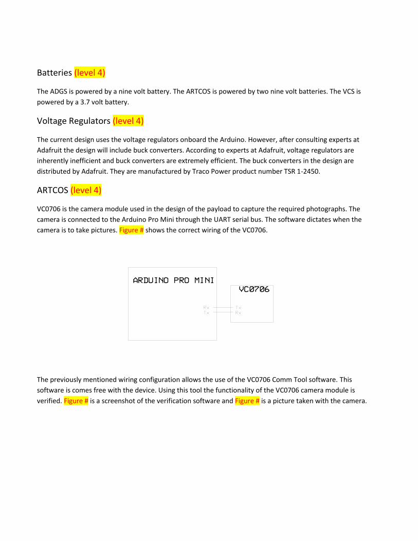
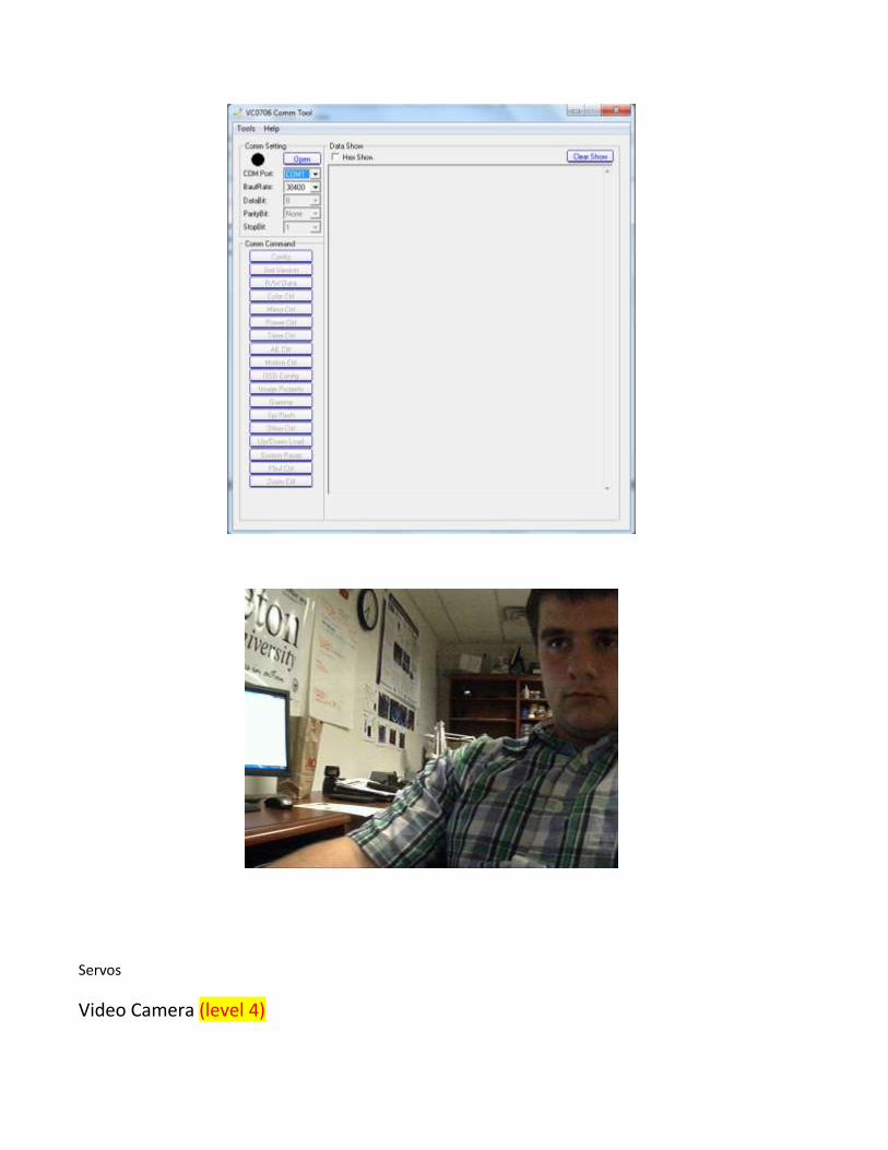
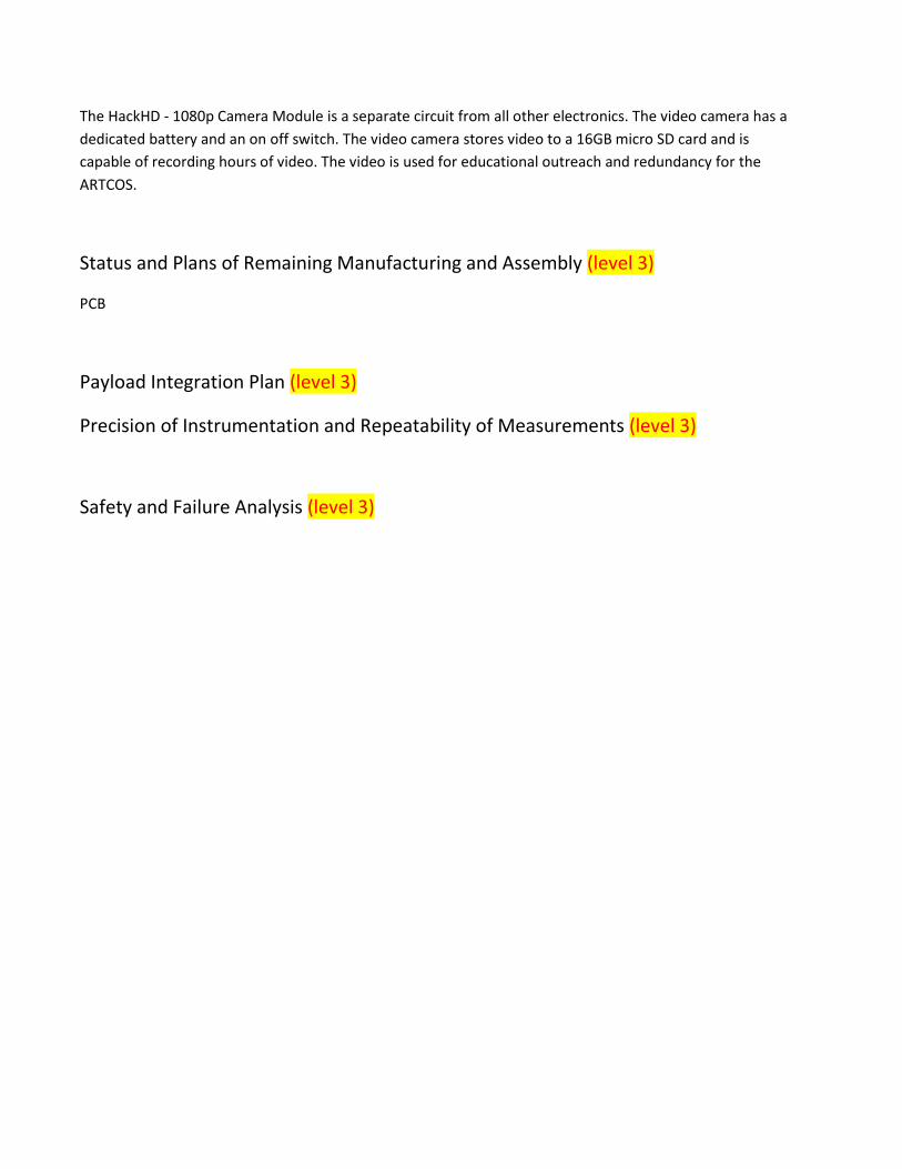
VC0706 is the camera module used in the design of the payload to capture the required photographs. The
camera is connected to the Arduino Pro Mini through the UART serial bus. The software dictates when the
camera is to take pictures. Figure # shows the correct wiring of the VC0706.
The previously mentioned wiring configuration allows the use of the VC0706 Comm Tool software. This
software is comes free with the device. Using this tool the functionality of the VC0706 camera module is
verified. Figure # is a screenshot of the verification software and Figure # is a picture taken with the camera.
Servos
Video Camera (level 4)
The HackHD - 1080p Camera Module is a separate circuit from all other electronics. The video camera has a
dedicated battery and an on off switch. The video camera stores video to a 16GB micro SD card and is
capable of recording hours of video. The video is used for educational outreach and redundancy for the
ARTCOS.
Status and Plans of Remaining Manufacturing and Assembly (level 3)
PCB
Payload Integration Plan (level 3)
Precision of Instrumentation and Repeatability of Measurements (level 3)
Safety and Failure Analysis (level 3)

Appendix # - ADGS Arduino Software
Code_12_21_2012.ino
/***************************************************************************************/
/* Tarleton Aeronautical Team
/* University Student Launch Initiative 2012-2013
/* Atmospheric Data Gathering Circuit
/*
/* Created: November 16, 2012
/*
/* CHANGE LOG -
/*
/* November 16, 2012:
/* Editor's name:
/* JP
/* Changes:
/* Set up change log and main structure of the code.
/* Added the BMP180, TSL2561, and HH10D functionality which all use I2C.
/* Simply printed readings to the Serial port.
/*
/* November 17, 2012:
/* Editor's name:
/* JP
/* Changes:
/* Changed baud rate to 19200 to match the XBee.
/* Added the microSD and GPS functionality.
/*
/* November 19, 2012:
/* Editor's name:
/* JP
/* Changes:
/* Added the HIH4030 functionality.
/*
/* December 6, 2012:
/* JP
/* Changes:
/* Took out HH10D.
/* Added timestamp in milliseconds.
/*
/* December 11, 2012:
/* Took out a lot of the SD writes.
/*
/* December 12, 2012:
/* Added SU100 and SP110
/* Changed the HIH functioning because the reference
/* voltage for the Solar sensors is 1.1 and it
/* is 5V. The ProMini sends readings to the Mega
/* over Serial2
/*
/* December 14, 2012:
/* Added code to read the ADXL from the Mini.
/***************************************************************************************/

// Preprocessing Directives
#include <FreqCounter.h>
#include <Wire.h> // I2C Library
#include <Arduino.h> // This is used for Arduino-1.0 for many functions.
#include "TSL2561.h"
#include <SD.h>
#define SERIAL_BAUD_RATE 19200
#define GPS_BAUD_RATE 57600
#define XBEE_BAUD_RATE 19200
// Global Variables
// HIH4030
int HIH4030_RH;
int HIH4030_PIN = 0;
// TSL2561
int TSL2561_LUX;
// BMP180
short BMP180_TEMP;
long BMP180_PRESSURE;
long BMP180_INIPRESSURE;
long BMP180_ALTITUDE;
// GPS
char GPSBUFFER[100];
// Solar
long frontSU; // pin 12
long backSU; // pin 13
long frontSP; // pin 8
long backSP; // Pin 9
// ADXL
String ADXLBUFFER;
// XBee
String TELEMETRY_STRING = "";
// SD
File DATAFILE;
// Time
long TIMER;
// Setup
void setup(){
// XBee Serial connections.
Serial3.begin(SERIAL_BAUD_RATE);
Serial2.begin(19200);
// GPS Serial Connections.

Serial1.begin(GPS_BAUD_RATE);
// Arduino Mini HIH4030 Connection
//Serial2.begin(19200);
Wire.begin();
// Initiates the SD card using cs pin 53
SD.begin(53);
// Create the SD file and write a title //
DATAFILE = SD.open("datalog.txt", FILE_WRITE); //
DATAFILE.println();
DATAFILE.println();
DATAFILE.println("System Initializing...");
DATAFILE.print("Serial Baud Rate: "); DATAFILE.println(SERIAL_BAUD_RATE);
DATAFILE.print("GPS Baud Rate: "); DATAFILE.println(GPS_BAUD_RATE);
DATAFILE.print("XBee Baud Rate: "); DATAFILE.println(XBEE_BAUD_RATE);
DATAFILE.close();
//Calibration variables needed for the BMP180 to give accurate data.
TSL2561_calibration();
//Calibration variables needed for the BMP180 to give accurate data.
BMP180_calibration();
BMP180_TEMP = BMP180_getTemperatureIni();
BMP180_INIPRESSURE = BMP180_getPressureIni();
// Setting the refernece voltage because the Solar sensors output
// such a low voltage, and the ADC is only 10 bit.
analogReference(INTERNAL1V1);
}
// Loop
void loop(){
// Read lux value from the TSL2561.
TSL2561_LUX = TSL2561_getLux();
BMP180_TEMP = BMP180_getTemperature(BMP180_readUT());
// temperature must be populated prior to pressure
BMP180_PRESSURE = BMP180_getPressure(BMP180_readUP());
// pressure must be calculated before altitude
BMP180_ALTITUDE = BMP180_getAltitude(BMP180_PRESSURE, BMP180_INIPRESSURE);
// Function parameters are pin # and temperature.
HIH4030_RH = HIH4030_readRH(float(BMP180_TEMP)/10);
// Gathers GPS data and stores them to GPSBUFFER
GPS();
// Solar readings
frontSU = Solar(12);
backSU = Solar(13);
frontSP = Solar(8);
backSP = Solar(9);
// Accelerometer
//ADXL();
// Save the current time since program started.
TIMER = millis();
// Construct the string that is transmited via the XBee.
TELEMETRY_STRING = " ";
TELEMETRY_STRING += HIH4030_RH;
TELEMETRY_STRING += " ";
TELEMETRY_STRING += TSL2561_LUX;
TELEMETRY_STRING += " ";
TELEMETRY_STRING += BMP180_TEMP;
TELEMETRY_STRING += " ";
TELEMETRY_STRING += BMP180_PRESSURE;
TELEMETRY_STRING += " ";
TELEMETRY_STRING += BMP180_ALTITUDE;
TELEMETRY_STRING += " ";
TELEMETRY_STRING += String(GPSBUFFER);
TELEMETRY_STRING += " ";
TELEMETRY_STRING += frontSU;
TELEMETRY_STRING += " ";
TELEMETRY_STRING += backSU;
TELEMETRY_STRING += " ";
TELEMETRY_STRING += frontSP;
TELEMETRY_STRING += " ";
TELEMETRY_STRING += backSP;
TELEMETRY_STRING += " ";
//TELEMETRY_STRING += ADXLBUFFER;
//TELEMETRY_STRING += " ";
// Transmit
Serial3.println(TELEMETRY_STRING);
delay(100);
TELEMETRY_STRING += TIMER;
TELEMETRY_STRING += " ";
DATAFILE = SD.open("datalog.txt", FILE_WRITE);
DATAFILE.println(TELEMETRY_STRING);
DATAFILE.close();
delay(100);
}
void ADXL(){
ADXLBUFFER = "";
int xAcc;
int yAcc;
int zAcc;

Serial2.print("A");
while(!Serial2.available());
xAcc = Serial2.parseInt();
Serial2.read();
yAcc = Serial2.parseInt();
Serial2.read();
zAcc = Serial2.parseInt();
Serial2.read();
ADXLBUFFER += xAcc;
ADXLBUFFER += " ";
ADXLBUFFER += yAcc;
ADXLBUFFER += " ";
ADXLBUFFER += zAcc;
ADXLBUFFER += "";
}

BMP180.ino /* This Header File contains functions needed to operate the BMP180.
Discriptions of each funtion are included above the fucntions themselves.
NOTE: If you change the OSS value, you must also change the delay value
in the bmp180ReadUT() funtion.
*/
#define BMP180_ADDRESS 0x77 // I2C address of BMP085 is 0x77
/* NOTE: OSS: can be set between 0-3, which requires
changes to the delay in the bmpReadUT();
{0 = 4.5ms, 1 = 7.5ms, 2 = 13.5ms, 3 = 25.5ms}
*/
const unsigned char OSS = 3; // Oversampling Setting
int ac1;
int ac2;
int ac3;
unsigned int ac4;
unsigned int ac5;
unsigned int ac6;
int b1;
int b2;
int mb;
int mc;
int md;
long b5;
// Stores all of the bmp085's calibration values into global variables
// Calibration values are required to calculate temp and pressure
// This function should be called at the beginning of the program
// Calculate temperature given ut.
// Value returned will be in units of 0.1 deg C
///////////////////////////////////////////////////////////////////////
short BMP180_getTemperature(unsigned int ut)
{
long x1, x2;
x1 = (((long)ut - (long)ac6)*(long)ac5) >> 15;
x2 = ((long)mc << 11)/(x1 + md);
b5 = x1 + x2;
return ((b5 + 8)>>4);
}
///////////////////////////////////////////////////////////////////////
// Calculate pressure given up
// calibration values must be known
// b5 is also required so bmp085GetTemperature(...) must be called first.
// Value returned will be pressure in units of Pa.
////////////////////////////////////////////////////////////////////////
long BMP180_getPressure(unsigned long up)
{

long x1, x2, x3, b3, b6, p;
unsigned long b4, b7;
b6 = b5 - 4000;
// Calculate B3
x1 = (b2 * (b6 * b6)>>12)>>11;
x2 = (ac2 * b6)>>11;
x3 = x1 + x2;
b3 = (((((long)ac1)*4 + x3)<<OSS) + 2)>>2;
// Calculate B4
x1 = (ac3 * b6)>>13;
x2 = (b1 * ((b6 * b6)>>12))>>16;
x3 = ((x1 + x2) + 2)>>2;
b4 = (ac4 * (unsigned long)(x3 + 32768))>>15;
b7 = ((unsigned long)(up - b3) * (50000>>OSS));
if (b7 < 0x80000000)
p = (b7<<1)/b4;
else
p = (b7/b4)<<1;
x1 = (p>>8) * (p>>8);
x1 = (x1 * 3038)>>16;
x2 = (-7357 * p)>>16;
p += (x1 + x2 + 3791)>>4;
return p;
}
/////////////////////////////////////////////////////////////////////
//Getting altitude
// NOTE: * 100 to get altitude
///////////////////////////////////////////////////
long BMP180_getAltitude(float pressure, float ini_pressure)
{
long altitude;
float x1,x2,x3;
x1= (pressure/ini_pressure);
x2= (1/5.255);
x3= pow(x1,x2);
altitude = 443300*(1-x3);
return altitude;
}
///////////////////////////////////////////////////
// Read 1 byte from the BMP085 at 'address'
/////////////////////////////////////////////////
char BMP180_read(unsigned char address)
{
unsigned char data;
Wire.beginTransmission(BMP180_ADDRESS);

Wire.write(address);
Wire.endTransmission();
Wire.requestFrom(BMP180_ADDRESS, 1);
while(!Wire.available());
return Wire.read();
}
/////////////////////////////////////////////////
// Read 2 bytes from the BMP085
// First byte will be from 'address'
// Second byte will be from 'address'+1
/////////////////////////////////////////////////
int BMP180_readInt(unsigned char address)
{
unsigned char msb, lsb;
Wire.beginTransmission(BMP180_ADDRESS);
Wire.write(address);
Wire.endTransmission();
Wire.requestFrom(BMP180_ADDRESS, 2);
while(Wire.available()<2)
;
msb = Wire.read();
lsb = Wire.read();
return (int) msb<<8 | lsb;
}
//////////////////////////////////////////////////
// Read the uncompensated temperature value
// NOTE: the delay here may change depending on the Over Sampling selected.
//////////////////////////////////////////////////
unsigned int BMP180_readUT()
{
unsigned int ut;
// Write 0x2E into Register 0xF4
// This requests a temperature reading
Wire.beginTransmission(BMP180_ADDRESS);
Wire.write(0xF4);
Wire.write(0x2E);
Wire.endTransmission();
// Wait at least 4.5ms
delay(26);
// Read two bytes from registers 0xF6 and 0xF7
ut = BMP180_readInt(0xF6);

return ut;
}
/////////////////////////////////////////////////////
// Read the uncompensated pressure value
/////////////////////////////////////////////////////////
unsigned long BMP180_readUP()
{
unsigned char msb, lsb, xlsb;
unsigned long up = 0;
// Write 0x34+(OSS<<6) into register 0xF4
// Request a pressure reading w/ oversampling setting
Wire.beginTransmission(BMP180_ADDRESS);
Wire.write(0xF4);
Wire.write(0x34 + (OSS<<6));
Wire.endTransmission();
// Wait for conversion, delay time dependent on OSS
delay(2 + (3<<OSS));
// Read register 0xF6 (MSB), 0xF7 (LSB), and 0xF8 (XLSB)
Wire.beginTransmission(BMP180_ADDRESS);
Wire.write(0xF6);
Wire.endTransmission();
Wire.requestFrom(BMP180_ADDRESS, 3);
// Wait for data to become available
while(Wire.available() < 3)
;
msb = Wire.read();
lsb = Wire.read();
xlsb = Wire.read();
up = (((unsigned long) msb << 16) | ((unsigned long) lsb << 8) | (unsigned long) xlsb)
>> (8-OSS);
return up;
}
// Stores all of the bmp085's calibration values into global variables
// Calibration values are required to calculate temp and pressure
// This function should be called at the beginning of the program
void BMP180_calibration()
{
ac1 = BMP180_readInt(0xAA);
ac2 = BMP180_readInt(0xAC);
ac3 = BMP180_readInt(0xAE);
ac4 = BMP180_readInt(0xB0);
ac5 = BMP180_readInt(0xB2);
ac6 = BMP180_readInt(0xB4);
b1 = BMP180_readInt(0xB6);
b2 = BMP180_readInt(0xB8);

mb = BMP180_readInt(0xBA);
mc = BMP180_readInt(0xBC);
md = BMP180_readInt(0xBE);
}
/////////////////////////////////////////////////////////////////////
//Setting baseline altitude.
//////////////////////////////////////////////////
long BMP180_getPressureIni(){
long x1 = 0;
double ini_pressure;
long total = 0;
for(int i=1; i <=20; i++){
x1 = BMP180_getPressure(BMP180_readUP());
total += x1;
}
ini_pressure = double(total) / 20;
return long(ini_pressure);
}
//Setting baseline temperature.
//////////////////////////////////////////////////
long BMP180_getTemperatureIni(){
long x1 = 0;
double ini_temperature;
long total = 0;
for(int i=1; i <=20; i++){
x1 = BMP180_getTemperature(BMP180_readUT());
total += x1;
}
ini_temperature = double(total) / 20;
return long(ini_temperature);
}

GPS.ino /*
GPS
References:
http://www.sparkfun.com/tutorials/176
*/
int numSats = 0; // number of satallites tracking
int fixType = 0;
int time[] = {0, 0, 0}; // The current time
double latitude = 0.0;
double longitude = 0.0;
long gpsaltitude = 0;
long adjustedGpsAltitude;
long maxAlt = 0;
int speed = 0;
int txCount = 0;
int ExOnce = 0;
int FalcomCheck = 0;
unsigned long GpsOffTime = 0;
// All the Functions used for the GPS, reading the NMEA statement, formatting the data
void GPS(){
Serial1.flush();
// Get a GGA string from the GPS, and
// check if it's a valid fix, and extract the data.
getNMEA("$GPGGA");
//delay(100);
numSats = getSats();
fixType = getFixType();
// Make sure we have a valid fix
if (fixType != 0) {
getTime(time);
latitude = getLat();
longitude = getLong();
gpsaltitude = getAlt();
}
// Convert latitude and longitude into strings.
char latString[12];
char longString[12];
doubleToString(latitude, 4, latString);
doubleToString(longitude, 4, longString);
//gpsaltitude=(gpsaltitude - Stepsealevel);
sprintf(GPSBUFFER, "%02d%02d%02d %s %s %ld %d",
time[0], time[1], time[2], latString, longString , gpsaltitude ,numSats);
//Serial.println(GPSBUFFER);
if (fixType > 0) {
if (ExOnce==0){
//digitalWrite(13, HIGH);

}
}
}
// Reads a line from the GPS NMEA serial output
// Give up after trying to read 1000 bytes (~2 seconds)
int readLine(void) {
char c;
byte bufferIndex = 0;
boolean startLine = 0;
byte retries = 0;
while (retries < 20) {
c = Serial1.read();
if (c == -1) {
//delay(2);
continue;
}
if (c == '\n') continue;
if (c == '$') startLine = 1;
if ((bufferIndex == 99) || (c == '\r')) {
if (startLine) {
GPSBUFFER[bufferIndex] = 0;
return 1;
}
}
if (startLine)
GPSBUFFER[bufferIndex++] = c;
//}
else {
retries++;
//delay(50);
}
}
return 0;
}
// Returns a specific field from the buffer
void getField(int getId, char *field, int maxLen) {
byte bufferIndex = 0;
byte fieldId = 0;
byte i = 0;
while (bufferIndex < sizeof(GPSBUFFER)) {
if (fieldId == getId) {
// End of string, or string overflow
if (GPSBUFFER[bufferIndex] == ',' || i > (maxLen - 2)) {
field[i] = 0; // Null terminate
return;
}
// Buffer chars to field
field[i++] = GPSBUFFER[bufferIndex++];
}
else {
// Advance field on comma
if (GPSBUFFER[bufferIndex] == ',') {
bufferIndex++; //Advance in buffer
fieldId++; // Increase field position counter
}
else {
bufferIndex++; // Advance in buffer
}
}
}
// Null terminate incase we didn't already..
field[i] = 0;
}
// Polls for an NMEA sentence of type requested
// Validates checksum, silently retries on failed checksums
int getNMEA(char *getType) {
char type[7];
byte retries = 0;
while (retries < 2) {
if (readLine()) {
;
getField(0, type, sizeof(type));
if (strcmp(type, getType) == 0) {
return 1;
}
}
else {
retries++;
}
}
return 0;
}
// Return the fix type from a GGA string
int getFixType(void) {
char field[5];
getField(6, field, sizeof(field));
int fixType = atoi(field);
return fixType;
}
// Return the altitude in meters from a GGA string
long getAlt(void) {
char field[10];

getField(9, field, sizeof(field));
long altitude = atol(field);
return altitude;
}
// Returns the number of satellites being tracked from a GGA string
int getSats(void) {
char field[3];
getField(7, field, sizeof(field));
int numSats = atoi(field);
return numSats;
}
// Read the latitude in decimal format from a GGA string
float getLat(void) {
char field[12];
getField(2, field, sizeof(field)); // read the latitude
float latitude = atof(field); // convert to a double (precise)
int deg = (int) latitude / 100; // extract the number of degrees
float min = latitude - (100 * deg); // work out the number of minutes
latitude = deg + (float) min/60.0; // convert to decimal format
getField(3, field, sizeof(field)); // get the hemisphere (N/S)
// sign the decimal latitude correctly
if (strcmp(field, "S") == 0)
latitude *= -1;
return latitude;
}
// Read the longitude in decimal format from a GGA string
float getLong(void) {
char field[12];
getField(4, field, sizeof(field)); // read the longitude
float longitude = atof(field); // convert to a double
int deg = (int) longitude / 100; // extract the number of degrees
float min = longitude - (100 * deg); // work out the number of minutes
longitude = deg + (float) min/60.00; // convert to decimal format
getField(5, field, sizeof(field)); // get the E/W status
// sign decimal latitude correctly
if (strcmp(field, "W") == 0)
longitude *= -1;
return longitude;
}
// Converts UTC time to the correct timezone
void convertTime(int *time) {
// How many hours off GMT are we?
float offset = -5;
long sectime = ((long)(time[0]) * 3600) + (time[1] * 60) + time[2];
sectime += (offset * 3600.0);
// Did we wrap around?
if (sectime < 0) sectime += 86400;

if (sectime > 86400) sectime -= 86400;
// Convert back to time
time[0] = (int)(sectime / 3600);
time[1] = (int)((sectime % 3600) / 60);
time[2] = (int)((sectime % 3600) % 60);
}
// Parses a time field from a GGA string
void parseTime(char *field, int *time) {
char tmp[3];
tmp[2] = 0; // Init tmp and null terminate
tmp[0] = field[0];
tmp[1] = field[1];
time[0] = atoi(tmp); // Hours
tmp[0] = field[2];
tmp[1] = field[3];
time[1] = atoi(tmp); // Minutes
tmp[0] = field[4];
tmp[1] = field[5];
time[2] = atoi(tmp); // Seconds
}
// Gets the hours, minutes and seconds from a GGA string
void getTime(int *time) {
char field[12];
getField(1, field, sizeof(field));
parseTime(field, time);
convertTime(time);
}
/* ------------------------- Utility Functions -----------------------------*/
// Returns a string with a textual representation of a float
void doubleToString(double val, int precision, char *string){
// Print the int part
sprintf(string, "%d", (int)(val));
if(precision > 0) {
// Print the decimal point
strcat(string, ".");
unsigned long frac;
unsigned long mult = 1;
int padding = precision -1;
while (precision--) {
mult *=10;
}
if (val >= 0)
frac = (val - (int)(val)) * mult;
else
frac = ((int)(val)- val ) * mult;
unsigned long frac1 = frac;
while (frac1 /= 10) {
padding--;
}
while (padding--) {
strcat(string, "0");

}
// Convert and print the fraction part
sprintf(string+strlen(string), "%d", (int)(frac));
}
}
// Converts a HEX string to an int
int atoh(char c) {
if (c >= 'A' && c <= 'F')
return c - 55;
else if (c >= 'a' && c <= 'f')
return c - 87;
else
return c - 48;
}

HIH4030.ino /* HIH4030 Humidity Sensor
Connect to 5V.
References:
https://www.sparkfun.com/products/9569
http://www.arduino.cc/forum/index.php/topic,19961.0.html
*/
int HIH4030_readRH(float temp){
int raw = getValue();
float RH, TrueRH;
float volts = (float(raw) * 5)/1023;
RH = ((volts/4.8)-0.16)/0.0062;
TrueRH = RH/(1.0546-0.00216*temp);
return int(RH*100);
}
int getValue(){
int value;
long startTime = millis();
long endTime;
Serial2.print('H');
while(!Serial2.available() && (endTime - startTime) < 500){
endTime = millis();
}
value = Serial2.parseInt();
Serial2.read();
return value;
}

Solar.ino long Solar(int pin){
int rawSU;
float milliVolts;
float UV;
rawSU = analogRead(pin);
milliVolts = ((float(rawSU) * 1100)/1023);
UV = milliVolts * 5;
return (long(UV * 100));
}

TSL2561.ino /*
TSL2561 sensor
References:
http://learn.adafruit.com/tsl2561/overview
connect VDD to 3.3V DC
connect GROUND to common ground
ADDR can be connected to ground, or vdd or left floating to change the i2c address
The address will be different depending on whether you let
the ADDR pin float (addr 0x39), or tie it to ground or vcc. In those cases
use TSL2561_ADDR_LOW (0x29) or TSL2561_ADDR_HIGH (0x49) respectively
*/
TSL2561 tsl(TSL2561_ADDR_FLOAT);
void TSL2561_calibration() {
tsl.begin();
// You can change the gain on the fly, to adapt to brighter/dimmer light situations
//tsl.setGain(TSL2561_GAIN_0X); // set no gain (for bright situtations)
tsl.setGain(TSL2561_GAIN_16X); // set 16x gain (for dim situations)
// Changing the integration time gives you a longer time over which to sense light
// longer timelines are slower, but are good in very low light situtations!
tsl.setTiming(TSL2561_INTEGRATIONTIME_13MS); // shortest integration time (bright
light)
//tsl.setTiming(TSL2561_INTEGRATIONTIME_101MS); // medium integration time (medium
light)
//tsl.setTiming(TSL2561_INTEGRATIONTIME_402MS); // longest integration time (dim light)
// Now we're ready to get readings!
}
/*
* The problem is that I don't know what units the raw readings are in.
* Once they are converted to lux it is simple to convert to
* W/m^2 for a single wavelength but not for a large range.
*/
int TSL2561_getLux(){
// More advanced data read example. Read 32 bits with top 16 bits IR, bottom 16 bits
full spectrum
// That way you can do whatever math and comparions you want!
int lux;
uint32_t lum = tsl.getFullLuminosity();
uint16_t ir, full;
ir = lum >> 16;
full = lum & 0xFFFF;
lux = tsl.calculateLux(full, ir);

return lux;
}