Embed Size (px)
Citation preview
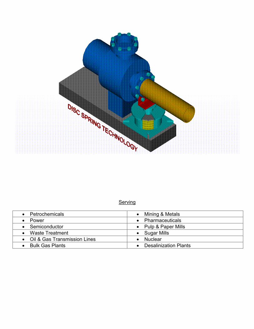
Serving
• Petrochemicals • Mining & Metals • Power • Pharmaceuticals • Semiconductor • Pulp & Paper Mills • Waste Treatment • Sugar Mills • Oil & Gas Transmission Lines • Nuclear • Bulk Gas Plants • Desalinization Plants

NOTES:
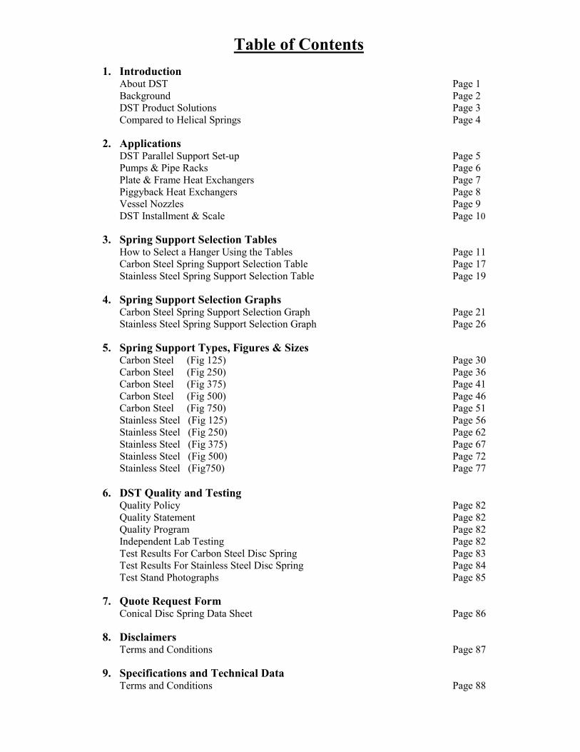
Table of Contents
1. Introduction About DST Page 1 Background Page 2 DST Product Solutions Page 3 Compared to Helical Springs Page 4
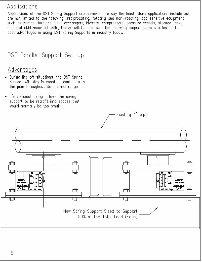
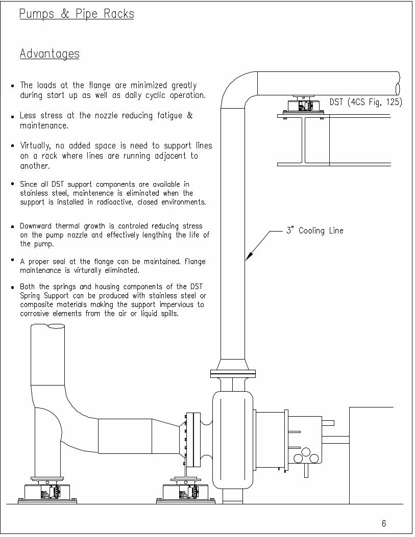
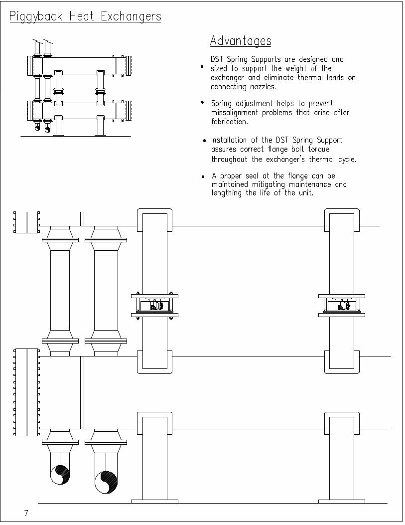
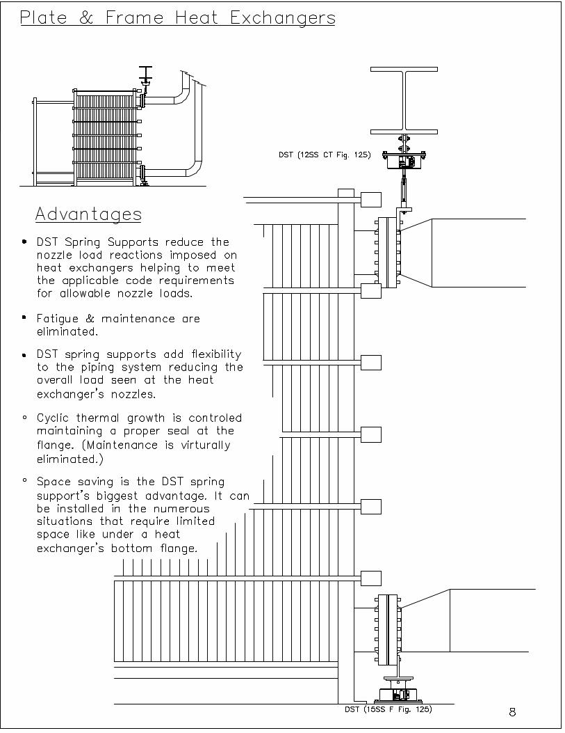
2. Applications DST Parallel Support Set-up Page 5 Pumps & Pipe Racks Page 6 Plate & Frame Heat Exchangers Page 7 Piggyback Heat Exchangers Page 8 Vessel Nozzles Page 9 DST Installment & Scale Page 10
3. Spring Support Selection Tables
How to Select a Hanger Using the Tables Page 11 Carbon Steel Spring Support Selection Table Page 17 Stainless Steel Spring Support Selection Table Page 19
4. Spring Support Selection Graphs
Carbon Steel Spring Support Selection Graph Page 21 Stainless Steel Spring Support Selection Graph Page 26
5. Spring Support Types, Figures & Sizes
Carbon Steel (Fig 125) Page 30 Carbon Steel (Fig 250) Page 36 Carbon Steel (Fig 375) Page 41 Carbon Steel (Fig 500) Page 46 Carbon Steel (Fig 750) Page 51 Stainless Steel (Fig 125) Page 56 Stainless Steel (Fig 250) Page 62 Stainless Steel (Fig 375) Page 67 Stainless Steel (Fig 500) Page 72 Stainless Steel (Fig750) Page 77
6. DST Quality and Testing
Quality Policy Page 82 Quality Statement Page 82 Quality Program Page 82 Independent Lab Testing Page 82 Test Results For Carbon Steel Disc Spring Page 83 Test Results For Stainless Steel Disc Spring Page 84 Test Stand Photographs Page 85
7. Quote Request Form
Conical Disc Spring Data Sheet Page 86
8. Disclaimers Terms and Conditions Page 87
9. Specifications and Technical Data
Terms and Conditions Page 88
Patent Pending, All Rights Reserved. 1
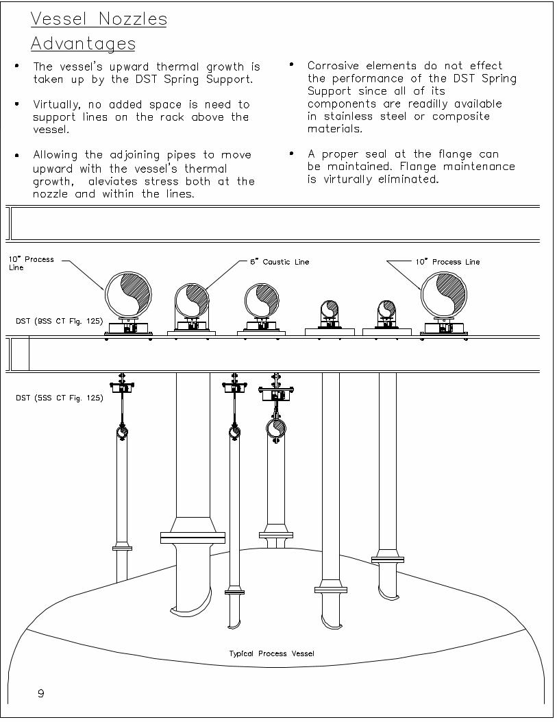
WHY USE DST SPRING SUPPORTS?
ABOUT DST DST has developed an innovative spring support system satisfying small movements in limited space. These features are not offered by conventional helical coil spring supports. Through careful manipulation of the conical spring washer’s dimensional and mechanical characteristics, DST has developed a series of spring supports, which matches and exceeds the performance of helical coil spring supports in instances that require limited space. DST supports are based on the use of custom engineered conical (Belleville) springs, which allows DST to offer a full range of patented spring supports that suite the need for large loads and small movements. This catalog provides conical spring support sizes that will support loads from 50 to 50,000 lbs and movements from 0 to 3/4". The working range for DST springs is between 45% to 85% maximum compression. However, for safety and durability, DST springs are designed for 100% compression without being overstressed. All the items shown in this catalog are ‘Range Machines’. They are made to be applied to a range of loads and movements. Custom made applications for a specific load and/or movements are offered upon request. DST Spring Supports have several added features that set them apart from helical coil spring supports. DST offers springs in carbon and stainless steel alloys. DST offers the entire spring support (spring and housing) made in corrosion resistant stainless steel or other suitable alloys making it ideal to combat aggressive corrosive environments like seawater, marine air, or corrosive chemicals. All DST supports are provided using guided load columns. DST recommends installation from ambient temperatures up to 225 degrees F.
Patent Pending, All Rights Reserved. 2
BACKGROUND Why use spring supports? Spring supports are utilized to meet allowable loads required by equipment manufacturers on load sensitive equipment and vessel nozzles. Thermal pipe movements can range from thousands of an inch to several inches during a thermal cycle. Thermal movements of thousands of an inch can produce loads on equipment nozzles beyond their manufacturer’s specified allowable loads. For these reasons, the need to satisfy thermal and gravitational loads on sensitive equipment in a piping system is just as important for movements measured in thousands of an inch as it is for large movements of several inches. In contrast, static supports are the principle means for supporting pipe systems but do not transfer loads off equipment nozzles. Rod hangers, base elbow or base line supports can cause more damage to equipment if they are not properly installed. An object lifted off its support is independent of the displacement. Particular to rotating equipment, the result of using a static support is often evident in seal damage, casing distortion and coupling misalignment. In conjunction, static supports can lead to over loading conditions and result in expensive equipment failure, down time and even injuries. The cost of down time is usually more expensive than the equipment itself. Simply stated, spring supports are insurance against down time and expensive repairs. Currently, helical coil springs are used to allow for thermal expansion within piping systems and to meet code requirements but there are many limitations related to their use. Design engineers are reluctant to use a helical coil spring support where movements are relatively small (i.e. 1/16"). Space limitations are often controlling factors near sensitive equipment. The helical coil spring support is too large an apparatus to typically install under piping or equipment in many instances. Corrosive, air-born materials including salt air in marine environments can attack carbon steel helical coil spring supports as well. In order to address these corrosion issues, spring manufacturers recommend the use of neoprene treated springs. It is also common practice to paint and galvanize carbon steel spring supports. However, there is no guarantee that the inner working parts are corrosion free while the spring support is assembled or remain corrosion free while it is in service.
Patent Pending, All Rights Reserved. 3
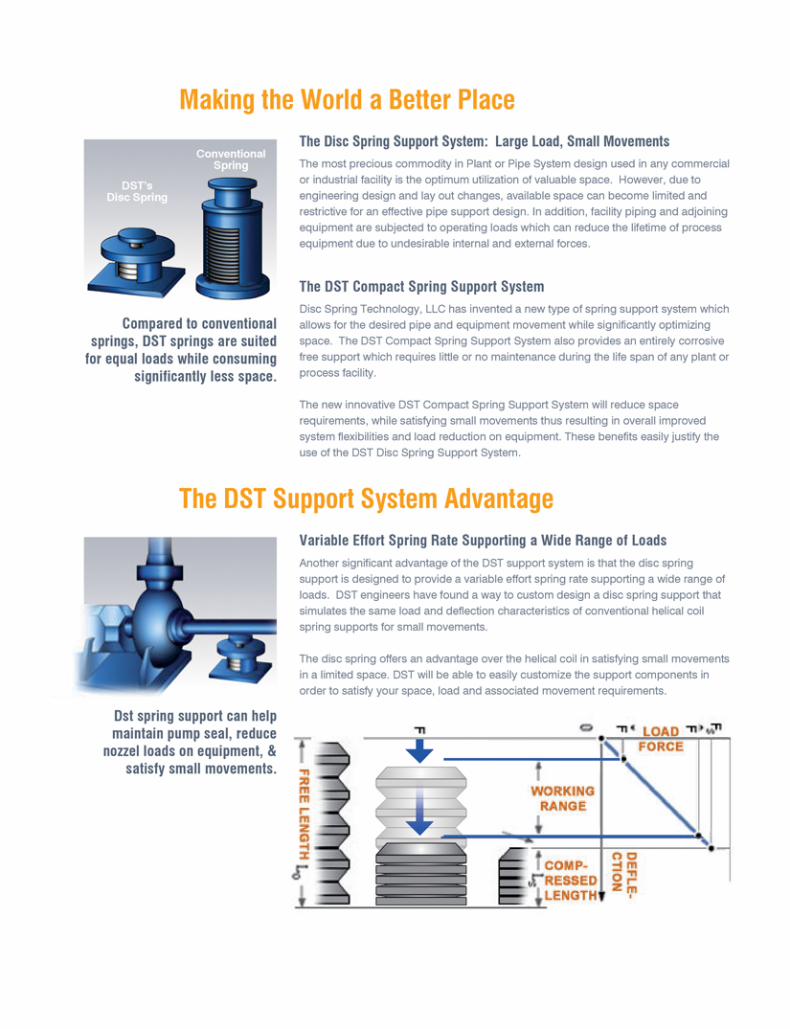
DST PRODUCT SOLUTIONS: Disc springs offer an advantage over helical coil springs in satisfying small displacements in limited space. By stacking conical springs and compressing them to a predetermined load, the DST Spring Support can effectively maintain support through an operating displacement in a minimum amount of space. By using conical springs, the height of a typical spring support can be reduced by 30% to 50% for displacements from 0 to 1/2”. Further, due to a shorter profile, the DST Spring Support is suitable for placement under equipment such as pumps, turbines, compressor base plates, heat exchangers and equipment skids where a helical coil spring is impractical. To summarize the advantages of the DST Spring Support, the following features apply to its design:
1. The DST Spring Support satisfies small displacements of 0 to 3/4” within a minimum amount of space while effectively maintaining support of pipe or equipment within the piping system.
2. The entire DST Spring Support can be made with corrosion free materials by using
stainless steel (conical) springs, which require no maintenance during the life of the support. This offers a safer and more reliable support for the lifetime of the system.
3. The DST Spring Support is designed to maintain the 25% variability requirements of
MSS-SP58 ASME standard.
4. Leaks at pipe joints and equipment flange connections are reduced. 5. Excessive forces and moments on connected equipment such as pumps and turbines
are minimized meeting nozzle load requirements set by the equipment’s manufacturer. Excessive stresses on adjacent supporting and restraining elements are also minimized.
6. Extend equipment life by reducing costly equipment down time and maintenance.
7. Deflection and load characteristics can be changed in the spring support by stacking
disc springs in series, parallel, or combinations of series and parallel. Various multiple stacking arrangements with different thicknesses can be made depending on the load requirements. This is ideal for unique situations where loads and movement requirements demand a stiffer or softer spring than is normally offered.
Patent Pending, All Rights Reserved. 4
Compared to Helical Springs: The geometry of the equipment nozzle on many different pieces of equipment demands the use of a compact spring support. The DST spring will support the same load through the same range of movement up to 3/4” as the helical coil spring support in a substantially smaller space. DST supports can be made for custom applications by changing the number of disc spring washers to meet the specified movement making it as short and inexpensive as possible. Helical coil spring supports do not offer this benefit particularly at smaller displacements as their lengths can not be cut to specific movements. This cost benefit can be considerably appreciable when stainless steel is concerned in conjunction with large loads. To illustrate the difference between helical coil springs and conical washers, the minimum height of a helical coil spring could be limited to the distance of one times the pitch of the helical coil plus one coil rod diameter. This height would be greater than the height of one conical washer. The helical coil spring would have less load carrying capability than a conical washer having less height. The helical coil spring force would be weak as its spring constant is dependent on its length or the amount it can compress. One can not obtain the high load settings required for small displacements simply by making the spring shorter. Its spring constant, by definition, is pounds per inch of compression, which means the spring constant for a helical coil spring is linear. Its working range could not encompass the 25% variability requirement of the MSS-SP58 standard practice; which is a requirement set by the ASME code for pressure piping. In contrast, the conical washer’s load deflection characteristics are variable throughout its load range. Because of its conical shape and design, the conical washer has a variable load deflection that is stiff in the pre-loaded position but acts similar to the helical coil spring’s linear spring constant as it moves through its working range. Both deflection characteristics can be observed from the graphs presented in section 4. The following is one example of a situation that requires the need of a compact spring support; Plate and frame heat exchangers as described in the API 662 standard emphasizes the requirement of nozzle loading being kept to a minimum. Nozzles on load sensitive equipment are often located, by design, close to grade elevation and are obscured by obstructions such as platforms and other equipment. See Illustration on page 7. Typically on a plate and frame exchanger, 4 nozzles exist – 2 inlet nozzles and 2 outlet nozzles. The 2 nozzles at the bottom are typically one pipe diameter (at the bottom of the pipe) in distance above the top of the exchanger’s foundation. The allowable load for an eight-inch inlet nozzle or outlet nozzle of an API 662 standard service nozzle is 246 lbs. of force with a 911 lb-ft moment. Piping systems usually contain reducers connecting to the heat exchanger making the piping larger than the nozzle size of the exchanger. The weight alone of this piping and its fluid is almost always greater than the allowable load capacity that is specified by the code. A spring support is, obviously, required. The room for the spring support makes installation a challenge due to restricted space. A DST Spring is more suitable for direct installation in the limited space provided under the heat exchanger’s lower nozzles.
Patent Pending, All Rights Reserved. 11
SPRING SUPPORT SELECTION TABLES Pages 16 and 17 include the Carbon Steel Selection Table while pages 18 and 19 include the Stainless Steel Selection Table. Describing the selection tables, the size is listed across the top row of each table. The movement for each size is shown in the columns at the left of the tables. (Note that there are five separate movement (or deflection) categories; each deflection category corresponds to the specific Figure Number:
1) Figure 125 - Supports that will satisfy movements up to (1/8”), 2) Figure 250 - Supports that will satisfy movements up to (1/4”), 3) Figure 375 - Supports that will satisfy movements up to (3/8”), 4) Figure 500 - Supports that will satisfy movements up to (1/2”), 5) Figure 750 - Supports that will satisfy movements up to (3/4”).
The corresponding operating and installed loads are listed from the top left to the lower right of each table within the columns for each size. The Effective Spring Rate Formula and Variability Rate Formula are provided below the spring selection table. Effective Spring Rate = |Operating Load (lbs.) - Installed Load (lbs.)|/ Movement (in.) The % Variability = 100|(Operating Load - Installed Load)|/Operating Load HOW TO SELECT A HANGER USING THE TABLE The movement (displacement magnitude and direction up or down) from installed load (cold load) to operating load (hot load) must be known. The operating load (the actual weight of the piping) which the spring is to support must also be known. The Installed load (cold load), Figure Number, and size need to be selected. The conical washer spring rate is very close to linear, but it is not completely linear as indicated in the included graphs. The factors A, B, C, D, E, & F are provided for each spring’s size. The factors A, B, & C are independent of the Figure Number. These are used to calculate loads for each Figure Number. The factors D, E, & F are based on Figure Number 250. These factors are used for calculating travel. The calculated travel must be divided by the Figure Number’s Travel Factor. The Travel Factor for Figure Number 125 is 0.5. The Travel Factors for Figure Numbers 125, 250, 375, 500 & 750 are 0.5, 1, 1.5, 2 & 3 respectively. These factors, along with the equations provided, are used to calculate Y (the installed load) for any movement X determining the support Figure Number and size. No interpolation is required. Find the operating load in the working range shown in the Spring Selection Table. If the operating load is outside the working range of the hanger selected, choose the operating load in the next larger size.
Patent Pending, All Rights Reserved. 12
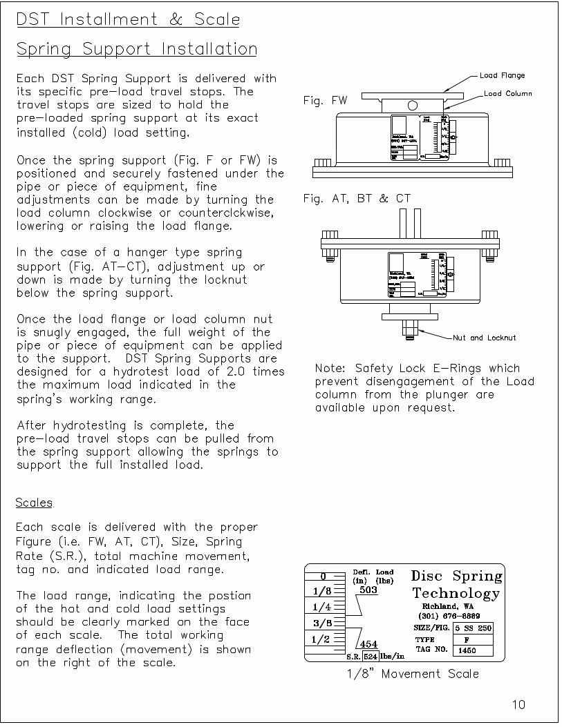
To determine the installed load, read the spring scale, up or down, for the expected movement. The spring selection table is read in the opposite direction from the expected movement. The load arrived is the installed load. Selection is complete when the operating load and installed load are both within the working range of the selected size. The Spring Selection Table shows only loads within the working range. If a hanger is not available for the requirements within that working range, select a Figure Number with a wider range. The check for MSS SP-58 25% variability is then required. See complete numeric examples below. The “Takeout”, indicated in the Spring Support Figures & Types section drawings as Length “X” Min. and Length “X” Max., starts at the beginning of the spring’s working range for 0” deflection. The amount of adjustment to bring the spring support to its installed “Takeout” will be demonstrated in the following examples. To simplify this process, an automatic selection program is available for selecting both stainless or carbon steel supports at www.dstechnologyllc.com. Example 1: Carbon Steel Material Given: Operating load = 276 lbs. load @ movement = 0.188” up installed to operating Find the operating load using the selection table or graphs.
1. The first figure number that can envelope a movement = 0.188” is a Figure Number 250 with a travel factor of 2.0.
2. The operating load of 276 Lbs. is first available in size 3CS. 3. The factors for that spring size 3CS are given as: A = -260.024, B = 744.68, C =
23.68, D = 1.70 x 10⁻⁶, E = 9.24 x 10⁻⁴, F = 7.95 x 10⁻³. 4. Spring size 3CS is initially compressed to (X0) = 0.2788” to begin its working range
at (Y0) = 211 lbs. initial load. 5. The operating load of Y = 276 lbs. load is found to be compressed to (XP) = 0.393”
(using X = (DY2 + EY + F) with the factors D, E, & F for that Spring Size 3CS). 6. The movement from the installed load to the operating load is 0.188” up. 7. The total movement (XI) = 0.393” + (0.188” divided by a travel factor of 2.0) =
0.487”. 8. The installed load for the total movement (XI) = 0.487” is found to be (YI) = 324.4
lbs. (using Y = (AX2+ BX +C) with the factors A, B, & C for that Spring Size 3CS.) 9. The Figure Number 250 can envelope that working range of 324.42 lbs. installed
load to 276 lbs. operating load @ movement = 0.188” up installed to operating. 10. The % Variability = 100 x | (operating load - installed load) | / operating load. The
% Variability = 100 x | (276 Lbs. -324.4 lbs.) | / 276 lbs. = 17.54% < 25% Selection complete (MSS SP-58 satisfied).
11. Effective Spring Rate = | (operating load - installed load) | / |movement Effective Spring Rate = | (276 lbs.-324.4 lbs.) | / |.188 in.| = 324.42 lbs./in.
12. The adjustment for the installed “Takeout” is found to be = 0.766” using (DYI
2 + EYI + F) + (X0) with the factors D, E, F, & X0 for that spring size.
Patent Pending, All Rights Reserved. 13
Example 2: Carbon Steel Material Given: Operating load = 400 lbs. load @ movement = 0.22” up installed to operating Find the operating load using the selection table or graphs.
1. The first figure number that can envelope a movement =0.22” is a Figure Number 250 with a travel factor of 2.0.
2. The operating load of 400 lbs. is first available in size 4CS. 3. The factors for that Spring Size 4CS are given as: A -334.939, B = 964.66, C = 30.78,
D = 1.01x10⁻⁶, E = 7.14 x 10⁻⁴, F = 7.99 x 10⁻³. 4. Spring Size 4CS is initially compressed to (X0) =0.2803” to begin its working range
at (Y0) = 275 lbs. initial load. 5. The operating load of Y = 400 Lbs. Load is found to be compressed to (XP) = 0.4549”
(using X = (DY2 + EY + F) with the factors D, E, & F for that Spring Size 4CS). 6. The movement from the installed load to the operating load is 0.22” up. 7. The total movement (XI) = 0.4549” + (0.22” divided by a travel factor of 2.0) =
0.5649”. 8. The installed load for the total movement (XI) = .5649” is found to be (YI) = 468.85
lbs. (using Y = (AX2 + BX + C) with the factors A, B, & C for that Spring Size 4CS). 9. The Figure Number 250 can NOT envelope that working range of 468.85 lbs.
installed load to 400 lbs. operating load @ movement = 0.22” up installed to operating .
10. Go to a next larger size spring as the operating load of 400 Lbs. is also available in size 5CS. As already stated, Figure Number 250 with a travel factor of 2.0 can envelope the movement.
11. The factors for that Spring Size 5CS are given as: A -449.197, B = 1273.389, C = 39.99, D = 5.88 x 10⁻⁷, E = 5.41 x 10⁻⁴, F = 7.86 x 10⁻³.
12. Spring Size 5CS is initially compressed to (X0) = 0.2759” to begin its working range at (Y0) = 357 lbs. initial load.
13. The operating load of Y = 400 lbs. load is found to be compressed to (XP) = 0.3183” (using X = (DY2 + EY + F) with the factors D, E, & F for that Spring Size 4CS).
14. The movement from the installed load to the operating load is 0.22” up. 15. The total movement (XI) = 0.3183” + (0.22” divided by a travel factor of 2.0) =
0.4283”. 16. The installed load for the total movement (XI) = 0. 4283” is found to be (YI) = 503.0
lbs. (using Y = (AX2 + BX + C) with the factors A, B, & C for that Spring Size 4CS).
Patent Pending, All Rights Reserved. 14
17. The Figure Number 250 can envelope that working range of 503.0 lbs. installed load
to 400 lbs. operating load @ movement = 0.22” up installed to operating. 18. The % Variability = 100 x | (operating load - installed load) | / operating load
The % Variability = 100 x | (400 lbs. -503.0 lbs.) | / 400 lbs. = 25.75% > 25% Selection incomplete (MSS SP-58 not satisfied).
19. The next figure number that can envelope a movement = 0.22” is a Figure Number 375 with a travel factor of 3.0.
20. The operating load of 400 lbs. is first available in size 4CS. 21. The factors for that Spring Size 4CS are given as: A -334.939, B = 964.66, C = 30.78,
D = 1.01 x 10⁻⁶, E = 7.14 x 10⁻⁴, F = 7.99 x 10⁻³. 22. Spring Size 4CS is initially compressed to (X0) =0.2803” to begin its working range
at (Y0) = 275 Lbs. initial load. 23. The operating load of Y = 400 lbs. load is found to be compressed to (XP) = 0.4549”
(using X = (DY2 + EY + F) with the factors D, E, & F for that Spring Size 4CS). 24. The movement from the installed load to the operating load is 0.22” up. 25. The total movement (XI) = 0.4549” + (0.22” divided by a travel factor of 3.0) =
0.5283”. 26. The installed load for the total movement (XI) = 0.5283” is found to be (YI) = 446.90
lbs. (using Y = (AX2 + BX + C) with the factors A, B, & C for that Spring Size 4CS). 27. The Figure Number 375 that can envelope that working range of 446.90lbs., installed
load to 400 lbs., operating load @ movement = 0.22” up installed to operating. 28. The % Variability = 100 x | (operating load - installed load) | / operating load
The % Variability = 100 x | (400 lbs. -446.90 lbs.) | / 400 lbs. = 11.73% < 25% Selection complete (MSS SP-58 satisfied).
29. Effective Spring Rate = | (operating load - installed load) | / |movement| Effective Spring Rate = | (400 lbs.-446.90 lbs.) | / |0.22 in.| = 213.2 lbs./in. 30. The adjustment for the installed “Takeout” is found to be = 0.809” using
(DYI 2+EYI +F)+ (X0) with the factors D, E, F, & X0 for that spring size.
Patent Pending, All Rights Reserved. 15
Example 3a: Carbon Steel Material Given: Operating load = 9763 lbs. load @ movement = -0.1339” down installed to operating Find the operating load using the selection table or graphs.
1. The first figure number that can envelope a movement = -0.1339” is a Figure Number 250 with a travel factor of 2.0.
2. The operating load of 9763 Lbs. is first available in size 16CS. 3. The factors for that Spring Size 16CS are given as: 4. A = -6648.879, B = 22592.177, C = 850.51, D = 1.56 x 10⁻⁹, E = 3.00 x 10⁻⁵, F = -9.43 x 10⁻³. 5. Spring Size 16CS is initially compressed to (X0) = 0.3308” to begin its working
range at (Y0) = 7596 lbs. initial load. 6. The operating load of Y = 9763 lbs. load is found to be compressed to (XP) =
0.4508” (using X = (DY2 + EY + F) with the factors D, E, & F for that Spring Size 16CS).
7. The movement from the installed load to the operating load is -0.1339” down. 8. The total movement (XI) = 0.4508” + (-0.1339” divided by a travel factor of 2.0.) =
0.3839”. 9. The installed load for the total movement (XI) = 0.3839” is found to be (YI) =
8543.58 lbs. (using Y = (AX2 + BX + C) with the factors A, B, & C for that Spring Size 16CS).
10. The Figure Number 250 can envelope that working range of 8543.58 lbs. installed load to 9763 lbs. operating load @ movement = -0.1339” down installed to operating.
11. The % Variability = 100 x | (operating load - installed load) | / operating load. The % Variability = 100 x | (9763 lbs. -8543.58 lbs.) | / 9763 lbs. = 12.49% < 25% Selection complete (MSS SP-58 satisfied).
12. Effective Spring Rate = | (operating load - installed load) | / |movement| Effective Spring Rate = | (9763 lbs.-8543.58 lbs.) | / |-0.1339 in.| = 9106.95 lbs./in.
13. The adjustment for the installed “Takeout” is found to be = 0.710” using (DYI
2 + EYI + F)+ (X0) with the factors D, E, F, & X0 for that spring size.
Patent Pending, All Rights Reserved. 16
Example 3b: Carbon Steel Material The purpose of this example is to show how a special purpose support can be made out of a range support to save space. The requirements of this example are the same as Example 3a.
1. As shown in Example 3a, the first figure number that can envelope a movement = -0.1339” is a Figure Number 250 with a travel factor of 2.0. This is the starting point for a special purpose support. The special purpose support will be between a Figure Number 250 and a Figure Number 125. The Figure Number 250, size 16CS has 6 disc springs and the Figure Number 125, size 16CS has 3 disc springs. This is an example with 4 springs. The Figure Number 250 travel factor of 2.0 is adjusted by that ratio of 4 divided by 6 (=0.667). The Travel Factor of 1.334 is now applied to Example 3a
2. Same as Example 3a. 3. Same as Example 3a 4. Same as Example 3a 5. Same as Example 3a 6. Same as Example 3a 7. Same as Example 3a 8. The total movement (XI) = 0.4508” + (-0.1339” divided by a travel factor of 1.334.) =
0.3505” 9. The installed load for the total movement (XI) = 0.3505” is found to be (YI) =
7951.64 lbs. (using Y = (AX2 + BX + C) with the factors A, B, & C for that Spring Size 16CS).
10. The Figure Number 250 with a travel factor of 1.334 can envelope that working range of 7951.64 lbs. installed load to 9763 lbs. operating load @ movement = -0.1339” down installed to operating.
11. The % Variability = 100 x | (operating load - installed load) | / operating load The % Variability = 100 x | (9763 lbs. -7951.64lbs.) | / 9763 lbs. = 18.55% < 25% Selection complete (MSS SP-58 satisfied).
12. Effective Spring Rate = | (operating load - installed load) | / |movement| Effective Spring Rate = | (9763 lbs.-7951.64 lbs.) | / |-0.1339 in.| = 13527.69 lbs./in.
13. Note that this spring support is 1.1875” shorter than the support with 6 springs as described in Example 3a above for Figure Number 250 size 16CS. (Any movement can be accommodated upon special request.)
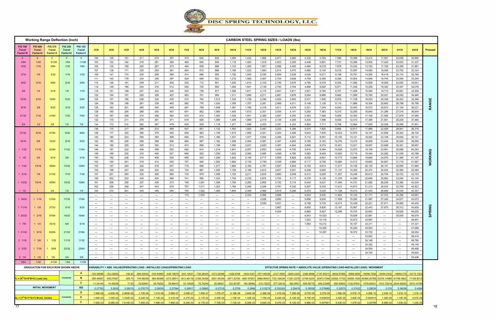
FIG 750 Travel Factor=6
FIG 500 Travel Factor=4
FIG 375 Travel Factor=3
FIG 250 Travel Factor=2
FIG 125 Travel Factor=1
1CS 2CS 3CS 4CS 5CS 6CS 7CS 8CS 9CS 10CS 11CS 12CS 13CS 14CS 15CS 16CS 17CS 18CS 19CS 20CS 21CS 22CS Preload
0 0 0 0 0 100 129 161 211 275 357 474 632 830 1,094 1,432 1,882 2,477 3,260 4,332 5,762 7,596 10,099 13,214 17,091 22,636 30,990
3/64 1/32 3/128 1/64 1/128 103 132 164 216 281 365 484 645 849 1,118 1,463 1,919 2,523 3,330 4,408 5,891 7,737 10,266 13,505 17,425 23,023 31,437
3/32 1/16 3/64 1/32 1/64 105 135 168 220 287 373 494 659 868 1,143 1,493 1,957 2,568 3,400 4,484 6,018 7,878 10,432 13,793 17,758 23,409 31,881
107 138 171 225 293 381 504 672 886 1,168 1,523 1,993 2,614 3,470 4,560 6,145 8,018 10,597 14,080 18,089 23,793 32,324
3/16 1/8 3/32 1/16 1/32 109 141 174 230 299 389 514 686 905 1,192 1,553 2,030 2,659 3,539 4,635 6,271 8,158 10,761 14,365 18,418 24,174 32,765
111 143 178 234 305 397 524 699 923 1,216 1,583 2,067 2,704 3,608 4,709 6,395 8,296 10,924 14,648 18,745 24,554 33,204
9/32 3/16 9/64 3/32 3/64 114 146 181 239 311 404 534 712 941 1,240 1,612 2,103 2,749 3,676 4,784 6,519 8,434 11,086 14,929 19,069 24,932 33,641
116 149 185 243 316 412 544 725 959 1,264 1,641 2,139 2,793 3,744 4,858 6,642 8,571 11,248 15,208 19,392 25,307 34,076
3/8 1/4 3/16 1/8 1/16 118 151 188 247 322 420 553 738 977 1,288 1,671 2,175 2,837 3,811 4,931 6,765 8,707 11,409 15,485 19,713 25,681 34,509
120 154 191 252 328 427 563 751 995 1,311 1,699 2,211 2,881 3,878 5,004 6,886 8,842 11,569 15,760 20,031 26,052 34,940
15/32 5/16 15/64 5/32 5/64 122 157 195 256 334 435 572 764 1,013 1,335 1,728 2,246 2,925 3,945 5,077 7,006 8,976 11,728 16,033 20,348 26,422 35,369
124 159 198 261 339 442 582 776 1,030 1,358 1,757 2,281 2,968 4,011 5,149 7,126 9,110 11,886 16,304 20,663 26,789 35,796
9/16 3/8 9/32 3/16 3/32 126 162 201 265 345 449 591 789 1,048 1,381 1,785 2,316 3,011 4,076 5,221 7,245 9,243 12,043 16,573 20,975 27,154 36,221
128 165 204 269 350 457 601 802 1,065 1,404 1,813 2,351 3,054 4,141 5,292 7,363 9,375 12,200 16,840 21,286 27,518 36,644
21/32 7/16 21/64 7/32 7/64 130 167 208 274 356 464 610 814 1,082 1,426 1,841 2,385 3,097 4,205 5,363 7,480 9,506 12,355 17,106 21,595 27,879 37,065
132 170 211 278 361 471 619 826 1,099 1,449 1,869 2,419 3,139 4,269 5,434 7,596 9,636 12,510 17,369 21,901 28,238 37,484
3/4 1/2 3/8 1/4 1/8 134 172 214 282 367 478 628 839 1,116 1,471 1,896 2,453 3,181 4,333 5,504 7,711 9,766 12,664 17,630 22,206 28,595 37,901
136 175 217 286 372 485 637 851 1,132 1,493 1,923 2,487 3,223 4,396 5,574 7,825 9,895 12,817 17,889 22,509 28,951 38,316
27/32 9/16 27/64 9/32 9/64 138 177 220 290 378 492 646 863 1,149 1,515 1,950 2,521 3,264 4,459 5,643 7,939 10,023 12,970 18,147 22,809 29,304 38,730
140 180 223 294 383 499 655 875 1,166 1,537 1,977 2,554 3,306 4,521 5,712 8,051 10,150 13,121 18,402 23,108 29,655 39,141
15/16 5/8 15/32 5/16 5/32 142 182 226 298 388 506 664 887 1,182 1,558 2,004 2,587 3,347 4,583 5,780 8,163 10,276 13,272 18,655 23,404 30,004 39,550
144 185 229 302 393 513 673 898 1,198 1,580 2,031 2,620 3,387 4,644 5,848 8,274 10,401 13,421 18,907 23,699 30,351 39,957
1 1/32 11/16 33/64 11/32 11/64 146 187 232 306 399 520 682 910 1,214 1,601 2,057 2,653 3,428 4,705 5,916 8,384 10,526 13,570 19,156 23,991 30,696 40,363
148 189 235 310 404 527 690 922 1,230 1,622 2,083 2,685 3,468 4,765 5,983 8,493 10,650 13,718 19,404 24,282 31,039 40,766
1 1/8 3/4 9/16 3/8 3/16 150 192 238 314 409 534 699 933 1,246 1,643 2,109 2,717 3,508 4,825 6,050 8,601 10,773 13,866 19,649 24,570 31,380 41,167
152 194 241 318 414 540 707 945 1,262 1,664 2,135 2,749 3,548 4,884 6,117 8,708 10,895 14,012 19,893 24,857 31,719 41,567
1 7/32 13/16 39/64 13/32 13/64 153 197 244 322 419 547 716 956 1,277 1,684 2,160 2,781 3,587 4,943 6,183 8,814 11,017 14,158 20,135 25,141 32,055 41,964
155 199 247 326 424 553 724 967 1,292 1,705 2,185 2,812 3,627 5,001 6,248 8,920 11,137 14,302 20,374 25,424 32,390 42,360
1 5/16 7/8 21/32 7/16 7/32 157 201 250 330 429 560 733 979 1,308 1,725 2,211 2,843 3,665 5,059 6,313 9,025 11,257 14,446 20,612 25,704 32,723 42,753
159 203 253 334 434 566 741 990 1,323 1,745 2,235 2,874 3,704 5,117 6,378 9,128 11,376 14,589 20,848 25,983 33,054 43,145
1 13/32 15/16 45/64 15/32 15/64 161 206 256 337 439 573 749 1,001 1,338 1,765 2,260 2,905 3,742 5,174 6,443 9,231 11,494 14,731 21,082 26,259 33,382 43,534
162 208 258 341 443 579 757 1,011 1,353 1,784 2,285 2,936 3,781 5,230 6,507 9,333 11,612 14,873 21,313 26,534 33,709 43,922
1 1/2 1 3/4 1/2 1/4 164 210 261 345 448 585 765 1,022 1,368 1,804 2,309 2,966 3,818 5,286 6,570 9,434 11,728 15,013 21,543 26,806 34,034 44,307
--- --- --- --- --- --- 773 1,033 --- --- 2,333 2,996 3,856 --- 6,633 9,535 11,844 15,153 21,771 27,076 34,356 44,691
1 19/32 1 1/16 51/64 17/32 17/64 --- --- --- --- --- --- --- --- --- --- --- 3,026 3,893 --- 6,696 9,634 11,959 15,292 21,997 27,345 34,677 45,072
--- --- --- --- --- --- --- --- --- --- --- 3,056 3,931 --- 6,758 9,733 12,073 15,429 22,221 27,611 34,995 45,452
1 11/16 1 1/8 27/32 9/16 9/32 --- --- --- --- --- --- --- --- --- --- --- --- 3,967 --- 6,820 9,830 12,187 15,567 22,443 27,875 35,312 45,830
--- --- --- --- --- --- --- --- --- --- --- --- 4,004 --- 6,882 9,927 12,299 15,703 22,663 --- 35,626 46,205
1 25/32 1 3/16 57/64 19/32 19/64 --- --- --- --- --- --- --- --- --- --- --- --- --- --- 6,943 10,023 --- 15,838 22,881 --- 35,939 46,579
--- --- --- --- --- --- --- --- --- --- --- --- --- --- 7,003 10,118 --- 15,973 23,097 --- --- 46,951
1 7/8 1 1/4 15/16 5/8 5/16 --- --- --- --- --- --- --- --- --- --- --- --- --- --- 7,064 10,212 --- 16,107 23,311 --- --- 47,321
--- --- --- --- --- --- --- --- --- --- --- --- --- --- --- 10,305 --- 16,240 23,523 --- --- 47,688
1 31/32 1 5/16 63/64 21/32 21/64 --- --- --- --- --- --- --- --- --- --- --- --- --- --- --- 10,397 --- 16,372 23,733 --- --- 48,054
--- --- --- --- --- --- --- --- --- --- --- --- --- --- --- --- --- --- 23,942 --- --- 48,418
2 1/16 1 3/8 1 1/32 11/16 11/32 --- --- --- --- --- --- --- --- --- --- --- --- --- --- --- --- --- --- 24,148 --- --- 48,780
--- --- --- --- --- --- --- --- --- --- --- --- --- --- --- --- --- --- 24,352 --- --- 49,140
2 5/32 1 7/16 1 5/64 23/32 23/64 --- --- --- --- --- --- --- --- --- --- --- --- --- --- --- --- --- --- 24,554 --- --- 49,498
--- --- --- --- --- --- --- --- --- --- --- --- --- --- --- --- --- --- 24,755 --- --- 49,854
2 1/4 1 1/2 1 1/8 3/4 3/8 --- --- --- --- --- --- --- --- --- --- --- --- --- --- --- --- --- --- --- --- --- 50,208
3/64 1/32 3/128 1/64 1/128
A -124.54696 -154.23856 -192.64 -260.02044 -334.93885 -449.19679 -543.12631 -736.28445 -1073.52088 -1426.9768 -1633.0357 -1871.94236 -2147.4593 -3849.4345 -3380.9698 -7197.60215 -6648.87869 -6906.0656 -16099.7558 -16494.0332 -16692.076 -16170.1053
B 355.48567 449.21667 559.74 744.68249 964.66366 1273.38911 1613.48118 2168.24028 3001.54339 3971.32792 4861.87601 5966.90451 7331.58334 11261.2278 12166.5224 20473.7358 22592.17725 26550.1829 46369.20768 53376.14989 61795.4862 71165.9312
C 11.24144 14.49538 17.93 23.62901 30.78202 39.99415 53.10529 70.74244 92.98001 122.45187 160.36992 210.72522 277.32016 364.9937 485.06779 645.23388 850.50833 1130.87641 1479.62231 1913.72019 2534.62653 3470.10196
XO 0.27783 0.2835 0.28215 0.278775 0.28035 0.27594 0.28917 0.28665 0.27216 0.2709 0.2898 0.310275 0.332325 0.28476 0.35028 0.276885 0.33075 0.37422 0.28035 0.315 0.36036 0.4284
D 7.49E-06 4.60E-06 2.960E-06 1.70E-06 1.01E-06 5.88E-07 3.49E-07 1.95E-07 1.07E-07 6.16E-08 3.84E-08 2.38E-08 1.47E-08 7.28E-09 5.07E-09 2.27E-09 1.56E-09 9.97E-10 4.36E-10 2.93E-10 1.91E-10 1.21E-10
E 1.94E-03 1.53E-03 1.234E-03 9.24E-04 7.14E-04 5.41E-04 4.27E-04 3.17E-04 2.29E-04 1.73E-04 1.42E-04 1.15E-04 9.40E-05 6.10E-05 5.70E-05 0.000034 3.00E-05 2.60E-05 0.000015 1.30E-05 1.10E-05 9.67E-06
F 7.92E-03 8.08E-03 7.814E-03 7.95E-03 7.99E-03 7.86E-03 8.24E-03 8.17E-03 7.76E-03 7.72E-03 8.26E-03 8.84E-03 9.47E-03 8.12E-03 9.98E-03 0.007891 9.43E-03 1.07E-02 0.00799 8.98E-03 1.03E-02 1.22E-02
17 18
Working Range Deflection (inch) CARBON STEEL SPRING SIZES / LOADS (lbs)
SPRING WORKING RANGE
INITIAL MOVEMENT
ConstantsXP = (Y2*D+Y*E+F) Mvmt. Inches
GRADUATION FOR EACH ROW SHOWN ABOVE
ConstantsYI = (X2*A+X*B+C) Load Lbs.
VARIABILITY = ABS. VALUE(OPERATING LOAD - INSTALLED LOAD)/OPERATING LOAD EFFECTIVE SPRING RATE = ABSOLUTE VALUE (OPERATING LOAD-INSTALLED LOAD) / MOVEMENT
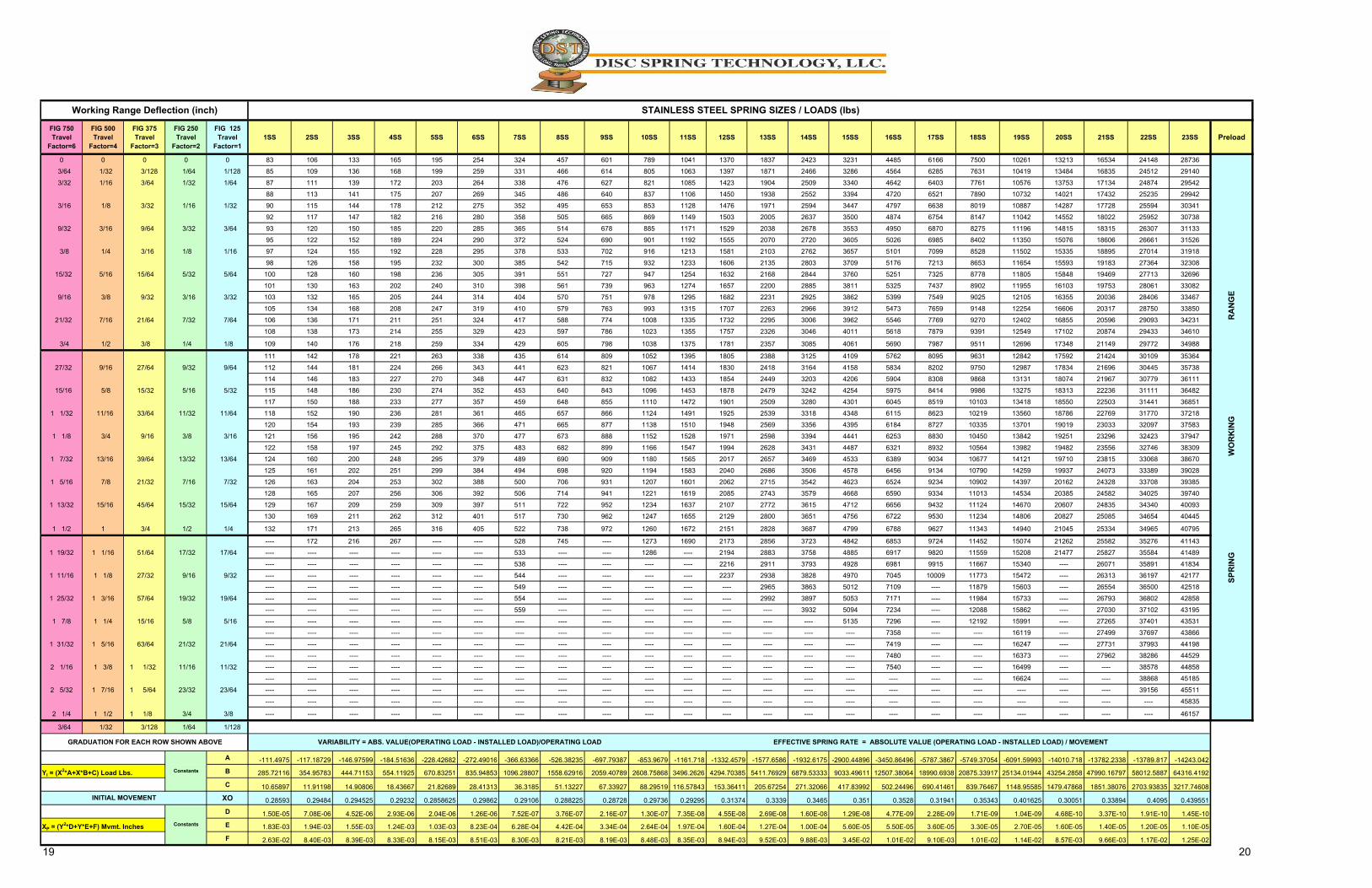
FIG 750 Travel Factor=6
FIG 500 Travel Factor=4
FIG 375 Travel Factor=3
FIG 250 Travel Factor=2
FIG 125 Travel Factor=1
1SS 2SS 3SS 4SS 5SS 6SS 7SS 8SS 9SS 10SS 11SS 12SS 13SS 14SS 15SS 16SS 17SS 18SS 19SS 20SS 21SS 22SS 23SS Preload
0 0 0 0 0 83 106 133 165 195 254 324 457 601 789 1041 1370 1837 2423 3231 4485 6166 7500 10261 13213 16534 24148 28736
3/64 1/32 3/128 1/64 1/128 85 109 136 168 199 259 331 466 614 805 1063 1397 1871 2466 3286 4564 6285 7631 10419 13484 16835 24512 29140
3/32 1/16 3/64 1/32 1/64 87 111 139 172 203 264 338 476 627 821 1085 1423 1904 2509 3340 4642 6403 7761 10576 13753 17134 24874 29542
88 113 141 175 207 269 345 486 640 837 1106 1450 1938 2552 3394 4720 6521 7890 10732 14021 17432 25235 29942
3/16 1/8 3/32 1/16 1/32 90 115 144 178 212 275 352 495 653 853 1128 1476 1971 2594 3447 4797 6638 8019 10887 14287 17728 25594 30341
92 117 147 182 216 280 358 505 665 869 1149 1503 2005 2637 3500 4874 6754 8147 11042 14552 18022 25952 30738
9/32 3/16 9/64 3/32 3/64 93 120 150 185 220 285 365 514 678 885 1171 1529 2038 2678 3553 4950 6870 8275 11196 14815 18315 26307 31133
95 122 152 189 224 290 372 524 690 901 1192 1555 2070 2720 3605 5026 6985 8402 11350 15076 18606 26661 31526
3/8 1/4 3/16 1/8 1/16 97 124 155 192 228 295 378 533 702 916 1213 1581 2103 2762 3657 5101 7099 8528 11502 15335 18895 27014 31918
98 126 158 195 232 300 385 542 715 932 1233 1606 2135 2803 3709 5176 7213 8653 11654 15593 19183 27364 32308
15/32 5/16 15/64 5/32 5/64 100 128 160 198 236 305 391 551 727 947 1254 1632 2168 2844 3760 5251 7325 8778 11805 15848 19469 27713 32696
101 130 163 202 240 310 398 561 739 963 1274 1657 2200 2885 3811 5325 7437 8902 11955 16103 19753 28061 33082
9/16 3/8 9/32 3/16 3/32 103 132 165 205 244 314 404 570 751 978 1295 1682 2231 2925 3862 5399 7549 9025 12105 16355 20036 28406 33467
105 134 168 208 247 319 410 579 763 993 1315 1707 2263 2966 3912 5473 7659 9148 12254 16606 20317 28750 33850
21/32 7/16 21/64 7/32 7/64 106 136 171 211 251 324 417 588 774 1008 1335 1732 2295 3006 3962 5546 7769 9270 12402 16855 20596 29093 34231
108 138 173 214 255 329 423 597 786 1023 1355 1757 2326 3046 4011 5618 7879 9391 12549 17102 20874 29433 34610
3/4 1/2 3/8 1/4 1/8 109 140 176 218 259 334 429 605 798 1038 1375 1781 2357 3085 4061 5690 7987 9511 12696 17348 21149 29772 34988
111 142 178 221 263 338 435 614 809 1052 1395 1805 2388 3125 4109 5762 8095 9631 12842 17592 21424 30109 35364
27/32 9/16 27/64 9/32 9/64 112 144 181 224 266 343 441 623 821 1067 1414 1830 2418 3164 4158 5834 8202 9750 12987 17834 21696 30445 35738
114 146 183 227 270 348 447 631 832 1082 1433 1854 2449 3203 4206 5904 8308 9868 13131 18074 21967 30779 36111
15/16 5/8 15/32 5/16 5/32 115 148 186 230 274 352 453 640 843 1096 1453 1878 2479 3242 4254 5975 8414 9986 13275 18313 22236 31111 36482
117 150 188 233 277 357 459 648 855 1110 1472 1901 2509 3280 4301 6045 8519 10103 13418 18550 22503 31441 36851
1 1/32 11/16 33/64 11/32 11/64 118 152 190 236 281 361 465 657 866 1124 1491 1925 2539 3318 4348 6115 8623 10219 13560 18786 22769 31770 37218
120 154 193 239 285 366 471 665 877 1138 1510 1948 2569 3356 4395 6184 8727 10335 13701 19019 23033 32097 37583
1 1/8 3/4 9/16 3/8 3/16 121 156 195 242 288 370 477 673 888 1152 1528 1971 2598 3394 4441 6253 8830 10450 13842 19251 23296 32423 37947
122 158 197 245 292 375 483 682 899 1166 1547 1994 2628 3431 4487 6321 8932 10564 13982 19482 23556 32746 38309
1 7/32 13/16 39/64 13/32 13/64 124 160 200 248 295 379 489 690 909 1180 1565 2017 2657 3469 4533 6389 9034 10677 14121 19710 23815 33068 38670
125 161 202 251 299 384 494 698 920 1194 1583 2040 2686 3506 4578 6456 9134 10790 14259 19937 24073 33389 39028
1 5/16 7/8 21/32 7/16 7/32 126 163 204 253 302 388 500 706 931 1207 1601 2062 2715 3542 4623 6524 9234 10902 14397 20162 24328 33708 39385
128 165 207 256 306 392 506 714 941 1221 1619 2085 2743 3579 4668 6590 9334 11013 14534 20385 24582 34025 39740
1 13/32 15/16 45/64 15/32 15/64 129 167 209 259 309 397 511 722 952 1234 1637 2107 2772 3615 4712 6656 9432 11124 14670 20607 24835 34340 40093
130 169 211 262 312 401 517 730 962 1247 1655 2129 2800 3651 4756 6722 9530 11234 14806 20827 25085 34654 40445
1 1/2 1 3/4 1/2 1/4 132 171 213 265 316 405 522 738 972 1260 1672 2151 2828 3687 4799 6788 9627 11343 14940 21045 25334 34965 40795
---- 172 216 267 ---- ---- 528 745 ---- 1273 1690 2173 2856 3723 4842 6853 9724 11452 15074 21262 25582 35276 41143
1 19/32 1 1/16 51/64 17/32 17/64 ---- ---- ---- ---- ---- ---- 533 ---- ---- 1286 ---- 2194 2883 3758 4885 6917 9820 11559 15208 21477 25827 35584 41489
---- ---- ---- ---- ---- ---- 538 ---- ---- ---- ---- 2216 2911 3793 4928 6981 9915 11667 15340 ---- 26071 35891 41834
1 11/16 1 1/8 27/32 9/16 9/32 ---- ---- ---- ---- ---- ---- 544 ---- ---- ---- ---- 2237 2938 3828 4970 7045 10009 11773 15472 ---- 26313 36197 42177
---- ---- ---- ---- ---- ---- 549 ---- ---- ---- ---- ---- 2965 3863 5012 7109 ---- 11879 15603 ---- 26554 36500 42518
1 25/32 1 3/16 57/64 19/32 19/64 ---- ---- ---- ---- ---- ---- 554 ---- ---- ---- ---- ---- 2992 3897 5053 7171 ---- 11984 15733 ---- 26793 36802 42858
---- ---- ---- ---- ---- ---- 559 ---- ---- ---- ---- ---- ---- 3932 5094 7234 ---- 12088 15862 ---- 27030 37102 43195
1 7/8 1 1/4 15/16 5/8 5/16 ---- ---- ---- ---- ---- ---- ---- ---- ---- ---- ---- ---- ---- ---- 5135 7296 ---- 12192 15991 ---- 27265 37401 43531
---- ---- ---- ---- ---- ---- ---- ---- ---- ---- ---- ---- ---- ---- ---- 7358 ---- ---- 16119 ---- 27499 37697 43866
1 31/32 1 5/16 63/64 21/32 21/64 ---- ---- ---- ---- ---- ---- ---- ---- ---- ---- ---- ---- ---- ---- ---- 7419 ---- ---- 16247 ---- 27731 37993 44198
---- ---- ---- ---- ---- ---- ---- ---- ---- ---- ---- ---- ---- ---- ---- 7480 ---- ---- 16373 ---- 27962 38286 44529
2 1/16 1 3/8 1 1/32 11/16 11/32 ---- ---- ---- ---- ---- ---- ---- ---- ---- ---- ---- ---- ---- ---- ---- 7540 ---- ---- 16499 ---- ---- 38578 44858
---- ---- ---- ---- ---- ---- ---- ---- ---- ---- ---- ---- ---- ---- ---- ---- ---- ---- 16624 ---- ---- 38868 45185
2 5/32 1 7/16 1 5/64 23/32 23/64 ---- ---- ---- ---- ---- ---- ---- ---- ---- ---- ---- ---- ---- ---- ---- ---- ---- ---- ---- ---- ---- 39156 45511
---- ---- ---- ---- ---- ---- ---- ---- ---- ---- ---- ---- ---- ---- ---- ---- ---- ---- ---- ---- ---- ---- 45835
2 1/4 1 1/2 1 1/8 3/4 3/8 ---- ---- ---- ---- ---- ---- ---- ---- ---- ---- ---- ---- ---- ---- ---- ---- ---- ---- ---- ---- ---- ---- 46157
3/64 1/32 3/128 1/64 1/128
A -111.4975 -117.18729 -146.97599 -184.51636 -228.42682 -272.49016 -366.63366 -526.38235 -697.79387 -853.9679 -1161.718 -1332.4579 -1577.6586 -1932.6175 -2900.44896 -3450.86496 -5787.3867 -5749.37054 -6091.59993 -14010.718 -13782.2338 -13789.817 -14243.042
B 285.72116 354.95783 444.71153 554.11925 670.83251 835.94853 1096.28807 1558.62916 2059.40789 2608.75868 3496.2626 4294.70385 5411.76929 6879.53333 9033.49611 12507.38064 18990.6938 20875.33917 25134.01944 43254.2858 47990.16797 58012.5887 64316.4192
C 10.65897 11.91198 14.90806 18.43667 21.82689 28.41313 36.3185 51.13227 67.33927 88.29519 116.57843 153.36411 205.67254 271.32066 417.83992 502.24496 690.41461 839.76467 1148.95585 1479.47868 1851.38076 2703.93835 3217.74608
XO 0.28593 0.29484 0.294525 0.29232 0.2858625 0.29862 0.29106 0.288225 0.28728 0.29736 0.29295 0.31374 0.3339 0.3465 0.351 0.3528 0.31941 0.35343 0.401625 0.30051 0.33894 0.4095 0.439551
D 1.50E-05 7.08E-06 4.52E-06 2.93E-06 2.04E-06 1.26E-06 7.52E-07 3.76E-07 2.16E-07 1.30E-07 7.35E-08 4.55E-08 2.69E-08 1.60E-08 1.29E-08 4.77E-09 2.28E-09 1.71E-09 1.04E-09 4.68E-10 3.37E-10 1.91E-10 1.45E-10
E 1.83E-03 1.94E-03 1.55E-03 1.24E-03 1.03E-03 8.23E-04 6.28E-04 4.42E-04 3.34E-04 2.64E-04 1.97E-04 1.60E-04 1.27E-04 1.00E-04 5.60E-05 5.50E-05 3.60E-05 3.30E-05 2.70E-05 1.60E-05 1.40E-05 1.20E-05 1.10E-05
F 2.63E-02 8.40E-03 8.39E-03 8.33E-03 8.15E-03 8.51E-03 8.30E-03 8.21E-03 8.19E-03 8.48E-03 8.35E-03 8.94E-03 9.52E-03 9.88E-03 3.45E-02 1.01E-02 9.10E-03 1.01E-02 1.14E-02 8.57E-03 9.66E-03 1.17E-02 1.25E-02
19 20
Working Range Deflection (inch) STAINLESS STEEL SPRING SIZES / LOADS (lbs)
INITIAL MOVEMENT
ConstantsXP = (Y2*D+Y*E+F) Mvmt. Inches
GRADUATION FOR EACH ROW SHOWN ABOVE
ConstantsYI = (X2*A+X*B+C) Load Lbs.
SPRING WORKING RANGE
VARIABILITY = ABS. VALUE(OPERATING LOAD - INSTALLED LOAD)/OPERATING LOAD EFFECTIVE SPRING RATE = ABSOLUTE VALUE (OPERATING LOAD - INSTALLED LOAD) / MOVEMENT
Patent Pending, All Rights Reserved. 21
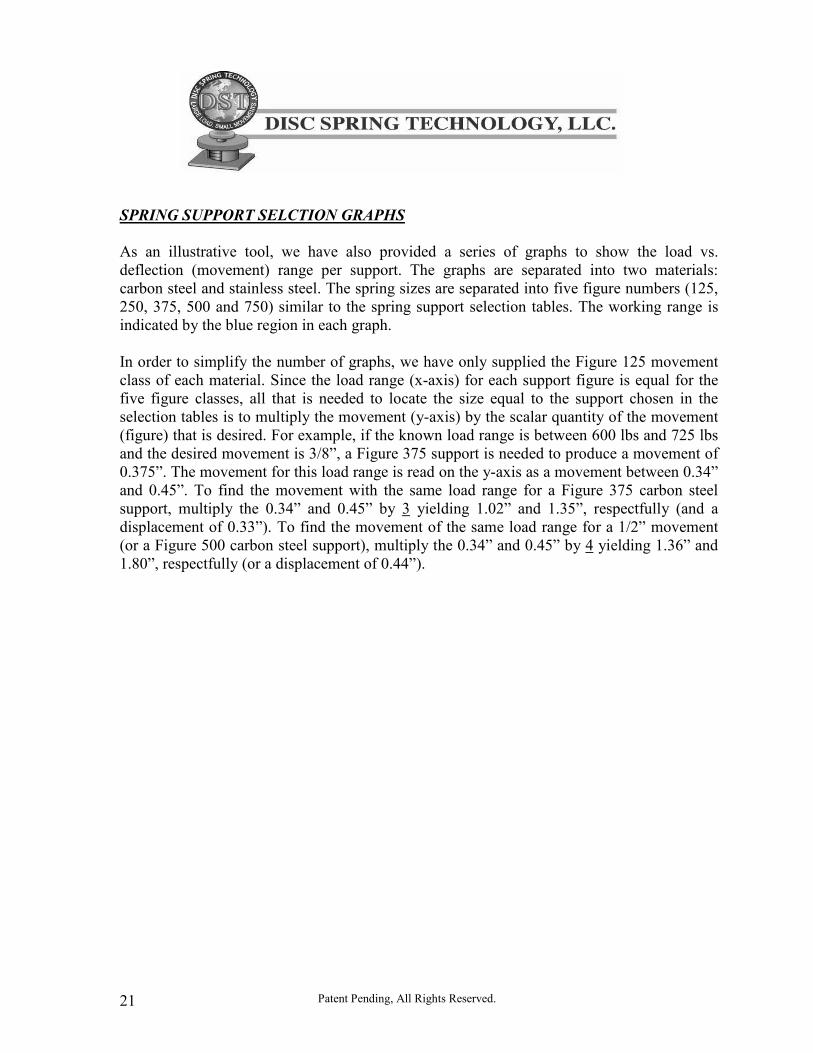
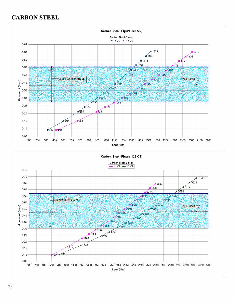
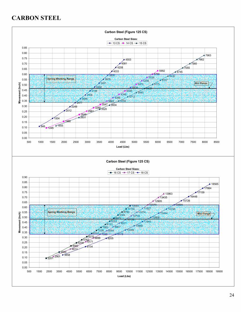
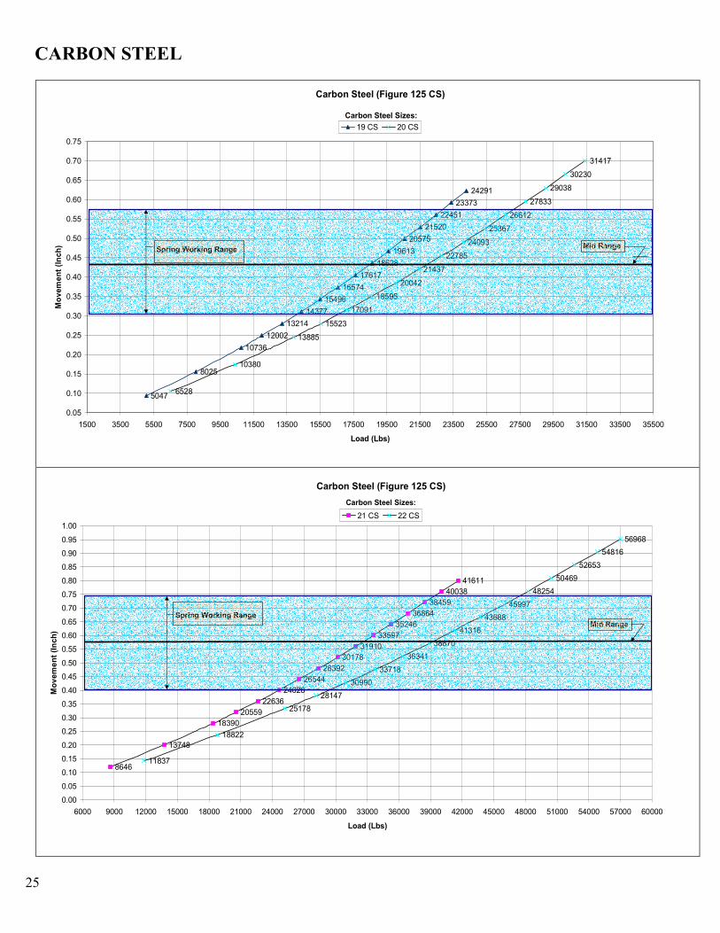
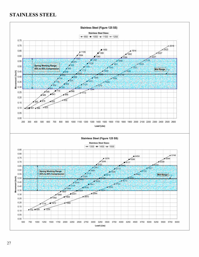
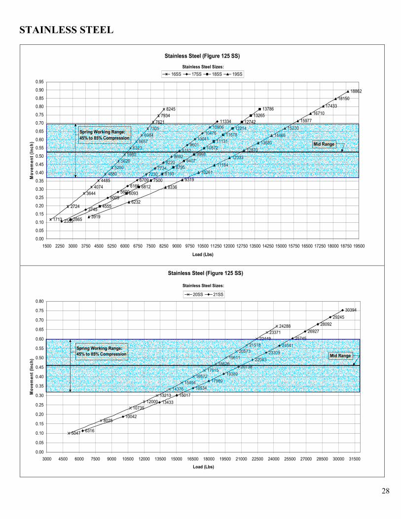
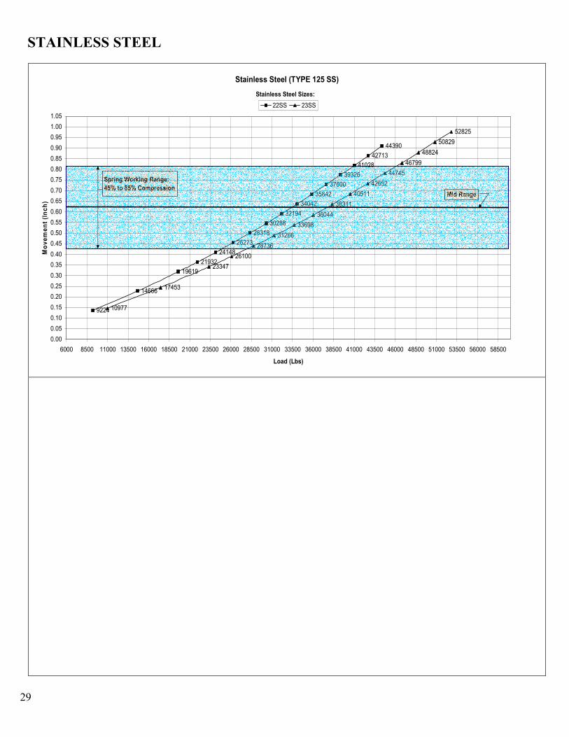
SPRING SUPPORT SELCTION GRAPHS As an illustrative tool, we have also provided a series of graphs to show the load vs. deflection (movement) range per support. The graphs are separated into two materials: carbon steel and stainless steel. The spring sizes are separated into five figure numbers (125, 250, 375, 500 and 750) similar to the spring support selection tables. The working range is indicated by the blue region in each graph. In order to simplify the number of graphs, we have only supplied the Figure 125 movement class of each material. Since the load range (x-axis) for each support figure is equal for the five figure classes, all that is needed to locate the size equal to the support chosen in the selection tables is to multiply the movement (y-axis) by the scalar quantity of the movement (figure) that is desired. For example, if the known load range is between 600 lbs and 725 lbs and the desired movement is 3/8”, a Figure 375 support is needed to produce a movement of 0.375”. The movement for this load range is read on the y-axis as a movement between 0.34” and 0.45”. To find the movement with the same load range for a Figure 375 carbon steel support, multiply the 0.34” and 0.45” by 3 yielding 1.02” and 1.35”, respectfully (and a displacement of 0.33”). To find the movement of the same load range for a 1/2” movement (or a Figure 500 carbon steel support), multiply the 0.34” and 0.45” by 4 yielding 1.36” and 1.80”, respectfully (or a displacement of 0.44”).
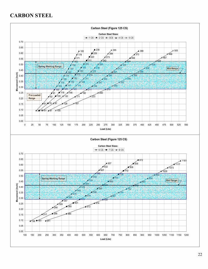
CARBON STEEL
22
Carbon Steel (Figure 125 CS)
38
61
82
91
100
109
118
126
134
142
149
156
163
171
178
185
49
79
105
118
129
141
152
162
173
182
192
202
211
220
229
238
61
97
130
146
161
175
188
201
214
226
238
250
262
273
284
295
81
128
171
192
211
230
247
265
281
297
313
329
344
359
373
388
105
167
223
250
275
299
322
345
366
388
408
428
448
467
486
505
0.00
0.05
0.10
0.15
0.20
0.25
0.30
0.35
0.40
0.45
0.50
0.55
0.60
0.65
0.70
0 25 50 75 100 125 150 175 200 225 250 275 300 325 350 375 400 425 450 475 500 525 550
Load (Lbs)
Movement (Inch)
1 CS 2 CS 3CS 4 CS 5 CS
Mid RangeSpring Working Range
Pre-Loaded Range
Carbon Steel Sizes:
Carbon Steel (Figure 125 CS)
136
217
290
324
357
389
419
448
476
504
530
556
582
607
632
657
181
288
385
431
474
516
556
595
632
669
704
738
772
806
839
872
241
384
513
574
632
687
741
792
842
891
938
984
1029
1073
1117
1161
0.00
0.05
0.10
0.15
0.20
0.25
0.30
0.35
0.40
0.45
0.50
0.55
0.60
0.65
0.70
100 150 200 250 300 350 400 450 500 550 600 650 700 750 800 850 900 950 1000 1050 1100 1150 1200
Load (Lbs)
Movement (Inch)
6 CS 7 CS 8 CS
Mid RangeSpring Working Range
Carbon Steel Sizes:
CARBON STEEL
23
Carbon Steel (Figure 125 CS)
317
504
675
754
830
903
974
1042
1107
1171
1232
1293
1352
1411
1469
1526
418
664
888
993
1094
1190
1282
1372
1458
1542
1623
1703
1781
1858
1934
2010
0.05
0.10
0.15
0.20
0.25
0.30
0.35
0.40
0.45
0.50
0.55
0.60
0.65
100 200 300 400 500 600 700 800 900 1000 1100 1200 1300 1400 1500 1600 1700 1800 1900 2000 2100 2200
Load (Lbs)
Movement (Inch)
9 CS 10 CS
Mid RangeSpring Working Range
Carbon Steel Sizes:
Carbon Steel (Figure 125 CS)
547
870
1164
1301
1432
1558
1680
1796
1909
2019
2126
2230
2332
2433
2533
2633
719
1143
1529
1709
1882
2048
2207
2360
2509
2653
2793
2930
3065
3197
3329
3459
0.05
0.10
0.15
0.20
0.25
0.30
0.35
0.40
0.45
0.50
0.55
0.60
0.65
0.70
0.75
100 250 400 550 700 850 1000 1150 1300 1450 1600 1750 1900 2050 2200 2350 2500 2650 2800 2950 3100 3250 3400 3550 3700
Load (Lbs)
Movement (Inch)
11 CS 12 CS
Mid Range
Spring Working Range
Carbon Steel Sizes:
CARBON STEEL
24
Carbon Steel (Figure 125 CS)
946
1504
2012
2249
2477
2695
2904
3106
3302
3491
3676
3856
4033
4208
4381
4553
1245
1980
2648
2961
3260
3547
38224088
4346
4595
48385075
5308
5538
5766
5992
1655
2631
3520
3934
4332
4713
5080
5433
5775
6107
6430
6745
7055
7360
7662
7963
0.00
0.05
0.10
0.15
0.20
0.25
0.30
0.35
0.40
0.45
0.50
0.55
0.60
0.65
0.70
0.75
0.80
0.85
500 1000 1500 2000 2500 3000 3500 4000 4500 5000 5500 6000 6500 7000 7500 8000 8500
Load (Lbs)
Movement (Inch)
13 CS 14 CS 15 CS
Mid Range
Spring Working Range
Carbon Steel Sizes:
Carbon Steel (Figure 125 CS)
2201
3500
46825234
57626270
67577228
76828123
85538972
93849790
1019210593
2901
4613
6171
6899
7596
8264
8907
9527
10126
10708
11274
11827
12370
12905
13435
13963
3858
6134
8205
9173
10099
10988
11843
12668
13464
14238
14990
15726
16448
17159
17864
18565
0.00
0.05
0.10
0.15
0.20
0.25
0.30
0.35
0.40
0.45
0.50
0.55
0.60
0.65
0.70
0.75
0.80
0.85
0.90
500 1500 2500 3500 4500 5500 6500 7500 8500 9500 10500 11500 12500 13500 14500 15500 16500 17500 18500 19500
Load (Lbs)
Movement (Inch)
16 CS 17 CS 18 CS
Mid RangeSpring Working Range
Carbon Steel Sizes:
CARBON STEEL
25
Carbon Steel (Figure 125 CS)
5047
8025
10736
12002
13214
14377
15496
16574
17617
18628
19613
20575
21520
22451
23373
24291
6528
10380
13885
15523
17091
18595
20042
21437
22785
24093
25367
26612
27833
29038
30230
31417
0.05
0.10
0.15
0.20
0.25
0.30
0.35
0.40
0.45
0.50
0.55
0.60
0.65
0.70
0.75
1500 3500 5500 7500 9500 11500 13500 15500 17500 19500 21500 23500 25500 27500 29500 31500 33500 35500
Load (Lbs)
Movement (Inch)
19 CS 20 CS
Mid RangeSpring Working Range
Carbon Steel Sizes:
Carbon Steel (Figure 125 CS)
8646
13748
18390
20559
22636
24628
26544
28392
30178
31910
33597
35246
36864
38459
40038
41611
11837
18822
25178
28147
30990
33718
36341
38870
41316
43688
45997
48254
50469
52653
54816
56968
0.00
0.05
0.10
0.15
0.20
0.25
0.30
0.35
0.40
0.45
0.50
0.55
0.60
0.65
0.70
0.75
0.80
0.85
0.90
0.95
1.00
6000 9000 12000 15000 18000 21000 24000 27000 30000 33000 36000 39000 42000 45000 48000 51000 54000 57000 60000
Load (Lbs)
Movement (Inch)
21 CS 22 CS
Mid RangeSpring Working Range
Carbon Steel Sizes:

STAINLESS STEEL
26
Stainless Steel (Figure125 SS)
32
51
68
76
83
90
97
103
110
116
121
127
132
138
143
148
41
65
86
97
106
116
125
133
142
150
158
166
173
181
188
196
51
81
108
121
133
145
156
167
177
188
198
207
217
226
235
245
63
100
134
150
165
179
193
207
220
232
244
256
268
280
291
303
0.00
0.05
0.10
0.15
0.20
0.25
0.30
0.35
0.40
0.45
0.50
0.55
0.60
0.65
0.70
20 35 50 65 80 95 110 125 140 155 170 185 200 215 230 245 260 275 290 305 320
Load (Lbs)
Movement (Inch)
1SS 2SS 3SS 4SS
Spring Working Range:45% to 85% Compression Mid Range
Stainless Steel Sizes:
Stainless Steel (Figure 125 SS)
74
118
158
177
195
212
229
244
260
275
289
304
317
331
345
358
97
154
206
230
254
276
298
318
338
358
377
395
413
431
449
466
124
197
264
295
324
353
380
407
432
457
481
505
528
551
574
596
174
277
371
415
457
497
535
573
609
644
678
711
744
776
808
839
0.00
0.05
0.10
0.15
0.20
0.25
0.30
0.35
0.40
0.45
0.50
0.55
0.60
0.65
0.70
20 50 80 110 140 170 200 230 260 290 320 350 380 410 440 470 500 530 560 590 620 650 680 710 740 770 800 830 860 890 920
Load (Lbs)
Movement (Inch)
5SS 6SS 7SS 8SS
Spring Working Range:45% to 85% Compression Mid Range
Stainless Steel Sizes:
STAINLESS STEEL
27
Stainless Steel (Figure 125 SS)
230
365
489
546
601
654
705
754
802
848
893
936
979
1022
1064
1105
301
479
641
716
789
858
925
989
1051
1112
1170
1228
1284
1340
1395
1450
398
632
846
946
1041
1133
1221
1306
1388
1468
1545
1621
1696
1769
1842
1914
523
832
1113
1244
1370
1490
1606
1718
1826
1931
2033
2133
2231
2327
2423
2518
0.00
0.05
0.10
0.15
0.20
0.25
0.30
0.35
0.40
0.45
0.50
0.55
0.60
0.65
0.70
0.75
200 300 400 500 600 700 800 900 1000 1100 1200 1300 1400 1500 1600 1700 1800 1900 2000 2100 2200 2300 2400 2500 2600
Load (Lbs)
Movement (Inch)
9SS 10SS 11SS 12SS
Spring Working Range:45% to 85% Compression Mid Range
Stainless Steel Sizes:
Stainless Steel (Figure 125 SS)
702
1116
1492
1668
1837
1998
2154
2304
2449
2589
2726
2860
2991
3121
3249
3376
926
1472
1969
2201
2423
2636
2841
3039
3230
3416
3596
3773
3946
4117
4286
4454
1259
1988
2643
2944
3231
3504
3764
4013
4252
4482
4705
4921
5132
5339
5544
5748
0.00
0.05
0.10
0.15
0.20
0.25
0.30
0.35
0.40
0.45
0.50
0.55
0.60
0.65
0.70
0.75
0.80
0.85
500 750 1000 1250 1500 1750 2000 2250 2500 2750 3000 3250 3500 3750 4000 4250 4500 4750 5000 5250 5500 5750 6000
Load (Lbs)
Movement (Inch)
13SS 14SS 15SS
Spring Working Range:45% to 85% Compression Mid Range
Stainless Steel Sizes:
STAINLESS STEEL
28
Stainless Steel (FIgure 125 SS)
1713
2724
3644
4074
4485
4880
5260
5626
5980
6323
6657
6984
7305
7621
7934
8245
2355
3745
50095600
6166
67097230
77348220
86929152
9601
1004110476
1090611334
2865
4555
6093
6812
7500
8160
8795
9407
9998
10572
11131
11678
12214
12742
13265
13786
3919
6232
8336
9319
10261
11164
12033
12870
13680
14465
15230
15977
16710
17433
18150
18862
0.00
0.05
0.10
0.15
0.20
0.25
0.30
0.35
0.40
0.45
0.50
0.55
0.60
0.65
0.70
0.75
0.80
0.85
0.90
0.95
1500 2250 3000 3750 4500 5250 6000 6750 7500 8250 9000 9750 10500 11250 12000 12750 13500 14250 15000 15750 16500 17250 18000 18750 19500
Load (Lbs)
Movement (Inch)
16SS 17SS 18SS 19SS
Spring Working Range:45% to 85% Compression
Mid Range
Stainless Steel Sizes:
Stainless Steel (Figure 125 SS)
5047
8025
10735
12000
13213
14376
15494
16572
17615
18626
19611
20573
21518
22449
23371
24288
6316
10042
13433
15017
16534
17989
19389
20738
22043
23309
24541
25745
26927
28092
29245
30394
0.00
0.05
0.10
0.15
0.20
0.25
0.30
0.35
0.40
0.45
0.50
0.55
0.60
0.65
0.70
0.75
0.80
3000 4500 6000 7500 9000 10500 12000 13500 15000 16500 18000 19500 21000 22500 24000 25500 27000 28500 30000 31500
Load (Lbs)
Movement (Inch)
20SS 21SS
Spring Working Range:45% to 85% Compression Mid Range
Stainless Steel Sizes:
STAINLESS STEEL
29
Stainless Steel (TYPE 125 SS)
9224
14666
19619
21932
24148
26273
28318
30288
32194
34042
35842
37600
39326
41028
42713
44390
10977
17453
23347
26100
28736
31266
33698
36044
38311
40511
42652
44745
46799
48824
50829
52825
0.00
0.05
0.10
0.15
0.20
0.25
0.30
0.35
0.40
0.45
0.50
0.55
0.60
0.65
0.70
0.75
0.80
0.85
0.90
0.95
1.00
1.05
6000 8500 11000 13500 16000 18500 21000 23500 26000 28500 31000 33500 36000 38500 41000 43500 46000 48500 51000 53500 56000 58500
Load (Lbs)
Movement (Inch)
22SS 23SS
Spring Working Range:45% to 85% Compression
Mid Range
Stainless Steel Sizes:
Patent Pending, All Rights Reserved. 30
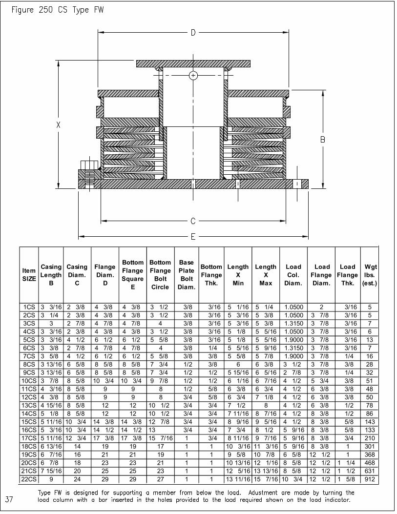
DST CARBON STEEL SPRING SUPPORT TYPES, FIGURES AND SIZES The overall dimensions of each figure type are provided in this section. DST Carbon Steel Spring Supports are divided into five displacement categories:
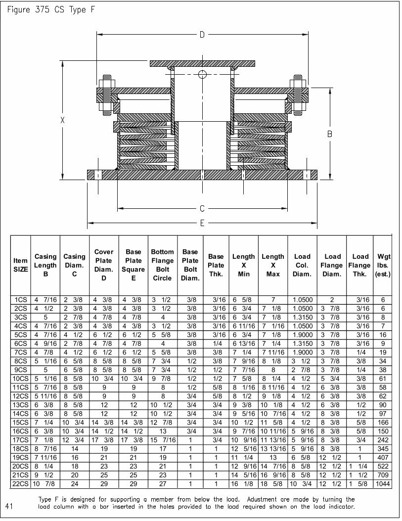
1) Figure 125 - Supports that will satisfy movements up to (1/8”), 2) Figure 250 - Supports that will satisfy movements up to (1/4”), 3) Figure 375 - Supports that will satisfy movements up to (3/8”), 4) Figure 500 - Supports that will satisfy movements up to (1/2”), 5) Figure 750 - Supports that will satisfy movements up to (3/4”).
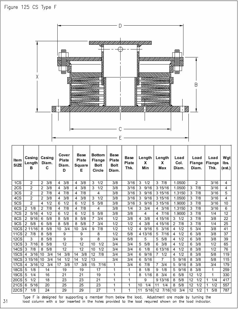
Item SIZE
Casing Length B
Casing Diam. C
Cover Plate Diam. D
Base Plate Square E
Bottom Flange Bolt Circle
Base Plate Bolt Diam.
Base Plate Thk.
Length X Min
Length X Max
Load Col. Diam.
Load Flange Diam.
Load Flange Thk.
Wgt lbs. (est.)
1CS 2 2 3/8 4 3/8 4 3/8 3 1/2 3/8 3/16 3 1/2 3 7/8 1.0500 2 3/16 4
2CS 2 2 3/8 4 3/8 4 3/8 3 1/2 3/8 3/16 3 9/16 3 15/16 1.0500 3 7/8 3/16 4
3CS 2 2 7/8 4 7/8 4 7/8 4 3/8 3/16 3 9/16 3 15/16 1.3150 3 7/8 3/16 5
4CS 2 2 3/8 4 3/8 4 3/8 3 1/2 3/8 3/16 3 9/16 3 15/16 1.0500 3 7/8 3/16 4
5CS 2 4 1/2 6 1/2 6 1/2 5 5/8 3/8 3/16 3 9/16 3 15/16 1.9000 3 7/8 3/16 10
6CS 2 1/8 2 7/8 4 7/8 4 7/8 4 3/8 1/4 3 3/4 4 3/16 1.3150 3 7/8 3/16 6
7CS 2 5/16 4 1/2 6 1/2 6 1/2 5 5/8 3/8 3/8 4 4 7/16 1.9000 3 7/8 1/4 12
8CS 2 9/16 6 5/8 8 5/8 8 5/8 7 3/4 1/2 3/8 4 3/8 4 15/16 3 1/2 3 7/8 3/8 22
9CS 2 5/8 6 5/8 8 5/8 8 5/8 7 3/4 1/2 1/2 4 3/8 4 15/16 2 7/8 3 7/8 1/4 25
10CS 2 11/16 8 5/8 10 3/4 10 3/4 9 7/8 1/2 1/2 4 9/16 5 3/16 4 1/2 5 3/4 3/8 41
11CS 2 7/8 8 5/8 9 9 8 1/2 5/8 4 13/16 5 7/16 4 1/2 6 3/8 3/8 37
12CS 3 8 5/8 9 9 8 3/4 5/8 5 5 5/8 4 1/2 6 3/8 3/8 39
13CS 3 7/16 8 5/8 12 12 10 1/2 3/4 3/4 5 5/8 6 3/8 4 1/2 6 3/8 1/2 65
14CS 3 7/8 8 5/8 12 12 10 1/2 3/4 3/4 6 1/8 6 13/16 4 1/2 8 3/8 1/2 76
15CS 4 3/16 10 3/4 14 3/8 14 3/8 12 7/8 3/4 3/4 6 9/16 7 1/2 4 1/2 8 3/8 5/8 119
16CS 3 15/16 10 3/4 14 1/2 14 1/2 13 3/4 3/4 6 5/16 7 5 9/16 8 3/8 5/8 115
17CS 4 3/16 12 3/4 17 3/8 17 3/8 15 7/16 1 3/4 6 7/8 7 3/4 5 9/16 8 3/8 3/4 179
18CS 5 1/8 14 19 19 17 1 1 8 1/8 9 1/8 5 9/16 8 3/8 1 259
19CS 5 1/4 16 21 21 19 1 1 8 1/16 8 3/4 6 5/8 12 1/2 1 330
20CS 5 1/2 18 23 23 21 1 1 9 9 13/16 8 5/8 12 1/2 1 1/4 417
21CS 6 5/16 20 25 25 23 1 1 10 1/4 11 1/4 8 5/8 12 1/2 1 1/2 557
22CS 7 1/8 24 29 29 27 1 1 11 5/16 12 7/16 10 3/4 12 1/2 1 5/8 787
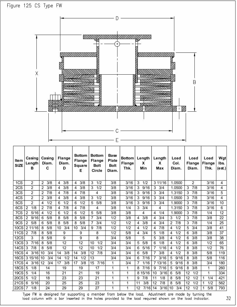
Item SIZE
Casing Length
B
Casing Diam. C
Flange Diam. D
Bottom Flange Square
E
Bottom Flange Bolt Circle
Base Plate Bolt Diam.
Bottom Flange Thk.
Length X Min
Length X
Max
Load Col. Diam.
Load Flange Diam.
Load Flange Thk.
Wgt lbs. (est.)
1CS 2 2 3/8 4 3/8 4 3/8 3 1/2 3/8 3/16 3 1/2 3 11/16 1.0500 2 3/16 4
2CS 2 2 3/8 4 3/8 4 3/8 3 1/2 3/8 3/16 3 9/16 3 3/4 1.0500 3 7/8 3/16 4
3CS 2 2 7/8 4 7/8 4 7/8 4 3/8 3/16 3 9/16 3 3/4 1.3150 3 7/8 3/16 5
4CS 2 2 3/8 4 3/8 4 3/8 3 1/2 3/8 3/16 3 9/16 3 3/4 1.0500 3 7/8 3/16 4
5CS 2 4 1/2 6 1/2 6 1/2 5 5/8 3/8 3/16 3 9/16 3 3/4 1.9000 3 7/8 3/16 10
6CS 2 1/8 2 7/8 4 7/8 4 7/8 4 3/8 1/4 3 3/4 4 1.3150 3 7/8 3/16 6
7CS 2 5/16 4 1/2 6 1/2 6 1/2 5 5/8 3/8 3/8 4 4 1/4 1.9000 3 7/8 1/4 12
8CS 2 9/16 6 5/8 8 5/8 8 5/8 7 3/4 1/2 3/8 4 3/8 4 3/4 3 1/2 3 7/8 3/8 22
9CS 2 5/8 6 5/8 8 5/8 8 5/8 7 3/4 1/2 1/2 4 3/8 4 3/4 2 7/8 3 7/8 1/4 25
10CS 2 11/16 8 5/8 10 3/4 10 3/4 9 7/8 1/2 1/2 4 1/2 4 7/8 4 1/2 5 3/4 3/8 41
11CS 2 7/8 8 5/8 9 9 8 1/2 5/8 4 3/4 5 1/8 4 1/2 6 3/8 3/8 37
12CS 3 8 5/8 9 9 8 3/4 5/8 5 5 3/8 4 1/2 6 3/8 3/8 38
13CS 3 7/16 8 5/8 12 12 10 1/2 3/4 3/4 5 5/8 6 1/8 4 1/2 6 3/8 1/2 65
14CS 3 7/8 8 5/8 12 12 10 1/2 3/4 3/4 6 5/16 7 1/16 4 1/2 8 3/8 1/2 76
15CS 4 3/16 10 3/4 14 3/8 14 3/8 12 7/8 3/4 3/4 6 5/8 7 3/8 4 1/2 8 3/8 5/8 119
16CS 3 15/16 10 3/4 14 1/2 14 1/2 13 3/4 3/4 6 7/16 7 3/16 5 9/16 8 3/8 5/8 116
17CS 4 3/16 12 3/4 17 3/8 17 3/8 15 7/16 1 3/4 7 1/16 7 13/16 5 9/16 8 3/8 3/4 180
18CS 5 1/8 14 19 19 17 1 1 8 7/16 9 7/16 5 9/16 8 3/8 1 260
19CS 5 1/4 16 21 21 19 1 1 8 15/16 10 3/16 6 5/8 12 1/2 1 334
20CS 5 1/2 18 23 23 21 1 1 9 7/8 11 1/8 8 5/8 12 1/2 1 1/4 421
21CS 6 5/16 20 25 25 23 1 1 11 3/8 12 7/8 8 5/8 12 1/2 1 1/2 562
22CS 7 1/8 24 29 29 27 1 1 12 7/16 14 3/16 10 3/4 12 1/2 1 5/8 793
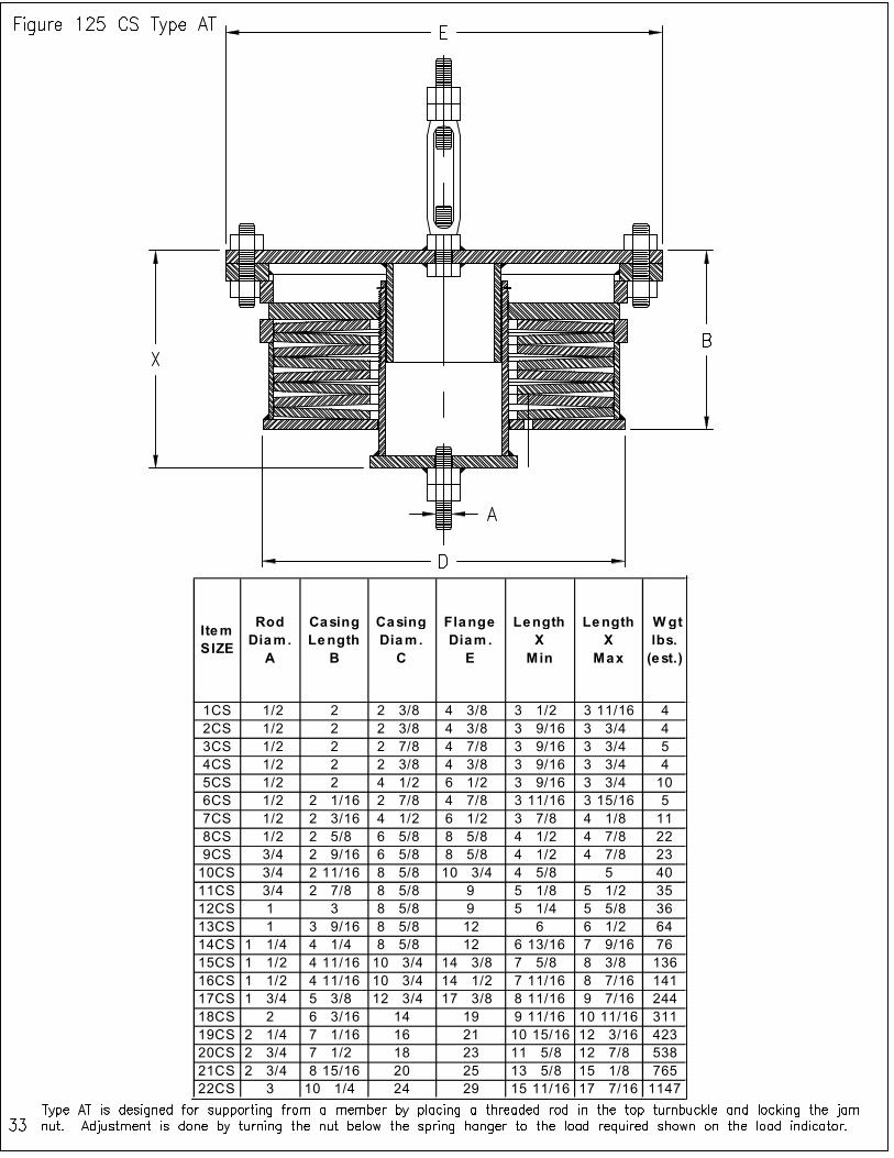
Item SIZE
Rod Diam.
A
Casing Length
B
Casing Diam .
C
Flange Diam .
E
Length X
Min
Length X
Max
W gt lbs.
(est.)
1CS 1/2 2 2 3/8 4 3/8 3 1/2 3 11/16 4
2CS 1/2 2 2 3/8 4 3/8 3 9/16 3 3/4 4
3CS 1/2 2 2 7/8 4 7/8 3 9/16 3 3/4 5
4CS 1/2 2 2 3/8 4 3/8 3 9/16 3 3/4 4
5CS 1/2 2 4 1/2 6 1/2 3 9/16 3 3/4 10
6CS 1/2 2 1/16 2 7/8 4 7/8 3 11/16 3 15/16 5
7CS 1/2 2 3/16 4 1/2 6 1/2 3 7/8 4 1/8 11
8CS 1/2 2 5/8 6 5/8 8 5/8 4 1/2 4 7/8 22
9CS 3/4 2 9/16 6 5/8 8 5/8 4 1/2 4 7/8 23
10CS 3/4 2 11/16 8 5/8 10 3/4 4 5/8 5 40
11CS 3/4 2 7/8 8 5/8 9 5 1/8 5 1/2 35
12CS 1 3 8 5/8 9 5 1/4 5 5/8 36
13CS 1 3 9/16 8 5/8 12 6 6 1/2 64
14CS 1 1/4 4 1/4 8 5/8 12 6 13/16 7 9/16 76
15CS 1 1/2 4 11/16 10 3/4 14 3/8 7 5/8 8 3/8 136
16CS 1 1/2 4 11/16 10 3/4 14 1/2 7 11/16 8 7/16 141
17CS 1 3/4 5 3/8 12 3/4 17 3/8 8 11/16 9 7/16 244
18CS 2 6 3/16 14 19 9 11/16 10 11/16 311
19CS 2 1/4 7 1/16 16 21 10 15/16 12 3/16 423
20CS 2 3/4 7 1/2 18 23 11 5/8 12 7/8 538
21CS 2 3/4 8 15/16 20 25 13 5/8 15 1/8 765
22CS 3 10 1/4 24 29 15 11/16 17 7/16 1147
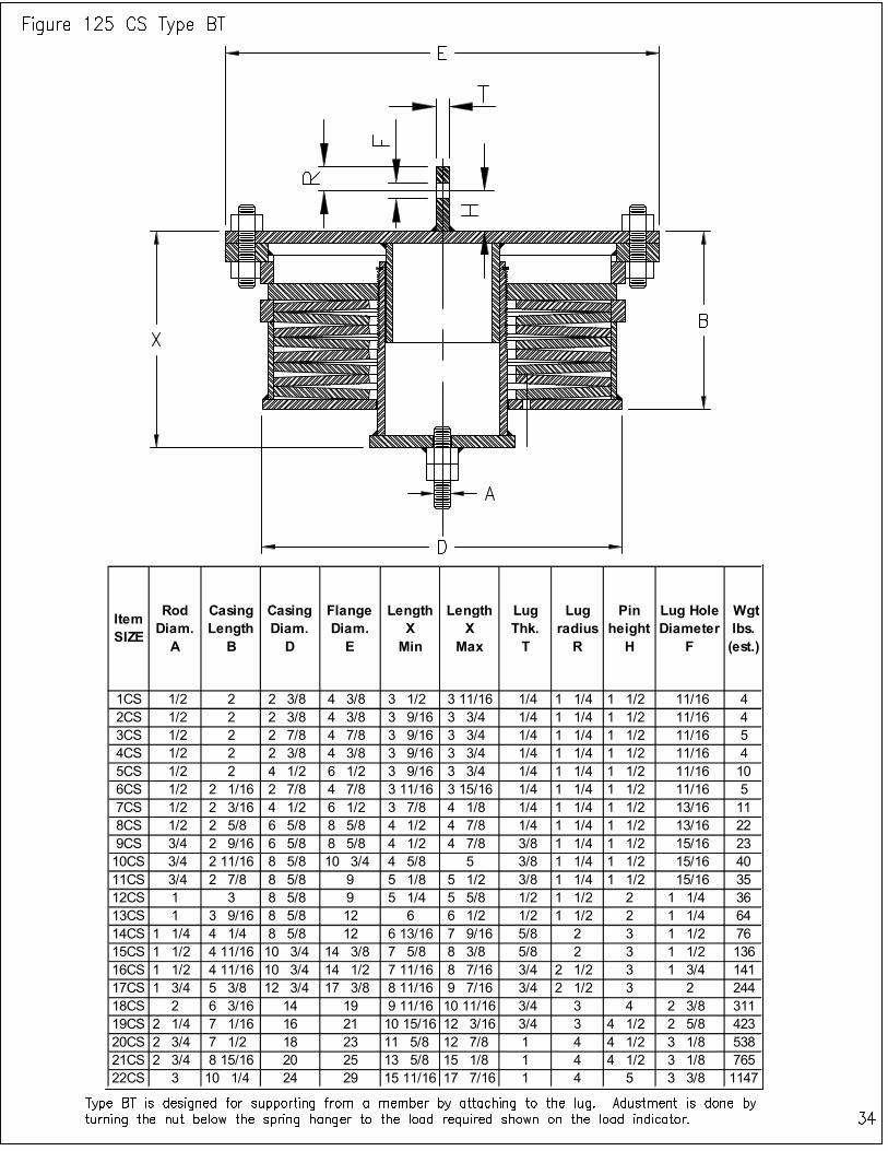
Item SIZE
Rod Diam.
A
Casing Length
B
Casing Diam.
D
Flange Diam.
E
Length X
Min
Length X
Max
Lug Thk. T
Lug radius
R
Pin height
H
Lug Hole Diameter
F
Wgt lbs. (est.)
1CS 1/2 2 2 3/8 4 3/8 3 1/2 3 11/16 1/4 1 1/4 1 1/2 11/16 4
2CS 1/2 2 2 3/8 4 3/8 3 9/16 3 3/4 1/4 1 1/4 1 1/2 11/16 4
3CS 1/2 2 2 7/8 4 7/8 3 9/16 3 3/4 1/4 1 1/4 1 1/2 11/16 5
4CS 1/2 2 2 3/8 4 3/8 3 9/16 3 3/4 1/4 1 1/4 1 1/2 11/16 4
5CS 1/2 2 4 1/2 6 1/2 3 9/16 3 3/4 1/4 1 1/4 1 1/2 11/16 10
6CS 1/2 2 1/16 2 7/8 4 7/8 3 11/16 3 15/16 1/4 1 1/4 1 1/2 11/16 5
7CS 1/2 2 3/16 4 1/2 6 1/2 3 7/8 4 1/8 1/4 1 1/4 1 1/2 13/16 11
8CS 1/2 2 5/8 6 5/8 8 5/8 4 1/2 4 7/8 1/4 1 1/4 1 1/2 13/16 22
9CS 3/4 2 9/16 6 5/8 8 5/8 4 1/2 4 7/8 3/8 1 1/4 1 1/2 15/16 23
10CS 3/4 2 11/16 8 5/8 10 3/4 4 5/8 5 3/8 1 1/4 1 1/2 15/16 40
11CS 3/4 2 7/8 8 5/8 9 5 1/8 5 1/2 3/8 1 1/4 1 1/2 15/16 35
12CS 1 3 8 5/8 9 5 1/4 5 5/8 1/2 1 1/2 2 1 1/4 36
13CS 1 3 9/16 8 5/8 12 6 6 1/2 1/2 1 1/2 2 1 1/4 64
14CS 1 1/4 4 1/4 8 5/8 12 6 13/16 7 9/16 5/8 2 3 1 1/2 76
15CS 1 1/2 4 11/16 10 3/4 14 3/8 7 5/8 8 3/8 5/8 2 3 1 1/2 136
16CS 1 1/2 4 11/16 10 3/4 14 1/2 7 11/16 8 7/16 3/4 2 1/2 3 1 3/4 141
17CS 1 3/4 5 3/8 12 3/4 17 3/8 8 11/16 9 7/16 3/4 2 1/2 3 2 244
18CS 2 6 3/16 14 19 9 11/16 10 11/16 3/4 3 4 2 3/8 311
19CS 2 1/4 7 1/16 16 21 10 15/16 12 3/16 3/4 3 4 1/2 2 5/8 423
20CS 2 3/4 7 1/2 18 23 11 5/8 12 7/8 1 4 4 1/2 3 1/8 538
21CS 2 3/4 8 15/16 20 25 13 5/8 15 1/8 1 4 4 1/2 3 1/8 765
22CS 3 10 1/4 24 29 15 11/16 17 7/16 1 4 5 3 3/8 1147

Item SIZE
Rod Diam. A
Casing Length
B
Casing Diam. C
Flange Diam. D
Length X Min
Length X
Max
Lug Thk. T
clevis opening
S
Lug radius
R
Pin height
H
Lug Hole Diameter
F
Wgt lbs. (est.)
1CS 1/2 2 2 3/8 4 3/8 3 1/2 3 11/16 1/4 7/8 1 1/4 1 1/2 11/16 4
2CS 1/2 2 2 3/8 4 3/8 3 9/16 3 3/4 1/4 7/8 1 1/4 1 1/2 11/16 4
3CS 1/2 2 2 7/8 4 7/8 3 9/16 3 3/4 1/4 7/8 1 1/4 1 1/2 11/16 5
4CS 1/2 2 2 3/8 4 3/8 3 9/16 3 3/4 1/4 7/8 1 1/4 1 1/2 11/16 4
5CS 1/2 2 4 1/2 6 1/2 3 9/16 3 3/4 1/4 7/8 1 1/4 1 1/2 11/16 10
6CS 1/2 2 1/16 2 7/8 4 7/8 3 11/16 3 15/16 1/4 1 1/16 1 1/4 1 1/2 11/16 5
7CS 1/2 2 3/16 4 1/2 6 1/2 3 7/8 4 1/8 1/4 1 1/16 1 1/4 1 1/2 13/16 11
8CS 1/2 2 5/8 6 5/8 8 5/8 4 1/2 4 7/8 1/4 1 1/16 1 1/4 1 1/2 13/16 22
9CS 3/4 2 9/16 6 5/8 8 5/8 4 1/2 4 7/8 3/8 1 1/4 1 1/4 1 1/2 15/16 23
10CS 3/4 2 11/16 8 5/8 10 3/4 4 5/8 5 3/8 1 1/4 1 1/4 1 1/2 15/16 40
11CS 3/4 2 7/8 8 5/8 9 5 1/8 5 1/2 3/8 1 1/4 1 1/4 1 1/2 15/16 35
12CS 1 3 8 5/8 9 5 1/4 5 5/8 1/2 1 5/8 1 1/2 2 1 1/4 36
13CS 1 3 9/16 8 5/8 12 6 6 1/2 1/2 1 5/8 1 1/2 2 1 1/4 64
14CS 1 1/4 4 1/4 8 5/8 12 6 13/16 7 9/16 5/8 2 2 3 1 1/2 76
15CS 1 1/2 4 11/16 10 3/4 14 3/8 7 5/8 8 3/8 5/8 2 2 3 1 1/2 136
16CS 1 1/2 4 11/16 10 3/4 14 1/2 7 11/16 8 7/16 3/4 2 3/8 2 1/2 3 1 3/4 141
17CS 1 3/4 5 3/8 12 3/4 17 3/8 8 11/16 9 7/16 3/4 2 5/8 2 1/2 3 2 244
18CS 2 6 3/16 14 19 9 11/16 10 11/16 3/4 2 7/8 3 4 2 3/8 311
19CS 2 1/4 7 1/16 16 21 10 15/16 12 3/16 3/4 3 1/8 3 4 1/2 2 5/8 423
20CS 2 3/4 7 1/2 18 23 11 5/8 12 7/8 1 3 3/8 4 4 1/2 3 1/8 538
21CS 2 3/4 8 15/16 20 25 13 5/8 15 1/8 1 3 5/8 4 4 1/2 3 1/8 765
22CS 3 10 1/4 24 29 15 11/16 17 7/16 1 3 7/8 4 5 3 3/8 1147
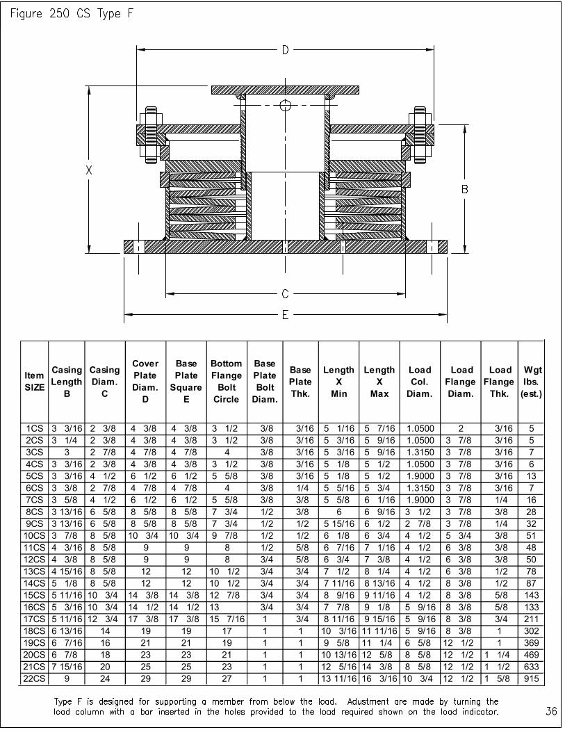
Item SIZE
Casing Length B
Casing Diam. C
Cover Plate Diam. D
Base Plate Square E
Bottom Flange Bolt Circle
Base Plate Bolt Diam.
Base Plate Thk.
Length X Min
Length X Max
Load Col. Diam.
Load Flange Diam.
Load Flange Thk.
Wgt lbs. (est.)
1CS 3 3/16 2 3/8 4 3/8 4 3/8 3 1/2 3/8 3/16 5 1/16 5 7/16 1.0500 2 3/16 5
2CS 3 1/4 2 3/8 4 3/8 4 3/8 3 1/2 3/8 3/16 5 3/16 5 9/16 1.0500 3 7/8 3/16 5
3CS 3 2 7/8 4 7/8 4 7/8 4 3/8 3/16 5 3/16 5 9/16 1.3150 3 7/8 3/16 7
4CS 3 3/16 2 3/8 4 3/8 4 3/8 3 1/2 3/8 3/16 5 1/8 5 1/2 1.0500 3 7/8 3/16 6
5CS 3 3/16 4 1/2 6 1/2 6 1/2 5 5/8 3/8 3/16 5 1/8 5 1/2 1.9000 3 7/8 3/16 13
6CS 3 3/8 2 7/8 4 7/8 4 7/8 4 3/8 1/4 5 5/16 5 3/4 1.3150 3 7/8 3/16 7
7CS 3 5/8 4 1/2 6 1/2 6 1/2 5 5/8 3/8 3/8 5 5/8 6 1/16 1.9000 3 7/8 1/4 16
8CS 3 13/16 6 5/8 8 5/8 8 5/8 7 3/4 1/2 3/8 6 6 9/16 3 1/2 3 7/8 3/8 28
9CS 3 13/16 6 5/8 8 5/8 8 5/8 7 3/4 1/2 1/2 5 15/16 6 1/2 2 7/8 3 7/8 1/4 32
10CS 3 7/8 8 5/8 10 3/4 10 3/4 9 7/8 1/2 1/2 6 1/8 6 3/4 4 1/2 5 3/4 3/8 51
11CS 4 3/16 8 5/8 9 9 8 1/2 5/8 6 7/16 7 1/16 4 1/2 6 3/8 3/8 48
12CS 4 3/8 8 5/8 9 9 8 3/4 5/8 6 3/4 7 3/8 4 1/2 6 3/8 3/8 50
13CS 4 15/16 8 5/8 12 12 10 1/2 3/4 3/4 7 1/2 8 1/4 4 1/2 6 3/8 1/2 78
14CS 5 1/8 8 5/8 12 12 10 1/2 3/4 3/4 7 11/16 8 13/16 4 1/2 8 3/8 1/2 87
15CS 5 11/16 10 3/4 14 3/8 14 3/8 12 7/8 3/4 3/4 8 9/16 9 11/16 4 1/2 8 3/8 5/8 143
16CS 5 3/16 10 3/4 14 1/2 14 1/2 13 3/4 3/4 7 7/8 9 1/8 5 9/16 8 3/8 5/8 133
17CS 5 11/16 12 3/4 17 3/8 17 3/8 15 7/16 1 3/4 8 11/16 9 15/16 5 9/16 8 3/8 3/4 211
18CS 6 13/16 14 19 19 17 1 1 10 3/16 11 11/16 5 9/16 8 3/8 1 302
19CS 6 7/16 16 21 21 19 1 1 9 5/8 11 1/4 6 5/8 12 1/2 1 369
20CS 6 7/8 18 23 23 21 1 1 10 13/16 12 5/8 8 5/8 12 1/2 1 1/4 469
21CS 7 15/16 20 25 25 23 1 1 12 5/16 14 3/8 8 5/8 12 1/2 1 1/2 633
22CS 9 24 29 29 27 1 1 13 11/16 16 3/16 10 3/4 12 1/2 1 5/8 915
Item SIZE
Casing Length
B
Casing Diam. C
Flange Diam. D
Bottom Flange Square
E
Bottom Flange Bolt Circle
Base Plate Bolt Diam.
Bottom Flange Thk.
Length X Min
Length X
Max
Load Col. Diam.
Load Flange Diam.
Load Flange Thk.
Wgt lbs. (est.)
1CS 3 3/16 2 3/8 4 3/8 4 3/8 3 1/2 3/8 3/16 5 1/16 5 1/4 1.0500 2 3/16 5
2CS 3 1/4 2 3/8 4 3/8 4 3/8 3 1/2 3/8 3/16 5 3/16 5 3/8 1.0500 3 7/8 3/16 5
3CS 3 2 7/8 4 7/8 4 7/8 4 3/8 3/16 5 3/16 5 3/8 1.3150 3 7/8 3/16 7
4CS 3 3/16 2 3/8 4 3/8 4 3/8 3 1/2 3/8 3/16 5 1/8 5 5/16 1.0500 3 7/8 3/16 6
5CS 3 3/16 4 1/2 6 1/2 6 1/2 5 5/8 3/8 3/16 5 1/8 5 5/16 1.9000 3 7/8 3/16 13
6CS 3 3/8 2 7/8 4 7/8 4 7/8 4 3/8 1/4 5 5/16 5 9/16 1.3150 3 7/8 3/16 7
7CS 3 5/8 4 1/2 6 1/2 6 1/2 5 5/8 3/8 3/8 5 5/8 5 7/8 1.9000 3 7/8 1/4 16
8CS 3 13/16 6 5/8 8 5/8 8 5/8 7 3/4 1/2 3/8 6 6 3/8 3 1/2 3 7/8 3/8 28
9CS 3 13/16 6 5/8 8 5/8 8 5/8 7 3/4 1/2 1/2 5 15/16 6 5/16 2 7/8 3 7/8 1/4 32
10CS 3 7/8 8 5/8 10 3/4 10 3/4 9 7/8 1/2 1/2 6 1/16 6 7/16 4 1/2 5 3/4 3/8 51
11CS 4 3/16 8 5/8 9 9 8 1/2 5/8 6 3/8 6 3/4 4 1/2 6 3/8 3/8 48
12CS 4 3/8 8 5/8 9 9 8 3/4 5/8 6 3/4 7 1/8 4 1/2 6 3/8 3/8 50
13CS 4 15/16 8 5/8 12 12 10 1/2 3/4 3/4 7 1/2 8 4 1/2 6 3/8 1/2 78
14CS 5 1/8 8 5/8 12 12 10 1/2 3/4 3/4 7 11/16 8 7/16 4 1/2 8 3/8 1/2 86
15CS 5 11/16 10 3/4 14 3/8 14 3/8 12 7/8 3/4 3/4 8 9/16 9 5/16 4 1/2 8 3/8 5/8 143
16CS 5 3/16 10 3/4 14 1/2 14 1/2 13 3/4 3/4 7 3/4 8 1/2 5 9/16 8 3/8 5/8 133
17CS 5 11/16 12 3/4 17 3/8 17 3/8 15 7/16 1 3/4 8 11/16 9 7/16 5 9/16 8 3/8 3/4 210
18CS 6 13/16 14 19 19 17 1 1 10 3/16 11 3/16 5 9/16 8 3/8 1 301
19CS 6 7/16 16 21 21 19 1 1 9 5/8 10 7/8 6 5/8 12 1/2 1 368
20CS 6 7/8 18 23 23 21 1 1 10 13/16 12 1/16 8 5/8 12 1/2 1 1/4 468
21CS 7 15/16 20 25 25 23 1 1 12 5/16 13 13/16 8 5/8 12 1/2 1 1/2 631
22CS 9 24 29 29 27 1 1 13 11/16 15 7/16 10 3/4 12 1/2 1 5/8 912
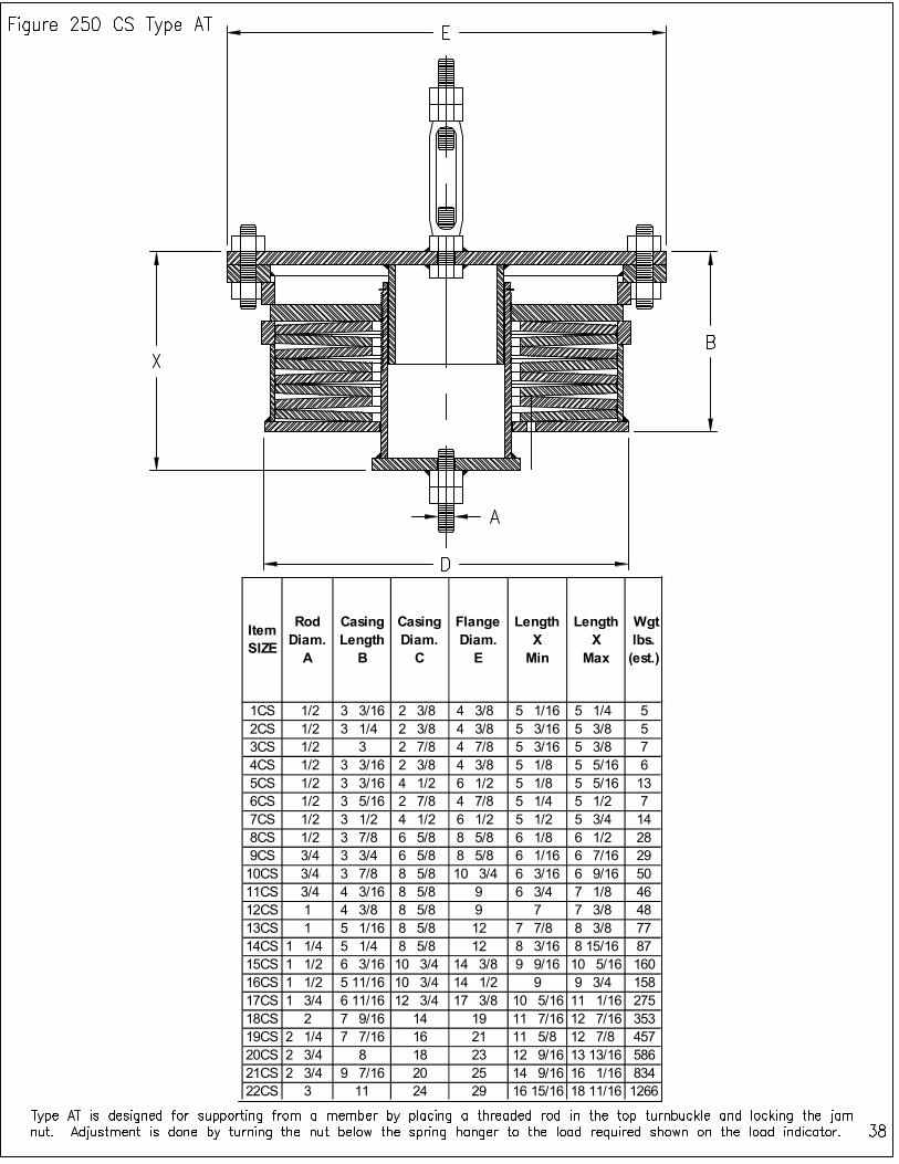
Item SIZE
Rod Diam.
A
Casing Length
B
Casing Diam.
C
Flange Diam.
E
Length X
Min
Length X
Max
Wgt lbs. (est.)
1CS 1/2 3 3/16 2 3/8 4 3/8 5 1/16 5 1/4 5
2CS 1/2 3 1/4 2 3/8 4 3/8 5 3/16 5 3/8 5
3CS 1/2 3 2 7/8 4 7/8 5 3/16 5 3/8 7
4CS 1/2 3 3/16 2 3/8 4 3/8 5 1/8 5 5/16 6
5CS 1/2 3 3/16 4 1/2 6 1/2 5 1/8 5 5/16 13
6CS 1/2 3 5/16 2 7/8 4 7/8 5 1/4 5 1/2 7
7CS 1/2 3 1/2 4 1/2 6 1/2 5 1/2 5 3/4 14
8CS 1/2 3 7/8 6 5/8 8 5/8 6 1/8 6 1/2 28
9CS 3/4 3 3/4 6 5/8 8 5/8 6 1/16 6 7/16 29
10CS 3/4 3 7/8 8 5/8 10 3/4 6 3/16 6 9/16 50
11CS 3/4 4 3/16 8 5/8 9 6 3/4 7 1/8 46
12CS 1 4 3/8 8 5/8 9 7 7 3/8 48
13CS 1 5 1/16 8 5/8 12 7 7/8 8 3/8 77
14CS 1 1/4 5 1/4 8 5/8 12 8 3/16 8 15/16 87
15CS 1 1/2 6 3/16 10 3/4 14 3/8 9 9/16 10 5/16 160
16CS 1 1/2 5 11/16 10 3/4 14 1/2 9 9 3/4 158
17CS 1 3/4 6 11/16 12 3/4 17 3/8 10 5/16 11 1/16 275
18CS 2 7 9/16 14 19 11 7/16 12 7/16 353
19CS 2 1/4 7 7/16 16 21 11 5/8 12 7/8 457
20CS 2 3/4 8 18 23 12 9/16 13 13/16 586
21CS 2 3/4 9 7/16 20 25 14 9/16 16 1/16 834
22CS 3 11 24 29 16 15/16 18 11/16 1266
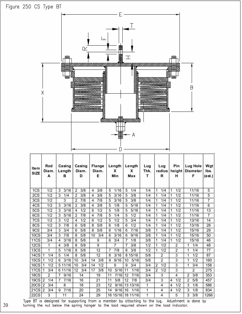
Item SIZE
Rod Diam.
A
Casing Length
B
Casing Diam.
D
Flange Diam.
E
Length X
Min
Length X
Max
Lug Thk. T
Lug radius
R
Pin height
H
Lug Hole Diameter
F
Wgt lbs. (est.)
1CS 1/2 3 3/16 2 3/8 4 3/8 5 1/16 5 1/4 1/4 1 1/4 1 1/2 11/16 5
2CS 1/2 3 1/4 2 3/8 4 3/8 5 3/16 5 3/8 1/4 1 1/4 1 1/2 11/16 5
3CS 1/2 3 2 7/8 4 7/8 5 3/16 5 3/8 1/4 1 1/4 1 1/2 11/16 7
4CS 1/2 3 3/16 2 3/8 4 3/8 5 1/8 5 5/16 1/4 1 1/4 1 1/2 11/16 6
5CS 1/2 3 3/16 4 1/2 6 1/2 5 1/8 5 5/16 1/4 1 1/4 1 1/2 11/16 13
6CS 1/2 3 5/16 2 7/8 4 7/8 5 1/4 5 1/2 1/4 1 1/4 1 1/2 11/16 7
7CS 1/2 3 1/2 4 1/2 6 1/2 5 1/2 5 3/4 1/4 1 1/4 1 1/2 13/16 14
8CS 1/2 3 7/8 6 5/8 8 5/8 6 1/8 6 1/2 1/4 1 1/4 1 1/2 13/16 28
9CS 3/4 3 3/4 6 5/8 8 5/8 6 1/16 6 7/16 3/8 1 1/4 1 1/2 15/16 29
10CS 3/4 3 7/8 8 5/8 10 3/4 6 3/16 6 9/16 3/8 1 1/4 1 1/2 15/16 50
11CS 3/4 4 3/16 8 5/8 9 6 3/4 7 1/8 3/8 1 1/4 1 1/2 15/16 46
12CS 1 4 3/8 8 5/8 9 7 7 3/8 1/2 1 1/2 2 1 1/4 48
13CS 1 5 1/16 8 5/8 12 7 7/8 8 3/8 1/2 1 1/2 2 1 1/4 77
14CS 1 1/4 5 1/4 8 5/8 12 8 3/16 8 15/16 5/8 2 3 1 1/2 87
15CS 1 1/2 6 3/16 10 3/4 14 3/8 9 9/16 10 5/16 5/8 2 3 1 1/2 160
16CS 1 1/2 5 11/16 10 3/4 14 1/2 9 9 3/4 3/4 2 1/2 3 1 3/4 158
17CS 1 3/4 6 11/16 12 3/4 17 3/8 10 5/16 11 1/16 3/4 2 1/2 3 2 275
18CS 2 7 9/16 14 19 11 7/16 12 7/16 3/4 3 4 2 3/8 353
19CS 2 1/4 7 7/16 16 21 11 5/8 12 7/8 3/4 3 4 1/2 2 5/8 457
20CS 2 3/4 8 18 23 12 9/16 13 13/16 1 4 4 1/2 3 1/8 586
21CS 2 3/4 9 7/16 20 25 14 9/16 16 1/16 1 4 4 1/2 3 1/8 834
22CS 3 11 24 29 16 15/16 18 11/16 1 4 5 3 3/8 1266
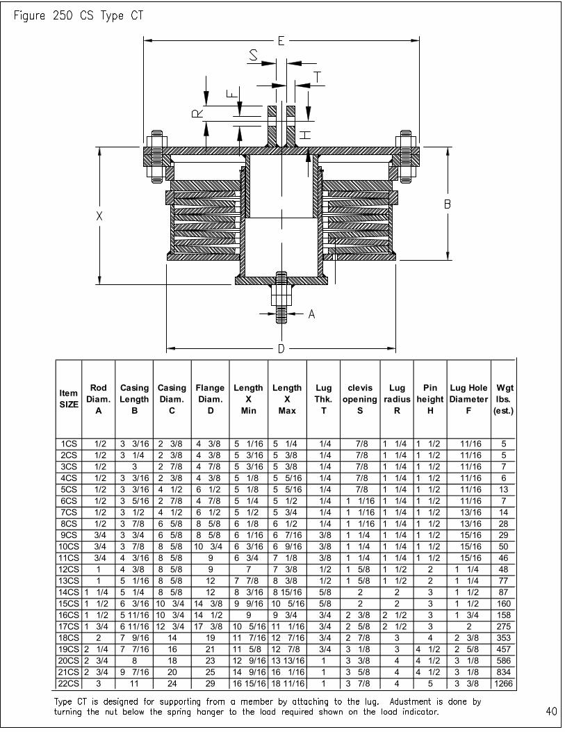
Item SIZE
Rod Diam. A
Casing Length
B
Casing Diam. C
Flange Diam. D
Length X Min
Length X
Max
Lug Thk. T
clevis opening
S
Lug radius
R
Pin height
H
Lug Hole Diameter
F
Wgt lbs. (est.)
1CS 1/2 3 3/16 2 3/8 4 3/8 5 1/16 5 1/4 1/4 7/8 1 1/4 1 1/2 11/16 5
2CS 1/2 3 1/4 2 3/8 4 3/8 5 3/16 5 3/8 1/4 7/8 1 1/4 1 1/2 11/16 5
3CS 1/2 3 2 7/8 4 7/8 5 3/16 5 3/8 1/4 7/8 1 1/4 1 1/2 11/16 7
4CS 1/2 3 3/16 2 3/8 4 3/8 5 1/8 5 5/16 1/4 7/8 1 1/4 1 1/2 11/16 6
5CS 1/2 3 3/16 4 1/2 6 1/2 5 1/8 5 5/16 1/4 7/8 1 1/4 1 1/2 11/16 13
6CS 1/2 3 5/16 2 7/8 4 7/8 5 1/4 5 1/2 1/4 1 1/16 1 1/4 1 1/2 11/16 7
7CS 1/2 3 1/2 4 1/2 6 1/2 5 1/2 5 3/4 1/4 1 1/16 1 1/4 1 1/2 13/16 14
8CS 1/2 3 7/8 6 5/8 8 5/8 6 1/8 6 1/2 1/4 1 1/16 1 1/4 1 1/2 13/16 28
9CS 3/4 3 3/4 6 5/8 8 5/8 6 1/16 6 7/16 3/8 1 1/4 1 1/4 1 1/2 15/16 29
10CS 3/4 3 7/8 8 5/8 10 3/4 6 3/16 6 9/16 3/8 1 1/4 1 1/4 1 1/2 15/16 50
11CS 3/4 4 3/16 8 5/8 9 6 3/4 7 1/8 3/8 1 1/4 1 1/4 1 1/2 15/16 46
12CS 1 4 3/8 8 5/8 9 7 7 3/8 1/2 1 5/8 1 1/2 2 1 1/4 48
13CS 1 5 1/16 8 5/8 12 7 7/8 8 3/8 1/2 1 5/8 1 1/2 2 1 1/4 77
14CS 1 1/4 5 1/4 8 5/8 12 8 3/16 8 15/16 5/8 2 2 3 1 1/2 87
15CS 1 1/2 6 3/16 10 3/4 14 3/8 9 9/16 10 5/16 5/8 2 2 3 1 1/2 160
16CS 1 1/2 5 11/16 10 3/4 14 1/2 9 9 3/4 3/4 2 3/8 2 1/2 3 1 3/4 158
17CS 1 3/4 6 11/16 12 3/4 17 3/8 10 5/16 11 1/16 3/4 2 5/8 2 1/2 3 2 275
18CS 2 7 9/16 14 19 11 7/16 12 7/16 3/4 2 7/8 3 4 2 3/8 353
19CS 2 1/4 7 7/16 16 21 11 5/8 12 7/8 3/4 3 1/8 3 4 1/2 2 5/8 457
20CS 2 3/4 8 18 23 12 9/16 13 13/16 1 3 3/8 4 4 1/2 3 1/8 586
21CS 2 3/4 9 7/16 20 25 14 9/16 16 1/16 1 3 5/8 4 4 1/2 3 1/8 834
22CS 3 11 24 29 16 15/16 18 11/16 1 3 7/8 4 5 3 3/8 1266
Item SIZE
Casing Length B
Casing Diam. C
Cover Plate Diam. D
Base Plate Square E
Bottom Flange Bolt Circle
Base Plate Bolt Diam.
Base Plate Thk.
Length X Min
Length X Max
Load Col. Diam.
Load Flange Diam.
Load Flange Thk.
Wgt lbs. (est.)
1CS 4 7/16 2 3/8 4 3/8 4 3/8 3 1/2 3/8 3/16 6 5/8 7 1.0500 2 3/16 6
2CS 4 1/2 2 3/8 4 3/8 4 3/8 3 1/2 3/8 3/16 6 3/4 7 1/8 1.0500 3 7/8 3/16 6
3CS 5 2 7/8 4 7/8 4 7/8 4 3/8 3/16 6 3/4 7 1/8 1.3150 3 7/8 3/16 8
4CS 4 7/16 2 3/8 4 3/8 4 3/8 3 1/2 3/8 3/16 6 11/16 7 1/16 1.0500 3 7/8 3/16 7
5CS 4 7/16 4 1/2 6 1/2 6 1/2 5 5/8 3/8 3/16 6 3/4 7 1/8 1.9000 3 7/8 3/16 16
6CS 4 9/16 2 7/8 4 7/8 4 7/8 4 3/8 1/4 6 13/16 7 1/4 1.3150 3 7/8 3/16 9
7CS 4 7/8 4 1/2 6 1/2 6 1/2 5 5/8 3/8 3/8 7 1/4 7 11/16 1.9000 3 7/8 1/4 19
8CS 5 1/16 6 5/8 8 5/8 8 5/8 7 3/4 1/2 3/8 7 9/16 8 1/8 3 1/2 3 7/8 3/8 34
9CS 5 6 5/8 8 5/8 8 5/8 7 3/4 1/2 1/2 7 7/16 8 2 7/8 3 7/8 1/4 38
10CS 5 1/16 8 5/8 10 3/4 10 3/4 9 7/8 1/2 1/2 7 5/8 8 1/4 4 1/2 5 3/4 3/8 61
11CS 5 7/16 8 5/8 9 9 8 1/2 5/8 8 1/16 8 11/16 4 1/2 6 3/8 3/8 58
12CS 5 11/16 8 5/8 9 9 8 3/4 5/8 8 1/2 9 1/8 4 1/2 6 3/8 3/8 62
13CS 6 3/8 8 5/8 12 12 10 1/2 3/4 3/4 9 3/8 10 1/8 4 1/2 6 3/8 1/2 90
14CS 6 3/8 8 5/8 12 12 10 1/2 3/4 3/4 9 5/16 10 7/16 4 1/2 8 3/8 1/2 97
15CS 7 1/4 10 3/4 14 3/8 14 3/8 12 7/8 3/4 3/4 10 1/2 11 5/8 4 1/2 8 3/8 5/8 166
16CS 6 3/8 10 3/4 14 1/2 14 1/2 13 3/4 3/4 9 7/16 10 11/16 5 9/16 8 3/8 5/8 150
17CS 7 1/8 12 3/4 17 3/8 17 3/8 15 7/16 1 3/4 10 9/16 11 13/16 5 9/16 8 3/8 3/4 242
18CS 8 7/16 14 19 19 17 1 1 12 5/16 13 13/16 5 9/16 8 3/8 1 345
19CS 7 11/16 16 21 21 19 1 1 11 1/4 13 6 5/8 12 1/2 1 407
20CS 8 1/4 18 23 23 21 1 1 12 9/16 14 7/16 8 5/8 12 1/2 1 1/4 522
21CS 9 1/2 20 25 25 23 1 1 14 5/16 16 9/16 8 5/8 12 1/2 1 1/2 709
22CS 10 7/8 24 29 29 27 1 1 16 1/8 18 5/8 10 3/4 12 1/2 1 5/8 1044
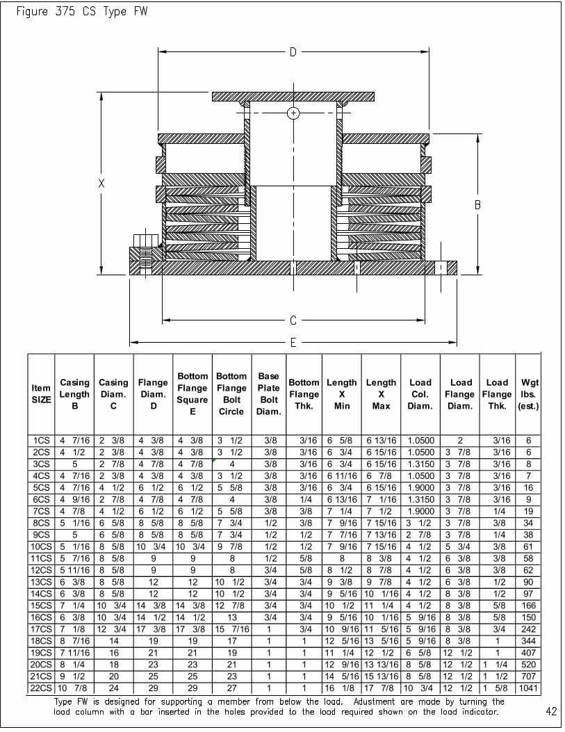
Item SIZE
Casing Length
B
Casing Diam. C
Flange Diam. D
Bottom Flange Square
E
Bottom Flange Bolt Circle
Base Plate Bolt Diam.
Bottom Flange Thk.
Length X Min
Length X
Max
Load Col. Diam.
Load Flange Diam.
Load Flange Thk.
Wgt lbs. (est.)
1CS 4 7/16 2 3/8 4 3/8 4 3/8 3 1/2 3/8 3/16 6 5/8 6 13/16 1.0500 2 3/16 6
2CS 4 1/2 2 3/8 4 3/8 4 3/8 3 1/2 3/8 3/16 6 3/4 6 15/16 1.0500 3 7/8 3/16 6
3CS 5 2 7/8 4 7/8 4 7/8 4 3/8 3/16 6 3/4 6 15/16 1.3150 3 7/8 3/16 8
4CS 4 7/16 2 3/8 4 3/8 4 3/8 3 1/2 3/8 3/16 6 11/16 6 7/8 1.0500 3 7/8 3/16 7
5CS 4 7/16 4 1/2 6 1/2 6 1/2 5 5/8 3/8 3/16 6 3/4 6 15/16 1.9000 3 7/8 3/16 16
6CS 4 9/16 2 7/8 4 7/8 4 7/8 4 3/8 1/4 6 13/16 7 1/16 1.3150 3 7/8 3/16 9
7CS 4 7/8 4 1/2 6 1/2 6 1/2 5 5/8 3/8 3/8 7 1/4 7 1/2 1.9000 3 7/8 1/4 19
8CS 5 1/16 6 5/8 8 5/8 8 5/8 7 3/4 1/2 3/8 7 9/16 7 15/16 3 1/2 3 7/8 3/8 34
9CS 5 6 5/8 8 5/8 8 5/8 7 3/4 1/2 1/2 7 7/16 7 13/16 2 7/8 3 7/8 1/4 38
10CS 5 1/16 8 5/8 10 3/4 10 3/4 9 7/8 1/2 1/2 7 9/16 7 15/16 4 1/2 5 3/4 3/8 61
11CS 5 7/16 8 5/8 9 9 8 1/2 5/8 8 8 3/8 4 1/2 6 3/8 3/8 58
12CS 5 11/16 8 5/8 9 9 8 3/4 5/8 8 1/2 8 7/8 4 1/2 6 3/8 3/8 62
13CS 6 3/8 8 5/8 12 12 10 1/2 3/4 3/4 9 3/8 9 7/8 4 1/2 6 3/8 1/2 90
14CS 6 3/8 8 5/8 12 12 10 1/2 3/4 3/4 9 5/16 10 1/16 4 1/2 8 3/8 1/2 97
15CS 7 1/4 10 3/4 14 3/8 14 3/8 12 7/8 3/4 3/4 10 1/2 11 1/4 4 1/2 8 3/8 5/8 166
16CS 6 3/8 10 3/4 14 1/2 14 1/2 13 3/4 3/4 9 5/16 10 1/16 5 9/16 8 3/8 5/8 150
17CS 7 1/8 12 3/4 17 3/8 17 3/8 15 7/16 1 3/4 10 9/16 11 5/16 5 9/16 8 3/8 3/4 242
18CS 8 7/16 14 19 19 17 1 1 12 5/16 13 5/16 5 9/16 8 3/8 1 344
19CS 7 11/16 16 21 21 19 1 1 11 1/4 12 1/2 6 5/8 12 1/2 1 407
20CS 8 1/4 18 23 23 21 1 1 12 9/16 13 13/16 8 5/8 12 1/2 1 1/4 520
21CS 9 1/2 20 25 25 23 1 1 14 5/16 15 13/16 8 5/8 12 1/2 1 1/2 707
22CS 10 7/8 24 29 29 27 1 1 16 1/8 17 7/8 10 3/4 12 1/2 1 5/8 1041
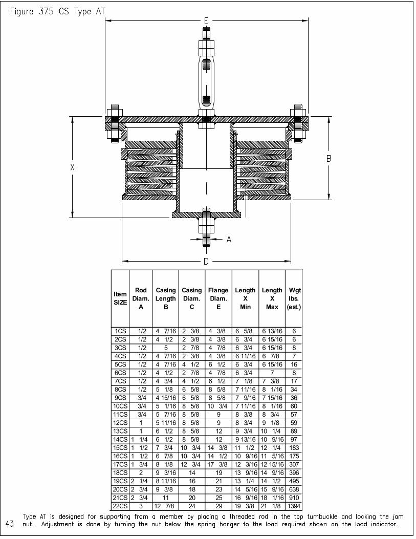
Item SIZE
Rod Diam.
A
Casing Length
B
Casing Diam.
C
Flange Diam.
E
Length X
Min
Length X
Max
Wgt lbs. (est.)
1CS 1/2 4 7/16 2 3/8 4 3/8 6 5/8 6 13/16 6
2CS 1/2 4 1/2 2 3/8 4 3/8 6 3/4 6 15/16 6
3CS 1/2 5 2 7/8 4 7/8 6 3/4 6 15/16 8
4CS 1/2 4 7/16 2 3/8 4 3/8 6 11/16 6 7/8 7
5CS 1/2 4 7/16 4 1/2 6 1/2 6 3/4 6 15/16 16
6CS 1/2 4 1/2 2 7/8 4 7/8 6 3/4 7 8
7CS 1/2 4 3/4 4 1/2 6 1/2 7 1/8 7 3/8 17
8CS 1/2 5 1/8 6 5/8 8 5/8 7 11/16 8 1/16 34
9CS 3/4 4 15/16 6 5/8 8 5/8 7 9/16 7 15/16 36
10CS 3/4 5 1/16 8 5/8 10 3/4 7 11/16 8 1/16 60
11CS 3/4 5 7/16 8 5/8 9 8 3/8 8 3/4 57
12CS 1 5 11/16 8 5/8 9 8 3/4 9 1/8 59
13CS 1 6 1/2 8 5/8 12 9 3/4 10 1/4 89
14CS 1 1/4 6 1/2 8 5/8 12 9 13/16 10 9/16 97
15CS 1 1/2 7 3/4 10 3/4 14 3/8 11 1/2 12 1/4 183
16CS 1 1/2 6 7/8 10 3/4 14 1/2 10 9/16 11 5/16 175
17CS 1 3/4 8 1/8 12 3/4 17 3/8 12 3/16 12 15/16 307
18CS 2 9 3/16 14 19 13 9/16 14 9/16 396
19CS 2 1/4 8 11/16 16 21 13 1/4 14 1/2 495
20CS 2 3/4 9 3/8 18 23 14 5/16 15 9/16 638
21CS 2 3/4 11 20 25 16 9/16 18 1/16 910
22CS 3 12 7/8 24 29 19 3/8 21 1/8 1394

Item SIZE
Rod Diam.
A
Casing Length
B
Casing Diam.
D
Flange Diam.
E
Length X
Min
Length X
Max
Lug Thk. T
Lug radius
R
Pin height
H
Lug Hole Diameter
F
Wgt lbs. (est.)
1CS 1/2 4 7/16 2 3/8 4 3/8 6 5/8 6 13/16 1/4 1 1/4 1 1/2 11/16 6
2CS 1/2 4 1/2 2 3/8 4 3/8 6 3/4 6 15/16 1/4 1 1/4 1 1/2 11/16 6
3CS 1/2 5 2 7/8 4 7/8 6 3/4 6 15/16 1/4 1 1/4 1 1/2 11/16 8
4CS 1/2 4 7/16 2 3/8 4 3/8 6 11/16 6 7/8 1/4 1 1/4 1 1/2 11/16 7
5CS 1/2 4 7/16 4 1/2 6 1/2 6 3/4 6 15/16 1/4 1 1/4 1 1/2 11/16 16
6CS 1/2 4 1/2 2 7/8 4 7/8 6 3/4 7 1/4 1 1/4 1 1/2 11/16 8
7CS 1/2 4 3/4 4 1/2 6 1/2 7 1/8 7 3/8 1/4 1 1/4 1 1/2 13/16 17
8CS 1/2 5 1/8 6 5/8 8 5/8 7 11/16 8 1/16 1/4 1 1/4 1 1/2 13/16 34
9CS 3/4 4 15/16 6 5/8 8 5/8 7 9/16 7 15/16 3/8 1 1/4 1 1/2 15/16 36
10CS 3/4 5 1/16 8 5/8 10 3/4 7 11/16 8 1/16 3/8 1 1/4 1 1/2 15/16 60
11CS 3/4 5 7/16 8 5/8 9 8 3/8 8 3/4 3/8 1 1/4 1 1/2 15/16 57
12CS 1 5 11/16 8 5/8 9 8 3/4 9 1/8 1/2 1 1/2 2 1 1/4 59
13CS 1 6 1/2 8 5/8 12 9 3/4 10 1/4 1/2 1 1/2 2 1 1/4 89
14CS 1 1/4 6 1/2 8 5/8 12 9 13/16 10 9/16 5/8 2 3 1 1/2 97
15CS 1 1/2 7 3/4 10 3/4 14 3/8 11 1/2 12 1/4 5/8 2 3 1 1/2 183
16CS 1 1/2 6 7/8 10 3/4 14 1/2 10 9/16 11 5/16 3/4 2 1/2 3 1 3/4 175
17CS 1 3/4 8 1/8 12 3/4 17 3/8 12 3/16 12 15/16 3/4 2 1/2 3 2 307
18CS 2 9 3/16 14 19 13 9/16 14 9/16 3/4 3 4 2 3/8 396
19CS 2 1/4 8 11/16 16 21 13 1/4 14 1/2 3/4 3 4 1/2 2 5/8 495
20CS 2 3/4 9 3/8 18 23 14 5/16 15 9/16 1 4 4 1/2 3 1/8 638
21CS 2 3/4 11 20 25 16 9/16 18 1/16 1 4 4 1/2 3 1/8 910
22CS 3 12 7/8 24 29 19 3/8 21 1/8 1 4 5 3 3/8 1394
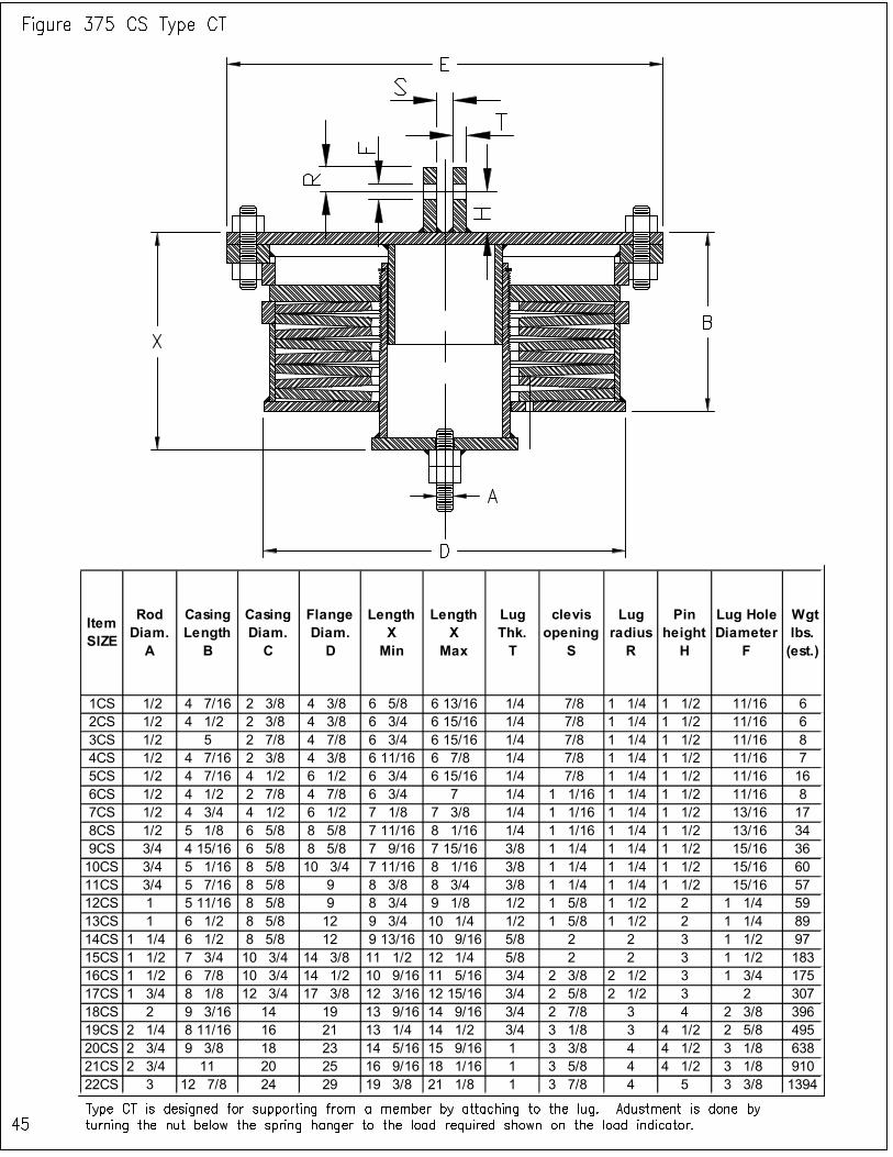
Item SIZE
Rod Diam. A
Casing Length
B
Casing Diam. C
Flange Diam. D
Length X Min
Length X
Max
Lug Thk. T
clevis opening
S
Lug radius
R
Pin height
H
Lug Hole Diameter
F
Wgt lbs. (est.)
1CS 1/2 4 7/16 2 3/8 4 3/8 6 5/8 6 13/16 1/4 7/8 1 1/4 1 1/2 11/16 6
2CS 1/2 4 1/2 2 3/8 4 3/8 6 3/4 6 15/16 1/4 7/8 1 1/4 1 1/2 11/16 6
3CS 1/2 5 2 7/8 4 7/8 6 3/4 6 15/16 1/4 7/8 1 1/4 1 1/2 11/16 8
4CS 1/2 4 7/16 2 3/8 4 3/8 6 11/16 6 7/8 1/4 7/8 1 1/4 1 1/2 11/16 7
5CS 1/2 4 7/16 4 1/2 6 1/2 6 3/4 6 15/16 1/4 7/8 1 1/4 1 1/2 11/16 16
6CS 1/2 4 1/2 2 7/8 4 7/8 6 3/4 7 1/4 1 1/16 1 1/4 1 1/2 11/16 8
7CS 1/2 4 3/4 4 1/2 6 1/2 7 1/8 7 3/8 1/4 1 1/16 1 1/4 1 1/2 13/16 17
8CS 1/2 5 1/8 6 5/8 8 5/8 7 11/16 8 1/16 1/4 1 1/16 1 1/4 1 1/2 13/16 34
9CS 3/4 4 15/16 6 5/8 8 5/8 7 9/16 7 15/16 3/8 1 1/4 1 1/4 1 1/2 15/16 36
10CS 3/4 5 1/16 8 5/8 10 3/4 7 11/16 8 1/16 3/8 1 1/4 1 1/4 1 1/2 15/16 60
11CS 3/4 5 7/16 8 5/8 9 8 3/8 8 3/4 3/8 1 1/4 1 1/4 1 1/2 15/16 57
12CS 1 5 11/16 8 5/8 9 8 3/4 9 1/8 1/2 1 5/8 1 1/2 2 1 1/4 59
13CS 1 6 1/2 8 5/8 12 9 3/4 10 1/4 1/2 1 5/8 1 1/2 2 1 1/4 89
14CS 1 1/4 6 1/2 8 5/8 12 9 13/16 10 9/16 5/8 2 2 3 1 1/2 97
15CS 1 1/2 7 3/4 10 3/4 14 3/8 11 1/2 12 1/4 5/8 2 2 3 1 1/2 183
16CS 1 1/2 6 7/8 10 3/4 14 1/2 10 9/16 11 5/16 3/4 2 3/8 2 1/2 3 1 3/4 175
17CS 1 3/4 8 1/8 12 3/4 17 3/8 12 3/16 12 15/16 3/4 2 5/8 2 1/2 3 2 307
18CS 2 9 3/16 14 19 13 9/16 14 9/16 3/4 2 7/8 3 4 2 3/8 396
19CS 2 1/4 8 11/16 16 21 13 1/4 14 1/2 3/4 3 1/8 3 4 1/2 2 5/8 495
20CS 2 3/4 9 3/8 18 23 14 5/16 15 9/16 1 3 3/8 4 4 1/2 3 1/8 638
21CS 2 3/4 11 20 25 16 9/16 18 1/16 1 3 5/8 4 4 1/2 3 1/8 910
22CS 3 12 7/8 24 29 19 3/8 21 1/8 1 3 7/8 4 5 3 3/8 1394
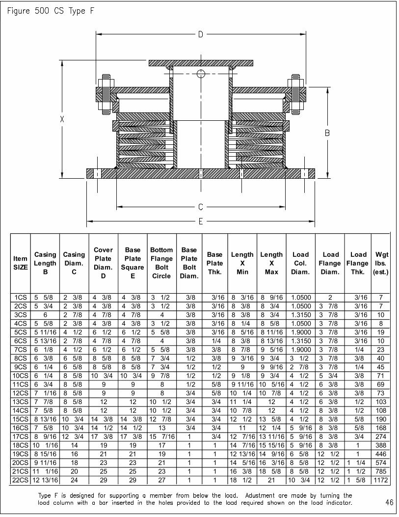
Item SIZE
Casing Length B
Casing Diam. C
Cover Plate Diam. D
Base Plate Square E
Bottom Flange Bolt Circle
Base Plate Bolt Diam.
Base Plate Thk.
Length X Min
Length X Max
Load Col. Diam.
Load Flange Diam.
Load Flange Thk.
Wgt lbs. (est.)
1CS 5 5/8 2 3/8 4 3/8 4 3/8 3 1/2 3/8 3/16 8 3/16 8 9/16 1.0500 2 3/16 7
2CS 5 3/4 2 3/8 4 3/8 4 3/8 3 1/2 3/8 3/16 8 3/8 8 3/4 1.0500 3 7/8 3/16 7
3CS 6 2 7/8 4 7/8 4 7/8 4 3/8 3/16 8 3/8 8 3/4 1.3150 3 7/8 3/16 10
4CS 5 5/8 2 3/8 4 3/8 4 3/8 3 1/2 3/8 3/16 8 1/4 8 5/8 1.0500 3 7/8 3/16 8
5CS 5 11/16 4 1/2 6 1/2 6 1/2 5 5/8 3/8 3/16 8 5/16 8 11/16 1.9000 3 7/8 3/16 19
6CS 5 13/16 2 7/8 4 7/8 4 7/8 4 3/8 1/4 8 3/8 8 13/16 1.3150 3 7/8 3/16 10
7CS 6 1/8 4 1/2 6 1/2 6 1/2 5 5/8 3/8 3/8 8 7/8 9 5/16 1.9000 3 7/8 1/4 23
8CS 6 3/8 6 5/8 8 5/8 8 5/8 7 3/4 1/2 3/8 9 3/16 9 3/4 3 1/2 3 7/8 3/8 40
9CS 6 1/4 6 5/8 8 5/8 8 5/8 7 3/4 1/2 1/2 9 9 9/16 2 7/8 3 7/8 1/4 45
10CS 6 1/4 8 5/8 10 3/4 10 3/4 9 7/8 1/2 1/2 9 1/8 9 3/4 4 1/2 5 3/4 3/8 71
11CS 6 3/4 8 5/8 9 9 8 1/2 5/8 9 11/16 10 5/16 4 1/2 6 3/8 3/8 69
12CS 7 1/16 8 5/8 9 9 8 3/4 5/8 10 1/4 10 7/8 4 1/2 6 3/8 3/8 73
13CS 7 7/8 8 5/8 12 12 10 1/2 3/4 3/4 11 1/4 12 4 1/2 6 3/8 1/2 103
14CS 7 5/8 8 5/8 12 12 10 1/2 3/4 3/4 10 7/8 12 4 1/2 8 3/8 1/2 108
15CS 8 13/16 10 3/4 14 3/8 14 3/8 12 7/8 3/4 3/4 12 1/2 13 5/8 4 1/2 8 3/8 5/8 190
16CS 7 5/8 10 3/4 14 1/2 14 1/2 13 3/4 3/4 11 12 1/4 5 9/16 8 3/8 5/8 168
17CS 8 9/16 12 3/4 17 3/8 17 3/8 15 7/16 1 3/4 12 7/16 13 11/16 5 9/16 8 3/8 3/4 274
18CS 10 1/16 14 19 19 17 1 1 14 7/16 15 15/16 5 9/16 8 3/8 1 388
19CS 8 15/16 16 21 21 19 1 1 12 13/16 14 9/16 6 5/8 12 1/2 1 446
20CS 9 11/16 18 23 23 21 1 1 14 5/16 16 3/16 8 5/8 12 1/2 1 1/4 574
21CS 11 1/16 20 25 25 23 1 1 16 3/8 18 5/8 8 5/8 12 1/2 1 1/2 785
22CS 12 13/16 24 29 29 27 1 1 18 1/2 21 10 3/4 12 1/2 1 5/8 1172
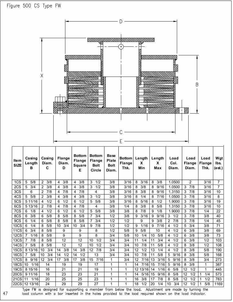
Item SIZE
Casing Length
B
Casing Diam. C
Flange Diam. D
Bottom Flange Square
E
Bottom Flange Bolt Circle
Base Plate Bolt Diam.
Bottom Flange Thk.
Length X Min
Length X
Max
Load Col. Diam.
Load Flange Diam.
Load Flange Thk.
Wgt lbs. (est.)
1CS 5 5/8 2 3/8 4 3/8 4 3/8 3 1/2 3/8 3/16 8 3/16 8 3/8 1.0500 2 3/16 7
2CS 5 3/4 2 3/8 4 3/8 4 3/8 3 1/2 3/8 3/16 8 3/8 8 9/16 1.0500 3 7/8 3/16 7
3CS 6 2 7/8 4 7/8 4 7/8 4 3/8 3/16 8 3/8 8 9/16 1.3150 3 7/8 3/16 10
4CS 5 5/8 2 3/8 4 3/8 4 3/8 3 1/2 3/8 3/16 8 1/4 8 7/16 1.0500 3 7/8 3/16 8
5CS 5 11/16 4 1/2 6 1/2 6 1/2 5 5/8 3/8 3/16 8 5/16 8 1/2 1.9000 3 7/8 3/16 19
6CS 5 13/16 2 7/8 4 7/8 4 7/8 4 3/8 1/4 8 3/8 8 5/8 1.3150 3 7/8 3/16 10
7CS 6 1/8 4 1/2 6 1/2 6 1/2 5 5/8 3/8 3/8 8 7/8 9 1/8 1.9000 3 7/8 1/4 22
8CS 6 3/8 6 5/8 8 5/8 8 5/8 7 3/4 1/2 3/8 9 3/16 9 9/16 3 1/2 3 7/8 3/8 40
9CS 6 1/4 6 5/8 8 5/8 8 5/8 7 3/4 1/2 1/2 9 9 3/8 2 7/8 3 7/8 1/4 45
10CS 6 1/4 8 5/8 10 3/4 10 3/4 9 7/8 1/2 1/2 9 1/16 9 7/16 4 1/2 5 3/4 3/8 71
11CS 6 3/4 8 5/8 9 9 8 1/2 5/8 9 5/8 10 4 1/2 6 3/8 3/8 69
12CS 7 1/16 8 5/8 9 9 8 3/4 5/8 10 1/4 10 5/8 4 1/2 6 3/8 3/8 73
13CS 7 7/8 8 5/8 12 12 10 1/2 3/4 3/4 11 1/4 11 3/4 4 1/2 6 3/8 1/2 103
14CS 7 5/8 8 5/8 12 12 10 1/2 3/4 3/4 10 7/8 11 5/8 4 1/2 8 3/8 1/2 108
15CS 8 13/16 10 3/4 14 3/8 14 3/8 12 7/8 3/4 3/4 12 1/2 13 1/4 4 1/2 8 3/8 5/8 190
16CS 7 5/8 10 3/4 14 1/2 14 1/2 13 3/4 3/4 10 7/8 11 5/8 5 9/16 8 3/8 5/8 168
17CS 8 9/16 12 3/4 17 3/8 17 3/8 15 7/16 1 3/4 12 7/16 13 3/16 5 9/16 8 3/8 3/4 273
18CS 10 1/16 14 19 19 17 1 1 14 7/16 15 7/16 5 9/16 8 3/8 1 387
19CS 8 15/16 16 21 21 19 1 1 12 13/16 14 1/16 6 5/8 12 1/2 1 445
20CS 9 11/16 18 23 23 21 1 1 14 5/16 15 9/16 8 5/8 12 1/2 1 1/4 573
21CS 11 1/16 20 25 25 23 1 1 16 3/8 17 7/8 8 5/8 12 1/2 1 1/2 783
22CS 12 13/16 24 29 29 27 1 1 18 1/2 20 1/4 10 3/4 12 1/2 1 5/8 1169
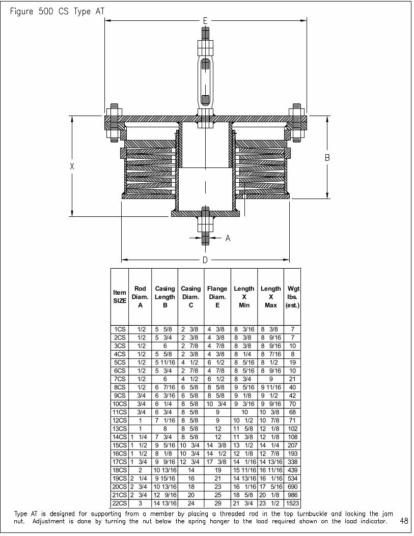
Item SIZE
Rod Diam.
A
Casing Length
B
Casing Diam.
C
Flange Diam.
E
Length X
Min
Length X
Max
Wgt lbs. (est.)
1CS 1/2 5 5/8 2 3/8 4 3/8 8 3/16 8 3/8 7
2CS 1/2 5 3/4 2 3/8 4 3/8 8 3/8 8 9/16 7
3CS 1/2 6 2 7/8 4 7/8 8 3/8 8 9/16 10
4CS 1/2 5 5/8 2 3/8 4 3/8 8 1/4 8 7/16 8
5CS 1/2 5 11/16 4 1/2 6 1/2 8 5/16 8 1/2 19
6CS 1/2 5 3/4 2 7/8 4 7/8 8 5/16 8 9/16 10
7CS 1/2 6 4 1/2 6 1/2 8 3/4 9 21
8CS 1/2 6 7/16 6 5/8 8 5/8 9 5/16 9 11/16 40
9CS 3/4 6 3/16 6 5/8 8 5/8 9 1/8 9 1/2 42
10CS 3/4 6 1/4 8 5/8 10 3/4 9 3/16 9 9/16 70
11CS 3/4 6 3/4 8 5/8 9 10 10 3/8 68
12CS 1 7 1/16 8 5/8 9 10 1/2 10 7/8 71
13CS 1 8 8 5/8 12 11 5/8 12 1/8 102
14CS 1 1/4 7 3/4 8 5/8 12 11 3/8 12 1/8 108
15CS 1 1/2 9 5/16 10 3/4 14 3/8 13 1/2 14 1/4 207
16CS 1 1/2 8 1/8 10 3/4 14 1/2 12 1/8 12 7/8 193
17CS 1 3/4 9 9/16 12 3/4 17 3/8 14 1/16 14 13/16 338
18CS 2 10 13/16 14 19 15 11/16 16 11/16 439
19CS 2 1/4 9 15/16 16 21 14 13/16 16 1/16 534
20CS 2 3/4 10 13/16 18 23 16 1/16 17 5/16 690
21CS 2 3/4 12 9/16 20 25 18 5/8 20 1/8 986
22CS 3 14 13/16 24 29 21 3/4 23 1/2 1523
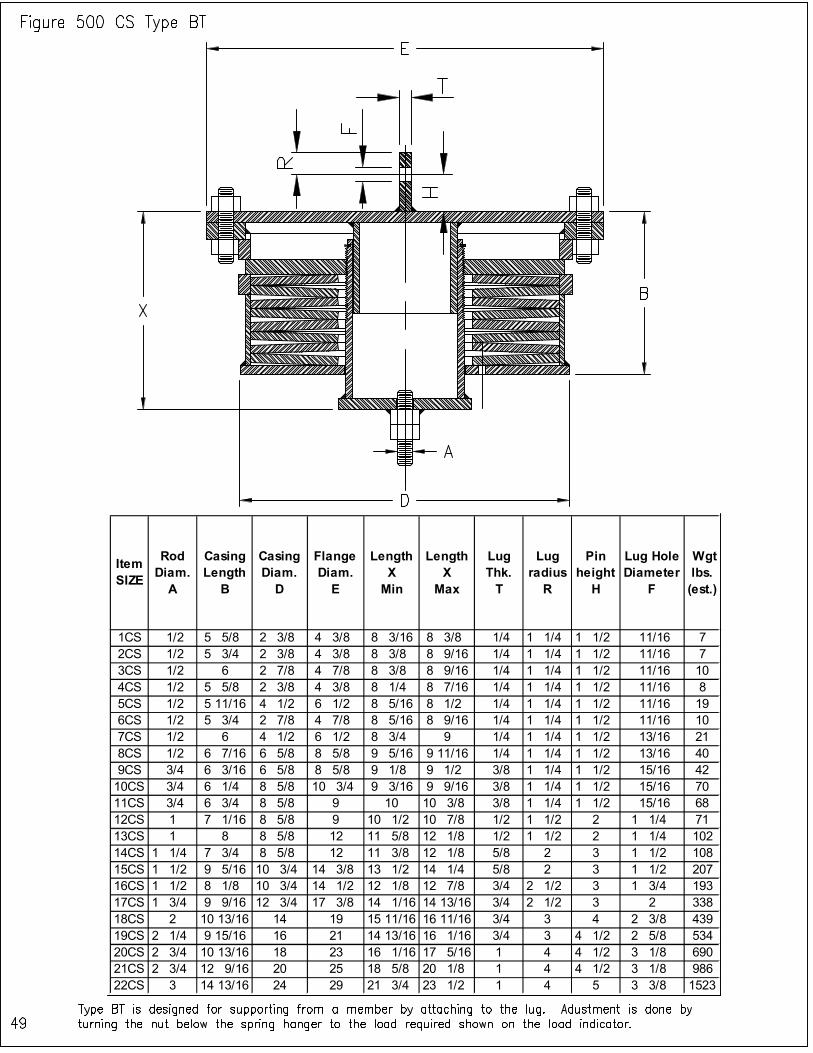
Item SIZE
Rod Diam.
A
Casing Length
B
Casing Diam.
D
Flange Diam.
E
Length X
Min
Length X
Max
Lug Thk. T
Lug radius
R
Pin height
H
Lug Hole Diameter
F
Wgt lbs. (est.)
1CS 1/2 5 5/8 2 3/8 4 3/8 8 3/16 8 3/8 1/4 1 1/4 1 1/2 11/16 7
2CS 1/2 5 3/4 2 3/8 4 3/8 8 3/8 8 9/16 1/4 1 1/4 1 1/2 11/16 7
3CS 1/2 6 2 7/8 4 7/8 8 3/8 8 9/16 1/4 1 1/4 1 1/2 11/16 10
4CS 1/2 5 5/8 2 3/8 4 3/8 8 1/4 8 7/16 1/4 1 1/4 1 1/2 11/16 8
5CS 1/2 5 11/16 4 1/2 6 1/2 8 5/16 8 1/2 1/4 1 1/4 1 1/2 11/16 19
6CS 1/2 5 3/4 2 7/8 4 7/8 8 5/16 8 9/16 1/4 1 1/4 1 1/2 11/16 10
7CS 1/2 6 4 1/2 6 1/2 8 3/4 9 1/4 1 1/4 1 1/2 13/16 21
8CS 1/2 6 7/16 6 5/8 8 5/8 9 5/16 9 11/16 1/4 1 1/4 1 1/2 13/16 40
9CS 3/4 6 3/16 6 5/8 8 5/8 9 1/8 9 1/2 3/8 1 1/4 1 1/2 15/16 42
10CS 3/4 6 1/4 8 5/8 10 3/4 9 3/16 9 9/16 3/8 1 1/4 1 1/2 15/16 70
11CS 3/4 6 3/4 8 5/8 9 10 10 3/8 3/8 1 1/4 1 1/2 15/16 68
12CS 1 7 1/16 8 5/8 9 10 1/2 10 7/8 1/2 1 1/2 2 1 1/4 71
13CS 1 8 8 5/8 12 11 5/8 12 1/8 1/2 1 1/2 2 1 1/4 102
14CS 1 1/4 7 3/4 8 5/8 12 11 3/8 12 1/8 5/8 2 3 1 1/2 108
15CS 1 1/2 9 5/16 10 3/4 14 3/8 13 1/2 14 1/4 5/8 2 3 1 1/2 207
16CS 1 1/2 8 1/8 10 3/4 14 1/2 12 1/8 12 7/8 3/4 2 1/2 3 1 3/4 193
17CS 1 3/4 9 9/16 12 3/4 17 3/8 14 1/16 14 13/16 3/4 2 1/2 3 2 338
18CS 2 10 13/16 14 19 15 11/16 16 11/16 3/4 3 4 2 3/8 439
19CS 2 1/4 9 15/16 16 21 14 13/16 16 1/16 3/4 3 4 1/2 2 5/8 534
20CS 2 3/4 10 13/16 18 23 16 1/16 17 5/16 1 4 4 1/2 3 1/8 690
21CS 2 3/4 12 9/16 20 25 18 5/8 20 1/8 1 4 4 1/2 3 1/8 986
22CS 3 14 13/16 24 29 21 3/4 23 1/2 1 4 5 3 3/8 1523
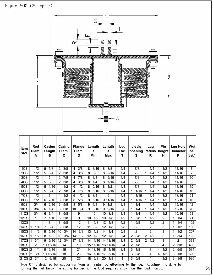
Item SIZE
Rod Diam. A
Casing Length
B
Casing Diam. C
Flange Diam. D
Length X Min
Length X
Max
Lug Thk. T
clevis opening
S
Lug radius
R
Pin height
H
Lug Hole Diameter
F
Wgt lbs. (est.)
1CS 1/2 5 5/8 2 3/8 4 3/8 8 3/16 8 3/8 1/4 7/8 1 1/4 1 1/2 11/16 7
2CS 1/2 5 3/4 2 3/8 4 3/8 8 3/8 8 9/16 1/4 7/8 1 1/4 1 1/2 11/16 7
3CS 1/2 6 2 7/8 4 7/8 8 3/8 8 9/16 1/4 7/8 1 1/4 1 1/2 11/16 10
4CS 1/2 5 5/8 2 3/8 4 3/8 8 1/4 8 7/16 1/4 7/8 1 1/4 1 1/2 11/16 8
5CS 1/2 5 11/16 4 1/2 6 1/2 8 5/16 8 1/2 1/4 7/8 1 1/4 1 1/2 11/16 19
6CS 1/2 5 3/4 2 7/8 4 7/8 8 5/16 8 9/16 1/4 1 1/16 1 1/4 1 1/2 11/16 10
7CS 1/2 6 4 1/2 6 1/2 8 3/4 9 1/4 1 1/16 1 1/4 1 1/2 13/16 21
8CS 1/2 6 7/16 6 5/8 8 5/8 9 5/16 9 11/16 1/4 1 1/16 1 1/4 1 1/2 13/16 40
9CS 3/4 6 3/16 6 5/8 8 5/8 9 1/8 9 1/2 3/8 1 1/4 1 1/4 1 1/2 15/16 42
10CS 3/4 6 1/4 8 5/8 10 3/4 9 3/16 9 9/16 3/8 1 1/4 1 1/4 1 1/2 15/16 70
11CS 3/4 6 3/4 8 5/8 9 10 10 3/8 3/8 1 1/4 1 1/4 1 1/2 15/16 68
12CS 1 7 1/16 8 5/8 9 10 1/2 10 7/8 1/2 1 5/8 1 1/2 2 1 1/4 71
13CS 1 8 8 5/8 12 11 5/8 12 1/8 1/2 1 5/8 1 1/2 2 1 1/4 102
14CS 1 1/4 7 3/4 8 5/8 12 11 3/8 12 1/8 5/8 2 2 3 1 1/2 108
15CS 1 1/2 9 5/16 10 3/4 14 3/8 13 1/2 14 1/4 5/8 2 2 3 1 1/2 207
16CS 1 1/2 8 1/8 10 3/4 14 1/2 12 1/8 12 7/8 3/4 2 3/8 2 1/2 3 1 3/4 193
17CS 1 3/4 9 9/16 12 3/4 17 3/8 14 1/16 14 13/16 3/4 2 5/8 2 1/2 3 2 338
18CS 2 10 13/16 14 19 15 11/16 16 11/16 3/4 2 7/8 3 4 2 3/8 439
19CS 2 1/4 9 15/16 16 21 14 13/16 16 1/16 3/4 3 1/8 3 4 1/2 2 5/8 534
20CS 2 3/4 10 13/16 18 23 16 1/16 17 5/16 1 3 3/8 4 4 1/2 3 1/8 690
21CS 2 3/4 12 9/16 20 25 18 5/8 20 1/8 1 3 5/8 4 4 1/2 3 1/8 986
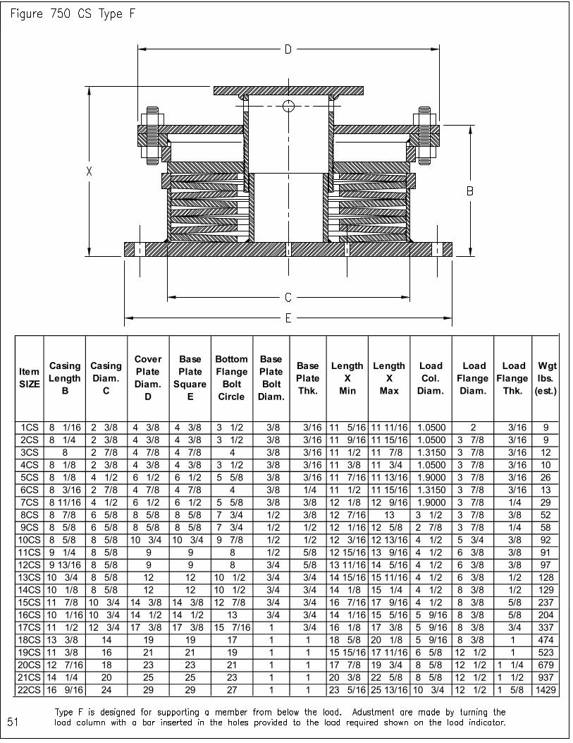
Item SIZE
Casing Length B
Casing Diam. C
Cover Plate Diam. D
Base Plate Square E
Bottom Flange Bolt Circle
Base Plate Bolt Diam.
Base Plate Thk.
Length X Min
Length X Max
Load Col. Diam.
Load Flange Diam.
Load Flange Thk.
Wgt lbs. (est.)
1CS 8 1/16 2 3/8 4 3/8 4 3/8 3 1/2 3/8 3/16 11 5/16 11 11/16 1.0500 2 3/16 9
2CS 8 1/4 2 3/8 4 3/8 4 3/8 3 1/2 3/8 3/16 11 9/16 11 15/16 1.0500 3 7/8 3/16 9
3CS 8 2 7/8 4 7/8 4 7/8 4 3/8 3/16 11 1/2 11 7/8 1.3150 3 7/8 3/16 12
4CS 8 1/8 2 3/8 4 3/8 4 3/8 3 1/2 3/8 3/16 11 3/8 11 3/4 1.0500 3 7/8 3/16 10
5CS 8 1/8 4 1/2 6 1/2 6 1/2 5 5/8 3/8 3/16 11 7/16 11 13/16 1.9000 3 7/8 3/16 26
6CS 8 3/16 2 7/8 4 7/8 4 7/8 4 3/8 1/4 11 1/2 11 15/16 1.3150 3 7/8 3/16 13
7CS 8 11/16 4 1/2 6 1/2 6 1/2 5 5/8 3/8 3/8 12 1/8 12 9/16 1.9000 3 7/8 1/4 29
8CS 8 7/8 6 5/8 8 5/8 8 5/8 7 3/4 1/2 3/8 12 7/16 13 3 1/2 3 7/8 3/8 52
9CS 8 5/8 6 5/8 8 5/8 8 5/8 7 3/4 1/2 1/2 12 1/16 12 5/8 2 7/8 3 7/8 1/4 58
10CS 8 5/8 8 5/8 10 3/4 10 3/4 9 7/8 1/2 1/2 12 3/16 12 13/16 4 1/2 5 3/4 3/8 92
11CS 9 1/4 8 5/8 9 9 8 1/2 5/8 12 15/16 13 9/16 4 1/2 6 3/8 3/8 91
12CS 9 13/16 8 5/8 9 9 8 3/4 5/8 13 11/16 14 5/16 4 1/2 6 3/8 3/8 97
13CS 10 3/4 8 5/8 12 12 10 1/2 3/4 3/4 14 15/16 15 11/16 4 1/2 6 3/8 1/2 128
14CS 10 1/8 8 5/8 12 12 10 1/2 3/4 3/4 14 1/8 15 1/4 4 1/2 8 3/8 1/2 129
15CS 11 7/8 10 3/4 14 3/8 14 3/8 12 7/8 3/4 3/4 16 7/16 17 9/16 4 1/2 8 3/8 5/8 237
16CS 10 1/16 10 3/4 14 1/2 14 1/2 13 3/4 3/4 14 1/16 15 5/16 5 9/16 8 3/8 5/8 204
17CS 11 1/2 12 3/4 17 3/8 17 3/8 15 7/16 1 3/4 16 1/8 17 3/8 5 9/16 8 3/8 3/4 337
18CS 13 3/8 14 19 19 17 1 1 18 5/8 20 1/8 5 9/16 8 3/8 1 474
19CS 11 3/8 16 21 21 19 1 1 15 15/16 17 11/16 6 5/8 12 1/2 1 523
20CS 12 7/16 18 23 23 21 1 1 17 7/8 19 3/4 8 5/8 12 1/2 1 1/4 679
21CS 14 1/4 20 25 25 23 1 1 20 3/8 22 5/8 8 5/8 12 1/2 1 1/2 937
22CS 16 9/16 24 29 29 27 1 1 23 5/16 25 13/16 10 3/4 12 1/2 1 5/8 1429

Item SIZE
Casing Length
B
Casing Diam. C
Flange Diam. D
Bottom Flange Square
E
Bottom Flange Bolt Circle
Base Plate Bolt Diam.
Bottom Flange Thk.
Length X Min
Length X
Max
Load Col. Diam.
Load Flange Diam.
Load Flange Thk.
Wgt lbs. (est.)
1CS 8 1/16 2 3/8 4 3/8 4 3/8 3 1/2 3/8 3/16 11 5/16 11 1/2 1.0500 2 3/16 9
2CS 8 1/4 2 3/8 4 3/8 4 3/8 3 1/2 3/8 3/16 11 9/16 11 3/4 1.0500 3 7/8 3/16 9
3CS 8 2 7/8 4 7/8 4 7/8 4 3/8 3/16 11 1/2 11 11/16 1.3150 3 7/8 3/16 12
4CS 8 1/8 2 3/8 4 3/8 4 3/8 3 1/2 3/8 3/16 11 3/8 11 9/16 1.0500 3 7/8 3/16 10
5CS 8 1/8 4 1/2 6 1/2 6 1/2 5 5/8 3/8 3/16 11 7/16 11 5/8 1.9000 3 7/8 3/16 26
6CS 8 3/16 2 7/8 4 7/8 4 7/8 4 3/8 1/4 11 1/2 11 3/4 1.3150 3 7/8 3/16 13
7CS 8 11/16 4 1/2 6 1/2 6 1/2 5 5/8 3/8 3/8 12 1/8 12 3/8 1.9000 3 7/8 1/4 29
8CS 8 7/8 6 5/8 8 5/8 8 5/8 7 3/4 1/2 3/8 12 7/16 12 13/16 3 1/2 3 7/8 3/8 52
9CS 8 5/8 6 5/8 8 5/8 8 5/8 7 3/4 1/2 1/2 12 1/16 12 7/16 2 7/8 3 7/8 1/4 58
10CS 8 5/8 8 5/8 10 3/4 10 3/4 9 7/8 1/2 1/2 12 1/8 12 1/2 4 1/2 5 3/4 3/8 92
11CS 9 1/4 8 5/8 9 9 8 1/2 5/8 12 7/8 13 1/4 4 1/2 6 3/8 3/8 91
12CS 9 13/16 8 5/8 9 9 8 3/4 5/8 13 11/16 14 1/16 4 1/2 6 3/8 3/8 96
13CS 10 3/4 8 5/8 12 12 10 1/2 3/4 3/4 14 15/16 15 7/16 4 1/2 6 3/8 1/2 128
14CS 10 1/8 8 5/8 12 12 10 1/2 3/4 3/4 14 1/8 14 7/8 4 1/2 8 3/8 1/2 129
15CS 11 7/8 10 3/4 14 3/8 14 3/8 12 7/8 3/4 3/4 16 7/16 17 3/16 4 1/2 8 3/8 5/8 237
16CS 10 1/16 10 3/4 14 1/2 14 1/2 13 3/4 3/4 13 15/16 14 11/16 5 9/16 8 3/8 5/8 204
17CS 11 1/2 12 3/4 17 3/8 17 3/8 15 7/16 1 3/4 16 1/8 16 7/8 5 9/16 8 3/8 3/4 336
18CS 13 3/8 14 19 19 17 1 1 18 5/8 19 5/8 5 9/16 8 3/8 1 473
19CS 11 3/8 16 21 21 19 1 1 15 15/16 17 3/16 6 5/8 12 1/2 1 522
20CS 12 7/16 18 23 23 21 1 1 17 7/8 19 1/8 8 5/8 12 1/2 1 1/4 677
21CS 14 1/4 20 25 25 23 1 1 20 3/8 21 7/8 8 5/8 12 1/2 1 1/2 935
22CS 16 9/16 24 29 29 27 1 1 23 5/16 25 1/16 10 3/4 12 1/2 1 5/8 1426
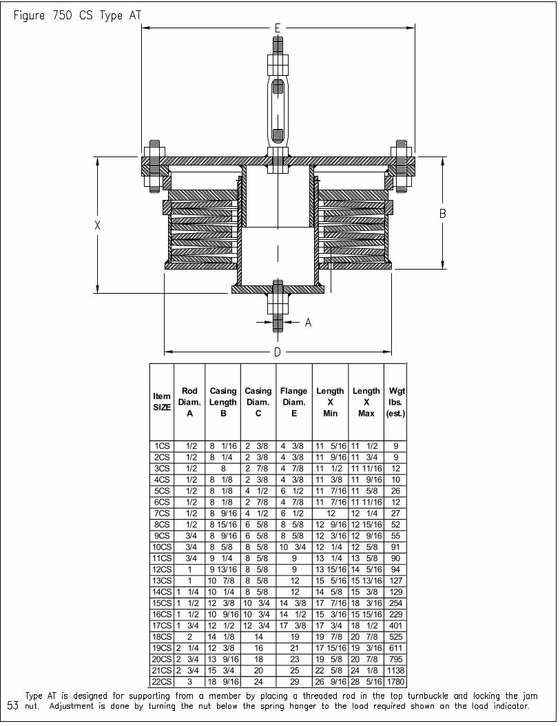
Item SIZE
Rod Diam.
A
Casing Length
B
Casing Diam.
C
Flange Diam.
E
Length X
Min
Length X
Max
Wgt lbs. (est.)
1CS 1/2 8 1/16 2 3/8 4 3/8 11 5/16 11 1/2 9
2CS 1/2 8 1/4 2 3/8 4 3/8 11 9/16 11 3/4 9
3CS 1/2 8 2 7/8 4 7/8 11 1/2 11 11/16 12
4CS 1/2 8 1/8 2 3/8 4 3/8 11 3/8 11 9/16 10
5CS 1/2 8 1/8 4 1/2 6 1/2 11 7/16 11 5/8 26
6CS 1/2 8 1/8 2 7/8 4 7/8 11 7/16 11 11/16 12
7CS 1/2 8 9/16 4 1/2 6 1/2 12 12 1/4 27
8CS 1/2 8 15/16 6 5/8 8 5/8 12 9/16 12 15/16 52
9CS 3/4 8 9/16 6 5/8 8 5/8 12 3/16 12 9/16 55
10CS 3/4 8 5/8 8 5/8 10 3/4 12 1/4 12 5/8 91
11CS 3/4 9 1/4 8 5/8 9 13 1/4 13 5/8 90
12CS 1 9 13/16 8 5/8 9 13 15/16 14 5/16 94
13CS 1 10 7/8 8 5/8 12 15 5/16 15 13/16 127
14CS 1 1/4 10 1/4 8 5/8 12 14 5/8 15 3/8 129
15CS 1 1/2 12 3/8 10 3/4 14 3/8 17 7/16 18 3/16 254
16CS 1 1/2 10 9/16 10 3/4 14 1/2 15 3/16 15 15/16 229
17CS 1 3/4 12 1/2 12 3/4 17 3/8 17 3/4 18 1/2 401
18CS 2 14 1/8 14 19 19 7/8 20 7/8 525
19CS 2 1/4 12 3/8 16 21 17 15/16 19 3/16 611
20CS 2 3/4 13 9/16 18 23 19 5/8 20 7/8 795
21CS 2 3/4 15 3/4 20 25 22 5/8 24 1/8 1138
22CS 3 18 9/16 24 29 26 9/16 28 5/16 1780
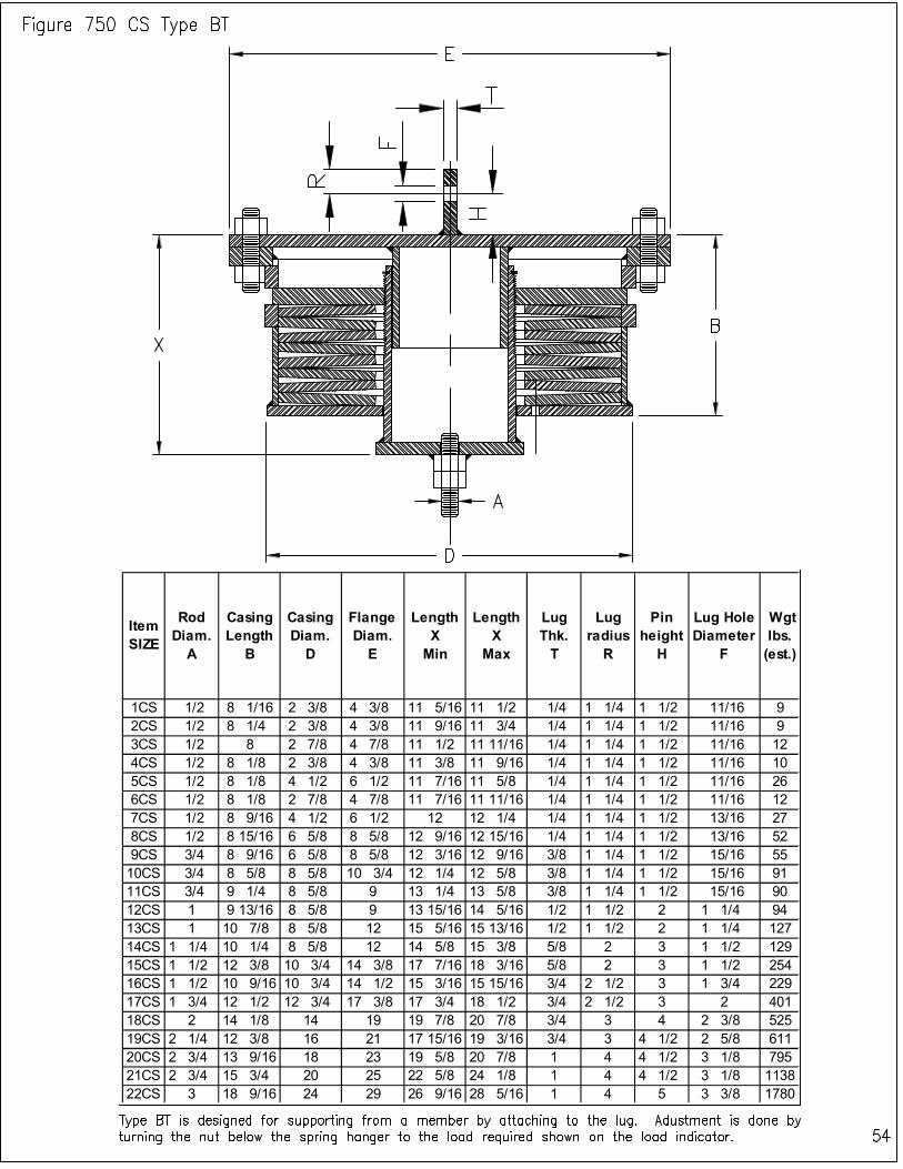
Item SIZE
Rod Diam.
A
Casing Length
B
Casing Diam.
D
Flange Diam.
E
Length X
Min
Length X
Max
Lug Thk. T
Lug radius
R
Pin height
H
Lug Hole Diameter
F
Wgt lbs. (est.)
1CS 1/2 8 1/16 2 3/8 4 3/8 11 5/16 11 1/2 1/4 1 1/4 1 1/2 11/16 9
2CS 1/2 8 1/4 2 3/8 4 3/8 11 9/16 11 3/4 1/4 1 1/4 1 1/2 11/16 9
3CS 1/2 8 2 7/8 4 7/8 11 1/2 11 11/16 1/4 1 1/4 1 1/2 11/16 12
4CS 1/2 8 1/8 2 3/8 4 3/8 11 3/8 11 9/16 1/4 1 1/4 1 1/2 11/16 10
5CS 1/2 8 1/8 4 1/2 6 1/2 11 7/16 11 5/8 1/4 1 1/4 1 1/2 11/16 26
6CS 1/2 8 1/8 2 7/8 4 7/8 11 7/16 11 11/16 1/4 1 1/4 1 1/2 11/16 12
7CS 1/2 8 9/16 4 1/2 6 1/2 12 12 1/4 1/4 1 1/4 1 1/2 13/16 27
8CS 1/2 8 15/16 6 5/8 8 5/8 12 9/16 12 15/16 1/4 1 1/4 1 1/2 13/16 52
9CS 3/4 8 9/16 6 5/8 8 5/8 12 3/16 12 9/16 3/8 1 1/4 1 1/2 15/16 55
10CS 3/4 8 5/8 8 5/8 10 3/4 12 1/4 12 5/8 3/8 1 1/4 1 1/2 15/16 91
11CS 3/4 9 1/4 8 5/8 9 13 1/4 13 5/8 3/8 1 1/4 1 1/2 15/16 90
12CS 1 9 13/16 8 5/8 9 13 15/16 14 5/16 1/2 1 1/2 2 1 1/4 94
13CS 1 10 7/8 8 5/8 12 15 5/16 15 13/16 1/2 1 1/2 2 1 1/4 127
14CS 1 1/4 10 1/4 8 5/8 12 14 5/8 15 3/8 5/8 2 3 1 1/2 129
15CS 1 1/2 12 3/8 10 3/4 14 3/8 17 7/16 18 3/16 5/8 2 3 1 1/2 254
16CS 1 1/2 10 9/16 10 3/4 14 1/2 15 3/16 15 15/16 3/4 2 1/2 3 1 3/4 229
17CS 1 3/4 12 1/2 12 3/4 17 3/8 17 3/4 18 1/2 3/4 2 1/2 3 2 401
18CS 2 14 1/8 14 19 19 7/8 20 7/8 3/4 3 4 2 3/8 525
19CS 2 1/4 12 3/8 16 21 17 15/16 19 3/16 3/4 3 4 1/2 2 5/8 611
20CS 2 3/4 13 9/16 18 23 19 5/8 20 7/8 1 4 4 1/2 3 1/8 795
21CS 2 3/4 15 3/4 20 25 22 5/8 24 1/8 1 4 4 1/2 3 1/8 1138
22CS 3 18 9/16 24 29 26 9/16 28 5/16 1 4 5 3 3/8 1780
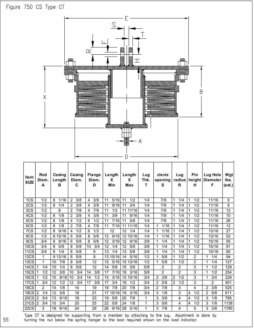
Item SIZE
Rod Diam. A
Casing Length
B
Casing Diam. C
Flange Diam. D
Length X Min
Length X
Max
Lug Thk. T
clevis opening
S
Lug radius
R
Pin height
H
Lug Hole Diameter
F
Wgt lbs. (est.)
1CS 1/2 8 1/16 2 3/8 4 3/8 11 5/16 11 1/2 1/4 7/8 1 1/4 1 1/2 11/16 9
2CS 1/2 8 1/4 2 3/8 4 3/8 11 9/16 11 3/4 1/4 7/8 1 1/4 1 1/2 11/16 9
3CS 1/2 8 2 7/8 4 7/8 11 1/2 11 11/16 1/4 7/8 1 1/4 1 1/2 11/16 12
4CS 1/2 8 1/8 2 3/8 4 3/8 11 3/8 11 9/16 1/4 7/8 1 1/4 1 1/2 11/16 10
5CS 1/2 8 1/8 4 1/2 6 1/2 11 7/16 11 5/8 1/4 7/8 1 1/4 1 1/2 11/16 26
6CS 1/2 8 1/8 2 7/8 4 7/8 11 7/16 11 11/16 1/4 1 1/16 1 1/4 1 1/2 11/16 12
7CS 1/2 8 9/16 4 1/2 6 1/2 12 12 1/4 1/4 1 1/16 1 1/4 1 1/2 13/16 27
8CS 1/2 8 15/16 6 5/8 8 5/8 12 9/16 12 15/16 1/4 1 1/16 1 1/4 1 1/2 13/16 52
9CS 3/4 8 9/16 6 5/8 8 5/8 12 3/16 12 9/16 3/8 1 1/4 1 1/4 1 1/2 15/16 55
10CS 3/4 8 5/8 8 5/8 10 3/4 12 1/4 12 5/8 3/8 1 1/4 1 1/4 1 1/2 15/16 91
11CS 3/4 9 1/4 8 5/8 9 13 1/4 13 5/8 3/8 1 1/4 1 1/4 1 1/2 15/16 90
12CS 1 9 13/16 8 5/8 9 13 15/16 14 5/16 1/2 1 5/8 1 1/2 2 1 1/4 94
13CS 1 10 7/8 8 5/8 12 15 5/16 15 13/16 1/2 1 5/8 1 1/2 2 1 1/4 127
14CS 1 1/4 10 1/4 8 5/8 12 14 5/8 15 3/8 5/8 2 2 3 1 1/2 129
15CS 1 1/2 12 3/8 10 3/4 14 3/8 17 7/16 18 3/16 5/8 2 2 3 1 1/2 254
16CS 1 1/2 10 9/16 10 3/4 14 1/2 15 3/16 15 15/16 3/4 2 3/8 2 1/2 3 1 3/4 229
17CS 1 3/4 12 1/2 12 3/4 17 3/8 17 3/4 18 1/2 3/4 2 5/8 2 1/2 3 2 401
18CS 2 14 1/8 14 19 19 7/8 20 7/8 3/4 2 7/8 3 4 2 3/8 525
19CS 2 1/4 12 3/8 16 21 17 15/16 19 3/16 3/4 3 1/8 3 4 1/2 2 5/8 611
20CS 2 3/4 13 9/16 18 23 19 5/8 20 7/8 1 3 3/8 4 4 1/2 3 1/8 795
21CS 2 3/4 15 3/4 20 25 22 5/8 24 1/8 1 3 5/8 4 4 1/2 3 1/8 1138
22CS 3 18 9/16 24 29 26 9/16 28 5/16 1 3 7/8 4 5 3 3/8 1780
Patent Pending, All Rights Reserved. 56
DST STAINLESS STEEL SPRING SUPPORT TYPES, FIGURES AND SIZES The overall dimensions of each figure type are provided in this section. DST Stainless Steel Spring Supports are divided into five displacement categories:
1) Figure 125 - Supports that will satisfy movements up to (1/8”), 2) Figure 250 - Supports that will satisfy movements up to (1/4”), 3) Figure 375 - Supports that will satisfy movements up to (3/8”), 4) Figure 500 - Supports that will satisfy movements up to (1/2”), 5) Figure 750 - Supports that will satisfy movements up to (3/4”).
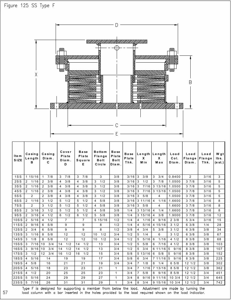
I te m S IZE
Ca sin g L e ng th
B
Ca sin g D ia m . C
Co ve r P la te D ia m . D
Ba se P la te S q u a re
E
Bo ttom F la n ge Bo l t C irc le
Ba se P la te Bo l t D ia m .
Ba se P la te T h k .
L e n g th X M in
L e ng th X
M a x
Lo a d Co l. D ia m .
Lo a d F la n g e D ia m .
L o a d F la n g e T h k .
W g t lb s. (e st. )
1S S 1 15 /16 1 7 /8 3 7 /8 3 7 /8 3 3 /8 3 /16 3 3 /8 3 3 /4 0 .8400 2 3 /16 3
2S S 2 1 /16 2 3 /8 4 3 /8 4 3 /8 3 1 /2 3 /8 3 /16 3 1 /2 3 7 /8 1 .0500 3 7 /8 3 /16 5
3S S 2 1 /16 2 3 /8 4 3 /8 4 3 /8 3 1 /2 3 /8 3 /16 3 7 /16 3 13 /16 1 .0500 3 7 /8 3 /16 5
4S S 2 1 /16 2 3 /8 4 3 /8 4 3 /8 3 1 /2 3 /8 3 /16 3 7 /16 3 13 /16 1 .0500 3 7 /8 3 /16 5
5S S 2 2 3 /8 4 3 /8 4 3 /8 3 1 /2 3 /8 3 /16 3 5 /8 4 1 .0500 3 7 /8 3 /16 5
6S S 2 1 /16 3 1 /2 5 1 /2 5 1 /2 4 5 /8 3 /8 3 /16 3 11 /16 4 1 /16 1 .6600 3 7 /8 3 /16 8
7S S 2 3 1 /2 5 1 /2 5 1 /2 4 5 /8 3 /8 3 /16 3 5 /8 4 1 .6600 3 7 /8 3 /16 8
8S S 2 3 /16 3 1 /2 5 1 /2 5 1 /2 4 5 /8 3 /8 1 /4 3 13 /16 4 1 /4 1 .6600 3 7 /8 3 /16 8
9S S 2 3 /16 4 1 /2 6 1 /2 6 1 /2 5 5 /8 3 /8 1 /4 3 15 /16 4 3 /8 1 .9000 3 7 /8 3 /16 12
10S S 2 5 /16 4 1 /2 7 7 5 15 /16 1 /2 1 /4 4 1 /16 4 9 /16 2 3 /8 5 3 /4 3 /16 15
11S S 2 9 /16 6 5 /8 9 9 8 1 /2 1 /4 4 5 /16 4 15 /16 3 1 /2 6 3 /8 1 /4 28
12S S 2 3 /4 6 5 /8 9 9 8 1 /2 3 /8 4 3 /4 5 3 /8 3 1 /2 6 3 /8 3 /8 34
13S S 3 1 /16 8 5 /8 12 12 10 1 /2 3 /4 1 /2 5 1 /4 6 3 1 /2 6 3 /8 3 /8 67
14S S 3 1 /8 8 5 /8 12 12 10 1 /2 3 /4 1 /2 5 5 /16 6 1 /16 4 1 /2 8 3 /8 3 /8 68
15S S 3 7 /16 10 3 /4 14 1 /2 14 1 /2 13 3 /4 1 /2 5 5 /8 6 7 /16 4 1 /2 8 3 /8 3 /8 103
16S S 3 9 /16 10 3 /4 14 1 /2 14 1 /2 13 3 /4 1 /2 5 3 /4 6 11 /16 5 9 /16 8 3 /8 3 /8 107
17S S 3 1 /2 12 3 /4 16 1 /2 16 1 /2 15 3 /4 5 /8 5 13 /16 6 5 /8 5 9 /16 8 3 /8 3 /8 152
18S S 4 5 /16 14 19 19 17 3 /4 5 /8 6 3 /4 7 11 /16 5 9 /16 8 3 /8 3 /8 225
19S S 4 5 /8 16 21 21 19 3 /4 3 /4 7 1 /8 8 1 /4 6 5 /8 12 1 /2 3 /8 302
20S S 4 5 /16 18 23 23 21 1 3 /4 7 1 /16 7 13 /16 8 5 /8 12 1 /2 3 /8 362
21S S 4 1 /2 20 25 25 23 1 3 /4 7 5 /8 8 9 /16 8 5 /8 12 1 /2 3 /4 451
22S S 5 5 /16 24 29 29 27 1 3 /4 8 9 /16 9 11 /16 10 3 /4 12 1 /2 3 /4 645
23S S 5 7 /16 26 31 31 29 1 3 /4 8 3 /4 9 15 /16 10 3 /4 12 1 /2 3 /4 742
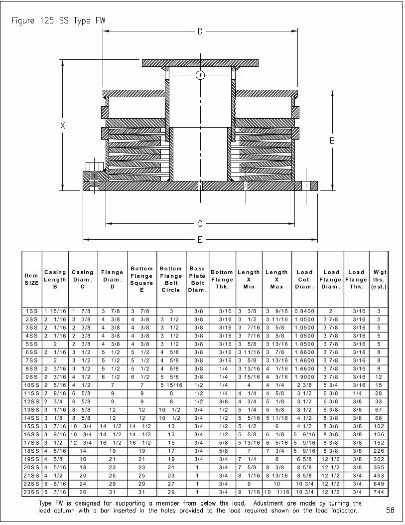
I te m S IZE
Ca sing L e ng th
B
Ca sing D ia m .
C
F la nge D ia m .
D
Bo ttom F la nge S qua re
E
Bo ttom F la nge Bo lt
C irc le
Ba se P la te Bo lt
D ia m .
Bo ttom F la nge Thk.
L e ng th X
M in
Le ng th X
M a x
Loa d Co l .
D ia m .
Loa d F la nge D ia m .
Loa d F la nge Thk .
W g t lb s. (e st. )
1S S 1 15 /16 1 7 /8 3 7 /8 3 7 /8 3 3/8 3 /16 3 3 /8 3 9 /16 0.8400 2 3 /16 3
2S S 2 1 /16 2 3 /8 4 3 /8 4 3 /8 3 1 /2 3/8 3 /16 3 1 /2 3 11/16 1.0500 3 7 /8 3 /16 5
3S S 2 1 /16 2 3 /8 4 3 /8 4 3 /8 3 1 /2 3/8 3 /16 3 7 /16 3 5 /8 1.0500 3 7 /8 3 /16 5
4S S 2 1 /16 2 3 /8 4 3 /8 4 3 /8 3 1 /2 3/8 3 /16 3 7 /16 3 5 /8 1.0500 3 7 /8 3 /16 5
5S S 2 2 3 /8 4 3 /8 4 3 /8 3 1 /2 3/8 3 /16 3 5 /8 3 13/16 1.0500 3 7 /8 3 /16 5
6S S 2 1 /16 3 1 /2 5 1 /2 5 1 /2 4 5 /8 3/8 3 /16 3 11/16 3 7 /8 1.6600 3 7 /8 3 /16 8
7S S 2 3 1 /2 5 1 /2 5 1 /2 4 5 /8 3/8 3 /16 3 5 /8 3 13/16 1.6600 3 7 /8 3 /16 8
8S S 2 3 /16 3 1 /2 5 1 /2 5 1 /2 4 5 /8 3/8 1 /4 3 13/16 4 1 /16 1.6600 3 7 /8 3 /16 8
9S S 2 3 /16 4 1 /2 6 1 /2 6 1 /2 5 5 /8 3/8 1 /4 3 15/16 4 3 /16 1.9000 3 7 /8 3 /16 12
10S S 2 5 /16 4 1 /2 7 7 5 15 /16 1/2 1 /4 4 4 1 /4 2 3 /8 5 3 /4 3 /16 15
11S S 2 9 /16 6 5 /8 9 9 8 1/2 1 /4 4 1 /4 4 5 /8 3 1 /2 6 3 /8 1 /4 28
12S S 2 3 /4 6 5 /8 9 9 8 1/2 3 /8 4 3 /4 5 1 /8 3 1 /2 6 3 /8 3 /8 33
13S S 3 1 /16 8 5 /8 12 12 10 1 /2 3/4 1 /2 5 1 /4 5 5 /8 3 1 /2 6 3 /8 3 /8 67
14S S 3 1 /8 8 5 /8 12 12 10 1 /2 3/4 1 /2 5 5 /16 5 11/16 4 1 /2 8 3 /8 3 /8 68
15S S 3 7 /16 10 3 /4 14 1 /2 14 1 /2 13 3/4 1 /2 5 1 /2 6 4 1 /2 8 3 /8 3 /8 102
16S S 3 9 /16 10 3 /4 14 1 /2 14 1 /2 13 3/4 1 /2 5 5 /8 6 1 /8 5 9 /16 8 3 /8 3 /8 106
17S S 3 1 /2 12 3 /4 16 1 /2 16 1 /2 15 3/4 5 /8 5 13/16 6 5 /16 5 9 /16 8 3 /8 3 /8 152
18S S 4 5 /16 14 19 19 17 3/4 5 /8 7 7 3 /4 5 9 /16 8 3 /8 3 /8 226
19S S 4 5 /8 16 21 21 19 3/4 3 /4 7 1 /4 8 6 5 /8 12 1 /2 3 /8 302
20S S 4 5 /16 18 23 23 21 1 3 /4 7 5 /8 8 3 /8 8 5 /8 12 1 /2 3 /8 365
21S S 4 1 /2 20 25 25 23 1 3 /4 8 1 /16 8 13/16 8 5 /8 12 1 /2 3 /4 453
22S S 5 5 /16 24 29 29 27 1 3 /4 9 10 10 3 /4 12 1 /2 3 /4 649
23S S 5 7 /16 26 31 31 29 1 3 /4 9 1 /16 10 1 /16 10 3 /4 12 1 /2 3 /4 744
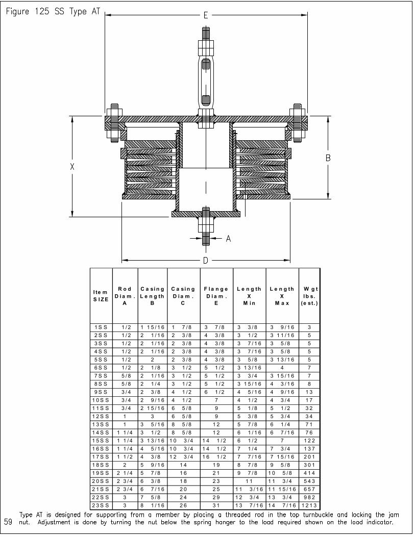
I te m S I ZE
R o d D i a m .
A
C a si n g L e n g th
B
C a sin g D i a m .
C
F l a n g e D i a m .
E
L e n g th X
M i n
L e n g th X
M a x
W g t l b s.
(e st. )
1 S S 1 / 2 1 1 5 / 1 6 1 7 / 8 3 7 / 8 3 3 / 8 3 9 / 1 6 3
2 S S 1 / 2 2 1 / 1 6 2 3 / 8 4 3 / 8 3 1 / 2 3 1 1 / 1 6 5
3 S S 1 / 2 2 1 / 1 6 2 3 / 8 4 3 / 8 3 7 / 1 6 3 5 / 8 5
4 S S 1 / 2 2 1 / 1 6 2 3 / 8 4 3 / 8 3 7 / 1 6 3 5 / 8 5
5 S S 1 / 2 2 2 3 / 8 4 3 / 8 3 5 / 8 3 1 3 / 1 6 5
6 S S 1 / 2 2 1 / 8 3 1 / 2 5 1 / 2 3 1 3 / 1 6 4 7
7 S S 5 / 8 2 1 / 1 6 3 1 / 2 5 1 / 2 3 3 / 4 3 1 5 / 1 6 7
8 S S 5 / 8 2 1 / 4 3 1 / 2 5 1 / 2 3 1 5 / 1 6 4 3 / 1 6 8
9 S S 3 / 4 2 3 / 8 4 1 / 2 6 1 / 2 4 5 / 1 6 4 9 / 1 6 1 3
1 0 S S 3 / 4 2 9 / 1 6 4 1 / 2 7 4 1 / 2 4 3 / 4 1 7
1 1 S S 3 / 4 2 1 5 / 1 6 6 5 / 8 9 5 1 / 8 5 1 / 2 3 2
1 2 S S 1 3 6 5 / 8 9 5 3 / 8 5 3 / 4 3 4
1 3 S S 1 3 5 / 1 6 8 5 / 8 1 2 5 7 / 8 6 1 / 4 7 1
1 4 S S 1 1 / 4 3 1 / 2 8 5 / 8 1 2 6 1 / 1 6 6 7 / 1 6 7 6
1 5 S S 1 1 / 4 3 1 3 / 1 6 1 0 3 / 4 1 4 1 / 2 6 1 / 2 7 1 2 2
1 6 S S 1 1 / 4 4 5 / 1 6 1 0 3 / 4 1 4 1 / 2 7 1 / 4 7 3 / 4 1 3 7
1 7 S S 1 1 / 2 4 3 / 8 1 2 3 / 4 1 6 1 / 2 7 7 / 1 6 7 1 5 / 1 6 2 0 1
1 8 S S 2 5 9 / 1 6 1 4 1 9 8 7 / 8 9 5 / 8 3 0 1
1 9 S S 2 1 / 4 5 7 / 8 1 6 2 1 9 7 / 8 1 0 5 / 8 4 1 4
2 0 S S 2 3 / 4 6 3 / 8 1 8 2 3 1 1 1 1 3 / 4 5 4 3
2 1 S S 2 3 / 4 6 7 / 1 6 2 0 2 5 1 1 3 / 1 6 1 1 1 5 / 1 6 6 5 7
2 2 S S 3 7 5 / 8 2 4 2 9 1 2 3 / 4 1 3 3 / 4 9 8 2
2 3 S S 3 8 1 / 1 6 2 6 3 1 1 3 7 / 1 6 1 4 7 / 1 6 1 2 1 3
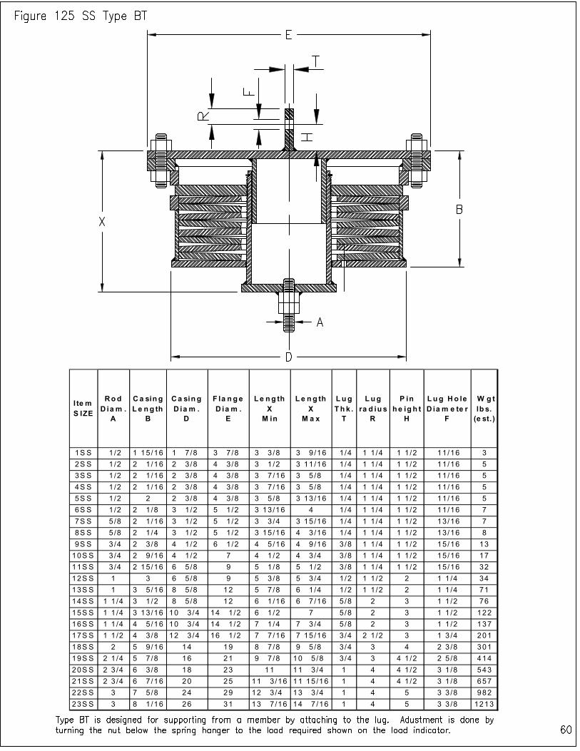
I te m S IZE
Rod D ia m .
A
Ca sin g L e ng th
B
Ca sin g D ia m .
D
F la ng e D ia m .
E
Le ng th X
M in
L e ng th X
M a x
Lug T h k .
T
Lug ra d iu s
R
P in he ig h t
H
Lug Ho le D ia m e te r
F
W g t lb s. (e st. )
1S S 1 /2 1 15 /16 1 7 /8 3 7 /8 3 3 /8 3 9 /16 1/4 1 1 /4 1 1 /2 11/16 3
2S S 1 /2 2 1 /16 2 3 /8 4 3 /8 3 1 /2 3 11 /16 1/4 1 1 /4 1 1 /2 11/16 5
3S S 1 /2 2 1 /16 2 3 /8 4 3 /8 3 7 /16 3 5 /8 1 /4 1 1 /4 1 1 /2 11/16 5
4S S 1 /2 2 1 /16 2 3 /8 4 3 /8 3 7 /16 3 5 /8 1 /4 1 1 /4 1 1 /2 11/16 5
5S S 1 /2 2 2 3 /8 4 3 /8 3 5 /8 3 13 /16 1/4 1 1 /4 1 1 /2 11/16 5
6S S 1 /2 2 1 /8 3 1 /2 5 1 /2 3 13 /16 4 1/4 1 1 /4 1 1 /2 11/16 7
7S S 5 /8 2 1 /16 3 1 /2 5 1 /2 3 3 /4 3 15 /16 1/4 1 1 /4 1 1 /2 13/16 7
8S S 5 /8 2 1 /4 3 1 /2 5 1 /2 3 15 /16 4 3 /16 1/4 1 1 /4 1 1 /2 13/16 8
9S S 3 /4 2 3 /8 4 1 /2 6 1 /2 4 5 /16 4 9 /16 3/8 1 1 /4 1 1 /2 15/16 13
10S S 3 /4 2 9 /16 4 1 /2 7 4 1 /2 4 3 /4 3 /8 1 1 /4 1 1 /2 15/16 17
11S S 3 /4 2 15 /16 6 5 /8 9 5 1 /8 5 1 /2 3 /8 1 1 /4 1 1 /2 15/16 32
12S S 1 3 6 5 /8 9 5 3 /8 5 3 /4 1 /2 1 1 /2 2 1 1 /4 34
13S S 1 3 5 /16 8 5 /8 12 5 7 /8 6 1 /4 1 /2 1 1 /2 2 1 1 /4 71
14S S 1 1 /4 3 1 /2 8 5 /8 12 6 1 /16 6 7 /16 5/8 2 3 1 1 /2 76
15S S 1 1 /4 3 13 /16 10 3 /4 14 1 /2 6 1 /2 7 5/8 2 3 1 1 /2 122
16S S 1 1 /4 4 5 /16 10 3 /4 14 1 /2 7 1 /4 7 3 /4 5 /8 2 3 1 1 /2 137
17S S 1 1 /2 4 3 /8 12 3 /4 16 1 /2 7 7 /16 7 15 /16 3/4 2 1 /2 3 1 3 /4 201
18S S 2 5 9 /16 14 19 8 7 /8 9 5 /8 3 /4 3 4 2 3 /8 301
19S S 2 1 /4 5 7 /8 16 21 9 7 /8 10 5 /8 3 /4 3 4 1 /2 2 5 /8 414
20S S 2 3 /4 6 3 /8 18 23 11 11 3 /4 1 4 4 1 /2 3 1 /8 543
21S S 2 3 /4 6 7 /16 20 25 11 3 /16 11 15 /16 1 4 4 1 /2 3 1 /8 657
22S S 3 7 5 /8 24 29 12 3 /4 13 3 /4 1 4 5 3 3 /8 982
23S S 3 8 1 /16 26 31 13 7 /16 14 7 /16 1 4 5 3 3 /8 1213
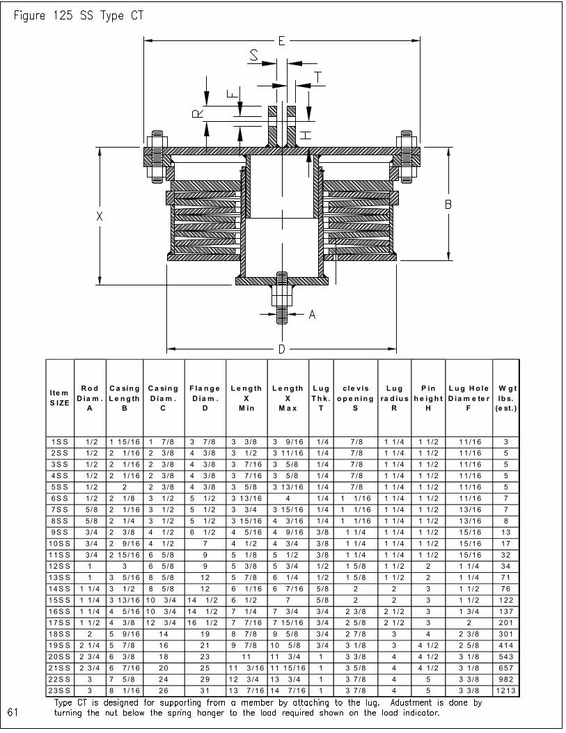
I te m S IZE
Ro d D ia m .
A
Ca sin g L e ng th
B
Ca sin g D ia m .
C
F la n g e D ia m .
D
L e ng th X
M in
L e ng th X
M a x
L ug T h k . T
c le v is o p e n in g
S
Lug ra d iu s
R
P in h e ig h t
H
L ug Ho le D ia m e te r
F
W g t lb s. (e st. )
1S S 1/2 1 15 /16 1 7 /8 3 7 /8 3 3 /8 3 9 /16 1 /4 7 /8 1 1 /4 1 1 /2 11 /16 3
2S S 1/2 2 1 /16 2 3 /8 4 3 /8 3 1 /2 3 11 /16 1 /4 7 /8 1 1 /4 1 1 /2 11 /16 5
3S S 1/2 2 1 /16 2 3 /8 4 3 /8 3 7 /16 3 5 /8 1 /4 7 /8 1 1 /4 1 1 /2 11 /16 5
4S S 1/2 2 1 /16 2 3 /8 4 3 /8 3 7 /16 3 5 /8 1 /4 7 /8 1 1 /4 1 1 /2 11 /16 5
5S S 1/2 2 2 3 /8 4 3 /8 3 5 /8 3 13 /16 1 /4 7 /8 1 1 /4 1 1 /2 11 /16 5
6S S 1/2 2 1 /8 3 1 /2 5 1 /2 3 13 /16 4 1 /4 1 1 /16 1 1 /4 1 1 /2 11 /16 7
7S S 5/8 2 1 /16 3 1 /2 5 1 /2 3 3 /4 3 15 /16 1 /4 1 1 /16 1 1 /4 1 1 /2 13 /16 7
8S S 5/8 2 1 /4 3 1 /2 5 1 /2 3 15 /16 4 3 /16 1 /4 1 1 /16 1 1 /4 1 1 /2 13 /16 8
9S S 3/4 2 3 /8 4 1 /2 6 1 /2 4 5 /16 4 9 /16 3 /8 1 1 /4 1 1 /4 1 1 /2 15 /16 13
10S S 3/4 2 9 /16 4 1 /2 7 4 1 /2 4 3 /4 3 /8 1 1 /4 1 1 /4 1 1 /2 15 /16 17
11S S 3/4 2 15 /16 6 5 /8 9 5 1 /8 5 1 /2 3 /8 1 1 /4 1 1 /4 1 1 /2 15 /16 32
12S S 1 3 6 5 /8 9 5 3 /8 5 3 /4 1 /2 1 5 /8 1 1 /2 2 1 1 /4 34
13S S 1 3 5 /16 8 5 /8 12 5 7 /8 6 1 /4 1 /2 1 5 /8 1 1 /2 2 1 1 /4 71
14S S 1 1 /4 3 1 /2 8 5 /8 12 6 1 /16 6 7 /16 5 /8 2 2 3 1 1 /2 76
15S S 1 1 /4 3 13 /16 10 3 /4 14 1 /2 6 1 /2 7 5 /8 2 2 3 1 1 /2 122
16S S 1 1 /4 4 5 /16 10 3 /4 14 1 /2 7 1 /4 7 3 /4 3 /4 2 3 /8 2 1 /2 3 1 3 /4 137
17S S 1 1 /2 4 3 /8 12 3 /4 16 1 /2 7 7 /16 7 15 /16 3 /4 2 5 /8 2 1 /2 3 2 201
18S S 2 5 9 /16 14 19 8 7 /8 9 5 /8 3 /4 2 7 /8 3 4 2 3 /8 301
19S S 2 1 /4 5 7 /8 16 21 9 7 /8 10 5 /8 3 /4 3 1 /8 3 4 1 /2 2 5 /8 414
20S S 2 3 /4 6 3 /8 18 23 11 11 3 /4 1 3 3 /8 4 4 1 /2 3 1 /8 543
21S S 2 3 /4 6 7 /16 20 25 11 3 /16 11 15 /16 1 3 5 /8 4 4 1 /2 3 1 /8 657
22S S 3 7 5 /8 24 29 12 3 /4 13 3 /4 1 3 7 /8 4 5 3 3 /8 982
23S S 3 8 1 /16 26 31 13 7 /16 14 7 /16 1 3 7 /8 4 5 3 3 /8 1213
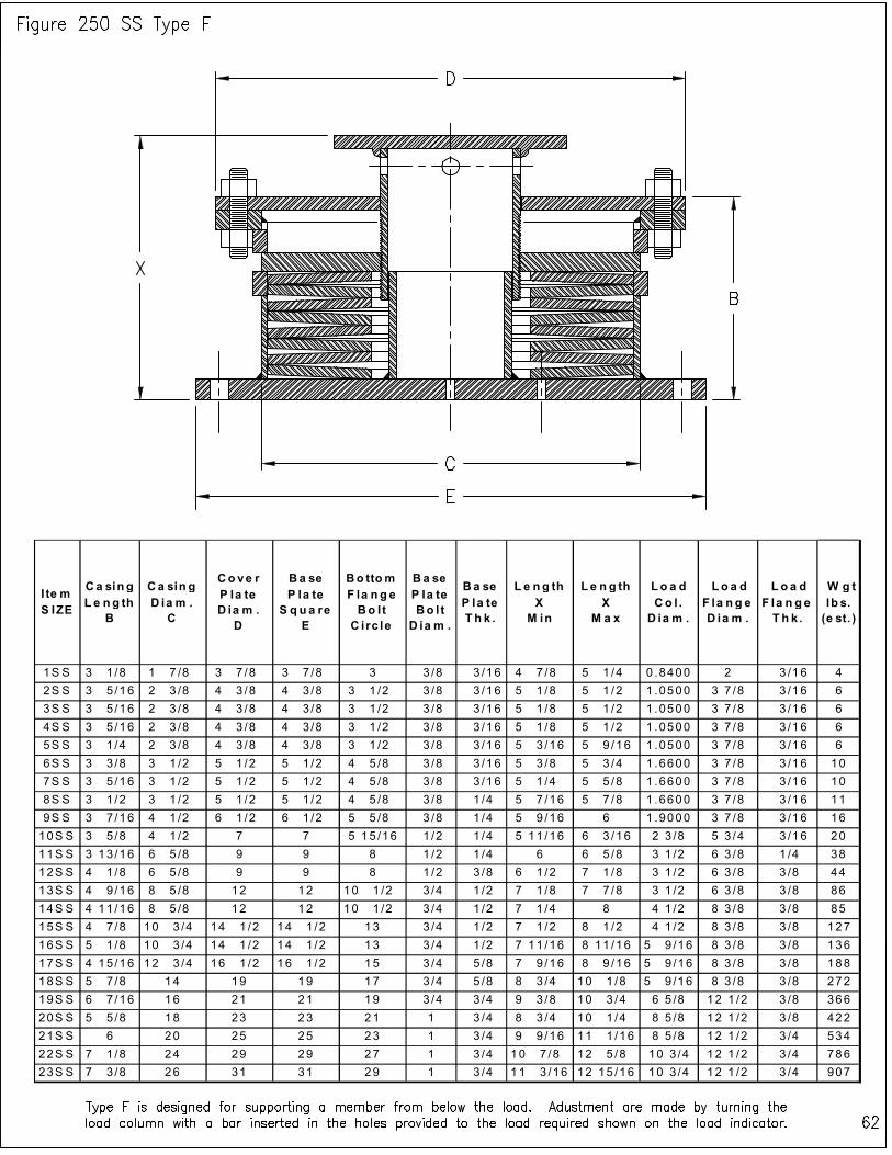
I te m S IZE
Ca sin g L e ng th
B
Ca sin g D ia m . C
Co ve r P la te D ia m . D
Ba se P la te S q u a re
E
Bo ttom F la n g e Bo lt C i rc le
Ba se P la te Bo l t D ia m .
Ba se P la te T h k .
L e ng th X M in
L e n g th X
M a x
Lo a d Co l . D ia m .
L o a d F la n g e D ia m .
L o a d F la n g e T h k .
W g t lb s. (e st. )
1S S 3 1 /8 1 7 /8 3 7 /8 3 7 /8 3 3 /8 3 /16 4 7 /8 5 1 /4 0 .8400 2 3 /16 4
2S S 3 5 /16 2 3 /8 4 3 /8 4 3 /8 3 1 /2 3 /8 3 /16 5 1 /8 5 1 /2 1 .0500 3 7 /8 3 /16 6
3S S 3 5 /16 2 3 /8 4 3 /8 4 3 /8 3 1 /2 3 /8 3 /16 5 1 /8 5 1 /2 1 .0500 3 7 /8 3 /16 6
4S S 3 5 /16 2 3 /8 4 3 /8 4 3 /8 3 1 /2 3 /8 3 /16 5 1 /8 5 1 /2 1 .0500 3 7 /8 3 /16 6
5S S 3 1 /4 2 3 /8 4 3 /8 4 3 /8 3 1 /2 3 /8 3 /16 5 3 /16 5 9 /16 1 .0500 3 7 /8 3 /16 6
6S S 3 3 /8 3 1 /2 5 1 /2 5 1 /2 4 5 /8 3 /8 3 /16 5 3 /8 5 3 /4 1 .6600 3 7 /8 3 /16 10
7S S 3 5 /16 3 1 /2 5 1 /2 5 1 /2 4 5 /8 3 /8 3 /16 5 1 /4 5 5 /8 1 .6600 3 7 /8 3 /16 10
8S S 3 1 /2 3 1 /2 5 1 /2 5 1 /2 4 5 /8 3 /8 1 /4 5 7 /16 5 7 /8 1 .6600 3 7 /8 3 /16 11
9S S 3 7 /16 4 1 /2 6 1 /2 6 1 /2 5 5 /8 3 /8 1 /4 5 9 /16 6 1 .9000 3 7 /8 3 /16 16
10S S 3 5 /8 4 1 /2 7 7 5 15 /16 1 /2 1 /4 5 11 /16 6 3 /16 2 3 /8 5 3 /4 3 /16 20
11S S 3 13 /16 6 5 /8 9 9 8 1 /2 1 /4 6 6 5 /8 3 1 /2 6 3 /8 1 /4 38
12S S 4 1 /8 6 5 /8 9 9 8 1 /2 3 /8 6 1 /2 7 1 /8 3 1 /2 6 3 /8 3 /8 44
13S S 4 9 /16 8 5 /8 12 12 10 1 /2 3 /4 1 /2 7 1 /8 7 7 /8 3 1 /2 6 3 /8 3 /8 86
14S S 4 11 /16 8 5 /8 12 12 10 1 /2 3 /4 1 /2 7 1 /4 8 4 1 /2 8 3 /8 3 /8 85
15S S 4 7 /8 10 3 /4 14 1 /2 14 1 /2 13 3 /4 1 /2 7 1 /2 8 1 /2 4 1 /2 8 3 /8 3 /8 127
16S S 5 1 /8 10 3 /4 14 1 /2 14 1 /2 13 3 /4 1 /2 7 11 /16 8 11 /16 5 9 /16 8 3 /8 3 /8 136
17S S 4 15 /16 12 3 /4 16 1 /2 16 1 /2 15 3 /4 5 /8 7 9 /16 8 9 /16 5 9 /16 8 3 /8 3 /8 188
18S S 5 7 /8 14 19 19 17 3 /4 5 /8 8 3 /4 10 1 /8 5 9 /16 8 3 /8 3 /8 272
19S S 6 7 /16 16 21 21 19 3 /4 3 /4 9 3 /8 10 3 /4 6 5 /8 12 1 /2 3 /8 366
20S S 5 5 /8 18 23 23 21 1 3 /4 8 3 /4 10 1 /4 8 5 /8 12 1 /2 3 /8 422
21S S 6 20 25 25 23 1 3 /4 9 9 /16 11 1 /16 8 5 /8 12 1 /2 3 /4 534
22S S 7 1 /8 24 29 29 27 1 3 /4 10 7 /8 12 5 /8 10 3 /4 12 1 /2 3 /4 786
23S S 7 3 /8 26 31 31 29 1 3 /4 11 3 /16 12 15 /16 10 3 /4 12 1 /2 3 /4 907
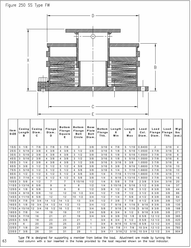
I te m S IZE
Ca sin g L e ng th
B
Ca sin g D ia m .
C
F la n g e D ia m .
D
Bo ttom F la n g e S qu a re
E
Bo ttom F la n g e Bo lt
C irc le
Ba se P la te Bo l t
D ia m .
Bo ttom F la n g e T h k .
L e ng th X
M in
L e ng th X
M a x
Lo a d Co l .
D ia m .
L o a d F la n g e D ia m .
L o a d F la n g e T h k.
W g t lb s. (e st. )
1S S 3 1 /8 1 7 /8 3 7 /8 3 7 /8 3 3 /8 3 /16 4 7 /8 5 1 /16 0 .8400 2 3/16 4
2S S 3 5 /16 2 3 /8 4 3 /8 4 3 /8 3 1 /2 3 /8 3 /16 5 1 /8 5 5 /16 1 .0500 3 7 /8 3 /16 6
3S S 3 5 /16 2 3 /8 4 3 /8 4 3 /8 3 1 /2 3 /8 3 /16 5 1 /8 5 5 /16 1 .0500 3 7 /8 3 /16 6
4S S 3 5 /16 2 3 /8 4 3 /8 4 3 /8 3 1 /2 3 /8 3 /16 5 1 /8 5 5 /16 1 .0500 3 7 /8 3 /16 6
5S S 3 1 /4 2 3 /8 4 3 /8 4 3 /8 3 1 /2 3 /8 3 /16 5 3 /16 5 3 /8 1 .0500 3 7 /8 3 /16 6
6S S 3 3 /8 3 1 /2 5 1 /2 5 1 /2 4 5 /8 3 /8 3 /16 5 3 /8 5 9 /16 1 .6600 3 7 /8 3 /16 10
7S S 3 5 /16 3 1 /2 5 1 /2 5 1 /2 4 5 /8 3 /8 3 /16 5 1 /4 5 7 /16 1 .6600 3 7 /8 3 /16 10
8S S 3 1 /2 3 1 /2 5 1 /2 5 1 /2 4 5 /8 3 /8 1 /4 5 7 /16 5 11 /16 1 .6600 3 7 /8 3 /16 11
9S S 3 7 /16 4 1 /2 6 1 /2 6 1 /2 5 5 /8 3 /8 1 /4 5 9 /16 5 13 /16 1 .9000 3 7 /8 3 /16 16
10S S 3 5 /8 4 1 /2 7 7 5 15 /16 1 /2 1 /4 5 5 /8 5 7 /8 2 3 /8 5 3 /4 3 /16 20
11S S 3 13 /16 6 5 /8 9 9 8 1 /2 1 /4 5 15 /16 6 5 /16 3 1 /2 6 3 /8 1 /4 37
12S S 4 1 /8 6 5 /8 9 9 8 1 /2 3 /8 6 1 /2 6 7 /8 3 1 /2 6 3 /8 3 /8 44
13S S 4 9 /16 8 5 /8 12 12 10 1 /2 3 /4 1 /2 7 1 /8 7 1 /2 3 1 /2 6 3 /8 3 /8 86
14S S 4 11 /16 8 5 /8 12 12 10 1 /2 3 /4 1 /2 7 1 /4 7 5 /8 4 1 /2 8 3 /8 3 /8 84
15S S 4 7 /8 10 3 /4 14 1 /2 14 1 /2 13 3 /4 1 /2 7 3 /8 7 7 /8 4 1 /2 8 3 /8 3 /8 127
16S S 5 1 /8 10 3 /4 14 1 /2 14 1 /2 13 3 /4 1 /2 7 9 /16 8 1 /16 5 9 /16 8 3 /8 3 /8 135
17S S 4 15 /16 12 3 /4 16 1 /2 16 1 /2 15 3 /4 5 /8 7 9 /16 8 1 /16 5 9 /16 8 3 /8 3 /8 188
18S S 5 7 /8 14 19 19 17 3 /4 5 /8 8 3 /4 9 1 /2 5 9 /16 8 3 /8 3 /8 271
19S S 6 7 /16 16 21 21 19 3 /4 3 /4 9 3 /8 10 1 /8 6 5 /8 12 1 /2 3 /8 365
20S S 5 5 /8 18 23 23 21 1 3/4 8 3 /4 9 1 /2 8 5 /8 12 1 /2 3 /8 420
21S S 6 20 25 25 23 1 3/4 9 9 /16 10 5 /16 8 5 /8 12 1 /2 3 /4 532
22S S 7 1 /8 24 29 29 27 1 3/4 10 7 /8 11 7 /8 10 3 /4 12 1 /2 3 /4 783
23S S 7 3 /8 26 31 31 29 1 3/4 11 3 /16 12 3 /16 10 3 /4 12 1 /2 3 /4 904
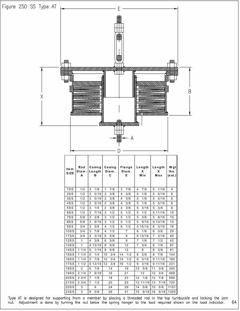
I te m S IZE
Rod Dia m .
A
Ca sing Le ngth
B
Ca sing Dia m .
C
Fla nge Dia m .
E
Le ngth X
M in
Le ngth X
M a x
W gt lbs.
(e st.)
1SS 1/2 3 1/8 1 7/8 3 7/8 4 7/8 5 1/16 4
2SS 1/2 3 5/16 2 3/8 4 3/8 5 1/8 5 5/16 6
3SS 1/2 3 5/16 2 3/8 4 3/8 5 1/8 5 5/16 6
4SS 1/2 3 5/16 2 3/8 4 3/8 5 1/8 5 5/16 6
5SS 1/2 3 1/4 2 3/8 4 3/8 5 3/16 5 3/8 6
6SS 1/2 3 7/16 3 1/2 5 1/2 5 1/2 5 11/16 10
7SS 5/8 3 3/8 3 1/2 5 1/2 5 3/8 5 9/16 10
8SS 5/8 3 9/16 3 1/2 5 1/2 5 9/16 5 13/16 10
9SS 3/4 3 5/8 4 1/2 6 1/2 5 15/16 6 3/16 16
10SS 3/4 3 7/8 4 1/2 7 6 1/8 6 3/8 20
11SS 3/4 4 3/16 6 5/8 9 6 13/16 7 3/16 40
12SS 1 4 3/8 6 5/8 9 7 1/8 7 1/2 42
13SS 1 4 13/16 8 5/8 12 7 3/4 8 1/8 87
14SS 1 1/4 5 1/16 8 5/8 12 8 8 3/8 91
15SS 1 1/4 5 1/4 10 3/4 14 1/2 8 3/8 8 7/8 144
16SS 1 1/4 5 7/8 10 3/4 14 1/2 9 3/16 9 11/16 160
17SS 1 1/2 5 13/16 12 3/4 16 1/2 9 3/16 9 11/16 231
18SS 2 6 7/8 14 19 10 5/8 11 3/8 340
19SS 2 1/4 7 9/16 16 21 12 12 3/4 469
20SS 2 3/4 7 1/8 18 23 12 1/8 12 7/8 590
21SS 2 3/4 7 1/2 20 25 12 11/16 13 7/16 725
22SS 3 9 24 29 14 5/8 15 5/8 1101
23SS 3 9 5/8 26 31 15 9/16 16 9/16 1355
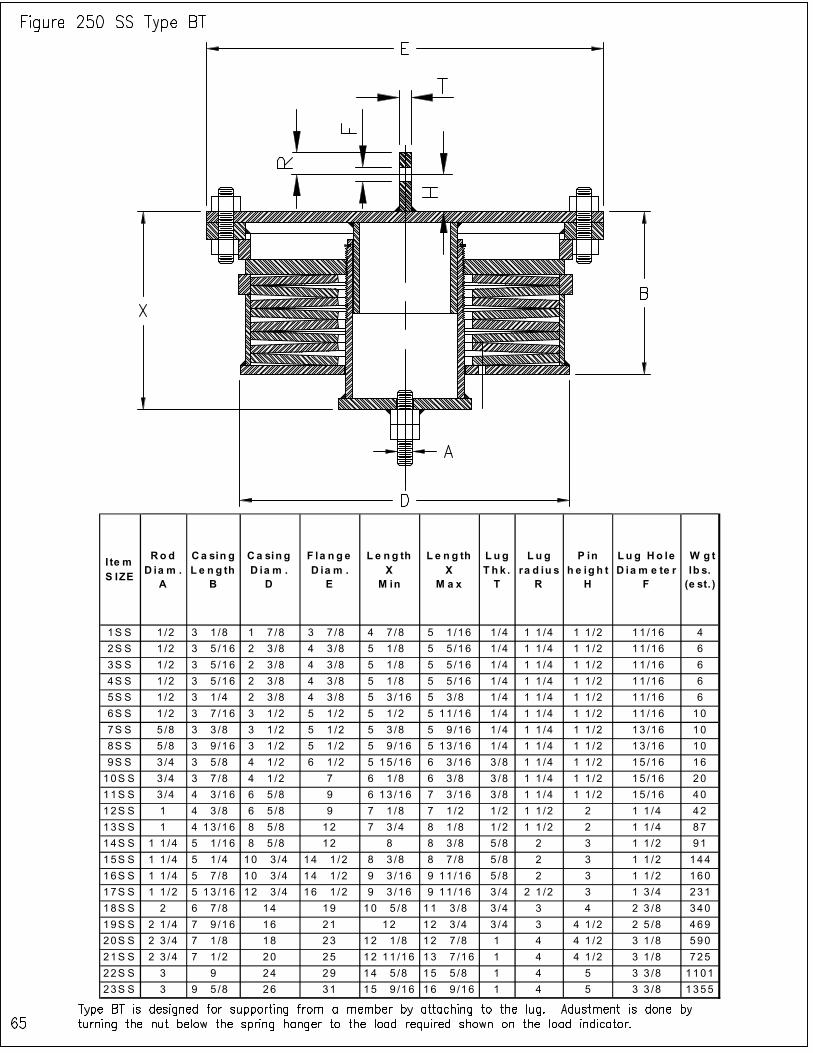
I te m S IZE
Ro d D ia m .
A
Ca sin g L e n g th
B
Ca sin g D ia m .
D
F la n g e D ia m .
E
L e ng th X
M in
L e n g th X
M a x
L u g T h k .
T
L u g ra d iu s
R
P in h e ig h t
H
Lu g Ho le D ia m e te r
F
W g t lb s.
(e st. )
1S S 1 /2 3 1 /8 1 7 /8 3 7 /8 4 7 /8 5 1 /16 1 /4 1 1 /4 1 1 /2 11 /16 4
2S S 1 /2 3 5 /16 2 3 /8 4 3 /8 5 1 /8 5 5 /16 1 /4 1 1 /4 1 1 /2 11 /16 6
3S S 1 /2 3 5 /16 2 3 /8 4 3 /8 5 1 /8 5 5 /16 1 /4 1 1 /4 1 1 /2 11 /16 6
4S S 1 /2 3 5 /16 2 3 /8 4 3 /8 5 1 /8 5 5 /16 1 /4 1 1 /4 1 1 /2 11 /16 6
5S S 1 /2 3 1 /4 2 3 /8 4 3 /8 5 3 /16 5 3 /8 1 /4 1 1 /4 1 1 /2 11 /16 6
6S S 1 /2 3 7 /16 3 1 /2 5 1 /2 5 1 /2 5 11 /16 1 /4 1 1 /4 1 1 /2 11 /16 10
7S S 5 /8 3 3 /8 3 1 /2 5 1 /2 5 3 /8 5 9 /16 1 /4 1 1 /4 1 1 /2 13 /16 10
8S S 5 /8 3 9 /16 3 1 /2 5 1 /2 5 9 /16 5 13 /16 1 /4 1 1 /4 1 1 /2 13 /16 10
9S S 3 /4 3 5 /8 4 1 /2 6 1 /2 5 15 /16 6 3 /16 3 /8 1 1 /4 1 1 /2 15 /16 16
10S S 3 /4 3 7 /8 4 1 /2 7 6 1 /8 6 3 /8 3 /8 1 1 /4 1 1 /2 15 /16 20
11S S 3 /4 4 3 /16 6 5 /8 9 6 13 /16 7 3 /16 3 /8 1 1 /4 1 1 /2 15 /16 40
12S S 1 4 3 /8 6 5 /8 9 7 1 /8 7 1 /2 1 /2 1 1 /2 2 1 1 /4 42
13S S 1 4 13 /16 8 5 /8 12 7 3 /4 8 1 /8 1 /2 1 1 /2 2 1 1 /4 87
14S S 1 1 /4 5 1 /16 8 5 /8 12 8 8 3 /8 5 /8 2 3 1 1 /2 91
15S S 1 1 /4 5 1 /4 10 3 /4 14 1 /2 8 3 /8 8 7 /8 5 /8 2 3 1 1 /2 144
16S S 1 1 /4 5 7 /8 10 3 /4 14 1 /2 9 3 /16 9 11 /16 5 /8 2 3 1 1 /2 160
17S S 1 1 /2 5 13 /16 12 3 /4 16 1 /2 9 3 /16 9 11 /16 3 /4 2 1 /2 3 1 3 /4 231
18S S 2 6 7 /8 14 19 10 5 /8 11 3 /8 3 /4 3 4 2 3 /8 340
19S S 2 1 /4 7 9 /16 16 21 12 12 3 /4 3 /4 3 4 1 /2 2 5 /8 469
20S S 2 3 /4 7 1 /8 18 23 12 1 /8 12 7 /8 1 4 4 1 /2 3 1 /8 590
21S S 2 3 /4 7 1 /2 20 25 12 11 /16 13 7 /16 1 4 4 1 /2 3 1 /8 725
22S S 3 9 24 29 14 5 /8 15 5 /8 1 4 5 3 3 /8 1101
23S S 3 9 5 /8 26 31 15 9 /16 16 9 /16 1 4 5 3 3 /8 1355
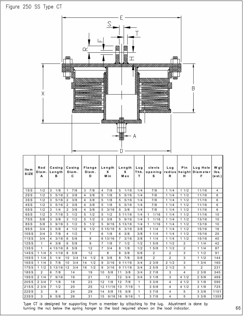
I te m S IZE
Rod D ia m .
A
Ca sin g L e ng th
B
Ca sin g D ia m .
C
F la ng e D ia m .
D
L e n g th X
M in
L e ng th X
M a x
Lug T h k . T
c le v is o p e n in g
S
L ug ra d iu s
R
P in h e ig h t
H
Lug Ho le D ia m e te r
F
W g t lb s. (e st. )
1S S 1 /2 3 1 /8 1 7 /8 3 7 /8 4 7 /8 5 1 /16 1 /4 7 /8 1 1 /4 1 1 /2 11 /16 4
2S S 1 /2 3 5 /16 2 3 /8 4 3 /8 5 1 /8 5 5 /16 1 /4 7 /8 1 1 /4 1 1 /2 11 /16 6
3S S 1 /2 3 5 /16 2 3 /8 4 3 /8 5 1 /8 5 5 /16 1 /4 7 /8 1 1 /4 1 1 /2 11 /16 6
4S S 1 /2 3 5 /16 2 3 /8 4 3 /8 5 1 /8 5 5 /16 1 /4 7 /8 1 1 /4 1 1 /2 11 /16 6
5S S 1 /2 3 1 /4 2 3 /8 4 3 /8 5 3 /16 5 3 /8 1 /4 7 /8 1 1 /4 1 1 /2 11 /16 6
6S S 1 /2 3 7 /16 3 1 /2 5 1 /2 5 1 /2 5 11 /16 1 /4 1 1 /16 1 1 /4 1 1 /2 11 /16 10
7S S 5 /8 3 3 /8 3 1 /2 5 1 /2 5 3 /8 5 9 /16 1 /4 1 1 /16 1 1 /4 1 1 /2 13 /16 10
8S S 5 /8 3 9 /16 3 1 /2 5 1 /2 5 9 /16 5 13 /16 1 /4 1 1 /16 1 1 /4 1 1 /2 13 /16 10
9S S 3 /4 3 5 /8 4 1 /2 6 1 /2 5 15 /16 6 3 /16 3 /8 1 1 /4 1 1 /4 1 1 /2 15 /16 16
10S S 3 /4 3 7 /8 4 1 /2 7 6 1 /8 6 3 /8 3 /8 1 1 /4 1 1 /4 1 1 /2 15 /16 20
11S S 3 /4 4 3 /16 6 5 /8 9 6 13 /16 7 3 /16 3 /8 1 1 /4 1 1 /4 1 1 /2 15 /16 40
12S S 1 4 3 /8 6 5 /8 9 7 1 /8 7 1 /2 1 /2 1 5 /8 1 1 /2 2 1 1 /4 42
13S S 1 4 13 /16 8 5 /8 12 7 3 /4 8 1 /8 1 /2 1 5 /8 1 1 /2 2 1 1 /4 87
14S S 1 1 /4 5 1 /16 8 5 /8 12 8 8 3 /8 5 /8 2 2 3 1 1 /2 91
15S S 1 1 /4 5 1 /4 10 3 /4 14 1 /2 8 3 /8 8 7 /8 5 /8 2 2 3 1 1 /2 144
16S S 1 1 /4 5 7 /8 10 3 /4 14 1 /2 9 3 /16 9 11 /16 3 /4 2 3 /8 2 1 /2 3 1 3 /4 160
17S S 1 1 /2 5 13 /16 12 3 /4 16 1 /2 9 3 /16 9 11 /16 3 /4 2 5 /8 2 1 /2 3 2 231
18S S 2 6 7 /8 14 19 10 5 /8 11 3 /8 3 /4 2 7 /8 3 4 2 3 /8 340
19S S 2 1 /4 7 9 /16 16 21 12 12 3 /4 3 /4 3 1 /8 3 4 1 /2 2 5 /8 469
20S S 2 3 /4 7 1 /8 18 23 12 1 /8 12 7 /8 1 3 3 /8 4 4 1 /2 3 1 /8 590
21S S 2 3 /4 7 1 /2 20 25 12 11 /16 13 7 /16 1 3 5 /8 4 4 1 /2 3 1 /8 725
22S S 3 9 24 29 14 5 /8 15 5 /8 1 3 7 /8 4 5 3 3 /8 1101
23S S 3 9 5 /8 26 31 15 9 /16 16 9 /16 1 3 7 /8 4 5 3 3 /8 1355
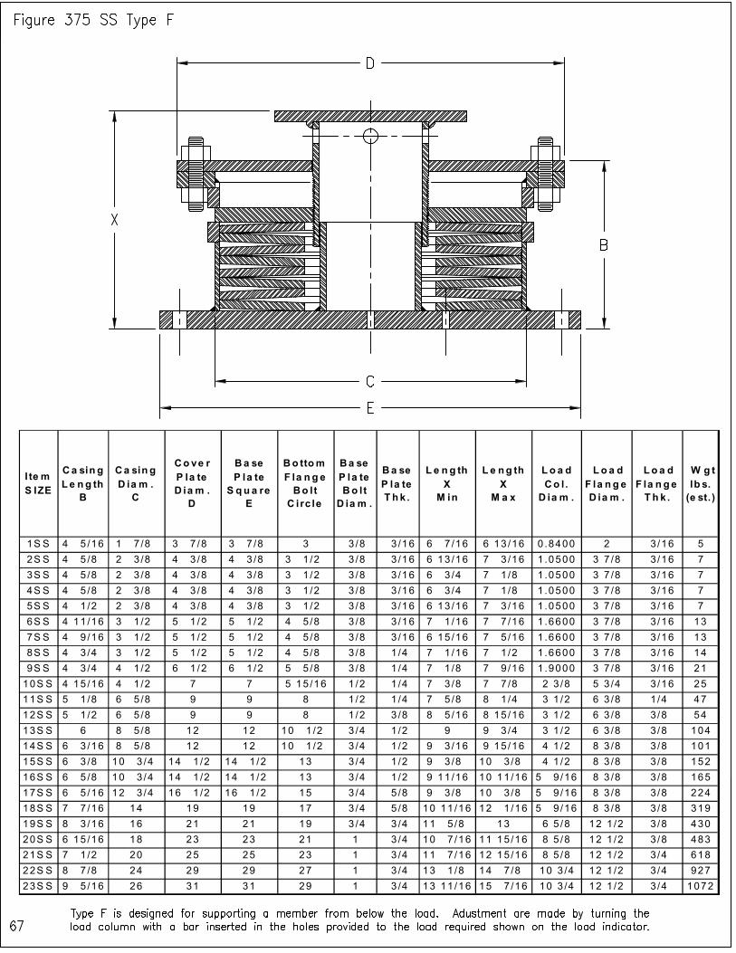
I te m S IZE
Ca sin g L e ng th
B
Ca sin g D ia m . C
Co ve r P la te D ia m . D
Ba se P la te S qu a re
E
Bo ttom F la n g e Bo lt C i rc le
Ba se P la te Bo lt D ia m .
Ba se P la te T hk .
L e ng th X M in
L e ng th X
M a x
Lo a d Co l . D ia m .
L o a d F la n g e D ia m .
Lo a d F la n ge T h k .
W g t lb s. (e st. )
1S S 4 5 /16 1 7 /8 3 7 /8 3 7 /8 3 3 /8 3 /16 6 7 /16 6 13 /16 0 .8400 2 3/16 5
2S S 4 5 /8 2 3 /8 4 3 /8 4 3 /8 3 1 /2 3 /8 3 /16 6 13 /16 7 3 /16 1 .0500 3 7 /8 3/16 7
3S S 4 5 /8 2 3 /8 4 3 /8 4 3 /8 3 1 /2 3 /8 3 /16 6 3 /4 7 1 /8 1 .0500 3 7 /8 3/16 7
4S S 4 5 /8 2 3 /8 4 3 /8 4 3 /8 3 1 /2 3 /8 3 /16 6 3 /4 7 1 /8 1 .0500 3 7 /8 3/16 7
5S S 4 1 /2 2 3 /8 4 3 /8 4 3 /8 3 1 /2 3 /8 3 /16 6 13 /16 7 3 /16 1 .0500 3 7 /8 3/16 7
6S S 4 11 /16 3 1 /2 5 1 /2 5 1 /2 4 5 /8 3 /8 3 /16 7 1 /16 7 7 /16 1 .6600 3 7 /8 3/16 13
7S S 4 9 /16 3 1 /2 5 1 /2 5 1 /2 4 5 /8 3 /8 3 /16 6 15 /16 7 5 /16 1 .6600 3 7 /8 3/16 13
8S S 4 3 /4 3 1 /2 5 1 /2 5 1 /2 4 5 /8 3 /8 1 /4 7 1 /16 7 1 /2 1 .6600 3 7 /8 3/16 14
9S S 4 3 /4 4 1 /2 6 1 /2 6 1 /2 5 5 /8 3 /8 1 /4 7 1 /8 7 9 /16 1 .9000 3 7 /8 3/16 21
10S S 4 15 /16 4 1 /2 7 7 5 15 /16 1 /2 1 /4 7 3 /8 7 7 /8 2 3 /8 5 3 /4 3/16 25
11S S 5 1 /8 6 5 /8 9 9 8 1 /2 1 /4 7 5 /8 8 1 /4 3 1 /2 6 3 /8 1/4 47
12S S 5 1 /2 6 5 /8 9 9 8 1 /2 3 /8 8 5 /16 8 15 /16 3 1 /2 6 3 /8 3/8 54
13S S 6 8 5 /8 12 12 10 1 /2 3 /4 1 /2 9 9 3 /4 3 1 /2 6 3 /8 3/8 104
14S S 6 3 /16 8 5 /8 12 12 10 1 /2 3 /4 1 /2 9 3 /16 9 15 /16 4 1 /2 8 3 /8 3/8 101
15S S 6 3 /8 10 3 /4 14 1 /2 14 1 /2 13 3 /4 1 /2 9 3 /8 10 3 /8 4 1 /2 8 3 /8 3/8 152
16S S 6 5 /8 10 3 /4 14 1 /2 14 1 /2 13 3 /4 1 /2 9 11 /16 10 11 /16 5 9 /16 8 3 /8 3/8 165
17S S 6 5 /16 12 3 /4 16 1 /2 16 1 /2 15 3 /4 5 /8 9 3 /8 10 3 /8 5 9 /16 8 3 /8 3/8 224
18S S 7 7 /16 14 19 19 17 3 /4 5 /8 10 11 /16 12 1 /16 5 9 /16 8 3 /8 3 /8 319
19S S 8 3 /16 16 21 21 19 3 /4 3 /4 11 5 /8 13 6 5 /8 12 1 /2 3/8 430
20S S 6 15 /16 18 23 23 21 1 3 /4 10 7 /16 11 15 /16 8 5 /8 12 1 /2 3/8 483
21S S 7 1 /2 20 25 25 23 1 3 /4 11 7 /16 12 15 /16 8 5 /8 12 1 /2 3/4 618
22S S 8 7 /8 24 29 29 27 1 3 /4 13 1 /8 14 7 /8 10 3 /4 12 1 /2 3/4 927
23S S 9 5 /16 26 31 31 29 1 3 /4 13 11 /16 15 7 /16 10 3 /4 12 1 /2 3/4 1072
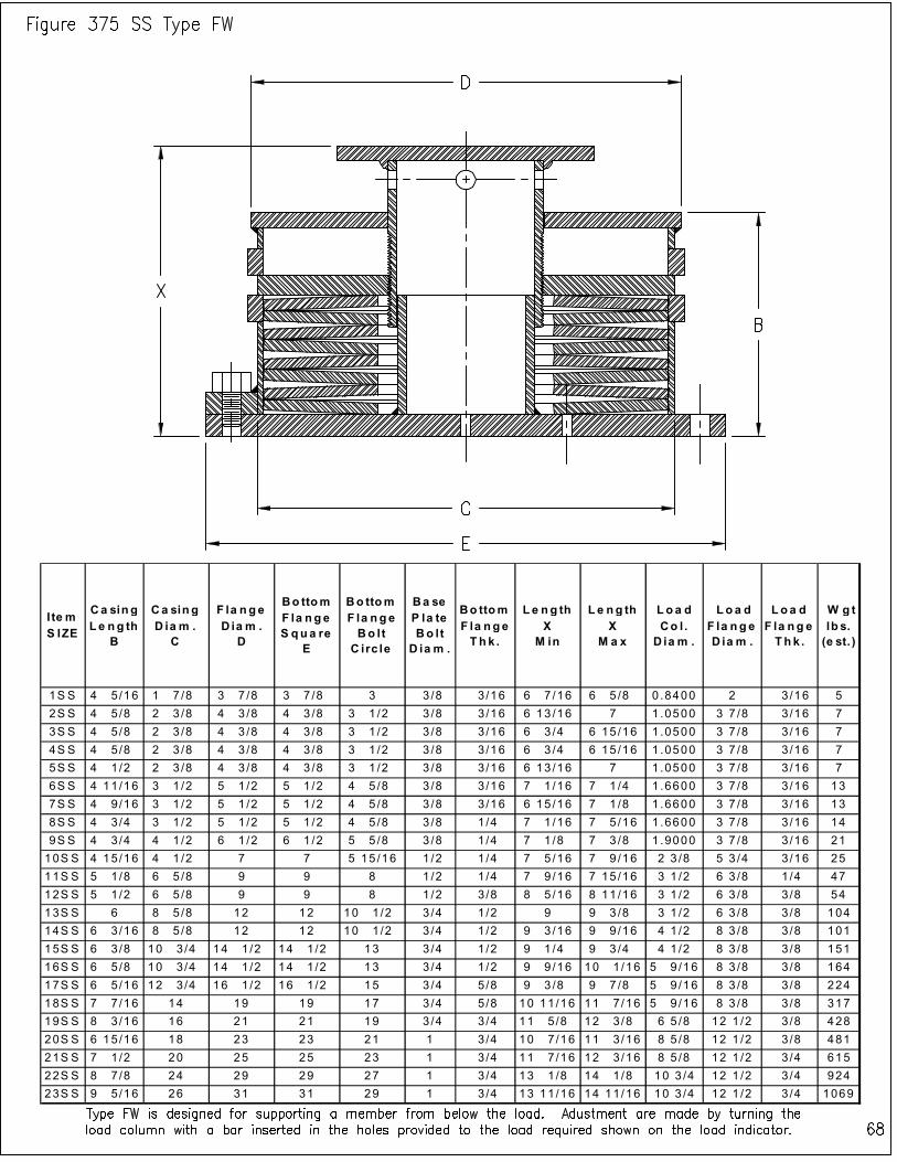
I te m S IZE
Ca sing L e ng th
B
Ca sing D ia m .
C
F la nge D ia m .
D
Bo ttom F la nge S qua re
E
Bo ttom F la nge Bo lt
C irc le
Ba se P la te Bo lt
D ia m .
Bo ttom F la nge Th k .
L e ng th X
M in
L e ng th X
M a x
Loa d Co l .
D ia m .
L o a d F la nge D ia m .
Loa d F la ng e Th k .
W g t lb s. (e st. )
1S S 4 5 /16 1 7 /8 3 7 /8 3 7 /8 3 3 /8 3/16 6 7 /16 6 5 /8 0 .8400 2 3/16 5
2S S 4 5 /8 2 3 /8 4 3 /8 4 3 /8 3 1 /2 3 /8 3/16 6 13 /16 7 1 .0500 3 7 /8 3 /16 7
3S S 4 5 /8 2 3 /8 4 3 /8 4 3 /8 3 1 /2 3 /8 3/16 6 3 /4 6 15 /16 1 .0500 3 7 /8 3 /16 7
4S S 4 5 /8 2 3 /8 4 3 /8 4 3 /8 3 1 /2 3 /8 3/16 6 3 /4 6 15 /16 1 .0500 3 7 /8 3 /16 7
5S S 4 1 /2 2 3 /8 4 3 /8 4 3 /8 3 1 /2 3 /8 3/16 6 13 /16 7 1 .0500 3 7 /8 3 /16 7
6S S 4 11/16 3 1 /2 5 1 /2 5 1 /2 4 5 /8 3 /8 3/16 7 1 /16 7 1 /4 1 .6600 3 7 /8 3 /16 13
7S S 4 9 /16 3 1 /2 5 1 /2 5 1 /2 4 5 /8 3 /8 3/16 6 15 /16 7 1 /8 1 .6600 3 7 /8 3 /16 13
8S S 4 3 /4 3 1 /2 5 1 /2 5 1 /2 4 5 /8 3 /8 1/4 7 1 /16 7 5 /16 1 .6600 3 7 /8 3 /16 14
9S S 4 3 /4 4 1 /2 6 1 /2 6 1 /2 5 5 /8 3 /8 1/4 7 1 /8 7 3 /8 1 .9000 3 7 /8 3 /16 21
10S S 4 15/16 4 1 /2 7 7 5 15 /16 1 /2 1/4 7 5 /16 7 9 /16 2 3 /8 5 3 /4 3 /16 25
11S S 5 1 /8 6 5 /8 9 9 8 1 /2 1/4 7 9 /16 7 15 /16 3 1 /2 6 3 /8 1 /4 47
12S S 5 1 /2 6 5 /8 9 9 8 1 /2 3/8 8 5 /16 8 11 /16 3 1 /2 6 3 /8 3 /8 54
13S S 6 8 5 /8 12 12 10 1 /2 3 /4 1/2 9 9 3 /8 3 1 /2 6 3 /8 3 /8 104
14S S 6 3 /16 8 5 /8 12 12 10 1 /2 3 /4 1/2 9 3 /16 9 9 /16 4 1 /2 8 3 /8 3 /8 101
15S S 6 3 /8 10 3 /4 14 1 /2 14 1 /2 13 3 /4 1/2 9 1 /4 9 3 /4 4 1 /2 8 3 /8 3 /8 151
16S S 6 5 /8 10 3 /4 14 1 /2 14 1 /2 13 3 /4 1/2 9 9 /16 10 1 /16 5 9 /16 8 3 /8 3 /8 164
17S S 6 5 /16 12 3 /4 16 1 /2 16 1 /2 15 3 /4 5/8 9 3 /8 9 7 /8 5 9 /16 8 3 /8 3 /8 224
18S S 7 7 /16 14 19 19 17 3 /4 5/8 10 11/16 11 7 /16 5 9 /16 8 3 /8 3 /8 317
19S S 8 3 /16 16 21 21 19 3 /4 3/4 11 5 /8 12 3 /8 6 5 /8 12 1 /2 3 /8 428
20S S 6 15/16 18 23 23 21 1 3/4 10 7 /16 11 3 /16 8 5 /8 12 1 /2 3 /8 481
21S S 7 1 /2 20 25 25 23 1 3/4 11 7 /16 12 3 /16 8 5 /8 12 1 /2 3 /4 615
22S S 8 7 /8 24 29 29 27 1 3/4 13 1 /8 14 1 /8 10 3 /4 12 1 /2 3 /4 924
23S S 9 5 /16 26 31 31 29 1 3/4 13 11/16 14 11/16 10 3 /4 12 1 /2 3 /4 1069

Item S IZE
Rod Diam .
A
Casing Le ngth
B
Casing Dia m .
C
Flange Diam .
E
Le ngth X
M in
Length X
M a x
W gt lbs.
(e st.)
1SS 1/2 4 5/16 1 7/8 3 7/8 6 7/16 6 5/8 5
2SS 1/2 4 5/8 2 3/8 4 3/8 6 13/16 7 7
3SS 1/2 4 5/8 2 3/8 4 3/8 6 3/4 6 15/16 7
4SS 1/2 4 5/8 2 3/8 4 3/8 6 3/4 6 15/16 7
5SS 1/2 4 1/2 2 3/8 4 3/8 6 13/16 7 7
6SS 1/2 4 3/4 3 1/2 5 1/2 7 3/16 7 3/8 12
7SS 5/8 4 5/8 3 1/2 5 1/2 7 1/16 7 1/4 12
8SS 5/8 4 13/16 3 1/2 5 1/2 7 3/16 7 7/16 13
9SS 3/4 4 15/16 4 1/2 6 1/2 7 1/2 7 3/4 20
10SS 3/4 5 3/16 4 1/2 7 7 13/16 8 1/16 24
11SS 3/4 5 1/2 6 5/8 9 8 7/16 8 13/16 47
12SS 1 5 3/4 6 5/8 9 8 15/16 9 5/16 50
13SS 1 6 1/4 8 5/8 12 9 5/8 10 102
14SS 1 1/4 6 9/16 8 5/8 12 9 15/16 10 5/16 105
15SS 1 1/4 6 3/4 10 3/4 14 1/2 10 1/4 10 3/4 167
16SS 1 1/4 7 3/8 10 3/4 14 1/2 11 3/16 11 11/16 183
17SS 1 1/2 7 3/16 12 3/4 16 1/2 11 11 1/2 261
18SS 2 8 7/16 14 19 12 9/16 13 5/16 381
19SS 2 1/4 9 5/16 16 21 14 1/4 15 524
20SS 2 3/4 8 7/16 18 23 13 13/16 14 9/16 640
21SS 2 3/4 9 20 25 14 9/16 15 5/16 797
22SS 3 10 3/4 24 29 16 7/8 17 7/8 1224
23SS 3 11 9/16 26 31 18 1/16 19 1/16 1501

I te m S IZE
Rod D ia m .
A
Ca sin g L e n g th
B
Ca sin g D ia m .
D
F la n ge D ia m .
E
L e ng th X
M in
L e n g th X
M a x
Lug Th k .
T
Lug ra d iu s
R
P in h e ig h t
H
Lu g Ho le D ia m e te r
F
W g t lb s.
(e st. )
1S S 1 /2 4 5 /16 1 7 /8 3 7 /8 6 7 /16 6 5 /8 1 /4 1 1 /4 1 1 /2 11/16 5
2S S 1 /2 4 5 /8 2 3 /8 4 3 /8 6 13 /16 7 1 /4 1 1 /4 1 1 /2 11/16 7
3S S 1 /2 4 5 /8 2 3 /8 4 3 /8 6 3 /4 6 15/16 1 /4 1 1 /4 1 1 /2 11/16 7
4S S 1 /2 4 5 /8 2 3 /8 4 3 /8 6 3 /4 6 15/16 1 /4 1 1 /4 1 1 /2 11/16 7
5S S 1 /2 4 1 /2 2 3 /8 4 3 /8 6 13 /16 7 1 /4 1 1 /4 1 1 /2 11/16 7
6S S 1 /2 4 3 /4 3 1 /2 5 1 /2 7 3 /16 7 3 /8 1 /4 1 1 /4 1 1 /2 11/16 12
7S S 5 /8 4 5 /8 3 1 /2 5 1 /2 7 1 /16 7 1 /4 1 /4 1 1 /4 1 1 /2 13/16 12
8S S 5 /8 4 13/16 3 1 /2 5 1 /2 7 3 /16 7 7 /16 1 /4 1 1 /4 1 1 /2 13/16 13
9S S 3 /4 4 15/16 4 1 /2 6 1 /2 7 1 /2 7 3 /4 3 /8 1 1 /4 1 1 /2 15/16 20
10S S 3 /4 5 3 /16 4 1 /2 7 7 13 /16 8 1 /16 3 /8 1 1 /4 1 1 /2 15/16 24
11S S 3 /4 5 1 /2 6 5 /8 9 8 7 /16 8 13/16 3 /8 1 1 /4 1 1 /2 15/16 47
12S S 1 5 3 /4 6 5 /8 9 8 15 /16 9 5 /16 1 /2 1 1 /2 2 1 1 /4 50
13S S 1 6 1 /4 8 5 /8 12 9 5 /8 10 1 /2 1 1 /2 2 1 1 /4 102
14S S 1 1 /4 6 9 /16 8 5 /8 12 9 15 /16 10 5 /16 5 /8 2 3 1 1 /2 105
15S S 1 1 /4 6 3 /4 10 3 /4 14 1 /2 10 1 /4 10 3 /4 5 /8 2 3 1 1 /2 167
16S S 1 1 /4 7 3 /8 10 3 /4 14 1 /2 11 3 /16 11 11 /16 5 /8 2 3 1 1 /2 183
17S S 1 1 /2 7 3 /16 12 3 /4 16 1 /2 11 11 1 /2 3 /4 2 1 /2 3 1 3 /4 261
18S S 2 8 7 /16 14 19 12 9 /16 13 5 /16 3 /4 3 4 2 3 /8 381
19S S 2 1 /4 9 5 /16 16 21 14 1 /4 15 3 /4 3 4 1 /2 2 5 /8 524
20S S 2 3 /4 8 7 /16 18 23 13 13 /16 14 9 /16 1 4 4 1 /2 3 1 /8 640
21S S 2 3 /4 9 20 25 14 9 /16 15 5 /16 1 4 4 1 /2 3 1 /8 797
22S S 3 10 3 /4 24 29 16 7 /8 17 7 /8 1 4 5 3 3 /8 1224
23S S 3 11 9 /16 26 31 18 1 /16 19 1 /16 1 4 5 3 3 /8 1501
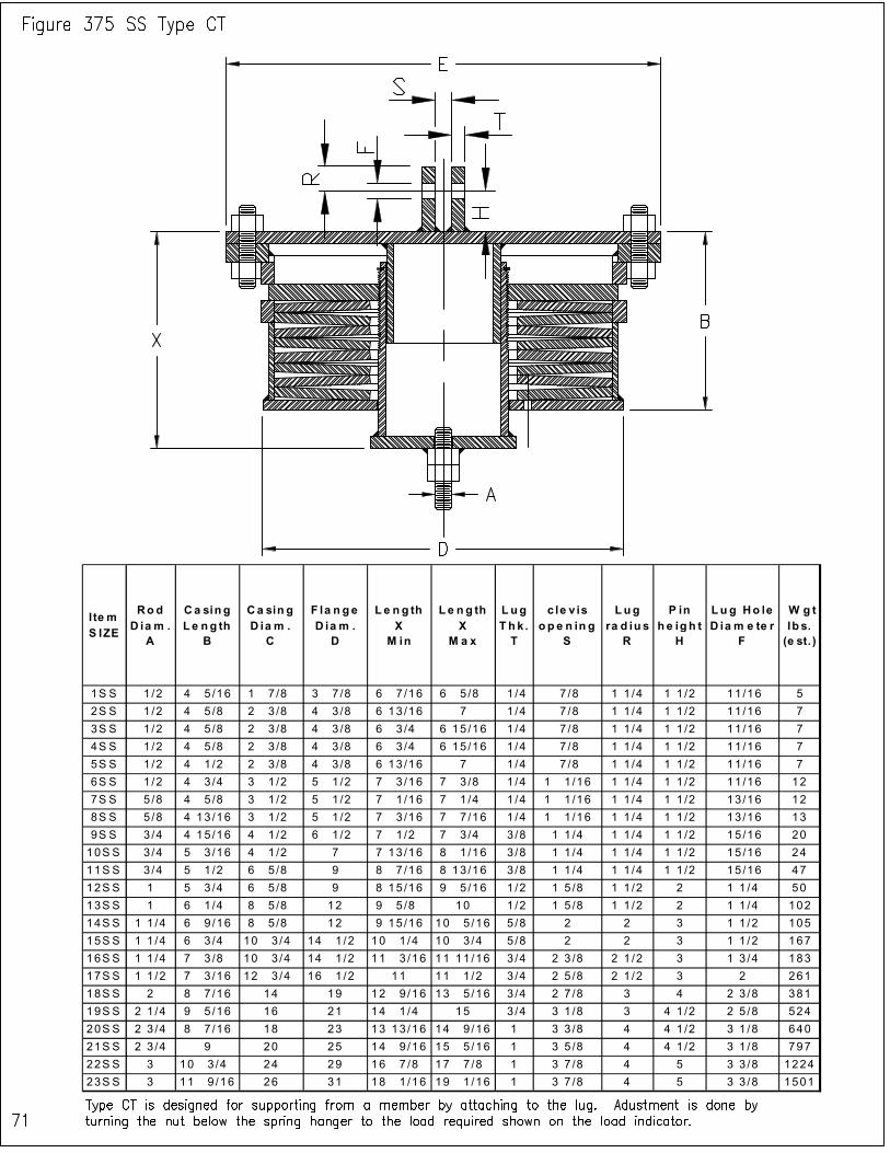
I te m S IZE
Rod D ia m .
A
Ca sing L e ng th
B
Ca sin g D ia m .
C
F la n ge D ia m .
D
L e n g th X
M in
Le n g th X
M a x
L ug T hk . T
c le v is o p e n in g
S
Lug ra d iu s
R
P in h e igh t
H
Lu g Ho le D ia m e te r
F
W g t lb s. (e st. )
1S S 1/2 4 5 /16 1 7 /8 3 7 /8 6 7 /16 6 5 /8 1 /4 7 /8 1 1 /4 1 1 /2 11 /16 5
2S S 1/2 4 5 /8 2 3 /8 4 3 /8 6 13 /16 7 1 /4 7 /8 1 1 /4 1 1 /2 11 /16 7
3S S 1/2 4 5 /8 2 3 /8 4 3 /8 6 3 /4 6 15 /16 1 /4 7 /8 1 1 /4 1 1 /2 11 /16 7
4S S 1/2 4 5 /8 2 3 /8 4 3 /8 6 3 /4 6 15 /16 1 /4 7 /8 1 1 /4 1 1 /2 11 /16 7
5S S 1/2 4 1 /2 2 3 /8 4 3 /8 6 13 /16 7 1 /4 7 /8 1 1 /4 1 1 /2 11 /16 7
6S S 1/2 4 3 /4 3 1 /2 5 1 /2 7 3 /16 7 3 /8 1 /4 1 1 /16 1 1 /4 1 1 /2 11 /16 12
7S S 5/8 4 5 /8 3 1 /2 5 1 /2 7 1 /16 7 1 /4 1 /4 1 1 /16 1 1 /4 1 1 /2 13 /16 12
8S S 5/8 4 13 /16 3 1 /2 5 1 /2 7 3 /16 7 7 /16 1 /4 1 1 /16 1 1 /4 1 1 /2 13 /16 13
9S S 3/4 4 15 /16 4 1 /2 6 1 /2 7 1 /2 7 3 /4 3 /8 1 1 /4 1 1 /4 1 1 /2 15 /16 20
10S S 3/4 5 3 /16 4 1 /2 7 7 13 /16 8 1 /16 3 /8 1 1 /4 1 1 /4 1 1 /2 15 /16 24
11S S 3/4 5 1 /2 6 5 /8 9 8 7 /16 8 13 /16 3 /8 1 1 /4 1 1 /4 1 1 /2 15 /16 47
12S S 1 5 3 /4 6 5 /8 9 8 15 /16 9 5 /16 1 /2 1 5 /8 1 1 /2 2 1 1 /4 50
13S S 1 6 1 /4 8 5 /8 12 9 5 /8 10 1 /2 1 5 /8 1 1 /2 2 1 1 /4 102
14S S 1 1 /4 6 9 /16 8 5 /8 12 9 15 /16 10 5 /16 5 /8 2 2 3 1 1 /2 105
15S S 1 1 /4 6 3 /4 10 3 /4 14 1 /2 10 1 /4 10 3 /4 5 /8 2 2 3 1 1 /2 167
16S S 1 1 /4 7 3 /8 10 3 /4 14 1 /2 11 3 /16 11 11 /16 3 /4 2 3 /8 2 1 /2 3 1 3 /4 183
17S S 1 1 /2 7 3 /16 12 3 /4 16 1 /2 11 11 1 /2 3 /4 2 5 /8 2 1 /2 3 2 261
18S S 2 8 7 /16 14 19 12 9 /16 13 5 /16 3 /4 2 7 /8 3 4 2 3 /8 381
19S S 2 1 /4 9 5 /16 16 21 14 1 /4 15 3 /4 3 1 /8 3 4 1 /2 2 5 /8 524
20S S 2 3 /4 8 7 /16 18 23 13 13 /16 14 9 /16 1 3 3 /8 4 4 1 /2 3 1 /8 640
21S S 2 3 /4 9 20 25 14 9 /16 15 5 /16 1 3 5 /8 4 4 1 /2 3 1 /8 797
22S S 3 10 3 /4 24 29 16 7 /8 17 7 /8 1 3 7 /8 4 5 3 3 /8 1224
23S S 3 11 9 /16 26 31 18 1 /16 19 1 /16 1 3 7 /8 4 5 3 3 /8 1501
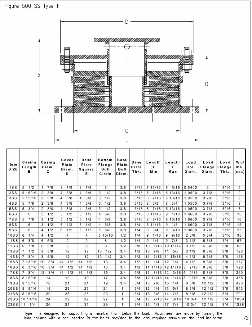
I te m S IZE
Ca sing L e ng th
B
Ca sing D ia m . C
Cove r P la te D ia m . D
Ba se P la te S qua re
E
Bo ttom F la nge Bo lt C irc le
Ba se P la te Bo lt D ia m .
Ba se P la te Thk.
L e ng th X M in
L e ng th X
M a x
Lo a d Co l . D ia m .
Loa d F la nge D ia m .
Lo a d F la nge Thk .
W g t lb s. (e st. )
1S S 5 1 /2 1 7 /8 3 7 /8 3 7 /8 3 3/8 3/16 7 15/16 8 5 /16 0.8400 2 3/16 5
2S S 5 15/16 2 3 /8 4 3 /8 4 3 /8 3 1 /2 3 /8 3/16 8 7 /16 8 13 /16 1.0500 3 7 /8 3 /16 9
3S S 5 15/16 2 3 /8 4 3 /8 4 3 /8 3 1 /2 3 /8 3/16 8 7 /16 8 13 /16 1.0500 3 7 /8 3 /16 9
4S S 5 7 /8 2 3 /8 4 3 /8 4 3 /8 3 1 /2 3 /8 3/16 8 3 /8 8 3 /4 1 .0500 3 7 /8 3 /16 9
5S S 5 3 /4 2 3 /8 4 3 /8 4 3 /8 3 1 /2 3 /8 3/16 8 7 /16 8 13 /16 1.0500 3 7 /8 3 /16 8
6S S 6 3 1 /2 5 1 /2 5 1 /2 4 5 /8 3 /8 3/16 8 11/16 9 1 /16 1.6600 3 7 /8 3 /16 16
7S S 5 7 /8 3 1 /2 5 1 /2 5 1 /2 4 5 /8 3 /8 3/16 8 9 /16 8 15 /16 1.6600 3 7 /8 3 /16 16
8S S 6 3 1 /2 5 1 /2 5 1 /2 4 5 /8 3 /8 1/4 8 11/16 9 1 /8 1 .6600 3 7 /8 3 /16 16
9S S 6 4 1 /2 6 1 /2 6 1 /2 5 5 /8 3 /8 1/4 8 3 /4 9 3 /16 1.9000 3 7 /8 3 /16 25
10S S 6 1 /4 4 1 /2 7 7 5 15/16 1/2 1/4 9 1 /16 9 9 /16 2 3 /8 5 3 /4 3 /16 30
11S S 6 3 /8 6 5 /8 9 9 8 1/2 1/4 9 1 /4 9 7 /8 3 1 /2 6 3 /8 1 /4 57
12S S 6 7 /8 6 5 /8 9 9 8 1/2 3/8 10 1 /16 10 11/16 3 1 /2 6 3 /8 3 /8 65
13S S 7 1 /2 8 5 /8 12 12 10 1 /2 3 /4 1/2 10 7 /8 11 5 /8 3 1 /2 6 3 /8 3 /8 123
14S S 7 3 /4 8 5 /8 12 12 10 1 /2 3 /4 1/2 11 3 /16 11 15/16 4 1 /2 8 3 /8 3 /8 118
15S S 7 13/16 10 3 /4 14 1 /2 14 1 /2 13 3/4 1/2 11 1 /4 12 1 /4 4 1 /2 8 3 /8 3 /8 177
16S S 8 3 /16 10 3 /4 14 1 /2 14 1 /2 13 3/4 1/2 11 11 /16 12 11/16 5 9 /16 8 3 /8 3 /8 193
17S S 7 3 /4 12 3 /4 16 1 /2 16 1 /2 15 3/4 5/8 11 3 /16 12 3 /16 5 9 /16 8 3 /8 3 /8 260
18S S 8 15/16 14 19 19 17 3/4 5/8 12 11 /16 14 1 /16 5 9 /16 8 3 /8 3 /8 365
19S S 9 15/16 16 21 21 19 3/4 3/4 13 7 /8 15 1 /4 6 5 /8 12 1 /2 3 /8 493
20S S 8 5 /16 18 23 23 21 1 3/4 12 1 /8 13 5 /8 8 5 /8 12 1 /2 3 /8 543
21S S 8 15/16 20 25 25 23 1 3/4 13 3 /8 14 7 /8 8 5 /8 12 1 /2 3 /4 701
22S S 10 11/16 24 29 29 27 1 3/4 15 7 /16 17 3 /16 10 3 /4 12 1 /2 3 /4 1068
23S S 11 1 /4 26 31 31 29 1 3/4 16 1 /8 17 7 /8 10 3 /4 12 1 /2 3 /4 1238

I te m S IZE
Ca sing Le ng th
B
Ca sing D ia m .
C
F la nge D iam .
D
Bo ttom F la nge S qua re
E
Bo ttom F la nge Bo lt
C irc le
Ba se P la te Bo lt
D ia m .
Bo ttom F la nge Thk.
Le ng th X
M in
Le ng th X
M a x
Loa d Co l .
D ia m .
Lo a d F la nge D iam .
Loa d F la nge Thk.
W g t lb s. (e st. )
1S S 5 1 /2 1 7 /8 3 7 /8 3 7 /8 3 3/8 3/16 7 15/16 8 1 /8 0.8400 2 3/16 5
2S S 5 15/16 2 3 /8 4 3 /8 4 3 /8 3 1/2 3/8 3/16 8 7 /16 8 5 /8 1.0500 3 7 /8 3/16 9
3S S 5 15/16 2 3 /8 4 3 /8 4 3 /8 3 1/2 3/8 3/16 8 7 /16 8 5 /8 1.0500 3 7 /8 3/16 9
4S S 5 7 /8 2 3 /8 4 3 /8 4 3 /8 3 1/2 3/8 3/16 8 3 /8 8 9 /16 1.0500 3 7 /8 3/16 9
5S S 5 3 /4 2 3 /8 4 3 /8 4 3 /8 3 1/2 3/8 3/16 8 7 /16 8 5 /8 1.0500 3 7 /8 3/16 8
6S S 6 3 1 /2 5 1 /2 5 1 /2 4 5/8 3/8 3/16 8 11/16 8 7 /8 1.6600 3 7 /8 3/16 16
7S S 5 7 /8 3 1 /2 5 1 /2 5 1 /2 4 5/8 3/8 3/16 8 9 /16 8 3 /4 1.6600 3 7 /8 3/16 15
8S S 6 3 1 /2 5 1 /2 5 1 /2 4 5/8 3/8 1/4 8 11/16 8 15/16 1.6600 3 7 /8 3/16 16
9S S 6 4 1 /2 6 1 /2 6 1 /2 5 5/8 3/8 1/4 8 3 /4 9 1.9000 3 7 /8 3/16 25
10S S 6 1 /4 4 1 /2 7 7 5 15/16 1/2 1/4 9 9 1 /4 2 3 /8 5 3 /4 3/16 30
11S S 6 3 /8 6 5 /8 9 9 8 1/2 1/4 9 3 /16 9 9 /16 3 1 /2 6 3 /8 1/4 57
12S S 6 7 /8 6 5 /8 9 9 8 1/2 3/8 10 1 /16 10 7 /16 3 1 /2 6 3 /8 3/8 65
13S S 7 1 /2 8 5 /8 12 12 10 1 /2 3/4 1/2 10 7 /8 11 1 /4 3 1 /2 6 3 /8 3/8 123
14S S 7 3 /4 8 5 /8 12 12 10 1 /2 3/4 1/2 11 3 /16 11 9 /16 4 1 /2 8 3 /8 3/8 118
15S S 7 13/16 10 3 /4 14 1 /2 14 1 /2 13 3/4 1/2 11 1 /8 11 5 /8 4 1 /2 8 3 /8 3/8 176
16S S 8 3 /16 10 3 /4 14 1 /2 14 1 /2 13 3/4 1/2 11 9 /16 12 1 /16 5 9 /16 8 3 /8 3/8 193
17S S 7 3 /4 12 3 /4 16 1 /2 16 1 /2 15 3/4 5/8 11 3 /16 11 11/16 5 9 /16 8 3 /8 3/8 259
18S S 8 15/16 14 19 19 17 3/4 5/8 12 11/16 13 7 /16 5 9 /16 8 3 /8 3/8 364
19S S 9 15/16 16 21 21 19 3/4 3/4 13 7 /8 14 5 /8 6 5 /8 12 1 /2 3/8 492
20S S 8 5 /16 18 23 23 21 1 3/4 12 1 /8 12 7 /8 8 5 /8 12 1 /2 3/8 541
21S S 8 15/16 20 25 25 23 1 3/4 13 3 /8 14 1 /8 8 5 /8 12 1 /2 3/4 699
22S S 10 11/16 24 29 29 27 1 3/4 15 7 /16 16 7 /16 10 3 /4 12 1 /2 3 /4 1065
23S S 11 1 /4 26 31 31 29 1 3/4 16 1 /8 17 1 /8 10 3 /4 12 1 /2 3/4 1235
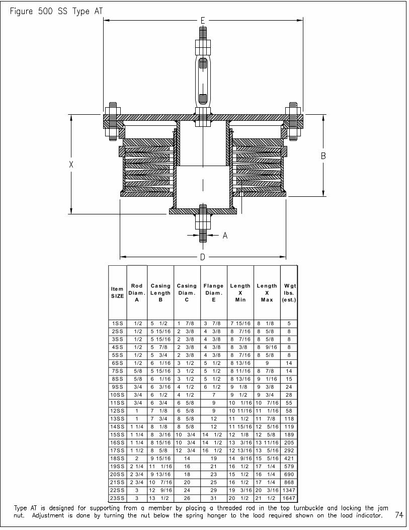
Item S IZE
Rod Diam .
A
Casing Le ngth
B
Casing Dia m .
C
Flange Diam .
E
Le ngth X
M in
Length X
Ma x
W gt lbs.
(e st.)
1SS 1/2 5 1/2 1 7/8 3 7/8 7 15/16 8 1/8 5
2SS 1/2 5 15/16 2 3/8 4 3/8 8 7/16 8 5/8 8
3SS 1/2 5 15/16 2 3/8 4 3/8 8 7/16 8 5/8 8
4SS 1/2 5 7/8 2 3/8 4 3/8 8 3/8 8 9/16 8
5SS 1/2 5 3/4 2 3/8 4 3/8 8 7/16 8 5/8 8
6SS 1/2 6 1/16 3 1/2 5 1/2 8 13/16 9 14
7SS 5/8 5 15/16 3 1/2 5 1/2 8 11/16 8 7/8 14
8SS 5/8 6 1/16 3 1/2 5 1/2 8 13/16 9 1/16 15
9SS 3/4 6 3/16 4 1/2 6 1/2 9 1/8 9 3/8 24
10SS 3/4 6 1/2 4 1/2 7 9 1/2 9 3/4 28
11SS 3/4 6 3/4 6 5/8 9 10 1/16 10 7/16 55
12SS 1 7 1/8 6 5/8 9 10 11/16 11 1/16 58
13SS 1 7 3/4 8 5/8 12 11 1/2 11 7/8 118
14SS 1 1/4 8 1/8 8 5/8 12 11 15/16 12 5/16 119
15SS 1 1/4 8 3/16 10 3/4 14 1/2 12 1/8 12 5/8 189
16SS 1 1/4 8 15/16 10 3/4 14 1/2 13 3/16 13 11/16 205
17SS 1 1/2 8 5/8 12 3/4 16 1/2 12 13/16 13 5/16 292
18SS 2 9 15/16 14 19 14 9/16 15 5/16 421
19SS 2 1/4 11 1/16 16 21 16 1/2 17 1/4 579
20SS 2 3/4 9 13/16 18 23 15 1/2 16 1/4 690
21SS 2 3/4 10 7/16 20 25 16 1/2 17 1/4 868
22SS 3 12 9/16 24 29 19 3/16 20 3/16 1347
23SS 3 13 1/2 26 31 20 1/2 21 1/2 1647
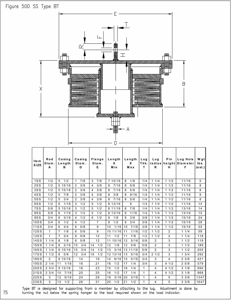
I te m S IZE
Rod D ia m .
A
Ca sin g L e ng th
B
Ca sin g D ia m .
D
F la ng e D ia m .
E
L e ng th X
M in
L e ng th X
M a x
Lug Th k .
T
Lu g ra d iu s
R
P in h e ig h t
H
Lug Ho le D ia m e te r
F
W g t lb s. (e st. )
1S S 1 /2 5 1 /2 1 7 /8 3 7 /8 7 15 /16 8 1 /8 1/4 1 1 /4 1 1 /2 11 /16 5
2S S 1 /2 5 15 /16 2 3 /8 4 3 /8 8 7 /16 8 5 /8 1/4 1 1 /4 1 1 /2 11 /16 8
3S S 1 /2 5 15 /16 2 3 /8 4 3 /8 8 7 /16 8 5 /8 1/4 1 1 /4 1 1 /2 11 /16 8
4S S 1 /2 5 7 /8 2 3 /8 4 3 /8 8 3 /8 8 9 /16 1/4 1 1 /4 1 1 /2 11 /16 8
5S S 1 /2 5 3 /4 2 3 /8 4 3 /8 8 7 /16 8 5 /8 1/4 1 1 /4 1 1 /2 11 /16 8
6S S 1 /2 6 1 /16 3 1 /2 5 1 /2 8 13 /16 9 1/4 1 1 /4 1 1 /2 11 /16 14
7S S 5 /8 5 15 /16 3 1 /2 5 1 /2 8 11 /16 8 7 /8 1/4 1 1 /4 1 1 /2 13 /16 14
8S S 5 /8 6 1 /16 3 1 /2 5 1 /2 8 13 /16 9 1 /16 1/4 1 1 /4 1 1 /2 13 /16 15
9S S 3 /4 6 3 /16 4 1 /2 6 1 /2 9 1 /8 9 3 /8 3/8 1 1 /4 1 1 /2 15 /16 24
10S S 3 /4 6 1 /2 4 1 /2 7 9 1 /2 9 3 /4 3/8 1 1 /4 1 1 /2 15 /16 28
11S S 3 /4 6 3 /4 6 5 /8 9 10 1 /16 10 7 /16 3/8 1 1 /4 1 1 /2 15 /16 55
12S S 1 7 1 /8 6 5 /8 9 10 11 /16 11 1 /16 1/2 1 1 /2 2 1 1 /4 58
13S S 1 7 3 /4 8 5 /8 12 11 1 /2 11 7 /8 1/2 1 1 /2 2 1 1 /4 118
14S S 1 1 /4 8 1 /8 8 5 /8 12 11 15 /16 12 5 /16 5/8 2 3 1 1 /2 119
15S S 1 1 /4 8 3 /16 10 3 /4 14 1 /2 12 1 /8 12 5 /8 5/8 2 3 1 1 /2 189
16S S 1 1 /4 8 15 /16 10 3 /4 14 1 /2 13 3 /16 13 11/16 5/8 2 3 1 1 /2 205
17S S 1 1 /2 8 5 /8 12 3 /4 16 1 /2 12 13 /16 13 5 /16 3/4 2 1 /2 3 1 3 /4 292
18S S 2 9 15 /16 14 19 14 9 /16 15 5 /16 3/4 3 4 2 3 /8 421
19S S 2 1 /4 11 1 /16 16 21 16 1 /2 17 1 /4 3/4 3 4 1 /2 2 5 /8 579
20S S 2 3 /4 9 13 /16 18 23 15 1 /2 16 1 /4 1 4 4 1 /2 3 1 /8 690
21S S 2 3 /4 10 7 /16 20 25 16 1 /2 17 1 /4 1 4 4 1 /2 3 1 /8 868
22S S 3 12 9 /16 24 29 19 3 /16 20 3 /16 1 4 5 3 3 /8 1347
23S S 3 13 1 /2 26 31 20 1 /2 21 1 /2 1 4 5 3 3 /8 1647

I te m S IZE
Rod D ia m .
A
Ca sin g L e ng th
B
Ca sin g D ia m .
C
F la n ge D ia m .
D
L e n g th X
M in
L e n g th X
M a x
L ug T h k . T
c le v is o p e n in g
S
Lug ra d iu s
R
P in h e ig h t
H
Lu g Ho le D ia m e te r
F
W g t lb s. (e st. )
1S S 1 /2 5 1 /2 1 7 /8 3 7 /8 7 15 /16 8 1 /8 1 /4 7 /8 1 1 /4 1 1 /2 11 /16 5
2S S 1 /2 5 15 /16 2 3 /8 4 3 /8 8 7 /16 8 5 /8 1 /4 7 /8 1 1 /4 1 1 /2 11 /16 8
3S S 1 /2 5 15 /16 2 3 /8 4 3 /8 8 7 /16 8 5 /8 1 /4 7 /8 1 1 /4 1 1 /2 11 /16 8
4S S 1 /2 5 7 /8 2 3 /8 4 3 /8 8 3 /8 8 9 /16 1 /4 7 /8 1 1 /4 1 1 /2 11 /16 8
5S S 1 /2 5 3 /4 2 3 /8 4 3 /8 8 7 /16 8 5 /8 1 /4 7 /8 1 1 /4 1 1 /2 11 /16 8
6S S 1 /2 6 1 /16 3 1 /2 5 1 /2 8 13 /16 9 1 /4 1 1 /16 1 1 /4 1 1 /2 11 /16 14
7S S 5 /8 5 15 /16 3 1 /2 5 1 /2 8 11 /16 8 7 /8 1 /4 1 1 /16 1 1 /4 1 1 /2 13 /16 14
8S S 5 /8 6 1 /16 3 1 /2 5 1 /2 8 13 /16 9 1 /16 1 /4 1 1 /16 1 1 /4 1 1 /2 13 /16 15
9S S 3 /4 6 3 /16 4 1 /2 6 1 /2 9 1 /8 9 3 /8 3 /8 1 1 /4 1 1 /4 1 1 /2 15 /16 24
10S S 3 /4 6 1 /2 4 1 /2 7 9 1 /2 9 3 /4 3 /8 1 1 /4 1 1 /4 1 1 /2 15 /16 28
11S S 3 /4 6 3 /4 6 5 /8 9 10 1 /16 10 7 /16 3 /8 1 1 /4 1 1 /4 1 1 /2 15 /16 55
12S S 1 7 1 /8 6 5 /8 9 10 11 /16 11 1 /16 1 /2 1 5 /8 1 1 /2 2 1 1 /4 58
13S S 1 7 3 /4 8 5 /8 12 11 1 /2 11 7 /8 1 /2 1 5 /8 1 1 /2 2 1 1 /4 118
14S S 1 1 /4 8 1 /8 8 5 /8 12 11 15 /16 12 5 /16 5 /8 2 2 3 1 1 /2 119
15S S 1 1 /4 8 3 /16 10 3 /4 14 1 /2 12 1 /8 12 5 /8 5 /8 2 2 3 1 1 /2 189
16S S 1 1 /4 8 15 /16 10 3 /4 14 1 /2 13 3 /16 13 11 /16 3 /4 2 3 /8 2 1 /2 3 1 3 /4 205
17S S 1 1 /2 8 5 /8 12 3 /4 16 1 /2 12 13 /16 13 5 /16 3 /4 2 5 /8 2 1 /2 3 2 292
18S S 2 9 15 /16 14 19 14 9 /16 15 5 /16 3 /4 2 7 /8 3 4 2 3 /8 421
19S S 2 1 /4 11 1 /16 16 21 16 1 /2 17 1 /4 3 /4 3 1 /8 3 4 1 /2 2 5 /8 579
20S S 2 3 /4 9 13 /16 18 23 15 1 /2 16 1 /4 1 3 3 /8 4 4 1 /2 3 1 /8 690
21S S 2 3 /4 10 7 /16 20 25 16 1 /2 17 1 /4 1 3 5 /8 4 4 1 /2 3 1 /8 868
22S S 3 12 9 /16 24 29 19 3 /16 20 3 /16 1 3 7 /8 4 5 3 3 /8 1347
23S S 3 13 1 /2 26 31 20 1 /2 21 1 /2 1 3 7 /8 4 5 3 3 /8 1647
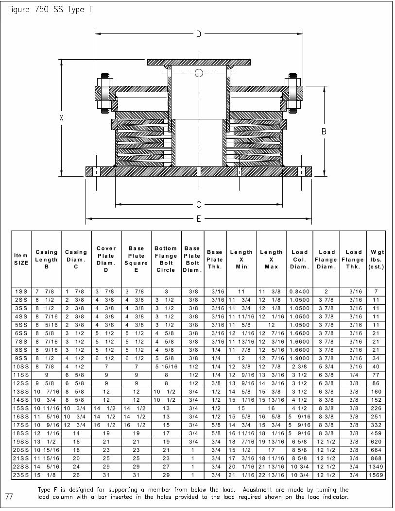
I te m S IZE
Ca sing L e ng th
B
Ca sing D ia m . C
Cove r P la te D ia m . D
Ba se P la te S qu a re
E
Bo ttom F la nge Bo lt C irc le
Ba se P la te Bo lt D ia m .
Ba se P la te Thk .
L e ng th X M in
Le ng th X
M a x
Loa d Co l . D ia m .
L oa d F la nge D ia m .
Lo a d F la n ge Thk .
W g t lb s. (e st. )
1S S 7 7 /8 1 7 /8 3 7 /8 3 7 /8 3 3/8 3 /16 11 11 3 /8 0.8400 2 3/16 7
2S S 8 1 /2 2 3 /8 4 3 /8 4 3 /8 3 1 /2 3/8 3 /16 11 3 /4 12 1 /8 1.0500 3 7 /8 3/16 11
3S S 8 1 /2 2 3 /8 4 3 /8 4 3 /8 3 1 /2 3/8 3 /16 11 3 /4 12 1 /8 1.0500 3 7 /8 3/16 11
4S S 8 7 /16 2 3 /8 4 3 /8 4 3 /8 3 1 /2 3/8 3 /16 11 11/16 12 1 /16 1.0500 3 7 /8 3/16 11
5S S 8 5 /16 2 3 /8 4 3 /8 4 3 /8 3 1 /2 3/8 3 /16 11 5 /8 12 1.0500 3 7 /8 3/16 11
6S S 8 5 /8 3 1 /2 5 1 /2 5 1 /2 4 5 /8 3/8 3 /16 12 1 /16 12 7 /16 1.6600 3 7 /8 3/16 21
7S S 8 7 /16 3 1 /2 5 1 /2 5 1 /2 4 5 /8 3/8 3 /16 11 13/16 12 3 /16 1.6600 3 7 /8 3/16 21
8S S 8 9 /16 3 1 /2 5 1 /2 5 1 /2 4 5 /8 3/8 1 /4 11 7 /8 12 5 /16 1.6600 3 7 /8 3/16 21
9S S 8 1 /2 4 1 /2 6 1 /2 6 1 /2 5 5 /8 3/8 1 /4 12 12 7 /16 1.9000 3 7 /8 3/16 34
10S S 8 7 /8 4 1 /2 7 7 5 15 /16 1/2 1 /4 12 3 /8 12 7 /8 2 3 /8 5 3 /4 3/16 40
11S S 9 6 5 /8 9 9 8 1/2 1 /4 12 9 /16 13 3 /16 3 1 /2 6 3 /8 1/4 77
12S S 9 5 /8 6 5 /8 9 9 8 1/2 3 /8 13 9 /16 14 3 /16 3 1 /2 6 3 /8 3/8 86
13S S 10 7 /16 8 5 /8 12 12 10 1 /2 3/4 1 /2 14 5 /8 15 3 /8 3 1 /2 6 3 /8 3/8 160
14S S 10 3 /4 8 5 /8 12 12 10 1 /2 3/4 1 /2 15 1 /16 15 13 /16 4 1 /2 8 3 /8 3/8 152
15S S 10 11/16 10 3 /4 14 1 /2 14 1 /2 13 3/4 1 /2 15 16 4 1 /2 8 3 /8 3/8 226
16S S 11 5 /16 10 3 /4 14 1 /2 14 1 /2 13 3/4 1 /2 15 5 /8 16 5 /8 5 9 /16 8 3 /8 3/8 251
17S S 10 9 /16 12 3 /4 16 1 /2 16 1 /2 15 3/4 5 /8 14 3 /4 15 3 /4 5 9 /16 8 3 /8 3/8 332
18S S 12 1 /16 14 19 19 17 3/4 5 /8 16 11/16 18 1 /16 5 9 /16 8 3 /8 3/8 459
19S S 13 1 /2 16 21 21 19 3/4 3 /4 18 7 /16 19 13 /16 6 5 /8 12 1 /2 3 /8 620
20S S 10 15/16 18 23 23 21 1 3 /4 15 1 /2 17 8 5 /8 12 1 /2 3/8 664
21S S 11 15/16 20 25 25 23 1 3 /4 17 3 /16 18 11 /16 8 5 /8 12 1 /2 3 /4 868
22S S 14 5 /16 24 29 29 27 1 3 /4 20 1 /16 21 13 /16 10 3 /4 12 1 /2 3 /4 1349
23S S 15 1 /8 26 31 31 29 1 3 /4 21 1 /16 22 13 /16 10 3 /4 12 1 /2 3/4 1569
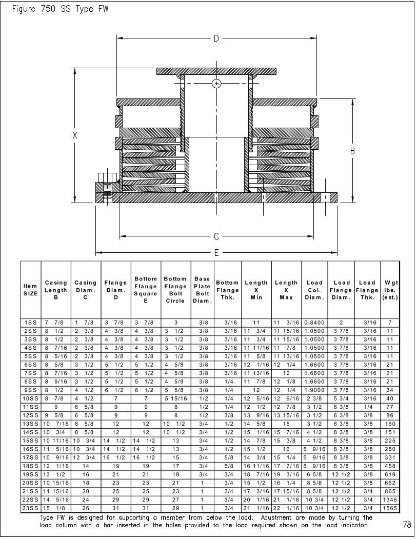
I te m S IZE
Ca sing Le ng th
B
Ca sing D ia m .
C
F la nge D iam .
D
Bo ttom F la nge S qua re
E
Bo ttom F la nge Bo lt
C irc le
Ba se P la te Bo lt
D ia m .
Bo ttom F la nge Thk.
L e ng th X
M in
Le ng th X
M a x
Loa d Co l.
D ia m .
L oa d F la nge D ia m .
Loa d F la nge Thk.
W g t lbs. (e st. )
1S S 7 7 /8 1 7 /8 3 7 /8 3 7 /8 3 3/8 3/16 11 11 3 /16 0.8400 2 3/16 7
2S S 8 1 /2 2 3 /8 4 3 /8 4 3 /8 3 1 /2 3/8 3/16 11 3 /4 11 15/16 1.0500 3 7 /8 3/16 11
3S S 8 1 /2 2 3 /8 4 3 /8 4 3 /8 3 1 /2 3/8 3/16 11 3 /4 11 15/16 1.0500 3 7 /8 3/16 11
4S S 8 7 /16 2 3 /8 4 3 /8 4 3 /8 3 1 /2 3/8 3/16 11 11/16 11 7 /8 1 .0500 3 7 /8 3/16 11
5S S 8 5 /16 2 3 /8 4 3 /8 4 3 /8 3 1 /2 3/8 3/16 11 5 /8 11 13/16 1.0500 3 7 /8 3/16 11
6S S 8 5 /8 3 1 /2 5 1 /2 5 1 /2 4 5 /8 3/8 3/16 12 1 /16 12 1 /4 1.6600 3 7 /8 3/16 21
7S S 8 7 /16 3 1 /2 5 1 /2 5 1 /2 4 5 /8 3/8 3/16 11 13/16 12 1.6600 3 7 /8 3/16 21
8S S 8 9 /16 3 1 /2 5 1 /2 5 1 /2 4 5 /8 3/8 1/4 11 7 /8 12 1 /8 1.6600 3 7 /8 3/16 21
9S S 8 1 /2 4 1 /2 6 1 /2 6 1 /2 5 5 /8 3/8 1/4 12 12 1 /4 1.9000 3 7 /8 3/16 34
10S S 8 7 /8 4 1 /2 7 7 5 15/16 1/2 1/4 12 5 /16 12 9 /16 2 3 /8 5 3 /4 3/16 40
11S S 9 6 5 /8 9 9 8 1/2 1/4 12 1 /2 12 7 /8 3 1 /2 6 3 /8 1/4 77
12S S 9 5 /8 6 5 /8 9 9 8 1/2 3/8 13 9 /16 13 15/16 3 1 /2 6 3 /8 3/8 86
13S S 10 7 /16 8 5 /8 12 12 10 1 /2 3/4 1/2 14 5 /8 15 3 1 /2 6 3 /8 3 /8 160
14S S 10 3 /4 8 5 /8 12 12 10 1 /2 3/4 1/2 15 1 /16 15 7 /16 4 1 /2 8 3 /8 3/8 151
15S S 10 11/16 10 3 /4 14 1 /2 14 1 /2 13 3/4 1/2 14 7 /8 15 3 /8 4 1 /2 8 3 /8 3/8 225
16S S 11 5 /16 10 3 /4 14 1 /2 14 1 /2 13 3/4 1/2 15 1 /2 16 5 9 /16 8 3 /8 3/8 250
17S S 10 9 /16 12 3 /4 16 1 /2 16 1 /2 15 3/4 5/8 14 3 /4 15 1 /4 5 9 /16 8 3 /8 3/8 331
18S S 12 1 /16 14 19 19 17 3/4 5/8 16 11/16 17 7 /16 5 9 /16 8 3 /8 3/8 458
19S S 13 1 /2 16 21 21 19 3/4 3/4 18 7 /16 19 3 /16 6 5 /8 12 1 /2 3/8 619
20S S 10 15/16 18 23 23 21 1 3/4 15 1 /2 16 1 /4 8 5 /8 12 1 /2 3/8 662
21S S 11 15/16 20 25 25 23 1 3/4 17 3 /16 17 15/16 8 5 /8 12 1 /2 3 /4 865
22S S 14 5 /16 24 29 29 27 1 3/4 20 1 /16 21 1 /16 10 3 /4 12 1 /2 3/4 1346
23S S 15 1 /8 26 31 31 29 1 3/4 21 1 /16 22 1 /16 10 3 /4 12 1 /2 3/4 1565
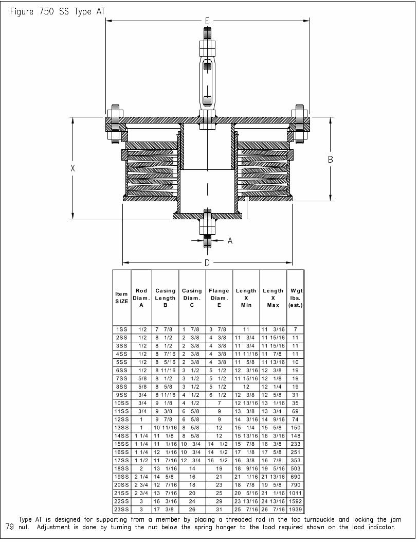
Item S IZE
Rod Diam .
A
Casing Length
B
Casing Diam .
C
Fla nge Diam .
E
Length X
M in
Length X
Max
W gt lbs.
(e st.)
1SS 1/2 7 7/8 1 7/8 3 7/8 11 11 3/16 7
2SS 1/2 8 1/2 2 3/8 4 3/8 11 3/4 11 15/16 11
3SS 1/2 8 1/2 2 3/8 4 3/8 11 3/4 11 15/16 11
4SS 1/2 8 7/16 2 3/8 4 3/8 11 11/16 11 7/8 11
5SS 1/2 8 5/16 2 3/8 4 3/8 11 5/8 11 13/16 10
6SS 1/2 8 11/16 3 1/2 5 1/2 12 3/16 12 3/8 19
7SS 5/8 8 1/2 3 1/2 5 1/2 11 15/16 12 1/8 19
8SS 5/8 8 5/8 3 1/2 5 1/2 12 12 1/4 19
9SS 3/4 8 11/16 4 1/2 6 1/2 12 3/8 12 5/8 31
10SS 3/4 9 1/8 4 1/2 7 12 13/16 13 1/16 35
11SS 3/4 9 3/8 6 5/8 9 13 3/8 13 3/4 69
12SS 1 9 7/8 6 5/8 9 14 3/16 14 9/16 74
13SS 1 10 11/16 8 5/8 12 15 1/4 15 5/8 150
14SS 1 1/4 11 1/8 8 5/8 12 15 13/16 16 3/16 148
15SS 1 1/4 11 1/16 10 3/4 14 1/2 15 7/8 16 3/8 233
16SS 1 1/4 12 1/16 10 3/4 14 1/2 17 1/8 17 5/8 251
17SS 1 1/2 11 7/16 12 3/4 16 1/2 16 3/8 16 7/8 353
18SS 2 13 1/16 14 19 18 9/16 19 5/16 503
19SS 2 1/4 14 5/8 16 21 21 1/16 21 13/16 690
20SS 2 3/4 12 7/16 18 23 18 7/8 19 5/8 790
21SS 2 3/4 13 7/16 20 25 20 5/16 21 1/16 1011
22SS 3 16 3/16 24 29 23 13/16 24 13/16 1592
23SS 3 17 3/8 26 31 25 7/16 26 7/16 1939

I te m S IZE
Rod D ia m .
A
Ca sin g L e n g th
B
Ca sin g D ia m .
D
F la n g e D ia m .
E
L e ng th X
M in
L e n g th X
M a x
Lug T h k .
T
L ug ra d iu s
R
P in h e ig h t
H
Lu g Ho le D ia m e te r
F
W g t lb s.
(e st. )
1S S 1 /2 7 7 /8 1 7 /8 3 7 /8 11 11 3 /16 1 /4 1 1 /4 1 1 /2 11 /16 7
2S S 1 /2 8 1 /2 2 3 /8 4 3 /8 11 3 /4 11 15 /16 1 /4 1 1 /4 1 1 /2 11 /16 11
3S S 1 /2 8 1 /2 2 3 /8 4 3 /8 11 3 /4 11 15 /16 1 /4 1 1 /4 1 1 /2 11 /16 11
4S S 1 /2 8 7 /16 2 3 /8 4 3 /8 11 11 /16 11 7 /8 1 /4 1 1 /4 1 1 /2 11 /16 11
5S S 1 /2 8 5 /16 2 3 /8 4 3 /8 11 5 /8 11 13 /16 1 /4 1 1 /4 1 1 /2 11 /16 10
6S S 1 /2 8 11 /16 3 1 /2 5 1 /2 12 3 /16 12 3 /8 1 /4 1 1 /4 1 1 /2 11 /16 19
7S S 5 /8 8 1 /2 3 1 /2 5 1 /2 11 15 /16 12 1 /8 1 /4 1 1 /4 1 1 /2 13 /16 19
8S S 5 /8 8 5 /8 3 1 /2 5 1 /2 12 12 1 /4 1 /4 1 1 /4 1 1 /2 13 /16 19
9S S 3 /4 8 11 /16 4 1 /2 6 1 /2 12 3 /8 12 5 /8 3 /8 1 1 /4 1 1 /2 15 /16 31
10S S 3 /4 9 1 /8 4 1 /2 7 12 13 /16 13 1 /16 3 /8 1 1 /4 1 1 /2 15 /16 35
11S S 3 /4 9 3 /8 6 5 /8 9 13 3 /8 13 3 /4 3 /8 1 1 /4 1 1 /2 15 /16 69
12S S 1 9 7 /8 6 5 /8 9 14 3 /16 14 9 /16 1 /2 1 1 /2 2 1 1 /4 74
13S S 1 10 11 /16 8 5 /8 12 15 1 /4 15 5 /8 1 /2 1 1 /2 2 1 1 /4 150
14S S 1 1 /4 11 1 /8 8 5 /8 12 15 13 /16 16 3 /16 5 /8 2 3 1 1 /2 148
15S S 1 1 /4 11 1 /16 10 3 /4 14 1 /2 15 7 /8 16 3 /8 5 /8 2 3 1 1 /2 233
16S S 1 1 /4 12 1 /16 10 3 /4 14 1 /2 17 1 /8 17 5 /8 5 /8 2 3 1 1 /2 251
17S S 1 1 /2 11 7 /16 12 3 /4 16 1 /2 16 3 /8 16 7 /8 3 /4 2 1 /2 3 1 3 /4 353
18S S 2 13 1 /16 14 19 18 9 /16 19 5 /16 3 /4 3 4 2 3 /8 503
19S S 2 1 /4 14 5 /8 16 21 21 1 /16 21 13 /16 3 /4 3 4 1 /2 2 5 /8 690
20S S 2 3 /4 12 7 /16 18 23 18 7 /8 19 5 /8 1 4 4 1 /2 3 1 /8 790
21S S 2 3 /4 13 7 /16 20 25 20 5 /16 21 1 /16 1 4 4 1 /2 3 1 /8 1011
22S S 3 16 3 /16 24 29 23 13 /16 24 13 /16 1 4 5 3 3 /8 1592
23S S 3 17 3 /8 26 31 25 7 /16 26 7 /16 1 4 5 3 3 /8 1939
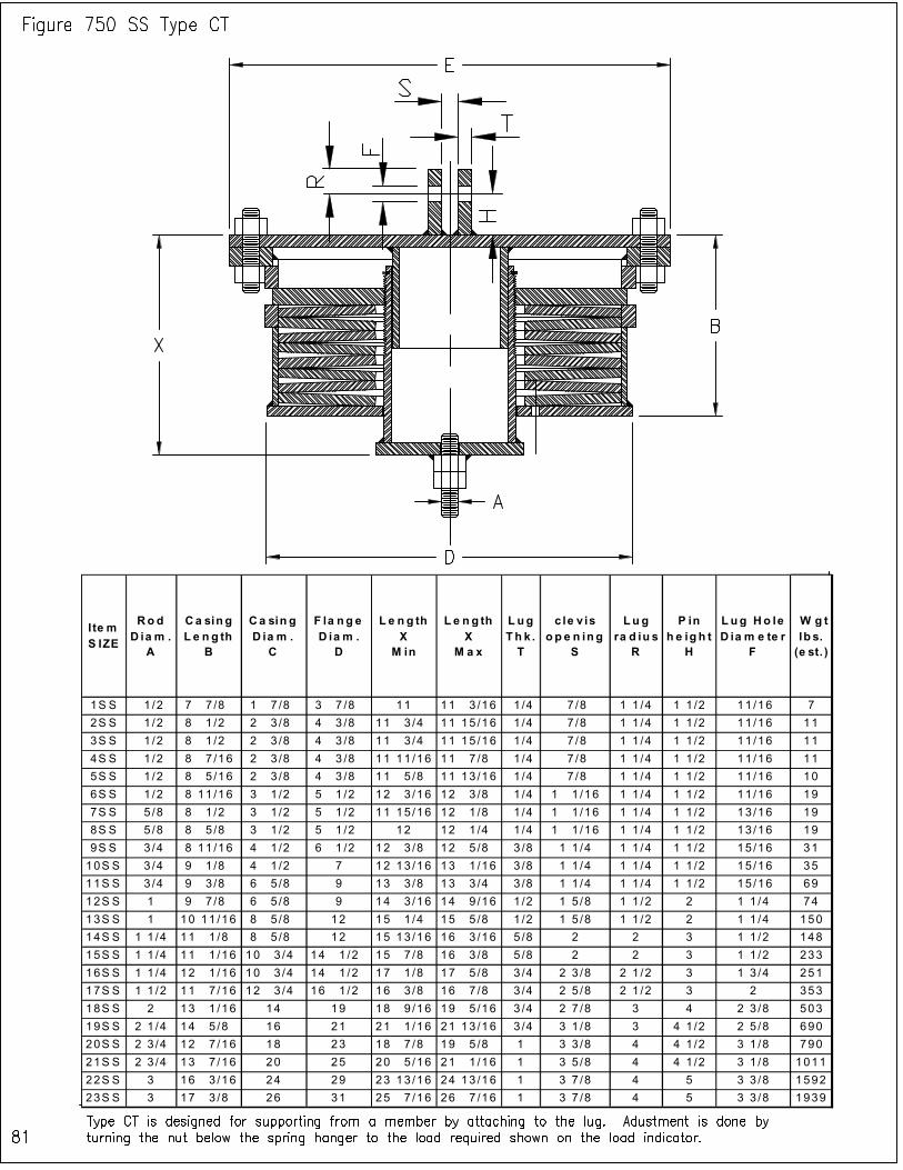
I te m S IZE
Rod D ia m .
A
Ca sin g L e n g th
B
Ca sin g D ia m .
C
F la ng e D ia m .
D
L e n g th X
M in
L e n g th X
M a x
L ug Th k . T
c le v is o p e n in g
S
Lu g ra d iu s
R
P in h e ig h t
H
L ug Ho le D ia m e te r
F
W g t lb s. (e st. )
1S S 1 /2 7 7 /8 1 7 /8 3 7 /8 11 11 3 /16 1 /4 7 /8 1 1 /4 1 1 /2 11 /16 7
2S S 1 /2 8 1 /2 2 3 /8 4 3 /8 11 3 /4 11 15 /16 1 /4 7 /8 1 1 /4 1 1 /2 11 /16 11
3S S 1 /2 8 1 /2 2 3 /8 4 3 /8 11 3 /4 11 15 /16 1 /4 7 /8 1 1 /4 1 1 /2 11 /16 11
4S S 1 /2 8 7 /16 2 3 /8 4 3 /8 11 11 /16 11 7 /8 1 /4 7 /8 1 1 /4 1 1 /2 11 /16 11
5S S 1 /2 8 5 /16 2 3 /8 4 3 /8 11 5 /8 11 13 /16 1 /4 7 /8 1 1 /4 1 1 /2 11 /16 10
6S S 1 /2 8 11 /16 3 1 /2 5 1 /2 12 3 /16 12 3 /8 1 /4 1 1 /16 1 1 /4 1 1 /2 11 /16 19
7S S 5 /8 8 1 /2 3 1 /2 5 1 /2 11 15 /16 12 1 /8 1 /4 1 1 /16 1 1 /4 1 1 /2 13 /16 19
8S S 5 /8 8 5 /8 3 1 /2 5 1 /2 12 12 1 /4 1 /4 1 1 /16 1 1 /4 1 1 /2 13 /16 19
9S S 3 /4 8 11 /16 4 1 /2 6 1 /2 12 3 /8 12 5 /8 3 /8 1 1 /4 1 1 /4 1 1 /2 15 /16 31
10S S 3 /4 9 1 /8 4 1 /2 7 12 13 /16 13 1 /16 3 /8 1 1 /4 1 1 /4 1 1 /2 15 /16 35
11S S 3 /4 9 3 /8 6 5 /8 9 13 3 /8 13 3 /4 3 /8 1 1 /4 1 1 /4 1 1 /2 15 /16 69
12S S 1 9 7 /8 6 5 /8 9 14 3 /16 14 9 /16 1 /2 1 5 /8 1 1 /2 2 1 1 /4 74
13S S 1 10 11 /16 8 5 /8 12 15 1 /4 15 5 /8 1 /2 1 5 /8 1 1 /2 2 1 1 /4 150
14S S 1 1 /4 11 1 /8 8 5 /8 12 15 13 /16 16 3 /16 5 /8 2 2 3 1 1 /2 148
15S S 1 1 /4 11 1 /16 10 3 /4 14 1 /2 15 7 /8 16 3 /8 5 /8 2 2 3 1 1 /2 233
16S S 1 1 /4 12 1 /16 10 3 /4 14 1 /2 17 1 /8 17 5 /8 3 /4 2 3 /8 2 1 /2 3 1 3 /4 251
17S S 1 1 /2 11 7 /16 12 3 /4 16 1 /2 16 3 /8 16 7 /8 3 /4 2 5 /8 2 1 /2 3 2 353
18S S 2 13 1 /16 14 19 18 9 /16 19 5 /16 3 /4 2 7 /8 3 4 2 3 /8 503
19S S 2 1 /4 14 5 /8 16 21 21 1 /16 21 13 /16 3 /4 3 1 /8 3 4 1 /2 2 5 /8 690
20S S 2 3 /4 12 7 /16 18 23 18 7 /8 19 5 /8 1 3 3 /8 4 4 1 /2 3 1 /8 790
21S S 2 3 /4 13 7 /16 20 25 20 5 /16 21 1 /16 1 3 5 /8 4 4 1 /2 3 1 /8 1011
22S S 3 16 3 /16 24 29 23 13 /16 24 13 /16 1 3 7 /8 4 5 3 3 /8 1592
23S S 3 17 3 /8 26 31 25 7 /16 26 7 /16 1 3 7 /8 4 5 3 3 /8 1939
82
DST QUALITY & TESTING QUALITY POLICY
Our Quality Policy is to develop, produce, and deliver on time, products and services that meet or exceed customer expectations. In order to do this, we have implemented quality systems and processes that are continually being improved to satisfy our customers’ changing needs.
QUALITY STATEMENT
DST and their product manufacturer, Belleville International, are focused in the Engineering support and sales of industrial spring support systems. DST priorities are to maintain customer relationships built on mutual expectations and trust. We strive to supply the highest quality products to the customer on-time and as competitive as possible. Through teamwork, planning and a constant effort to upgrade our quality system, we will continue to be a leader in the spring support marketplace. We believe partnership is what we have to offer our customers, and with the highest integrity. We realize that quality will benefit our customer needs, and continued long-term relationships.
QUALITY PROGRAM
All of the DST product manufacturing activities are performed by Belleville International, LLC. The DST fabricator has developed and maintains a quality program, which meets the requirements defined in the ISO Q9001-2000 Quality Standard. Belleville International utilizes a quality management system covering all activities and processes required to meet customer expectations for world-class products and services. INDEPENDENT LAB TESTING
There were a total of eight tests performed to obtain the force (load) versus deflection readings. The springs tested were sizes 3 ¾” OD. x 1 ½” ID. CS and SS having the same dimensions (e.g. ID., OD. and thickness). Each material was tested separately in a series stack. The deflection reading was taken at every 25 lb force graduations. Each test was performed up to 100% spring load capacity, meaning up to flat spring position or no further deflection. The test was performed using calibrated instrumentation traceable to NIST standards at the Columbia Basin College Material Science Engineering Laboratory located in the Pasco, WA. The variation in the test results was kept within +/- 5%. The photograph of the test setup can be seen on page 85. The results of the carbon and stainless steel spring test are shown on the following pages. The applied loading rate for the first two tests was 0.0025 in/sec, which was doubled for the next two subsequent tests.
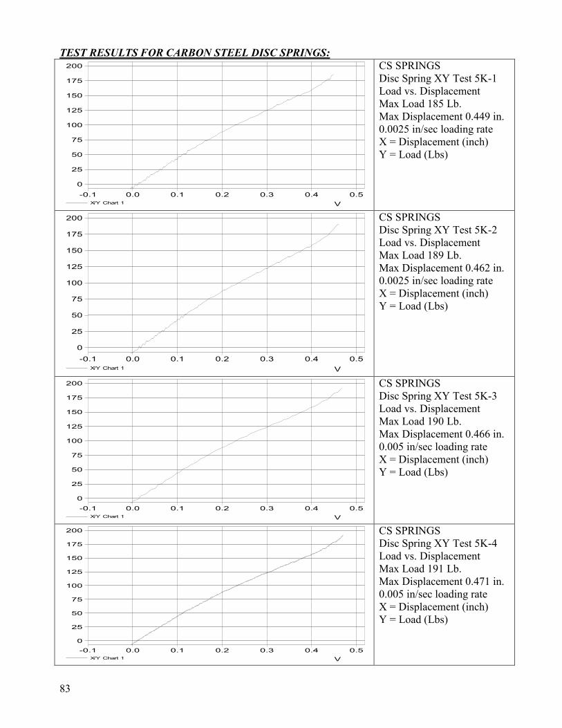
83
TEST RESULTS FOR CARBON STEEL DISC SPRINGS:
V
0.50.40.30.20.10.0-0.1
X/Y Chart 1
200
175
150
125
100
75
50
25
0
CS SPRINGS Disc Spring XY Test 5K-1 Load vs. Displacement Max Load 185 Lb. Max Displacement 0.449 in. 0.0025 in/sec loading rate X = Displacement (inch) Y = Load (Lbs)
V
0.50.40.30.20.10.0-0.1
X/Y Chart 1
200
175
150
125
100
75
50
25
0
CS SPRINGS Disc Spring XY Test 5K-2 Load vs. Displacement Max Load 189 Lb. Max Displacement 0.462 in. 0.0025 in/sec loading rate X = Displacement (inch) Y = Load (Lbs)
V
0.50.40.30.20.10.0-0.1
X/Y Chart 1
200
175
150
125
100
75
50
25
0
CS SPRINGS Disc Spring XY Test 5K-3 Load vs. Displacement Max Load 190 Lb. Max Displacement 0.466 in. 0.005 in/sec loading rate X = Displacement (inch) Y = Load (Lbs)
V
0.50.40.30.20.10.0-0.1
X/Y Chart 1
200
175
150
125
100
75
50
25
0
CS SPRINGS Disc Spring XY Test 5K-4 Load vs. Displacement Max Load 191 Lb. Max Displacement 0.471 in. 0.005 in/sec loading rate X = Displacement (inch) Y = Load (Lbs)
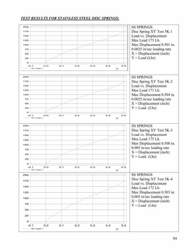
84
TEST RESULTS FOR STAINLESS STEEL DISC SPRINGS:
V
0.50.40.30.20.10.0-0.1
X/Y Chart 1
200
175
150
125
100
75
50
25
0
SS SPRINGS Disc Spring XY Test 5K-1 Load vs. Displacement Max Load 173 Lb. Max Displacement 0.501 in. 0.0025 in/sec loading rate X = Displacement (inch) Y = Load (Lbs)
V
0.50.40.30.20.10.0-0.1
X/Y Chart 1
200
175
150
125
100
75
50
25
0
SS SPRINGS Disc Spring XY Test 5K-2 Load vs. Displacement Max Load 171 Lb. Max Displacement 0.504 in. 0.0025 in/sec loading rate X = Displacement (inch) Y = Load (Lbs)
V
0.50.40.30.20.10.0-0.1
X/Y Chart 1
200
175
150
125
100
75
50
25
0
SS SPRINGS Disc Spring XY Test 5K-3 Load vs. Displacement Max Load 175 Lb. Max Displacement 0.508 in. 0.005 in/sec loading rate X = Displacement (inch) Y = Load (Lbs)
V
0.50.40.30.20.10.0-0.1
X/Y Chart 1
200
175
150
125
100
75
50
25
0
SS SPRINGS Disc Spring XY Test 5K-4 Load vs. Displacement Max Load 172 Lb. Max Displacement 0.503 in. 0.005 in/sec loading rate X = Displacement (inch) Y = Load (Lbs)
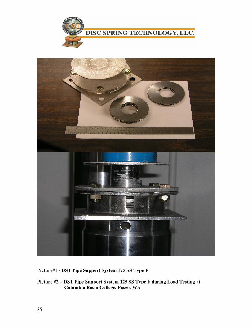
85
Picture#1 - DST Pipe Support System 125 SS Type F Picture #2 – DST Pipe Support System 125 SS Type F during Load Testing at Columbia Basin College, Pasco, WA
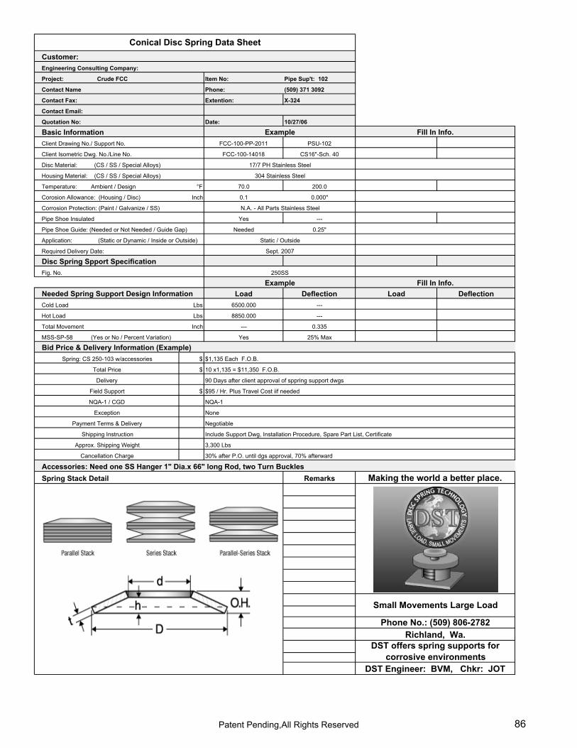
LCustomer:
Project: Crude FCC Item No: Pipe Sup't: 102
Phone: (509) 371 3092
Extention: X-324
Date: 10/27/06
Basic InformationClient Drawing No./ Support No. FCC-100-PP-2011 PSU-102
Client Isometric Dwg. No./Line No. FCC-100-14018 CS16"-Sch. 40
Disc Material: (CS / SS / Special Alloys)
Housing Material: (CS / SS / Special Alloys)
Temperature: Ambient / Design °F 70.0 200.0
Corosion Allowance: (Housing / Disc) Inch 0.1 0.000"
Corrosion Protection: (Paint / Galvanize / SS)
Yes ---
Needed 0.25"
Application:
Required Delivery Date:
Disc Spring Spport Specification Fig. No.
Load Deflection Load DeflectionCold Load Lbs 6500.000 ---
Hot Load Lbs 8850.000 ---
Total Movement Inch --- 0.335
MSS-SP-58 (Yes or No / Percent Variation) Yes 25% Max
$
$
$
Spring Stack Detail Remarks
Contact Email:
Quotation No:
Contact Name
Engineering Consulting Company:
Contact Fax:
Conical Disc Spring Data Sheet
Making the world a better place.
Cancellation Charge
3,300 Lbs
Include Support Dwg, Installation Procedure, Spare Part List, CertificateShipping Instruction
30% after P.O. until dgs approval, 70% afterward
Static / Outside
Phone No.: (509) 806-2782Richland, Wa.
DST Engineer: BVM, Chkr: JOT
Small Movements Large Load
DST offers spring supports for corrosive environments
10 x1,135 = $11,350 F.O.B.
$95 / Hr. Plus Travel Cost iif needed
NQA-1
None
Accessories: Need one SS Hanger 1" Dia.x 66" long Rod, two Turn Buckles
N.A. - All Parts Stainless Steel
Approx. Shipping Weight
Delivery 90 Days after client approval of sppring support dwgs
Bid Price & Delivery Information (Example)$1,135 Each F.O.B.
Example250SS
Needed Spring Support Design Information
Negotiable
NQA-1 / CGD
Exception
Payment Terms & Delivery
Spring: CS 250-103 w/accessories
Total Price
Field Support
Example
17/7 PH Stainless Steel
304 Stainless Steel
Pipe Shoe Insulated
Pipe Shoe Guide: (Needed or Not Needed / Guide Gap)
(Static or Dynamic / Inside or Outside)
Sept. 2007
Fill In Info.
Fill In Info.
Patent Pending,All Rights Reserved 86
87
Terms and Conditions Guarantee: We guarantee for one year from date of delivery our manufactured products to the extent that we replace those having manufacturing defect when used for the purpose which we recommended Claims:
1) Any use of DST products in a manner, which is not intended, will result in voidance of above guarantee.
2) No claims for shortages allowed unless made in writing within ten days of receipt of goods.
3) All rights are reserved by DST; unauthorized use of any information contained in this catalog is strictly prohibited.
Disclaimer:
1) DST reserves the rights to change and/or improve the spring support design, specification, and drawings without any notification. Every effort has been made to assure the accuracy of information contained in this catalog. DST does not accept any responsibility or liability due to inaccuracies resulting from undetected errors and omissions.
2) All materials sent out will be carefully examined, counted and packed. Claims for goods damaged or lost in transit should be made on the carrier, as our responsibility ceases on delivery to the carrier.
Returns: DST cannot accept the return of any spring support products unless an authorized DST person has given written agreement in which case it will be credited subject to the following:
1) Any returned materials to our plant must be found in its original first class condition. If not, DST reserves the rights to deduct a reasonable, fare value from the purchase order price.
2) A minimum of 25% charge will be applied to reduce the purchase order price. 3) Transportation charges, if not prepaid, will be deducted from the purchase order price.
Special Orders: Orders covering special or non-standard goods are not subject to cancellation except on such terms as we may specify on application. Taxes: To the prices and terms quoted, there will be any sales tax payable on the transaction. Freight Allowance: All prices are F.O.B. factory or point of shipment with no freight allowed.

DST Spring Supports Help Meet Following Codes & Standards:ASME Vessel Codes: B&PV Section VIII, Div. 1 & Div.2ASME Piping Codes: B31.1, B31.3 & B31.8API Standards: API 610, APT 617, API 661 API 662, API 620, API 650 & API 653 NEMA : SM-23
ApplicationsVessel Nozzles•Turbine Nozzles•Piggy Back Heat Exchangers•Pump & Condensate Skids•Fan Nozzles•
Large Loads, Small Movements •Limited Piping Layout Space•Marine Applications•
Corrosive Environments•Cryogenics•High Temperature Environments•
Pump Nozzles•Compressor Nozzles•Plate & Frame Heat Exchangers•HVAC Duct Supports •Close Couple Piping•
DST Spring Supports are Suitable For: