Embed Size (px)
Citation preview
1
Paralleling CTs for Line Current Differential Applications: Problems and Solutions
David Costello, Jason Young, and Jonas Traphoner, Schweitzer Engineering Laboratories, Inc. 2350 NE Hopkins Court, Pullman, WA 99163 USA, +1.509.332.1890
Abstract—Paralleling current transformers (CTs) is a common practice in differential or line protection applications where the number of CTs exceeds the number of relay current inputs. This is especially true of line current differential applications applied to breaker-and-a-half and ring-bus configurations. This paper discusses complications that can arise from this practice and highlights relay design improvements that have been made to add security to these applications. Real-world event reports are shown to illustrate problems and solutions.
I. INTRODUCTION There are many principles that protection engineers must
learn. For example, one principle is that paralleled current transformers (CTs) should be avoided as differential (87) inputs because a relay is less secure during external faults with heavy CT saturation. Another is that tapping a multiratio CT at less than its full winding derates the CT and makes it more likely to saturate.
It was Douglas MacArthur who said, “Rules are mostly made to be broken …” [1]. While protection engineers are rarely known for their cavalier attitudes, engineers are tasked with solving problems and have to make compromises for a number of reasons. For example, CTs were paralleled to line current differential relays for decades because the line terminals to be protected were breaker-and-a-half arrangements and each relay available and installed at the time only had a single three-phase current input available. While not ideal for restraint during external faults, paralleled CTs have been used successfully for these dual-breaker applications, and to remove transformers and bus sections from differential zones. Also, CTs are sometimes tapped down in order to meter low load currents or to match the ratio of a paralleled CT. While not ideal for performance during faults, dual-slope and Alpha Plane differential characteristics, as well as adaptive overcurrent elements, external fault detectors, and more, are tolerant of varying levels of CT saturation.
In this paper, two case studies are presented. In both, a fault occurred and an adjacent unfaulted line section misoperated. The subsequent root cause analysis revisits the two fundamental protection principles mentioned previously and their importance. We share the lessons learned and offer some practical advice for improving security.
II. CT CONNECTIONS The method of wiring CTs that is chosen for a given
application is typically driven by the system configuration and protective relay design. For example, to protect a delta-wye transformer with an electromechanical 87 relay, the CTs on
the delta winding must be connected in wye, while the CTs on the wye winding must be connected in delta in order to compensate for the phase angle shift and zero-sequence current introduced by the transformer. On the other hand, both CTs can be connected in wye when a digital 87 relay with internal mathematical compensation is used.
We must decide if a CT can supply multiple relays or if separate, designated CTs are required for each relay. One such case of particular importance is bus 87 protection. A low-impedance bus 87 relay can share CTs with other devices, while a high-impedance bus 87 relay requires dedicated CTs.
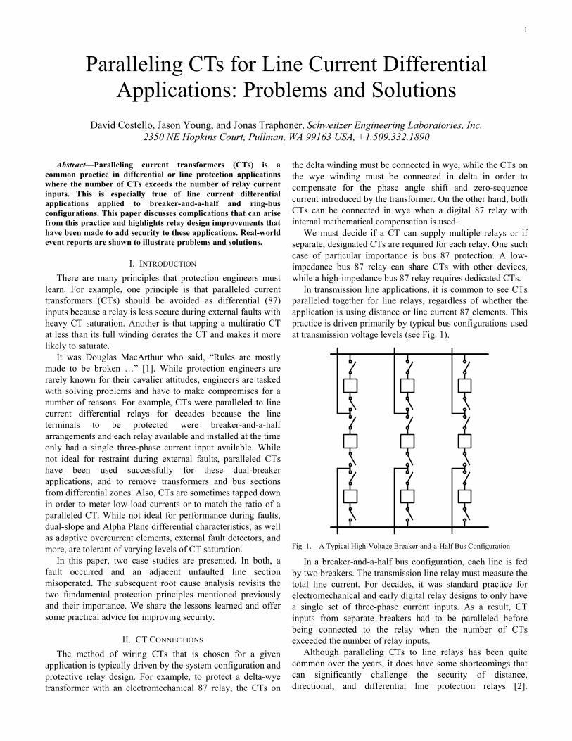
In transmission line applications, it is common to see CTs paralleled together for line relays, regardless of whether the application is using distance or line current 87 elements. This practice is driven primarily by typical bus configurations used at transmission voltage levels (see Fig. 1).
Fig. 1. A Typical High-Voltage Breaker-and-a-Half Bus Configuration
In a breaker-and-a-half bus configuration, each line is fed by two breakers. The transmission line relay must measure the total line current. For decades, it was standard practice for electromechanical and early digital relay designs to only have a single set of three-phase current inputs. As a result, CT inputs from separate breakers had to be paralleled before being connected to the relay when the number of CTs exceeded the number of relay inputs.
Although paralleling CTs to line relays has been quite common over the years, it does have some shortcomings that can significantly challenge the security of distance, directional, and differential line protection relays [2].

2
Therefore, modern digital relays provide additional CT inputs, allowing the individual CTs to be connected separately to the relay.
III. CT SATURATION The source of difference current between two paralleled
CTs for an external fault is CT saturation and the varying performance of the two CTs. A simplified equivalent circuit for two paralleled CTs during an external fault is shown in Fig. 2. Assume that there is a source behind CT A and that the fault is located behind or external to CT B. The coil in the center of Fig. 2 is a current sensor.
I1I2 XMXM
RL RLRCT RCT
IF IF
CT BCT A
Fig. 2. Equivalent Circuit for Two Paralleled CTs During an External Fault
The CT secondary current (IF) is the ratio current, or the primary fault current divided by the CT ratio. XM is the nonlinear excitation branch of the CT, RL is the lead resistance from the CT to the summation point, and RCT is the CT winding resistance. I1 and I2 are the circulating currents. Ideally, the leakage or error current in the excitation branches is minimal, and I1 and I2 are identical to one another and nearly identical to IF. The current sensor should measure 0 amperes. Equation (1) shows the criteria for selecting CTs to avoid saturation [3] [4].
F B STDXI • Z 1 kVR
+ ≤
(1)
where: ZB is the CT burden. k is a dimensioning factor of 7.5 for line 87 applications. VSTD is the secondary terminal voltage rating. IF is the fault current referred to in secondary amperes. X/R is the system reactance-to-resistance ratio.
If the whole winding of a CT is not used, the standard burden is multiplied by the tapped ratio divided by the full ratio. In other words, tapping a CT at less than its full winding derates the CT and lessens its performance.
Despite our best efforts, CT saturation is not always avoidable. Even if CT A and CT B are the same make and model, they may not perform identically during fault conditions. As CT A saturates, its excitation branch current increases dramatically, and I1 is no longer an accurate replica of IF. The difference between I1 and IF is the CT error, which includes a difference in the current magnitude and phase angle.
CTs do not saturate immediately. A CT reproduces the primary current for a certain time after each current zero crossing. The time to saturate is given by (2).
( )SAT
F S BSAT
VX –1I R RRT – ln l – X
R
+ =
ω
(2)
where: ω is the angular frequency. VSAT is the saturation voltage. IF is the fault current referred to in secondary amperes. RS is CT winding resistance. RB is the burden resistance.
Keep in mind that the connection of CTs and the fault type determine the multiplying factors for lead and relay impedances in the burden calculation [5].
Lastly, CTs may succumb to ac or dc saturation. The volt-time area under the burden voltage waveform signifies the threshold of saturation. The volt-time area may be increased due to large ac fault currents (ac or symmetrical saturation) or a large dc offset (dc or asymmetrical saturation). Equation (3) indicates that fault current has a sinusoidal part (ac component) and an exponentially decaying part (dc component). The fault current magnitude, phase angle, and time constant depend on the power system parameters. The magnitude of the dc offset is determined by the angle of the voltage at fault inception.
( ) ( ) ( )RL– tM MV Vi t sin t – – sin – e
Z Z= ω + θ ϕ θ ϕ (3)
where: Z is the system impedance and
( )22 2 2Z R X R L= + = + ω .
ϕ is the system impedance angle and LarctanRω ϕ =
.
X or ωL is the system reactance. R is the system resistance. ω is the angular frequency. VM is the peak system voltage. θ is the angle of the voltage at fault inception.
It is interesting to note the influence of various factors in (3). A higher X/R ratio (higher source impedance) reduces fault current magnitude but increases the time constant or time required to eliminate the dc offset component. In high inductive reactance systems, θ – ϕ = ±90 degrees produces the maximum dc offset. In other words, the dc offset is at a maximum when a fault occurs at a voltage minimum or zero crossing. Insulation breakdown line-to-ground (LG) faults are

3
most likely to occur at a voltage maximum, resulting in little to no dc offset in the fault current. However, in multiphase faults, all voltages cannot be simultaneously zero, so dc offset is inevitable in one or more phases. Fig. 3 shows a plot of the fault current components in (3).
0 1 2 3 4 5Cycles
–30
–20
–10
0
10
20
30
Cur
rent
(kA
)
Steady State
Transient Term
Resultant Current i(t)
Fig. 3. Plot of Fault Current Components
IV. LINE CURRENT DIFFERENTIAL RELAYS
A. General Concepts Differential protection is straightforward in principle.
Gustav Kirchhoff’s first law states that the sum of currents into and out of any node is zero. We implement this principle with differential relays to protect transmission lines, bus sections, power transformers, and generators.
Of course, an 87 relay does not measure primary currents. Compensation may be required for CT-induced and power system element-induced magnitude and phase angle differences. In transmission line or IEC 61850-9-2 process bus applications, the simple 87 principle is further complicated by distributed digital signal processing, communications, and alignment. A generic 87 relay, along with these complicating functions, is shown in Fig. 4.
Power System Element
Magnitude and Angle
Compensation
Magnitude and Angle
Compensation
Data Communications
and Time Alignment
IL IR
IOP
87 Relay
L R
Fig. 4. Functional Current Differential Relay Diagram
For normal power flow or for external faults, we expect that the current IL is nearly equal in magnitude and opposite in phase angle from IR after compensation, data communications, and time alignment. The difference current, IOP, is the phasor sum of IL and IR. IOP should be nearly zero under these ideal conditions.
B. Traditional Slope-Based Differential Characteristic For external faults where significant CT saturation can
occur, an error signal presents itself as false difference current, IOP. The traditional slope-based differential characteristic (see Fig. 5) adds security by adjusting sensitivity based on restraint current.
IOP = KIRT
Restraining Region
Operating Region
IRT
K0
IOP
K2K1
Fig. 5. Traditional Slope-Based Differential Characteristic
Restraint current, IRT, is calculated as the sum of the magnitudes of IL and IR. In some designs, the sum of magnitudes is further multiplied by a constant. In any case, restraint is a measure of current magnitude in the CTs. As current increases, IRT increases, and the operate current required to trip goes up according to a slope constant, K. K0 is the relay minimum sensitivity.
C. Improved Slope-Based Differential Characteristic Improved slope-based differential relays have an adaptive
characteristic. For internal faults, these relays use a lower, more sensitive slope, K1. For external faults, these relays shift to a higher, more secure slope, K2. See Fig. 6.
Restraining Region
Operating Region
IRT
K0
IOP
K1
K2
Fig. 6. Improved Slope-Based Differential Adaptive Characteristic
Waiting for CT saturation to occur, detecting it, and then finally shifting to a more secure state is not reliable. Therefore, adaptive relays detect the fault situation (an external fault) that presents a security risk if the CTs were to saturate severely. The decision to shift to K2 is made by an external fault detector (see Fig. 7) before the CT saturates.
–+
–+
DIOPP
DIRTP
DIRTR
DIOPRDIOP
DIRT
∆IOPR
∆IRTR
Fig. 7. External Fault Detector for Adaptive Characteristic Relays
Raw samples are used to develop raw IOP and raw IRT
values. If there is a difference in the raw IOP and raw IRT values

4
greater than thresholds DIOPP and DIRTP, respectively, from one cycle before, then fast change detectors DIOP and DIRT assert. Even with severe CT saturation, we expect CTs to produce some valid output for at least 2 milliseconds. For external faults, the raw IOP does not change and the raw IRT changes in the first instant of the fault data. The output of the logical AND gate indicates an external fault and drives the adaptive characteristic to the more secure K2 before the CT saturates.
D. Alpha Plane Differential Characteristic Alpha Plane characteristic relays plot the ratio of remote
and local current on a two-dimensional plane. The restraining region of the Alpha Plane is defined by a radius and angle (see Fig. 8). For an external power flow or fault condition, IL and IR ideally should be equal and opposite in phase angle. On the Alpha Plane, the current ratio for this condition would plot at a magnitude of 1 per unit and an angle of 180 degrees. An operating point that lies within the Alpha Plane restraining region is equivalent to a point below the slope line in Fig. 5 or Fig. 6.
Re(k)
Im(k)
Operating Region
RestrainingRegion
Radi
us
–1
Angle
Fig. 8. Alpha Plane Differential Characteristic
The 87 element operates when the current ratio leaves the restraining region and IOP exceeds a minimum pickup value. IL and IR may represent phase currents, negative-sequence currents, or zero-sequence currents. Fig. 9 shows a simplified A-phase 87 element logic diagram; other phase and sequence elements are similar.
E. Generalized Alpha Plane Differential Characteristic In modern generalized Alpha Plane relays, IL and IR are
composite signals, which are functions of IOP and IRT. IOP and IRT are adjustable in order to further secure the 87L element for in-line transformer applications, line charging current compensation, and more. Additionally, the generalized Alpha Plane relays employ an external fault detector, described previously, which expands the restraining region and security.
F. Multiple CT Input Considerations Why are paralleled CTs less secure as differential relay
inputs? For external faults, the 87 relay is not able to measure the true local restraint current (the sum of the Breaker 1 and Breaker 2 current magnitudes). Instead, the local restraint current is only the difference or error between these two signals. Fig. 10 shows a typical external CT summation connection.
Recall from the slope-based differential characteristic shown in Fig. 5 that higher restraint magnitude equates to more security and that lower restraint magnitude means the relay is more sensitive. For external faults, we want the relay to be as secure as possible. However, the CT connection shown in Fig. 10 limits the ability of the relay to be secure by hiding restraint current. Consider faults where the remote current contribution, IR, is zero; the local operate or difference signal is the same as the local restraint signal.
87LA1/8
0
1
1
–
+
87LPF(setting)
Alpha Plane
Settings87LANG, 87LR
87LOPA∑
R87LA
IAL
IAR H
|IAL + IAR|
Fig. 9. Alpha Plane Differential Characteristic Relay Trip Logic

5
1 2
IR IL1 + IR
∑
IL1
Line
••••••
Fig. 10. Typical External CT Summation Connection When the Number of CTs Exceeds the Number of Relay Current Inputs
Today, for multiple breaker terminals, modern relays are available with multiple CT inputs (see Fig. 11). These relays measure the individual CT signals for metering and breaker failure functions, as well as for better restraint for the 87L element.
1 2
IR IL1 + IR
∑
IL1
Line
••••••
1 2
Fig. 11. Modern Relay With Multiple CT Inputs
Consider faults where the remote current contribution, IR, is zero; now, any local operate or difference signal is much less than the sum of the individual CT magnitudes. Because the true restraint current is known, the relay is more secure. In addition to allowing more relay inputs, modern 87L relay
security is further enhanced with the generalized Alpha Plane and an external fault detection-driven adaptive characteristic.
For more information on line current differential relays, refer to [6] and [7].
V. CASE STUDY 1 A 92 kV utility transmission line tripped in 2013 when an
adjacent line reclosed a second time into a permanent fault. Fig. 12 shows a simplified one-line diagram of the system.
Line 1 experienced a C-phase-to-ground (CG) fault close to Substation Bravo. The Line 1 protection correctly interrupted the fault twice. When BK24 was reclosed into the fault a second time, the primary relay on Line 2 at Substation Bravo incorrectly operated, tripping BK21 and BK22. At the time of the trip, the remote end of Line 2 (BK33) was open.
The Line 2 primary relay is a digital line current differential relay. This relay only has a single three-phase current input. Because of this and the breaker-and-a-half bus configuration, the BK21 and BK22 CTs were paralleled external to the relay, as shown in Fig. 13. Note that the CTs are also tapped down from 2000:5 to 800:5. Both CTs are rated C800, but the CTs are from different manufacturers.
As discussed previously, paralleling CTs can significantly challenge differential, distance, and directional elements [2]. In this case, both the line current differential and backup distance elements operated. However, in keeping with the focus of this paper, the analysis concentrates on the line current differential operation. Fig. 14 shows the filtered event data captured by the primary relay and the assertion of the elements mentioned previously. The three-phase terminal currents and voltages, as well as relevant digital elements, are shown.
G
BK11
BK12
BK13
BK14
BK15
13.2/92 kV
Substation Alpha
BK16
BK24 BK25 BK26
BK23BK22BK21
Bus A Bus B
BK4192/230 kV
Substation Bravo
CG
BK31
BK32
BK33
Substation Charlie
BK5192/161 kV
Line 2
Line 1
13.2/92 kV
Fig. 12. Simplified One-Line Diagram for Case Study 1

6
BK21 BK22
Bus A
Line 2
Primary 87L/21/67
Secondary21/67
2000:5 2000:5800:5 800:5
2000:5800:5
2000:5800:5
Fig. 13. CTs Paralleled External to the 87 Relay for Case Study 1
Fig. 14. Line 1 Primary Relay Event Data and 87LC and Z1G Assertion
As Fig. 14 shows, the 87LC C-phase element asserted for this fault. For comparison, Fig. 15 shows the time-aligned local and remote currents. Note the lack of remote terminal C-phase current, and recall that the remote end of the line was open at the time of this operation. The voltages corroborate the C-phase event, but note that the voltages shown are not time-aligned with the 87 element currents.
Fig. 15. Primary Relay Filtered Local and Remote Currents
The 87 element used by this relay is of the Alpha Plane characteristic described in Section IV, Subsection D. A basic tenant used in relay design is that phase angles should not be trusted on extremely small signals. Therefore, before the relay plots the ratio of remote to local currents on the Alpha Plane, both the local and remote currents must exceed a minimum threshold. Because the remote end of the line was open, no remote current was available and the Alpha Plane was not enabled. As a result, the only requirement to assert the 87 element was differential current greater than the pickup
setting of 6.5 amperes. Fig. 16 shows the magnitude of the filtered differential current.
Fig. 16. Filtered Differential Current Magnitude
ICTMag in Fig. 16 is the differential current for C-phase. This reached 2,793 amperes primary, or 17.45 amperes secondary, and far exceeded the 87 element pickup setting. While the relay measured difference current and responded as designed and set, the operation of Line 2 for a fault on Line 1 is undesired and is a security failure. The current seen is difference or error current between the local CTs from BK21 and BK22 for the adjacent line fault. The root causes of the misoperation are paralleled CTs, the derating of the CTs by tapping them at less than their full winding, and the unequal performance of the CTs during the external fault.
Fig. 16 shows that the error current is greater than the pickup for 2.75 cycles. Adding a small time delay to the 87 element adds security. However, the drawback to this approach is that it also delays operation for internal faults where speed is important. Furthermore, setting the delay based on this one event does not ensure that the delay will prevent reoccurrence for other faults on the system.
Fig. 17 shows the raw or unfiltered oscillography captured by the 87 relay. Note that the error current is nonsinusoidal and that its peaks appear 1.375 cycles after the C-phase voltage drops at the beginning of the fault.
Fig. 17. Primary Relay Raw or Unfiltered Oscillography
Because the CTs are paralleled external to the relay, Fig. 17 only shows the difference or error between the secondary outputs of these two CTs, which is the result of unequal CT saturation. The delay seen before saturation is typical of dc saturation, where the ac peak is not sufficient to cause CT saturation, but the offset waveform results in offset flux, driving the CT closer to saturation with each passing cycle.
7
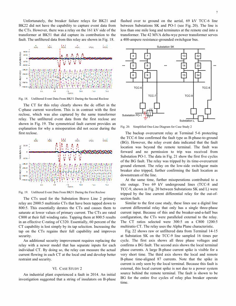
Unfortunately, the breaker failure relays for BK21 and BK22 did not have the capability to capture event data from the CTs. However, there was a relay on the 161 kV side of the transformer at BK51 that did capture its contribution to the fault. The unfiltered data from this relay are shown in Fig. 18.
Fig. 18. Unfiltered Event Data From BK51 During the Second Reclose
The CT for this relay clearly shows the dc offset in the C-phase current waveform. This is in contrast with the first reclose, which was also captured by the same transformer relay. The unfiltered event data from the first reclose are shown in Fig. 19. The symmetrical fault current provides an explanation for why a misoperation did not occur during the first reclose.
Fig. 19. Unfiltered Event Data From BK51 During the First Reclose
The CTs used for the Substation Bravo Line 2 primary relay are 2000:5 multiratio CTs that have been tapped down to 800:5. This essentially derates the CTs and causes them to saturate at lower values of primary current. The CTs are rated C800 at their full winding ratio. Tapping them at 800:5 results in an effective C-rating of C320. Essentially, 60 percent of the CT capability is lost simply by its tap selection. Increasing the tap on the CTs regains their full capability and improves security.
An additional security improvement requires replacing the relay with a newer model that has separate inputs for each individual CT. By doing so, the relay can measure the actual current flowing in each CT at the local end and develop better restraint and security.
VI. CASE STUDY 2 An industrial plant experienced a fault in 2014. An initial
investigation suggested that a string of insulators on B-phase
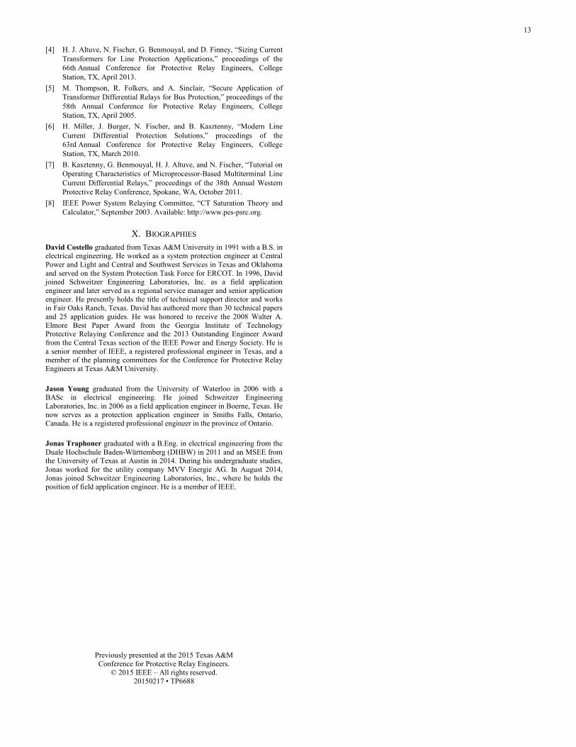
flashed over to ground on the aerial, 69 kV TCC-6 line between Substations SK and PO-1 (see Fig. 20). The line is less than one mile long and terminates at the remote end into a transformer. The 42 MVA delta-wye power transformer serves a 400-ampere resistance-grounded switchgear bus.
4 7
5 8
6 9
13 32
14 33
15 34
•••••• •••
TCC-6
TCC-7
Substation PO-1
TCC-8
TCC-9
Substation L
Substation SK
Fig. 20. Simplified One-Line Diagram for Case Study 2
The backup overcurrent relay at Terminal 5-6 protecting the TCC-6 line confirmed the fault type as B-phase-to-ground (BG). However, the relay event data indicated that the fault location was beyond the remote terminal. The fault was forward and no permission to trip was received from Substation PO-1. The data in Fig. 21 show the first five cycles of the BG fault. The relay was tripped by its time-overcurrent ground element. The relay on the low-side switchgear main breaker also tripped, further confirming the fault location as downstream of the line.
At the same time, further misoperations contributed to a site outage. Two 69 kV underground lines (TCC-8 and TCC-9, shown in Fig. 20 between Substations SK and L) were tripped by the line current differential relay for the out-of-section fault.
Similar to the first case study, these lines use a digital line current differential relay that only has a single three-phase current input. Because of this and the breaker-and-a-half bus configuration, the CTs were paralleled external to the relay. The CT ratios selected were 300:5 on a C800 1200:5 multiratio CT. The relay uses the Alpha Plane characteristic.
Fig. 22 shows raw or unfiltered data from Terminal 14-15 at Substation SK on the TCC-9 line sampled 16 times per cycle. The first axis shows all three phase voltages and confirms a BG fault. The second axis shows the local terminal phase currents. A large B-phase current spike is visible for a very short time. The third axis shows the local and remote B-phase time-aligned 87 currents. Note that the spike in current is only seen by the local terminal. Because this fault is external, this local current spike is not due to a power system source behind the remote terminal. The fault is shown to be BG for the entire five cycles of relay plus breaker operate time.

8
–40,000
–20,000
0
20,000
40,000
9 10 11 12 13 14
Cur
rent
(A)
–80
–40
0
40
80
Vol
tage
(kV
)
9 10 11 12 13 14
9 10 11 12 13 14
1:RMB1A1:PTRX
1:RMB2A1:67N1T
1:67N11:51P1:51N
1:50N1
1:IB
1:IC
1:IA
1:VB_kV
1:VC_kV
1:VA_kV
Cycles
Fig. 21. Substation SK Terminal 5-6 Sees a Forward BG Fault
1:87L1:87LB
1:87LOPB1:R87LB
24.970713 25.020713 25.070713 25.120713 25.170713 25.220713
24.970713 25.020713 25.070713 25.120713 25.170713 25.220713
24.970713 25.020713 25.070713 25.120713 25.170713 25.220713
24.970713 25.020713 25.070713 25.120713 25.170713 25.220713–80
–40
0
40
80
Vol
tage
(kV
)C
urre
nt (A
)C
urre
nt (A
)
–2000
200400600800
–200
0
200
400
600
1:VA_kV
1:VB_kV
1:VC_kV
1:IA
1:IB
1:IC
1:IBL
1:IBX
Time (s)
Fig. 22. Raw Data From Terminal 14-15 on the TCC-9 Line During the Fault

9
Fig. 23 shows the beginning of the BG fault. These are raw or unfiltered data. The first axis shows the local 87 phase currents. The second axis shows the remote 87 phase currents. The digital element 1:R87LB is the Alpha Plane restraint dropping out. Element 1:87LOPB shows when the difference current magnitude exceeds pickup. Elements 1:87LB and 1:87L indicate that the 87 element trips after a 1/8-cycle security delay. The time between the raw or unfiltered current spike and the element assertion is due to a filtering delay.
25.020713 25.040713 25.060713 25.080713–200
0200400600
Cur
rent
(A)
25.020713 25.040713 25.060713 25.080713–100
–402080
Cur
rent
(A)
25.020713 25.040713 25.060713 25.0807131:R87LB
1:87L1:87LB
1:87LOPB
1:IAL1:IBL1:ICL
1:IAX1:IBX1:ICX
Time (s) Fig. 23. Terminal 14-15 on the TCC-9 Line During the Fault
A separate breaker failure relay for Terminal 14-15 recorded a high-resolution COMTRADE event, which showed individual CT data sampled 2,000 times per second. In Fig. 24, the first axis shows the B-phase current from Breaker 14. The second axis shows the B-phase current from Breaker 15, which is nearly equal and opposite of Breaker 14. The magnitude of the current flowing in one breaker and out of the other, from one bus to another during the fault, was much larger than the current from the remote terminal across the line. The two CT currents were mathematically summed using an event analysis software tool. The spike of difference or error current in the third axis matches that seen by the 87 relay.
25.045581 25.065581 25.085581 25.105581 25.125581
25.045581 25.065581 25.085581 25.105581 25.125581
25.045581 25.065581 25.085581 25.105581 25.125581
–8,000–4,000
04,0008,000
–10,000–6,000–2,000
2,0006,000
–200200600
1,0001,400
Cur
rent
(A)
Cur
rent
(A)
Cur
rent
(A)
1:IAW1:IBW1:ICW
1:IAX1:IBX1:ICX
1:IB_SUM
Time (s) Fig. 24. Raw Individual CT 14-15 Currents From Breaker Failure Relay
Fig. 25 shows the same data from the breaker failure relay. However, to better compare the output from the two CTs, one CT polarity has been mathematically reversed. The two current outputs are plotted together on the first axis. The difference or error between the two CTs can now be seen more easily. The CT outputs differ for only 1/4 cycle. The second axis is the summation or difference current. These currents are symmetrical, indicating that the CT error is due to ac saturation.
–8,000
–4,000
0
4,000
8,000
25.030581 25.040581 25.050581
25.030581 25.040581 25.050581–200
200600
1,0001,400
Cur
rent
(A)
Cur
rent
(A)
1:IBW1:IBX_NEG
1:IB_SUM
Time (s) Fig. 25. The Difference or Error Between CTs From Breakers 14 and 15
A different scenario played out on the TCC-8 line. Fig. 26 shows the event data from the line current differential relay at Terminal 32-33 at Substation SK on the TCC-8 line. The first axis shows the line phase currents. The second axis shows the terminal voltages.
25.091352 25.141352 25.191352 25.241352 25.291352–2,000
–1,000
0
1,000
25.091352 25.141352 25.191352 25.241352 25.291352–80
–40
0
40
80
Cur
rent
(A)
Vol
tage
(kV
)
1:IB1:IC
1:IA
1:VB_kV1:VC_kV
1:VA_kV
Time (s) Fig. 26. Filtered Difference or Error Current and Voltages on the TCC-8 Line
First, observe that the fault data are about 11 cycles long. The first six cycles are the BG fault. Then, the fault evolves into an A-phase-to-B-phase-to-ground (ABG) fault. This change was not seen in the previous data because the TCC-9 line tripped immediately.

10
Second, unlike the 87 relay on the TCC-9 line that measured difference current almost immediately at the onset of the fault, the relay on the TCC-8 line measures difference current at the transition between fault types. Recall that multiphase faults are more likely to have dc offset in the fault current on at least one phase. In fact, note that the difference current seen in the TCC-8 line data is actually on A-phase, rather than B-phase.
A separate breaker failure relay for Breakers 32 and 33 recorded a high-resolution COMTRADE event, which showed individual CT data. In Fig. 27, the first axis shows the three phase currents from Breaker 32. The second axis shows the three phase currents from Breaker 33. The third axis shows the difference or error between the two CTs. Note that the error current is on A-phase, that the error occurs when the fault evolves from BG to ABG, and that both CT A-phase signals are distorted.
–6,000–2,000
2,0006,000
–6,000–2,000
2,0006,000
–1,0001,0003,0005,000
25.132706 25.182706 25.232706 25.282706
25.132706 25.182706 25.232706 25.282706
25.132706 25.182706 25.232706 25.282706
Cur
rent
(A)
Cur
rent
(A)
Cur
rent
(A)
1:IAW1:IBW1:ICW
1:IAX1:IBX1:ICX
Time (s)
1:IA_SUM1:IB_SUM
Fig. 27. Raw Individual Breaker 32 and 33 Currents From Breaker Failure Relay
Fig. 28 shows the same data from the breaker failure relay. However, to better compare the output from the two CTs, one CT polarity has been mathematically reversed.
25.192706 25.196706 25.200706 25.204706
25.192706 25.196706 25.200706 25.204706–1,000
1,000
3,000
5,000
–6,000
–2,000
2,000
6,000
Cur
rent
(A)
Cur
rent
(A)
1:IAW1:IAXNEG
Time (s)
1:IA_SUM
Fig. 28. The Difference or Error Between CTs From Breakers 32 and 33
The two current outputs are plotted together on the first axis. The difference or error between the two CTs can now be seen more easily. The CT outputs differ for 6 milliseconds in the raw or unfiltered event data. The second axis is the summation or difference current. These currents are asymmetrical, indicating that the CT error is due to dc saturation.
As with the first case study, the difference or error current is only present for a short time. Adding a small time delay to the 87 element adds security. Fig. 29 shows the result of replaying the Terminal 14-15 raw event data into a similar relay with externally paralleled CTs that now includes a one-cycle delay on the 87 element. With this delay, the relay remains secure.
However, the drawback to this approach is that it also delays operation for internal faults where speed is important. Furthermore, setting the delay based on this one event does not ensure that the delay will prevent reoccurrence for other faults on the system.
The CTs used for the Substation SK relays are 1200:5 multiratio CTs that have been tapped down to 300:5. This essentially derates the CTs and causes them to saturate at lower values of primary current. The CTs are rated C800 at their full winding ratio. Tapping them at 300:5 results in an effective C-rating of C200. Essentially, 75 percent of the CT capability is lost simply by its tap selection. Increasing the tap on the CTs regains their full capability and improves security. This is the solution that was implemented at the industrial plant.
–200
200
600
1,000
37.310708 37.350708 37.390708
37.310708 37.350708 37.390708
1:TRIP1:SV1T
1:SV11:R87LB
1:87LOPB1:87LB
Cur
rent
(A)
1:IBL1:IBX
Time (s)
Fig. 29. Positive Effect of a Short Time Delay
Fig. 30 shows the output of the IEEE Power System Relaying Committee (PSRC) “CT Saturation Theory and Calculator” [8].
–0.017 0.017 0.050 0.083 0.117 0.150
–0.017 0.017 0.050 0.083 0.117 0.150–30
0
30
–150
0
150
Cur
rent
(A)
Cur
rent
(A)
Time (s)
Fig. 30. CT Performance at 300:5 (Top) and 1200:5 (Bottom) Taps

11
The CT saturation tool allows us to visualize CT performance at different taps, with varying levels of remanence flux, changing burdens, and more. Fig. 30 is shown with no remanence and maximum dc offset. The first axis shows the CT output on the 300:5 tap. The second axis shows the improved performance on the 1200:5 tap.
Unlike the event in the first case study, the TCC-8 and TCC-9 lines had both line ends closed during the fault. Therefore, the 87 relays calculated the Alpha Plane characteristic. An event analysis tool allows us to simulate the relay performance with expanded Alpha Plane angle settings.
Fig. 31 shows the TCC-9 line data from the perspective of Substation L. The original Alpha Plane angle setting during the fault was 195 degrees. In Fig. 31, the angle has been expanded to its maximum allowed setting of 270 degrees. For a relay with a slope-based differential characteristic, this is equivalent to increasing the slope setting. Each point represents a processing interval, and the relay would have tripped even if the Alpha Plane restraining region had been expanded. Analysis of the TCC-8 line data showed similar results. In addition to not preventing the misoperation, expanding the restraining region could have the adverse effect of delaying or preventing tripping for an internal fault with similar CT saturation.
Im
Re8.06.04.02.0
Fig. 31. Effect of Increasing the Alpha Plane Angle Setting
In addition to increasing the CT taps, another solution requires replacing the relay with a newer model that has separate inputs for each individual CT. By doing so, the relay can measure the actual current flowing in each CT at the local end and develop better restraint and security. To prove this solution, the Terminal 14-15 COMTRADE data were replayed into a modern relay that measures separate CT inputs. In
addition to measuring the individual breaker CTs, this modern digital relay uses the generalized Alpha Plane characteristic and an external fault detector for added security.
Fig. 32 shows the individual CT 14-15 currents measured by the modern 87 relay. These data simply match the data from Fig. 24 that were used as the source information for the test. Fig. 33 shows the difference current spike seen by the original differential relay that used externally paralleled CTs (first axis) and the difference current spike seen by the modern relay that combines these signals mathematically (second axis). Regardless of physical or mathematical summation, the difference current that is seen is the same.
–10,000–6,000–2,000
2,0006,000
37.871081 37.971081 38.071081
1:IAW1:IAX1:IBW1:IBX1:ICW1:ICXC
urre
nt (A
)
Time (s)
Fig. 32. Individual CT 14-15 Currents Measured by Modern 87 Relay
–200
0
200
400
600
25.005581 25.045581 25.085581
25.005581 25.045581 25.085581–400
0
400
800
1,200
2:IA2:IB2:IC
1:IA_COMBINED1:IB_COMBINED1:IC_COMBINED
Time (s)
Cur
rent
(A)
Cur
rent
(A)
Fig. 33. Physically and Mathematically Combined Currents Show the Same Difference or Error
Fig. 34 shows the response of the original relay (trip) and the modern relay (no trip). The first axis shows the difference current spike seen by the modern relay with replayed event data. The second axis shows the difference current seen by the original relay during the fault. The digital elements in the third axis show that the original relay trips (2:DD, 2:87L, and 2:TRIP87 assert) and that the modern relay remains secure and does not trip (1:87L deasserted). This is because the modern relay, while seeing the same difference signal, uses the independent CT information to detect an external fault (1:87EFD and 1:87EFDL assert), shift to more secure settings, and add restraint to the differential calculation.

12
1:87EFD1:87EFDL2:TRIP87
2:DD1:87L2:87L
07.994706 08.044706 08.094706
07.994706 08.044706 08.094706
07.994706 08.044706 08.094706
–200
0
200
400
600
800C
urre
nt (A
)C
urre
nt (A
)
–200
200
600
1,000
1,400 1:IB_COMBINED
2:IB
Time (s) Fig. 34. Modern Relay Does Not Trip for Replayed Event Data
VII. CONCLUSION It has been a common practice in power system protection
to parallel CTs with transmission relays due to typical bus configurations and limited current inputs to these relays. Different relay designs have varying tolerance for and security during CT errors. While the vast majority of these installations have been secure and have operated admirably, it has been shown that this practice can present significant challenges to the security of line current differential relays when the CTs are exposed to fault currents that drive them into saturation. Compounding the challenge for the relay, sometimes CTs are tapped down and derated even further in these applications.
The two case studies illuminate these challenges and their risks to security. In both cases, CTs saturated during external faults on adjacent lines. AC and dc saturation were on display in the case studies. In both cases, CTs were externally paralleled and were significantly tapped down from the maximum ratio.
Several possible solutions to mitigate these issues have been presented when dealing with in-service applications. These include adding a short tripping time delay and adjusting the Alpha Plane angle or slope setting. These two solutions alone, however, cannot guarantee security for all fault conditions, and they risk dependability and slow tripping for internal faults. Any change in the Alpha Plane angle or slope setting should only be made after thoughtful review and extensive power system simulations.
Another solution includes using the maximum CT ratio when paralleling CTs to improve the CT performance. In the case studies shared in this paper, increasing the CT tap to the full winding was a recommended solution. Additionally, adding a short delay (one-cycle maximum) for phase differential elements on relays with externally paralleled CTs, along with using the maximum CT ratio, may be an acceptable
compromise between dependability and added security if it is determined that CT saturation is still possible. The IEEE PSRC “CT Saturation Calculator” is an excellent tool to evaluate CT performance [8].
The final solution, admittedly best considered for new installations in the future or for particularly troublesome in-service applications, is to install a modern digital 87 relay. This relay should have an external fault detector or other adaptive characteristic for increased security and separate current inputs for each CT to avoid paralleling CTs external to the relay. While it is true that modern relays allow CT performance requirements to be relaxed when compared with previous generations of protection, as the testing in this paper proves, the authors strongly recommend using the maximum CT ratio and the best possible CTs even with the modern relays.
VIII. ACKNOWLEDGMENTS The authors express their sincere appreciation to Mr. Bill
Fleming for the fault current calculation spreadsheet, to Mr. Glen Swift and the IEEE PSRC for the “CT Saturation Calculator tool,” to Mr. Gabriel Benmouyal for reviewing our text, and to the engineers and companies who shared original event data and assisted with root cause analysis.
IX. REFERENCES [1] W. A. Ganoe, MacArthur Close-Up. Vantage Press, New York, 1962. [2] B. Kasztenny and I. Voloh, “Application of Distance and Line Current
Differential Relays in Breaker-and-a-Half Configurations,” proceedings of the IEEE Power and Energy Society Transmission and Distribution Conference and Exhibition, Dallas, TX, May 2006.
[3] G. Benmouyal, J. Roberts, and S. E. Zocholl, “Selecting CTs to Optimize Relay Performance,” proceedings of the 23rd Annual Western Protective Relay Conference, Spokane, WA, October 1996.
13
[4] H. J. Altuve, N. Fischer, G. Benmouyal, and D. Finney, “Sizing Current Transformers for Line Protection Applications,” proceedings of the 66th Annual Conference for Protective Relay Engineers, College Station, TX, April 2013.
[5] M. Thompson, R. Folkers, and A. Sinclair, “Secure Application of Transformer Differential Relays for Bus Protection,” proceedings of the 58th Annual Conference for Protective Relay Engineers, College Station, TX, April 2005.
[6] H. Miller, J. Burger, N. Fischer, and B. Kasztenny, “Modern Line Current Differential Protection Solutions,” proceedings of the 63rd Annual Conference for Protective Relay Engineers, College Station, TX, March 2010.
[7] B. Kasztenny, G. Benmouyal, H. J. Altuve, and N. Fischer, “Tutorial on Operating Characteristics of Microprocessor-Based Multiterminal Line Current Differential Relays,” proceedings of the 38th Annual Western Protective Relay Conference, Spokane, WA, October 2011.
[8] IEEE Power System Relaying Committee, “CT Saturation Theory and Calculator,” September 2003. Available: http://www.pes-psrc.org.
X. BIOGRAPHIES David Costello graduated from Texas A&M University in 1991 with a B.S. in electrical engineering. He worked as a system protection engineer at Central Power and Light and Central and Southwest Services in Texas and Oklahoma and served on the System Protection Task Force for ERCOT. In 1996, David joined Schweitzer Engineering Laboratories, Inc. as a field application engineer and later served as a regional service manager and senior application engineer. He presently holds the title of technical support director and works in Fair Oaks Ranch, Texas. David has authored more than 30 technical papers and 25 application guides. He was honored to receive the 2008 Walter A. Elmore Best Paper Award from the Georgia Institute of Technology Protective Relaying Conference and the 2013 Outstanding Engineer Award from the Central Texas section of the IEEE Power and Energy Society. He is a senior member of IEEE, a registered professional engineer in Texas, and a member of the planning committees for the Conference for Protective Relay Engineers at Texas A&M University.
Jason Young graduated from the University of Waterloo in 2006 with a BASc in electrical engineering. He joined Schweitzer Engineering Laboratories, Inc. in 2006 as a field application engineer in Boerne, Texas. He now serves as a protection application engineer in Smiths Falls, Ontario, Canada. He is a registered professional engineer in the province of Ontario.
Jonas Traphoner graduated with a B.Eng. in electrical engineering from the Duale Hochschule Baden-Württemberg (DHBW) in 2011 and an MSEE from the University of Texas at Austin in 2014. During his undergraduate studies, Jonas worked for the utility company MVV Energie AG. In August 2014, Jonas joined Schweitzer Engineering Laboratories, Inc., where he holds the position of field application engineer. He is a member of IEEE.
Previously presented at the 2015 Texas A&M Conference for Protective Relay Engineers.
© 2015 IEEE – All rights reserved. 20150217 • TP6688