Embed Size (px)
Citation preview

Shunt reactor switching transients at high compensation levels
.
Abstract: Reactor banks play an important role in mitigating the voltage rise, otherwise known as
Ferranti Rise, which is characteristic to long lightly loaded transmission lines having high capacitive
charging current. The energizing and de-energizing of the reactor bank introduces high frequency
transients that might stress the insulation of the switching equipment leading to equipment failures.
The paper presents different phenomena associated with reactor bank energization and
de- energization and addresses the issue of circuit breaker application when interrupting low inductive
currents from an engineering stand point. The paper illustrates a case study simulated in the
Alternative Transients Program part of the Electromagnetic Transients Program package (EMTP-
ATP) to demonstrate current chopping and re-ignition phenomenon associated with reactor bank
switching. Mitigation methods for the aforementioned issues are also evaluated.
Index Terms----Unsymmetrical currents, current chopping, reignition, shunt reactor banks
Introduction:
Shunt reactors are commonly employed in substations as a cost effective way of reducing the voltage
rise, during conditions of low load [7].When the transmission line is loaded below the surge
impedance load (SIL), the line experiences a voltage rise due to the line’s natural shunt capacitance
drawing charging current through the series inductance [13]. Shunt reactors are switched into the
circuit to compensate for this effect. This switching in of reactor bank causes the generation of
unsymmetrical phase energization currents having high magnitudes and large decay constants. These
energization transients are governed by the point on wave operation of the circuit breaker poles [3].
During the periods of heavy loading on the transmission line the reactor bank is switched off. The
bank current is mainly inductive in nature and modern SF6 breakers have a tendency to pre-maturely
chop this current before its natural zero crossing [2]. This is termed as current chopping, which results
in high frequency overvoltages due to the trapped energy oscillating between the reactor bank and its
stray capacitance. Apart from the chopping overvoltages there are transient recovery voltages that
appear across the breaker contact gaps forcing it to reignite. The reactor bank switching imposes
significant switching requirements on the circuit breakers, hence it is crucial to simulate such cases
and adopt appropriate mitigation methods [4] [5].
Himanshu J. Bahirat Michigan Technological University, Department of Electrical and Computer Engg,
Houghton, MI 49931
Phone # 906-487-2947
Dr. Bruce A. Mork Michigan Technological University,
Department of Electrical and Computer Engg,
Houghton, MI 49931
Mythili Chaganti Xcel Energy Inc.
414 Nicollet Mall
Minneapolis, MN 55401
Salil S. Sabade Michigan Technological University, Department of Electrical and Computer Engg, Houghton, MI 49931
Phone # 678-848-0983

+
CBLs
Cs Lp Cp
Lb
CL LAlternatingVoltage Source
Background and Problem definition:
The switching operations are studied and illustrated for an EMTP-ATP study considering the
installation of shunt reactor bank connected to the tertiary winding of a power transformer. This shunt
reactor bank with its associated equipment is planned to be installed at one of the substations owned
by Xcel Energy Inc.
The case study is presented for a 40-Mvar ungrounded wye connected dry-type reactor bank installed
on the 13.8 kV delta tertiary of a 450 MVA autotransformer. Dry type reactors are generally limited to
voltages below 138 kV and can be connected directly to a transmission line or the tertiary of a system
transformer [6]. The latter configuration is quite beneficial in case of any single phase reactor leg
failure and will only have a minor impact on the system load currents. The tertiary connected reactors
are limited to voltages below 72.5 kV [12].
Fig. 1 gives the circuit diagram used to illustrate the reactor bank switching. The figure depicts the
stray capacitances of the reactor, circuit breaker and system bus.
Where:
Ls is the load side inductance CB is the circuit breaker
Cs is the source side capacitance Lb is the connection series inductance
CL is the shunt reactor stray capacitance Lp; Cp is the breaker stray inductance and capacitance
L is the shunt reactor inductance
This paper considers the case of ungrounded reactor bank neutral. The other grounding methods
adopted are solidly grounded and high impedance grounding of neutral. In case of solidly grounded
neutral connection a single phase equivalent of the circuit may be considered for complete analysis.
When we say that the neutral point of the bank is ungrounded this does not mean that the neutral point
is truly isolated from the ground. But this translates into a special case of impedance grounding where
the impedance happens to be capacitive in nature. This exists due to the natural capacitive coupling
between the neutral and the ground [2]
Figure 1: Single-phase equivalent circuit for analysis shunt reactor switching

CAPBANK
82.2 Mvar
Buswork
XFMR
A A
40 MvarCstray Cstray
V
Cn
13.55L -30.
V
343.8L0.007
V
115.9L-0.02
V
Buswork
Reactor Bank
GCB
Simulation set-up & Implementation:
Fig. 2 shows the complete circuit diagram used for the reactor bank switching study. The reactor bank
is connected on the delta side of the autotransformer (XFMR). The system has a capacitor bank
connected on the low voltage (LV) side of XFMR. The network on the LV side of the XFMR is not
modelled to maintain simplicity of the circuit and clearly demonstrate the transients associated with
reactor bank switching. The XFMR is modelled using the Hybrid transformer model in EMTP-ATP
and is based on manufacturers test report. A 40-Mvar ungrounded reactor bank is used in the study.
The floating neutral point of the reactor has stray capacitance associated with it and is shown as Cn in
Fig 2. The circuit breaker (CB) used for switching of reactor bank is modelled as 3 single phase time
controlled switches in ATP. The connection buswork is modelled as symmetric RL coupled line. The
capacitors and reactor are modelled using lumped capacitance and inductance elements, these lumped
elements include damping resistances to avoid numerical integration instabilities. The rest of the
network external to the circuit under consideration is modelled as Thevenin equivalents on their
respective voltage levels.
Figure 2: Equivalent circuit for reactor bank switching
Table 1: System Parameters
XFMR
345 / 118 / 13.8 kV
Auto
240/320 /400//450 MVA
with
63.8/85/107//120 MVA
Delta Tertiary
No-load test results :
0.67 % @ 100% voltage.
1.43 % @ 110 % voltage
Short circuit test results :
P-S: 6.15 % @ 240 MVA; 277.85 kW
P-T: 12.91 % @ 63.8 MVA; 220.3 kW
S-T: 11.71 % @ 63.8 MVA; 223.83 kW
Capacitor Bank
3 X 82.8-Mvar
Rated Voltage : 118 kV , C= 16.6075 µF /phase , Solidly grounded wye
configuration
Reactor Bank
1 X 40- Mvar
Rated Voltage: 13.8 kV, L= 0.0126 H/phase, Loss =46.1 kW/phase.
Rloss= 0.0164 ohm, Ungrounded Wye configuration
Thevenin Source & equivalent
Impedance
AC Source+
Switch
R
L
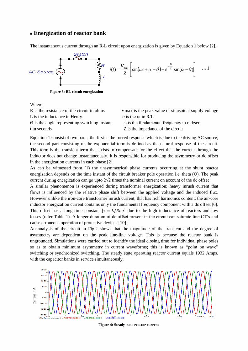
Energization of reactor bank
The instantaneous current through an R-L circuit upon energization is given by Equation 1 below [2].
)sin(sin)( max L
Rt
etZ
Vti
Where:
R is the resistance of the circuit in ohms Vmax is the peak value of sinusoidal supply voltage
L is the inductance in Henry. α is the ratio R/L
ϴ is the angle representing switching instant ω is the fundamental frequency in rad/sec
t in seconds Z is the impedance of the circuit
Equation 1 consist of two parts, the first is the forced response which is due to the driving AC source,
the second part consisting of the exponential term is defined as the natural response of the circuit.
This term is the transient term that exists to compensate for the effect that the current through the
inductor does not change instantaneously. It is responsible for producing the asymmetry or dc offset
in the energization currents in each phase [2].
As can be witnessed from (1) the unsymmetrical phase currents occurring at the shunt reactor
energization depends on the time instant of the circuit breaker pole operation i.e. theta (ϴ). The peak
current during energization can go upto 2√2 times the nominal current on account of the dc offset
A similar phenomenon is experienced during transformer energization; heavy inrush current that
flows is influenced by the relative phase shift between the applied voltage and the induced flux.
However unlike the iron-core transformer inrush current, that has rich harmonics content, the air-core
inductor energization current contains only the fundamental frequency component with a dc offset [6].
This offset has a long time constant due to the high inductance of reactors and low
losses (refer Table 1). A longer duration of dc offset present in the circuit can saturate line CT’s and
cause erroneous operation of protective devices [10].
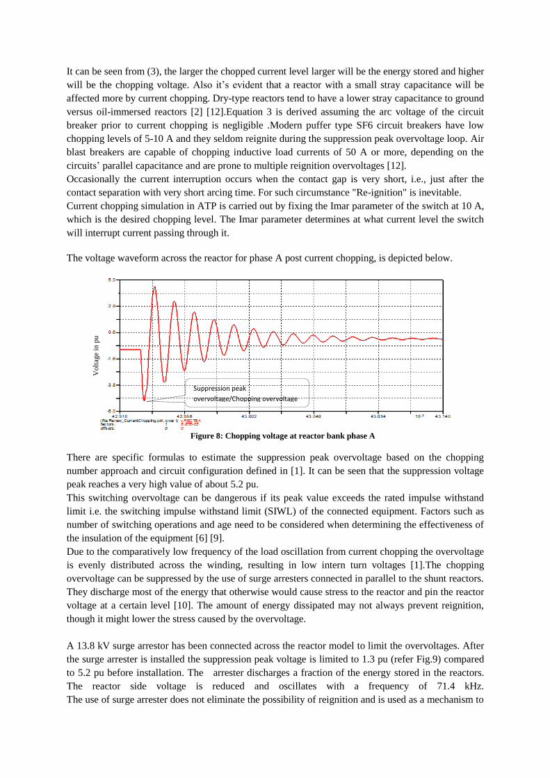
An analysis of the circuit in Fig.2 shows that the magnitude of the transient and the degree of
asymmetry are dependent on the peak line-line voltage. This is because the reactor bank is
ungrounded. Simulations were carried out to identify the ideal closing time for individual phase poles
so as to obtain minimum asymmetry in current waveforms; this is known as ―point on wave‖
switching or synchronized switching. The steady state operating reactor current equals 1932 Amps,
with the capacitor banks in service simultaneously.
Figure 4: Steady state reactor current
Cu
rren
t in
A
…. 1
Figure 3: RL circuit energization

The simulation of the shunt reactor energization was carried out for several closing times. Figure 5
shows the worst case energization current obtained, this occurs when the bank is energized near the
voltage zero crossing. The time controlled switches were instructed to close near the zero crossing of
the individual phase voltage. The maximum peak current for this case was found to be 4069.9 Amps,
with approximate duration of offset lasting 0.32 seconds. The percentage deviation from the steady
state value is 110.66 % which is as per expectations [6].
Figure 5: Worst case phase energization currents
The favourable instant for closing the switch was found to be near the peak of the supply voltage,
producing currents with minimum offset and smaller time decay constants. The time controlled
switches were instructed to switch in the reactors near the peak of each individual phase voltage. The
maximum peak current for this case was found to be 2535.2 Amps, with approximate duration of
offset lasting 0.15 seconds. The percentage deviation from the steady state value is 31.4 %.
Figure 6: Energization currents per phase with breaker closing near voltage peak
As can be seen in Figure 6 current asymmetry becomes smaller if the circuit breaker closes near the
maximal value of the power frequency line-to-ground voltage. The closing of the breaker poles at the
near peak value of voltage so as to limit the energization current might however generate switching
overvoltages due to contact gap pre-strike [10]. These voltages are equivalent to that which would
occur if a reignition occurred at 1 pu voltage across the switching device [1]. This can cause dielectric
stress to the reactor insulation. The capacitor bank being in service or de-energized has no effect on
the energization transients.
Cu
rren
t in
A
Cu
rren
t in
A

De-energization of reactor bank
The interruption of reactor current provokes excessive overvoltages particularly across the reactor and
the circuit breaker. The two types of overvoltages that are to be considered are due to the chopping
and the reignition. The phenomenon of current chopping or more commonly known as current
suppression results in chopping overvoltages. The overvoltages generated due to the reignition of the
arc inside the circuit breaker after initial current interruption lead to reignition overvoltages. The
reignition can lead to voltage escalation and several modes of oscillations in the inductive circuit [1]
[2].
1. Current Chopping and Chopping Overvoltage
Current chopping is caused by arc instability, which exhibits itself in the form of a negatively damped
current oscillation superimposed on the load current. The oscillation amplitude increases rapidly,
creating a current zero at which the circuit breaker usually interrupts [1] [4].Current chopping is often
observed when the no-load magnetizing current of transformer is being switched off or a shunt reactor
is disconnected. The tendency of the circuit-breaker to chop current is described by a chopping
number, which is a characteristic of the circuit breaker type [12]. The magnitude of the chopped
current is a function of chopping number and the total parallel capacitance seen by the circuit breaker
used to switch the shunt reactor. This parallel capacitance includes the source and load-side
capacitances and any grading capacitance across the circuit breaker. Higher chopping number
indicates greater tendency to chop current [12].
Figure 7: Current chopping and corresponding overvoltages a) Current through breaker b) Voltage across reactor
Pre-mature current
chopping before zero
crossing
Suppression peak
overvoltage
Recovery peak
overvoltage
Load Side
Oscillations
Vma
Vo
a)
b)

Figure 7 illustrates a simple example of current chopping; the current is pre-maturely interrupted
before its natural zero crossing. Since the circuit is primarily inductive in nature the voltage is near its
peak value when this happens. A significant amount of energy remains trapped on the reactor when
current chopping occurs. The electro-magnetic energy of the inductor is transferred into the
electrostatic energy of the capacitor and this energy oscillates between the reactor and stray
capacitances. The high di/dt associated with current chopping results in high induced voltage in the
inductive circuit [2]. In Figure 7, the first peak of the oscillation known as the chopping overvoltage
(Vma) has the same polarity as the system voltage at the time of interruption. The chopping
overvoltage or suppression peak overvoltage can be calculated from the energy balance equation,
given below [4].
From the energy balance equation__
Energy at current = Energy at chopping
Interruption Peak Voltage
Where,
C— Load side capacitance Ich— Chopped current level
V— Maximum chopping voltage L — Inductance of the reactor
Vo— Peak voltage across the inductor at the instant of current interruption
Re-arranging the equation the magnitude of the suppression peak overvoltage in pu of Vo is given by
the following equation
The second peak of the oscillation has the polarity opposite to that of the system voltage at the time of
interruption this is referred to as the recovery voltage overvoltage. The value of the recovery peak
voltage can equal the chopping overvoltage at times of negligible damping on the load side. These
load side oscillations will slowly decay in amplitude to zero. The load side oscillation produced is of
the order of few kHz for iron-core reactors and upto 100 kHz for air-core reactors [1] [6].
In the ungrounded wye connection when the first-phase clears the system turns in single phase mode
and the remaining two phases clear simultaneously. Prior to interruption the neutral of the reactor is at
ground potential due to the symmetry of the voltage and circuit, but as soon as the first pole clears the
neutral potential shifts with a transient oscillation towards a new value, which depends on the
grounding arrangement [1]. Also it was observed that for the disconnection of the shunt reactor bank
the chopping overvoltage for the first pole to clear was the maximum compared to the second and
third pole chopping overvoltage. See Table 2 for details.
Table 2: Comparison of chopping overvoltages for each individual phase pole clearing
Pole to Clear Peak Chopping Overvoltage in kV
A phase 58.383
B & C poles clear simultaneously for
your test system
B phase : 46.094
C phase : 46.190
b)
It can be seen from (3), the larger the chopped current level larger will be the energy stored and higher
will be the chopping voltage. Also it’s evident that a reactor with a small stray capacitance will be
affected more by current chopping. Dry-type reactors tend to have a lower stray capacitance to ground
versus oil-immersed reactors [2] [12].Equation 3 is derived assuming the arc voltage of the circuit
breaker prior to current chopping is negligible .Modern puffer type SF6 circuit breakers have low
chopping levels of 5-10 A and they seldom reignite during the suppression peak overvoltage loop. Air
blast breakers are capable of chopping inductive load currents of 50 A or more, depending on the
circuits’ parallel capacitance and are prone to multiple reignition overvoltages [12].
Occasionally the current interruption occurs when the contact gap is very short, i.e., just after the
contact separation with very short arcing time. For such circumstance "Re-ignition" is inevitable.
Current chopping simulation in ATP is carried out by fixing the Imar parameter of the switch at 10 A,
which is the desired chopping level. The Imar parameter determines at what current level the switch
will interrupt current passing through it.
The voltage waveform across the reactor for phase A post current chopping, is depicted below.
There are specific formulas to estimate the suppression peak overvoltage based on the chopping
number approach and circuit configuration defined in [1]. It can be seen that the suppression voltage
peak reaches a very high value of about 5.2 pu.
This switching overvoltage can be dangerous if its peak value exceeds the rated impulse withstand
limit i.e. the switching impulse withstand limit (SIWL) of the connected equipment. Factors such as
number of switching operations and age need to be considered when determining the effectiveness of
the insulation of the equipment [6] [9].
Due to the comparatively low frequency of the load oscillation from current chopping the overvoltage
is evenly distributed across the winding, resulting in low intern turn voltages [1].The chopping
overvoltage can be suppressed by the use of surge arresters connected in parallel to the shunt reactors.
They discharge most of the energy that otherwise would cause stress to the reactor and pin the reactor
voltage at a certain level [10]. The amount of energy dissipated may not always prevent reignition,
though it might lower the stress caused by the overvoltage.
A 13.8 kV surge arrestor has been connected across the reactor model to limit the overvoltages. After
the surge arrester is installed the suppression peak voltage is limited to 1.3 pu (refer Fig.9) compared
to 5.2 pu before installation. The arrester discharges a fraction of the energy stored in the reactors.
The reactor side voltage is reduced and oscillates with a frequency of 71.4 kHz.
The use of surge arrester does not eliminate the possibility of reignition and is used as a mechanism to
Suppression peak
overvoltage/Chopping overvoltage
Figure 8: Chopping voltage at reactor bank phase A
Volt
age
in p
u

reduce the peak values of the suppression and the recovery peak voltages generated due to current
chopping [1].
2. Reignition
A reignition occurs when a current interrupted at current zero re-establishes itself within one-eighth of
a power frequency cycle [14].Reignitions are provoked in a circuit breaker when the transient
recovery voltage (TRV) applied to the circuit breaker after current extinction is higher than the
dynamic voltage withstand capability of the circuit breaker dielectric during an opening operation.
Reignition occurs normally when arcing times are small and the contacts of the breaker have not yet
reached the full clearance required to withstand the voltage stress [12].
After the low inductive current interruption, the circuit breaker is stressed by a load side voltage
oscillation peak and the peak of the source side voltage, if a reignition occurs at this moment the load
side voltage will tend towards the source side voltage in the form of a high frequency oscillation
producing a reignition overvoltage (refer Figure 10) [1].This is generally the case during the second
peak of the load side oscillation, the recovery voltage peak. If a circuit breaker does not reignite
before or at this point then the interruption is
successful. If, however the instant of contact
parting is such that the contact gap does not yet
have sufficient dielectric strength or covers the
minimum arcing time, then a reignition will occur
as shown in Figure 10.
There are 4 different oscillation modes observed
during the interruption of current and reignition
process [1]. As discussed earlier the first is the load
side oscillation involving the reactor and its stray
capacitance, for an ungrounded reactor bank its
frequency of oscillation is given by
Typical range upto 30 kHz
Where,
L is the inductance of reactor per phase in Henry
C is the stray capacitance in Farad
Figure 9: Chopping voltage at reactor bank phase A after connection of surge
arrester
Volt
age
in p
u
Vma Vo
Load side
Oscillation Reignition at recovery
voltage peak
Second parallel
oscillation
Reignition
overvoltage
Figure 10: Reignition behaviour

The above equation is to derive the frequency of load oscillations produced for the first pole to clear
the frequency of oscillations produced by the 2 and 3 poles clearing is given by…
Post reignition, there is the ―first parallel‖ oscillation involving the discharge of Cp through the circuit
breaker and Lp (Refer Figure 1). For the case of tertiary connected reactor bank this oscillation is of
no significance. The ―second parallel‖ oscillation involves the capacitances Cs and CL and inductance
Lb, this is the reignition overvoltage oscillation with the frequency in the order of 50 to 1000 kHz.
The fourth is the ―main circuit‖ oscillation which is a special case involving the entire circuit in
Figure 1. Note for Cs >> CL no main circuit oscillation will occur [1].
Reignition overvoltages peak higher than the maximum chopping and with a high rate of change. The
surge arrester connected for the reactor bank protection though it is effective against the overvoltage
magnitude it is helpless against the steepness of the reignition overvoltages in most cases. These steep
overvoltages are unevenly distributed along the reactor winding stressing the insulation and causing
equipment breakdown [10].
The reignition simulation is carried out for the case study by re-closing the breaker at the peak of the
recovery voltage oscillation, after a current chopping has occurred this generates the highest
magnitude of reignition overvoltage.
Figure 11 shows that the reignition overvoltage oscillation reaches an abnormally high peak value of
8 pu for a 13.8 kV system base also the frequency of oscillations is observed to be 68 kHz. Figure 12
depicts the high frequency (71 kHz) and low magnitude inductive load current that is setup post the
first reignition ; the circuit breaker might interrupt this current again before or at the zero crossing and
give rise to yet another TRV across its poles. This leads to repetition of the cycle of events illustrated
above and multiple reignitions can occur. Factors influencing multiple reignitions have been covered
in detailed in [9].
Volt
age
in p
u
Figure 11: Reactor reignition transient voltage
Reignition overvoltage peak

High risk for
reignition
Target for
contact separation
Figure 14: Point-on-wave operation for preventing reignitions
.
The reignition overvoltage is clipped by the connected surge arrester however the frequency of the
load side oscillation remains the same. Overvoltages caused by reignition depend greatly on the
network configuration and on the circuit-breaker characteristics Apart from controlled switching,
there is little one can do to prevent reignition so the insulation should be designed with the worst case
in mind [10] [1].
Controlled Switching/Point on wave switching:
Various techniques have been developed to prevent the occurrence of reignitions in circuit breakers.
Earlier opening resistors were used on air
blast circuit breakers. Some SF6 circuit
breakers employ an arrester in parallel to
limit the chopping and reignition
overvoltages [16]. One of the latest
methods used and is applicable to the
shunt reactor switching is known as the
point-on-wave (POW) switching
generically called controlled switching.
Contact separation in this time range does not lead to reignition
Cu
rren
t in
Am
ps
Figure 12: Load current following reignition
Volt
age
in p
u
Figure 13: The reignition overvoltage suppression by surge arresters
Current

The strategy for controlled opening is to select arcing times long enough to avoid re-ignitions during
de-energizing of reactor banks. Uncontrolled de-energizing will, in a typical case, cause re-ignition in
at least one circuit breaker pole. Closing or opening commands to the circuit breaker are delayed in
such a way that making or contact separation will occur at the optimum time instant related to the
phase angle [10].For economic reasons, this is currently the preferred solution for high-voltage and
extra-high voltage shunt reactors.
The type of circuit breaker and circuit-breaker modifications are also major considerations, to employ
the POW scheme. Figure 14 illustrates a simple control mechanism employed in the POW method. It
mainly involves specifying the right time on the rising part of the current waveform for the contact to
start separating from each other. The use of surge arresters can further clip the overvoltage.
We have already simulated POW control logic using ATP time controlled switches to limit the
unsymmetrical inrush current in the first part of the study. Now we consider its effectiveness on our
model to limit transients associated with de- energization of reactor banks.
The de-energization of reactors in each phase was carried out at their respective current zero crossing.
Figure 15 shows the drastic reduction in the overvoltages when controlled switching is put in place.
Though switching at current zero crossing is the ideal situation to prevent overvoltages and reignition,
in practice, since these circuit breakers are mechanical switches, there is a lag in instant of zero
crossing and actual switching instant (possibly +/- 15 deg or more). Continuous monitoring of the line
voltages and currents on both ends of the breaker poles and advanced power electronics could be an
option to improve the efficiency of switching.
Conclusions:
Reactor bank switching imposes heavy duty on the circuit breaker and the connected equipment
during its energization and also during the de-energization of the bank.
In the case of the ungrounded reactor bank connected on the delta tertiary, the asymmetry due to dc
offsets during energization can be eliminated by closing the circuit breaker close to the maximal
value of the individual phase voltage.
It is concluded that the primary reasons for overvoltages during shunt reactor disconnection are
current chopping and reignitions, which occur due to non-ideal switching instances and are
influenced by the load side circuit and characteristics of the circuit breaker.
The suppression peak overvoltage is the highest in the case of the first pole to clear in comparison
with the following pole operations.
Volt
age
in p
u
Figure 15: Load Side oscillation at reactor bank phase
A

The smallest overvoltage magnitude is obtained if the reactor bank is disconnected at the natural
zero-crossing of the phase current.
A surge arrester is effective against protecting the reactor bank against the phase peak overvoltages
that occur during events like current chopping and reignition. However the frequency of the
oscillations remains unaltered.
Installation of surge arresters is more of a curative measure that comes into play post an
unfavourable switching event, but controlled switching is a preventive measure that is effective in
ensuring the non-occurrence of these undesired events.
References:
[1] IEEE Guide for the Application of Shunt Reactor Switching," IEEE Std C37.015-2009 (Revision
of IEEE Std C37.015-1993) , vol., no., pp.c1,53, Feb. 12 2010.
[2] A. Greenwood, Electrical Transients in Power Systems, 2nd ed., New York: Wiley, 1991.
[3] Hutahaean, R.P.; Sianipar, G., "Transient analysis of 150 kV shunt reactor at Bulukumba
Substation," Electrical Engineering and Informatics (ICEEI), 2011 International Conference on ,
vol., no., pp.1,6, 17-19 July 2011
[4] Chang, G.W.; Huang, H.-M.; Lai, J.H., "Modeling SF6 circuit breaker for shunt reactor switching
transient analysis," Power System Technology, 2004. PowerCon 2004. 2004 International
Conference on , vol.2, no., pp.1315,1320 Vol.2, 21-24 Nov. 2004.
[5] Munir, B.S.; Kadir, S.A., "Application of Surge Arrester on Vacuum Circuit Breaker," Power and
Energy Engineering Conference (APPEEC), 2012 Asia-Pacific, vol., no., pp.1,4, 27-29
March2012.
[6] IEEE Guide for the Protection of Shunt Reactors," IEEE Std C37.109-2006 (Revision of IEEE Std
C37.109-1988) , vol., no., pp.c1,55, April.20 2006.
[7] Hamid, H.A.; Harid, N.; Haddad, A., "Determination of transient overvoltages during shunt
reactor deenergization," Universities Power Engineering Conference (UPEC), 2009 Proceedings
of the 44th International , vol., no., pp.1,4, 1-4 Sept. 2009.
[8] Modelling of Restriking and Reignition Phenomena in Three-phase Capacitor and Shunt Reactor
Switching by Shui-cheong Kam School of Engineering Systems Queensland University of
Technology ,Brisbane, Australia.
[9] Ma, Z.; Bliss, C. A.; Penfold, A. R.; Harris, A. F W; Tennakoon, S.B., "An investigation of
transient overvoltage generation when switching high voltage shunt reactors by SF6 circuit
breaker," Power Delivery, IEEE Transactions on , vol.13, no.2, pp.472,479, Apr 1998.
[10] I. Uglesic et al., "Transients Due to Switching of 400 kV Shunt Reactor, in International
Conference on Power System Transients, 2001.

[11] HV shunt reactor secrets for protection engineers‖- Zoran Gajić, Birger Hillström, Fahrudin
Mekić
[12] IEEE Standard Requirements, Terminology, and Test Code for Shunt Reactors Rated Over 500
kVA," IEEE Std C57.21-2008 (Revision of IEEE Std C57.21-1990) , vol., no., pp.1,101, Aug. 1
2008 doi: 10.1109/IEEESTD.2008.4586406
[13] John Grainger and William Stevenson Jr., Power System Analysis, McGraw-Hill
Science/Engineering/Math; 1 edition (January 1, 1994)
[14] R. D. Garzon, High Voltage Circuit Breakers:Design and Applications: Marcel Dekker,Inc.,1996.
[15] A Circuit Breaker Model for Small Inductive Current Interruption by J.M Prosalidis, N.D
Hatziargyriou , B.C Papadias. www.ipst.org/techpapers/1 /I T aper 0 .pdf .
[16] Protection, Monitoring and Control of Shunt Reactors –CIGRE WG B5.37 2012


![Research on Stress Characteristics of Shunt Reactor ...PD-M4-8]_201.pdf · Research on Stress Characteristics of Shunt Reactor Considering Magnetic and Magnetostrictive Anisotropy](https://img.dokumen.tips/doc/110x75/5b1b41a67f8b9a32258e5113/research-on-stress-characteristics-of-shunt-reactor-pd-m4-8201pdf-research.jpg)


![PAPER 2003 03 en HV Shunt Reactor Secrets for Protection Engineers[1]](https://img.dokumen.tips/doc/110x75/55cf9a7c550346d033a1f731/paper-2003-03-en-hv-shunt-reactor-secrets-for-protection-engineers1.jpg)
