Embed Size (px)
Citation preview

PaceMaster Silver XRC
1
OWNER’S MANUAAerobics Inc., 34 Fairfield Place West Caldwell, NJ 0700
www.pacemaster.comPart # SILVER XRC
L 6, (973) 276-9700
Rev. 11/13/07

2
TABLE OF CONTENTS INTRODUCTION 3 IMPORTANT SAFETY INSTRUCTIONS 4 ASSEMBLY INSTRUCTIONS 5-17 Installation Requirements 5 Unpacking Your Recumbent 5 Tools Required for Assembly 5 Box Contents 6 Hardware Package Contents 7 Assembling Your Recumbent 8-17 THE PACEMASTER SILVER XRC BIKE CONTROL PANEL 18 OPERATING INSTRUCTIONS 18-31 Silver XRC Control Panel 18 Basic Operation 18-20 Button Functions 21 Manual Operation 22-23 Program Workouts 24-26 User Workout 27-28 Target Heart Rate Program 29-30 Hear Rate Recovery 31 Silver XRC Exploded Parts Diagram 32
PACEMASTER TECHNICAL SPECIFICATIONS 33

INTRODUCTION Congratulations and thank you for choosing PaceMaster – your partner in achieving your fitness goals and mastering your well-being. PaceMaster’s advanced digital technology allows your equipment to process information instantly, anticipating and adjusting to meet your needs. Think of it as your own personal trainer. PaceMaster’s superior components and US design ensure we produce equipment of the highest quality while also offering excellent value for your dollar. PaceMaster products have consistently received praise from a wide range of nationally recognized publications. To get the most from your PaceMaster, please read this owner’s manual carefully before starting to use this piece of exercise equipment. The manual contains important information about the assembly, operation and maintenance of the machine.
Please ensure you read and fully understand all safety information. DANGER, CAUTION, or
WARNING indicates important safety warnings throughout the manual. Failure to read and understand
these warnings may result in personal injury or damage to your Recumbent. Tip indicates a useful suggestion when installing, assembling or using your Recumbent. Please take the time to familiarize yourself with the range of functions available. This will help you work with your PaceMaster Recumbent for maximum efficiency to achieve your fitness goals and master your well-being. We wish you an enjoyable and rewarding partnership with your PaceMaster Recumbent.
The PaceMaster Silver XRC Bike is designed for home use only.
3
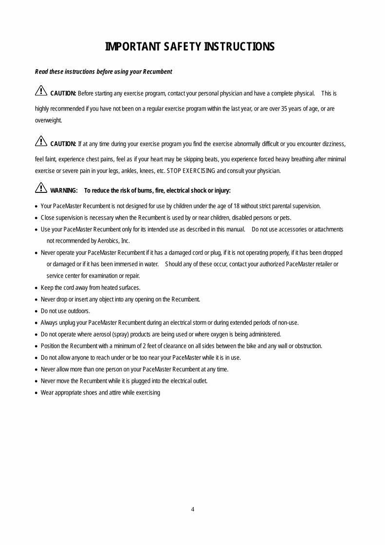
IMPORTANT SAFETY INSTRUCTIONS
Read these instructions before using your Recumbent
CAUTION: Before starting any exercise program, contact your personal physician and have a complete physical. This is
highly recommended if you have not been on a regular exercise program within the last year, or are over 35 years of age, or are
overweight.
CAUTION: If at any time during your exercise program you find the exercise abnormally difficult or you encounter dizziness,
feel faint, experience chest pains, feel as if your heart may be skipping beats, you experience forced heavy breathing after minimal
exercise or severe pain in your legs, ankles, knees, etc. STOP EXERCISING and consult your physician.
WARNING: To reduce the risk of burns, fire, electrical shock or injury:
• Your PaceMaster Recumbent is not designed for use by children under the age of 18 without strict parental supervision.
• Close supervision is necessary when the Recumbent is used by or near children, disabled persons or pets.
• Use your PaceMaster Recumbent only for its intended use as described in this manual. Do not use accessories or attachments
not recommended by Aerobics, Inc.
• Never operate your PaceMaster Recumbent if it has a damaged cord or plug, if it is not operating properly, if it has been dropped
or damaged or if it has been immersed in water. Should any of these occur, contact your authorized PaceMaster retailer or
service center for examination or repair.
• Keep the cord away from heated surfaces.
• Never drop or insert any object into any opening on the Recumbent.
• Do not use outdoors.
• Always unplug your PaceMaster Recumbent during an electrical storm or during extended periods of non-use.
• Do not operate where aerosol (spray) products are being used or where oxygen is being administered.
• Position the Recumbent with a minimum of 2 feet of clearance on all sides between the bike and any wall or obstruction.
• Do not allow anyone to reach under or be too near your PaceMaster while it is in use.
• Never allow more than one person on your PaceMaster Recumbent at any time.
• Never move the Recumbent while it is plugged into the electrical outlet.
• Wear appropriate shoes and attire while exercising
4

ASSEMBLY INSTRUCTIONS
Installation Requirements Your PaceMaster should be installed indoors on a flat, level surface near a 120Volt/ Grounded outlet. You must have a minimum
of 2 feet of clearance on all sides between the bike and any wall or obstruction.
TIP: If you are installing your PaceMaster on a carpeted surface, use a equipment mat or a scrap piece of carpet underneath the
Recumbent to avoid soiling of the carpet. Deep pile carpet is not recommended.
Unpacking Your Recumbent Exercise Bike On the next page is a listing of all the parts included in the box. Open the box and confirm that you have received all of the parts
indicated on page 6. If you are missing parts please contact your Authorized PaceMaster Dealer where you purchased your piece
of equipment.
Tools Required for Assembly (included) • Phillips head screwdriver
• 13 mm Wrench
• 15 mm Wrench
• 4 mm Allen Wrench
• 6 mm Allen Wrench
5
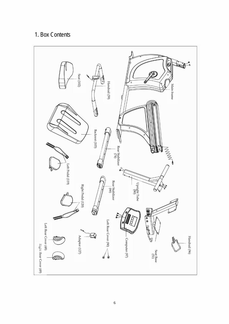
1. Box Contents
Handrail (59)
Seat (102)
Backrest (103)
Rear Stabilizer (74)
Rear lizer
Stabi(66)
Left Pedal (119) Right Pedal (120)
Right Rear Cover (49)
Left Rear Cover (48)
Adaptor (127)
Left Rear Cover (90)
Sese
at Ba(51)
Handrail (96)
Com
puter (97)
Upright Tube
(80)
Main fram
e
6
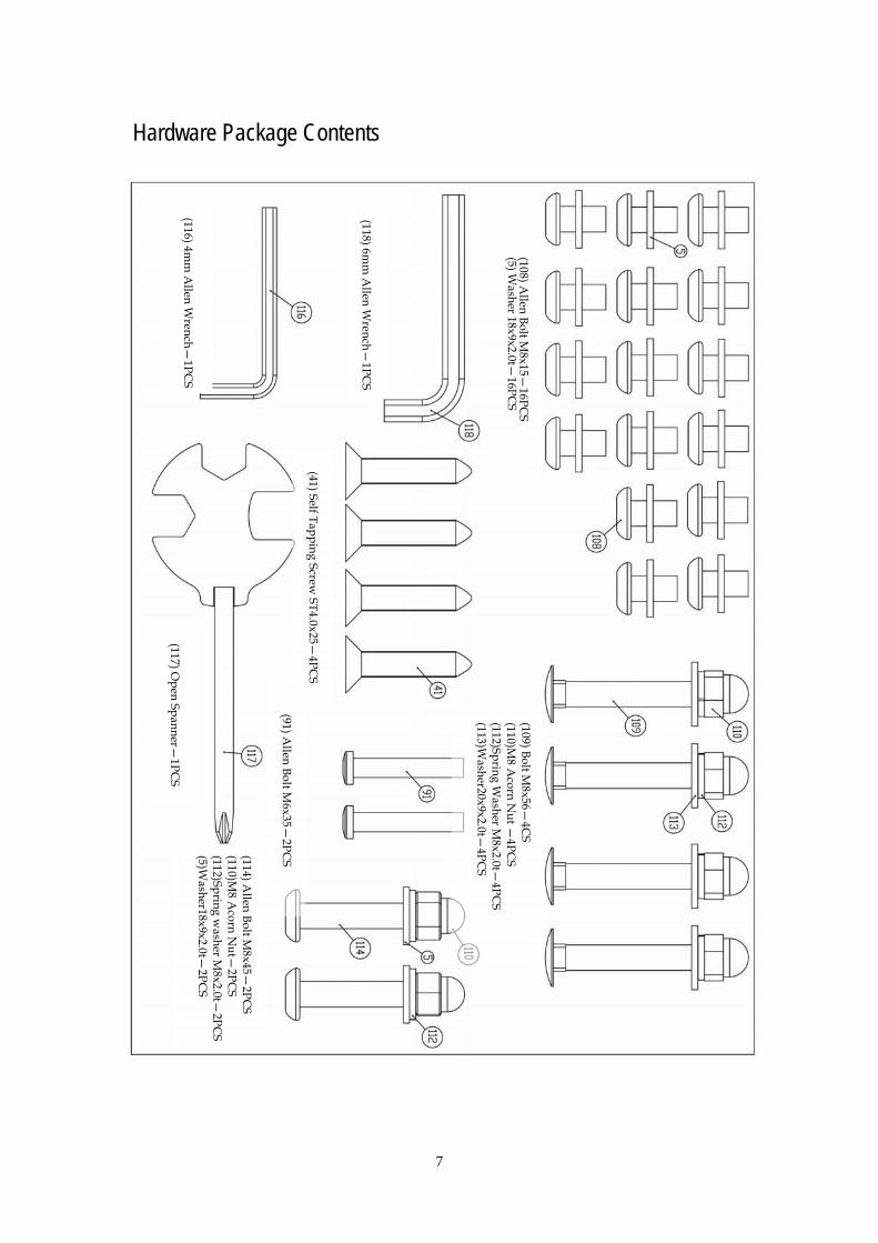
Hardware Package Contents
(117) Open Spanner—
1PCS
(109) Bolt M8х56—
4CS
(110)M8 A
corn Nut —
4PCS
(112)Spring Washer M
8x2.0t—4PC
S (113)W
asher20x9x2.0t—4PC
S
(114) Allen Bolt M
8х45—2PC
S (110)M
8 Acorn N
ut—2PC
S (112)Spring w
asher M8x2.0t—
2PCS
(5)Washer18x9x2.0t—
2PCS
(91) Allen Bolt M
6х35—2PC
S
(41) Self Tapping Screw ST4.0х25—
4PCS
(116) 4mm
Allen W
rench—1PC
S
(118) 6mm
Allen W
rench—1PC
S
(108) Allen Bolt M
8х15—16PC
(5) Washer 18х9х2.0t—
16PCS S
7

1. To assemble the Front Stabilizer
STEP 1A: As shown to the Right, attach the Front Stabilizer (66) to the Frame (1) with Bolts (109), Washers (113) (112) and Acorn Nuts (110), then tighten the nut with the included wrench (117) or a 13mm wrench or socket. Note: The front Stabilizer (66) is the one that has the wheels on it, AND the wheels must be towards the front.
Spring Washer M8х2.0t—2PCS (112)
Washer 20х9х2.0t—2PCS (113)
M8 Acorn Nut—2PCS (110)
Bolt M8х56—2PCS (109)
8

2. To assemble the Rear Stabilizer
STEP 2A: As shown to the Right, attach the Rear Stabilizer (74) to the Frame (1) with Bolts (109), Washers (113) (112) and Acorn Nuts (110), then tighten with the included wrench (117) or a 13mm wrench or socket.
Spring washer M8х2.0t—2PCS (112)
Washer 20х9х2.0t—2PCS (113)
M8 Acorn Nut—2PCS (110)
Bolt M8х56—2PCS (109)
9

3. To assemble the upright tube
STEP 3A: Connect the Contact Heart Rate Wires (17) & (83) then connect Wires (105)(122). STEP 3B: Slide the Upright (80) on to the main Frame (1), then secure the Upright to the Frame using 6 Bolts (108), 6 Washers (5) using a 6mm Allen wrench (151).
Washer 18х9х2.0t—6PCS(5)
Bolt M8х15—6PCS(108)
10

4. To assemble the Computer
A
Step 4A: Remove the 4 mounting screws (100) from theback of the Computer (97) with a Phillips head screw driver.
B
Step 4B: Connect the 2 pairs of contact heart rate wires (98) to (83) and (99) to (122). Then connect themain power wires shown in the center of Fig B to the right.Step 4C: Attach the Computer (97) to the Upright (80) with the 4 Phillips head screws (100) removed in Step A above. DO NOT PINCH the wires when securing the computer (97) to the mast (80).
C
11

5. To assemble the Seat, Handrail, Seat Sliding Base, Plastic Cushion and Rear Covers
Step 5A: Attach the Seat (102) to the Seat Base (51) with Bolts (108), Lock Washers (5) using the 6mm Allen Wrench (118).
A
Self Tapping Screw ST4.0x25—4PCS (41)
Allen Bolt
M6х35—2PCS (91)
Washer18x9x2.0t—6PCS (5)
Allen BoltM8x15—4PCS (108)
Allen Bolt
M8x45—2PCS (114)
M8 Acorn Nut—2PCS (110)
Spring Washer M8x2.0t—2PCS (112)
12
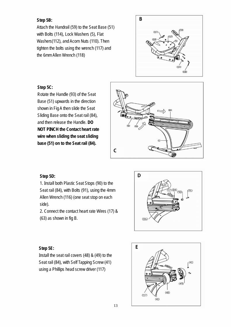
B
Step 5B: Attach the Handrail (59) to the Seat Base (51) with Bolts (114), Lock Washers (5), Flat Washers(112), and Acorn Nuts (110). Then tighten the bolts using the wrench (117) and the 6mm Allen Wrench (118)
C
Step 5C: Rotate the Handle (93) of the Seat Base (51) upwards in the direction shown in Fig A then slide the Seat Sliding Base onto the Seat rail (84), and then release the Handle. DO NOT PINCH the Contact heart rate wire when sliding the seat sliding base (51) on to the Seat rail (84).
D Step 5D: 1. Install both Plastic Seat Stops (90) to the Seat rail (84), with Bolts (91), using the 4mm Allen Wrench (116) (one seat stop on each side). 2. Connect the contact heart rate Wires (17) & (63) as shown in fig B.
EStep 5E:
Install the seat rail covers (48) & (49) to the Seat rail (84), with Self Tapping Screw (41) using a Phillips head screw driver (117)
13

6. To assemble the Backrest
Washer 18х9х2.0t—4PCS(5)
Bolt M8х15—4PCS(108)
STEP 6A: Install the Seat Back (103) to the Seat Base using Bolts (108), and Flat Washers (5), then tighten using the 6mm AllenWrench (118).
14
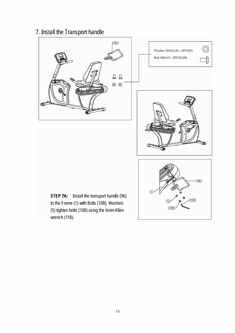
7. Install the Transport handle
STEP 7A: Install the transport handle (96) to the Frame (1) with Bolts (108), Washers (5) tighten bolts (108) using the 6mm Allen wrench (118).
Washer 18х9х2.0t—2PCS(5)
Bolt M8х15—2PCS(108)
15

8. Assemble and Install the Pedals
Step 8A: Install the toe straps on the pedals as shown in Fig A to the right.
B
B
A
Step 8B: The pedals are stamped on the threaded end of the axle with the letter “R” and “L” for Right and Left respectively. Right and Left sides are determined as seated on the recumbent bike. Install the Right pedal on the Right crank arm using the included wrench (117) or a 15 mm wrench. Install the Left pedal on the Left crank arm using the included wrench (117) or a 15 mm wrench. NOTE: The Left pedal is reverse thread (you must turn it counter-clockwise to tighten it).
16

9. Connecting the AC Adapter A
Step 9A: Plug the AC-AC Adapter (127) into the Power Jack (1) in the front of the recumbent as shown in Figure A to the right.
Step 9B: Plug the other end of the AC Adapter (127) into a 120 volt wall outlet then your Gold XRC is ready for use.
B
17

Operation Instructions Silver XRC Control Panel
START ENTERRESET RECOVERY
(PAUSE)
QUICKQUICK
(MODE)
LCD Display Screen
Buttons
Basic Operation Power On
Plug in the AC Adapter to your Silver XRC, then plug the AC adapter into a wall outlet (See step 11,
page 18). If your Silver XRC is already plugged in, press any button to turn on the display
After 5 min. of inactivity the display will enter sleep mode (shut off). To wake the display, press any
key.
Monitoring Heart Rate:
Contact Heart Rate – Your PaceMaster Silver XRC comes equipped with contact heart rate monitoring capability through contact heart rate grips. Your Heart Rate will be shown in the Pulse display. Wireless Heart Rate – Your PaceMaster Silver XRC equipped with a built in wireless heart rate receiver. If you have a Polar or Cardio Sport wireless chest strap and wear it according to the instruction that came with it while using your Silver XRC your heart rate will be displayed in the respective area on the display. A Wireless Chest Strap is NOT included with this product.
18

Quick Start Quick Start may be used at power-up and with all workout modes. Quick Start when used at power up will default manual mode. Note: Quick start will set work out parameters such as time, distance, calories to default values. Pause
Your workout can be paused by pressing START(PAUSE)
QUICKQUICK
. A flashing “P” will be displayed in upper left corner of panel
indicating workout is paused. Workout will resume when START(PAUSE)
QUICKQUICK
is pressed again. Pulse recovery
Press RECOVERY
to enter Pulse recovery program. Hold the hand pulse and in first 10 seconds, the computer will detect user heart rate. Then computer will count down 60 seconds automatically and display score by
A+,A-,B+,B-,C+,C-. A+ is the best and C- is the worst. If the computer cannot detect user heart rate in first 10
seconds, the computer will return to Pause mode. Press START(PAUSE)
QUICKQUICK
to enter workout mode. Press START(PAUSE)
QUICKQUICK
again andRESET
, the system will be reset. You can follow above steps to test Pulse recovery again.
Workout Selection There are 4 basic workout modes: Manual, Pre-program, User, Target HR
-- After power up press or to scroll flashing prompt to desired workout mode.
-- Press ENTER(MODE)
to select desired mode. --Quick Start can be initiated once mode is entered. Setting Workout Parameters After selecting desired workout mode: Manual, Program, User & Target HR, you may pre-set several workout parameters for desired results. WORKOUT PARAMETERS: RPM, SPEED, TIME, DISTANCE, WATTS, CALORIES, and PULSE Note: Some parameters are not adjustable in certain programs.
19

Once a program has been selected, pressing ENTER(MODE)
, will make “Time“ parameter flash.
Using you may select desired time value. Press ENTER(MODE)
to input value.
Flashing prompt will move to the next parameter. Continue use then ENTER(MODE)
until desired values are set.
Press START(PAUSE)
QUICKQUICK
to begin workout. On The Fly Changes
Parameters: Time, Distance, etc. maybe reset after program begins by pressingSTART(PAUSE)
QUICKQUICK
. When in pause mode,”
Time” will flash and can be used to adjust time. RESET
can be used to clear value. Press ENTER(MODE)
to move flashing prompt to next value. Repeat sequence for other parameters. Press START(PAUSE)
QUICKQUICK
to resume workout.
20
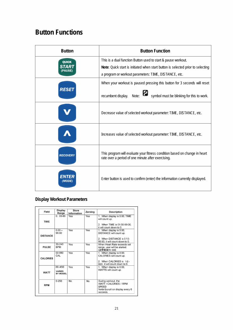
Button Functions
Button Button Function
START(PAUSE)
QUICKQUICK
This is a dual function Button used to start & pause workout.
Note: Quick start is initiated when start button is selected prior to selecting
a program or workout parameters: TIME, DISTANCE, etc.
RESET
When your workout is paused pressing this button for 3 seconds will reset
recumbent display. Note: symbol must be blinking for this to work.
Decrease value of selected workout parameter: TIME, DISTANCE, etc.
Increases value of selected workout parameter: TIME, DISTANCE, etc.
RECOVERY
This program will evaluate your fitness condition based on change in heart rate over a period of one minute after exercising.
ENTER(MODE)
Enter button is used to confirm (enter) the information currently displayed.
Display Workout Parameters
21

Manual Workout “Manual”
Manual is the default program at power-up. Press to adjust resistance levels. Setting Parameters for Manual
Turn on the power, press to select Manual model and press ENTER(MODE)
. “Time” will flash, and
can be adjusted using buttons. Press ENTER(MODE)
to save value & move to next parameter to be
adjusted. Continue through all desired parameters, press START(PAUSE)
QUICKQUICK
to begin workout. Notes: 1. Parameters can be reset at any time during workout, on the fly.
2. Some parameters are not adjustable in certain workout modes. See “Setting Workout Parameters” for further details.
“Manual” Operating Instructions
Turn on the power, press to select Manual model
“Manual” flashes START(PAUSE)
QUICKQUICK
Quick start with default values.
ENTER(MODE)
“Level” flashes Set your resistance level.
ENTER(MODE)
“Time” flashes If Time Goal is “0” value will count up.
ENTER(MODE)
“Distance” flashes If Distance Goal is “0” value will count up.
22
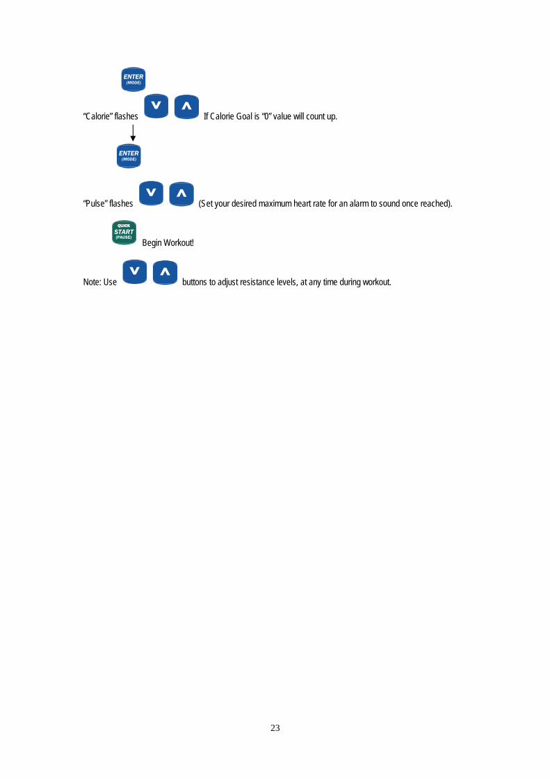
ENTER(MODE)
“Calorie” flashes If Calorie Goal is “0” value will count up. ENTER(MODE)
“Pulse” flashes (Set your desired maximum heart rate for an alarm to sound once reached).
START(PAUSE)
QUICKQUICK
Begin Workout!
Note: Use buttons to adjust resistance levels, at any time during workout.
23

Program Workouts” Program” There are12 program profiles ready for use. All program profiles have 16 levels of resistance that can be user adjusted.
Profile #1 Profile #2
Profile #3 Profile #4
Profile #6
Profile #5
Profile #7 Profile #8
24

Profile #9 Profile #10
Profile #11 Profile #12
Selecting a Program
Turn on the power, press to select program then press ENTER(MODE)
. Press to
select one of above 12 profile then press ENTER(MODE)
.
START(PAUSE)
QUICKQUICK
can be pressed to start workout if parameters will not be user set. Setting Parameters For Program Profile.
Select required program (P1-P12) then pressENTER(MODE)
. 1St parameter “Time” will flash so value can be adjusted
using
Press ENTER(MODE)
to save value & move to next parameter to be adjusted. Continue through all desired parameters,
press START(PAUSE)
QUICKQUICK
to begin workout.
Note: Use buttons to adjust resistance levels, at any time during workout.
25
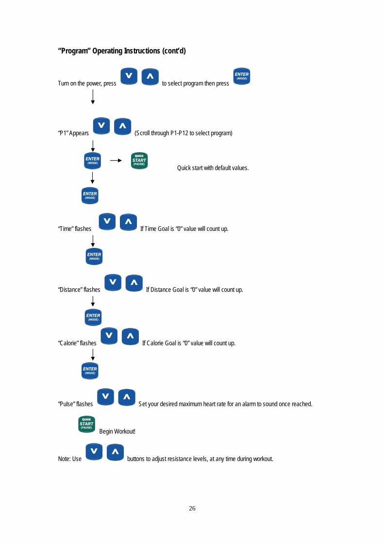
“Program” Operating Instructions (cont’d)
Turn on the power, press to select program then press ENTER(MODE)
“P1” Appears (Scroll through P1-P12 to select program)
ENTER(MODE)
START(PAUSE)
QUICKQUICK
Quick start with default values. ENTER(MODE)
“Time” flashes If Time Goal is “0” value will count up.
ENTER(MODE)
“Distance” flashes If Distance Goal is “0” value will count up.
ENTER(MODE)
“Calorie” flashes If Calorie Goal is “0” value will count up. ENTER(MODE)
“Pulse” flashes Set your desired maximum heart rate for an alarm to sound once reached.
START(PAUSE)
QUICKQUICK
Begin Workout!
Note: Use buttons to adjust resistance levels, at any time during workout.
26
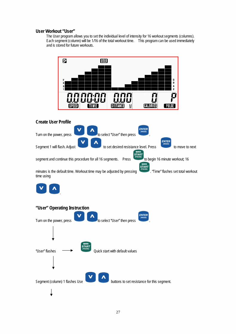
User Workout “User” The User program allows you to set the individual level of intensity for 16 workout segments (columns). Each segment (column) will be 1/16 of the total workout time. This program can be used immediately and is stored for future workouts.
Create User Profile
Turn on the power, press to select “User” then press ENTER(MODE)
.
Segment 1 will flash. Adjust to set desired resistance level. Press ENTER(MODE)
to move to next
segment and continue this procedure for all 16 segments. Press START(PAUSE)
QUICKQUICK
to begin 16 minute workout; 16
minutes is the default time. Workout time may be adjusted by pressing START(PAUSE)
QUICKQUICK
. “Time” flashes set total workout time using
. “User” Operating Instruction
Turn on the power, press to select “User” then press ENTER(MODE)
.
“User” flashes START(PAUSE)
QUICKQUICK
Quick start with default values
Segment (column) 1 flashes Use buttons to set resistance for this segment.
27

ENTER(MODE)
Segment (column) 2 flashes Use buttons to set resistance for this segment. Repeat this procedure for all 16 segments 16 segment.
START(PAUSE)
QUICKQUICK
Begin 16 minute workout! Adjusting Workout time (0-99 minutes.)
START(PAUSE)
QUICKQUICK
“Time” flashes If Time Goal is “0” value will count up.
ENTER(MODE)
“Distance” flashes If Distance Goal is “0” value will count up.
ENTER(MODE)
“Calorie” flashes If Calorie Goal is “0” value will count up. ENTER(MODE)
“Pulse” flashes (Set your desired maximum heart rate for an alarm to sound once reached).
START(PAUSE)
QUICKQUICK
Begin Workout!
Note: Use buttons to adjust resistance levels, at any time during workout.
28

Target Heart Rate Workout “Target HR” The Target Heart Rate workout allows user to maintain a specified heart rate throughout their workout. The Computer will adjust resistance to maintain target HR. User cannot adjust resistance levels manually. There are 4 selections for target PULSE: 55% = 55% of (220-AGE) 75% = 75 % (220-AGE) (See Examples below) 90% = 90% of (220-AGE) THR = Set by user
When target heart rate is achieved the computer will vary resistance to maintain the selected heart rate. Setting parameter for “ Target HR”
Turn on the power, press to select “Target HR” then press ENTER(MODE)
. “Age 30” will flash, press
to change age.(Range from 5 to 99). Press ENTER(MODE)
, 55% flashes and pressing
allows selection of 55%,75%, 90% and THR”. Press ENTER(MODE)
. Note: 55%- 90%, sets target HR pulse based on age and % of max HR selected. “THR” allows user to set target
heart rate.
If choosing “55%-90%” mode. Press ENTER(MODE)
to adjust “Time” using . Continue setting
desired parameters. Press START(PAUSE)
QUICKQUICK
to begin workout. When choosing “THR” mode “Pulse” will flashes “100.
Press to adjust pulse. Press ENTER(MODE)
then “Time” will flash use. Use to
enter value then press ENTER(MODE)
to continue with other parameters. Press START(PAUSE)
QUICKQUICK
to begin workout.
29

“Target HR” Operating Instructions
Turn on the power, press to select “Target HR” “HR Target” flashes
ENTER(MODE)
“Age 30” flashes . (To adjust user age.)
ENTER(MODE)
“55%” flashes, press . (To select: 55%, 75%, 90%, THR) 55% 75% 90% THR
ENTER(MODE)
ENTER(MODE)
ENTER(MODE)
ENTER(MODE)
“100” flashes Adjust target heart rate pulse.
ENTER(MODE)
“Time” flash.
Note: Continue setting remaining parameters. ENTER(MODE)
START(PAUSE)
QUICKQUICK
Note: Resistance levels cannot be adjusted by user in target HR
30

Heart Rate Recovery This feature will evaluate your fitness condition based on change in heart rate over a period of one minute. At the completion of this test a value (A+, A-, B+, B-, C+, C-) will be displayed (A+ is Best)
Press RECOVERY
to enter the recovery program, or press RESET
then RECOVERY
when flashing “P” is displayed, or stop your workout to enter the recovery program. In the first 10 seconds, the computer will detect your heart
rate (fig 1). Then computer will count down 60 seconds automatically (fig 2) and display your score (fig 3) (A+, A-,
B+, B-, C+, C-),A+ is the best. If the computer cannot detect user heart rate in first 10 seconds, the computer will
default to stand by mode.
Fig 1
Fig 2
Fig 3
31

Silver XRC 11/13/07
32
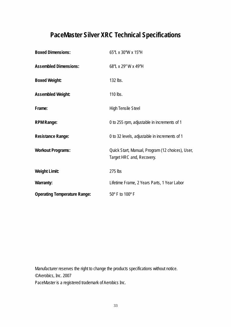
PaceMaster Silver XRC Technical Specifications Boxed Dimensions: 65”L x 30”W x 15”H Assembled Dimensions: 68”L x 29” W x 49”H Boxed Weight: 132 lbs. Assembled Weight: 110 lbs. Frame: High Tensile Steel
RPM Range: 0 to 255 rpm, adjustable in increments of 1
Resistance Range: 0 to 32 levels, adjustable in increments of 1 Workout Programs: Quick Start, Manual, Program (12 choices), User,
Target HRC and, Recovery. Weight Limit: 275 lbs Warranty: Lifetime Frame, 2 Years Parts, 1 Year Labor Operating Temperature Range: 50º F to 100º F Manufacturer reserves the right to change the products specifications without notice. © Aerobics, Inc. 2007 PaceMaster is a registered trademark of Aerobics Inc.
33