Embed Size (px)
Citation preview

Mot
herb
oard
P5GPL-X

i ii ii ii ii i
Copyright © 2005 ASUSTeK COMPUTER INC. All Rights Reserved.No part of this manual, including the products and software described in it, may be reproduced,transmitted, transcribed, stored in a retrieval system, or translated into any language in any formor by any means, except documentation kept by the purchaser for backup purposes, without theexpress written permission of ASUSTeK COMPUTER INC. (“ASUS”).
Product warranty or service will not be extended if: (1) the product is repaired, modified oraltered, unless such repair, modification of alteration is authorized in writing by ASUS; or (2)the serial number of the product is defaced or missing.
ASUS PROVIDES THIS MANUAL “AS IS” WITHOUT WARRANTY OF ANY KIND, EITHEREXPRESS OR IMPLIED, INCLUDING BUT NOT LIMITED TO THE IMPLIED WARRANTIESOR CONDITIONS OF MERCHANTABILITY OR FITNESS FOR A PARTICULAR PURPOSE.IN NO EVENT SHALL ASUS, ITS DIRECTORS, OFFICERS, EMPLOYEES OR AGENTS BELIABLE FOR ANY INDIRECT, SPECIAL, INCIDENTAL, OR CONSEQUENTIAL DAMAGES(INCLUDING DAMAGES FOR LOSS OF PROFITS, LOSS OF BUSINESS, LOSS OF USEOR DATA, INTERRUPTION OF BUSINESS AND THE LIKE), EVEN IF ASUS HAS BEENADVISED OF THE POSSIBILITY OF SUCH DAMAGES ARISING FROM ANY DEFECT ORERROR IN THIS MANUAL OR PRODUCT.
SPECIFICATIONS AND INFORMATION CONTAINED IN THIS MANUAL ARE FURNISHEDFOR INFORMATIONAL USE ONLY, AND ARE SUBJECT TO CHANGE AT ANY TIMEWITHOUT NOTICE, AND SHOULD NOT BE CONSTRUED AS A COMMITMENT BY ASUS.ASUS ASSUMES NO RESPONSIBILITY OR LIABILITY FOR ANY ERRORS ORINACCURACIES THAT MAY APPEAR IN THIS MANUAL, INCLUDING THE PRODUCTSAND SOFTWARE DESCRIBED IN IT.
Products and corporate names appearing in this manual may or may not be registeredtrademarks or copyrights of their respective companies, and are used only for identification orexplanation and to the owners’ benefit, without intent to infringe.
E2193E2193E2193E2193E2193
First Edit ionFirst Edit ionFirst Edit ionFirst Edit ionFirst Edit ionJuly 2005July 2005July 2005July 2005July 2005
i i ii i ii i ii i ii i i
Contents
Notices ................................................................................................ vi
Safety information ............................................................................. vii
About this guide ............................................................................... viii
Typography ......................................................................................... ix
P5GPL-X specifications summary ......................................................... x
Chapter 1: Product introductionChapter 1: Product introductionChapter 1: Product introductionChapter 1: Product introductionChapter 1: Product introduction
1.1 Welcome! .............................................................................. 1-2
1.2 Package contents ................................................................. 1-2
1.3 Special features .................................................................... 1-3
1.3.1 Product highlights ................................................... 1-3
1.3.2 Innovative ASUS features ....................................... 1-5
1.4 Before you proceed .............................................................. 1-6
1.5 Motherboard overview .......................................................... 1-7
1.5.1 Placement direction ................................................ 1-7
1.5.2 Screw holes ............................................................ 1-7
1.5.3 Motherboard layout ................................................ 1-8
1.6 Central Processing Unit (CPU) .............................................. 1-9
1.6.1 Installling the CPU ................................................... 1-9
1.6.2 Installling the CPU heatsink and fan ..................... 1-12
1.6.3 Uninstalling the CPU heatsink and fan .................. 1-14
1.7 System memory ................................................................. 1-16
1.7.1 Overview ............................................................... 1-16
1.7.2 Memory Configurations ......................................... 1-16
1.7.3 Installing a DIMM ................................................... 1-19
1.7.4 Removing a DIMM ................................................. 1-19
1.8 Expansion slots ................................................................... 1-20
1.8.1 Installing an expansion card .................................. 1-20
1.8.2 Configuring an expansion card .............................. 1-20
1.8.3 Interrupt assignments .......................................... 1-21
1.8.4 PCI slots ................................................................ 1-22
1.8.5 PCI Express x16 slot ............................................. 1-22
1.9 Jumpers .............................................................................. 1-23
1.10 Connectors ......................................................................... 1-26
1.10.1 Rear panel connectors .......................................... 1-26
1.10.2 Internal connectors ............................................... 1-27

i vi vi vi vi v
Contents
Chapter 2: BIOS setupChapter 2: BIOS setupChapter 2: BIOS setupChapter 2: BIOS setupChapter 2: BIOS setup
2.1 Managing and updating your BIOS ........................................ 2-2
2.1.1 Creating a bootable floppy disk .............................. 2-2
2.1.2 ASUS EZ Flash utility .............................................. 2-3
2.1.3 AFUDOS utility ........................................................ 2-4
2.1.4 ASUS CrashFree BIOS 2 utility ................................ 2-6
2.1.5 ASUS Update utility ................................................ 2-8
2.2 BIOS setup program ........................................................... 2-11
2.2.1 BIOS menu screen ................................................. 2-12
2.2.2 Menu bar ............................................................... 2-12
2.2.3 Navigation keys .................................................... 2-12
2.2.4 Menu items ........................................................... 2-13
2.2.5 Sub-menu items ................................................... 2-13
2.2.6 Configuration fields .............................................. 2-13
2.2.7 Pop-up window ..................................................... 2-13
2.2.8 Scroll bar .............................................................. 2-13
2.2.9 General help .......................................................... 2-13
2.3 Main menu .......................................................................... 2-14
2.3.1 System Time......................................................... 2-14
2.3.2 System Date ......................................................... 2-14
2.3.3 Legacy Diskette A ................................................ 2-14
2.3.4 Primary, Third and Fourth IDE Master/Slave ......... 2-15
2.3.5 IDE Configuration .................................................. 2-16
2.3.6 System Information .............................................. 2-18
2.4 Advanced menu .................................................................. 2-19
2.4.1 JumperFree Configuration .................................... 2-19
2.4.2 USB Configuration ................................................. 2-21
2.4.3 CPU Configuration ................................................. 2-22
2.4.4 Chipset ................................................................. 2-23
2.4.5 Onboard Devices Configuration ............................ 2-25
2.4.6 PCI PnP ................................................................. 2-26
2.5 Power menu ........................................................................ 2-27
2.5.1 Suspend Mode ...................................................... 2-27
2.5.2 Repost Video on S3 Resume ................................ 2-27
2.5.3 ACPI 2.0 Support .................................................. 2-27

vvvvv
Contents
2.5.4 ACPI APIC Support ................................................ 2-27
2.5.5 APM Configuration ................................................ 2-28
2.5.6 Hardware Monitor ................................................. 2-30
2.6 Boot menu .......................................................................... 2-31
2.6.1 Boot Device Priority .............................................. 2-32
2.6.2 Hard Disk Drives ................................................... 2-32
2.6.3 Boot Settings Configuration ................................. 2-32
2.6.4 Security ................................................................ 2-34
2.7 Exit menu ........................................................................... 2-36
Chapter 3: Software supportChapter 3: Software supportChapter 3: Software supportChapter 3: Software supportChapter 3: Software support
3.1 Installing an operating system ............................................. 3-2
3.2 Support CD information ........................................................ 3-2
3.2.1 Running the support CD ......................................... 3-2
3.2.2 Drivers menu .......................................................... 3-3
3.2.3 Utilities menu .......................................................... 3-4
3.2.4 ASUS Contact information ...................................... 3-5
Appendix:Appendix:Appendix:Appendix:Appendix: CPU featuresCPU featuresCPU featuresCPU featuresCPU features
A.1 Intel® EM64T ........................................................................ A-2
Using the Intel® EM64T feature ............................................ A-2
A.2 Enhanced Intel SpeedStep® Technology (EIST) .................... A-2
A.2.1 System requirements ............................................. A-2
A.2.2 Using the EIST ........................................................ A-3
A.3 Intel® Hyper-Threading Technology ...................................... A-4
Using the Hyper-Threading Technology ............................... A-4

v iv iv iv iv i
Notices
Federal Communications Commission StatementFederal Communications Commission StatementFederal Communications Commission StatementFederal Communications Commission StatementFederal Communications Commission Statement
This device complies with Part 15 of the FCC Rules. Operation is subject tothe following two conditions:
• This device may not cause harmful interference, and
• This device must accept any interference received including interferencethat may cause undesired operation.
This equipment has been tested and found to comply with the limits for aClass B digital device, pursuant to Part 15 of the FCC Rules. These limits aredesigned to provide reasonable protection against harmful interference in aresidential installation. This equipment generates, uses and can radiate radiofrequency energy and, if not installed and used in accordance withmanufacturer’s instructions, may cause harmful interference to radiocommunications. However, there is no guarantee that interference will notoccur in a particular installation. If this equipment does cause harmfulinterference to radio or television reception, which can be determined byturning the equipment off and on, the user is encouraged to try to correctthe interference by one or more of the following measures:
• Reorient or relocate the receiving antenna.
• Increase the separation between the equipment and receiver.
• Connect the equipment to an outlet on a circuit different from that towhich the receiver is connected.
• Consult the dealer or an experienced radio/TV technician for help.
Canadian Department of Communications StatementCanadian Department of Communications StatementCanadian Department of Communications StatementCanadian Department of Communications StatementCanadian Department of Communications Statement
This digital apparatus does not exceed the Class B limits for radio noiseemissions from digital apparatus set out in the Radio InterferenceRegulations of the Canadian Department of Communications.
This class B digital apparatus complies with CanadianThis class B digital apparatus complies with CanadianThis class B digital apparatus complies with CanadianThis class B digital apparatus complies with CanadianThis class B digital apparatus complies with CanadianICES-003.ICES-003.ICES-003.ICES-003.ICES-003.
The use of shielded cables for connection of the monitor to the graphicscard is required to assure compliance with FCC regulations. Changes ormodifications to this unit not expressly approved by the partyresponsible for compliance could void the user’s authority to operatethis equipment.

v i iv i iv i iv i iv i i
Safety information
Electrical safetyElectrical safetyElectrical safetyElectrical safetyElectrical safety
• To prevent electrical shock hazard, disconnect the power cable fromthe electrical outlet before relocating the system.
• When adding or removing devices to or from the system, ensure thatthe power cables for the devices are unplugged before the signal cablesare connected. If possible, disconnect all power cables from the existingsystem before you add a device.
• Before connecting or removing signal cables from the motherboard,ensure that all power cables are unplugged.
• Seek professional assistance before using an adapter or extension cord.These devices could interrupt the grounding circuit.
• Make sure that your power supply is set to the correct voltage in yourarea. If you are not sure about the voltage of the electrical outlet youare using, contact your local power company.
• If the power supply is broken, do not try to fix it by yourself. Contact aqualified service technician or your retailer.
Operation safetyOperation safetyOperation safetyOperation safetyOperation safety
• Before installing the motherboard and adding devices on it, carefully readall the manuals that came with the package.
• Before using the product, make sure all cables are correctly connectedand the power cables are not damaged. If you detect any damage,contact your dealer immediately.
• To avoid short circuits, keep paper clips, screws, and staples away fromconnectors, slots, sockets and circuitry.
• Avoid dust, humidity, and temperature extremes. Do not place theproduct in any area where it may become wet.
• Place the product on a stable surface.
• If you encounter technical problems with the product, contact a qualifiedservice technician or your retailer.
v i i iv i i iv i i iv i i iv i i i
About this guide
This user guide contains the information you need when installing andconfiguring the motherboard.
How this guide is organizedHow this guide is organizedHow this guide is organizedHow this guide is organizedHow this guide is organized
This manual contains the following parts:
••••• Chapter 1: Product introduct ionChapter 1: Product introduct ionChapter 1: Product introduct ionChapter 1: Product introduct ionChapter 1: Product introduct ion
This chapter describes the features of the motherboard and the newtechnology it supports. This chapter also lists the hardware setupprocedures that you have to perform when installing systemcomponents. It includes description of the jumpers and connectors onthe motherboard.
••••• Chapter 2: B IOS setupChapter 2: B IOS setupChapter 2: B IOS setupChapter 2: B IOS setupChapter 2: B IOS setup
This chapter tells how to change system settings through the BIOSSetup menus. Detailed descriptions of the BIOS parameters are alsoprovided.
••••• Chapter 3: Software supportChapter 3: Software supportChapter 3: Software supportChapter 3: Software supportChapter 3: Software support
This chapter describes the contents of the support CD that comeswith the motherboard package.
Where to find more informationWhere to find more informationWhere to find more informationWhere to find more informationWhere to find more information
Refer to the following sources for additional information and for productand software updates.
1 .1 .1 .1 .1 . ASUS webs itesASUS webs itesASUS webs itesASUS webs itesASUS webs ites
The ASUS website provides updated information on ASUS hardwareand software products. Refer to the ASUS contact information.
2 .2 .2 .2 .2 . Opt ional documentat ionOpt ional documentat ionOpt ional documentat ionOpt ional documentat ionOpt ional documentat ion
Your product package may include optional documentation, such aswarranty flyers, that may have been added by your dealer. Thesedocuments are not part of the standard package.
i xi xi xi xi x
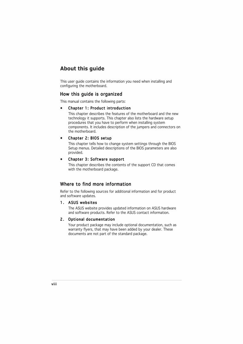
Conventions used in this guideConventions used in this guideConventions used in this guideConventions used in this guideConventions used in this guide
To make sure that you perform certain tasks properly, take note of thefollowing symbols used throughout this manual.
Typography
DANGER/WARNING: DANGER/WARNING: DANGER/WARNING: DANGER/WARNING: DANGER/WARNING: Information to prevent injury to yourselfwhen trying to complete a task.
CAUTION:CAUTION:CAUTION:CAUTION:CAUTION: Information to prevent damage to the componentswhen trying to complete a task.
NOTE: NOTE: NOTE: NOTE: NOTE: Tips and additional information to help you complete atask.
IMPORTANT: IMPORTANT: IMPORTANT: IMPORTANT: IMPORTANT: Instructions that you MUST follow to complete atask.
Bo l d t e x tBo l d t e x tBo l d t e x tBo l d t e x tBo l d t e x t Indicates a menu or an item to select
Italics Used to emphasize a word or a phrase
<Key> Keys enclosed in the less-than and greater-than sign meansthat you must press the enclosed key
Example: <Enter> means that you must press the Enter orReturn key
<Key1+Key2+Key3> If you must press two or more keys simultaneously, the
key names are linked with a plus sign (+)
Example: <Ctrl+Alt+D>
Command Means that you must type the command exactly as shown,
then supply the required item or value enclosed inbrackets
Example: At the DOS prompt, type the command line:
afudos /i[filename]
afudos /iP5GPLX.ROM

xxxxx
P5GPL-X specifications summary
(continued on the next page)
C P UC P UC P UC P UC P U
Ch ipsetCh ipsetCh ipsetCh ipsetCh ipset
Front S ide BusFront S ide BusFront S ide BusFront S ide BusFront S ide Bus
MemoryMemoryMemoryMemoryMemory
Expans ion s lotsExpans ion s lotsExpans ion s lotsExpans ion s lotsExpans ion s lots
Sto rageSto rageSto rageSto rageSto rage
Aud ioAud ioAud ioAud ioAud io
L A NL A NL A NL A NL A N
U S BU S BU S BU S BU S B
Spec ia l featuresSpec ia l featuresSpec ia l featuresSpec ia l featuresSpec ia l features
B IOS featuresB IOS featuresB IOS featuresB IOS featuresB IOS features
Rear Pane lRear Pane lRear Pane lRear Pane lRear Pane l
LGA775 socket for Intel® Pentium® 4/Celeron® processorCompatible with the Intel® PCG 04A and 04B processorsSupports Intel® Enhanced Intel SpeedStep Technology (EIST)Supports Intel® Enhanced Memory 64 Technology (EM64T)Supports Intel® Hyper-Threading Technology
Intel® 915PLIntel® ICH6
800/533 MHz
Dual-channel memory architecture2 x 184-pin DIMM sockets support up to 2GB of
unbufferred non-ECC 400/333 MHz DDR DIMMsASUS Hyper Path2
1 x PCI Express x16 slot1 x PCI Express x1 slot3 x PCI slots
1 x Ultra DMA 100/66/334 x Serial ATA
ADI AD1986A SoundMAX 6-channel audioSupport Jack Sensing and Enumeration TechnologyS/PDIF out interface
Intel® 82540EM Gigabit LAN controller
Supports up to 8 USB 2.0 ports
ASUS C.P.R. (CPU Parameter Recall)ASUS CPU Lock FreeASUS EZ FlashASUS CrashFree BIOS 2ASUS MyLogo™
4 Mb Flash ROM, AMI BIOS, PnP, DMI2.0, SM BIOS 2.3,WfM2.0
1 x Parallel port1 x LAN (RJ-45) port4 x USB 2.0 ports1 x Serial port (COM)1 x coaxial S/PDIF out1 x PS/2 keyboard port1 x PS/2 mouse port6-channel audio ports

x ix ix ix ix i
*Specifications are subject to change without notice.
P5GPL-X specifications summary
Overc lock ingOverc lock ingOverc lock ingOverc lock ingOverc lock ing
In te rna lI n te rna lI n te rna lI n te rna lI n te rna lconnectorsconnectorsconnectorsconnectorsconnectors
Ha rdwareHardwareHardwareHardwareHardwaremon i to r ingmon i to r ingmon i to r ingmon i to r ingmon i to r ing
Powe rPowe rPowe rPowe rPowe rRequ i rementRequ i rementRequ i rementRequ i rementRequ i rement
Form FactorForm FactorForm FactorForm FactorForm Factor
Support CDSupport CDSupport CDSupport CDSupport CDcontentscontentscontentscontentscontents
ASUS CPU Lock Free TechnologyASUS AI Overclocking (Intelligent CPU frequency tuner)CPU and Memory voltage adjustableSFS (Stepless Frequency Selection) from 100MHz up to400MHz at 1MHz incrementAdjustable FSB/DDR ratio. Fixed PCI/PCIe frequencies.ASUS C.P.R.(CPU Parameter Recall)
1 x IDE connector4 x SATA connector1 x floppy disk drive connector1 x CPU fan connector1 x Chassis fan connector1 x 24-pin ATX power connector1 x 4-pin ATX 12 V power connector2 x USB 2.0 connectors for 4 additional USB 2.0 ports1 x Optical drive audio connector1 x Front panel high-definition audio connector1 x S/PDIF out connector1 x GAME/MIDI connectorSystem panel connector
Super I/O integrated monitoring of CPU/chassis fan andCPU/MB temperature
ATX power supply (with 24-pin and 4-pin 12 V plugs)ATX 12 V 2.0 compliant
ATX form factor: 12 in x 7.2 in
Device driversASUS PC ProbeASUS Live Update utilityAnti-virus utility (OEM version)

x i ix i ix i ix i ix i i

ASUS P5GPL-XASUS P5GPL-XASUS P5GPL-XASUS P5GPL-XASUS P5GPL-X 1 - 11 - 11 - 11 - 11 - 1
1Productintroduction
This chapter describes the motherboardfeatures and the new technologiesit supports.

1 - 21 - 21 - 21 - 21 - 2 Chapter 1 : Product int roduct ionChapter 1 : Product int roduct ionChapter 1 : Product int roduct ionChapter 1 : Product int roduct ionChapter 1 : Product int roduct ion
1.1 Welcome!
Thank you for buying an ASUSThank you for buying an ASUSThank you for buying an ASUSThank you for buying an ASUSThank you for buying an ASUS®®®®® P5GPL-X motherboard! P5GPL-X motherboard! P5GPL-X motherboard! P5GPL-X motherboard! P5GPL-X motherboard!
The motherboard delivers a host of new features and latest technologies,making it another standout in the long line of ASUS quality motherboards!
Before you start installing the motherboard, and hardware devices on it,check the items in your package with the list below.
1.2 Package contents
Check your motherboard package for the following items.
MotherboardMotherboardMotherboardMotherboardMotherboard ASUS P5GPL-X motherboard
Cab lesCab lesCab lesCab lesCab les 1 x Serial ATA signal cables1 x Serial ATA power cables1 x Ultra DMA cables1 x Floppy disk drive cable
Accessor iesAccessor iesAccessor iesAccessor iesAccessor ies I/O shield
Appl icat ion CDsAppl icat ion CDsAppl icat ion CDsAppl icat ion CDsAppl icat ion CDs ASUS motherboard support CD
Documentat ionDocumentat ionDocumentat ionDocumentat ionDocumentat ion User guide
If any of the above items is damaged or missing, contact your retailer.

ASUS P5GPL-XASUS P5GPL-XASUS P5GPL-XASUS P5GPL-XASUS P5GPL-X 1 - 31 - 31 - 31 - 31 - 3
1.3 Special features
1.3.11.3.11.3.11.3.11.3.1 Product highlightsProduct highlightsProduct highlightsProduct highlightsProduct highlights
Latest processor technology Latest processor technology Latest processor technology Latest processor technology Latest processor technology
The motherboard comes with a 775-pin surface mount Land Grid Array(LGA) socket designed for the Intel® Pentium® 4 or Intel® Celeron®
processor in the 775-land package. The motherboard supports the Intel®
Pentium® 4 processor with 800/533 MHz Front Side Bus (FSB). Themotherboard also supports the Intel® Hyper-Threading Technology and isfully compatible with Intel® 04B and 04A processors. See page 1-9 fordetails.
IntelIntelIntelIntelIntel®®®®® 915PL 915PL 915PL 915PL 915PL
The Intel® 915PL chipset provides the interface for a processor in the775-land package with 533/800MHz front side bus (FSB), dual channelDDR at speeds of up to 400MHz, and PCI Express x16-lane port forgraphics card. The Intel® 915PL GMCH platform is compliant to the DirectMedia Interface (DMI) and supports the sixth generation I/O Controller Hub(ICH6).
IntelIntelIntelIntelIntel®®®®® EM64T EM64T EM64T EM64T EM64T
The motherboard supports Intel® Pentium® 4 processors with the Intel®
EM64T (Extended Memory 64 Technology). The Intel® EM64T featureallows your computer to run on 64-bit operating systems and access largeramounts of system memory for faster and more efficient computing. Seethe Appendix for details.
Enhanced Intel SpeedStepEnhanced Intel SpeedStepEnhanced Intel SpeedStepEnhanced Intel SpeedStepEnhanced Intel SpeedStep® Technology (EIST) Technology (EIST) Technology (EIST) Technology (EIST) Technology (EIST)
The Enhanced Intel SpeedStep® Technology (EIST) intelligently managesthe CPU resources by automatically adjusting the CPU voltage and corefrequency depending on the CPU loading and system speed or powerrequirement. See Appendix for details.
S/PDIF digital sound ready S/PDIF digital sound ready S/PDIF digital sound ready S/PDIF digital sound ready S/PDIF digital sound ready
The motherboard supports the S/PDIF Out function through the midboardS/PDIF interface. The S/PDIF technology turns your computer into a high-endentertainment system with digital connectivity to powerful audio and speakersystems. See pages 1-33 for details.
1 - 41 - 41 - 41 - 41 - 4 Chapter 1 : Product int roduct ionChapter 1 : Product int roduct ionChapter 1 : Product int roduct ionChapter 1 : Product int roduct ionChapter 1 : Product int roduct ion
Dual-channel DDR memory support Dual-channel DDR memory support Dual-channel DDR memory support Dual-channel DDR memory support Dual-channel DDR memory support
Employing the Double Data Rate (DDR) memory technology, themotherboard supports up to 2GB of system memory using DDR400/333DIMMs. The ultra-fast 400MHz memory bus delivers the required bandwidthfor the latest 3D graphics, multimedia, and Internet applications. See page1-16 for details.
PCI Express™ interfacePCI Express™ interfacePCI Express™ interfacePCI Express™ interfacePCI Express™ interface
The motherboard fully supports PCI Express, the latest I/O interconnecttechnology that speeds up the PCI bus. PCI Express features point-to-pointserial interconnections between devices and allows higher clockspeeds bycarrying data in packets. This high speed interface is software compatible withexisting PCI specifications. See page 1-22 for details.
Serial ATA technology Serial ATA technology Serial ATA technology Serial ATA technology Serial ATA technology
The motherboard supports the Serial ATA technology through the Serial ATAinterfaces and the Intel® ICH6. The SATA specification allows for thinner,more flexible cables with lower pin count, reduced voltage requirement, andup to 150 MB/s data transfer rate.
Gigabit LAN supportGigabit LAN supportGigabit LAN supportGigabit LAN supportGigabit LAN support
This motherboard comes with a Gigabit LAN controller to meet yourgrowing networking needs. The controller provides faster data bandwidthfor your Internet, LAN, and file sharing requirements. See pages 1-26.
6-channel audio 6-channel audio 6-channel audio 6-channel audio 6-channel audio
The motherboard comes with the ADI AD1986A audio CODEC that provides6-channel audio, audio jack-sensing and enumeration technology, andS/PDIF out support. See page 1-26 for details.
USB 2.0 technology USB 2.0 technology USB 2.0 technology USB 2.0 technology USB 2.0 technology
The motherboard implements the Universal Serial Bus (USB) 2.0specification, dramatically increasing the connection speed from the12 Mbps bandwidth on USB 1.1 to a fast 480 Mbps on USB 2.0. USB 2.0 isbackward compatible with USB 1.1. See pages 1-24, 1-27, 1-30 and 2-21for details.

ASUS P5GPL-XASUS P5GPL-XASUS P5GPL-XASUS P5GPL-XASUS P5GPL-X 1 - 51 - 51 - 51 - 51 - 5
1.3.21.3.21.3.21.3.21.3.2 Innovative ASUS featuresInnovative ASUS featuresInnovative ASUS featuresInnovative ASUS featuresInnovative ASUS features
CPU Lock Free CPU Lock Free CPU Lock Free CPU Lock Free CPU Lock Free
This feature allows you to adjust the CPU multiplier to 14x. Setting theappropriate BIOS setting automatically reduces the CPU multiplier value formore flexibility when increasing external FSB. See page 2-22 for details.
ASUS Hyper Path 2 technologyASUS Hyper Path 2 technologyASUS Hyper Path 2 technologyASUS Hyper Path 2 technologyASUS Hyper Path 2 technology
The ASUS Hyper Path 2 technology optimizes the full potential of the Intel®
chipset by shortening the latency time between the CPU and the systemmemory. See page 2-24 for details.
CrashFree BIOS 2 CrashFree BIOS 2 CrashFree BIOS 2 CrashFree BIOS 2 CrashFree BIOS 2
This feature allows you to restore the original BIOS data from the support CDin case when the BIOS codes and data are corrupted. This protectioneliminates the need to buy a replacement ROM chip. See details on page 2-6.
ASUS Q-Fan technology ASUS Q-Fan technology ASUS Q-Fan technology ASUS Q-Fan technology ASUS Q-Fan technology
The ASUS Q-Fan technology smartly adjusts the CPU fan speed accordingto the system loading to ensure quiet, cool, and efficient operation. Seepage 2-30 for details.
ASUS MyLogo™ ASUS MyLogo™ ASUS MyLogo™ ASUS MyLogo™ ASUS MyLogo™
This new feature present in the motherboard allows you to personalize andadd style to your system with customizable boot logos. See page 2-33.
C.P.R. (CPU Parameter Recall) C.P.R. (CPU Parameter Recall) C.P.R. (CPU Parameter Recall) C.P.R. (CPU Parameter Recall) C.P.R. (CPU Parameter Recall)
The C.P.R. feature of the motherboard BIOS allows automatic re-setting tothe BIOS default settings in case the system hangs due to overclocking.When the system hangs due to overclocking, C.P.R. eliminates the need toopen the system chassis and clear the RTC data. Simply shut down andreboot the system, and the BIOS automatically restores the CPU defaultsetting for each parameter.
Temperature, fan, and voltage monitoringTemperature, fan, and voltage monitoringTemperature, fan, and voltage monitoringTemperature, fan, and voltage monitoringTemperature, fan, and voltage monitoring
The CPU temperature is monitored by the Winbond Super I/O to preventoverheating and damage. The system fan rotation per minute (RPM) ismonitored for timely failure detection. The Winbond Super I/O monitors thevoltage levels to ensure stable supply of current for critical components.

1 - 61 - 61 - 61 - 61 - 6 Chapter 1 : Product int roduct ionChapter 1 : Product int roduct ionChapter 1 : Product int roduct ionChapter 1 : Product int roduct ionChapter 1 : Product int roduct ion
Onboard LEDOnboard LEDOnboard LEDOnboard LEDOnboard LED
The motherboard comes with a standby power LED that lights up toindicate that the system is ON, in sleep mode, or in soft-off mode.This is a reminder that you should shut down the system and unplugthe power cable before removing or plugging in any motherboardcomponent. The illustration below shows the location of the onboardLED.
1.4 Before you proceed
Take note of the following precautions before you install motherboardcomponents or change any motherboard settings.
• Unplug the power cord from the wall socket before touching anycomponent.
• Use a grounded wrist strap or touch a safely grounded object or toa metal object, such as the power supply case, before handlingcomponents to avoid damaging them due to static electricity
• Hold components by the edges to avoid touching the ICs on them.
• Whenever you uninstall any component, place it on a groundedantistatic pad or in the bag that came with the component.
• Before you insta l l o r remove any component , ensureBefore you insta l l o r remove any component , ensureBefore you insta l l o r remove any component , ensureBefore you insta l l o r remove any component , ensureBefore you insta l l o r remove any component , ensurethat the ATX power supp ly i s sw itched of f or thethat the ATX power supp ly i s sw itched of f or thethat the ATX power supp ly i s sw itched of f or thethat the ATX power supp ly i s sw itched of f or thethat the ATX power supp ly i s sw itched of f or thepower cord i s detached f rom the power supp ly . power cord i s detached f rom the power supp ly . power cord i s detached f rom the power supp ly . power cord i s detached f rom the power supp ly . power cord i s detached f rom the power supp ly . Failureto do so may cause severe damage to the motherboard, peripherals,and/or components.
P5GPL-X
®
P5GPL-X Onboard LED
SB_PWR
ONStandbyPower
OFFPowered
Off

ASUS P5GPL-XASUS P5GPL-XASUS P5GPL-XASUS P5GPL-XASUS P5GPL-X 1 - 71 - 71 - 71 - 71 - 7
1.5 Motherboard overview
Before you install the motherboard, study the configuration of your chassisto ensure that the motherboard fits into it.
Make sure to unplug the power cord before installing or removing themotherboard. Failure to do so can cause you physical injury and damagemotherboard components.
Do not overtighten the screws! Doing so can damage the motherboard.
1.5.11.5.11.5.11.5.11.5.1 Placement directionPlacement directionPlacement directionPlacement directionPlacement direction
When installing the motherboard, make sure that you place it into thechassis in the correct orientation. The edge with external ports goes to therear part of the chassis as indicated in the image below.
1.5.21.5.21.5.21.5.21.5.2 Screw holesScrew holesScrew holesScrew holesScrew holes
Place seven (7) screws into the holes indicated by circles to secure themotherboard to the chassis.
P l ace th i s s i de towa rdsP l ace th i s s i de towa rdsP l ace th i s s i de towa rdsP l ace th i s s i de towa rdsP l ace th i s s i de towa rdsthe r ea r o f the chass i sthe r ea r o f the chass i sthe r ea r o f the chass i sthe r ea r o f the chass i sthe r ea r o f the chass i s
P5GPL-X
®

1 - 81 - 81 - 81 - 81 - 8 Chapter 1 : Product int roduct ionChapter 1 : Product int roduct ionChapter 1 : Product int roduct ionChapter 1 : Product int roduct ionChapter 1 : Product int roduct ion
1.5.31.5.31.5.31.5.31.5.3 Motherboard layoutMotherboard layoutMotherboard layoutMotherboard layoutMotherboard layout
P5GPL-X
CR2032 3VLithium Cell
CMOS Power
CD
Su
pe
rI/
O
Inte
l FW
H4M
b
ATX12V
FLOPPY
AAFP
DD
R D
IMM
_A1
(64
bit,1
84-p
in m
odul
e)
KBPWR
SB_PWR
USBPW1
18.2cm (7.2in)
30.5
cm (
12.0
in)
PANEL
CHASSIS
USB78USB56
USBPW2CLRTC
CHA_FAN
PCI1
Intel®
ICH6
DD
R D
IMM
_B1
(64
bit,1
84-p
in m
odul
e)
CPU_FAN
AD1986A
PCI2
PCI3
SPDIF_OUT
IntelRC82540
PS/2KBMST: MouseB: Keyboard
Below:Mic In
Center:Line Out
Top:Line In
F_USB12
LAN_USB34
PCIEX1_1
PCIEX16
EAT
XP
WR
LGA775
PAR
AL
LE
L P
OR
T
COM1
SPDIF_O
GAME
®
SA
TA4
PR
I_ID
E
SA
TA3
SA
TA1
SA
TA2
Intel®
915PL

ASUS P5GPL-XASUS P5GPL-XASUS P5GPL-XASUS P5GPL-XASUS P5GPL-X 1 - 91 - 91 - 91 - 91 - 9
1.6.11.6.11.6.11.6.11.6.1 Installl ing the CPUInstalll ing the CPUInstalll ing the CPUInstalll ing the CPUInstalll ing the CPU
To install a CPU:
1. Locate the CPU socket on the motherboard.
1.6 Central Processing Unit (CPU)
The motherboard comes with a surface mount LGA775 socket designed forthe Intel® Pentium® 4 processor in the 775-land package.
• Your boxed Intel® Pentium® 4 LGA775 processor package shouldcome with installation instructions for the CPU, fan and heatsinkassembly. If the instructions in this section do not match the CPUdocumentation, follow the latter.
• Upon purchase of the motherboard, make sure that the PnP cap ison the socket and the socket pins are not bent. Contact yourretailer immediately if the PnP cap is missing, or if you see anydamage to the PnP cap/socket pins/motherboard components.ASUS will shoulder the cost of repair only if the damage is shipment/transit-related.
• Keep the cap after installing the motherboard. ASUS will processReturn Merchandise Authorization (RMA) requests only if themotherboard comes with the cap on the LGA775 socket.
• The product warranty does not cover damage to the socket pinsresulting from incorrect CPU installation/removal, or misplacement/loss/incorrect removal of the PnP cap.
Before installing the CPU, make sure that the socket box is facingtowards you and the load lever is on your left.
P5GPL-X
®
P5GPL-X CPU Socket 775
1 -101 -101 -101 -101 -10 Chapter 1 : Product int roduct ionChapter 1 : Product int roduct ionChapter 1 : Product int roduct ionChapter 1 : Product int roduct ionChapter 1 : Product int roduct ion
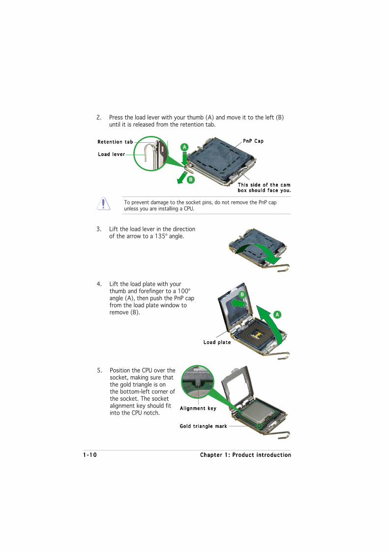
3. Lift the load lever in the directionof the arrow to a 135º angle.
4. Lift the load plate with yourthumb and forefinger to a 100ºangle (A), then push the PnP capfrom the load plate window toremove (B).
To prevent damage to the socket pins, do not remove the PnP capunless you are installing a CPU.
5. Position the CPU over thesocket, making sure thatthe gold triangle is onthe bottom-left corner ofthe socket. The socketalignment key should fitinto the CPU notch.
2. Press the load lever with your thumb (A) and move it to the left (B)until it is released from the retention tab.
Re ten t i on t abRe ten t i on t abRe ten t i on t abRe ten t i on t abRe ten t i on t ab
Load l e ve rLoad l e ve rLoad l e ve rLoad l e ve rLoad l e ve r
Th i s s i de o f the camTh i s s i de o f the camTh i s s i de o f the camTh i s s i de o f the camTh i s s i de o f the cambox shou ld f ace you .box shou ld f ace you .box shou ld f ace you .box shou ld f ace you .box shou ld f ace you .
P n P C a pP n P C a pP n P C a pP n P C a pP n P C a p
A
B
Load p l a t eLoad p l a t eLoad p l a t eLoad p l a t eLoad p l a t e
A
B
A l i gnment keyA l i gnment keyA l i gnment keyA l i gnment keyA l i gnment key
Go ld t r i ang l e ma rkGo ld t r i ang l e ma rkGo ld t r i ang l e ma rkGo ld t r i ang l e ma rkGo ld t r i ang l e ma rk

ASUS P5GPL-XASUS P5GPL-XASUS P5GPL-XASUS P5GPL-XASUS P5GPL-X 1 -111 -111 -111 -111 -11
The CPU fits in only one correct orientation. DO NOT force the CPU intothe socket to prevent bending the connectors on the socket anddamaging the CPU!
6. Close the load plate (A), thenpush the load lever (B) until itsnaps into the retention tab.
A
B
1 -121 -121 -121 -121 -12 Chapter 1 : Product int roduct ionChapter 1 : Product int roduct ionChapter 1 : Product int roduct ionChapter 1 : Product int roduct ionChapter 1 : Product int roduct ion
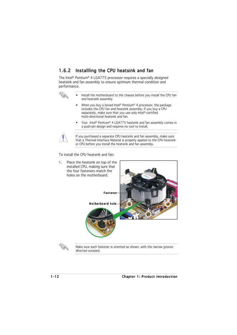
1.6.21.6.21.6.21.6.21.6.2 Installling the CPU heatsink and fanInstallling the CPU heatsink and fanInstallling the CPU heatsink and fanInstallling the CPU heatsink and fanInstallling the CPU heatsink and fan
The Intel® Pentium® 4 LGA775 processor requires a specially designedheatsink and fan assembly to ensure optimum thermal condition andperformance.
• Install the motherboard to the chassis before you install the CPU fanand heatsink assembly
• When you buy a boxed Intel® Pentium® 4 processor, the packageincludes the CPU fan and heatsink assembly. If you buy a CPUseparately, make sure that you use only Intel®-certifiedmulti-directional heatsink and fan.
• Your Intel® Pentium® 4 LGA775 heatsink and fan assembly comes ina push-pin design and requires no tool to install.
If you purchased a separate CPU heatsink and fan assembly, make surethat a Thermal Interface Material is properly applied to the CPU heatsinkor CPU before you install the heatsink and fan assembly.
To install the CPU heatsink and fan:
1. Place the heatsink on top of theinstalled CPU, making sure thatthe four fasteners match theholes on the motherboard.
Fa s t ene rF a s t ene rF a s t ene rF a s t ene rF a s t ene r
Mothe rboa rd ho l eMothe rboa rd ho l eMothe rboa rd ho l eMothe rboa rd ho l eMothe rboa rd ho l e
Make sure each fastener is oriented as shown, with the narrow groovedirected outward.

ASUS P5GPL-XASUS P5GPL-XASUS P5GPL-XASUS P5GPL-XASUS P5GPL-X 1 -131 -131 -131 -131 -13
Do not forget to connect the CPU fan connector! Hardware monitoringerrors can occur if you fail to plug this connector.
3. When the fan and heatsink assembly is in place, connect the CPU fancable to the connector on the motherboard labeled CPU_FAN.
2. Push down two fasteners at atime in a diagonal sequence tosecure the heatsink and fanassembly in place.
A
A B
B
B
B
AA
P5GPL-X
®
P5GPL-X CPU fan connector
CPU_FAN
GN
DC
PU
FA
N P
WR
CP
U F
AN
INC
PU
FA
N P
WM
1 -141 -141 -141 -141 -14 Chapter 1 : Product int roduct ionChapter 1 : Product int roduct ionChapter 1 : Product int roduct ionChapter 1 : Product int roduct ionChapter 1 : Product int roduct ion
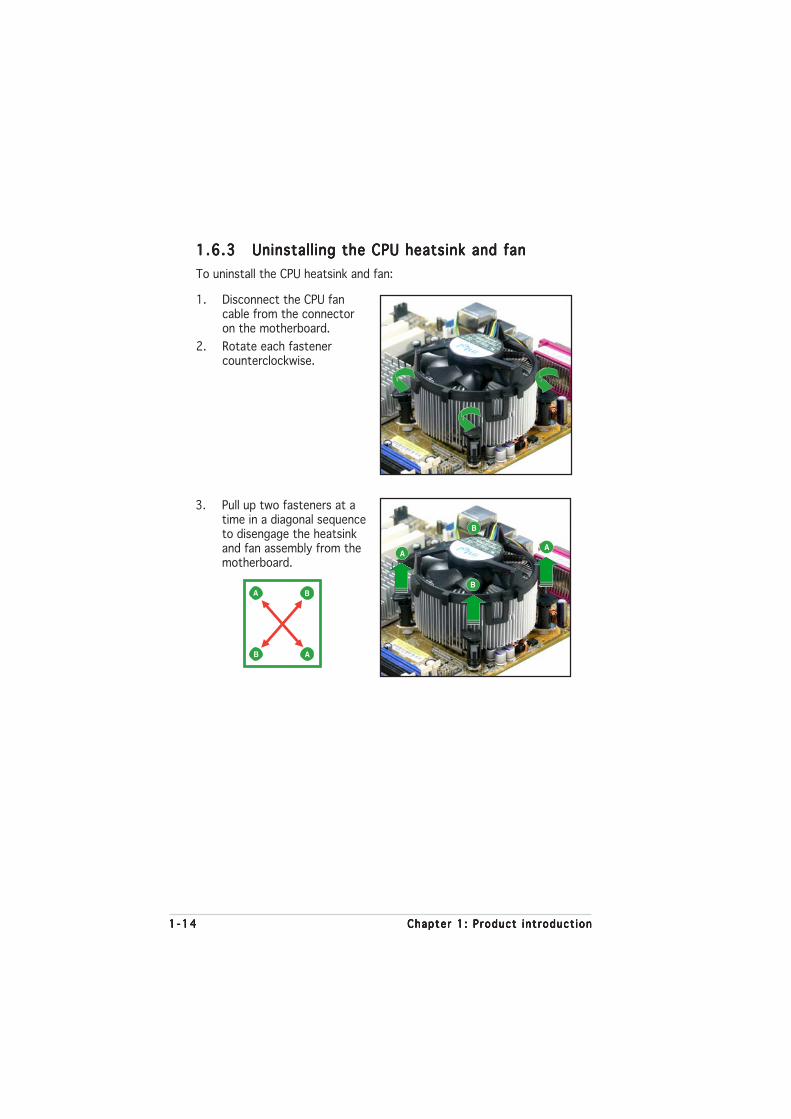
1.6.31.6.31.6.31.6.31.6.3 Uninstalling the CPU heatsink and fanUninstalling the CPU heatsink and fanUninstalling the CPU heatsink and fanUninstalling the CPU heatsink and fanUninstalling the CPU heatsink and fan
To uninstall the CPU heatsink and fan:
1. Disconnect the CPU fancable from the connectoron the motherboard.
2. Rotate each fastenercounterclockwise.
3. Pull up two fasteners at atime in a diagonal sequenceto disengage the heatsinkand fan assembly from themotherboard.
A
A B
B
B
B
AA

ASUS P5GPL-XASUS P5GPL-XASUS P5GPL-XASUS P5GPL-XASUS P5GPL-X 1 -151 -151 -151 -151 -15
4. Remove the heatsink and fanassembly from themotherboard.
5. Rotate each fastenerclockwise to reset theorientation.
When reset, each fastenershould be oriented asshown, with the narrowgroove directed outward.

1 -161 -161 -161 -161 -16 Chapter 1 : Product int roduct ionChapter 1 : Product int roduct ionChapter 1 : Product int roduct ionChapter 1 : Product int roduct ionChapter 1 : Product int roduct ion
1.7 System memory
1.7.11.7.11.7.11.7.11.7.1 OverviewOverviewOverviewOverviewOverview
The motherboard comes with two 184-pin Double Data Rate (DDR) DualInline Memory Modules (DIMM) sockets.
The following figure illustrates the location of the sockets:
1.7.21.7.21.7.21.7.21.7.2 Memory ConfigurationsMemory ConfigurationsMemory ConfigurationsMemory ConfigurationsMemory Configurations
You may install 256 MB, 512 MB and 1 GB unbuffered non-ECC DDR DIMMsinto the DIMM sockets using the memory configurations in this section.
• Installing DDR DIMMs other than the recommended configurationsmay cause memory sizing error or system boot failure. Use any ofthe recommended configurations in Table 1.
• Always install DIMMs with the same CAS latency. For optimumcompatibility, it is recommended that you obtain memory modulesfrom the same vendor. See Table 2 for qualified DDR DIMMs.
• Due to chipset limitation, DIMM modules with 128 Mb memory chipsor double-sided x16 memory chips are not supported in thismotherboard.
P5GPL-X
®
P5GPL-X 184-pin DDR DIMM sockets
DIM
M_A
1
DIM
M_B
1
ASUS P5GPL-XASUS P5GPL-XASUS P5GPL-XASUS P5GPL-XASUS P5GPL-X 1 -171 -171 -171 -171 -17
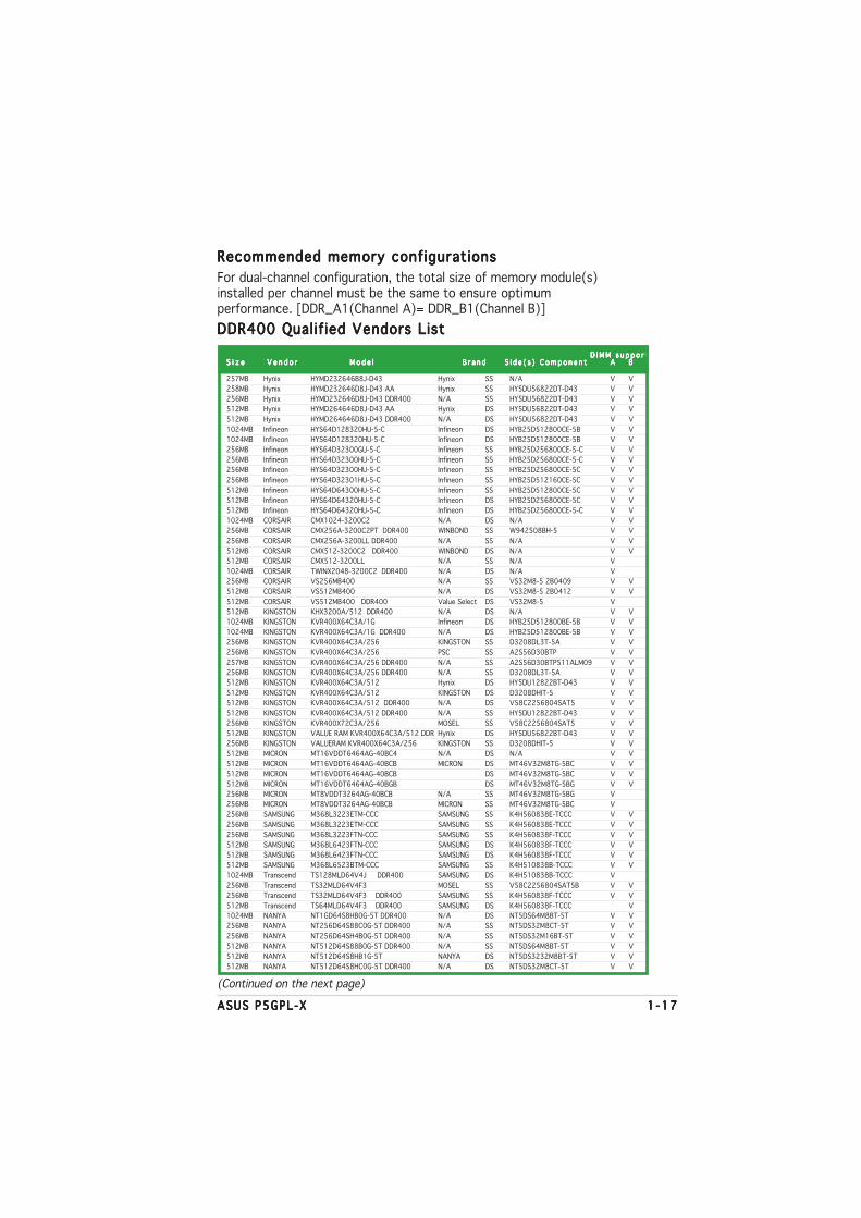
Recommended memory configurationsRecommended memory configurationsRecommended memory configurationsRecommended memory configurationsRecommended memory configurations
For dual-channel configuration, the total size of memory module(s)installed per channel must be the same to ensure optimumperformance. [DDR_A1(Channel A)= DDR_B1(Channel B)]
DDR400 Qualif ied Vendors ListDDR400 Qualif ied Vendors ListDDR400 Qualif ied Vendors ListDDR400 Qualif ied Vendors ListDDR400 Qualif ied Vendors List
(Continued on the next page)
D I M M s u p p o r t D I M M s u p p o r t D I M M s u p p o r t D I M M s u p p o r t D I M M s u p p o r tS i z eS i z eS i z eS i z eS i z e V e n d o r V e n d o r V e n d o r V e n d o r V e n d o r M o d e l M o d e l M o d e l M o d e l M o d e l B r a n d S i d e ( s ) C o m p o n e n t B r a n d S i d e ( s ) C o m p o n e n t B r a n d S i d e ( s ) C o m p o n e n t B r a n d S i d e ( s ) C o m p o n e n t B r a n d S i d e ( s ) C o m p o n e n t AAAAA BBBBB
257MB Hynix HYMD232646B8J-D43 Hynix SS N/A V V
258MB Hynix HYMD232646D8J-D43 AA Hynix SS HY5DU56822DT-D43 V V
256MB Hynix HYMD232646D8J-D43 DDR400 N/A SS HY5DU56822DT-D43 V V
512MB Hynix HYMD264646D8J-D43 AA Hynix DS HY5DU56822DT-D43 V V
512MB Hynix HYMD264646D8J-D43 DDR400 N/A DS HY5DU56822DT-D43 V V
1024MB Infineon HYS64D128320HU-5-C Infineon DS HYB25D512800CE-5B V V
1024MB Infineon HYS64D128320HU-5-C Infineon DS HYB25D512800CE-5B V V
256MB Infineon HYS64D32300GU-5-C Infineon SS HYB25D256800CE-5-C V V
256MB Infineon HYS64D32300HU-5-C Infineon SS HYB25D256800CE-5-C V V
256MB Infineon HYS64D32300HU-5-C Infineon SS HYB25D256800CE-5C V V
256MB Infineon HYS64D32301HU-5-C Infineon SS HYB25D512160CE-5C V V
512MB Infineon HYS64D64300HU-5-C Infineon SS HYB25D512800CE-5C V V
512MB Infineon HYS64D64320HU-5-C Infineon DS HYB25D256800CE-5C V V
512MB Infineon HYS64D64320HU-5-C Infineon DS HYB25D256800CE-5-C V V
1024MB CORSAIR CMX1024-3200C2 N/A DS N/A V V
256MB CORSAIR CMX256A-3200C2PT DDR400 WINBOND SS W942508BH-5 V V
256MB CORSAIR CMX256A-3200LL DDR400 N/A SS N/A V V
512MB CORSAIR CMX512-3200C2 DDR400 WINBOND DS N/A V V
512MB CORSAIR CMX512-3200LL N/A SS N/A V
1024MB CORSAIR TWINX2048-3200C2 DDR400 N/A DS N/A V
256MB CORSAIR VS256MB400 N/A SS VS32M8-5 2B0409 V V
512MB CORSAIR VS512MB400 N/A DS VS32M8-5 2B0412 V V
512MB CORSAIR VS512MB400 DDR400 Value Select DS VS32M8-5 V
512MB KINGSTON KHX3200A/512 DDR400 N/A DS N/A V V
1024MB KINGSTON KVR400X64C3A/1G Infineon DS HYB25D512800BE-5B V V
1024MB KINGSTON KVR400X64C3A/1G DDR400 N/A DS HYB25D512800BE-5B V V
256MB KINGSTON KVR400X64C3A/256 KINGSTON SS D3208DL3T-5A V V
256MB KINGSTON KVR400X64C3A/256 PSC SS A2S56D30BTP V V
257MB KINGSTON KVR400X64C3A/256 DDR400 N/A SS A2S56D30BTP511ALM09 V V
256MB KINGSTON KVR400X64C3A/256 DDR400 N/A SS D3208DL3T-5A V V
512MB KINGSTON KVR400X64C3A/512 Hynix DS HY5DU12822BT-D43 V V
512MB KINGSTON KVR400X64C3A/512 KINGSTON DS D3208DHIT-5 V V
512MB KINGSTON KVR400X64C3A/512 DDR400 N/A DS V58C2256804SAT5 V V
512MB KINGSTON KVR400X64C3A/512 DDR400 N/A SS HY5DU12822BT-D43 V V
256MB KINGSTON KVR400X72C3A/256 MOSEL SS V58C2256804SAT5 V V
512MB KINGSTON VALUE RAM KVR400X64C3A/512 DDR Hynix DS HY5DU56822BT-D43 V V
256MB KINGSTON VALUERAM KVR400X64C3A/256 KINGSTON SS D3208DHIT-5 V V
512MB MICRON MT16VDDT6464AG-40BC4 N/A DS N/A V V
512MB MICRON MT16VDDT6464AG-40BCB MICRON DS MT46V32M8TG-5BC V V
512MB MICRON MT16VDDT6464AG-40BCB DS MT46V32M8TG-5BC V V
512MB MICRON MT16VDDT6464AG-40BGB DS MT46V32M8TG-5BG V V
256MB MICRON MT8VDDT3264AG-40BCB N/A SS MT46V32M8TG-5BG V
256MB MICRON MT8VDDT3264AG-40BCB MICRON SS MT46V32M8TG-5BC V
256MB SAMSUNG M368L3223ETM-CCC SAMSUNG SS K4H560838E-TCCC V V
256MB SAMSUNG M368L3223ETM-CCC SAMSUNG SS K4H560838E-TCCC V V
256MB SAMSUNG M368L3223FTN-CCC SAMSUNG SS K4H560838F-TCCC V V
512MB SAMSUNG M368L6423FTN-CCC SAMSUNG DS K4H560838F-TCCC V V
512MB SAMSUNG M368L6423FTN-CCC SAMSUNG DS K4H560838F-TCCC V V
512MB SAMSUNG M368L6523BTM-CCC SAMSUNG SS K4H510838B-TCCC V V
1024MB Transcend TS128MLD64V4J DDR400 SAMSUNG DS K4H510838B-TCCC V
256MB Transcend TS32MLD64V4F3 MOSEL SS V58C2256804SAT5B V V
256MB Transcend TS32MLD64V4F3 DDR400 SAMSUNG SS K4H560838F-TCCC V V
512MB Transcend TS64MLD64V4F3 DDR400 SAMSUNG DS K4H560838F-TCCC V
1024MB NANYA NT1GD64S8HB0G-5T DDR400 N/A DS NT5DS64M8BT-5T V V
256MB NANYA NT256D64S88C0G-5T DDR400 N/A SS NT5DS32M8CT-5T V V
256MB NANYA NT256D64SH4B0G-5T DDR400 N/A SS NT5DS32M16BT-5T V V
512MB NANYA NT512D64S88B0G-5T DDR400 N/A SS NT5DS64M8BT-5T V V
512MB NANYA NT512D64S8HB1G-5T NANYA DS NT5DS3232M8BT-5T V V
512MB NANYA NT512D64S8HC0G-5T DDR400 N/A DS NT5DS32M8CT-5T V V

1 -181 -181 -181 -181 -18 Chapter 1 : Product int roduct ionChapter 1 : Product int roduct ionChapter 1 : Product int roduct ionChapter 1 : Product int roduct ionChapter 1 : Product int roduct ion
D I M M s u p p o r t D I M M s u p p o r t D I M M s u p p o r t D I M M s u p p o r t D I M M s u p p o r tS i z eS i z eS i z eS i z eS i z e V e n d o r V e n d o r V e n d o r V e n d o r V e n d o r M o d e l M o d e l M o d e l M o d e l M o d e l B r a n d S i d e ( s ) C o m p o n e n t B r a n d S i d e ( s ) C o m p o n e n t B r a n d S i d e ( s ) C o m p o n e n t B r a n d S i d e ( s ) C o m p o n e n t B r a n d S i d e ( s ) C o m p o n e n t AAAAA BBBBB
256MB A DATA MDOAD5F3G31Y0D1E02 DDR400 N/A SS ADD8608A8A-5B V V
512MB A DATA MDOAD5F3H41Y0D1E02 DDR400 N/A DS ADD8608A8A-5B V V
256MB A DATA MDOHY6F3G31Y0N1E0Z DDR400 Hynix SS HY5DU56822CT-D43 V V
512MB A DATA MDOHY6F3H41Y0N1E0Z DDR400 Hynix DS HY5DU56822CT-D43 V V
256MB A DATA MDOSS6F3G31Y0K1E0Z DDR400 SAMSUNG SS K4H560838E-TCCC V V
512MB A DATA MDOSS6F3H41Y0N1E0Z DDR400 SAMSUNG DS K4H560838E-TCCC V
256MB Aeneon AED560UD00-500C88X DDR400 Aeneon SS AED83T500 V V
256MB APACER 77.10636.115 DDR400 Infineon SS HYB25D256800BT-5B V
256MB APACER 77.10636.11G DDR400 Infineon SS HYB25D256800BT-5B V
256MB BRAIN POWER N/A N/A SS K4H560838D-TCC4 V V
512MB CENTURY DXV2S8EL5B DDR400 N/A DS DD2508AMTA V V
512MB CENTURY DXV2S8EL5B/HP DDR400 N/A DS DD2508AKTA-5B-E V V
512MB CENTURY DXV2S8EL5BM3T27C DDR400 N/A DS DD2508AMTA V V
512MB CENTURY DXV2S8HXD43B DDR400 N/A DS HY5DU56822BT-D43 V V
512MB CENTURY DXV2S8HXD43D DDR400 N/A DS HY5DU56822DT-D43 V V
512MB CENTURY DXV2S8MC5B DDR400 N/A DS MT46V32M8TG-5BG V V
512MB CENTURY DXV2S8SSCCE3K27E DDR400 SAMSUNG DS K4H560838E-TCCC V V
256MB CENTURY DXV6S8EL5B DDR400 N/A SS DD2508AMTA V V
256MB CENTURY DXV6S8EL5B/HP DDR400 N/A SS DD2508AKTA-5B-E V V
256MB CENTURY DXV6S8EL5BM3T27C DDR400 N/A SS DD2508AMTA V V
256MB CENTURY DXV6S8HXD43B DDR400 N/A SS HY5DU56822BT-D43 V V
256MB CENTURY DXV6S8HXD43D DDR400 N/A SS HY5DU56822DT-D43 V V
256MB CENTURY DXV6S8MC5B DDR400 N/A SS MT46V32M8TG-5BG V V
256MB CENTURY DXV6S8SSCCE3K27E DDR400 SAMSUNG SS K4H560838E-TCCC V V
256MB Deutron AL5D8C53T-5B1T DDR400 PSC SS A2S56D30CTP V V
512MB Deutron AL6D8C53T-5B1T DDR400 PSC DS A2S56D30CTP V V
256MB elixir M2U25664DS88C3G-5T DDR400 elixir SS N2DS25680CT-5T V V
512MB elixir M2U51264DS8HC1G-5T DDR400 elixir DS N2DS25680CT-5T V V
256MB GEIL GD3200-512DC DDR400 N/A SS WLCSP Package V V
512MB GEIL GL1GB3200DC DDR400 N/A DS GL3LC32G88TG-35 V
256MB GEIL GL5123200DC DDR400 N/A SS GL3LC32G88TG-35 V V
256MB GEIL GLX2563200UP DDR400 N/A SS GL3LC32G88TG-5A V V
256MB GEIL N/A GEIL SS GL3LC32G88TG-5A V V
256MB KINGMAX 20-T003C1128 MOSEL SS V58C2256804SAT5B V V
256MB KINGMAX MPXB62D-38KT3R DDR400 KINGMAX SS KDL388P4EA-50 V V
512MB KINGMAX MPXC22D-38KT3R KINGMAX DS KDL388P4LA-50 V V
512MB KINGMAX MPXC22D-38KT3R DDR400 KINGMAX DS KDL388P4EA-50 V
256MB Kreton N/A VT SS VT3225804T-5 V
512MB Kreton N/A VT DS VT3225804T-5 V V
256MB Novax 96M425653CE-40TB6 DDR400 CEON SS C2S56D30TP-5 V V
512MB Novax 96M451253CE-40TB6 DDR400 CEON DS C2S56D30TP-5 V V
256MB Pmi MD44256VIT3208GMHA01 DDR400 Mosel SS V58C2256804SAT5B V V
512MB Pmi MD44512VIT3208GATA03 DDR400 Mosel DS V58C2256804SAT5B V
256MB ProMOS V826632K24SCTG-D0 SS V58C2256804SCT5B V V
256MB ProMOS V826632K24SCTG-D0 DDR400 N/A SS V58C2256804SCT5B V V
512MB ProMOS V826664K24SCTG-D0 DDR400 N/A DS V58C2256804SCT5B V V
512MB PSC AL6D8B53T-5B1K DDR400 PSC DS A2S56D30BTP V V
256MB TwinMos M2G9I08A8ATT9F081AADT DDR400 TwinMos SS TMD7608F8E51D V V
256MB TwinMos M2G9I08AIATT9F081AADT DDR400 TwinMos SS TMD7608F8E50D V V
512MB TwinMos M2G9J16A8ATT9F081AADT DDR400 TwinMos DS TMD7608F8E52D V V
512MB TwinMos M2G9J16AJATT9F081AADT DDR400 TwinMos DS TMD7608F8E50D V V
256MB V-DATA MDYVD6F4G2880B1E0H DDR400 N/A SS VDD9616A8A-5C V
256MB Veritech VU256FLTM25C DDR400 VT SS VT56DD32M8PC-5 V V
512MB Veritech VU512FLTM25C DDR400 VT DS VT56DD32M8PC-5 V V
512MB Winbond U24512ADWBG6H20 DS V
256MB Winbond W9425GCDB-5 DDR400 Winbond SS W942508CH-5 V V
512MB Winbond W9451GCDB-5 DDR400 Winbond DS W942508CH-5 V V
Legend :Legend :Legend :Legend :Legend :
A A A A A - supports one module inserted into either slot, in a Single-channel memory configuration.
BBBBB - supports one pair of modules inserted into two slots as one pair of Dual-channel memory configuration.
S SS SS SS SS S - Single-sided
D SD SD SD SD S - Double-sided
DDR400 Qualif ied Vendors ListDDR400 Qualif ied Vendors ListDDR400 Qualif ied Vendors ListDDR400 Qualif ied Vendors ListDDR400 Qualif ied Vendors List

ASUS P5GPL-XASUS P5GPL-XASUS P5GPL-XASUS P5GPL-XASUS P5GPL-X 1 -191 -191 -191 -191 -19
1.7.41.7.41.7.41.7.41.7.4 Removing a DIMMRemoving a DIMMRemoving a DIMMRemoving a DIMMRemoving a DIMM
Follow these steps to remove a DIMM.
1. Simultaneously press theretaining clips outward to unlockthe DIMM.
2. Remove the DIMM from the socket.
Support the DIMM lightly with your fingers when pressing the retainingclips. The DIMM might get damaged when it flips out with extra force.
1.7.31.7.31.7.31.7.31.7.3 Installing a DIMMInstalling a DIMMInstalling a DIMMInstalling a DIMMInstalling a DIMM
3. Firmly insert the DIMM into thesocket until the retaining clipssnap back in place and the DIMMis properly seated.
1. Unlock a DIMM socket bypressing the retaining clipsoutward.
2. Align a DIMM on the socket suchthat the notch on the DIMMmatches the break on thesocket.
Locked Re ta i n i ng C l i pLocked Re ta i n i ng C l i pLocked Re ta i n i ng C l i pLocked Re ta i n i ng C l i pLocked Re ta i n i ng C l i p
Make sure to unplug the power supply before adding or removing DIMMsor other system components. Failure to do so may cause severe damageto both the motherboard and the components.
A DDR DIMM is keyed with a notch so that it fits in only one direction.DO NOT force a DIMM into a socket to avoid damaging the DIMM.
Un locked r e ta i n i ng c l i pUn locked r e ta i n i ng c l i pUn locked r e ta i n i ng c l i pUn locked r e ta i n i ng c l i pUn locked r e ta i n i ng c l i p
DDR D IMM no tchDDR D IMM no tchDDR D IMM no tchDDR D IMM no tchDDR D IMM no tch
1
2
1
DDR D IMM no tchDDR D IMM no tchDDR D IMM no tchDDR D IMM no tchDDR D IMM no tch1
2
1

1 -201 -201 -201 -201 -20 Chapter 1 : Product int roduct ionChapter 1 : Product int roduct ionChapter 1 : Product int roduct ionChapter 1 : Product int roduct ionChapter 1 : Product int roduct ion
1.8 Expansion slots
In the future, you may need to install expansion cards. The followingsub-sections describe the slots and the expansion cards that they support.
1.8.11.8.11.8.11.8.11.8.1 Installing an expansion cardInstalling an expansion cardInstalling an expansion cardInstalling an expansion cardInstalling an expansion card
To install an expansion card:
1. Before installing the expansion card, read the documentation thatcame with it and make the necessary hardware settings for the card.
2. Remove the system unit cover (if your motherboard is alreadyinstalled in a chassis).
3. Remove the bracket opposite the slot that you intend to use. Keepthe screw for later use.
4. Align the card connector with the slot and press firmly until the card iscompletely seated on the slot.
5. Secure the card to the chassis with the screw you removed earlier.
6. Replace the system cover.
1.8.21.8.21.8.21.8.21.8.2 Configuring an expansion cardConfiguring an expansion cardConfiguring an expansion cardConfiguring an expansion cardConfiguring an expansion card
After installing the expansion card, configure it by adjusting the softwaresettings.
1. Turn on the system and change the necessary BIOS settings, if any.See Chapter 2 for information on BIOS setup.
2. Assign an IRQ to the card. Refer to the tables on the next page.
3. Install the software drivers for the expansion card.
Make sure to unplug the power cord before adding or removingexpansion cards. Failure to do so may cause you physical injury anddamage motherboard components.
ASUS P5GPL-XASUS P5GPL-XASUS P5GPL-XASUS P5GPL-XASUS P5GPL-X 1 -211 -211 -211 -211 -21
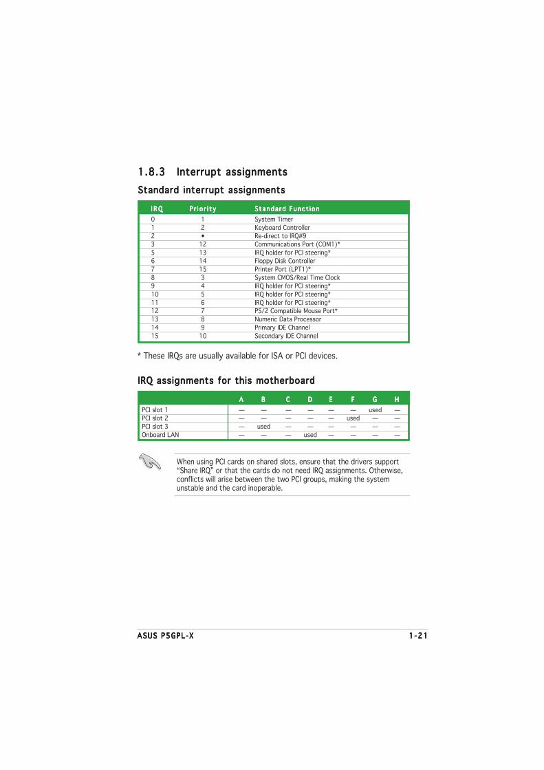
1.8.31.8.31.8.31.8.31.8.3 Interrupt assignmentsInterrupt assignmentsInterrupt assignmentsInterrupt assignmentsInterrupt assignments
Standard interrupt assignmentsStandard interrupt assignmentsStandard interrupt assignmentsStandard interrupt assignmentsStandard interrupt assignments
I R QI R QI R QI R QI R Q P r i o r i t yP r i o r i t yP r i o r i t yP r i o r i t yP r i o r i t y S tanda rd Func t i onStanda rd Func t i onStanda rd Func t i onStanda rd Func t i onStanda rd Func t i on
0 1 System Timer
1 2 Keyboard Controller
2 • Re-direct to IRQ#9
3 12 Communications Port (COM1)*
5 13 IRQ holder for PCI steering*6 14 Floppy Disk Controller
7 15 Printer Port (LPT1)*
8 3 System CMOS/Real Time Clock
9 4 IRQ holder for PCI steering*
10 5 IRQ holder for PCI steering*
11 6 IRQ holder for PCI steering*12 7 PS/2 Compatible Mouse Port*
13 8 Numeric Data Processor
14 9 Primary IDE Channel
15 10 Secondary IDE Channel
* These IRQs are usually available for ISA or PCI devices.
IRQ assignments for this motherboardIRQ assignments for this motherboardIRQ assignments for this motherboardIRQ assignments for this motherboardIRQ assignments for this motherboard
AAAAA BBBBB CCCCC DDDDD EEEEE FFFFF GGGGG HHHHH
PCI slot 1 — — — — — — used —PCI slot 2 — — — — — used — —
PCI slot 3 — used — — — — — —
Onboard LAN — — — used — — — —
When using PCI cards on shared slots, ensure that the drivers support“Share IRQ” or that the cards do not need IRQ assignments. Otherwise,conflicts will arise between the two PCI groups, making the systemunstable and the card inoperable.
1 -221 -221 -221 -221 -22 Chapter 1 : Product int roduct ionChapter 1 : Product int roduct ionChapter 1 : Product int roduct ionChapter 1 : Product int roduct ionChapter 1 : Product int roduct ion
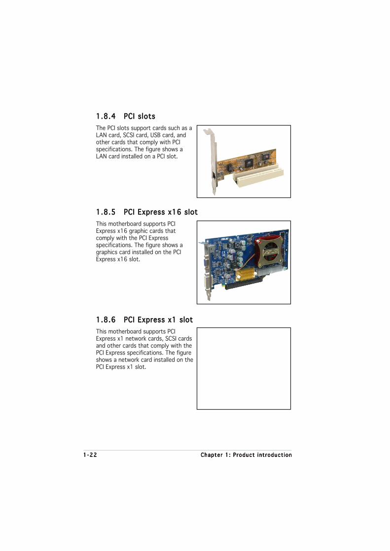
1.8.41.8.41.8.41.8.41.8.4 PCI slotsPCI slotsPCI slotsPCI slotsPCI slots
The PCI slots support cards such as aLAN card, SCSI card, USB card, andother cards that comply with PCIspecifications. The figure shows aLAN card installed on a PCI slot.
1.8.51.8.51.8.51.8.51.8.5 PCI Express x16 slotPCI Express x16 slotPCI Express x16 slotPCI Express x16 slotPCI Express x16 slot
This motherboard supports PCIExpress x16 graphic cards thatcomply with the PCI Expressspecifications. The figure shows agraphics card installed on the PCIExpress x16 slot.
1.8.61.8.61.8.61.8.61.8.6 PCI Express x1 slotPCI Express x1 slotPCI Express x1 slotPCI Express x1 slotPCI Express x1 slot
This motherboard supports PCIExpress x1 network cards, SCSI cardsand other cards that comply with thePCI Express specifications. The figureshows a network card installed on thePCI Express x1 slot.

ASUS P5GPL-XASUS P5GPL-XASUS P5GPL-XASUS P5GPL-XASUS P5GPL-X 1 -231 -231 -231 -231 -23
1.9 Jumpers
1 .1 .1 .1 .1 . C lear RTC RAM (CLRTC)Clear RTC RAM (CLRTC)Clear RTC RAM (CLRTC)Clear RTC RAM (CLRTC)Clear RTC RAM (CLRTC)
This jumper allows you to clear the Real Time Clock (RTC) RAM inCMOS. You can clear the CMOS memory of date, time, and systemsetup parameters by erasing the CMOS RTC RAM data. The onboardbutton cell battery powers the RAM data in CMOS, which includesystem setup information such as system passwords.
To erase the RTC RAM:
1. Turn OFF the computer and unplug the power cord.
2. Remove the onboard battery.
3. Move the jumper cap from pins 1-2 (default) to pins 2-3. Keep thecap on pins 2-3 for about 5~10 seconds, then move the cap back topins 1-2.
4. Re-install the battery.
5. Plug the power cord and turn ON the computer.
6. Hold down the <Del> key during the boot process and enter BIOSsetup to re-enter data.
Except when clearing the RTC RAM, never remove the cap on CLRTCjumper default position. Removing the cap will cause system boot failure!
You do not need to clear the RTC when the system hangs due tooverclocking. For system failure due to overclocking, use the C.P.R. (CPUParameter Recall) feature. Shut down and reboot the system so the BIOScan automatically reset parameter settings to default values.
P5GPL-X
®
P5GPL-X Clear RTC RAM setting
CLRTC
Normal Clear CMOS(Default)
1 2 2 3

1 -241 -241 -241 -241 -24 Chapter 1 : Product int roduct ionChapter 1 : Product int roduct ionChapter 1 : Product int roduct ionChapter 1 : Product int roduct ionChapter 1 : Product int roduct ion
2 .2 .2 .2 .2 . USB device wake-up (3-pin USBPW12, USBPW34,USB device wake-up (3-pin USBPW12, USBPW34,USB device wake-up (3-pin USBPW12, USBPW34,USB device wake-up (3-pin USBPW12, USBPW34,USB device wake-up (3-pin USBPW12, USBPW34,USBPW56, USBPW78)USBPW56, USBPW78)USBPW56, USBPW78)USBPW56, USBPW78)USBPW56, USBPW78)
Set these jumpers to +5V to wake up the computer from S1 sleepmode (CPU stopped, DRAM refreshed, system running in low powermode) using the connected USB devices. Set to +5VSB to wake upfrom S3 and S4 sleep modes (no power to CPU, DRAM in slow refresh,power supply in reduced power mode).
The USBPW1 jumpers are for the rear USB ports. The USBPW2 jumperis for the internal USB connectors that you can connect to additionalUSB ports.
• The USB device wake-up feature requires a power supply that canprovide 500mA on the +5VSB lead for each USB port; otherwise,the system would not power up.
• The total current consumed must NOT exceed the power supplycapability (+5VSB) whether under normal condition or in sleep mode.
P5GPL-X
®
USBPW2
+5V(Default)
+5VSB
3221
+5V(Default)
+5VSB
USBPW1
322
1
P5GPL-X USB device wake-up
ASUS P5GPL-XASUS P5GPL-XASUS P5GPL-XASUS P5GPL-XASUS P5GPL-X 1 -251 -251 -251 -251 -25
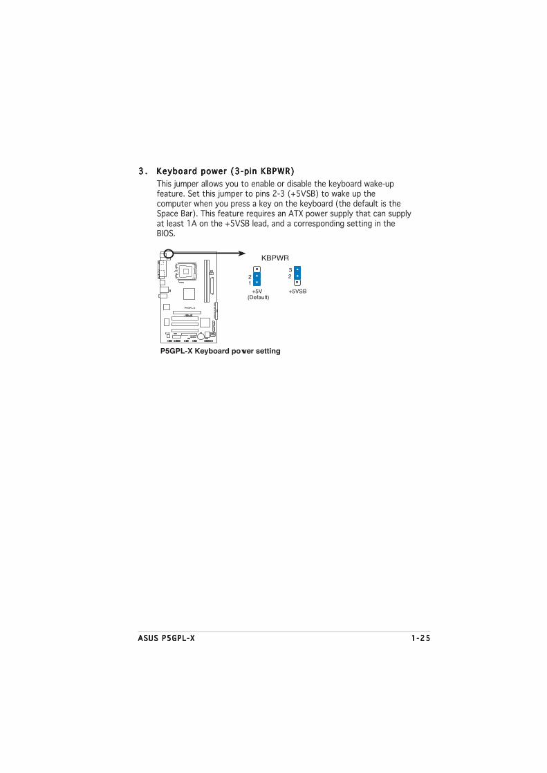
3 .3 .3 .3 .3 . Keyboard power (3-p in KBPWR)Keyboard power (3-p in KBPWR)Keyboard power (3-p in KBPWR)Keyboard power (3-p in KBPWR)Keyboard power (3-p in KBPWR)
This jumper allows you to enable or disable the keyboard wake-upfeature. Set this jumper to pins 2-3 (+5VSB) to wake up thecomputer when you press a key on the keyboard (the default is theSpace Bar). This feature requires an ATX power supply that can supplyat least 1A on the +5VSB lead, and a corresponding setting in theBIOS.
P5GPL-X
®
+5V(Default)
+5VSB
KBPWR
322
1
P5GPL-X Keyboard power setting

1 -261 -261 -261 -261 -26 Chapter 1 : Product int roduct ionChapter 1 : Product int roduct ionChapter 1 : Product int roduct ionChapter 1 : Product int roduct ionChapter 1 : Product int roduct ion
Audio 2, 4, or 6-channel configurationAudio 2, 4, or 6-channel configurationAudio 2, 4, or 6-channel configurationAudio 2, 4, or 6-channel configurationAudio 2, 4, or 6-channel configuration
Light Blue Line In Surround Speaker Out Surround Speaker Out
Lime Line Out Front Speaker Out Front Speaker Out
Pink Mic In Mic In Bass/Center
P o r tP o r tP o r tP o r tP o r t H e a d s e tH e a d s e tH e a d s e tH e a d s e tH e a d s e t 4 - channe l4 - channe l4 - channe l4 - channe l4 - channe l 6 - channe l6 - channe l6 - channe l6 - channe l6 - channe l2-channel2-channel2-channel2-channel2-channel
Refer to the audio configuration table for the function of the audio portsin 2, 4, or 6-channel configuration.
1.10 Connectors
1.10.11.10.11.10.11.10.11.10.1 Rear panel connectorsRear panel connectorsRear panel connectorsRear panel connectorsRear panel connectors
1 .1 .1 .1 .1 . PS/2 mouse port (green).PS/2 mouse port (green).PS/2 mouse port (green).PS/2 mouse port (green).PS/2 mouse port (green). This port is for a PS/2 mouse.
2 .2 .2 .2 .2 . Para l le l port .Para l le l port .Para l le l port .Para l le l port .Para l le l port . This 25-pin port connects a parallel printer, a scanner,or other devices.
3 .3 .3 .3 .3 . LAN (RJ-45) port .LAN (RJ-45) port .LAN (RJ-45) port .LAN (RJ-45) port .LAN (RJ-45) port . This port allows Gigabit connection to a LocalArea Network (LAN) through a network hub. Refer to the table belowfor the LAN port LED indications.
4 .4 .4 .4 .4 . L ine In port ( l ight b lue).L ine In port ( l ight b lue).L ine In port ( l ight b lue).L ine In port ( l ight b lue).L ine In port ( l ight b lue). This port connects a tape, CD, DVDplayer, or other audio sources.
5 .5 .5 .5 .5 . L ine Out port ( l ime).L ine Out port ( l ime).L ine Out port ( l ime).L ine Out port ( l ime).L ine Out port ( l ime). This port connects a headphone or aspeaker. In 4-channel and 6-channel configuration, the function of thisport becomes Front Speaker Out.
6 .6 .6 .6 .6 . Microphone port (p ink). Microphone port (p ink). Microphone port (p ink). Microphone port (p ink). Microphone port (p ink). This port connects a microphone.
1
11 7
2 3
910
4
5
6
8
SPEEDLED
ACT/LINKLED
LAN port
LAN port LED indicationsLAN port LED indicationsLAN port LED indicationsLAN port LED indicationsLAN port LED indications
ACT/L INK LED ACT/L INK LED ACT/L INK LED ACT/L INK LED ACT/L INK LED SPEED LED SPEED LED SPEED LED SPEED LED SPEED LED
S t a t u sS t a t u sS t a t u sS t a t u sS t a t u s Desc r i p t i onDesc r i p t i onDesc r i p t i onDesc r i p t i onDesc r i p t i on S t a t u sS t a t u sS t a t u sS t a t u sS t a t u s Desc r i p t i onDesc r i p t i onDesc r i p t i onDesc r i p t i onDesc r i p t i on
OFF No link OFF 10 Mbps connection
GREEN Linked ORANGE 100 Mbps connection
BLINKING Data activity GREEN 1 Gbps connection
ASUS P5GPL-XASUS P5GPL-XASUS P5GPL-XASUS P5GPL-XASUS P5GPL-X 1 -271 -271 -271 -271 -27
7 .7 .7 .7 .7 . USB 2.0 ports 3 and 4.USB 2.0 ports 3 and 4.USB 2.0 ports 3 and 4.USB 2.0 ports 3 and 4.USB 2.0 ports 3 and 4. These two 4-pin Universal Serial Bus(USB) ports are available for connecting USB 2.0 devices.
8 .8 .8 .8 .8 . USB 2.0 ports 1 and 2.USB 2.0 ports 1 and 2.USB 2.0 ports 1 and 2.USB 2.0 ports 1 and 2.USB 2.0 ports 1 and 2. These two 4-pin Universal Serial Bus(USB) ports are available for connecting USB 2.0 devices.
9 .9 .9 .9 .9 . Coaxia l S/PDIF Out port .Coaxia l S/PDIF Out port .Coaxia l S/PDIF Out port .Coaxia l S/PDIF Out port .Coaxia l S/PDIF Out port . This port connects an external audiooutput device via a coaxial S/PDIF cable.
1 0 .1 0 .1 0 .1 0 .1 0 . Ser ia l connector . Ser ia l connector . Ser ia l connector . Ser ia l connector . Ser ia l connector . This 9-pin COM1 port is for serial devices.
1 1 .1 1 .1 1 .1 1 .1 1 . PS/2 keyboard port (purple) .PS/2 keyboard port (purple) .PS/2 keyboard port (purple) .PS/2 keyboard port (purple) .PS/2 keyboard port (purple) . This port is for a PS/2 keyboard.
1.10.21.10.21.10.21.10.21.10.2 Internal connectorsInternal connectorsInternal connectorsInternal connectorsInternal connectors
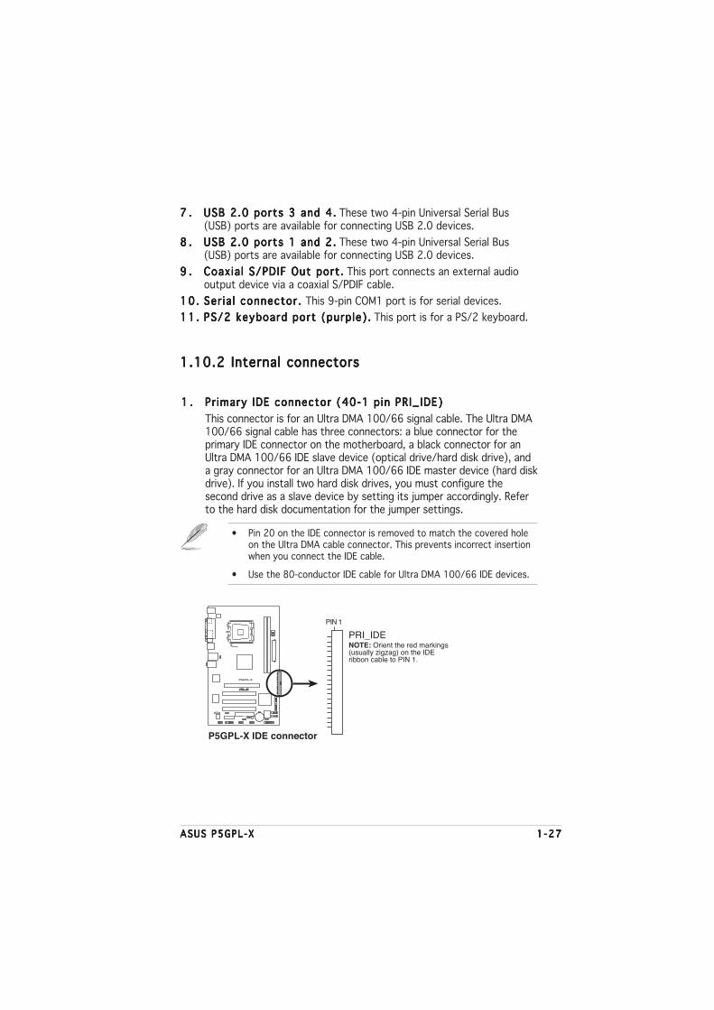
1 .1 .1 .1 .1 . Pr imary IDE connector (40-1 pin PRI_IDE)Pr imary IDE connector (40-1 pin PRI_IDE)Pr imary IDE connector (40-1 pin PRI_IDE)Pr imary IDE connector (40-1 pin PRI_IDE)Pr imary IDE connector (40-1 pin PRI_IDE)
This connector is for an Ultra DMA 100/66 signal cable. The Ultra DMA100/66 signal cable has three connectors: a blue connector for theprimary IDE connector on the motherboard, a black connector for anUltra DMA 100/66 IDE slave device (optical drive/hard disk drive), anda gray connector for an Ultra DMA 100/66 IDE master device (hard diskdrive). If you install two hard disk drives, you must configure thesecond drive as a slave device by setting its jumper accordingly. Referto the hard disk documentation for the jumper settings.
• Pin 20 on the IDE connector is removed to match the covered holeon the Ultra DMA cable connector. This prevents incorrect insertionwhen you connect the IDE cable.
• Use the 80-conductor IDE cable for Ultra DMA 100/66 IDE devices.
P5GPL-X
®
P5GPL-X IDE connector
NOTE: Orient the red markings(usually zigzag) on the IDEribbon cable to PIN 1.
PRI_IDE
PIN 1

1 -281 -281 -281 -281 -28 Chapter 1 : Product int roduct ionChapter 1 : Product int roduct ionChapter 1 : Product int roduct ionChapter 1 : Product int roduct ionChapter 1 : Product int roduct ion
2 .2 .2 .2 .2 . F loppy disk dr ive connector (34-1 pin FLOPPY)Floppy disk dr ive connector (34-1 pin FLOPPY)Floppy disk dr ive connector (34-1 pin FLOPPY)Floppy disk dr ive connector (34-1 pin FLOPPY)Floppy disk dr ive connector (34-1 pin FLOPPY)
This connector is for the provided floppy disk drive (FDD) signal cable.Insert one end of the cable to this connector, then connect the otherend to the signal connector at the back of the floppy disk drive.
Pin 5 on the connector is removed to prevent incorrect cable connectionwhen using an FDD cable with a covered Pin 5.
P5GPL-X
®
NOTE: Orient the red markings onthe floppy ribbon cable to PIN 1.
P5GPL-X Floppy disk drive connector
FLOPPY
PIN 1
3 .3 .3 .3 .3 . CPU and chass is fan connectorsCPU and chass is fan connectorsCPU and chass is fan connectorsCPU and chass is fan connectorsCPU and chass is fan connectors(4-pin CPU_FAN, 3-pin CHA_FAN)(4-pin CPU_FAN, 3-pin CHA_FAN)(4-pin CPU_FAN, 3-pin CHA_FAN)(4-pin CPU_FAN, 3-pin CHA_FAN)(4-pin CPU_FAN, 3-pin CHA_FAN)
The fan connectors support cooling fans of 350mA~2000mA (24Wmax.) or a total of 1A~3.48A (41.36W max.) at +12V. Connect the fancables to the fan connectors on the motherboard, making sure that theblack wire of each cable matches the ground pin of the connector.
Do not forget to connect the fan cables to the fan connectors.Insufficient air flow inside the system may damage the motherboardcomponents. These are not jumpers! DO NOT place jumper caps on thefan connectors.
P5GPL-X
®
P5GPL-X Fan connectors
CPU_FAN
CHA_FAN
GN
DC
PU
FA
N P
WR
CP
U F
AN
INC
PU
FA
N P
WM
GN
D
Rot
atio
n+
12V

ASUS P5GPL-XASUS P5GPL-XASUS P5GPL-XASUS P5GPL-XASUS P5GPL-X 1 -291 -291 -291 -291 -29
4 .4 .4 .4 .4 . Ser ia l ATA connectorsSer ia l ATA connectorsSer ia l ATA connectorsSer ia l ATA connectorsSer ia l ATA connectors(7-pin SATA1, SATA2, SATA3, SATA4)(7-pin SATA1, SATA2, SATA3, SATA4)(7-pin SATA1, SATA2, SATA3, SATA4)(7-pin SATA1, SATA2, SATA3, SATA4)(7-pin SATA1, SATA2, SATA3, SATA4)
These connectors are for the Serial ATA signal cables for Serial ATAhard disk drives.
Important notes on Ser ia l ATAImportant notes on Ser ia l ATAImportant notes on Ser ia l ATAImportant notes on Ser ia l ATAImportant notes on Ser ia l ATA
• Install the Windows® 2000 Service Pack 4 or the Windows® XPService Pack1 before using Serial ATA.
• Plug your Serial ATA boot disk on the master port (SATA1 andSATA2) to support S3 function. Refer to the table below for details.
Serial ATA Master/Slave connectorsSerial ATA Master/Slave connectorsSerial ATA Master/Slave connectorsSerial ATA Master/Slave connectorsSerial ATA Master/Slave connectors
Connec to rConnec to rConnec to rConnec to rConnec to r Se t t i n gSe t t i n gSe t t i n gSe t t i n gSe t t i n g U s eU s eU s eU s eU s e
SATA1, SATA2 Master Boot disk
SATA3, SATA4 Slave Data disk
P5GPL-X
®
P5GPL-X SATA connectors
SATA1
SATA2
SATA3
SATA4
GNDRSATA_TXP4RSATA_TXN4GNDRSATA_RXP4RSATA_RXN4GND
GNDRSATA_TXP3RSATA_TXN3GNDRSATA_RXP3RSATA_RXN3GND
GN
DR
SAT
A_T
XP
2R
SAT
A_T
XN
2G
ND
RS
ATA
_RX
P2
RS
ATA
_RX
N2
GN
D
GN
DR
SAT
A_T
XP
1R
SAT
A_T
XN
1G
ND
RS
ATA
_RX
P1
RS
ATA
_RX
N1
GN
D

1 -301 -301 -301 -301 -30 Chapter 1 : Product int roduct ionChapter 1 : Product int roduct ionChapter 1 : Product int roduct ionChapter 1 : Product int roduct ionChapter 1 : Product int roduct ion
5 .5 .5 .5 .5 . Chass is intrus ion connector (4-1 pin CHASSIS)Chassis intrus ion connector (4-1 pin CHASSIS)Chassis intrus ion connector (4-1 pin CHASSIS)Chassis intrus ion connector (4-1 pin CHASSIS)Chassis intrus ion connector (4-1 pin CHASSIS)
This connector is for a chassis-mounted intrusion detection sensor orswitch. Connect one end of the chassis intrusion sensor or switchcable to this connector. The chassis intrusion sensor or switch sends ahigh-level signal to this connector when a chassis component isremoved or replaced. The signal is then generated as a chassisintrusion event.
By default, the pins labeled “Chassis Signal” and “Ground” are shortedwith a jumper cap. Remove the jumper caps only when you intend touse the chassis intrusion detection feature.
P5GPL-X
®
P5GPL-X Chassis intrusion connector
CHASSIS
+5V
SB
_MB
Cha
ssis
Sig
nal
GN
D
(Default)
Never connect a 1394 cab le1394 cab le1394 cab le1394 cab le1394 cab le to the USB connectors. Doing so willdamage the motherboard!
6 .6 .6 .6 .6 . USB connectors (10-1 pin USB56, USB78)USB connectors (10-1 pin USB56, USB78)USB connectors (10-1 pin USB56, USB78)USB connectors (10-1 pin USB56, USB78)USB connectors (10-1 pin USB56, USB78)
These connectors are for USB 2.0 ports. Connect the USB/GAMEmodule cable to any of these connectors, then install the module to aslot opening at the back of the system chassis.
P5GPL-X
®
P5GPL-X USB 2.0 connectors
USB56
US
B+
5VU
SB
_P6-
US
B_P
6+G
ND
NC
US
B+
5VU
SB
_P5-
US
B_P
5+G
ND
1USB78
US
B+
5VU
SB
_P8-
US
B_P
8+G
ND
NC
US
B+
5VU
SB
_P7-
US
B_P
7+G
ND
1
Game/MIDI module is purchased separately.

ASUS P5GPL-XASUS P5GPL-XASUS P5GPL-XASUS P5GPL-XASUS P5GPL-X 1 -311 -311 -311 -311 -31
7 .7 .7 .7 .7 . Opt ica l dr ive audio connector (4-pin CD)Optica l dr ive audio connector (4-pin CD)Optica l dr ive audio connector (4-pin CD)Optica l dr ive audio connector (4-pin CD)Optica l dr ive audio connector (4-pin CD)
This connector is for the 4-pin audio cable that connects to the audioconnector at the back of the optical drive.
P5GPL-X
®
P5GPL-X CD audio connector
CD
Rig
ht A
udio
Cha
nnel
Left
Aud
io C
hann
elG
roun
dG
roun
d

1 -321 -321 -321 -321 -32 Chapter 1 : Product int roduct ionChapter 1 : Product int roduct ionChapter 1 : Product int roduct ionChapter 1 : Product int roduct ionChapter 1 : Product int roduct ion
8 .8 .8 .8 .8 . ATX power connectors (24-pin EATXPWR, 4-pin ATX12V)ATX power connectors (24-pin EATXPWR, 4-pin ATX12V)ATX power connectors (24-pin EATXPWR, 4-pin ATX12V)ATX power connectors (24-pin EATXPWR, 4-pin ATX12V)ATX power connectors (24-pin EATXPWR, 4-pin ATX12V)
These connectors are for an ATX power supply. The plugs from thepower supply are designed to fit these connectors in only oneorientation. Find the proper orientation and push down firmly until theconnectors completely fit.
• It is recommended that you use an ATX 12 V Specification2.0-compliant power supply unit (PSU) with a minimum of 350 Wpower rating. This PSU type has 24-pin and 4-pin power plugs.
• If you intent to use a PSU with 20-pin and 4-pin power plugs, makesure that the 20-pin power plug can provide at least 15A on +12Vand that the PSU has a minimum power rating of 350 W. The systemmay become unstable or may not boot up if the power isinadequate.
• Do not forget to connect the 4-pin ATX +12 V power plug;otherwise, the system will not boot up.
• Use of a PSU with a higher power output is recommended whenconfiguring a system with more power-consuming devices. Thesystem may become unstable or may not boot up if the power isinadequate.
• The ATX 12 V Specification 2.0-compliant PSU passed themotherboard power requirement test with the followingconfiguration:
CPU : Intel® Pentium® 4 3.6 GHzMemory : 512 MB DDR (x 4)Graphics card : PCI Express x16 Nvidia EN5900Parallel ATA devices: IDE hard disk drive (x 2)Serial ATA device : SATA hard disk driveOptical drive : CD-ROM
• You must install a PSU with a higher power rating if you intend toinstall additional devices.
P5GPL-X
®
P5GPL-X ATX power connectors
EATXPWR
ATX12V
+3 Volts+3 VoltsGround+5 Volts
+5 VoltsGround
GroundPower OK
+5V Standby+12 Volts
-5 Volts
+5 Volts
+3 Volts-12 VoltsGround
GroundGroundPSON#
Ground
+5 Volts
+12 Volts+3 Volts
+5 VoltsGround
+12V DC
GND
GND
+12V DC

ASUS P5GPL-XASUS P5GPL-XASUS P5GPL-XASUS P5GPL-XASUS P5GPL-X 1 -331 -331 -331 -331 -33
1 0 .1 0 .1 0 .1 0 .1 0 . Dig ita l Audio connector (4-1 pin SPDIF_OUT)Dig ita l Audio connector (4-1 pin SPDIF_OUT)Dig ita l Audio connector (4-1 pin SPDIF_OUT)Dig ita l Audio connector (4-1 pin SPDIF_OUT)Dig ita l Audio connector (4-1 pin SPDIF_OUT)
This connector is for the S/PDIF audio module to allow digital soundoutput. Connect one end of the S/PDIF audio cable to this connectorand the other end to the S/PDIF module.
P5GPL-X
®
P5GPL-X Digital audio connector
+5V
SP
DIF
OU
TG
ND
SPDIF_OUT
P5GPL-X
®
P5GPL-X Analog front panel connector
AAFPLegacy AC’97
compliant definitionAzalia
compliant definition
SE
NS
E2_
RE
TU
R
PO
RT
1 L
PO
RT
2 R
PO
RT
2 L
SE
NS
E1_
RE
TU
RS
EN
SE
_SE
ND
PO
RT
1 R
PR
ES
EN
CE
#G
ND
BLI
NE
_OU
T_L
MIC
2
Line
out
_R
Line
out
_L
BLI
NE
_OU
T_R
NC
MIC
PW
R+
5VA
AG
ND
9 .9 .9 .9 .9 . Front panel audio connector (10-1 pin AAFP)Front panel audio connector (10-1 pin AAFP)Front panel audio connector (10-1 pin AAFP)Front panel audio connector (10-1 pin AAFP)Front panel audio connector (10-1 pin AAFP)
This connector is for a chassis-mounted front panel audio I/O modulethat supports either HD Audio or legacy AC ‘97 audio standard.Connect one end of the front panel audio I/O module cable to thisconnector.
• Connect a high-definiton front panel audio module to this connectorto avail the high-definition audio features of the motherboard.
The S/PDIF module is purchased separately.

1 -341 -341 -341 -341 -34 Chapter 1 : Product int roduct ionChapter 1 : Product int roduct ionChapter 1 : Product int roduct ionChapter 1 : Product int roduct ionChapter 1 : Product int roduct ion
1 1 .1 1 .1 1 .1 1 .1 1 . System panel connector (20-pin PANEL)System panel connector (20-pin PANEL)System panel connector (20-pin PANEL)System panel connector (20-pin PANEL)System panel connector (20-pin PANEL)
This connector supports several chassis-mounted functions.
The sytem panel connector is color-coded for easy connection. Refer tothe connector description below for details.
• System power LED (Green 3-pin PLED)System power LED (Green 3-pin PLED)System power LED (Green 3-pin PLED)System power LED (Green 3-pin PLED)System power LED (Green 3-pin PLED)This 3-pin connector is for the system power LED. Connect thechassis power LED cable to this connector. The system power LEDlights up when you turn on the system power, and blinks when thesystem is in sleep mode.
• Hard d isk dr ive act iv ity (Red 2-pin IDE_LED)Hard d isk dr ive act iv ity (Red 2-pin IDE_LED)Hard d isk dr ive act iv ity (Red 2-pin IDE_LED)Hard d isk dr ive act iv ity (Red 2-pin IDE_LED)Hard d isk dr ive act iv ity (Red 2-pin IDE_LED)This 2-pin connector is for the HDD Activity LED. Connect the HDDActivity LED cable to this connector. The IDE LED lights up or flasheswhen data is read from or written to the HDD.
• System warning speaker (Orange 4-pin SPEAKER)System warning speaker (Orange 4-pin SPEAKER)System warning speaker (Orange 4-pin SPEAKER)System warning speaker (Orange 4-pin SPEAKER)System warning speaker (Orange 4-pin SPEAKER)This 4-pin connector is for the chassis-mounted system warningspeaker. The speaker allows you to hear system beeps and warnings.
• Power/Soft-off button (Yel low 2-pin PWRSW)Power/Soft-off button (Yel low 2-pin PWRSW)Power/Soft-off button (Yel low 2-pin PWRSW)Power/Soft-off button (Yel low 2-pin PWRSW)Power/Soft-off button (Yel low 2-pin PWRSW)This connector is for the system power button. Pressing the powerbutton turns the system ON or puts the system in SLEEP or SOFT-OFFmode depending on the BIOS settings. Pressing the power switch formore than four seconds while the system is ON turns the system OFF.
• Reset button (Blue 2-pin RESET)Reset button (Blue 2-pin RESET)Reset button (Blue 2-pin RESET)Reset button (Blue 2-pin RESET)Reset button (Blue 2-pin RESET)This 2-pin connector is for the chassis-mounted reset button forsystem reboot without turning off the system power.
P5GPL-X
®
P5GPL-X System panel connector
PANEL
PLE
D-
PW
R+
5V Spe
aker
SPEAKERPLED
Gro
und
Reset
Gro
und
Res
etG
roun
dG
roun
d
PWRSWP
LED
+ID
E_L
ED
-ID
E_L
ED
+IDE_LED

ASUS P5GPL-XASUS P5GPL-XASUS P5GPL-XASUS P5GPL-XASUS P5GPL-X 2 - 12 - 12 - 12 - 12 - 1
2This chapter tells how to changethe system settings through the BIOSSetup menus. Detailed descriptionsof the BIOS parameters are alsoprovided.
BIOS setup

2 - 22 - 22 - 22 - 22 - 2 Chapter 2 : B IOS setupChapter 2 : B IOS setupChapter 2 : B IOS setupChapter 2 : B IOS setupChapter 2 : B IOS setup
2.1 Managing and updating your BIOS
The following utilities allow you to manage and update the motherboardBasic Input/Output System (BIOS) setup.
1. ASUS AFUDOS ASUS AFUDOS ASUS AFUDOS ASUS AFUDOS ASUS AFUDOS (Updates the BIOS in DOS mode using a bootablefloppy disk.)
2. ASUS EZ F lash ASUS EZ F lash ASUS EZ F lash ASUS EZ F lash ASUS EZ F lash (Updates the BIOS using a floppy disk during POST.)
3. ASUS CrashFree BIOS 2 ASUS CrashFree BIOS 2 ASUS CrashFree BIOS 2 ASUS CrashFree BIOS 2 ASUS CrashFree BIOS 2 (Updates the BIOS using a bootablefloppy disk or the motherboard support CD when the BIOS file fails orgets corrupted.)
4. ASUS Update ASUS Update ASUS Update ASUS Update ASUS Update (Updates the BIOS in Windows® environment.)
Refer to the corresponding sections for details on these utilities.
2.1.12.1.12.1.12.1.12.1.1 Creating a bootable floppy diskCreating a bootable floppy diskCreating a bootable floppy diskCreating a bootable floppy diskCreating a bootable floppy disk
1. Do either one of the following to create a bootable floppy disk.
DOS environment
a. Insert a 1.44MB floppy disk into the drive.
b. At the DOS prompt, type format A:/S then press <Enter>.
Windows® XP environment
a. Insert a 1.44 MB floppy disk to the floppy disk drive.
b. Click Star t Star t Star t Star t Star t from the Windows® desktop, then select M yM yM yM yM yComputerComputerComputerComputerComputer.
c. Select the 3 1/2 Floppy Drive icon.
d. Click F i l e F i l e F i l e F i l e F i l e from the menu, then select FormatFormatFormatFormatFormat. A Format 3 1/2Format 3 1/2Format 3 1/2Format 3 1/2Format 3 1/2F loppy D iskF loppy D iskF loppy D iskF loppy D iskF loppy D isk window appears.
e. Select Create an MS-DOS startup d isk Create an MS-DOS startup d isk Create an MS-DOS startup d isk Create an MS-DOS startup d isk Create an MS-DOS startup d isk from the formatoptions field, then click Sta r tSta r tSta r tSta r tSta r t.
Windows® 2000 environment
To create a set of boot disks for Windows® 2000:
a. Insert a formatted, high density 1.44 MB floppy disk into the drive.
b. Insert the Windows® 2000 CD to the optical drive.
c. Click Sta r tSta r tSta r tSta r tSta r t, then select R unRunRunRunRun.
Save a copy of the original motherboard BIOS file to a bootable floppydisk in case you need to restore the BIOS in the future. Copy the originalmotherboard BIOS using the ASUS Update or AFUDOS utilities.

ASUS P5GPL-XASUS P5GPL-XASUS P5GPL-XASUS P5GPL-XASUS P5GPL-X 2 - 32 - 32 - 32 - 32 - 3
d. From the Open field, type
D:\bootdisk\makeboot a:
assuming that D: is your optical drive.
e. Press <Enter>, then follow screen instructions to continue.
2. Copy the original or the latest motherboard BIOS file to the bootablefloppy disk.
2.1.22.1.22.1.22.1.22.1.2 ASUS EZ Flash utilityASUS EZ Flash utilityASUS EZ Flash utilityASUS EZ Flash utilityASUS EZ Flash utility
The ASUS EZ Flash feature allows you to update the BIOS without having togo through the long process of booting from a floppy disk and using aDOS-based utility. The EZ Flash utility is built-in the BIOS chip so it isaccessible by pressing <Alt> + <F2> during the Power-On Self Tests(POST).
To update the BIOS using EZ Flash:
1. Visit the ASUS website (www.asus.com) to download the latest BIOSfile for the motherboard and rename the same to P5GPLX.ROMP5GPLX.ROMP5GPLX.ROMP5GPLX.ROMP5GPLX.ROM.
2. Save the BIOS file to a floppy disk, then restart the system.
3. Press <Alt> + <F2> during POST to display the following.
EZFlash starting BIOS update
Checking for floppy...
4. Insert the floppy disk that contains the BIOS file to the floppy diskdrive. When the correct BIOS file is found, EZ Flash performs the BIOSupdate process and automatically reboots the system when done.
EZFlash starting BIOS update
Checking for floppy...
Floppy found!
Reading file “P5GPLX.ROM”. Completed.
Start erasing.......|
Start programming...|
Flashed successfully. Rebooting.
• Do not shutdown or reset the system while updating the BIOS toprevent system boot failure!
• A “Floppy not found!” error message appears if there is no floppydisk in the drive. A “P5GPLX.ROM not found!” error message appearsif the correct BIOS file is not found in the floppy disk. Make sure thatyou rename the BIOS file to P5GPLX.ROM.
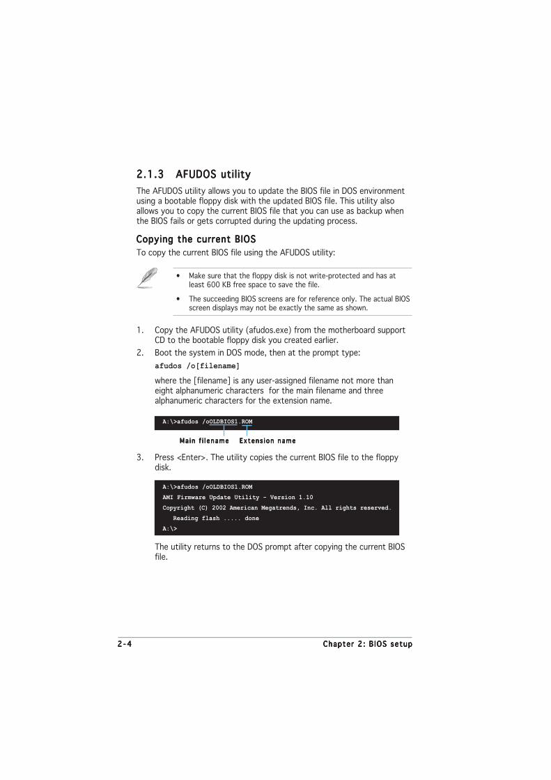
2 - 42 - 42 - 42 - 42 - 4 Chapter 2 : B IOS setupChapter 2 : B IOS setupChapter 2 : B IOS setupChapter 2 : B IOS setupChapter 2 : B IOS setup
2.1.32.1.32.1.32.1.32.1.3 AFUDOS utilityAFUDOS utilityAFUDOS utilityAFUDOS utilityAFUDOS utility
The AFUDOS utility allows you to update the BIOS file in DOS environmentusing a bootable floppy disk with the updated BIOS file. This utility alsoallows you to copy the current BIOS file that you can use as backup whenthe BIOS fails or gets corrupted during the updating process.
Copying the current BIOSCopying the current BIOSCopying the current BIOSCopying the current BIOSCopying the current BIOS
To copy the current BIOS file using the AFUDOS utility:
The utility returns to the DOS prompt after copying the current BIOSfile.
3. Press <Enter>. The utility copies the current BIOS file to the floppydisk.
A:\>afudos /oOLDBIOS1.ROM
AMI Firmware Update Utility - Version 1.10
Copyright (C) 2002 American Megatrends, Inc. All rights reserved.
Reading flash ..... done
A:\>
Ma in f i l e nameMa i n f i l e nameMa i n f i l e nameMa i n f i l e nameMa i n f i l e name Ex tens i on nameEx tens i on nameEx tens i on nameEx tens i on nameEx tens i on name
1. Copy the AFUDOS utility (afudos.exe) from the motherboard supportCD to the bootable floppy disk you created earlier.
2. Boot the system in DOS mode, then at the prompt type:
afudos /o[filename]
where the [filename] is any user-assigned filename not more thaneight alphanumeric characters for the main filename and threealphanumeric characters for the extension name.
A:\>afudos /oOLDBIOS1.ROM
• Make sure that the floppy disk is not write-protected and has atleast 600 KB free space to save the file.
• The succeeding BIOS screens are for reference only. The actual BIOSscreen displays may not be exactly the same as shown.

ASUS P5GPL-XASUS P5GPL-XASUS P5GPL-XASUS P5GPL-XASUS P5GPL-X 2 - 52 - 52 - 52 - 52 - 5
5. The utility returns to the DOS prompt after the BIOS update process iscompleted. Reboot the system from the hard disk drive.
A:\>afudos /iP5GPLX.ROM
AMI Firmware Update Utility - Version 1.10
Copyright (C) 2002 American Megatrends, Inc. All rights reserved.
Reading file ..... done
Erasing flash .... done
Writing flash .... 0x0008CC00 (9%)
Verifying flash .. done
A:\>
2. Copy the AFUDOS utility (afudos.exe) from the motherboard supportCD to the bootable floppy disk you created earlier.
3. Boot the system in DOS mode, then at the prompt type:
afudos /i[filename]
where [filename] is the latest or the original BIOS file on the bootablefloppy disk.
A:\>afudos /iP5GPLX.ROM
AMI Firmware Update Utility - Version 1.10
Copyright (C) 2002 American Megatrends, Inc. All rights reserved.
Reading file ..... done
Erasing flash .... done
Writing flash .... 0x0008CC00 (9%)
Updating the BIOS fi leUpdating the BIOS fi leUpdating the BIOS fi leUpdating the BIOS fi leUpdating the BIOS fi le
To update the BIOS file using the AFUDOS utility:
1. Visit the ASUS website (www.asus.com) and download the latest BIOSfile for the motherboard. Save the BIOS file to a bootable floppy disk.
A:\>afudos /iP5GPLX.ROM
4. The utility verifies the file and starts updating the BIOS.
Do not shut down or reset the system while updating the BIOS toprevent system boot failure!
Write the BIOS filename on a piece of paper. You need to type the exactBIOS filename at the DOS prompt.

2 - 62 - 62 - 62 - 62 - 6 Chapter 2 : B IOS setupChapter 2 : B IOS setupChapter 2 : B IOS setupChapter 2 : B IOS setupChapter 2 : B IOS setup
2.1.42.1.42.1.42.1.42.1.4 ASUS CrashFree BIOS 2 utilityASUS CrashFree BIOS 2 utilityASUS CrashFree BIOS 2 utilityASUS CrashFree BIOS 2 utilityASUS CrashFree BIOS 2 utility
The ASUS CrashFree BIOS 2 is an auto recovery tool that allows you torestore the BIOS file when it fails or gets corrupted during the updatingprocess. You can update a corrupted BIOS file using the motherboardsupport CD or the floppy disk that contains the updated BIOS file.
Recovering the BIOS from a floppy diskRecovering the BIOS from a floppy diskRecovering the BIOS from a floppy diskRecovering the BIOS from a floppy diskRecovering the BIOS from a floppy disk
To recover the BIOS from a floppy disk:
1. Turn on the system.
2. Insert the floppy disk with the original or updated BIOS file to thefloppy disk drive.
3. The utility displays the following message and automatically checksthe floppy disk for the original or updated BIOS file.
Bad BIOS checksum. Starting BIOS recovery...
Checking for floppy...
4. Restart the system after the utility completes the updating process.
Bad BIOS checksum. Starting BIOS recovery...
Checking for floppy...
Floppy found!
Reading file “P5GPLX.ROM”. Completed.
Start flashing...
When found, the utility reads the BIOS file and starts flashing thecorrupted BIOS file.
DO NOT shut down or reset the system while updating the BIOS! Doingso can cause system boot failure!
• Prepare the motherboard support CD or the floppy disk containingthe updated motherboard BIOS before using this utility.
• Make sure that you rename the original or updated BIOS file in thefloppy disk to P5GPLX .ROMP5GPLX .ROMP5GPLX .ROMP5GPLX .ROMP5GPLX .ROM.

ASUS P5GPL-XASUS P5GPL-XASUS P5GPL-XASUS P5GPL-XASUS P5GPL-X 2 - 72 - 72 - 72 - 72 - 7
The recovered BIOS may not be the latest BIOS version for thismotherboard. Visit the ASUS website (www.asus.com) to download thelatest BIOS file.
Recovering the BIOS from the support CDRecovering the BIOS from the support CDRecovering the BIOS from the support CDRecovering the BIOS from the support CDRecovering the BIOS from the support CD
To recover the BIOS from the support CD:
1. Remove any floppy disk from the floppy disk drive, then turn on thesystem.
2. Insert the support CD to the optical drive.
3. The utility displays the following message and automatically checksthe floppy disk for the original or updated BIOS file.
4. Restart the system after the utility completes the updating process.
DO NOT shut down or reset the system while updating the BIOS! Doingso can cause system boot failure!
Bad BIOS checksum. Starting BIOS recovery...
Checking for floppy...
Floppy not found!
Checking for CD-ROM...
CD-ROM found!
Reading file “P5GPLX.ROM”. Completed.
Start flashing...
When no floppy disk is found, the utility automatically checks theoptical drive for the original or updated BIOS file. The utility thenupdates the corrupted BIOS file.
Bad BIOS checksum. Starting BIOS recovery...
Checking for floppy...

2 - 82 - 82 - 82 - 82 - 8 Chapter 2 : B IOS setupChapter 2 : B IOS setupChapter 2 : B IOS setupChapter 2 : B IOS setupChapter 2 : B IOS setup
Install ing ASUS UpdateInstall ing ASUS UpdateInstall ing ASUS UpdateInstall ing ASUS UpdateInstall ing ASUS Update
To install ASUS Update:
1. Place the support CD in the optical drive. The Dr ivers Dr ivers Dr ivers Dr ivers Dr ivers menu appears.
2. Click the Ut i l i t ies Ut i l i t ies Ut i l i t ies Ut i l i t ies Ut i l i t ies tab, then click Insta l l ASUS UpdateInsta l l ASUS UpdateInsta l l ASUS UpdateInsta l l ASUS UpdateInsta l l ASUS UpdateVX.XX.XXVX.XX.XXVX.XX.XXVX.XX.XXVX.XX.XX. See page 3-4 for the Ut i l i t ies Ut i l i t ies Ut i l i t ies Ut i l i t ies Ut i l i t ies screen menu.
3. The ASUS Update utility is copied to your system.
2.1.52.1.52.1.52.1.52.1.5 ASUS Update utilityASUS Update utilityASUS Update utilityASUS Update utilityASUS Update utility
The ASUS Update is a utility that allows you to manage, save, and updatethe motherboard BIOS in Windows® environment. The ASUS Update utilityallows you to:
• Save the current BIOS file
• Download the latest BIOS file from the Internet
• Update the BIOS from an updated BIOS file
• Update the BIOS directly from the Internet, and
• View the BIOS version information.
This utility is available in the support CD that comes with the motherboardpackage.
ASUS Update requires an Internet connection either through a networkor an Internet Service Provider (ISP).
Quit all Windows® applications before you update the BIOS using thisutility.

ASUS P5GPL-XASUS P5GPL-XASUS P5GPL-XASUS P5GPL-XASUS P5GPL-X 2 - 92 - 92 - 92 - 92 - 9
3. Select the ASUS FTP sitenearest you to avoid networktraffic, or click Auto Se lectAuto Se lectAuto Se lectAuto Se lectAuto Se lect.Click NextNextNextNextNext.
Updating the BIOS through the InternetUpdating the BIOS through the InternetUpdating the BIOS through the InternetUpdating the BIOS through the InternetUpdating the BIOS through the Internet
To update the BIOS through the Internet:
1. Launch the ASUS Update utility from the Windows® desktop by clickingStart Star t Star t Star t Star t > Programs Programs Programs Programs Programs > ASUS ASUS ASUS ASUS ASUS > ASUSUpdate ASUSUpdate ASUSUpdate ASUSUpdate ASUSUpdate > ASUSUpdateASUSUpdateASUSUpdateASUSUpdateASUSUpdate. TheASUS Update main window appears.
2. Select Update B IOS fromUpdate B IOS fromUpdate B IOS fromUpdate B IOS fromUpdate B IOS fromthe Internet the Internet the Internet the Internet the Internet option from thedrop-down menu, then clickNextNextNextNextNext.

2 -102 -102 -102 -102 -10 Chapter 2 : B IOS setupChapter 2 : B IOS setupChapter 2 : B IOS setupChapter 2 : B IOS setupChapter 2 : B IOS setup
Updating the BIOS through a BIOS fi leUpdating the BIOS through a BIOS fi leUpdating the BIOS through a BIOS fi leUpdating the BIOS through a BIOS fi leUpdating the BIOS through a BIOS fi le
To update the BIOS through a BIOS file:
1. Launch the ASUS Update utility from the Windows® desktop byclicking Star t Star t Star t Star t Star t > Programs Programs Programs Programs Programs > ASUS ASUS ASUS ASUS ASUS > ASUSUpdate ASUSUpdate ASUSUpdate ASUSUpdate ASUSUpdate >ASUSUpdateASUSUpdateASUSUpdateASUSUpdateASUSUpdate. The ASUS Update main window appears.
2. Select Update B IOS from aUpdate B IOS from aUpdate B IOS from aUpdate B IOS from aUpdate B IOS from af i l e f i l e f i l e f i l e f i l e option from the drop-downmenu, then click NextNextNextNextNext.
4. From the FTP site, select theBIOS version that you wish todownload. Click Next.
5. Follow the screen instructions tocomplete the update process.
The ASUS Update utility iscapable of updating itselfthrough the Internet. Alwaysupdate the utility to avail allits features.
3. Locate the BIOS file from theOpen Open Open Open Open window, then click SaveSaveSaveSaveSave.
4. Follow the screen instructions tocomplete the update process.

ASUS P5GPL-XASUS P5GPL-XASUS P5GPL-XASUS P5GPL-XASUS P5GPL-X 2 -112 -112 -112 -112 -11
2.2 BIOS setup program
This motherboard supports a programmable firmware chip that you canupdate using the provided utility described in section “2.1 Managing andupdating your BIOS.”
Use the BIOS Setup program when you are installing a motherboard,reconfiguring your system, or prompted to “Run Setup”. This sectionexplains how to configure your system using this utility.
Even if you are not prompted to use the Setup program, you can changethe configuration of your computer in the future. For example, you canenable the security password feature or change the power managementsettings. This requires you to reconfigure your system using the BIOSSetup program so that the computer can recognize these changes andrecord them in the CMOS RAM of the firmware hub.
The firmware hub on the motherboard stores the Setup utility. When youstart up the computer, the system provides you with the opportunity torun this program. Press <Del> during the Power-On-Self-Test (POST) toenter the Setup utility; otherwise, POST continues with its test routines.
If you wish to enter Setup after POST, restart the system by pressing<Ctrl+Alt+Delete>, or by pressing the reset button on the system chassis.You can also restart by turning the system off and then back on. Do thislast option only if the first two failed.
The Setup program is designed to make it as easy to use as possible. Beinga menu-driven program, it lets you scroll through the various sub-menusand make your selections from the available options using the navigationkeys.
• The default BIOS settings for this motherboard apply for mostconditions to ensure optimum performance. If the system becomesunstable after changing any BIOS settings, load the default settingsto ensure system compatibility and stability. Select the L o a dL o a dL o a dL o a dL o a dDefau l t Sett ingsDefau l t Sett ingsDefau l t Sett ingsDefau l t Sett ingsDefau l t Sett ings item under the Exit Menu. See section “2.7 ExitMenu.”
• The BIOS setup screens shown in this section are for referencepurposes only, and may not exactly match what you see on yourscreen.
• Visit the ASUS website (www.asus.com) to download the latest BIOSfile for this motherboard and .

2 -122 -122 -122 -122 -12 Chapter 2 : B IOS setupChapter 2 : B IOS setupChapter 2 : B IOS setupChapter 2 : B IOS setupChapter 2 : B IOS setup
System Time [11:51:19]System Date [Thu 05/07/2004]Legacy Diskette A [1.44M, 3.5 in]
Primary IDE Master :[ST320413A]Primary IDE Slave :[Not Detected]Third IDE Master :[Not Detected]Third IDE Slave :[Not Detected]Fourth IDE Master :[Not Detected]Fourth IDE Slave :[Not Detected]IDE Configuration
System Information
2.2.22.2.22.2.22.2.22.2.2 Menu barMenu barMenu barMenu barMenu bar
The menu bar on top of the screen has the following main items:
Ma i nMa inMa inMa inMa in For changing the basic system configuration
AdvancedAdvancedAdvancedAdvancedAdvanced For changing the advanced system settings
PowerPowerPowerPowerPower For changing the advanced power management (APM)configuration
BootBootBootBootBoot For changing the system boot configuration
Ex i tEx i tEx i tEx i tEx i t For selecting the exit options and loading defaultsettings
2.2.12.2.12.2.12.2.12.2.1 BIOS menu screenBIOS menu screenBIOS menu screenBIOS menu screenBIOS menu screen
To select an item on the menu bar, press the right or left arrow key on thekeyboard until the desired item is highlighted.
Some of the navigation keys differ from one screen to another.
Nav i ga t i on keysNav i ga t i on keysNav i ga t i on keysNav i ga t i on keysNav i ga t i on keys
Gene ra l he l pGene ra l he l pGene ra l he l pGene ra l he l pGene ra l he l pMenu b a rMenu b a rMenu b a rMenu b a rMenu b a r
Sub -menu i t emsSub -menu i t emsSub -menu i t emsSub -menu i t emsSub -menu i t ems
Con f i gu ra t i on f i e l d sCon f i gu ra t i on f i e l d sCon f i gu ra t i on f i e l d sCon f i gu ra t i on f i e l d sCon f i gu ra t i on f i e l d sMenu i t emsMenu i t emsMenu i t emsMenu i t emsMenu i t ems
2.2.32.2.32.2.32.2.32.2.3 Navigation keysNavigation keysNavigation keysNavigation keysNavigation keys
At the bottom right corner of a menu screen are the navigation keys forthat particular menu. Use the navigation keys to select items in the menuand change the settings.
Use [ENTER], [TAB]or [SHIFT-TAB] toselect a field.
Use [+] or [-] toconfigure system time.

ASUS P5GPL-XASUS P5GPL-XASUS P5GPL-XASUS P5GPL-XASUS P5GPL-X 2 -132 -132 -132 -132 -13
2.2.42.2.42.2.42.2.42.2.4 Menu itemsMenu itemsMenu itemsMenu itemsMenu items
The highlighted item on the menu bardisplays the specific items for that menu.For example, selecting Ma in Ma in Ma in Ma in Ma in shows theMain menu items.
The other items (Advanced, Power, Boot,and Exit) on the menu bar have theirrespective menu items.
2.2.52.2.52.2.52.2.52.2.5 Sub-menu itemsSub-menu itemsSub-menu itemsSub-menu itemsSub-menu items
A solid triangle before each item on any menu screen means that the itemhas a sub-menu. To display the sub-menu, select the item and press<Enter>.
2.2.62.2.62.2.62.2.62.2.6 Configuration fieldsConfiguration fieldsConfiguration fieldsConfiguration fieldsConfiguration fields
These fields show the values for the menu items. If an item is user-configurable, you can change the value of the field opposite the item. Youcannot select an item that is not user-configurable.
A configurable field is enclosed in brackets, and is highlighted whenselected. To change the value of a field, select it then press <Enter> todisplay a list of options. Refer to “2.2.7 Pop-up window.”
2.2.72.2.72.2.72.2.72.2.7 Pop-up windowPop-up windowPop-up windowPop-up windowPop-up window
Select a menu item then press <Enter> to display a pop-up window withthe configuration options for that item.
2.2.82.2.82.2.82.2.82.2.8 Scroll barScroll barScroll barScroll barScroll bar
A scroll bar appears on the right sideof a menu screen when there areitems that do not fit on the screen.Press theUp/Down arrow keys or <Page Up> /<Page Down> keys to display theother items on the screen.
2.2.92.2.92.2.92.2.92.2.9 General helpGeneral helpGeneral helpGeneral helpGeneral help
At the top right corner of the menuscreen is a brief description of theselected item.
System Time [11:10:19]System Date [Thu 03/27/2003]Legacy Diskette A [1.44M, 3.5 in]Language [English]
Primary IDE Master :[ST320413A] Primary IDE Slave :[ASUS CD-S340] Secondary IDE Master :[Not Detected] Secondary IDE Slave :[Not Detected] Third IDE Master :[Not Detected] Fourth IDE Master :[Not Detected] IDE Configuration
System Information
Use [ENTER], [TAB]or [SHIFT-TAB] toselect a field.
Use [+] or [-] toconfigure system time.
Select Screen Select Item+- Change FieldTab Select FieldF1 General HelpF10 Save and ExitESC Exit
Ma in menu i t emsMa i n menu i t emsMa i n menu i t emsMa i n menu i t emsMa i n menu i t ems
Sc ro l l b a rSc ro l l b a rSc ro l l b a rSc ro l l b a rSc ro l l b a r
Select Screen Select Item+- Change OptionF1 General HelpF10 Save and ExitESC Exit
Advanced Chipset settings
WARNING: Setting wrong values in the sections below may cause system to malfunction.
Configure DRAM Timing by SPD [Enabled]Memory Acceleration Mode [Auto]DRAM Idle Timer [Auto]DRAm Refresh Rate [Auto]
Graphic Adapter Priority [AGP/PCI]Graphics Aperture Size [ 64 MB]Spread Spectrum [Enabled]
ICH Delayed Transaction [Enabled]
MPS Revision [1.4]
Pop -up w i ndowPop -up w i ndowPop -up w i ndowPop -up w i ndowPop -up w i ndow
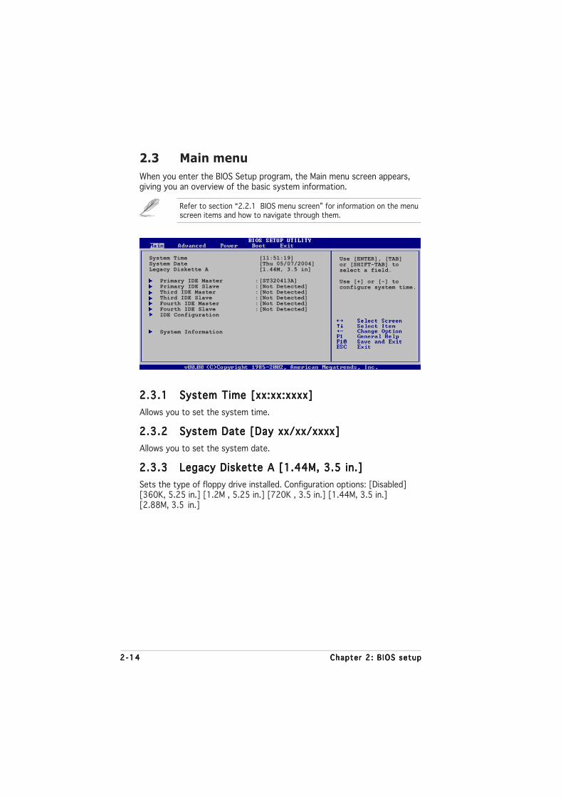
2 -142 -142 -142 -142 -14 Chapter 2 : B IOS setupChapter 2 : B IOS setupChapter 2 : B IOS setupChapter 2 : B IOS setupChapter 2 : B IOS setup
2.3 Main menu
When you enter the BIOS Setup program, the Main menu screen appears,giving you an overview of the basic system information.
2.3.12.3.12.3.12.3.12.3.1 System Time [xx:xx:xxxx]System Time [xx:xx:xxxx]System Time [xx:xx:xxxx]System Time [xx:xx:xxxx]System Time [xx:xx:xxxx]
Allows you to set the system time.
2.3.22.3.22.3.22.3.22.3.2 System Date [Day xx/xx/xxxx]System Date [Day xx/xx/xxxx]System Date [Day xx/xx/xxxx]System Date [Day xx/xx/xxxx]System Date [Day xx/xx/xxxx]
Allows you to set the system date.
2.3.32.3.32.3.32.3.32.3.3 Legacy Diskette A [1.44M, 3.5 in.]Legacy Diskette A [1.44M, 3.5 in.]Legacy Diskette A [1.44M, 3.5 in.]Legacy Diskette A [1.44M, 3.5 in.]Legacy Diskette A [1.44M, 3.5 in.]
Sets the type of floppy drive installed. Configuration options: [Disabled][360K, 5.25 in.] [1.2M , 5.25 in.] [720K , 3.5 in.] [1.44M, 3.5 in.][2.88M, 3.5 in.]
Refer to section “2.2.1 BIOS menu screen” for information on the menuscreen items and how to navigate through them.
System Time [11:51:19]System Date [Thu 05/07/2004]Legacy Diskette A [1.44M, 3.5 in]
Primary IDE Master :[ST320413A]Primary IDE Slave :[Not Detected]Third IDE Master :[Not Detected]Third IDE Slave :[Not Detected]Fourth IDE Master :[Not Detected]Fourth IDE Slave :[Not Detected]IDE Configuration
System Information
Use [ENTER], [TAB]or [SHIFT-TAB] toselect a field.
Use [+] or [-] toconfigure system time.

ASUS P5GPL-XASUS P5GPL-XASUS P5GPL-XASUS P5GPL-XASUS P5GPL-X 2 -152 -152 -152 -152 -15
2.3.42.3.42.3.42.3.42.3.4 Primary, Third and Fourth IDE Master/SlavePrimary, Third and Fourth IDE Master/SlavePrimary, Third and Fourth IDE Master/SlavePrimary, Third and Fourth IDE Master/SlavePrimary, Third and Fourth IDE Master/Slave
While entering Setup, the BIOS automatically detects the presence of IDEdevices. There is a separate sub-menu for each IDE device. Select a deviceitem then press <Enter> to display the IDE device information.
The BIOS automatically detects the values opposite the dimmed items(Device, Vendor, Size, LBA Mode, Block Mode, PIO Mode, Async DMA, UltraDMA, and SMART monitoring). These values are not user-configurable.These items show N/A if no IDE device is installed in the system.
Type [Auto]Type [Auto]Type [Auto]Type [Auto]Type [Auto]
Selects the type of IDE drive. Setting to Auto allows automatic selection ofthe appropriate IDE device type. Select CDROM if you are specificallyconfiguring a CD-ROM drive. Select ARMD (ATAPI Removable Media Device)if your device is either a ZIP, LS-120, or MO drive.Configuration options: [Not Installed] [Auto] [CDROM] [ARMD]
LBA/Large Mode [Auto]LBA/Large Mode [Auto]LBA/Large Mode [Auto]LBA/Large Mode [Auto]LBA/Large Mode [Auto]
Enables or disables the LBA mode. Setting to Auto enables the LBA mode ifthe device supports this mode, and if the device was not previouslyformatted with LBA mode disabled.Configuration options: [Disabled] [Auto]
Block (Multi-sector Transfer) [Auto]Block (Multi-sector Transfer) [Auto]Block (Multi-sector Transfer) [Auto]Block (Multi-sector Transfer) [Auto]Block (Multi-sector Transfer) [Auto]
Enables or disables data multi-sectors transfers. When set to Auto, thedata transfer from and to the device occurs multiple sectors at a time ifthe device supports multi-sector transfer feature. When set to [Disabled],the data transfer from and to the device occurs one sector at a time.Configuration options: [Disabled] [Auto]
Primary IDE Master
Device : Hard DiskVendor : ST320413ASize : 20.0GBLBA Mode : SupportedBlock Mode : 16 SectorsPIO Mode : SupportedAsync DMA : MultiWord DMA-2Ultra DMA : Ultra DMA-5SMART Monitoring: Supported
Type [Auto]LBA/Large Mode [Auto]Block(Multi-sector Transfer) [Auto]PIO Mode [Auto]DMA Mode [Auto]Smart Monitoring [Auto]32Bit Data Transfer [Disabled]
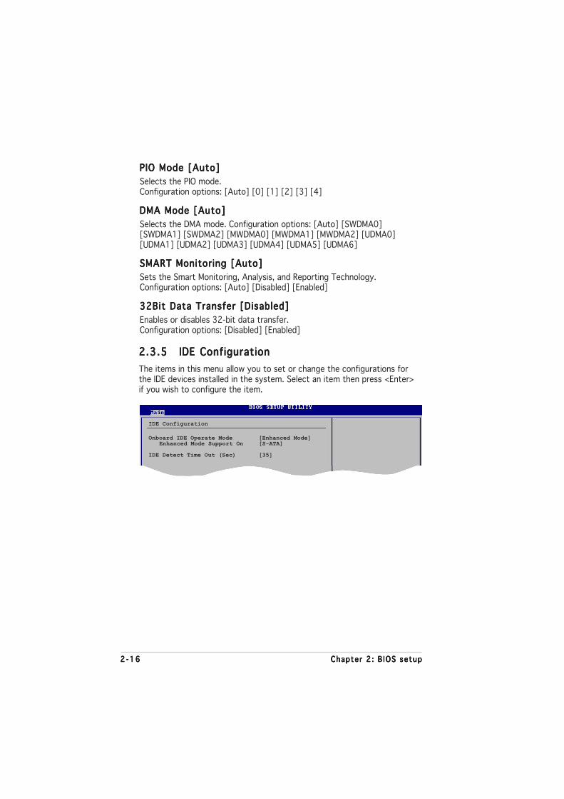
2 -162 -162 -162 -162 -16 Chapter 2 : B IOS setupChapter 2 : B IOS setupChapter 2 : B IOS setupChapter 2 : B IOS setupChapter 2 : B IOS setup
PIO Mode [Auto]PIO Mode [Auto]PIO Mode [Auto]PIO Mode [Auto]PIO Mode [Auto]
Selects the PIO mode.Configuration options: [Auto] [0] [1] [2] [3] [4]
DMA Mode [Auto]DMA Mode [Auto]DMA Mode [Auto]DMA Mode [Auto]DMA Mode [Auto]
Selects the DMA mode. Configuration options: [Auto] [SWDMA0][SWDMA1] [SWDMA2] [MWDMA0] [MWDMA1] [MWDMA2] [UDMA0][UDMA1] [UDMA2] [UDMA3] [UDMA4] [UDMA5] [UDMA6]
SMART Monitoring [Auto]SMART Monitoring [Auto]SMART Monitoring [Auto]SMART Monitoring [Auto]SMART Monitoring [Auto]
Sets the Smart Monitoring, Analysis, and Reporting Technology.Configuration options: [Auto] [Disabled] [Enabled]
32Bit Data Transfer [Disabled]32Bit Data Transfer [Disabled]32Bit Data Transfer [Disabled]32Bit Data Transfer [Disabled]32Bit Data Transfer [Disabled]
Enables or disables 32-bit data transfer.Configuration options: [Disabled] [Enabled]
2.3.52.3.52.3.52.3.52.3.5 IDE ConfigurationIDE ConfigurationIDE ConfigurationIDE ConfigurationIDE Configuration
The items in this menu allow you to set or change the configurations forthe IDE devices installed in the system. Select an item then press <Enter>if you wish to configure the item.
IDE Configuration
Onboard IDE Operate Mode [Enhanced Mode]Enhanced Mode Support On [S-ATA]
IDE Detect Time Out (Sec) [35]

ASUS P5GPL-XASUS P5GPL-XASUS P5GPL-XASUS P5GPL-XASUS P5GPL-X 2 -172 -172 -172 -172 -17
Onboard IDE Operate Mode [Enhanced Mode]Onboard IDE Operate Mode [Enhanced Mode]Onboard IDE Operate Mode [Enhanced Mode]Onboard IDE Operate Mode [Enhanced Mode]Onboard IDE Operate Mode [Enhanced Mode]
Disables or allows selection of the IDE operation mode depending on theinstalled operating system (OS). Set to [Enhanced Mode] if you are usingnative OS including Windows® 2000/XP. Configuration options: [Disabled][Compatible Mode] [Enhanced Mode]
Enhanced Mode Support On [S-ATA]Allows you to use native OS on Serial ATA and Parallel ATA ports. It isrecommend that you do not change the default setting for better OScompatibility. In this setting, you may use legacy OS on the ParallelATA ports only if you do not install any Serial ATA device.
The P-ATA+S-ATA and P-ATA options are for advanced users only. Ifyou set to any of these options and encountered problems, revert tothe default setting S -ATAS-ATAS-ATAS-ATAS-ATA. Configuration options: [S-ATA+P-ATA][S-ATA] [P-ATA]
Combined Mode Option [Primary P-ATA +S-ATA]Allows you to choose the IDE ports to be used. Configuration options:[Primary P-ATA +S-ATA] [S-ATA only] [P-ATA only]
The S-ATA and P-ATA options are for advanced users only. If you setto any of these options and encounter problems, revert to the defaultsetting [Secondary P-ATA+S-ATA]. Configuration options: [S-ATAonly] [P-ATA only] [P-ATA+S-ATA]
The Onboard IDE Operate Mode Onboard IDE Operate Mode Onboard IDE Operate Mode Onboard IDE Operate Mode Onboard IDE Operate Mode and its sub-menu items appearonly when the Conf igure SATA As Conf igure SATA As Conf igure SATA As Conf igure SATA As Conf igure SATA As item is set to [Standard IDE].
IDE Detect Time Out [35]IDE Detect Time Out [35]IDE Detect Time Out [35]IDE Detect Time Out [35]IDE Detect Time Out [35]
Selects the time out value for detecting ATA/ATAPI devices.Configuration options: [0] [5] [10] [15] [20] [25] [30] [35]
The Combined Mode Opt ion i temCombined Mode Opt ion i temCombined Mode Opt ion i temCombined Mode Opt ion i temCombined Mode Opt ion i tem appears only when theOnboard IDE Operate ModeOnboard IDE Operate ModeOnboard IDE Operate ModeOnboard IDE Operate ModeOnboard IDE Operate Mode item is set to [Compatible Mode].

2 -182 -182 -182 -182 -18 Chapter 2 : B IOS setupChapter 2 : B IOS setupChapter 2 : B IOS setupChapter 2 : B IOS setupChapter 2 : B IOS setup
2.3.62.3.62.3.62.3.62.3.6 System InformationSystem InformationSystem InformationSystem InformationSystem Information
This menu gives you an overview of the general system specifications. TheBIOS automatically detects the items in this menu.
AMI BIOSAMI BIOSAMI BIOSAMI BIOSAMI BIOS
Displays the auto-detected BIOS information
ProcessorProcessorProcessorProcessorProcessor
Displays the auto-detected CPU specification
System MemorySystem MemorySystem MemorySystem MemorySystem Memory
Displays the auto-detected system memory
AMIBIOS
Version : 0107
Build Date : 06/27/05
Processor
Type : Genuine Intel(R) CPU 3.20GHz
Speed : 3200 MHz
Count : 1
System Memory
Size : 512MB

ASUS P5GPL-XASUS P5GPL-XASUS P5GPL-XASUS P5GPL-XASUS P5GPL-X 2 -192 -192 -192 -192 -19
2.4 Advanced menu
The Advanced menu items allow you to change the settings for the CPUand other system devices.
Take caution when changing the settings of the Advanced menu items.Incorrect field values can cause the system to malfunction.
Configure CPU.JumperFree ConfigurationUSB Configuration
CPU ConfigurationChipsetOnboard Devices ConfigurationPCI PnP
2.4.12.4.12.4.12.4.12.4.1 JumperFree ConfigurationJumperFree ConfigurationJumperFree ConfigurationJumperFree ConfigurationJumperFree Configuration
AI Overclocking [Auto]AI Overclocking [Auto]AI Overclocking [Auto]AI Overclocking [Auto]AI Overclocking [Auto]
Allows selection of CPU overclocking options to achieve desired CPUinternal frequency. Select either one of the preset overclockingconfiguration options:
Manua l Manua l Manua l Manua l Manua l - allows you to individually set overclocking parameters.
Standard Standard Standard Standard Standard - loads the standard settings for the system.
Auto Auto Auto Auto Auto - loads the optimal settings for the system.
Overc lock Prof i le Overc lock Prof i le Overc lock Prof i le Overc lock Prof i le Overc lock Prof i le - loads overclocking profiles with optimal parametersfor stability when overclocking.
Overclock Options [Overclock 5%]Overclock Options [Overclock 5%]Overclock Options [Overclock 5%]Overclock Options [Overclock 5%]Overclock Options [Overclock 5%]
Allows you to set the oveclocking options. Configuration options:[Overclock 5%] [Overclock 10%] [Overclock 15%] [Overclock 20%][Overclock 30%] [FSB900/DDR1-450] [FSB1000/DDR1-500]
Configure System Frequency/Voltage
AI Overclocking [Auto]CPU Clock Free [Auto]
The following items also appear when the AI Overclocking item is set to[Overclock Profile].

2 -202 -202 -202 -202 -20 Chapter 4 : B IOS setupChapter 4 : B IOS setupChapter 4 : B IOS setupChapter 4 : B IOS setupChapter 4 : B IOS setup
CPU Frequency [XXX]CPU Frequency [XXX]CPU Frequency [XXX]CPU Frequency [XXX]CPU Frequency [XXX]
Displays the frequency sent by the clock generator to the system bus andPCI bus. The value of this item is auto-detected by the BIOS. Use the <+><+><+><+><+>and < ->< ->< ->< ->< -> keys to adjust the CPU frequency. You can also type the desiredCPU frequency using the numeric keypad. The values range from 100 to450. Refer to the table below for the correct Front Side Bus and CPUExternal Frequency settings.
CPU Lock Free [Auto]CPU Lock Free [Auto]CPU Lock Free [Auto]CPU Lock Free [Auto]CPU Lock Free [Auto]
Allows you to adjust the CPU multiplier to 14x. Setting this item to [Auto]allows the motherboard to automatically reduce the CPU multiplier value formore flexibility when increasing the external FSB.Configuration options: [Auto] [Disabled] [Enabled]
PCI Clock Synchronization Mode [Auto]PCI Clock Synchronization Mode [Auto]PCI Clock Synchronization Mode [Auto]PCI Clock Synchronization Mode [Auto]PCI Clock Synchronization Mode [Auto]
Selects the PCI Clock Synchronization mode.Configuration options: [Auto] [33.33MHz] [To CPU]
CPU VCore Voltage [Auto]CPU VCore Voltage [Auto]CPU VCore Voltage [Auto]CPU VCore Voltage [Auto]CPU VCore Voltage [Auto]
Allows selection of the CPU VCore voltage. The configuration options varydepending on the CPU installed. Setting to Auto allows the BIOS to detectthe VCore voltage of the CPU installed.
Refer to the CPU documentation before setting the CPU VCore voltage. Avery high Vcore voltage can severely damage the CPU!
F ron t S i de BusF ron t S i de BusF ron t S i de BusF ron t S i de BusF ron t S i de Bus CPU Ex te rna l F r equencyCPU Ex te rna l F r equencyCPU Ex te rna l F r equencyCPU Ex te rna l F r equencyCPU Ex te rna l F r equency
FSB 800 200 MHz
FSB 533 133 MHz
FSB/CPU External Frequency Synchronizat ionFSB/CPU External Frequency Synchronizat ionFSB/CPU External Frequency Synchronizat ionFSB/CPU External Frequency Synchronizat ionFSB/CPU External Frequency Synchronizat ion
DRAM Frequency [Auto]DRAM Frequency [Auto]DRAM Frequency [Auto]DRAM Frequency [Auto]DRAM Frequency [Auto]
Allows you to set the DDR operating frequency.Configuration options: [Auto] [333MHz] [400MHz]
Selecting a very high DRAM frequency may cause the system to becomeunstable! If this happens, revert to the default setting.
The following item appears only when you install a CPU that supports thelock free feature. Only some latest CPUs support this feature.

ASUS P5GPL-XASUS P5GPL-XASUS P5GPL-XASUS P5GPL-XASUS P5GPL-X 2 -212 -212 -212 -212 -21
USB Function [Enabled]USB Function [Enabled]USB Function [Enabled]USB Function [Enabled]USB Function [Enabled]
Allows you to enable or disable the USB function.Configuration options: [Disabled] [Enabled]
Legacy USB Support [Auto]Legacy USB Support [Auto]Legacy USB Support [Auto]Legacy USB Support [Auto]Legacy USB Support [Auto]
Allows you to enable or disable support for USB devices on legacyoperating systems (OS). Setting to Auto allows the system to detect thepresence of USB devices at startup. If detected, the USB controller legacymode is enabled. If no USB device is detected, the legacy USB support isdisabled. Configuration options: [Disabled] [Enabled] [Auto]
USB 2.0 Controller [Enabled]USB 2.0 Controller [Enabled]USB 2.0 Controller [Enabled]USB 2.0 Controller [Enabled]USB 2.0 Controller [Enabled]
Allows you to enable or disable the USB 2.0 controller.Configuration options: [Disabled] [Enabled]
USB 2.0 Controller Mode [HiSpeed]USB 2.0 Controller Mode [HiSpeed]USB 2.0 Controller Mode [HiSpeed]USB 2.0 Controller Mode [HiSpeed]USB 2.0 Controller Mode [HiSpeed]
Allows you to configure the USB 2.0 controller in HiSpeed (480 Mbps) orFull Speed (12 Mbps). Configuration options: [HiSpeed] [Full Speed]
BIOS EHCI Hand-off [Disabled]BIOS EHCI Hand-off [Disabled]BIOS EHCI Hand-off [Disabled]BIOS EHCI Hand-off [Disabled]BIOS EHCI Hand-off [Disabled]
Allows you to enable support for operating systems without an EHCIhand-off feature. Configuration options: [Enabled] [Disabled]
The Module Version and USB Devices Enabled items show theauto-detected values. If no USB device is detected, the item showsNone.
2.4.22.4.22.4.22.4.22.4.2 USB ConfigurationUSB ConfigurationUSB ConfigurationUSB ConfigurationUSB Configuration
The items in this menu allows you to change the USB-related features.Select an item then press <Enter> to display the configuration options.
USB Configuration
Module Version - 2.24.0-10.4
USB Devices Enabled: None
USB Function [Enabled]Legacy USB Support [Auto]USB 2.0 Controller [Enabled]USB 2.0 Controller Mode [HiSpeed]BIOS EHCI Hand-Off [Enabled]
Do not disable the BIOS EHCI Hand-Off option if you are running aWindows® operating system with USB device.

2 -222 -222 -222 -222 -22 Chapter 4 : B IOS setupChapter 4 : B IOS setupChapter 4 : B IOS setupChapter 4 : B IOS setupChapter 4 : B IOS setup
2.4.32.4.32.4.32.4.32.4.3 CPU ConfigurationCPU ConfigurationCPU ConfigurationCPU ConfigurationCPU Configuration
The items in this menu show the CPU-related information that the BIOSautomatically detects.
Select Screen Select Item+- Change OptionF1 General HelpF10 Save and ExitESC Exit
Configure Advanced CPU settings
Manufacturer: IntelBrand String: Genuine Intel(R) CPU 3.20GHzFrequency : 3200 MHzFSB Speed : 800 MHz
Cache L1 : 16 KBCache L2 : 1024 KBCache L3 : 0 KBRatio Status: Unlocked (Max:16, Min:14)Ratio Actual Value : 16 Ratio CMOS Setting: [ 18] VID CMOS Setting: [ 18]CPU Clock Free [Auto]Max CPUID Value Limit: [Disabled]Execute Disable Function [Disabled]Enhanced C1 Control [Auto]Hardware Prefetcher [Enabled]Adjacent Cache Line Prefetch [Enabled]CPU Internal Thermal Control [Auto]
Sets the ratio betweenCPU Core Clock and theFSB Frequency.NOTE: If an invalidratio is set in CMOSthen actual andsetpoint values maydiffer.
Ratio CMOS Setting [ 18]Ratio CMOS Setting [ 18]Ratio CMOS Setting [ 18]Ratio CMOS Setting [ 18]Ratio CMOS Setting [ 18]
Sets the ratio between the CPU Core Clock and the Front Side Busfrequency. The default value of this item is auto-detected by BIOS. Use the<+> or <-> keys to adjust the values.
VID CMOS Setting [ 62]VID CMOS Setting [ 62]VID CMOS Setting [ 62]VID CMOS Setting [ 62]VID CMOS Setting [ 62]Allows you to set the VID CMOS setting at which the processor is to run.The BIOS auto-detects the default value of this item. Use the <+> or <->keys to adjust the values.
CPU Lock Free [Auto]CPU Lock Free [Auto]CPU Lock Free [Auto]CPU Lock Free [Auto]CPU Lock Free [Auto]Allows you to adjust the CPU multiplier to 14x. Setting this item to [Auto]allows the motherboard to automatically reduce the CPU multiplier value formore flexibility when increasing the external FSB. This item appears onlywhen you install a processor with CPU Lock Free feature.Configuration options: [Auto] [Disabled] [Enabled]
Max CPUID Value Limit [Disabled]Max CPUID Value Limit [Disabled]Max CPUID Value Limit [Disabled]Max CPUID Value Limit [Disabled]Max CPUID Value Limit [Disabled]Enable this item to boot legacy operating systems that cannot supportCPUs with extended CPUID functions.Configuration options: [Disabled] [Enabled]
Execute Disable Function [Disabled]Execute Disable Function [Disabled]Execute Disable Function [Disabled]Execute Disable Function [Disabled]Execute Disable Function [Disabled]Enables or disables the Execute Disable function. This item appears onlywhen you install a processor with the Execute Disable function.Configuration options: [Disabled] [Enabled]
pF10 Save and ExitESC ExitHyper Threading Technology [Enabled]
Intel(R) SpeedStep(tm) Tech. [Automatic]

ASUS P5GPL-XASUS P5GPL-XASUS P5GPL-XASUS P5GPL-XASUS P5GPL-X 2 -232 -232 -232 -232 -23
Enhanced C1 Control [Auto]Enhanced C1 Control [Auto]Enhanced C1 Control [Auto]Enhanced C1 Control [Auto]Enhanced C1 Control [Auto]
When set to [Auto], the BIOS will automatically check the CPU’s capabilityto enable the C1E support. In C1E mode, the CPU power consumption islower when idle. Configuration options: [Auto] [Disabled]
Hardware Prefetcher [Enabled]Hardware Prefetcher [Enabled]Hardware Prefetcher [Enabled]Hardware Prefetcher [Enabled]Hardware Prefetcher [Enabled]
Enables or disables the Hardware Prefetcher feature.Configuration options: [Disabled] [Enabled]
Adjacent Cache Line Prefetch [Enabled]Adjacent Cache Line Prefetch [Enabled]Adjacent Cache Line Prefetch [Enabled]Adjacent Cache Line Prefetch [Enabled]Adjacent Cache Line Prefetch [Enabled]
Enables or disables the Adjacent Cache Line Prefetch feature.Configuration options: [Disabled] [Enabled]
CPU Internal Thermal Control [Auto]CPU Internal Thermal Control [Auto]CPU Internal Thermal Control [Auto]CPU Internal Thermal Control [Auto]CPU Internal Thermal Control [Auto]
Disables or sets the CPU internal thermal control.Configuration options: [Disabled] [Auto]
Hyper-Threading Technology [Enabled]Hyper-Threading Technology [Enabled]Hyper-Threading Technology [Enabled]Hyper-Threading Technology [Enabled]Hyper-Threading Technology [Enabled]
Allows you to enable or disable the processor Hyper-Threading Technology.Configuration options: [Disabled] [Enabled]
The following item appears only when you installed an Intel® Pentium® 4CPU that supports the Enhanced Intel SpeedStep® Technology (EIST).
Intel(R) SpeedStep Technology [Automatic]Intel(R) SpeedStep Technology [Automatic]Intel(R) SpeedStep Technology [Automatic]Intel(R) SpeedStep Technology [Automatic]Intel(R) SpeedStep Technology [Automatic]
Allows you to use the Enhanced Intel® SpeedStep® Technology. When setto [Automatic], you can adjust the system power settings in the operatingsystem to use the EIST feature. Set this item to [Disabled] if you do notwant to use the EIST. Configuration options: [Automatic] [Disabled]
2.4.42.4.42.4.42.4.42.4.4 ChipsetChipsetChipsetChipsetChipset
The Chipset menu allows you to change the advanced chipset settings.Select an item then press <Enter> to display the sub-menu.
Advanced Chipset Settings
Configure DRAM Timing by SPD [Enabled]Hyper Path 2 [Auto]
Graphic Adapter Priority [PCI Express/PCI]Pre-allocated Graphics Memory [Enabled, 8MB] Graphics memory type [Auto]
• Refer to the Appendix for details on how to use the EIST feature.
• The motherboard comes with a BIOS file that supports EIST.

2 -242 -242 -242 -242 -24 Chapter 4 : B IOS setupChapter 4 : B IOS setupChapter 4 : B IOS setupChapter 4 : B IOS setupChapter 4 : B IOS setup
Advanced Chipset SettingsAdvanced Chipset SettingsAdvanced Chipset SettingsAdvanced Chipset SettingsAdvanced Chipset Settings
Configure DRAM Timing by SPD [Enabled]Configure DRAM Timing by SPD [Enabled]Configure DRAM Timing by SPD [Enabled]Configure DRAM Timing by SPD [Enabled]Configure DRAM Timing by SPD [Enabled]When this item is enabled, the DRAM timing parameters are set accordingto the DRAM SPD (Serial Presence Detect). When disabled, you canmanually set the DRAM timing parameters through the DRAM sub-items.The following sub-items appear when this item is Disabled.Configuration options: [Disabled] [Enabled]
DRAM CAS# Latency [3 Clocks]Controls the latency between the SDRAM read command and the timethe data actually becomes available.Configuration options: [3 Clocks] [2.5 Clocks] [2 Clocks]DRAM RAS# Precharge [4 Clocks]Controls the idle clocks after issuing a precharge command to the DDRSDRAM. Configuration options: [2 Clocks] [3 Clocks] [4 Clocks][5 Clocks]DRAM RAS# to CAS# Delay [4 Clocks]Controls the latency between the DDR SDRAM active command andthe read/write command. Configuration options: [2 Clocks] [3 Clocks][4 Clocks] [5 Clocks]DRAM RAS# Activate to Precharge [15 Clocks]Sets the RAS Activate timing to Precharge timing.Configuration options: [4 Clocks] ~ [15 Clocks]
Hyper Path 2 [Auto]Hyper Path 2 [Auto]Hyper Path 2 [Auto]Hyper Path 2 [Auto]Hyper Path 2 [Auto]
Enables or disables the memory acceleration mode feature.Configuration options: [Disabled] [Enabled] [Auto]
Graphic Adapter Priority [PCI Express/PCI]Graphic Adapter Priority [PCI Express/PCI]Graphic Adapter Priority [PCI Express/PCI]Graphic Adapter Priority [PCI Express/PCI]Graphic Adapter Priority [PCI Express/PCI]
Allows selection of the graphics controller to use as primary boot device.Configuration options: [PCI Express/PCI] [PCI/PCI Express]
PEG Buffer Length [Auto]PEG Buffer Length [Auto]PEG Buffer Length [Auto]PEG Buffer Length [Auto]PEG Buffer Length [Auto]
Sets the PCI Express Graphics card buffer length.Configuration options: [Auto] [Long] [Short]
Link Latency [Auto]Link Latency [Auto]Link Latency [Auto]Link Latency [Auto]Link Latency [Auto]
Sets the link latency. Configuration options: [Auto] [Slow] [Normal]
PEG Link Mode [Auto]PEG Link Mode [Auto]PEG Link Mode [Auto]PEG Link Mode [Auto]PEG Link Mode [Auto]
Sets the PCI Express Graphics link mode.Configuration options: [Auto] [Slow] [Normal] [Fast] [Faster]
PEG Root Control [Auto]PEG Root Control [Auto]PEG Root Control [Auto]PEG Root Control [Auto]PEG Root Control [Auto]
Enables or disables the PCI Express Graphics root control.Configuration options: [Auto] [Disabled] [Enabled]
Slot Power [Auto]Slot Power [Auto]Slot Power [Auto]Slot Power [Auto]Slot Power [Auto]
Sets the slot operating power.Configuration options: [Auto] [Light] [Normal] [Heavy] [Heavier]

ASUS P5GPL-XASUS P5GPL-XASUS P5GPL-XASUS P5GPL-XASUS P5GPL-X 2 -252 -252 -252 -252 -25
2.4.52.4.52.4.52.4.52.4.5 Onboard Devices ConfigurationOnboard Devices ConfigurationOnboard Devices ConfigurationOnboard Devices ConfigurationOnboard Devices Configuration
Configure Win627EHF Super IO Chipset
HD Audio Controller [Enabled]Onboard LAN [Enabled]LAN Option ROM [Disabled]
Serial Port1 Address [3F8/IRQ4]Parallel Port Address [378]Parallel Port Mode [ECP]
ECP Mode DMA Channel [DMA3] Parallel Port IRQ [IRQ7]
HD Audio Controller [Enabled]HD Audio Controller [Enabled]HD Audio Controller [Enabled]HD Audio Controller [Enabled]HD Audio Controller [Enabled]
Enables or disables the High Definition/AC’97 CODEC.Configuration options: [Enabled] [Disabled]
OnBoard LAN [Enabled]OnBoard LAN [Enabled]OnBoard LAN [Enabled]OnBoard LAN [Enabled]OnBoard LAN [Enabled]
Allows you to enable or disable the onboard PCI Express Gigabit LANcontroller. Configuration options: [Disabled] [Enabled]
LAN Option ROM [Disabled]LAN Option ROM [Disabled]LAN Option ROM [Disabled]LAN Option ROM [Disabled]LAN Option ROM [Disabled]
This item allows you to enable or disable the option ROM in the onboardLAN controller. This item appears only when the Onboard LAN item is setto Enabled. Configuration options:[Disabled] [Enabled]
Serial Port1 Address [3F8/IRQ4]Serial Port1 Address [3F8/IRQ4]Serial Port1 Address [3F8/IRQ4]Serial Port1 Address [3F8/IRQ4]Serial Port1 Address [3F8/IRQ4]
Allows you to select the Serial Port1 base address.Configuration options: [Disabled] [3F8/IRQ4] [2F8/IRQ3] [3E8/IRQ4][2E8/IRQ3]
Parallel Port Address [378]Parallel Port Address [378]Parallel Port Address [378]Parallel Port Address [378]Parallel Port Address [378]
Allows you to select the Parallel Port base addresses.Configuration options: [Disabled] [378] [278] [3BC]
Parallel Port Mode [ECP]Parallel Port Mode [ECP]Parallel Port Mode [ECP]Parallel Port Mode [ECP]Parallel Port Mode [ECP]
Allows you to select the Parallel Port mode.Configuration options: [Normal] [Bi-directional] [EPP] [ECP]
ECP Mode DMA Channe l [DMA3]ECP Mode DMA Channe l [DMA3]ECP Mode DMA Channe l [DMA3]ECP Mode DMA Channe l [DMA3]ECP Mode DMA Channe l [DMA3]
Appears only when the Parallel Port Mode is set to [ECP]. This itemallows you to set the Parallel Port ECP DMA.Configuration options: [DMA0] [DMA1] [DMA3]
Parallel Port IRQ [IRQ7]Configuration options: [IRQ5] [IRQ7]
Onboard Game/MIDI Port [Disabled]Onboard Game/MIDI Port [Disabled]Onboard Game/MIDI Port [Disabled]Onboard Game/MIDI Port [Disabled]Onboard Game/MIDI Port [Disabled]
Allows you to select the Game Port address or to disable the port.Configuration options: [Disabled] [200/300] [200/330] [208/300] [208/330]
Enable or DisableHigh Definition AudioController

2 -262 -262 -262 -262 -26 Chapter 4 : B IOS setupChapter 4 : B IOS setupChapter 4 : B IOS setupChapter 4 : B IOS setupChapter 4 : B IOS setup
2.4.62.4.62.4.62.4.62.4.6 PCI PnPPCI PnPPCI PnPPCI PnPPCI PnP
The PCI PnP menu items allow you to change the advanced settings forPCI/PnP devices. The menu includes setting IRQ and DMA channel resourcesfor either PCI/PnP or legacy ISA devices, and setting the memory size blockfor legacy ISA devices.
Take caution when changing the settings of the PCI PnP menu items.Incorrect field values can cause the system to malfunction.
Select Screen Select Item+- Change OptionF1 General HelpF10 Save and ExitESC Exit
Advanced PCI/PnP Settings
WARNING: Setting wrong values in below sections may cause system to malfunction.
Plug And Play O/S [No]PCI Latency Timer [64]Allocate IRQ to PCI VGA [Yes]Palette Snooping [Disabled]
IRQ-3 assigned to [PCI Device]IRQ-4 assigned to [PCI Device]IRQ-5 assigned to [PCI Device]IRQ-7 assigned to [PCI Device]IRQ-9 assigned to [PCI Device]IRQ-10 assigned to [PCI Device]IRQ-11 assigned to [PCI Device]IRQ-14 assigned to [PCI Device]IRQ-15 assigned to [PCI Device]
Plug and Play O/S [No]Plug and Play O/S [No]Plug and Play O/S [No]Plug and Play O/S [No]Plug and Play O/S [No]
When set to [No], BIOS configures all the devices in the system. When setto [Yes] and if you install a Plug and Play operating system, the operatingsystem configures the Plug and Play devices not required for boot.Configuration options: [No] [Yes]
PCI Latency Timer [64]PCI Latency Timer [64]PCI Latency Timer [64]PCI Latency Timer [64]PCI Latency Timer [64]
Allows you to select the value in units of PCI clocks for the PCI devicelatency timer register. Configuration options: [32] [64] [96] [128] [160][192] [224] [248]
Allocate IRQ to PCI VGA [Yes]Allocate IRQ to PCI VGA [Yes]Allocate IRQ to PCI VGA [Yes]Allocate IRQ to PCI VGA [Yes]Allocate IRQ to PCI VGA [Yes]
When set to [Yes], BIOS assigns an IRQ to PCI VGA card if the cardrequests for an IRQ. When set to [No], BIOS does not assign an IRQ to thePCI VGA card even if requested. Configuration options: [No] [Yes]
Palette Snooping [Disabled]Palette Snooping [Disabled]Palette Snooping [Disabled]Palette Snooping [Disabled]Palette Snooping [Disabled]
When set to [Enabled], the pallete snooping feature informs the PCIdevices that an ISA graphics device is installed in the system so that thelatter can function correctly. Configuration options: [Disabled] [Enabled]
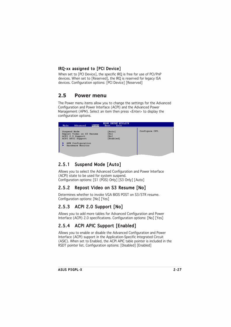
ASUS P5GPL-XASUS P5GPL-XASUS P5GPL-XASUS P5GPL-XASUS P5GPL-X 2 -272 -272 -272 -272 -27
2.5 Power menu
The Power menu items allow you to change the settings for the AdvancedConfiguration and Power Interface (ACPI) and the Advanced PowerManagement (APM). Select an item then press <Enter> to display theconfiguration options.
2.5.12.5.12.5.12.5.12.5.1 Suspend Mode [Auto]Suspend Mode [Auto]Suspend Mode [Auto]Suspend Mode [Auto]Suspend Mode [Auto]
Allows you to select the Advanced Configuration and Power Interface(ACPI) state to be used for system suspend.Configuration options: [S1 (POS) Only] [S3 Only] [Auto]
2.5.22.5.22.5.22.5.22.5.2 Repost Video on S3 Resume [No]Repost Video on S3 Resume [No]Repost Video on S3 Resume [No]Repost Video on S3 Resume [No]Repost Video on S3 Resume [No]
Determines whether to invoke VGA BIOS POST on S3/STR resume.Configuration options: [No] [Yes]
2.5.32.5.32.5.32.5.32.5.3 ACPI 2.0 Support [No]ACPI 2.0 Support [No]ACPI 2.0 Support [No]ACPI 2.0 Support [No]ACPI 2.0 Support [No]
Allows you to add more tables for Advanced Configuration and PowerInterface (ACPI) 2.0 specifications. Configuration options: [No] [Yes]
2.5.42.5.42.5.42.5.42.5.4 ACPI APIC Support [Enabled]ACPI APIC Support [Enabled]ACPI APIC Support [Enabled]ACPI APIC Support [Enabled]ACPI APIC Support [Enabled]
Allows you to enable or disable the Advanced Configuration and PowerInterface (ACPI) support in the Application-Specific Integrated Circuit(ASIC). When set to Enabled, the ACPI APIC table pointer is included in theRSDT pointer list. Configuration options: [Disabled] [Enabled]
Configure CPU.Suspend Mode [Auto]Repost Video on S3 Resume [No]ACPI 2.0 Support [No]ACPI APIC Support [Enabled]
APM ConfigurationHardware Monitor
IRQ-xx assigned to [PCI Device]IRQ-xx assigned to [PCI Device]IRQ-xx assigned to [PCI Device]IRQ-xx assigned to [PCI Device]IRQ-xx assigned to [PCI Device]
When set to [PCI Device], the specific IRQ is free for use of PCI/PnPdevices. When set to [Reserved], the IRQ is reserved for legacy ISAdevices. Configuration options: [PCI Device] [Reserved]
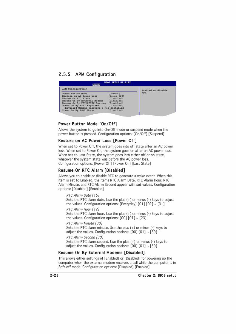
2 -282 -282 -282 -282 -28 Chapter 2 : B IOS setupChapter 2 : B IOS setupChapter 2 : B IOS setupChapter 2 : B IOS setupChapter 2 : B IOS setup
2.5.52.5.52.5.52.5.52.5.5 APM ConfigurationAPM ConfigurationAPM ConfigurationAPM ConfigurationAPM Configuration
Enabled or disableAPM.
APM Configuration
Power button Mode [On/Off]Restore on AC Power Loss [Power Off]Resume On RTC Alarm [Disabled]Resume On By External Modems [Disabled]Resume On By PCI/PCIEX Devices [Disabled]Power On By PS/2 Keyboard [Disabled] Keyboard Wakeup Password : Not InstalledPower On By PS/2 Mouse [Disabled]
Power Button Mode [On/Off]Power Button Mode [On/Off]Power Button Mode [On/Off]Power Button Mode [On/Off]Power Button Mode [On/Off]
Allows the system to go into On/Off mode or suspend mode when thepower button is pressed. Configuration options: [On/Off] [Suspend]
Restore on AC Power Loss [Power Off]Restore on AC Power Loss [Power Off]Restore on AC Power Loss [Power Off]Restore on AC Power Loss [Power Off]Restore on AC Power Loss [Power Off]
When set to Power Off, the system goes into off state after an AC powerloss. When set to Power On, the system goes on after an AC power loss.When set to Last State, the system goes into either off or on state,whatever the system state was before the AC power loss.Configuration options: [Power Off] [Power On] [Last State]
Resume On RTC Alarm [Disabled]Resume On RTC Alarm [Disabled]Resume On RTC Alarm [Disabled]Resume On RTC Alarm [Disabled]Resume On RTC Alarm [Disabled]
Allows you to enable or disable RTC to generate a wake event. When thisitem is set to Enabled, the items RTC Alarm Date, RTC Alarm Hour, RTCAlarm Minute, and RTC Alarm Second appear with set values. Configurationoptions: [Disabled] [Enabled]
RTC Alarm Date [15]Sets the RTC alarm date. Use the plus (+) or minus (-) keys to adjustthe values. Configuration options: [Everyday] [01] [02] ~ [31]
RTC Alarm Hour [12]Sets the RTC alarm hour. Use the plus (+) or minus (-) keys to adjustthe values. Configuration options: [00] [01] ~ [23]
RTC Alarm Minute [30]Sets the RTC alarm minute. Use the plus (+) or minus (-) keys toadjust the values. Configuration options: [00] [01] ~ [59]
RTC Alarm Second [30]Sets the RTC alarm second. Use the plus (+) or minus (-) keys toadjust the values. Configuration options: [00] [01] ~ [59]
Resume On By External Modems [Disabled]Resume On By External Modems [Disabled]Resume On By External Modems [Disabled]Resume On By External Modems [Disabled]Resume On By External Modems [Disabled]
This allows either settings of [Enabled] or [Disabled] for powering up thecomputer when the external modem receives a call while the computer is inSoft-off mode. Configuration options: [Disabled] [Enabled]

ASUS P5GPL-XASUS P5GPL-XASUS P5GPL-XASUS P5GPL-XASUS P5GPL-X 2 -292 -292 -292 -292 -29
Resume On By PCI/PCIEX Devices [Disabled]Resume On By PCI/PCIEX Devices [Disabled]Resume On By PCI/PCIEX Devices [Disabled]Resume On By PCI/PCIEX Devices [Disabled]Resume On By PCI/PCIEX Devices [Disabled]
When set to [Enabled], this parameter allows you to turn on the systemthrough a PME# device. This feature requires an ATX power supply thatprovides at least 1A on the +5VSB lead.Configuration options: [Disabled] [Enabled]
Power On By PS/2 Keyboard [Disabled]Power On By PS/2 Keyboard [Disabled]Power On By PS/2 Keyboard [Disabled]Power On By PS/2 Keyboard [Disabled]Power On By PS/2 Keyboard [Disabled]
Allows you to use specific keys on the keyboard to turn on the system.This feature requires an ATX power supply that provides at least 1A on the+5VSB lead. Configuration options: [Disabled] [Enabled]
Wakeup PasswordWakeup PasswordWakeup PasswordWakeup PasswordWakeup Password
This item appears only when the Power On By PS/2 Keyboard is set toEnabled. Select this item to set or change the keyboard wakeup password.The Keyboard Wakeup PasswordKeyboard Wakeup PasswordKeyboard Wakeup PasswordKeyboard Wakeup PasswordKeyboard Wakeup Password item that appears below shows thedefault Not Insta l ledNot Insta l ledNot Insta l ledNot Insta l ledNot Insta l led. After you have set a password, this item showsInsta l ledInsta l ledInsta l ledInsta l ledInsta l led.
Power On By PS/2 Mouse [Disabled]Power On By PS/2 Mouse [Disabled]Power On By PS/2 Mouse [Disabled]Power On By PS/2 Mouse [Disabled]Power On By PS/2 Mouse [Disabled]
When set to [Enabled], this parameter allows you to use the PS/2 mouseto turn on the system. This feature requires an ATX power supply thatprovides at least 1A on the +5VSB lead.Configuration options: [Disabled] [Enabled]
The computer cannot receive or transmit data until the computer andapplications are fully running. Thus, connection cannot be made on thefirst try. Turning an external modem off and then back on while thecomputer is off causes an initialization string that turns the systempower on.
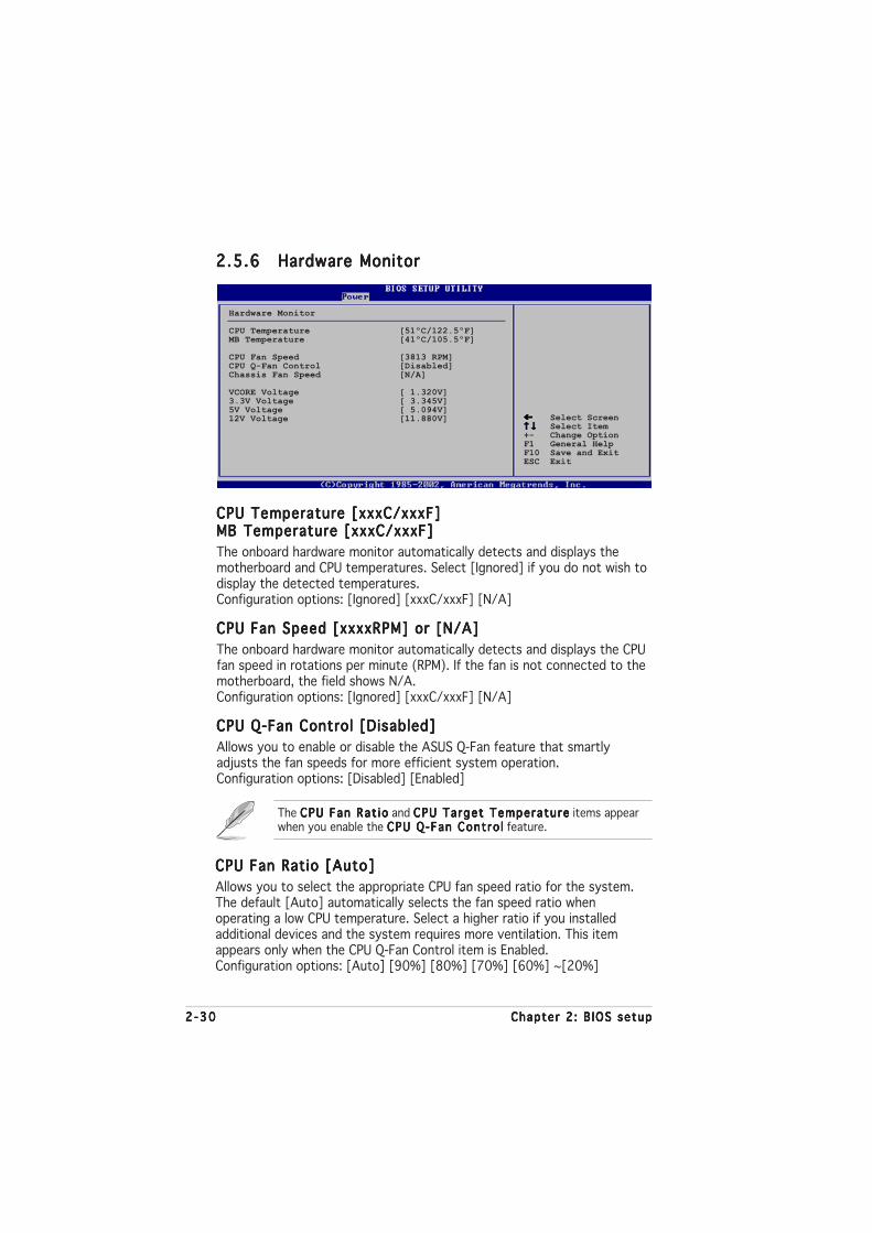
2 -302 -302 -302 -302 -30 Chapter 2 : B IOS setupChapter 2 : B IOS setupChapter 2 : B IOS setupChapter 2 : B IOS setupChapter 2 : B IOS setup
2.5.62.5.62.5.62.5.62.5.6 Hardware MonitorHardware MonitorHardware MonitorHardware MonitorHardware Monitor
Select Screen Select Item+- Change OptionF1 General HelpF10 Save and ExitESC Exit
Hardware Monitor
CPU Temperature [51ºC/122.5ºF]MB Temperature [41ºC/105.5ºF]
CPU Fan Speed [3813 RPM]CPU Q-Fan Control [Disabled]Chassis Fan Speed [N/A]
VCORE Voltage [ 1.320V]3.3V Voltage [ 3.345V]5V Voltage [ 5.094V]12V Voltage [11.880V]
CPU Temperature [xxxC/xxxF]CPU Temperature [xxxC/xxxF]CPU Temperature [xxxC/xxxF]CPU Temperature [xxxC/xxxF]CPU Temperature [xxxC/xxxF]MB Temperature [xxxC/xxxF]MB Temperature [xxxC/xxxF]MB Temperature [xxxC/xxxF]MB Temperature [xxxC/xxxF]MB Temperature [xxxC/xxxF]
The onboard hardware monitor automatically detects and displays themotherboard and CPU temperatures. Select [Ignored] if you do not wish todisplay the detected temperatures.Configuration options: [Ignored] [xxxC/xxxF] [N/A]
CPU Fan Speed [xxxxRPM] or [N/A]CPU Fan Speed [xxxxRPM] or [N/A]CPU Fan Speed [xxxxRPM] or [N/A]CPU Fan Speed [xxxxRPM] or [N/A]CPU Fan Speed [xxxxRPM] or [N/A]
The onboard hardware monitor automatically detects and displays the CPUfan speed in rotations per minute (RPM). If the fan is not connected to themotherboard, the field shows N/A.Configuration options: [Ignored] [xxxC/xxxF] [N/A]
CPU Q-Fan Control [Disabled]CPU Q-Fan Control [Disabled]CPU Q-Fan Control [Disabled]CPU Q-Fan Control [Disabled]CPU Q-Fan Control [Disabled]
Allows you to enable or disable the ASUS Q-Fan feature that smartlyadjusts the fan speeds for more efficient system operation.Configuration options: [Disabled] [Enabled]
The CPU Fan Rat ioCPU Fan Rat ioCPU Fan Rat ioCPU Fan Rat ioCPU Fan Rat io and CPU Target TemperatureCPU Target TemperatureCPU Target TemperatureCPU Target TemperatureCPU Target Temperature items appearwhen you enable the CPU Q-Fan Contro lCPU Q-Fan Contro lCPU Q-Fan Contro lCPU Q-Fan Contro lCPU Q-Fan Contro l feature.
CPU Fan Ratio [Auto]CPU Fan Ratio [Auto]CPU Fan Ratio [Auto]CPU Fan Ratio [Auto]CPU Fan Ratio [Auto]
Allows you to select the appropriate CPU fan speed ratio for the system.The default [Auto] automatically selects the fan speed ratio whenoperating a low CPU temperature. Select a higher ratio if you installedadditional devices and the system requires more ventilation. This itemappears only when the CPU Q-Fan Control item is Enabled.Configuration options: [Auto] [90%] [80%] [70%] [60%] ~[20%]

ASUS P5GPL-XASUS P5GPL-XASUS P5GPL-XASUS P5GPL-XASUS P5GPL-X 2 -312 -312 -312 -312 -31
2.6 Boot menu
The Boot menu items allow you to change the system boot options. Selectan item then press <Enter> to display the sub-menu.
Select Screen Select ItemEnter Go to Sub-screenF1 General HelpF10 Save and ExitESC Exit
APM Configuration
Boot Device Priority
Boot Settings ConfigurationSecurity
CPU Target Temperature [xxxºC]CPU Target Temperature [xxxºC]CPU Target Temperature [xxxºC]CPU Target Temperature [xxxºC]CPU Target Temperature [xxxºC]
Allows you to set the CPU temperature threshold when the CPU fan speedis increased to lower the CPU temperature. This item appears only whenthe CPU Q-Fan Control item is Enabled. The configuration options varydepending on the CPU installed.
Chassis Fan Speed [xxxxRPM] or [N/A]Chassis Fan Speed [xxxxRPM] or [N/A]Chassis Fan Speed [xxxxRPM] or [N/A]Chassis Fan Speed [xxxxRPM] or [N/A]Chassis Fan Speed [xxxxRPM] or [N/A]
The onboard hardware monitor automatically detects and displays thechassis fan speed in rotations per minute (RPM). If the fan is not connectedto the chassis, the specific field shows N/A.Configuration options: [Ignored] [N/A]
VCORE Voltage, 3.3V Voltage, 5V Voltage, 12V VoltageVCORE Voltage, 3.3V Voltage, 5V Voltage, 12V VoltageVCORE Voltage, 3.3V Voltage, 5V Voltage, 12V VoltageVCORE Voltage, 3.3V Voltage, 5V Voltage, 12V VoltageVCORE Voltage, 3.3V Voltage, 5V Voltage, 12V Voltage
The onboard hardware monitor automatically detects the voltage outputthrough the onboard voltage regulators.Configuration options: [Ignored] [X.XXXV]

2 -322 -322 -322 -322 -32 Chapter 2 : B IOS setupChapter 2 : B IOS setupChapter 2 : B IOS setupChapter 2 : B IOS setupChapter 2 : B IOS setup
2.6.12.6.12.6.12.6.12.6.1 Boot Device PriorityBoot Device PriorityBoot Device PriorityBoot Device PriorityBoot Device Priority
1st ~ xxth Boot Device [1st Floppy Drive]1st ~ xxth Boot Device [1st Floppy Drive]1st ~ xxth Boot Device [1st Floppy Drive]1st ~ xxth Boot Device [1st Floppy Drive]1st ~ xxth Boot Device [1st Floppy Drive]
These items specify the boot device priority sequence from the availabledevices. The number of device items that appears on the screen dependson the number of devices installed in the system.Configuration options: [xxxxx Drive] [Disabled]
Boot Device Priority
1st Boot Device [1st FLOPPY DRIVE]2nd Boot Device [PM-ST330620A]3rd Boot Device [PS-ASUS CD-S360]
2.6.32.6.32.6.32.6.32.6.3 Boot Settings ConfigurationBoot Settings ConfigurationBoot Settings ConfigurationBoot Settings ConfigurationBoot Settings Configuration
Boot Settings Configuration
Quick Boot [Enabled]Full Screen Logo [Enabled]AddOn ROM Display Mode [Force BIOS]Bootup Num-Lock [On]PS/2 Mouse Support [Auto]Wait For ‘F1’ If Error [Enabled]Hit ‘DEL’ Message Display [Enabled]Interrupt 19 Capture [Disabled]
Allows BIOS to skipcertain tests whilebooting. This willdecrease the timeneeded to boot thesystem.
Quick Boot [Enabled]Quick Boot [Enabled]Quick Boot [Enabled]Quick Boot [Enabled]Quick Boot [Enabled]
Enabling this item allows the BIOS to skip some power on self tests (POST)while booting to decrease the time needed to boot the system. When setto [Disabled], BIOS performs all the POST items.Configuration options: [Disabled] [Enabled]
2.6.22.6.22.6.22.6.22.6.2 Hard Disk DrivesHard Disk DrivesHard Disk DrivesHard Disk DrivesHard Disk Drives
1st ~ xxth Drive [XXXXXX]1st ~ xxth Drive [XXXXXX]1st ~ xxth Drive [XXXXXX]1st ~ xxth Drive [XXXXXX]1st ~ xxth Drive [XXXXXX]
These items specify the boot device sequence of available disk drives. Thenumber of disk drives that appear on the screen depends on the number ofdrives installed in the system. Configuration options: [XXXXXXX] [Disabled]
Hard Disk Drives
1st Drive [XXXXXXXXX]2nd Drive [XXXXXXXXX]

ASUS P5GPL-XASUS P5GPL-XASUS P5GPL-XASUS P5GPL-XASUS P5GPL-X 2 -332 -332 -332 -332 -33
Add On ROM Display Mode [Force BIOS]Add On ROM Display Mode [Force BIOS]Add On ROM Display Mode [Force BIOS]Add On ROM Display Mode [Force BIOS]Add On ROM Display Mode [Force BIOS]
Sets the display mode for option ROM.Configuration options: [Force BIOS] [Keep Current]
Bootup Num-Lock [On]Bootup Num-Lock [On]Bootup Num-Lock [On]Bootup Num-Lock [On]Bootup Num-Lock [On]
Allows you to select the power-on state for the NumLock.Configuration options: [Off] [On]
PS/2 Mouse Support [Auto]PS/2 Mouse Support [Auto]PS/2 Mouse Support [Auto]PS/2 Mouse Support [Auto]PS/2 Mouse Support [Auto]
Allows you to enable or disable support for PS/2 mouse.Configuration options: [Disabled] [Enabled] [Auto]
Wait for ‘F1’ If Error [Enabled]Wait for ‘F1’ If Error [Enabled]Wait for ‘F1’ If Error [Enabled]Wait for ‘F1’ If Error [Enabled]Wait for ‘F1’ If Error [Enabled]
When set to Enabled, the system waits for the F1 key to be pressed whenerror occurs. Configuration options: [Disabled] [Enabled]
Hit ‘DEL’ Message Display [Enabled]Hit ‘DEL’ Message Display [Enabled]Hit ‘DEL’ Message Display [Enabled]Hit ‘DEL’ Message Display [Enabled]Hit ‘DEL’ Message Display [Enabled]
When set to Enabled, the system displays the message “Press DEL to runSetup” during POST. Configuration options: [Disabled] [Enabled]
Interrupt 19 Capture [Disabled]Interrupt 19 Capture [Disabled]Interrupt 19 Capture [Disabled]Interrupt 19 Capture [Disabled]Interrupt 19 Capture [Disabled]
When set to [Enabled], this function allows the option ROMs to trapInterrupt 19. Configuration options: [Disabled] [Enabled]
Full Screen Logo [Enabled]Full Screen Logo [Enabled]Full Screen Logo [Enabled]Full Screen Logo [Enabled]Full Screen Logo [Enabled]
This allows you to enable or disable the full screen logo display feature.Configuration options: [Disabled] [Enabled]
Set this item to [Enabled] to use the ASUS MyLogo™ feature.

2 -342 -342 -342 -342 -34 Chapter 2 : B IOS setupChapter 2 : B IOS setupChapter 2 : B IOS setupChapter 2 : B IOS setupChapter 2 : B IOS setup
If you forget your BIOS password, you can clear clear it by erasing theCMOS Real Time Clock (RTC) RAM. See section “1.9 Jumpers” forinformation on how to erase the RTC RAM.
2.6.42.6.42.6.42.6.42.6.4 SecuritySecuritySecuritySecuritySecurity
The Security menu items allow you to change the system security settings.Select an item then press <Enter> to display the configuration options.
Security Settings
Supervisor Password : Not InstalledUser Password : Not Installed
Change Supervisor Password
<Enter> to changepassword.<Enter> again todisabled password.
Change Supervisor PasswordChange Supervisor PasswordChange Supervisor PasswordChange Supervisor PasswordChange Supervisor Password
Select this item to set or change the supervisor password. The SupervisorPassword item on top of the screen shows the default Not Insta l ledNot Insta l ledNot Insta l ledNot Insta l ledNot Insta l led.After you set a password, this item shows Insta l ledInsta l ledInsta l ledInsta l ledInsta l led.
To set a Supervisor Password:
1. Select the Change Supervisor Password item and press <Enter>.
2. From the password box, type a password composed of at least sixletters and/or numbers, then press <Enter>.
3. Confirm the password when prompted.
The message “Password Installed” appears after you successfully set yourpassword.
To change the supervisor password, follow the same steps as in setting auser password.
To clear the supervisor password, select the Change Supervisor Passwordthen press <Enter>. The message “Password Uninstalled” appears.

ASUS P5GPL-XASUS P5GPL-XASUS P5GPL-XASUS P5GPL-XASUS P5GPL-X 2 -352 -352 -352 -352 -35
After you have set a supervisor password, the other items appear to allowyou to change other security settings.
User Access Level (Full Access]User Access Level (Full Access]User Access Level (Full Access]User Access Level (Full Access]User Access Level (Full Access]
This item allows you to select the access restriction to the Setup items.Configuration options: [No Access] [View Only] [Limited] [Full Access]
No AccessNo AccessNo AccessNo AccessNo Access prevents user access to the Setup utility.
V iew Only V iew Only V iew Only V iew Only V iew Only allows access but does not allow change to any field.
L imited L imited L imited L imited L imited allows changes only to selected fields, such as Date andTime.
Fu l l AccessFu l l AccessFu l l AccessFu l l AccessFu l l Access allows viewing and changing all the fields in the Setuputility.
Change User PasswordChange User PasswordChange User PasswordChange User PasswordChange User Password
Select this item to set or change the user password. The User Passworditem on top of the screen shows the default Not Insta l ledNot Insta l ledNot Insta l ledNot Insta l ledNot Insta l led. After you seta password, this item shows Insta l ledInsta l ledInsta l ledInsta l ledInsta l led.
To set a User Password:
1. Select the Change User Password item and press <Enter>.
2. On the password box that appears, type a password composed of atleast six letters and/or numbers, then press <Enter>.
3. Confirm the password when prompted.
The message “Password Installed” appears after you set your passwordsuccessfully.
To change the user password, follow the same steps as in setting a userpassword.
Security Settings
Supervisor Password : Not InstalledUser Password : Not Installed
Change Supervisor PasswordUser Access Level [Full Access]Change User PasswordClear User PasswordPassword Check [Setup]

2 -362 -362 -362 -362 -36 Chapter 2 : B IOS setupChapter 2 : B IOS setupChapter 2 : B IOS setupChapter 2 : B IOS setupChapter 2 : B IOS setup
If you attempt to exit the Setup program without saving your changes,the program prompts you with a message asking if you want to saveyour changes before exiting. Press <Enter> to save the changes whileexiting.
Clear User PasswordClear User PasswordClear User PasswordClear User PasswordClear User Password
Select this item to clear the user password.
Password Check [Setup]Password Check [Setup]Password Check [Setup]Password Check [Setup]Password Check [Setup]
When set to [Setup], BIOS checks for user password when accessing theSetup utility. When set to [Always], BIOS checks for user password bothwhen accessing Setup and booting the system.Configuration options: [Setup] [Always]
Exit & Save ChangesExit & Save ChangesExit & Save ChangesExit & Save ChangesExit & Save Changes
Once you are finished making your selections, choose this option from theExit menu to ensure the values you selected are saved to the CMOS RAM.An onboard backup battery sustains the CMOS RAM so it stays on evenwhen the PC is turned off. When you select this option, a confirmationwindow appears. Select O k O k O k O k O k to save changes and exit.
2.7 Exit menu
The Exit menu items allow you to load the optimal or failsafe default valuesfor the BIOS items, and save or discard your changes to the BIOS items.
Pressing <Esc> does not immediately exit this menu. Select one of theoptions from this menu or <F10> from the legend bar to exit.
Exit system setupafter saving thechanges.
F10 key can be usedfor this operation.
Select Screen Select ItemEnter Go to Sub-screenF1 General HelpF10 Save and ExitESC Exit
Exit Options
Exit & Save ChangesExit & Discard ChangesDiscard Changes
Load Setup Defaults
ASUS P5GPL-XASUS P5GPL-XASUS P5GPL-XASUS P5GPL-XASUS P5GPL-X 2 -372 -372 -372 -372 -37
Exit & Discard ChangesExit & Discard ChangesExit & Discard ChangesExit & Discard ChangesExit & Discard Changes
Select this option only if you do not want to save the changes that youmade to the Setup program. If you made changes to fields other thanSystem Date, System Time, and Password, the BIOS asks for a confirmationbefore exiting.
Discard ChangesDiscard ChangesDiscard ChangesDiscard ChangesDiscard Changes
This option allows you to discard the selections you made and restore thepreviously saved values. After selecting this option, a confirmation appears.Select O k O k O k O k O k to discard any changes and load the previously saved values.
Load Setup DefaultsLoad Setup DefaultsLoad Setup DefaultsLoad Setup DefaultsLoad Setup Defaults
This option allows you to load the default values for each of theparameters on the Setup menus. When you select this option or if youpress <F5>, a confirmation window appears. Select O k O k O k O k O k to load defaultvalues. Select Ex it & Save ChangesEx it & Save ChangesEx it & Save ChangesEx it & Save ChangesEx it & Save Changes or make other changes beforesaving the values to the non-volatile RAM.

2 -382 -382 -382 -382 -38 Chapter 2 : B IOS setupChapter 2 : B IOS setupChapter 2 : B IOS setupChapter 2 : B IOS setupChapter 2 : B IOS setup

ASUS P5GPL-XASUS P5GPL-XASUS P5GPL-XASUS P5GPL-XASUS P5GPL-X 3 - 13 - 13 - 13 - 13 - 1
3Softwaresupport
This chapter describes the contentsof the support CD that comes withthe motherboard package.

3 - 23 - 23 - 23 - 23 - 2 Chapter 3 : Software supportChapter 3 : Software supportChapter 3 : Software supportChapter 3 : Software supportChapter 3 : Software support
If Auto run Auto run Auto run Auto run Auto run is NOT enabled in your computer, browse the contents ofthe support CD to locate the file ASSETUP.EXE from the BIN folder.Double-click the ASSETUP .EXEASSETUP .EXEASSETUP .EXEASSETUP .EXEASSETUP .EXE to run the CD.
C l i c k an i t em to i n s ta l lC l i c k an i t em to i n s ta l lC l i c k an i t em to i n s ta l lC l i c k an i t em to i n s ta l lC l i c k an i t em to i n s ta l l
3.1 Installing an operating system
This motherboard supports Windows® 2000/2003 Server/XP operatingsystems (OS). Always install the latest OS version and correspondingupdates to maximize the features of your hardware.
3.2 Support CD information
The support CD that came with the motherboard package contains thedrivers, software applications, and utilities that you can install to avail allmotherboard features.
3.2.13.2.13.2.13.2.13.2.1 Running the support CDRunning the support CDRunning the support CDRunning the support CDRunning the support CD
Place the support CD to the optical drive. The CD automatically displays theDr ivers Dr ivers Dr ivers Dr ivers Dr ivers menu if Autorun is enabled in your computer.
• Motherboard settings and hardware options vary. Use the setupprocedures presented in this chapter for reference only. Refer toyour OS documentation for detailed information.
• Make sure that you install Windows® 2000 Service Pack 4 or theWindows® XP Service Pack 1 or later versions before installing thedrivers for better compatibility and system stability.
The contents of the support CD are subject to change at any timewithout notice. Visit the ASUS website(www.asus.com) for updates.
C l i c k an i con toC l i c k an i con toC l i c k an i con toC l i c k an i con toC l i c k an i con tod i sp l ay suppo r td i sp l ay suppo r td i sp l ay suppo r td i sp l ay suppo r td i sp l ay suppo r tCD/mothe rboa rdCD/mothe rboa rdCD/mothe rboa rdCD/mothe rboa rdCD/mothe rboa rdi n f o rmat i oni n f o rmat i oni n f o rmat i oni n f o rmat i oni n f o rmat i on

ASUS P5GPL-XASUS P5GPL-XASUS P5GPL-XASUS P5GPL-XASUS P5GPL-X 3 - 33 - 33 - 33 - 33 - 3
3.2.23.2.23.2.23.2.23.2.2 Drivers menuDrivers menuDrivers menuDrivers menuDrivers menu
The drivers menu shows the available device drivers if the system detectsinstalled devices. Install the necessary drivers to activate the devices.
Intel Chipset Inf Update ProgramIntel Chipset Inf Update ProgramIntel Chipset Inf Update ProgramIntel Chipset Inf Update ProgramIntel Chipset Inf Update Program
This item installs the Intel® Chipset INF Update Program. This driver enablesPlug-n-Play INF support for the Intel® chipset components on themotherboard. When installed to the target system, this driver provides themethod for configuring the chipset components.
You can install this utility using three different modes: interactive, silent, orunattended preload. Installing the driver in interactive mode requires userinput during installation. User input is not required when installing the driverin silent or unattended preload modes. Refer to the online help or readmefile that came with the utility for details.
SoundMAX Audio DriverSoundMAX Audio DriverSoundMAX Audio DriverSoundMAX Audio DriverSoundMAX Audio Driver
Executes the wizard to install the ADI AD1986A SoundMAX audio driverand application.
Intel® Graphics Ethernet DriverIntel® Graphics Ethernet DriverIntel® Graphics Ethernet DriverIntel® Graphics Ethernet DriverIntel® Graphics Ethernet Driver
Installs the Intel® graphics Ethernet driver.
USB 2.0 DriverUSB 2.0 DriverUSB 2.0 DriverUSB 2.0 DriverUSB 2.0 Driver
Installs the USB 2.0 driver.
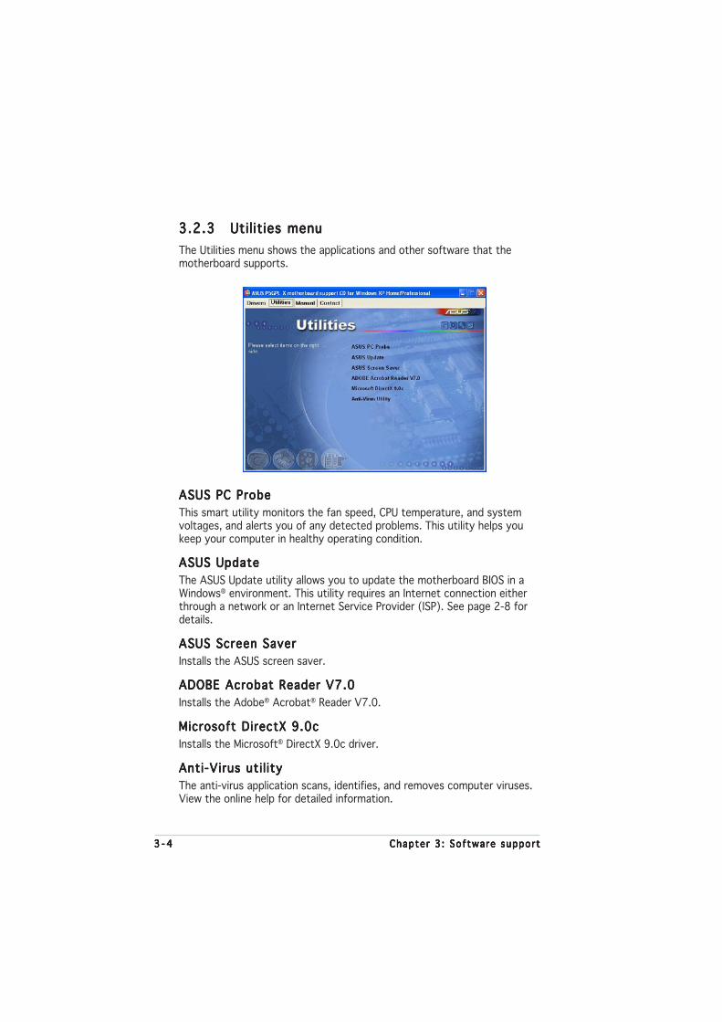
3 - 43 - 43 - 43 - 43 - 4 Chapter 3 : Software supportChapter 3 : Software supportChapter 3 : Software supportChapter 3 : Software supportChapter 3 : Software support
3.2.33.2.33.2.33.2.33.2.3 Utilities menuUtilities menuUtilities menuUtilities menuUtilities menu
The Utilities menu shows the applications and other software that themotherboard supports.
ASUS PC ProbeASUS PC ProbeASUS PC ProbeASUS PC ProbeASUS PC Probe
This smart utility monitors the fan speed, CPU temperature, and systemvoltages, and alerts you of any detected problems. This utility helps youkeep your computer in healthy operating condition.
ASUS UpdateASUS UpdateASUS UpdateASUS UpdateASUS Update
The ASUS Update utility allows you to update the motherboard BIOS in aWindows® environment. This utility requires an Internet connection eitherthrough a network or an Internet Service Provider (ISP). See page 2-8 fordetails.
ASUS Screen SaverASUS Screen SaverASUS Screen SaverASUS Screen SaverASUS Screen Saver
Installs the ASUS screen saver.
ADOBE Acrobat Reader V7.0ADOBE Acrobat Reader V7.0ADOBE Acrobat Reader V7.0ADOBE Acrobat Reader V7.0ADOBE Acrobat Reader V7.0
Installs the Adobe® Acrobat® Reader V7.0.
Microsoft DirectX 9.0cMicrosoft DirectX 9.0cMicrosoft DirectX 9.0cMicrosoft DirectX 9.0cMicrosoft DirectX 9.0c
Installs the Microsoft® DirectX 9.0c driver.
Anti-Virus uti l ityAnti-Virus uti l ityAnti-Virus uti l ityAnti-Virus uti l ityAnti-Virus uti l ity
The anti-virus application scans, identifies, and removes computer viruses.View the online help for detailed information.

ASUS P5GPL-XASUS P5GPL-XASUS P5GPL-XASUS P5GPL-XASUS P5GPL-X 3 - 53 - 53 - 53 - 53 - 5
3.2.43.2.43.2.43.2.43.2.4 ASUS Contact informationASUS Contact informationASUS Contact informationASUS Contact informationASUS Contact information
Click the Contact Contact Contact Contact Contact tab to display the ASUS contact information. You canalso find this information on the inside front cover of this user guide.

3 - 63 - 63 - 63 - 63 - 6 Chapter 3 : Software supportChapter 3 : Software supportChapter 3 : Software supportChapter 3 : Software supportChapter 3 : Software support

ASUS P5GPL-XASUS P5GPL-XASUS P5GPL-XASUS P5GPL-XASUS P5GPL-X
ACPU features
The Appendix describes the CPUfeatures that the motherboardsupports.
A - 2A - 2A - 2A - 2A - 2 Append ix : CPU featuresAppend ix : CPU featuresAppend ix : CPU featuresAppend ix : CPU featuresAppend ix : CPU features
A.1 Intel® EM64T
• The motherboard is fully compatible with Intel® Pentium® 4 LGA775processors running on 32-bit operating systems.
• The motherboard comes with a BIOS file that supports EM64T. Youcan download the latest BIOS file from the ASUS website(www.asus.com/support/download/) if you need to update the BIOSfile. See Chapter 2 for details.
• Visit www.intel.com for more information on the EM64T feature.
• Visit www.microsoft.com for more information on Windows® 64-bit OS.
Using the IntelUsing the IntelUsing the IntelUsing the IntelUsing the Intel®®®®® EM64T feature EM64T feature EM64T feature EM64T feature EM64T feature
To use the Intel® EM64T feature:
1. Install an Intel® Pentium® 4 CPU that supports the Intel® EM64T.
2. Install a 64-bit operating system (Windows® XP Professional x64Edition or Windows® Server 2003 x64 Edition).
3. Install the 64-bit drivers for the motherboard components and devicesfrom the support CD.
4. Install the 64-bit drivers for expansion cards or add-on devices, if any.
Refer to the expansion card or add-on device(s) documentation, or visitthe related website, to verify if the card/device supports a 64-bit system.
A.2 Enhanced Intel SpeedStep®
Technology (EIST)
• The motherboard comes with a BIOS file that supports EIST. You candownload the latest BIOS file from the ASUS website(www.asus.com/support/download/) if you need to update theBIOS. See Chapter 2 for details.
• Visit www.intel.com for more information on the EIST feature.
A.2.1A.2.1A.2.1A.2.1A.2.1 System requirementsSystem requirementsSystem requirementsSystem requirementsSystem requirements
Before using EIST, check your system if it meets the followingrequirements:
• Intel® Pentium® 4 processor with EIST support
• BIOS file with EIST support
• Operating system with EIST support (Windows® XP SP2/Windows®
Server 2003 SP1/Linux 2.6 kernel or later versions)
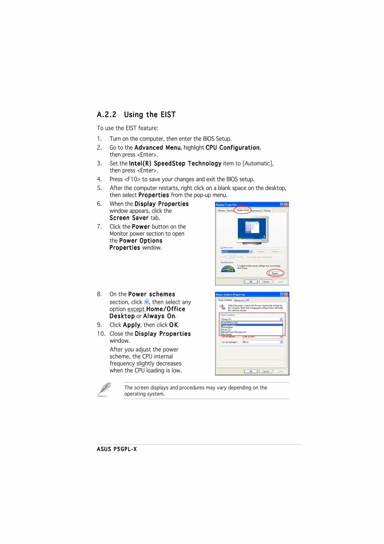
ASUS P5GPL-XASUS P5GPL-XASUS P5GPL-XASUS P5GPL-XASUS P5GPL-X
A.2.2A.2.2A.2.2A.2.2A.2.2 Using the EISTUsing the EISTUsing the EISTUsing the EISTUsing the EIST
To use the EIST feature:
1. Turn on the computer, then enter the BIOS Setup.
2. Go to the Advanced MenuAdvanced MenuAdvanced MenuAdvanced MenuAdvanced Menu, highlight CPU ConfigurationCPU ConfigurationCPU ConfigurationCPU ConfigurationCPU Configuration,then press <Enter>.
3. Set the Intel(R) SpeedStep TechnologyIntel(R) SpeedStep TechnologyIntel(R) SpeedStep TechnologyIntel(R) SpeedStep TechnologyIntel(R) SpeedStep Technology item to [Automatic],then press <Enter>.
4. Press <F10> to save your changes and exit the BIOS setup.
5. After the computer restarts, right click on a blank space on the desktop,then select Properties Properties Properties Properties Properties from the pop-up menu.
6. When the Display PropertiesDisplay PropertiesDisplay PropertiesDisplay PropertiesDisplay Propertieswindow appears, click theScreen Saver Screen Saver Screen Saver Screen Saver Screen Saver tab.
7. Click the Power Power Power Power Power button on theMonitor power section to openthe Power OptionsPower OptionsPower OptionsPower OptionsPower OptionsProperties Properties Properties Properties Properties window.
8. On the Power schemesPower schemesPower schemesPower schemesPower schemes
section, click , then select anyoption except Home/Off iceHome/Off iceHome/Off iceHome/Off iceHome/Off iceDesktopDesktopDesktopDesktopDesktop or A lways OnAlways OnAlways OnAlways OnAlways On.
9. Click App lyApp lyApp lyApp lyApp ly, then click O KO KO KO KO K.
10. Close the Disp lay Propert iesDisp lay Propert iesDisp lay Propert iesDisp lay Propert iesDisp lay Propert ieswindow.
After you adjust the powerscheme, the CPU internalfrequency slightly decreaseswhen the CPU loading is low.
The screen displays and procedures may vary depending on theoperating system.

A - 4A - 4A - 4A - 4A - 4 Append ix : CPU featuresAppend ix : CPU featuresAppend ix : CPU featuresAppend ix : CPU featuresAppend ix : CPU features
A.3 Intel® Hyper-Threading Technology
• The motherboard supports Intel® Pentium® 4 LGA775 processorswith Hyper-Threading Technology.
• Hyper-Threading Technology is supported under Windows® XP/2003Server and Linux 2.4.x (kernel) and later versions only. Under Linux, usethe Hyper-Threading compiler to compile the code. If you are using anyother operating systems, disable the Hyper-Threading Techonologyitem in the BIOS to ensure system stability and performance.
• Installing Windows® XP Service Pack 1 or later version is recommended.
• Make sure to enable the Hyper-Threading Technology item in BIOSbefore installing a supported operating system.
• For more information on Hyper-Threading Technology, visitwww.intel.com/info/hyperthreading.
Using the Hyper-Threading TechnologyUsing the Hyper-Threading TechnologyUsing the Hyper-Threading TechnologyUsing the Hyper-Threading TechnologyUsing the Hyper-Threading Technology
To use the Hyper-Threading Technology:
1. Install an Intel® Pentium® 4 CPU that supports Hyper-ThreadingTechnology.
2. Power up the system and enter the BIOS Setup. Under the AdvancedAdvancedAdvancedAdvancedAdvancedMenuMenuMenuMenuMenu, make sure that the item Hyper-Threading Technology Hyper-Threading Technology Hyper-Threading Technology Hyper-Threading Technology Hyper-Threading Technology isset to Enab ledEnab ledEnab ledEnab ledEnab led.
The BIOS item appears only if you installed a CPU that supportsHyper-Threading Technology.
3. Restart the computer.