Embed Size (px)
Citation preview

Mot
herb
oard
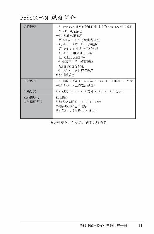
P5S800-VM

2
C1832
© 2004

3

4

5

6

7
•
•
•
•
•
•
•
•
•
•
•
•

8
•
•
•

9
™
Jumper Free(Default)
2 3
Jumper Mode
1 2

10
®
®
®
®
®
11

12


1-2
® ®
®
®

1-3
®
®
®

1-4
1-5
P5S
800-V
M®
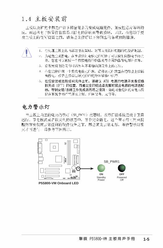
P5S800-VM Onboard LED
SB_PWR1
ONStandbyPower
OFFPowered
Off
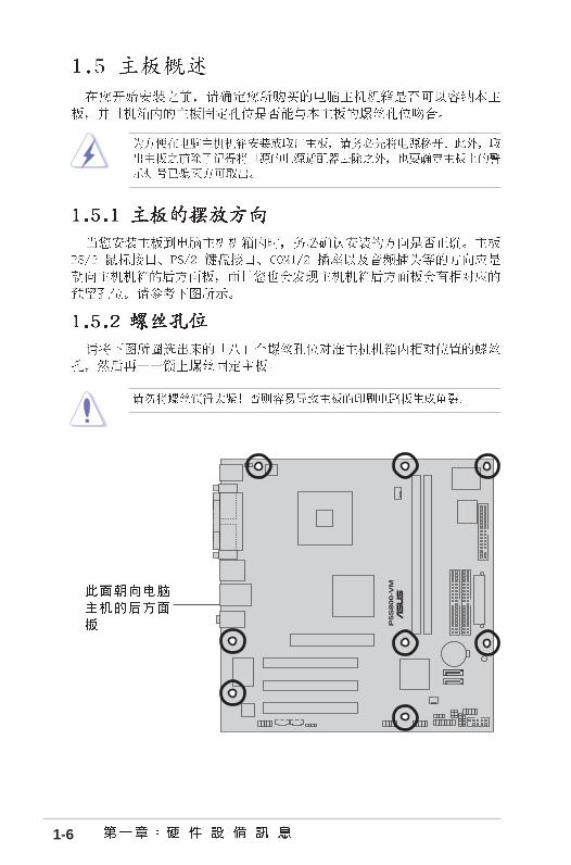
1-6
P5S
800-V
M®

1-7
P5S
800-V
M
CD1
ATX12V1
KBPWR1
SB_PWR1
GAME1
USB78USB56
CPU_FAN1
SATA1
LGA775
®
COM2
CHA_FAN1
SATA2
COM1
VGA1
F_PANEL
AUX1SPDIF1FP_AUDIO
IR_C
ON
1
SPEAKER1
PLE
D1
CLR
TC
1
CHASSIS1

1-8
®
• ® ®
•
•
•
P5S
800-V
M®
P5S800-VM CPU Socket 775

1-9
A
B

1-10
A
B
®
®
®
® ®

1-11
® ®
•
• ® ®
®
• ® ®

1-12
P5S
800-V
M®
CPU_FAN1
GNDCPU FAN PWR
CPU FAN INCPU FAN PWM
P5S800-VM CPU fan connector
A
A B
B
A
B
AB

1-13
A
A B
B
B
B
A A

1-14

1-15
P5S
800-V
M®
P5S800-VM 184-pin DDR DIMM socketsD
IMM
1
DIM
M2

1-16
• •
• •
• •
• •
• •
• •
• •
• •
• •
• •
• •
• •
• •
• •
• •
• •
• •
• •
• •
• •
• •
• •
• •
• •
• •
• •
• •
• •
• •
• •
• •
• •
• •
• •
• •
• •
• •
• •

1-17
3
1
2
1
1
2
1
2
1
1

1-18

1-19

1-20
P5S
800-V
M®
P5S800-VM Accelerated Graphics Port (AGP)
Keyed for 1.5v

1-21
P5S
800-V
M®
P5S800-VM Clear RTC RAM
CLRTC1
NormalClear CMOS(Default)
12 2
3

1-22
1
11 7
2 3
10
4
5
6
9 8
P5S
800-V
M®
P5S800-VM Keyboard power setting
(Default)+5V +5VSB
KBPWR1
2 31 2

1-23

1-24
•
•
P5S
800-V
M®
NOTE: Orient the red markings onthe floppy ribbon cable to PIN 1.
P5S800-VM Floppy disk drive connector
PIN 1
FLOPPY1
P5S
800-V
M®
P5S800-VM IDE connectors
NOTE: Orient the red markings(usually zigzag) on the IDEribbon cable to PIN 1.
PR
I_ID
E1
PIN 1
SE
C_I
DE
1

1-25
•
•
P5S
800-V
M®
P5S800-VM SATA connectors
SATA2
SATA1
GN
DR
SAT
A_T
XP
1R
SAT
A_T
XN
1G
ND
RS
ATA
_RX
P1
RS
ATA
_RX
N1
GN
D
GN
DR
SAT
A_T
XP
2R
SAT
A_T
XN
2G
ND
RS
ATA
_RX
P2
RS
ATA
_RX
N2
GN
D
P5S
800-V
M®
P5S800-VM Speaker out connector
SPEAKER1
+5V
1
GND
Speak OutGND

1-26
P5S
800-V
M®
P5S800-VM Fan connectors
CPU_FAN1
GNDCPU FAN PWR
CPU FAN INCPU FAN PWM
CHA_FAN1
GN
D
Rot
atio
n+
12V
P5S
800-V
M®
P5S800-VM Digital audio connector
+5V
SP
DIF
OU
TG
ND
SPDIF1

1-27
•
•
•
P5S
800-V
M®
P5S800-VM ATX power connectors
ATXPWR1
ATX12V1
+3.3VDC-12.0VDCCOMPS_ON#
COMCOM
COM-5.0VDC+5.0VDC+5.0VDC
PWR_OK
+12.0VDC
+3.3VDC+3.3VDC
COM
+5.0VDCCOM
+5.0VDC
COM
+5VSB
+12V DC GND
+12V DC GND
P5S
800-V
M®
P5S800-VM PLED connector
PLED1
PLED+1
NCPLED-

1-28
P5S
800-V
M®
P5S800-VM Internal audio connectors
AUX1 (White) CD1 (Black)
Rig
ht A
udio
Cha
nnel
Left
Aud
io C
hann
el
Gro
und
Rig
ht A
udio
Cha
nnel
Left
Aud
io C
hann
el
Gro
und
P5S
800-V
M®
P5S800-VM USB 2.0 connectors
USB56
US
B+
5VU
SB
_P6-
US
B_P
6+G
ND
NC
US
B+
5VU
SB
_P5-
US
B_P
5+G
ND
1USB78
US
B+
5VU
SB
_P8-
US
B_P
8+G
ND
NC
US
B+
5VU
SB
_P7-
US
B_P
7+G
ND
1

1-29
P5S
800-V
M®
P5S800-VM Front panel audio connector
FP_AUDIO1
BLI
NE
_OU
T_L
MIC
2
Line
out
_R
Line
out
_L
BLI
NE
_OU
T_R
NC
MIC
PW
R+
5VA
AG
ND
P5S
800-V
M®
P5S800-VM Serial port connector
PIN 1
COM2
P5S
800-V
M®
P5S800-VM System panel connector
F_PANEL1
PLE
D-
PW
R
PLE
D+
Gro
und
GN
DR
eset
HD
LED
+H
DLE
D-
HDLED RESET
PLED PWRBTN*

1-30
P5S
800-V
M®
P5S800-VM Chassis intrusion connector
CHASSIS1
+5V
SB
_MB
Cha
ssis
Sig
nal
GN
D
(Default)

2-1

2-2

2-3
•
•
EZFlash starting BIOS update
Checking for floppy...
EZFlash starting BIOS update
Checking for floppy...
Floppy found!
Reading file “P5S800VM.rom”. Completed.
Start erasing.......|
Start programming...|
Flashed successfully. Rebooting.

2-4
A:\>afudos /oOLDBIOS1.ROM
AMI Firmware Update Utility - Version 1.10
Copyright (C) 2002 American Megatrends, Inc. All rightsreserved.
Reading flash ..... done
Write to file ...ok
A:\>
•
•
A:\>afudos /oOLDBIOS1.ROM

2-5
A:\>afudos /iP5S800VM.ROM
A:\>afudos /iP5S800VM.ROM
AMI Firmware Update Utility - Version 1.19(ASUS V2.07(03.11.24BB))
Copyright (C) 2003 American Megatrends, Inc. All rights reserved.
Reading file ..... done
Erasing flash .... done
Writing flash .... 0x0008CC00 (9%)
A:\>afudos /iP5S800VM.ROM
AMI Firmware Update Utility - Version 1.19(ASUS V2.07(03.11.24BB))
Copyright (C) 2003 American Megatrends, Inc. All rights reserved.
Reading file ...... done
Erasing flash ..... done
Writing flash ..... 0X0008CC00 (9%)
Verifying flash ... done
A:\>

2-6
Bad BIOS checksum. Starting BIOS recovery...
Checking for floppy...
Bad BIOS checksum. Starting BIOS recovery...
Checking for floppy...
Floppy found!
Reading file “P5S800VM.ROM”. Completed.
Start flashing...

2-7
Bad BIOS checksum. Starting BIOS recovery...
Checking for floppy...
Floppy not found!
Checking for CD-ROM...
CD-ROM found!
Reading file “P5S800VM.ROM”. Completed.
Start flashing...
Bad BIOS checksum. Starting BIOS recovery...
Checking for floppy...

2-8

2-9

2-10

2-11

2-12
System Time [11:51:19]System Date [Thu 10/07/2004]Legacy Diskette A [1.44M, 3.5 in]
Primary IDE Master :[ST320413A]Primary IDE Slave :[ASUS CD-S360]Secondary IDE Master :[Not Detected]Secondary IDE Slave :[Not Detected]
OnChip SATA Controller [Enabled]System Information
Use [ENTER], [TAB]or [SHIFT-TAB] toselect a field.
Use [+] or [-] toconfigure system time.

2-13
System Time [11:10:19]System Date [Thu 03/27/2003]Legacy Diskette A [1.44M, 3.5 in]Language [English]
Primary IDE Master :[ST320413A] Primary IDE Slave :[ASUS CD-S340] Secondary IDE Master :[Not Detected] Secondary IDE Slave :[Not Detected] Third IDE Master :[Not Detected] Fourth IDE Master :[Not Detected] IDE Configuration
System Information
Use [ENTER], [TAB]or [SHIFT-TAB] toselect a field.
Use [+] or [-] toconfigure system time.
Select Screen Select Item+- Change FieldTab Select FieldF1 General HelpF10 Save and ExitESC Exit
Select Screen Select Item+- Change OptionF1 General HelpF10 Save and ExitESC Exit
Advanced Chipset settings
WARNING: Setting wrong values in the sections below may cause system to malfunction.
Configure DRAM Timing by SPD [Enabled]Memory Acceleration Mode [Auto]DRAM Idle Timer [Auto]DRAm Refresh Rate [Auto]
Graphic Adapter Priority [AGP/PCI]Graphics Aperture Size [ 64 MB]Spread Spectrum [Enabled]
ICH Delayed Transaction [Enabled]
MPS Revision [1.4]

2-14
System Time [11:51:19]System Date [Thu 10/07/2004]Legacy Diskette A [1.44M, 3.5 in]Language [English]
Primary IDE Master :[ST320413A]Primary IDE Slave :[ASUS CD-S360]Secondary IDE Master :[Not Detected]Secondary IDE Slave :[Not Detected]
OnChip SATA Controller [Enabled]System Information
2-15
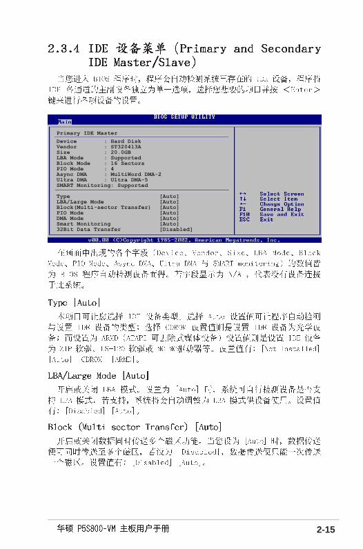
Primary IDE Master
Device : Hard DiskVendor : ST320413ASize : 20.0GBLBA Mode : SupportedBlock Mode : 16 SectorsPIO Mode : 4Async DMA : MultiWord DMA-2Ultra DMA : Ultra DMA-5SMART Monitoring: Supported
Type [Auto]LBA/Large Mode [Auto]Block(Multi-sector Transfer) [Auto]PIO Mode [Auto]DMA Mode [Auto]Smart Monitoring [Auto]32Bit Data Transfer [Disabled]

2-16
AMIBIOS
Version : 08.00.10
Build Date : 10/07/04
Processor
Type : Genuine Intel(R) CPU 3.20GHz
Speed : 2800 MHz
Count : 1
System Memory
Size : 512MB

2-17
Configure System Frequency/Voltage
AI Overclocking [Standard]Spread Spectrum [Enabled]DRAM Frequency [Auto]CPU Vcore Offset +0.1V [Disabled]AGP VDDQ Voltage [Auto]DDR Reference Voltage [Auto]
Select the target CPUfrequency, and therelevant parameterswill be auto-adjusted.Frequencies higherthan CPU manufacturerrecommends are notguaranteed to bestable. If the systembecomes unstable,return to the default.
Configure CPU.
Select Screen Select ItemEnter Go to Sub-screenF1 General HelpF10 Save and ExitESC Exit
JumperFree ConfigurationCPU ConfigurationChipsetOnboard Devices ConfigurationPCI PnPUSB ConfigurationInstant Music Configuration

2-18
2-19
Select Screen Select Item+- Change OptionF1 General HelpF10 Save and ExitESC Exit
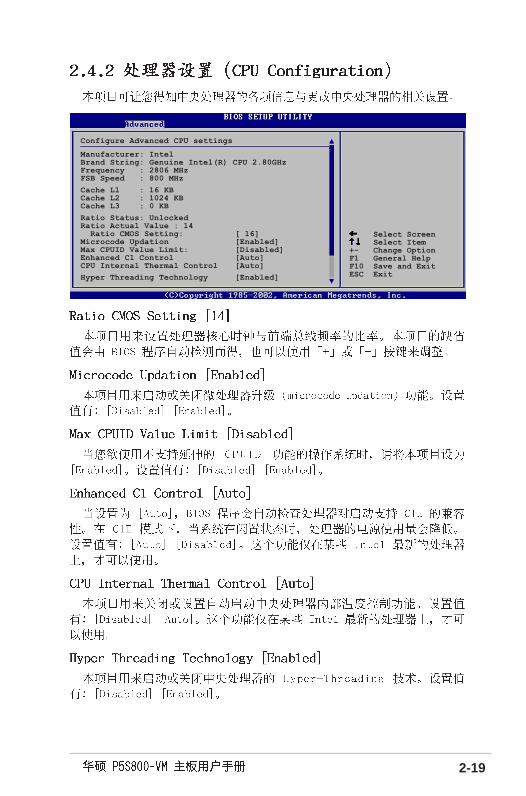
Configure Advanced CPU settings
Manufacturer: IntelBrand String: Genuine Intel(R) CPU 2.80GHzFrequency : 2806 MHzFSB Speed : 800 MHz
Cache L1 : 16 KBCache L2 : 1024 KBCache L3 : 0 KB
Ratio Status: UnlockedRatio Actual Value : 14 Ratio CMOS Setting: [ 16]Microcode Updation [Enabled]Max CPUID Value Limit: [Disabled]Enhanced C1 Control [Auto]CPU Internal Thermal Control [Auto]
Hyper Threading Technology [Enabled]

2-20
NorthBridge SiS661FX ConfigurationSouthBridge SiS964 Configuration
Primary Graphics Adapter [PCI]MA 1T/2T Select [Auto]DRAM CAS# Latency [By SPD]DRAM Precharge Delay [Auto]DRAM RAS# to CAS# Delay [Auto]DRAM RAS# Precharge [Auto]Graphic Win Size [ 64MB]AGP Fast Write Control [Disabled]
Share Memory Size [ 32MB]

2-21
Onboard AC97 Device [Enabled]
Select Screen
Configure Win637 Super IO Chipset
Serial Port1 Address [3F8/IRQ4]Serial Port2 Address [2F8/IRQ3]Parallel Port Address [378]Parallel Port Mode [Normal]ECP Mode DMA Channel [DMA3]Parallel Port IRQ [IRQ7]Onboard Game/MIDI Port [Disabled]
Onboard RTL8100C LAN DEVICE [Enabled]Onboard LAN Boot ROM [Disabled]

2-22

2-23
Select Screen Select Item+- Change OptionF1 General HelpF10 Save and ExitESC Exit
Advanced PCI/PnP Settings
WARNING: Setting wrong values in below sections may cause system to malfunction.
Plug And Play O/S [No]PCI Latency Timer [64]Allocate IRQ to PCI VGA [Yes]Palette Snooping [Disabled]PCI IDE BusMaster [Enabled]
IRQ3 [PCI Device]IRQ4 [PCI Device]IRQ5 [PCI Device]IRQ7 [PCI Device]IRQ9 [PCI Device]IRQ10 [PCI Device]IRQ11 [PCI Device]IRQ14 [PCI Device]IRQ15 [PCI Device]

2-24
Select Screen
Enables USB hostcontrollers.
Onboard SiS USB1.1 DEVICE [Enabled]Onboard SiS USB2.0 DEVICE [Enabled]
USB Devices Enabled: NoneModule Version - 2.23.2-9.4
USB Device Enabled : None
Legacy USB Support [Auto]USB 2.0 Controller Mode [Enabled]Stop EHCT HC in OHCT handover [Enabled]

2-25
Instant Music Option
Instant Music [Enabled]
2-26
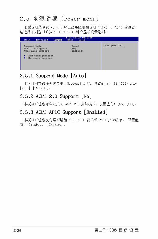
Configure CPU.Suspend Mode [Auto]ACPI 2.0 Support [No]ACPI APIC Support [Enabled]
APM ConfigurationHardware Monitor

2-27
Enabled or disableAPM.
Power Button Mode [On/Off]
Restore on AC Power Loss [Always OFF]Power On By PS/2 Keyboard [Disabled]Power On By PS/2 Mouse [Disabled]Power On By PCI Devices [Disabled]Power On By External Modems [Disabled]Power On By RTC Alarm [Disabled]

2-28
Select Screen Select Item+- Change OptionF1 General Help
Hardware Monitor
CPU Temperature [51ºC/122.5ºF]MB Temperature [41ºC/105.5ºF]
CPU Fan Speed [3813 RPM]Chassis Fan Speed [N/A]Power Fan Speed [N/A]
VCORE Voltage [ 1.320V]3.3V Voltage [ 3.345V]5V Voltage [ 5.094V]12V Voltage [11.880V]

2-29

2-30
APM Configuration
Boot Device Priority
Boot Settings ConfigurationSecurity
Boot Device Priority
1st Boot Device [1st FLOPPY DRIVE]2nd Boot Device [PM-ST330620A]3rd Boot Device [PS-ASUS CD-S360]
Hard Disk Devices
1st Device [PM-IBM-DJNA-371350]2nd Device [Maxtor 6B200M0]

2-31
Boot Settings Configuration
Quick Boot [Enabled]Full Screen Logo [Enabled]AddOn ROM Display Mode [Force BIOS]Bootup Num-Lock [On]PS/2 Mouse Support [Auto]Wait For ‘F1’ If Error [Enabled]Hit ‘DEL’ Message Display [Enabled]Interrupt 19 Capture [Disabled]
Allows BIOS to skipcertain tests whilebooting. This willdecrease the timeneeded to boot thesystem.

2-32
Security Settings
Supervisor Password : Not InstalledUser Password : Not Installed
Change Supervisor Password
Boot Sector Virus Protection [Disabled]
<Enter> to changepassword.<Enter> again todisabled password.

2-33
Select ScreenSelect Item
Security Settings
Supervisor Password : Not InstalledUser Password : Not Installed
Change Supervisor PasswordUser Access Level [Full Access]Change User PasswordClear User PasswordPassword Check [Setup]
Boot Sector Virus Protection [Disabled]

2-34
Exit system setupafter saving thechanges.
F10 key can be usedfor this operation.
Select Screen Select ItemEnter Go to Sub-screenF1 General HelpF10 Save and ExitESC Exit
Exit Options
Exit & Save ChangesExit & Discard ChangesDiscard Changes
Load Setup Defaults

2-35

2-36


3-2

3-3

3-4

3-5

3-6