Embed Size (px)
Citation preview

P1: SYV/SPH P2: SYV/UKS QC: SYV/UKS T1: SYV
CB268-FM April 26, 2002 17:42 Char Count= 0
Principles of HelicopterAerodynamics
J. GORDON LEISHMANUniversity of Maryland

P1: SYV/SPH P2: SYV/UKS QC: SYV/UKS T1: SYV
CB268-FM April 26, 2002 17:42 Char Count= 0
TO MY STUDENTSin appreciation of all they have taught me
PUBLISHED BY THE PRESS SYNDICATE OF THE UNIVERSITY OF CAMBRIDGE
The Pitt Building, Trumpington Street, Cambridge, United Kingdom
CAMBRIDGE UNIVERSITY PRESS
The Edinburgh Building, Cambridge CB2 2RU, UK40 West 20th Street, New York, NY 10011-4211, USA10 Stamford Road, Oakleigh,VIC 3166, AustraliaRuiz de Alarcon 13, 28014 Madrid, SpainDock House, The Waterfront, Cape Town 8001, South Africa
http://www.cambridge.org
C© Cambridge University Press 2000
This book is in copyright. Subject to statutory exceptionand to the provisions of relevant collective licensing agreements,no reproduction of any part may take place withoutthe written permission of Cambridge University Press.
First published 2000Reprinted with corrections 2001
Printed in the United States of America
TypefaceTimes Roman 10/12 pt. SystemLATEX 2ε [TB]
A catalog record for this book is available from the British Library.
Library of Congress Cataloging in Publication Data
Leishman, J. Gordon.Principles of helicopter aerodynamics / J. Gordon Leishman.
p. cm.Includes bibliographical references (p. ).
ISBN 0-521-66060-2 (hardcover)
1. Helicopters– Aerodynamics.TL716.L43 2000629.133′352– dc21 99-38291
CIP
ISBN 0 521 66060 2 hardback

P1: SYV/SPH P2: SYV/UKS QC: SYV/UKS T1: SYV
CB268-FM April 26, 2002 17:42 Char Count= 0
Contents
List of Figures pagexivList of Tables xxviPreface xxviiAcknowledgments xxxiList of Main Symbols xxxiii
1 Introduction: A History of Helicopter Flight 1
1.1 Introduction 11.2 Early Attempts at Vertical Flight 21.3 The Era of the Autogiro 121.4 The First Successes with Helicopters 141.5 Maturing Technology 221.6 Tilt-Wings and Tilt-Rotors 271.7 Chapter Review 281.8 Questions 29Bibliography 30
2 Fundamentals of Rotor Aerodynamics 33
2.1 Introduction 332.2 Momentum Theory 362.2.1 Flow near a Hovering Rotor 372.2.2 Conservation Laws of Fluid Mechanics 382.2.3 Application to a Hovering Rotor 392.2.4 Disk Loading and Power Loading 422.2.5 Induced Inflow Ratio 432.2.6 Thrust and Power Coefficients 432.2.7 Nonideal Effects on Rotor Performance 442.2.8 Figure of Merit 462.2.9 Worked Example 472.2.10 Induced Tip Loss 482.2.11 Rotor Solidity and Blade Loading Coefficient 502.2.12 Power Loading 522.3 Axial Climb and Descent 532.3.1 Axial Climb 532.3.2 Axial Descent 552.3.3 The Region−2 ≤ Vc/vh ≤ 0 572.3.4 Power Required 592.3.5 Working States of the Rotor in Axial Flight 602.3.6 Autorotation 60
vii

P1: SYV/SPH P2: SYV/UKS QC: SYV/UKS T1: SYV
CB268-FM April 26, 2002 17:42 Char Count= 0
viii Contents
2.4 Momentum Analysis in Forward Flight 632.4.1 Induced Velocity in Forward Flight 642.4.2 Special Case,α = 0 652.4.3 Numerical Solution to Inflow Equation 662.4.4 Validity of the Inflow Equation 672.4.5 Rotor Power in Forward Flight 682.4.6 Other Applications of the Momentum Theory 692.5 Chapter Review 732.6 Questions 73Bibliography 76
3 Blade Element Analysis 78
3.1 Introduction 783.2 Blade Element Analysis in Hover and Axial Flight 803.2.1 Integrated Rotor Thrust and Power 823.2.2 Thrust Approximations 823.2.3 Untwisted Blades, Uniform Inflow 833.2.4 Linearly Twisted Blades, Uniform Inflow 843.2.5 Torque/Power Approximations 843.2.6 Tip-Loss Factor 853.3 Blade Element Momentum Theory (BEMT) 873.3.1 Ideal Twist 913.3.2 BEMT– A Numerical Approach 923.3.3 Distributions of Inflow and Airloads 933.3.4 The Optimum Hovering Rotor 963.3.5 Circulation Theory of Lift 993.3.6 Power Estimates 1003.3.7 Prandtl’s Tip-Loss Function 1023.3.8 Figure of Merit 1053.3.9 Further Comparisons of BEMT with Experiment 1063.3.10 Compressibility Corrections 1073.3.11 Equivalent Chords and Weighted Solidity 1103.3.12 Mean Wing Chords 1103.3.13 Thrust Weighted Solidity 1113.3.14 Power/Torque Weighted Solidity 1113.3.15 Weighted Solidity of the Optimum Rotor 1123.3.16 Weighted Solidities of Tapered Blades 1123.3.17 Mean Lift Coefficient 1133.4 Blade Element Analysis in Forward Flight 1133.4.1 Blade Forces 1143.4.2 Induced Velocity Field 1153.5 Chapter Review 1233.6 Questions 124Bibliography 126
4 Rotating Blade Motion 128
4.1 Introduction 1284.2 Types of Rotors 1294.3 Equilibrium about the Flapping Hinge 131

P1: SYV/SPH P2: SYV/UKS QC: SYV/UKS T1: SYV
CB268-FM April 26, 2002 17:42 Char Count= 0
Contents ix
4.4 Equilibrium about the Lead/Lag Hinge 1334.5 Equation of Motion for Flapping Blade 1344.6 Physical Description of Blade Flapping 1394.6.1 Coning Angle 1394.6.2 Longitudinal Flapping 1394.6.3 Lateral Flapping 1404.7 Dynamics of Blade Flapping with a Hinge Offset 1414.8 Blade Feathering and the Swashplate 1424.9 Review of Rotor Reference Axes 1444.10 Dynamics of a Lagging Blade with Hinge Offset 1474.11 Coupled Flap–Lag Motion 1494.12 Introduction to Rotor Trim 1504.13 Chapter Review 1554.14 Questions 156Bibliography 157
5 Basic Helicopter Performance 159
5.1 Introduction 1595.2 Hovering and Axial Climb Performance 1595.3 Forward Flight Performance 1635.3.1 Induced Power 1645.3.2 Blade Profile Power 1645.3.3 Parasitic Power 1665.3.4 Climb Power 1665.3.5 Tail Rotor Power 1665.3.6 Total Power 1675.3.7 Effect of Gross Weight 1685.3.8 Effect of Density Altitude 1695.3.9 Lift-to-Drag Ratios 1695.3.10 Climb Performance 1705.3.11 Speed for Minimum Power 1715.3.12 Speed for Maximum Range 1735.3.13 Range–Payload and Endurance–Payload 1745.3.14 Factors Affecting Maximum Attainable Forward Speed 1745.3.15 Performance of Coaxials and Tandems 1765.4 Autorotation Revisited 1785.4.1 Autorotation in Forward Flight 1805.4.2 Height–Velocity (HV) Curve 1825.4.3 Autorotation Index 1845.5 Ground Effect 1855.6 Chapter Review 1895.7 Questions 190Bibliography 191
6 Conceptual Design of Helicopters 193
6.1 Introduction 1936.2 Design Requirements 1936.3 Design of the Main Rotor 194

P1: SYV/SPH P2: SYV/UKS QC: SYV/UKS T1: SYV
CB268-FM April 26, 2002 17:42 Char Count= 0
x Contents
6.3.1 Rotor Diameter 1956.3.2 Tip Speed 1976.3.3 Rotor Solidity 1996.3.4 Number of Blades 2016.3.5 Blade Twist 2036.3.6 Blade Planform and Tip Shape 2046.3.7 Airfoil Sections 2086.3.8 The BERP Rotor 2096.4 Fuselage Design 2126.4.1 Fuselage Drag 2136.4.2 Vertical Drag or Download 2186.4.3 Fuselage Side-Force 2196.5 Empennage Design 2196.5.1 Horizontal Stabilizer 2206.5.2 Vertical Stabilizer 2226.5.3 Modeling 2226.6 Design of Tail Rotors 2226.6.1 Physical Size 2236.6.2 Thrust Requirements 2246.6.3 Pushers Versus Tractors 2256.6.4 Design Requirements 2266.6.5 Aerodynamic Interactions 2266.6.6 Typical Tail Rotor Designs 2276.6.7 Other Antitorque Devices 2396.7 High Speed Rotorcraft 2326.7.1 Compound Helicopters 2326.7.2 Tilt-Rotors 2336.7.3 Other High Speed Rotorcraft 2346.8 Chapter Review 2356.9 Questions 236Bibliography 237
7 Rotor Airfoil Aerodynamics 243
7.1 Introduction 2437.2 Rotor Airfoil Requirements 2447.3 Reynolds Number and Mach Number 2457.3.1 Reynolds Number 2467.3.2 Concept of the Boundary Layer 2477.3.3 Mach Number 2517.4 Airfoil Shape Definition 2537.5 Airfoil Pressure Distributions 2567.5.1 Pressure Coefficient 2567.5.2 Synthesis of Chordwise Pressure 2577.5.3 Measurements of Chordwise Pressure 2587.6 Aerodynamics of a Typical Airfoil Section 2607.6.1 Integration of Distributed Forces 2607.6.2 Pressure Integration 2627.6.3 Typical Force and Moment Results 2647.7 Pitching Moment 264
P1: SYV/SPH P2: SYV/UKS QC: SYV/UKS T1: SYV
CB268-FM April 26, 2002 17:42 Char Count= 0
Contents xi
7.7.1 Aerodynamic Center 2677.7.2 Center of Pressure 2687.7.3 Effect of Airfoil Shape on Moments 2697.7.4 Use of Tabs 2727.8 Maximum Lift and Stall Characteristics 2747.8.1 Effects of Reynolds Number 2767.8.2 Effects of Mach Number 2797.9 Advanced Rotor Airfoil Design 2857.10 Representing Static Airfoil Characteristics 2887.10.1 Linear Aerodynamics 2887.10.2 Nonlinear Aerodynamics 2897.10.3 Table Look-Up 2897.10.4 Direct Curve Fitting 2907.10.5 Beddoes Method 2917.10.6 High Angle of Attack Range 2937.11 Chapter Review 2957.12 Questions 296Bibliography 298
8 Unsteady Aerodynamics 302
8.1 Introduction 3028.2 Sources of Unsteady Aerodynamic Loading 3038.3 Blade Wake 3038.4 Reduced Frequency and Reduced Time 3068.5 Unsteady Attached Flow 3078.6 Quasi-Steady Thin-Airfoil Theory 3088.7 Theodorsen’s Theory 3098.7.1 Pure Angle of Attack Oscillation 3138.7.2 Pure Plunging Oscillation 3158.7.3 Pitch Oscillations 3158.8 The Returning Wake: Loewy’s Problem 3188.9 The Sinusoidal Gust: Sears’s Problem 3228.10 Indicial Response: Wagner’s Problem 3238.11 The Sharp-Edged Gust: Kussner’s Problem 3268.12 Traveling Sharp-Edged Gust: Miles’s Problem 3288.13 Time-Varying Incident Velocity 3338.14 Indicial Response Method 3368.14.1 Recurrence Solution to the Duhamel Integral 3378.14.2 State-Space Solution 3408.15 Subsonic Compressible Flow 3428.15.1 Approximations to the Indicial Response 3458.15.2 Indicial Lift from Angle of Attack 3468.15.3 Indicial Lift from Pitch Rate 3488.15.4 Determination of Indicial Function Coefficients 3498.15.5 Indicial Pitching Moment from Angle of Attack 3518.15.6 Indicial Pitching Moment from Pitch Rate 3518.15.7 Unsteady Axial Force and Drag 3538.15.8 State-Space Aerodynamic Model for Compressible Flow 3558.16 Comparison with Experiment 357

P1: SYV/SPH P2: SYV/UKS QC: SYV/UKS T1: SYV
CB268-FM April 26, 2002 17:42 Char Count= 0
xii Contents
8.17 Nonuniform Vertical Velocity Field 3588.17.1 Exact Subsonic Linear Theory 3598.17.2 Approximations to the Sharp-Edged Gust Functions 3618.17.3 Response to an Arbitrary Vertical Gust 3638.17.4 Blade Vortex Interaction (BVI) Problem 3658.17.5 Convecting Vertical Gusts in Subsonic Flow 3678.18 Dynamic Inflow 3698.19 Chapter Review 3718.20 Questions 372Bibliography 374
9 Dynamic Stall 378
9.1 Introduction 3789.2 Flow Topology of Dynamic Stall 3799.3 Dynamic Stall in the Rotor Environment 3829.4 Effects of Forcing Conditions on Dynamic Stall 3839.5 Modeling of Dynamic Stall 3899.5.1 Engineering Models of Dynamic Stall 3909.5.2 Capabilities of 2-D Dynamic Stall Modeling 3939.6 Torsional Damping 3979.7 Effects of Sweep Angle on Dynamic Stall 3999.8 Effect of Airfoil Shape on Dynamic Stall 4039.9 Three-Dimensional Effects on Dynamic Stall 4059.10 Time-Varying Velocity Effects 4109.11 Prediction of In-Flight Airloads 4109.12 Chapter Review 4129.13 Questions 413Bibliography 414
10 Rotor Wakes and Tip Vortices 418
10.1 Introduction 41810.2 Flow Visualization Techniques 41810.2.1 Smoke Flow Visualization 41910.2.2 Density Gradient Methods 41910.2.3 Natural Condensation Effects 42110.3 Characteristics of the Rotor Wake in Hover 42110.4 Characteristics of the Rotor Wake in Forward Flight 42510.4.1 Wake Boundaries 42610.4.2 Blade–Vortex Interactions (BVIs) 42710.5 Other Characteristics of Rotor Wakes 43110.5.1 Periodicity 43110.5.2 Vortex Perturbations and Instabilities 43110.6 Detailed Structure of the Tip Vortices 43210.6.1 Velocity Field 43410.6.2 Models of the Vortex 43510.6.3 Vorticity Diffusion Effects and Vortex Core Growth 44010.6.4 Correlation of Rotor Tip Vortex Data 44210.7 Vortex Models of the Rotor Wake 44310.7.1 Biot–Savart Law 425
P1: SYV/SPH P2: SYV/UKS QC: SYV/UKS T1: SYV
CB268-FM April 26, 2002 17:42 Char Count= 0
Contents xiii
10.7.2 Blade Model 44610.7.3 Governing Equations for the Vortex Wake 44810.7.4 Prescribed Wake Models for Hovering Flight 45010.7.5 Prescribed Vortex Wake Models for Forward Flight 45310.7.6 Free-Vortex Wake Analyses 45810.8 Effects of Maneuvers 47010.9 Advanced Computational Models 47610.10 Interactions between the Rotor and the Airframe 47710.11 Chapter Review 47910.12 Questions 479Bibliography 481
Appendix 487
Index 489

P1: SYV/SPH P2: SYV/UKS QC: SYV/UKS T1: SYV
CB268-FM April 26, 2002 17:42 Char Count= 0
List of Figures
1.1 Time-line showing development of helicopters and autogiros prior to 1950.1.2 Leonardo da Vinci’s aerial screw machine, dated to 1483. Original drawing is MS
2173 of Manuscript (codex) B, folio 83 verso, in the collection of the Biblioth`equeL’Institut de France (Paris).
1.3 The Cornu helicopter, circa 1907. (Courtesy NASM, Smithsonian Institution, SINeg. No. 74-8533.)
1.4 Danish aviation pioneer Jens Ellehammerflew a coaxial rotor helicopter design in1914.
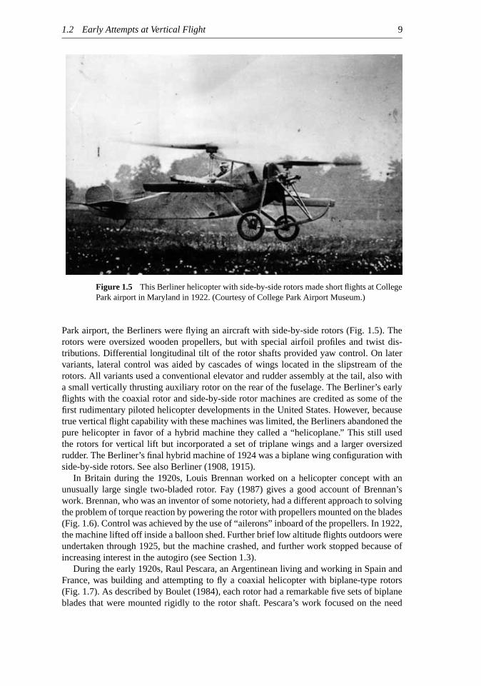
1.5 This Berliner helicopter with side-by-side rotors made shortflights at College Parkairport in Maryland in 1922. (Courtesy of College Park Airport Museum.)
1.6 The Brennan helicopter suspended in the balloon shed at RAE Farnborough, circa1922.
1.7 Pescara’s helicopter hovering in a hanger about 1923. (Courtesy NASM,Smithsonian Institution, SI Neg. No. 83-16343.)
1.8 Between 1924 and 1930, A. G. von Baumhauer made attempts tofly a singlemain rotor helicopter with a separately powered tail rotor. (Courtesy NASM,Smithsonian Institution, Neg. No. 77-721.)
1.9 Cierva’s C-19 successful two-seater autogiro, circa 1931.1.10 The Jerome–de Bothezat helicopter, which made limited controlledflights in 1922.
(Courtesy NASM, Smithsonian Institution, SI Neg. No. 87-6022.)1.11 Corradino d’Ascanio’s coaxial machine, circa 1930, which used servo-tabs on the
blades to change their lift. (Courtesy John Schneider.)1.12 The successful Breguet–Dorand coaxial helicopter, circa 1936. (Courtesy NASM,
Smithsonian Institution, SI Neg. No. A-42078-C.)1.13 The Focke Fa-61flew successfully in 1938. (Courtesy NASM, Smithsonian Insti-
tution, SI Neg. No. A-2316.)1.14 The famous Sikorsky R-4B, circa 1944.1.15 A version of the Bell-47, which was the world’s first commercially certified heli-
copter. (By permission of Bell Helicopter Textron.)1.16 The Boeing-Vertol CH-47– one of the largest and most widely used military
transport helicopters. (By permission of the Boeing Company.)1.17 A modern synchropter design, the Kaman K-Max. (By permission of Kaman Air-
craft Corporation.)1.18 The Sikorsky/Boeing RAH-66 Comanche, whichfirstflew in 1997. (By permission
of the Boeing Company.)1.19 The Bell AH-1 Huey-Cobra. (By permission of Bell Helicopter Textron.)1.20 The McDonnell–Douglas (now Boeing) AH-64 Apache. (By permission of the
Boeing Company.)1.21 A civil variant of the EH Industries EH-101. (By permission of GKN-Westland
Helicopters.)
xiv

P1: SYV/SPH P2: SYV/UKS QC: SYV/UKS T1: SYV
CB268-FM April 26, 2002 17:42 Char Count= 0
List of Figures xv
1.22 The Kamov Ka-50 helicopter, which has a coaxial rotor design. (Photo courtesyof Jari Juvonen.)
1.23 The Bell/Boeing V-22 Osprey tilt rotor. (By permission of the Boeing Company.)2.1 Distribution of incident velocity normal to the leading edge of rotor blade.
(a) Hoveringflight. (b) Forwardflight.2.2 Hovering helicopter showing the vortical rotor wake through natural condensation
of water vapor inside the tip vortex cores. (Courtesy of the US Navy, PatuxentRiver NAS.)
2.3 Schematic showing theflow structure and some aerodynamic problem areas on ahelicopter in forwardflight.
2.4 Measurements of the velocityfield near and below a hovering two-bladed rotor.Data source: Leishman et al. (1995).
2.5 Flow model used for momentum theory analysis of a rotor in axialflight.2.6 Hovering efficiency versus disk loading for a range of vertical lift aircraft.2.7 Comparison of predictions made with momentum theory to measured power for a
hovering rotor. Data source: Bagai & Leishman (1992).2.8 Figure of merit predictions made with modified momentum theory compared to
measured results for a hovering rotor. Data source: Bagai & Leishman (1992).2.9 The effect of thrust and number of blades on Prandtl’s tip loss factor.2.10 Measured and predictedfigure of merit versus thrust coefficient for a hovering
rotor with different values of solidity. Data source: Knight & Hefner (1937).2.11 Measured and predictedfigure of merit versus blade loading coefficient for a
hovering rotor with different solidities. Data source: Knight & Hefner (1937).2.12 Measured variation ofCP/CT versus thrust coefficient for a hovering rotor with
different solidities. Data source: Knight & Hefner (1937).2.13 Induced velocity variation as a function of climb and descent velocity based on
momentum theory (complete induced velocity curve).2.14 Flow model used for momentum theory analysis of a rotor in a vertical descent.2.15 Total power required as a function of climb and descent velocity (universal power
curve).2.16 The physical nature of the rotor wake in simulated axial descent. (a) Normal
working state. (b) Approaching the vortex ring state. (c) Turbulent wake state.(d) Windmill brake state. Source: University of Maryland.
2.17 Glauertflow model for momentum analysis of a rotor in forwardflight.2.18 Induced inflow ratio at the rotor diskλi /λh as a function of forward speedµ for
α = 0.2.19 Inflow ratioλ/λh as a function of forward speed ratioµ/λh for several rotor angles
of attack.2.20 Hover performance predictions for a coaxial rotor compared to measurements.
Data source: Dingeldein (1954).2.21 Tandem rotor overlap induced power correction in hover as derived from momen-
tum theory and compared to measurements. Data source: Stepniewski & Keys(1984).
3.1 Incident velocities and aerodynamic environment at a typical blade element.3.2 Variation in rotor thrust coefficient with collective pitch for rotors with different
solidities. Data source: Knight & Hefner (1937).3.3 Variation in rotor power coefficient with collective pitch for rotors with different
solidities. Data source: Knight & Hefner (1937).

P1: SYV/SPH P2: SYV/UKS QC: SYV/UKS T1: SYV
CB268-FM April 26, 2002 17:42 Char Count= 0
xvi List of Figures
3.4 Annulus of rotor disk as used for a local momentum analysis of the hovering rotor.(a) Plan view. (b) Side view.
3.5 Distribution of inflow for untwisted blade as predicted by the BEMT.3.6 Radial distribution of blade twist in ideal case.3.7 BEMT predictions of spanwise distributions of inflow and thrust on a rotor blade
for different linear twist rates. Results are compared at a constant total thrust.(a) Inflow ratio. (b) Thrust per unit span.
3.8 BEMT predictions of lift coefficient distribution on a rotor blade for different lineartwist rates. Results are compared at a constant total rotor thrust.
3.9 Representative lift-to-drag ratio of a 2-D airfoil at low angles of attack and lowMach numbers. Data source: Loftin & Smith (1949).
3.10 Radial distribution of blade chord for optimum rotor and linear approximation.3.11 Effect of blade taper on the lift coefficient distribution over a blade with constant
twist.3.12 Effect of blade twist and taper on rotorfigure of merit.3.13 Representative 2-D drag coefficient variation for an airfoil as a function of angle
of attack. Data source: Loftin & Smith (1949).3.14 Predicted power coefficient collective pitch using higher-order profile drag varia-
tion. Data source: Knight & Hefner (1937).3.15 Variation of Prandtl tip loss function versus localflow angle for a two-bladed rotor.3.16 Variation of Prandtl tip loss function versus radial position for two- and four-bladed
rotors.3.17 Spanwise variation of blade thrust using the Prandtl tip loss function.3.18 BEMT predictions of induced power factor for a four-bladed rotor with linear twist
using Prandtl’s tip loss function.3.19 Comparison of the BEMT with and without higher-order profile drag terms versus
measured thrust and power data for a four-bladed hovering rotor. Data source:Bagai & Leishman (1992).
3.20 Comparison of the BEMT with measured thrust and power data for hovering rotorsof different solidity. Data source: Knight & Hefner (1937).
3.21 Comparison of the BEMT with measured thrust and power data for a climbingrotor. (a) Thrust versus climb ratio. (b) Power versus climb ratio. Data source:Felker & McKillip (1994).
3.22 Perturbation velocities on the blade resulting from bladeflapping velocity androtor coning.
3.23 Typical variation in rotor wake skew angle with thrust and advance ratio.3.24 Variation in the longitudinal and lateral inflow across the rotor disk according to
the theory of Mangler & Squire. (a) Longitudinal inflow for Types I and III loading.(b) Lateral inflow for Types I and III loading.
3.25 Measured variations in the longitudinal and lateral time-averaged inflow acrossthe disk in forwardflight compared to inflow models. Measurements made onechord above TPP. (a) Longitudinal inflow atµ = 0.15. (b) Longitudinal inflow atµ = 0.23. (c) Longitudinal inflow atµ = 0.30. (d) Lateral inflow atµ = 0.15.(e) Lateral inflow atµ = 0.23. (f ) Lateral inflow atµ = 0.30.
4.1 Schematic showingflapping, lead/lag, and feathering motion of a rotor blade.4.2 Various types of rotor hubs. (a) Bell teetering hub design. Note the bob weights
attached to the stabilizer bar. (b) An articulated hub, in this case with coincidentflapping and lag hinges. (c) An articulated hub, with the lag hinge outboard of both

P1: SYV/SPH P2: SYV/UKS QC: SYV/UKS T1: SYV
CB268-FM April 26, 2002 17:42 Char Count= 0
List of Figures xvii
the flap and lag hinge. (d) A bearingless hub, where the mechanical hinges andbearings are replaced byflexures.
4.3 Equilibrium of blade aerodynamic and centrifugal forces about theflapping hinge.4.4 Blade with an offset lead/lag hinge.4.5 Forces acting on an element of aflapping blade.4.6 Pure longitudinalflapping of the rotor.4.7 Pure lateralflapping of the rotor.4.8 Photograph of the hub, pitch links, and swashplate mechanism on an AH-64.4.9 Schematic of the swashplate and blade pitch attachments for a two-bladed rotor.4.10 Hub of a coaxial rotor system (Kamov Ka-26).4.11 Schematic of rotor reference axes and planes.4.12 Rotor blade with simpleflapping motion showing equivalence offlapping and
feathering.4.13 General case of rotorflapping and pitching.4.14 Forces and moments acting on a helicopter in free-flight. (a) Longitudinal forces
and moments. (b) Lateral forces and moments.4.15 Representative variations in collective and cyclic pitch inputs to trim a rotor in
forwardflight. Propulsive trim calculation. Data source: Ballin (1987).5.1 Example showing power required to hover versus rotor thrust for various density
altitudes.5.2 Excess hover power available as a function of GTOW and density altitude.5.3 Power required to climb as a function of GTOW and density altitude.5.4 Equilibrium of forces on a helicopter in forwardflight.5.5 Predictions of main rotor power in forwardflight. Data source: Ballin (1987).5.6 Predictions of main rotor power in forwardflight at different gross takeoff weights.5.7 Predictions of main rotor power in forwardflight at different density altitudes.5.8 Example of equivalent lift-to-drag ratios for rotor and complete helicopter.5.9 Maximum possible rate of climb as a function of airspeed for different density
altitudes.5.10 Determination of speed tofly for maximum rate of climb, maximum range, and
maximum levelflight speed from representative torque (power) curve.5.11 A representative payload–range curve for a helicopter.5.12 Predictions of power in forwardflight for single and coaxial rotor systems com-
pared to measurements. Data source: Dingeldein (1954).5.13 Predictions of power in forwardflight for a tandem rotor system compared to
measurements. Data source: Dingeldein (1954).5.14 In autorotation, different parts of the rotor consume power or produce power.5.15 Autorotative diagram used to describe equilibrium conditions at the blade element.5.16 Autorotative power distribution over the rotor disk in forwardflight.5.17 Estimates of rate of descent in autorotation.5.18 Representative height–velocity curves for single-engine and multiengine heli-
copters. (a) Single-engine. (b) Multi-engine.5.19 Autorotative indices derived for several helicopters. Data source: Various published
helicopter specifications.5.20 Flow visualization of the wake of a hovering rotor. (a) Out of ground effect (OGE).
(b) In ground effect (IGE). Reproduced from Fradenburgh (1972).5.21 Increase in rotor thrust versus distance from the ground for a variety of helicopters.
Data sources: Fradenburgh (1972) and Hayden (1976).

P1: SYV/SPH P2: SYV/UKS QC: SYV/UKS T1: SYV
CB268-FM April 26, 2002 17:42 Char Count= 0
xviii List of Figures
5.22 Flow characteristics for a rotor in forwardflight near the ground. (a) Hover taxi.(b) Transition to forwardflight. (c) Low speed forwardflight. (d) Higher speedforwardflight. Adapted from Curtiss et al. (1984, 1987).
5.23 Measurements of rotor power versus forward speed when operating near theground. Data source: Sheridan & Weisner (1977).
6.1 General trends in main rotor radius versus helicopter gross weight.6.2 General trends of rotor disk loading versus helicopter gross weight.6.3 Aerodynamic, noise, and autorotative constraints imposed on the selection of rotor
tip speed.6.4 Measuredfigure of merit variation versus rotor solidity for different main rotor
tip Mach numbers. Data source: Department of the Army, Engineering DesignHandbook (1974).
6.5 Measuredfigure of merit variation at different mean lift coefficients versus rotorsolidity for a constant tip Mach number of 0.6. Data source: Department of theArmy, Engineering Design Handbook (1974).
6.6 Retreating blade stall inception in forwardflight deduced from blade root torsionloads. Data source: McHugh (1978).
6.7 Propulsive limits for a conventional helicopter. Adapted from Vuillet (1990).6.8 Correlation curve ofCQ/σ
3 versusCT/σ2 showing negligible effect of blade
number on hovering rotor performance.6.9 Measured effect of blade twist on hoveringfigure of merit. Data source: Paul &
Zincone (1977).6.10 Loss of performance with a highly twisted rotor in forwardflight. Data source:
Keys et al. (1987).6.11 Measured effect of blade taper on thefigure of merit of a hovering rotor. Data
source: Althoff & Noonan (1990).6.12 Some advanced main rotor blade tip designs. Note: Not to scale.6.13 Example of sweep angle required to maintain the incident Mach number normal
to the blade equal to a constant for a given advance ratio.6.14 Equivalent lift-to-drag ratios for a rotor with different tip shapes. Data source:
McVeigh & McHugh (1982).6.15 Photograph of the BERP blade as used on the Westland Lynx. (Courtesy of GKN-
Westland.)6.16 Distribution of airfoil sections on the BERP blade and high angle of attack perfor-
mance. Adapted from Perry (1987).6.17 Flight envelope of the Lynx aircraft with standard rectangular blades and BERP
blades. Data source: Perry et al. (1998).6.18 Schematic showing that aerodynamic interactions can exist between rotor and
airframe components. Adapted from Sheridan & Smith (1979).6.19 Reductions in fuselage parasitic drag are obtained through streamlining. (a) Un-
streamlined fuselage. (b) Streamlined fuselage.6.20 Discretization of a generic helicopter fuselage shape for use in a panel method.
(Grid courtesy of Mark Chaffin.)6.21 Equivalentflat plate areas for a selection of helicopter designs.6.22 Strip analysis of the fuselage for the estimation of vertical drag.6.23 Schematic showing interactions between the main rotor wake and the horizontal
tail during transition from hover into forwardflight.6.24 General trends of tail rotor size to main rotor size versus helicopter gross weight.

P1: SYV/SPH P2: SYV/UKS QC: SYV/UKS T1: SYV
CB268-FM April 26, 2002 17:42 Char Count= 0
List of Figures xix
6.25 Effects of rotor/fin separation distance on net antitorque producing side force. Datasource: Lynn (1970).
6.26 The impingement of the main rotor wake on the tail rotor can cause loss of tailrotor effectiveness. Adapted from Vuillet (1990) and other sources.
6.27 Representative tail rotor assemblies: (a) CH-53 bearingless tail rotor, (b) AH-64twin teetering tail rotor.
6.28 The fan-in-fin or fenestron tail rotor, as used on the SA 365 Dauphine.6.29 Flow model assumed for fan-in-fin analysis using momentum theory.6.30 The NOTAR antitorque system.6.31 Representativeflight envelopes of a conventional helicopter versus a compound
design, afixed-wing turboprop, and a tilt-rotor.7.1 Representative operating conditions and maximum lift coefficient versus Mach
number boundary for a helicopter rotor section.7.2 Typical ranges of Reynolds number and Mach number found on helicopter rotors.7.3 Development of a boundary layer on a solid surface.7.4 Viscous drag of aflat plate compared to minimum drag coefficients of several
NACA airfoils. Data source: Abbott & von Doenhoff (1949).7.5 Development of the boundary layer in a simple external pressure gradient.7.6 Schematic showing the structure of a laminar separation bubble.7.7 Development of trailing-edgeflow separation on an airfoil.7.8 Development of supersonicflow pockets on an airfoil for increasing free-stream
Mach number. (a)M∞ = critical Mach number,M∗. (b) M∞ > M∗ with devel-oping shock wave. (c) Shock wave develops on lower surface. (d) Lower surfaceshock wave moves quickly toward trailing edge. (e)M∞ approaching unity.
7.9 NACA airfoil construction, with inscribed nose radius. (a) NACA four-digit 0012airfoil. (b) NACA five-digit 23012 airfoil section.
7.10 Predicted velocity distributions about a NACA 0012 airfoil in low speed (subsonic)flow, M∞ = 0.38, using method of linear superposition. Data source: Bingham &Noonan (1982).
7.11 Representative pressure distributions about a NACA 0012 airfoil in low speed(subsonic)flow, M∞ = 0.38. Data source: Bingham & Noonan (1982).
7.12 Representative chordwise pressure distribution about an airfoil in a developingtransonicflow. NACA 0012,α ≈ 2◦,with M∞ = 0.68 andM∞ = 0.77. Datasource: Bingham & Noonan (1982).
7.13 Pressure and shear forces acting on an element of the airfoil surface.7.14 Decomposition of distributed surface pressure into resultant forces on an airfoil.7.15 Representative airfoil pressure distributions in subsonicflow. (a)Cp versus chord
dimension,x/c. (b)Cp versus ordinate,y/c. NACA 0012,α = 8.2◦. Data source:Bingham & Noonan (1982).
7.16 Transformation of chordwise pressure distribution to aid numerical integration.NACA 0012,α = 8.2◦. Data source: Bingham & Noonan (1982).
7.17 Variation ofCn, Cm, andCd with angle of attack for the SC1095 and SC1095-R8airfoils at M = 0.3 andRe= 3 × 10⁶. Source: Leishman (1996).
7.18 Comparison of measured lift-curve-slope for the NACA 00-series with predictionsmade by using Glauert factor. Data source: Riegels (1961).
7.19 Equivalent point loadings on an airfoil.7.20 Variation ofCm0.25 with Cn for SC1095 and SC1095-R8 airfoils atM∞ = 0.3. Data
source: Leishman (1996).

P1: SYV/SPH P2: SYV/UKS QC: SYV/UKS T1: SYV
CB268-FM April 26, 2002 17:42 Char Count= 0
xx List of Figures
7.21 Variation of aerodynamic center with Mach number for NACA 00-series airfoilsections. Data source: Riegels (1961).
7.22 Variation of center of pressure for the SC1095 and SC1095-R8 airfoils atM∞ =0.3. Data source: Leishman (1996).
7.23 Comparison of lift and pitching moments on symmetric and cambered airfoils forM∞ = 0.3. Data source: McCroskey et al. (1982).
7.24 Effect of chordwise point of maximum camber on pitching moment. Data source:Abbott & von Doenhoff (1949).
7.25 Airfoil with a trailing-edge tab and thin airfoil model.7.26 Effects of trailing-edge tabs on lift and pitching moment. Positive upward tab
deflection. Data source: Collated results by Prouty (1986).7.27 Lift and pitching moment characteristics of the NACA 63-series airfoil sections
with different thickness-to-chord ratios. Data source: Abbott & von Doenhoff(1949).
7.28 Summary of results showing combined effect of thickness and camber onClmax.Data source: Abbott & von Doenhoff (1949).
7.29 Results showing effect of nose camber onClmax. Data source: Abbott & vonDoenhoff (1949).
7.30 Effect of Reynolds number on the maximum lift coefficient of the NACA 63-seriesand 64-series airfoils. Data source: Racisz (1952).
7.31 Results of independent Reynolds number and Mach number variations on theClmax
of a NACA 64-210 airfoil. Data source: Racisz (1952).7.32 Effect of leading-edge roughness on the low-speed lift and stall characteristics of
the 63-006 and 63-012 airfoils: Data source: Abbott & von Doenhoff (1949).7.33 Effect of Mach number on the static lift and moment characteristics of a NACA
0012 airfoil. Data source: Wood (1979).7.34 Effect of increasing angle of attack on the upper surface pressure distribution of a
NACA 0012 airfoil atM∞ = 0.64. Data source: Bingham & Noonan (1982).7.35 Effect of increasing free-stream Mach number on the upper surface pressure dis-
tribution of a NACA 0012 airfoil at a constant angle of attack of 8◦. Data source:Bingham & Noonan (1982).
7.36 Composite results showing effect of Mach number on maximum lift coefficient co-inciding with pitching moment break for several“conventional” and“supercritical-like” airfoil sections. Data sources include: Racisz (1952), Stivers (1954), Bensenet al. (1973), and Wood (1979).
7.37 Effect increasing free-stream Mach number on the pitching moment at constantlift coefficient for several NACA series airfoils. Data source: Ferri (1945).
7.38 Effect of increasing free-stream Mach number on the drag of several NACA seriesairfoils. Data source: Ferri (1945).
7.39 Drag divergence Mach numbers of several NACA series airfoils at zero lift. Datasource: Collated information by Prouty (1986).
7.40 Boeing VR series of helicopter airfoil development.7.41 The ONERA OA airfoil series of helicopter airfoils.7.42 Interpolated static lift versus angle of attack characteristics using table look-up.7.43 Curve-fitting static lift versus angle of attack characteristics using a higher-order
polynomial inα.7.44 Reconstructions of static airfoil characteristics using the Beddoes method.
(a) Position of effective separation point. (b) Reconstruction of the nonlinear lift.7.45 Measurements of lift, pitching moment, and drag for a complete 360◦ range of angle

P1: SYV/SPH P2: SYV/UKS QC: SYV/UKS T1: SYV
CB268-FM April 26, 2002 17:42 Char Count= 0
List of Figures xxi
of attack at low Mach number. Data source: Critzos et al. (1955) and Leishman(1997).
8.1 Possible sources of unsteady aerodynamic loading on a helicopter rotor. Adaptedfrom Beddoes (1980).
8.2 Decomposition of unsteady aerodynamic forcing terms at the blade element level.8.3 Schematic showing the wake and tip vortex rollup behind a single blade and the
interaction with the vortex from another blade.8.4 Normal velocity perturbation and effective induced camber for plunge velocity
and pitch rate about an axis located at 1/4-chord.8.5 Mathematical model of a harmonically oscillated thin airfoil used by Theodorsen.8.6 Theodorsen’s function plotted as real and imaginary parts.8.7 The effects of Theodorsen’s function on the circulatory part of the unsteady lift
response for a sinusoidal variation in angle of attack.8.8 Circulatory and apparent mass contributions to the normalized unsteady lift re-
sponse for a pure sinusoidal angle of attack oscillation. (a) Lift amplitude.(b) Phase of lift.
8.9 Theodorsen’s theory compared to measurements offirst harmonic unsteady lift andpitching moment for an airfoil oscillating in plunge. (a) Lift amplitude.(b) Phase of lift. (c) Pitching moment amplitude about 1/4-chord. (d) Phase ofpitching moment.
8.10 Theodorsen’s theory compared to measurements offirst harmonic unsteady lift andpitching moment for an airfoil oscillating in pitch. (a) Lift amplitude. (b) Phaseof lift. (c) Pitching moment amplitude about 1/4-chord. (d) Phase of pitchingmoment.
8.11 Schematic of Loewy’s problem showing the returning nature of the shed wakebelow a rotor.
8.12 Loewy’s function for a one-bladed rotor with different wake spacings andω/ =integer. (a) Lift amplitude. (b) Phase of lift.
8.13 Model of a thin airfoil encountering a sinusoidal vertical gust (Sears’s problem).8.14 Real and imaginary parts of the Sears function, as referenced to the midchord and
also to the leading edge of the airfoil.8.15 The Theodorsen and Sears functions in terms of amplitude and phase angle as a
function of reduced frequency. (a) Amplitude. (b) Phase.8.16 Wagner’s function for a step change in angle of attack.8.17 Boundary conditions for an airfoil penetrating into a sharp-edged vertical gust.8.18 Kussner’s function for the penetration of a sharp-edged vertical gust.8.19 Boundary conditions for an airfoil encountering a convecting sharp-edged vertical
gust.8.20 Airloads produced for a series of downstream moving sharp-edged vertical gusts.
(a) Lift. (b) Pitching moment about 1/4-chord.8.21 Airloads produced for a series of upstream moving sharp-edged vertical gusts.
(a) Lift. (b) Pitching moment about 1/4-chord.8.22 A time-varying free-stream velocity results in a nonuniform convection speed of
the shed wake.8.23 The effects of a nonsteady free-stream velocity on the unsteady lift for an airfoil
with a constant angle of attack.8.24 Initial stages of transient chordwise loading after a step change in angle of attack
in subsonicflow at M = 0.5, showing the decay of the noncirculatory pressureloading and buildup of circulatory loading.

P1: SYV/SPH P2: SYV/UKS QC: SYV/UKS T1: SYV
CB268-FM April 26, 2002 17:42 Char Count= 0
xxii List of Figures
8.25 Indicial lift and pitching moment resulting from a step change in angle of attack.8.26 Indicial lift and pitching moment resulting from a step change in pitch rate about
1/4-chord.8.27 Comparison of theory and experiment for the lift and pitching moment coefficients
in fully attachedflow under oscillatory plunge forcing conditions, atM = 0.4.8.28 Comparison of theory and measurements for the lift and pitching moment coeffi-
cients in fully attachedflow under oscillatory pitch forcing conditions, atM = 0.4.8.29 Comparison of the compressible unsteady airfoil theory with pitch oscillation test
data at various Mach numbers. (a) Lift amplitude. (b) Phase of lift. (c) Pitchingmoment amplitude. (d) Phase of pitching moment.
8.30 Sharp-edged vertical gust indicial lift functions at different Mach numbers.(a) Short values of time. (b) Longer values of time.
8.31 Two-dimensional model of the blade vortex interaction (BVI) problem.8.32 Comparison of indicial method with Eulerfinite-difference result for the lift dur-
ing a 2-D vortex–airfoil interaction.� = 0.2 andy0 = −0.26. (a) M = 0.65(subsonic). (b)M = 0.8 (weakly transonic).
8.33 Convecting sharp-edged vertical gust indicial lift functions for different gust speedratios atM = 0.5. (a) Short values of time. (b) Longer values of time.
8.34 Indicial and Eulerfinite-difference predictions of unsteady lift for downstreamconvecting vortices.�/V∞c = 0.2, h = −0.25c, andM = 0.5.
9.1 Visualization of dynamic stall using schlieren. Source: Chandrasekhara & Carr(1990) and courtesy of M. S. Chandrasekhara.
9.2 Schematic showing the essentialflow topology and the unsteady airloads duringthe dynamic stall of an oscillating 2-D airfoil. Adapted from Carr et al. (1977) andMcCroskey et al. (1982).
9.3 In-flight measurements of sectional lift and pitching moment over the bladeof a UH-60 operating at high thrust in forwardflight indicating the occurrenceof dynamic stall. M= moment stall; L= lift stall. Data source: Bousman(1998).
9.4 Effects of increasing mean angle of attack on the unsteady lift and pitching momentof an oscillating NACA 0012 airfoil, atM = 0.4, with k = 0.075.
9.5 Effects of reduced frequency on the unsteady lift and pitching moment of anoscillating NACA 0012 airfoil, withα ≈ 6◦ + 5◦ sinωt , at M = 0.5.
9.6 Effects of increasing free-stream Mach number on the unsteady lift and pitchingmoment of an oscillating NACA 0012 airfoil, withα ≈ 6◦ + 5◦ sinωt andk ≈ 0.1.
9.7 Comparison of model with measured airloads under pitch and plunge forcing,for NACA 23010.α = 12.29◦ + 4.94◦ sinωt,M = 0.4, k = 0.124; αeq =12.45◦ + 3.14◦ sinωt,M = 0.4, k = 0.116.
9.8 Comparison of model with measured airloads under pitch and plunge forcing, forNACA 23010.α = 15.07◦ + 4.99◦ sinωt,M = 0.4, k = 0.122;α = 14.88◦ +3.41◦ sinωt,M = 0.4, k = 0.126.
9.9 Comparison of measured and predicted torsional aerodynamic damping for(a) pitch oscillations and (b) plunge oscillations.
9.10 Velocity components relative to the blade element and definition of sweep angle.9.11 Iso-sweep angles over the rotor disk in forwardflight. (a)µ = 0.05. (b)µ = 0.30.
Angles are in degrees.9.12 Effect of sweep angle on the measured static lift characteristics of an airfoil. The
results are presented in the conventional blade element convention.
P1: SYV/SPH P2: SYV/UKS QC: SYV/UKS T1: SYV
CB268-FM April 26, 2002 17:42 Char Count= 0
List of Figures xxiii
9.13 Behavior of the dynamic lift and pitching moment for a pitch oscillation in sweptand unsweptflow.
9.14 Unsteady airloads on NACA 0012, HH-02, and SC1095 airfoil sections.9.15 Measurements of unsteady lift on a cantilevered wing undergoing oscillations in
angle of attack for nominally attachedflow and into dynamic stall.M = 0.2.9.16 Measurements of unsteady pitching moment on a cantilevered wing undergoing
oscillations in angle of attack for nominally attachedflow and into dynamic stall.M = 0.2.
9.17 Predictions of in-flight dynamic stall airloads using semi-empirical stall models.10.1 Strobed schlieren of part of a helicopter rotor wake formed during simulated hov-
eringflight. Source: Tangler (1977) and courtesy of James Tangler.10.2 Visualization of a tip vortexfilament inside a rotor wake by means of wide-field
shadowgraphy. Source: University of Maryland.10.3 Natural condensation trails in the tip vortices generated by a tilt-rotor aircraft.
Source: Courtesy of US Navy, Patuxent NAS.10.4 Laser light sheetflow visualization images of the rotor wake structure during
simulated hoveringflight. Source: University of Maryland.10.5 Tip vortex displacements of one- and two-bladed rotors operating in hover.CT/σ ≈
0.1. Data source: Leishman (1998) and the University of Maryland.10.6 Schematic summarizing observed locations of the shear layer (vortex sheet) behind
a rotor blade and its interaction with a tip vortex created by another blade.10.7 Identification of the tip vortex locations in a two-bladed rotor wake during operation
in forwardflight by ejecting smoke out of the blade tips. (a) Plan view (x–y plane).(b) Side view (x–z plane). Free-streamflow is from right to left. (Courtesy ofReinhert Muller.)
10.8 Tip vortex displacements in anx–zplane at the longitudinal centerline of an isolatedrotor. Four-bladed rotor,CT = 0.008, forward shaft tilt angle of 3◦ in forwardflight. (a) Front of rotor disk. (b) Rear of rotor disk. Data source: Leishman &Bagai (1991).
10.9 Definition of the position of an element in the vortex wake.10.10 Plan view of the tip vortex trajectories as trailed from a two-bladed rotor in forward
flight at different advance ratios.10.11 Locus of all possible BVIs over the rotor disk for a two-bladed rotor in forward
flight at different advance ratios.10.12 A series of shadowgraphflow visualization images showing perpendicular BVIs
over the front of the rotor disk in forwardflight. (a)ψb = 12◦. (b) ψb = 23◦.(c) ψb = 29◦. (d) ψb = 39◦. Free-streamflow is from left to right. Source:University of Maryland.
10.13 Shadowgraphs showing two types of disturbances seen on rotor tip vortices. (a) Thesmooth or sinuous form. (b) The“cork-screw” or helical form. Source: Universityof Maryland.
10.14 Shadowgraph showing the bursting of a tip vortex after an encounter with a blade.View from behind the blade. Source: University of Maryland.
10.15 Roll-up of the tip vortex occurs rapidly and is fully formed just downstream of thetrailing edge of the blade. Source: University of Maryland.
10.16 Representative measurements showing the distribution of tangential velocity sur-rounding a tip vortex at various wake ages. Source: Leishman et al. (1995) and theUniversity of Maryland.

P1: SYV/SPH P2: SYV/UKS QC: SYV/UKS T1: SYV
CB268-FM April 26, 2002 17:42 Char Count= 0
xxiv List of Figures
10.17 Idealization of the tangential (swirl) velocity inside a tip vortex.10.18 Summary of 2-D vortex tangential velocity profiles.10.19 Comparison of vortex model with measurements of the velocity components inside
the vortex. (a) Tangential (swirl) velocity. (b) Axial velocity.10.20 Example showing measured growth of the viscous core radius versus wake age.
Rectangular tip rotor.CT/σ ≈ 0.1.10.21 General correlation of rotor tip vortex measurements in terms of nondimensional
maximum tangential velocities and nondimensional downstream distance.10.22 Representation of the vortex wake trailed behind a rotor blade. Note: The wake
from only one blade is shown for clarity. (a) Straight-linefilaments. (b) Straightfilaments with a prescribed roll-up model. (c) Constant vorticity curved vortexfilaments. (d) Vortex“blobs.”
10.23 Evaluation of the induced velocity from an element of general curved vortexfila-ment using the Biot–Savart law.
10.24 Lifting-line model representing the near wake trailed from a rotor blade.10.25 Discretized computational domain for free-vortex wake problem.10.26 Representative prescribed hovering wake based on Landgrebe’s model.Nb = 2;
CT = 0.006;θtw = 0.10.27 Comparison of prescribed and free-vortex wake models with experimental mea-
surements of the tip vortex locations in hover. (a) Axial displacements. (b) Radialdisplacements. Four-bladed rotor,CT = 0.008.
10.28 Predictions of hovering rotor performance using prescribed and free-vortex wakemodels. Four-bladed rotor;CT = 0.008.
10.29 Representative rigid wake geometry in forwardflight compared to free-vortexwake model and measurements. (a) Plan (top) view. (b) Side view, looking fromretreating side. Four-bladed rotor;CT = 0.008;µ = 0.15;αs = −3◦. (Note:Results for a four-bladed rotor have been computed, with the results for one-bladebeing shown for clarity.)
10.30 Comparison of Beddoes’s prescribed wake model with predictions made by afree-vortex wake. (a)ψb = 0◦. (b) ψb = 90◦. (c) ψb = 180◦. (d) ψb = 270◦.Four-bladed rotor;µ = 0.15;CT = 0.008;αs = −3◦.
10.31 Idealization of trailed tip vortices into segments connected by collocation pointsfor free-vortex wake modeling.
10.32 Free-wake convergence characteristics for explicit and psuedo-implicit free-vortexwake schemes. Four turns of free-vortex wake, withµ = 0.05,CT = 0.008, andαs = −6◦.
10.33 Tip vortex geometry predictions using explicit and pseudo-implicit free-vortexwake schemes, withµ = 0.05,CT = 0.008, andαs = −6◦. (a) Top view. (b) Sideview. Four-bladed rotor, with results for only one blade shown for clarity.
10.34 Predicted wake boundaries in hover and forwardflight using free-vortex wakescheme compared to measured data. (a) Front of rotor. (b) Rear of rotor. Four-bladed rotor, withCT = 0.008 andαs = −3◦. Data source: Leishman & Bagai(1991).
10.35 Predicted wake boundaries in forwardflight compared to measurements.µ = 0.15;CT = 0.008;αs − 3◦. (a) y/R = −0.8. (b) y/R = −0.3. (c) y/R = 0.3.(d) y/R = 0.8. Measured data taken from Ghee & Elliott (1995).
10.36 Predicted wake boundaries in forwardflight compared to measurements.µ = 0.23;CT = 0.008;αs − 3◦. (a) y/R = −0.8. (b) y/R = −0.3. (c) y/R = 0.3.(d) y/R = 0.8. Measured data taken from Ghee & Elliott (1995).

P1: SYV/SPH P2: SYV/UKS QC: SYV/UKS T1: SYV
CB268-FM April 26, 2002 17:42 Char Count= 0
List of Figures xxv
10.37 Predicted plan view of rotor tip vortex geometry compared to measurements. Re-sults for each blade are shown separately. (a)ψb = 0◦. (b) ψb = 90◦.(c) ψb = 180◦. (d) ψb = 270◦. µ = 0.15; CT = 0.008; αs − 3◦. Measureddata taken from Ghee & Elliott (1995).
10.38 Predicted rear view of rotor tip vortex geometry compared to measurements. Re-sults for each blade are shown separately. (a)ψb = 0◦. (b) ψb = 90◦.(c) ψb = 180◦. (d) ψb = 270◦. µ = 0.15; CT = 0.008; αs − 3◦. Measureddata taken from Ghee & Elliott (1995).
10.39 Effect of maneuver pitch rate on predicted rotor wake geometry in hover. Four-bladed hovering rotor, withq = 0.024 andCT = 0.008. Side view.
10.40 Effects of maneuver pitch rate on predicted rotor wake geometries in forwardflight.Four-bladed rotor, withq = ±0.024,CT = 0.008, andµ = 0.2. (a) Nose-up pitchrate;q = 0.024. (b) Nose-down pitch rate;q = −0.024.
10.41 Schematic showing the interaction of rotor tip vortices with a cylindrical body.

P1: SYV/SPH P2: SYV/UKS QC: SYV/UKS T1: SYV
CB268-FM April 26, 2002 17:42 Char Count= 0
List of Tables
3.1 Various estimated values offirst harmonic inflow5.1 Parameters for example helicopter6.1 Breakdown of parasitic drag components on a typical helicopter7.1 Numerical values for three-digit camberlines used in the NACAfive-digit airfoil
construction8.1 Coefficients for the quasi-steady airfoil problem using thin-airfoil theory8.2 Coefficients of indicial lift approximation deduced from oscillating airfoil exper-
iments8.3 Summary of sharp-edged vertical gust function coefficients
xxvi

P1: FNT/FEY P2: FBC/FCH
CB430DRV-01 September 17, 2001 8:26 Char Count= 440
CHAPTER 1
Introduction: A History of Helicopter Flight
The idea of a vehicle that could lift itself vertically from the ground and hover motionlessin the air was probably born at the same time that man first dreamed of flying.
Igor Ivanovitch Sikorsky
1.1 Introduction
The science of aerodynamics is the fundament of all flight. It is the role of aerody-namics in the engineering analysis and design of rotating-wing vertical lift aircraft that isthe subject of this book. Igor Sikorsky’s vision of a rotating-wing aircraft that could safelyhover and perform other desirable flight maneuvers under full control of the pilot was onlyto be achieved some thirty years after fixed-wing aircraft (airplanes) were flying success-fully. This rotating-wing aircraft we know today as the helicopter. Although the helicopteris considered by some to be a basic and somewhat cumbersome looking aircraft, the modernhelicopter is indeed a machine of considerable engineering sophistication and refinementand plays a unique role in modern aviation provided by no other aircraft.
In the introduction to this book, the technical evolution of the helicopter is traced from acumbersome, vibrating contraption that could barely lift its own weight into a modern andefficient aircraft that has become an indispensable part of modern life. Compared to fixed-wing flight, the development of which can be clearly traced to Lilienthal, Langley, and thefirst fully controlled flight of a piloted powered aircraft by the Wright Brothers in 1903, theorigins of successful helicopter flight are less clear. Nonetheless, there are many parallelsin the development of the helicopter when compared to fixed-wing aircraft. However, thelonger and perhaps more tumultuous gestation period of the helicopter is directly attributableto the greater depth of scientific and aeronautical knowledge that was required before allthe various technical problems could be understood and overcome. Besides the need tounderstand the basic aerodynamics of vertical flight and improve upon the aerodynamicefficiency of the helicopter, other technical barriers included the need to develop suitablehigh power-to-weight engines and high-strength, low-weight materials for the rotor blades,hub, fuselage, and transmission.
A helicopter can be defined as any flying machine using rotating wings (i.e., rotors) toprovide lift, propulsion, and control forces that enable the aircraft to hover relative to theground without forward flight speed to generate these forces. The thrust on the rotor(s)is generated by the aerodynamic lift forces created on the spinning blades. To turn therotor, power from an engine must be transmitted to the rotor shaft. It is the relatively lowamount of power required to lift the machine compared to other vertical take off and landing(VTOL) aircraft that makes the helicopter unique. Efficient hovering flight with low powerrequirements comes about by accelerating a large mass of air at a relatively low velocity;hence we have the large diameter rotors that are one obvious characteristic of helicopters.In addition, the helicopter must be able to fly forward, climb, cruise at speed, and thendescend and come back into a hover for landing. This demanding flight capability comes ata price, including mechanical and aerodynamic complexity and higher power requirements
1

P1: FNT/FEY P2: FBC/FCH
CB430DRV-01 September 17, 2001 8:26 Char Count= 440
2 1 / Introduction: A History of Helicopter Flight
than for afixed-wing aircraft of the same gross weight. All of these factors influence thedesign, acquisition, and operational costs of the helicopter.
Besides generating all of the vertical lift, the rotor is also the primary source of controland propulsion for the helicopter, whereas these functions are separated on afixed-wingaircraft. For forwardflight, the rotor disk plane must be tilted so that the rotor thrust vectoris inclined forward to provide a propulsive component to overcome rotor and airframedrag. The orientation of the rotor disk to theflow also provides the forces and momentsto control the attitude and position of the aircraft. The pilot controls the magnitude anddirection of the rotor thrust vector by changing the blade pitch angles (using collective andcyclic pitch inputs), which changes the blade lift and the distribution of thrust over therotor disk. By incorporating articulation into the rotor design through the use of mechanicalflapping and lead/lag hinges that are situated near the root of each blade, the rotor diskcan be tilted in any direction in response to these blade pitch inputs. As the helicopterbegins to move into forwardflight, the blades on the side of the rotor disk that advanceinto the relative wind will experience a higher dynamic pressure and lift than the bladeson the retreating side of the disk, and so asymmetric aerodynamic forces and momentswill be produced on the rotor. Articulation helps allow the blades to naturallyflap and lagso as to help balance out these asymmetric aerodynamic effects. However, the mechanicalcomplexity of the rotor hub required to allow for articulation and pitch control leads to highdesign and maintenance costs. With the inherently asymmetricflow environment and theflapping and pitching blades, the aerodynamics of the rotor become relatively complicatedand lead to unsteady forces. These forces are transmitted from the rotor to the airframeand can be a source of vibrations, resulting in not only crew and passenger discomfort,but also considerably reduced airframe component lives and higher maintenance costs.However, with a thorough knowledge of the aerodynamics and careful design, all theseadverse factors can be minimized or overcome to produce a highly reliable and versatileaircraft.
1.2 Early Attempts at Vertical Flight
There are many authoritative sources that record the development of helicopters andother rotating-wing aircraft such as autogiros. These include Gregory (1944), Lambermont(1958), Gablehouse (1967), Gunston (1983), Apostolo (1984), Boulet (1984), Lopez& Boyne (1984), Taylor (1984), Everett-Heath (1986), Fay (1987) and Spenser (1999),amongst others. Boulet (1984) takes a unique approach in that he gives afirst-hand accountof the early helicopter developments through interviews with the pioneers, constructors, andpilots of the machines. A remarkably detailed history of early helicopter developments isgiven by Liberatore (1950, 1988, 1998). For original publications documenting early tech-nical developments of the autogiro and helicopter, see Warner (1920), von Karman (1921),Balaban (1923), Moreno-Caracciolo (1923), Klemin (1925), Wimperis (1926), and Seiferth(1927).
As described by Liberatore (1998), the early work on the development of the helicoptercan be placed into two distinct categories: inventive and scientific. The former is one whereintuition is used in lieu of formal technical training, whereas the latter is one where atrained, systematic approach is used. Prior to the nineteenth century there were few scien-tific investigations offlight or the science of aerodynamics. The inherent mechanical andaerodynamic complexities in building a practical helicopter that had adequate power andcontrol, and did not vibrate itself to pieces, resisted many ambitious efforts. The historyof flight documents literally hundreds of failed helicopter projects, which, at most, made

P1: FNT/FEY P2: FBC/FCH
CB430DRV-01 September 17, 2001 8:26 Char Count= 440
1.2 Early Attempts at Vertical Flight 3
only brief uncontrolled hops into the air. Some designs provided a contribution to newknowledge that ultimately led to the successful development of the modern helicopter. Yet,it was not until the more scientific contributions of engineers such as Juan de la Cierva,Heinrich Focke, Raoul Hafner, Igor Sikorsky, Arthur Young, and others did the design of atruly safe and practical helicopter become a reality.
Six fundamental technical problems can be identified that limited early experiments withhelicopters. These problems are expounded by Sikorsky (1938, and various editions) in hisautobiography. In summary, these problems were:
1. Understanding the aerodynamics of verticalflight. The theoretical power requiredto produce afixed amount of lift was an unknown quantity to the earliest experi-menters, who were guided more by intuition than by science.1
2. The lack of a suitable engine. This was a problem that was not to be overcomeuntil the beginning of the twentieth century, through the development of internalcombustion engines.
3. Keeping structural weight and engine weight down so the machine could lift apilot and a payload. Early power plants were made of cast iron and were heavy.2
4. Counteracting rotor torque reaction. A tail rotor was not used on most early designs;these machines were either coaxial or laterally side-by-side rotor configurations.Yet, building and controlling two rotors was even more difficult than for one rotor.
5. Providing stability and properly controlling the machine, including a means ofdefeating the unequal lift produced on the advancing and retreating blades inforwardflight. These were problems that were only to be fully overcome with theuse of blade articulation, ideas that were pioneered by Cierva, Breguet, and others,and with the development of blade cyclic pitch control.
6. Conquering the problem of vibrations. This was a source of many mechanicalfailures of the rotor and airframe, because of an insufficient understanding of thedynamic and aerodynamic behavior of rotating wings.
The relatively high weight of the structure, engine, and transmission was mainly re-sponsible for the painfully slow development of the helicopter until about 1920. However,by then gasoline powered piston engines with higher power-to-weight ratios were morewidely available, and the antitorque and control problems of achieving successful verticalflight were at the forefront. This resulted in the development of a vast number of proto-type helicopters. Many of the early designs were built in Great Britain, France, Germany,Italy, and the United States, who led thefield in several technical areas. However, with allthe various incremental improvements that had been made to the basic helicopter conceptduring the pre–World War II years, it was not until the late inter war period that significanttechnical advances were made and more practical helicopter designs began to appear. Themost important advances of all were in engine technology, both piston and gas turbines, thelatter of which revolutionized bothfixed-wing and rotating-wingflight.
A time-line documenting the evolution of rotating-wing aircraft through 1950 is shownin Fig. 1.1. The ideas of verticalflight can be traced back to early Chinese tops, a toyfirstused about 400 BC. Everett-Heath (1986) and Liberatore (1998) give a detailed history ofsuch devices. The earliest versions of the Chinese top consisted of feathers at the end of
1 The first significant application of aerodynamic theory to helicopter rotors came about in the early1920s.
2 Aluminum was not available commercially until about 1890 and was inordinately expensive. It wasnot used in aeronautical applications until about 1915.

P1: FNT/FEY P2: FBC/FCH
CB430DRV-01 September 17, 2001 8:26 Char Count= 440
4 1 / Introduction: A History of Helicopter Flight
200BC
1400AD
1700
1800
1900
1910
1920
1930
1940
1945
Chinese tops
Lomonosov (1754)Paucton (1768)
Archemedes
Da Vinci's "aerial screw" (1483)
Cayley (1843)Phillips (1842)
Breguet-Richet (1907-08)Cornu (1907)
Sikorsky coaxial (1910)Yuriev (1912)
Oemichen (1920-24)de Bothezat quadrotor (1922)Cierva's C-4 Autogiro (1923)Pescara (1920-24)Hafner R-1/2 (1928-30)
Curtiss-Bleeker (1930)d'Ascanio coaxial (1930)Pitcairn PCA-2 autogiro (1930)TsAGI 1-EA/5-EA (1930-34)Cierva C-19 autogiro (1932)Hafner AR-3 autogiro (1935)
Launoy & Bienvenu (1784)Cayley (1792)
d'Amecourt (1863)Edison (1880)
Denny Bros. (1907)H. & E. Berliner (1909)
Ellehammer (1914)H. & E. Berliner (1919-25)
von Baumhauer (1924-30)Brennan (1920-25)Cierva C-8 autogiro (1928)Florine (1929-30)
Weir autogiros (1932-35)Breguet-Dorand (1935-36)Focke-Achgelis Fa-61 (1937)Weir W-5 helicopter (1938)Sikorsky VS-300 (1939)Kellett KD-1 autogiro (1939)
Sikorsky R-4B (1944)Bell 47 (1945)Piasecki tandem XHRP-1 (1946)Westland S-51 (1946)Kaman K-125 (1947)Bristol 171 (1947)
Hiller 360 (1948)Piasecki HUP-1 (1948)Kaman K-190 (1949)Sikorsky S-55 (1949)Sud-Aviation SE3120 (1949)Mi-1 (1949)
400 BC
Bell 30 (1943)Hiller XH-44 coaxial (1943)Sikorsky R-5 (1943-46)
First ideas ofman-carryingvertical flight
First flyingsmall-scalemodels
First attempts atman-carryingmachines
First hops andsemi-controlledflight
First significantsuccesses - fullycontrolled flight
Maturingtechnology
First productionmachines
Toys
Birth ofscientificprinciples
Invention ofinternal combustionengine
Successful autogiros
Flettner synchropter FL-282 (1940)Sikorsky R-4 (1942)Piasecki PV-2 (1943)
Development ofgas-turbine engines
Figure 1.1 Time-line showing development of helicopters and autogiros prior to 1950.
a stick, which was rapidly spun between the hands to generate lift and then released intoflight. More than 2,000 years later in 1784, Launoy & Bienvenu used a coaxial version ofthe Chinese top in a model consisting of a counterrotating set of turkey feathers, powered bya string wound around its shaft and tensioned by a crossbow. It is also recorded that MikhailLomonosov of Russia had developed, as early as 1754, a small coaxial rotor modeled after theChinese top but powered by a wound-up spring device. In 1786, the French mathematician

P1: FNT/FEY P2: FBC/FCH
CB430DRV-01 September 17, 2001 8:26 Char Count= 440
1.2 Early Attempts at Vertical Flight 5
A. J. P. Paucton published a paper entitled“Theorie de la vis D’Archimedes,” where heproposed a human-carryingflying machine, with one rotor to provide lift and another forpropulsion.
Amongst his many intricate drawings, Leonardo da Vinci shows what is a basic human-carrying helicopterlike machine, an obvious elaboration of an Archimedes water-screw.His sketch of the“aerial-screw” device, which is shown in Fig. 1.2, is dated to 1483 butwasfirst published nearly three centuries later. The device comprises a helical surface thatda Vinci describes should be“rotated with speed that said screw bores through the air andclimbs high.” He realized that the density of air is much less than that of water, and so daVinci describes how the device needed to be relatively large to accomplish this feat (thenumber“8” in his writing to the left of the sketch indicates that the size of the rotor is8 braccia or arm lengths). He also describes in some detail how the machine should bebuilt using wood, wire, and linen cloth. Although da Vinci worked on various concepts of
Figure 1.2 Leonardo da Vinci’s aerial screw machine, dated to 1483. Original drawingis MS 2173 of Manuscript (codex) B, folio 83 verso, in the collection of the Biblioth`equeL’Institut de France (Paris).

P1: FNT/FEY P2: FBC/FCH
CB430DRV-01 September 17, 2001 8:26 Char Count= 440
6 1 / Introduction: A History of Helicopter Flight
engines, turbines, and gears, he did not unite the ideas of his aerial-screw machine to anengine nor did he appreciate the problems of torque reaction. See Hart (1961) or Giacomelli(1930) for further details of da Vinci’s aeronautical work.
Sir George Cayley is famous for his work on the basic principles offlight, which datesfrom the 1790s– see Pritchard (1961). By the end of the eighteenth century, Cayley had con-structed several successful vertical-flight models based on Chinese tops driven by wound-upclock springs. He designed and constructed a whirling-arm device in 1804, which was prob-ably one of thefirst scientific attempts to study the aerodynamic forces produced by liftingwings. Cayley (1809–10) published a three-part paper that was to lay down the foundationsof aerodynamics– see Anderson (1997). In a later paper, published in 1843, Cayley givesdetails of a verticalflight aircraft design that he called an“Aerial Carriage,” which hadtwo pairs of lateral side-by-side rotors. Also, in the 1840s, another Englishman, HoratioPhillips, constructed a steam-driven verticalflight machine, where steam generated by aminiature boiler was ejected out of the blade tips. Although impractical, Phillips’s machinewas significant in that it marked thefirst time that a model helicopter hadflown under thepower of an engine rather than stored energy devices such as wound-up springs.
In the early 1860s, Ponton d’Amecourt of Franceflew a number of small helicoptermodels. He called his machineshelicopteres, which is a word derived from the Greekadjectiveelikoeioas, meaning spiral or winding, and the nounpteron, meaning feather orwing – see Wolf (1974) and Liberatore (1998). In 1863, d’Amecourt built a steam propelledmodel helicopter, but it could not generate enough lift tofly. However, the novelist JulesVerne was still impressed with d’Amecourt’s attempts, and in 1886 he wrote“The Clipperof the Clouds” where the hero cruised around the skies in a giant helicopterlike machinethat was lifted by thirty-seven small coaxial rotors and pulled through the air by two pro-pellers.
Other notable verticalflight models that were constructed at about this time include thecoaxial design of Bright in 1861 and the twin-rotor steam-driven model of Dieuaide in1877. Wilhelm von Achenbach of Germany built a single rotor model in 1874, and he wasprobably thefirst to use the idea of a tail rotor to counteract the torque reaction from the mainrotor. Later, Achenbach conducted experiments with propellers, the results of which werepublished by NACA– see Achenbach (1923). About 1869 a Russian helicopter conceptwas developed by Lodygin, using a rotor for lift and a propeller for propulsion and control.Around 1878, Enrico Forlanini of Italy also built aflying steam-driven helicopter model.This model had dual counterrotating rotors, but like many other model helicopters of thetime, it was underpowered and had no means of control.
In the 1880s, Thomas Alva Edison experimented with small helicopter models in theUnited States. He tested several rotor configurations driven by a guncotton engine, whichwas an early form of internal combustion engine. Later, Edison used an electric motorfor power, and he was one of thefirst to realize from his experiments the need for a largediameter rotor with low solidity to give good hovering efficiency [Liberatore (1998)]. Unlikeother experimenters of the time, Edison’s more scientific approach to the problem provedthat both high aerodynamic efficiency of the rotor and high power from an engine wererequired if successful verticalflight was to be achieved. In 1910, Edison patented a rathercumbersome looking full-scale helicopter concept with boxkite-like blades, but there is norecord that it was ever constructed.
In 1907, about four years after the Wright brothers’ first successful poweredflights infixed-wing airplanes at Kitty Hawk in the United States, Paul Cornu of France constructeda verticalflight machine that carried a human off the ground for thefirst time. Boulet (1984)gives a good account of the work. The airframe was very simple, with a rotor at each end

P1: FNT/FEY P2: FBC/FCH
CB430DRV-01 September 17, 2001 8:26 Char Count= 440
1.2 Early Attempts at Vertical Flight 7
Figure 1.3 The Cornu helicopter, circa 1907. (Courtesy NASM, Smithsonian Institution,SI Neg. No. 74-8533.)
(Fig. 1.3). Power was supplied to the rotors by a gasoline motor and belt transmission. Eachrotor had two blades, and the rotors rotated in opposite directions to cancel torque reaction.A primitive means of control was achieved by placing a wing in the slipstream below therotors. The machine was reported to have made several tetheredflights of a few seconds atlow altitude. Also in France, the Breguet brothers had begun to conduct helicopter experi-ments about 1907. Their complicated quadrotor“Gyroplane” carried a pilot off the ground,albeit briefly, but like the Cornu machine it was underpowered, and it lacked stability anda proper means of control.
In the early 1900s, Igor Sikorsky and Boris Yur’ev independently began to design andbuild vertical-lift machines in Czarist Russia. By 1909, Sikorsky had built a nonpilotedcoaxial prototype. This machine did notfly because of vibration problems and the lack of apowerful enough engine. Sikorsky (1938) stated that he had to await“better engines, lightermaterials, and experienced mechanics.” His first design was unable to lift its own weight,and the second, even with a more powerful engine, only made short (nonpiloted) hops.Sikorsky abandoned the helicopter idea and devoted his skills tofixed-wing (conventionalairplane) designs at which he was very successful. Although he never gave up his visionof the helicopter, it was not until the 1930s after he had emigrated to the United Statesthat he pursued his ideas again (see Section 1.4). Good accounts of the life and work ofIgor Sikorsky are documented by Bartlett (1947), Delear (1969), Sikorsky (1964, 1971),Sikorsky & Andrews (1984), Finne (1987), and Cochrane et al. (1989).
Unbeknown to Sikorsky, Boris Yur’ev had also tried to build a helicopter in Russia around1912, but with a single rotor and tail rotor configuration. Like Sikorsky’s machine, the air-craft lacked a powerful enough engine. Besides being one of thefirst to use a tail rotor design,Yur’ev was one of thefirst to propose the concept of cyclic pitch for rotor control. (Anotherearly design was patented by Gaetano Crocco of Italy in 1906). Good accounts of Yur’ev’smachine are given by Gablehouse (1967) and Liberatore (1998). There is also evidenceof the construction of a primitive coaxial helicopter by Professor Zhukovskii (Joukowski)and his students at Moscow University in 1910– see Gablehouse (1967). Joukowski is wellknown for his theoretical contributions to aerodynamics, and he published several papers onthe subject of rotating wings and helicopters; see also Margoulis (1922) and Tokaty (1971).

P1: FNT/FEY P2: FBC/FCH
CB430DRV-01 September 17, 2001 8:26 Char Count= 440
8 1 / Introduction: A History of Helicopter Flight
Figure 1.4 Danish aviation pioneer Jens Ellehammerflew a coaxial rotor helicopter designin 1914.
About 1914, the Danish aviation pioneer Jens Ellehammer designed a coaxial rotorhelicopter. Boulet (1984) gives a good description of the machine, which is shown inFig. 1.4. The rotor blades themselves were very short; six of these were attached to eachof two large circular aluminum rings. The lower disk was covered with fabric and wasintended to serve as a parachute in the event the blades or engine failed. A cyclic pitchmechanism was used to provide control, this being another one of many early applicationsof the concept. The pilot was supported in a seat that could be moved forward and sidewaysbelow the rotor, allowing for additional kinesthetic control. The aircraft made many shorthops into the air but never made a properly controlled freeflight.
An Austrian, Stephan Petroczy, with the assistance of the well-known aerodynamicistTheodore von Karman, built andflew a coaxial rotor helicopter during 1917–1920. Inter-esting design features of this machine included a pilot/observer position above the rotors,inflated bags for landing gear, and a quick-opening parachute. While the machine neverreally flew freely, it accomplished numerous limited tethered verticalflights. The work issummarized in a report by von Karman (1921) and published by the NACA. It is signif-icant that von Karman also gives results of laboratory tests on the“rotors,” which werereally oversize propellers. With the work of William F. Durand [see Warner (1920) and theanalysis by Munk (1923)] these were some of thefirst attempts to scientifically study rotorperformance and the power required for verticalflight.
In the United States, Emile and Henry Berliner (a father and son) were interested invertical flight aircraft. As early as 1909, they had designed and built a helicopter basedon pioneering forwardflight experiments with a wheeled test rig. In 1918 the Berlinerspatented a single-rotor helicopter design, but there is no record that this machine wasbuilt. Instead, by about 1919, Henry Berliner had built a counterrotating coaxial rotormachine, which made brief uncontrolled hops into the air. By the early 1920s at the College
P1: FNT/FEY P2: FBC/FCH
CB430DRV-01 September 17, 2001 8:26 Char Count= 440
1.2 Early Attempts at Vertical Flight 9
Figure 1.5 This Berliner helicopter with side-by-side rotors made shortflights at CollegePark airport in Maryland in 1922. (Courtesy of College Park Airport Museum.)
Park airport, the Berliners wereflying an aircraft with side-by-side rotors (Fig. 1.5). Therotors were oversized wooden propellers, but with special airfoil profiles and twist dis-tributions. Differential longitudinal tilt of the rotor shafts provided yaw control. On latervariants, lateral control was aided by cascades of wings located in the slipstream of therotors. All variants used a conventional elevator and rudder assembly at the tail, also witha small vertically thrusting auxiliary rotor on the rear of the fuselage. The Berliner’s earlyflights with the coaxial rotor and side-by-side rotor machines are credited as some of thefirst rudimentary piloted helicopter developments in the United States. However, becausetrue verticalflight capability with these machines was limited, the Berliners abandoned thepure helicopter in favor of a hybrid machine they called a“helicoplane.” This still usedthe rotors for vertical lift but incorporated a set of triplane wings and a larger oversizedrudder. The Berliner’sfinal hybrid machine of 1924 was a biplane wing configuration withside-by-side rotors. See also Berliner (1908, 1915).
In Britain during the 1920s, Louis Brennan worked on a helicopter concept with anunusually large single two-bladed rotor. Fay (1987) gives a good account of Brennan’swork. Brennan, who was an inventor of some notoriety, had a different approach to solvingthe problem of torque reaction by powering the rotor with propellers mounted on the blades(Fig. 1.6). Control was achieved by the use of“ailerons” inboard of the propellers. In 1922,the machine lifted off inside a balloon shed. Further brief low altitudeflights outdoors wereundertaken through 1925, but the machine crashed, and further work stopped because ofincreasing interest in the autogiro (see Section 1.3).
During the early 1920s, Raul Pescara, an Argentinean living and working in Spain andFrance, was building and attempting tofly a coaxial helicopter with biplane-type rotors(Fig. 1.7). As described by Boulet (1984), each rotor had a remarkablefive sets of biplaneblades that were mounted rigidly to the rotor shaft. Pescara’s work focused on the need

P1: FNT/FEY P2: FBC/FCH
CB430DRV-01 September 17, 2001 8:26 Char Count= 440
10 1 / Introduction: A History of Helicopter Flight
Figure 1.6 The Brennan helicopter suspended in the balloon shed at RAE Farnborough,circa 1922.
Figure 1.7 Pescara’s helicopter hovering in a hanger about 1923. (Courtesy NASMSmithsonian Institution, SI Neg. No. 83-16343.)

P1: FNT/FEY P2: FBC/FCH
CB430DRV-01 September 17, 2001 8:26 Char Count= 440
1.2 Early Attempts at Vertical Flight 11
Figure 1.8 Between 1924 and 1930, A. G. von Baumhauer made attempts tofly a singlemain rotor helicopter with a separately powered tail rotor. (Courtesy of NASM, SmithsonianInstitution, Neg. No. 77-721.)
for complete control of the machine, which was achieved through cyclic-pitch changes thatcould be obtained by warping the blades periodically as they rotated. This was one of thefirst successful applications of cyclic pitch. Yaw was controlled by differential collectivepitch between the two rotors. Early versions of his machine were underpowered, whichmay not be surprising considering the high drag of the bracing wires of his rotor, and theaircraft did notfly. With a later version of his helicopter using a more powerful engine,some successfulflights were accomplished, albeit under limited control. However, mostflights resulted in damage or serious crashes followed by long periods of rebuilding. By1925, Pescara had abandoned his helicopter projects.
Between 1924 and 1930, a Dutchman named A. G. von Baumhauer designed and builtone of thefirst single-rotor helicopters with a tail rotor to counteract torque reaction. Boulet(1984) gives a good description of the machine. Figure 1.8 shows that the fuselage consistedessentially of a tubular truss, with an engine mounted on one end. The other end carrieda smaller engine mounted at right angles to the main rotor shaft, which turned a conven-tional propeller to counter the main rotor torque reaction. The main rotor had two blades,which were restrained by cables so that the bladesflapped about a hinge like a seesaw orteeter board. Control was achieved by a swashplate and cyclic-pitch mechanism, which wasanother very early application of this mechanism. Unfortunately, the main and tail rotorswere in no way connected, and this caused considerable difficulties in achieving proper con-trol. Nevertheless, the machine was reported to have made numerous short, semicontrolledflights.
In the late 1920s, the Austrian engineer Raoul Hafner designed and built a single-seathelicopter called the R-2 Revoplane– see Everett-Heath (1986) and Fey (1987). Theflightswere mostly unsuccessful despite some brief tetheredflights of up to a minute. His earlymachines used a single-rotor configuration with a pair offixed wings located in the rotor

P1: FNT/FEY P2: FBC/FCH
CB430DRV-01 September 17, 2001 8:26 Char Count= 440
12 1 / Introduction: A History of Helicopter Flight
downwash to provide antitorque. For rotor control, Hafner’s machine is notable in that itused a swashplate for blade pitch, which was another early application of the mechanism.Hafner later emigrated to England, where he and Juan de la Cierva independently continuedwork on blade articulation for autogiros, and later, for helicopters.
1.3 The Era of the Autogiro
The Spanish engineer Juan de la Cierva had built andflown another type of rotating-wing aircraft as early as 1923– see Juan de la Cierva (1926, 1930). This aircraft had a rotorthat could freely turn on a vertical shaft but was not powered directly. Instead, the rotor diskwas inclined backward at a small angle of attack, and as the machine was pulled forward bya propeller, the rotor was turned by the action of the airflow on the blades. This aerodynamicphenomenon, called autorotation, had been understood by Crocco and Yur’ev before 1910.Juan de la Cierva called his rotating-wing aircraft an“Autogiro.” The name Autogiro wascoined by de la Cierva as a proprietary name, but when spelled with a small“a” it is usedas a generic name for this class of rotorcraft.
De la Cierva’s first Autogiro was a coaxial design. The problem of asymmetric liftwas well known to de la Cierva, and his idea of using a counter rotating coaxial designwas that the lower rotor would counteract the asymmetry of lift produced on the upperrotor, thereby balancing the rolling moment on the aircraft. However, the aerodynamicinterference produced between the rotors resulted in different rotor speeds, spoiling therequired aerodynamic roll balance. De la Cierva conducted basic wind tunnel experimentson model rotors at Quatro Vientos near Madrid, and he was one of thefirst to establish ascientific understanding of their aerodynamic behavior. He built two more machines withsingle rotors before he achievedfinal success in January 1923 with the C-4. Based on histests with small models, this machine incorporated blades with mechanical hinges at theroot, which de la Cierva used as a means of equalizing the lift on the two sides of the rotorin forwardflight – see de la Cierva & Rose (1931). The blades couldflap up or down aboutthese hinges, responding to the changing airloads during each blade revolution. Althoughthe principle offlapping blades had actually been suggested by Charles Renard in 1904 andalso patented by Louis Breguet in 1908, de la Cierva is credited with thefirst successfulpractical application.
In 1925, de la Cierva was invited to Britain by the Weir Company. His C-6 Autogirowas demonstrated at the Royal Aircraft Establishment (RAE), and theseflights stimulatedearly theoretical work on rotating-wing aerodynamics at the RAE, mainly by Glauert andLock. Early theoretical developments were also conducted by Munk in the United States.De la Cierva himself was to write two books for thefledgling rotorcraft industry, albeitformally unpublished, calledEngineering Theory of the Autogiro, andTheory of Stressesin Autogiro Rotor Blades. In later models of his Autogiro, de la Cierva added a lag hinge tothe blades, which alleviated stresses caused by in-plane Coriolis forces, and completed thedevelopment of the articulated rotor hub. A control stick was also connected to the rotor hub,which allowed the rotor disk to be tilted for control purposes (orientable direct rotor control).While this allowed the ailerons to be dispensed with, the rudder and elevator on the machinewere retained. The Cierva Autogiro Company went on to build many more versions of theAutogiro, including the successful C-19 (Fig. 1.9), which is described by de la Cierva (1935).
Although the autogiro was still not a direct-lift machine and could not hover, it requiredonly minimal forward airspeed to maintainflight. Juan de la Cierva proved that his autogiroswere very safe and essentially stall-proof, and because of their low speed handling capability,they could be landed in confined areas. Takeoffs required a short runway, but this was

P1: FNT/FEY P2: FBC/FCH
CB430DRV-01 September 17, 2001 8:26 Char Count= 440
1.3 The Era of the Autogiro 13
Figure 1.9 Cierva’s C-19 successful two-seater autogiro, circa 1931.
rectified with the advent of the“jump” takeoff technique. To this end, Hafner introducedthe“spider” cyclic-pitch control system to autogiros in 1934– see Fay (1987). This provideda means of increasing collective pitch and also tilting the rotor rotor disk without tiltingthe rotor shaft with a control stick as in de la Cierva’s direct control system. Hafner usedthis design in his third autogiro, the AR-3, whichflew in 1935. In the“jump” takeofftechnique, the blades are set toflat pitch and the rotor rpm is increased above the normalflight rpm using the engine. This is followed by the rapid application of collective pitch,while simultaneously declutching the rotor and thereby avoiding any torque reaction onthe fuselage. This technique lifts the aircraft rapidly off the ground, powered only by thestored kinetic energy in the rotor system. As forward speed builds, the rotor settles into itsnormal autorotative state– see also Prewitt (1938). With its jump takeoff capability and lowhandling speeds, the autogiro was to closely rival the helicopter in performance capability.
Several other British companies including Weir, Avro, de Havilland, and Westland wenton to build variants of the de la Cierva autogiro designs. Thefirst Weir designs weredevelopments of de la Cierva’s models and used the orientable direct rotor control system.The Weir W-1 through W-4 models were all autogiros and were some of thefirst machinesto use a clutch to help bring up the rotor rpm prior to takeoff. The de Havilland and Westlandcompanies built a few larger prototype autogiros. The Westland C-29 was afive-seat cabinautogiro built in 1934. The aircraft was neverflown because it exhibited serious groundresonance problems, and the project was canceled with the untimely death of Juan de laCierva in 1936. However, de la Cierva’s work was carried on by designers from Weir,and another Westland designed autogiro called the CL-20 wasflown just before WorldWar II – see Mondey (1982).
The Kellett and Pitcairn companies entered into licensing agreements with de la Cierva,resulting in thefirst flight of an autogiro in the United States in 1928. Pitcairn went on todesign and patent many improvements into the de la Cierva rotor system [see Smith (1985)],but it became clear that it was a true helicopter with power delivered to the rotor shaft that wasrequired. The autogiro was extensively tested in the United States by the NACA. Gustafson(1971) gives an authoritative account of the early NACA technical work on autogiros and

P1: FNT/FEY P2: FBC/FCH
CB430DRV-01 September 17, 2001 8:26 Char Count= 440
14 1 / Introduction: A History of Helicopter Flight
Figure 1.10 The Jerome–de Bothezat helicopter, which made limited controlledflights in1922. (Courtesy NASM, Smithsonian Institution, SI Neg. No. 87-6022.)
helicopters.3 In Russia, the TsAGI built autogiros derived from the de la Cierva designs.Kuznetsov and Mil built the 2-EA, which was derived from the Cierva C-19– see Everett-Heath (1988). Later developments of this design led to thefirst Russian helicopters builtwith the assistance of Vittorio Isacco, who had earlier led basic helicopter developments inItaly during the 1920s.
1.4 The First Successes with Helicopters
In 1922, a Russianemigre to the United States by the name of Georges de Bothezatbuilt one of the largest helicopters of the time. De Bothezat had been a student of ProfessorJoukowski in Russia and had written one of thefirst technical manuscripts on rotating-wingaerodynamics– see de Bothezat (1919). De Bothezat’s machine was a quad-rotor with a rotorlocated at each end of a truss structure of intersecting beams, placed in the shape of a cross(Fig. 1.10). Ivan Jerome was the codesigner. Each rotor had six wide chord blades. Controlof the machine was achieved by collective, differential collective, and cyclic blade pitchvariations, and the design likely derived directly from those of Yur’ev. In 1922, the ungainlyJerome–de Bothezat quad-rotorflew successfully many times, albeit at low altitudes andforward speeds. However, because of insufficient performance and the increasing militaryinterest in autogiros at the time, the project was canceled.
In 1920,Etienne Oemichen of France built a quad-rotor machine in a similar style tothat of de Bothezat’s, but with a number of additional rotors for control and propulsion.His machine typified the cumbrous complexity of the various helicopters of the time. Hisinitial design was underpowered, and it had to have a hydrogen balloon attached to provideadditional lift and stability. However, he went on to design a“pure” helicopter that wasflown between 1923 and 1924. By 1924, Oemichen’s machine proved“perfectly maneu-verable and stable,” and he was awarded a prize by the FAI for demonstrating thefirsthelicopter tofly a standard closed 1 km circuit. See also NACA (1921) and Oemichen(1923).
3 In addition, the entirefirst issue of theJournal of the American Helicopter Society, 1 (1), Jan. 1956,was devoted to the early autogiro and helicopter developments in the United States.

P1: FNT/FEY P2: FBC/FCH
CB430DRV-01 September 17, 2001 8:26 Char Count= 440
1.4 The First Successes with Helicopters 15
Figure 1.11 Corradino d’Ascanio’s coaxial machine, circa 1930, which used servo-tabson the blades to change their lift. (Courtesy John Schneider.)
In 1930, Corradino d’Ascanio of Italy built a highly successful coaxial helicopter. Thismachine held various speed and altitude records for the time. Figure 1.11 shows that thisrelatively large machine had two, two-bladed, counterrotating rotors. Following the workof de la Cierva, the blades had hinges that allowed forflapping and a feathering capabilityto change blade pitch. Control was achieved by auxiliary wings or servo-tabs on the trailingedges of the blades, a concept that was later adopted by others, including Bleeker and Kamanin the United States. D’Ascanio designed these servo-tabs so that they could be deflectedperiodically by a system of cables and pulleys, thereby cyclically changing the lift on theblade. For verticalflight, the tabs on all the blades moved collectively to increase the rotorthrust. Three small propellers mounted to the airframe were used for additional pitch, roll,and yaw control.
In 1930, Maitland Bleeker of the United States followed Brennan’s approach to the torquereaction problem by delivering power to propellers that were mounted on each rotor blade.Power was supplied through a system of chains and gears from an engine mounted at thecenter of the machine. Like d’Ascanio’s machine, Bleeker’s helicopter was controlled byauxiliary aerodynamic surfaces he called“stabovators,” which were fastened to the trailingedges of each blade. Both collective and cyclic pitch were incorporated into the design.Bleeker’s machine accomplished numerous precarious hovers, but vibrations and controlproblems caused the project to be abandoned in 1933. Liberatore (1998) gives one of thebest accounts of the project.
During 1929–1930, the Russian born engineer Nicolas Florine built a tandem rotorhelicopter in Belgium. The rotors turned in the same direction but were tilted in oppositedirections to cancel torque reaction. Boulet (1984) describes the mechanical aspects of themachine. Florine’s first aircraft was destroyed in 1930, but he had a second designflyingsuccessfully by 1933, which made aflight of over 9 minutes and exceeded d’Ascanio’srecord of the time. Yet, Florine’s designs suffered many setbacks, and work was discontinuedin the mid 1930s.
During the period 1930–1936, the famous French aviation pioneers Louis Breguet andRene Dorand made notable advances in helicopter development. Figure 1.12 shows their

P1: FNT/FEY P2: FBC/FCH
CB430DRV-01 September 17, 2001 8:26 Char Count= 440
16 1 / Introduction: A History of Helicopter Flight
Figure 1.12 The successful Breguet-Dorand coaxial helicopter, circa 1936. (CourtesyNASM, Smithsonian Institution, SI Neg. No. A-42078-c.)
machine of 1935, which was relatively large with coaxial rotors. Boulet (1984) and Kretz(1987) give an excellent account of the work. Each rotor had two tapered blades that weremounted withflap and lag hinges and were controlled in cyclic pitch using a swashplatedesign. Yaw control was achieved by differential torque on one rotor with respect to theother. Horizontal and vertical tails were used for increased stability. For its time, the aircrafthad held several records, including a duration of 62 minutes and distanceflown of 44 km(27 mi). Autorotations4 were attempted with the Breguet–Dorand machine, some moder-ately successful, but the aircraft crashed and further work stopped prior to the outbreak ofWorld War II.
In 1937, Heinrich Focke in Germany, in conjunction with Georg Wulf and later GerdAchgelis, demonstrated a successful lateral side-by-side, two-rotor machine, called theFa-61. The details of the machine are described by Focke (1938, 1965) and Boulet (1984).
4 All aircraft must possess safeflight characteristics after a loss of power. While afixed-wing aircraftcan glide, the helicopter can take advantage of autorotation with the rotor unpowered as a meansof maintaining rotor rpm, lift, and control in the event of engine failure. However, to get the rotor toautorotate, the helicopter must descend (at a relatively high rate) so that the relative wind comes upwardthrough the rotor disk. The pilot, in effect, gives up altitude (potential energy) at a controlled rate forkinetic energy to drive the rotor and, with care, can“autorotate” the aircraft safely onto the ground.The ability to autorotate is a distinguishing feature of a successful helicopter.

P1: FNT/FEY P2: FBC/FCH
CB430DRV-01 September 17, 2001 8:26 Char Count= 440
1.4 The First Successes with Helicopters 17
Figure 1.13 The Focke Fa-61flew successfully in 1938. (Courtesy NASM, SmithsonianInstitution, SI Neg. No. A-2316.)
This machine was constructed from some rotor components provided by the Weir company.Figure 1.13 shows that the rotors were mounted on outriggers and were inclined slightlyinward to provide lateral stability. The blades were tapered in planform and were attachedto the rotor hub by bothflapping and lagging hinges. Longitudinal control was achievedby tilting the rotors fore and aft by means of a swashplate mechanism, while yaw controlwas gained by tilting the rotors differentially. The rotors had no variable collective pitch,instead using a slow and clumsy system of changing rotor speed to change the rotor thrust.A vertical rudder and horizontal tail provided additional directional stability.
The Fa-61 machine is significant in that it was thefirst helicopter to demonstrate success-ful autorotations. Provision was made in the design for afixed low collective pitch setting tokeep the rotor from stalling during the descent. It also set records for duration (80 minutes),climb to altitude (3,427 m, 11,427 feet), forward speed (122 km/hr, 76 miles per hour), anddistance (230 km, 143 miles). The machine gained a certain amount of notoriety prior to theoutbreak of World War II when the famous test pilot Hanna Reitschflew it inside a Berlinsports arena. The Fa-61 aircraft was used as a basis to develop the Fa-266 (Fa-233E), whichfirst flew in 1940. This was a fairly large aircraft, with two three-bladed rotors, and couldcarry up to four crew. It went into limited production during the Second World War. Boulet(1984) gives a good account of the later helicopter work of Focke. After the war, some ofthe German machines were used as a basis to develop helicopters in Russia, for which acomprehensive account is given by Everett-Heath (1988).
With the assistance of Juan de la Cierva, the Weir Company had formed an aircraftdepartment in Scotland in 1932. The W-5 was theirfirst true helicopter design, since theW-1 through W-4 all had been autogiros. Initially, the W-5 was a coaxial design, but concernsabout stability and control led to the redevelopment as a side-by-side configuration, whichflew successfully in June 1938. Control was achieved with cyclic pitch but there was nocollective pitch; vertical control was obtained by altering the rotor speed, a cumbersomefeature used also on the Fa-61. The Weir W-5 (and later the W-6) and the Fa-61 were aheadof Sikorsky’s VS-300. The W-6, whichfirstflew in 1939, was a much larger version of theW-5 but still used the lateral side-by-side rotor configuration.

P1: FNT/FEY P2: FBC/FCH
CB430DRV-01 September 17, 2001 8:26 Char Count= 440
18 1 / Introduction: A History of Helicopter Flight
During the period 1938–1943, Antoine Flettner, also of Germany, developed severalhelicopter designs. Flettner’s success came with using a side-by-side intermeshing rotorconfiguration, which became known as asynchropter. This rotor idea wasfirst patentedby Bourcart in 1903 and by Mees in 1910. In the synchropter design, the rotor shaftswere close together but arranged so that they were at a significant outward angle withthe overlapping rotors turning in opposite directions. A gearing system ensured the exactphasing of the rotors. In 1939, Flettner’s Fl-265 synchropter was thefirst helicopter todemonstrate transition into autorotation and then back again into poweredflight. Flettnerbuilt several other machines, including the Fl-282 Hummingbird.5 After World War II, inthe United States, the Kellett Aircraft Company (which also built autogiros as a licenseeto Pitcairn) adopted Flettner’s synchropter configuration but used three-bladed instead oftwo-bladed intermeshing rotors. The aircraftflew very successfully, but it never went intoproduction. The synchropter concept was also adopted by Charles Kaman, whose companyKaman Aircraft Corp. was later to put the type into successful production.
As described earlier, Igor Sikorsky had experimented in Czarist Russia with primitivevertical lift aircraft as early as 1907– see Sikorsky (1938) and Finne (1987). After Sikorskyhad emigrated to the United States, he went on to design and build giantflying boats.In 1935, Sikorsky was issued a patent, which showed a relatively modern looking singlerotor/tail rotor helicopter design withflapping hinges and a form of cyclic pitch control.Although Sikorsky encountered many technical challenges, hisfirst helicopter, the VS-300,wasflying by May 1940. A good summary of the technical design is given by Sikorsky(1941, 1942, 1943). Hisfirst machine had one main rotor and three auxiliary tail rotors,with longitudinal and lateral control being obtained by means of pitch variations on the twovertically thrusting horizontal tail rotors. The main lifting rotor of the VS-300 was usedin the later VS-300A, but only the vertical tail rotor was retained out of the original threeauxiliary rotors for antitorque and directional (yaw) control purposes. In this configuration,longitudinal and lateral control was achieved by tilting the main rotor by means of cyclic-pitch control, while directional control was achieved by pitch variations of the tail rotor.This configuration was to become the standard for most modern helicopters. By 1941,Sikorsky had started production of the R-4 (Fig. 1.14) and in 1943 Sikorsky developedthe R-5, which, although still only a two-seater helicopter, was much larger and had betterperformance than the R-4.
In 1946 Westland Helicopters in Great Britain obtained a license to build the Sikorskymachines, thefirst being designated as the WS-51 after the S-51, which was thefirst com-mercial helicopter designed by Sikorsky. This period was the start of a long relationshipbetween the two companies which continues today. Westland already had a history as asuccessfulfixed-wing manufacturer but decided to specialize in helicopters in 1946. Aftersignificantly reengineering the Sikorsky machine, Westland called the aircraft the Dragon-fly. The Widgeon later followed, and this was a very modern looking and powerful versionof the Dragonfly with a larger passenger cabin.
During 1942, the Weir Company, prompted by the success of Sikorsky’s R-5, proposeda rather large single-rotor machine called the W-9, which was rather unique in its use ofjet thrust to counteract rotor torque reaction– see Everett-Heath (1986). However, becausethe rotor lacked any collective pitch control, rotor thrust was controlled by changing rotorspeed as in the pre-war Weir W-5/6 models. The W-9 crashed during a testflight in 1946,and the project was subsequently abandoned. The Weir and Cierva companies later went
5 The Fl-282 was probably one of thefirst helicopters in production; however, like the Focke helicopters,numbers were limited because of the Second World War.

P1: FNT/FEY P2: FBC/FCH
CB430DRV-01 September 17, 2001 8:26 Char Count= 440
1.4 The First Successes with Helicopters 19
Figure 1.14 The famous Sikorsky R-4B, circa 1944.
on to design the W-11 Air-Horse, which was an unorthodox three-rotor helicopter. Thefinalhelicopter of the Weir–Cierva line was the W-14 Skeeter, which was a small two-seatertraining helicopter, but this saw limited production.
It is significant to note that while helicopters were becoming more and more successful,the development of the autogiro continued in Europe and the United States well into the1950s. Considerable development work was undertaken by The Pitcairn Company [seePitcairn (1930) and Smith (1985)] and the Kellett Aircraft Companies in the United States.Harold Pitcairn patented over 100 concepts in rotor blade design and rotor control, some ofwhich were later licensed to Sikorsky. The Pitcairn and Kellett autogiros or“Mailwings”flew on part of Eastern Airlines’ network delivering mail for the United States Post Office.Even into the 1960s small single- and two-seat autogiro designs were being developed inthe United States by Umbaugh and McCulloch for the private market.
In Great Britain during the 1940s and 1950s, the autogiro concept was pursued to somesignificant end by the Fairey Aviation Company. The Fairey Girodyne compound aircraftused a propeller set on the end of a stub wing to provide both propulsion and antitorque– see Everett-Heath (1986). The Fairey Company went on to develop the Jet Girodyne inwhich the rotor system was driven by tip jets. This ultimately led to the Rotodyne, whichwas the world’s biggest giroplane with a cabin big enough for forty passengers– see Hislop(1958). The aircraft set a world speed record for a convertiplane in 1959 before the projectwas canceled. Smaller single- and two-seat autogiros were later built in Britain by the Walliscompany.
Besides Igor Sikorsky, there were several other helicopter design pioneers in the UnitedStates during the 1940s. These included Arthur Young, Frank Piasecki, Stanley Hiller, andCharles Kaman. In the late 1930s, Arthur Young began a series of experiments with modelhelicopters that were ultimately to lead to the design of the renowned Bell-47 helicopter.After much research, Young invented the teetering rotor with a stabilizer bar; see Young(1948, 1979). The bar had bob weights attached to each end and was directly linked to therotor blades through the pitch control linkages. The idea was that if the rotor was disturbedin pitch or roll, the gyroscopic inertia of the bar could be used to introduce cyclic pitch intothe main rotor system, increasing the effective damping to disturbances and giving stabilityto the rotor system– see also Kelly (1954).

P1: FNT/FEY P2: FBC/FCH
CB430DRV-01 September 17, 2001 8:26 Char Count= 440
20 1 / Introduction: A History of Helicopter Flight
Figure 1.15 A version of the Bell-47, which was the world’s first commercially certifiedhelicopter. (By permission of Bell Helicopter Textron.)
The prototype Bell-30 was built in 1942 and had a single main teetering rotor withYoung’s stabilizer bar. Thefirst untetheredflights took place in 1943, and the machine wassoonflying at speeds in excess of 70 mph. The Bell-30 led to the famous Bell Model 47(Fig. 1.15), which was the world’sfirst commercially certified helicopter. During its nearlythirty-year manufacturing period over 5,000 were produced in the United States alone, andmany were also license built in more than twenty other countries. Tipton (1989), Brown(1995) and Spenser (1999) give good historical overviews of the Bell machines. Schneider(1995) gives a brief biography of Arthur Young and his novel teetering rotor design.
In 1943, Frank Piasecki designed andflew a small helicopter that was called thePV-2. This was the second successful helicopter tofly in the United States after Sikorsky’sVS-300. Piasecki immediately turned to larger helicopters, and in 1943 the Piasecki He-licopter Corporation built a tandem rotor helicopter called the PV-3 Dogship. Details aregiven by the Piasecki Aircraft Corp. (1967) and Spenser (1999). This aircraft was popu-larly called the“Flying Banana” because of its distinctive curved fuselage shape. Despiteits nickname, however, the aircraft was very successful and larger and more powerful ver-sions quickly followed, including the H-16 and H-21“Workhorse” models of 1952. TheVertol Company incorporated Piasecki’s corporation in 1956 and went on to develop theVertol 107 and two highly successful military tandem rotor models, the CH-46 and CH-47(Fig. 1.16). The companyfinally became Boeing Helicopters. An overview of the Boeing–Vertol machines produced up to the mid-1970s is given by Grina (1975). In the late 1980s,the company produced a demonstrator of an advanced technology tandem rotor helicoptercalled the Model 360. The only other company in the United States to build a tandem he-licopter design was Bell, who manufactured the XSL-1 during the 1950s. In 1998, Boeingannounced the launch of the CH-47F and the CH-47SD“Super-D” Chinook. See also TheBoeing Company (1999).
The British company, Bristol Helicopters, had designed and built a tandem helicopterduring the late 1940s under the leadership of the helicopter pioneer Raoul Hafner– seeHobbs (1984) and Everett-Heath (1986). The Bristol Type-173 had a long, slim fuselage


![8*$ - PriyansuSoft · 2018-08-08 · ;-= ;*' .8*$;l] =syv 'ywmriww 3iihw e ;ifwmxi ls[gewi ]syv wivzmgiw 3sx srp] ger ]sy hmwtpe] ]syv tvshygxw sv syxpmri ]syv wivzmgiw mr hixemp](https://img.dokumen.tips/doc/110x75/5f45be013dd67265fe4bdb44/8-priyansusoft-2018-08-08-8l-syv-ywmriww-3iihw-e-ifwmxi-lsgewi.jpg)


![-W ]SYV ETTPMGEXMSR TVSGIWW E GLSVI#](https://img.dokumen.tips/doc/110x75/61ec28e68a17d232797dafbb/w-syv-ettpmgexmsr-tvsgiww-e-glsvi.jpg)
