Embed Size (px)
Citation preview

Owner’s Manual

ii FC-500 Handheld Field Controller Owner’s Manual
© Copyright March 2014 Topcon Positioning Systems, Inc. All rights reserved. Information is subject to change without notice.
Topcon® and Topcon Positioning Systems® is a registered trademark of Topcon Positioning Systems, Inc. FC-500 Handheld Field Controller™ is a recognized trademark of Topcon Positioning Systems, Inc.
ActiveSync, Excel, Hotmail, Internet Explorer, Microsoft, MSN, Outlook, PowerPoint, Visual Studio, Windows, Windows Media, Windows Mobile, Windows Mobile Device Center, Windows Vista, Windows Embedded Handheld, and the Windows logo are trademarks or registered trademarks of Microsoft Corporation in the United States and/or other countries.
The Bluetooth® word mark is owned by the Bluetooth SIG, Inc. and any use of such marks by Topcon Positioning Systems, Inc. is under license.
Adobe® Acrobat® and Adobe® Reader® are registered trademarks of Adobe Systems Incorporated in the United States and/or other countries.
Google Earth™ mapping service is a trademark of Google, Inc.
The names of other companies and products mentioned herein may be the trademarks of their respective owners.
WARNING! This symbol indicates that failure to follow directions could result in serious injury.
CAUTION: This symbol indicates that failure to follow directions could result in damage to equipment or loss of information.
Part Number 24163-00 JS, 1003476-01 TC
!
!
tel: 800.443.4567 l web: www.topconpositioning.com 7400 National Drive, Livermore, CA 94550
Topcon Positioning Systems, Inc.
Contents iii
Contents
1 Getting StartedThe Anatomy of the FC-500 2Perform Initial Tasks 3Home Screen and Windows Start Menu 8Navigating Around Your FC-500 9
2 Hardware ComponentsKeypad Features 12Display and Touchscreen 16Power Management 21LED Activity Indicators 23Flashlight 24SD Cards 24Connector I/O Module 25Audio Features 25
3 Programs and SettingsHome Screen 28Windows Start Menu 33On-Screen Keyboard 34Suspend, Reset, Power Off, and Restore Defaults 36Subdued Lighting (Tactical) Mode 38Compass and Accelerometer Calibration 39Communicating with a Desktop Computer 41Getting Started Application 42
4 Bluetooth Wireless CommunicationCreating a Partnership 44Bluetooth Control Panel 45Serial Device (COM) Control Panel 47
5 Wi-Fi Wireless NetworkingConnecting to a Wi-Fi Network 50

iv FC-500 Handheld Field Controller Owner’s Manual
6 GPS/GNSSUsing GPS/GNSS 54JSNav Application 57
7 CameraCamera Settings for Still Images 64Take Photos and Select Photo Options 68Videos 70Photo and Video Library 71
8 3G Data ModemSet up a Data Account with a Wireless Provider 74Install the SIM Card 74Set up the Cell Modem 76Wireless Safety 77Maintenance of Your Modem 78
A Storage, Maintenance and RecyclingStoring the FC-500 and Battery Pack 80Protecting the Touchscreen 80Cleaning the FC-500 81Recycling the FC-500 and Batteries 82
B Warranty and Repair InformationLimited Product Warranty 84Repairing the FC-500 86
C Warnings and Regulatory InformationProduct Warnings 90Certifications and Standards 91
D Specifications FC-500 Handheld Field Controller Specifications 96
Index

1Getting Started

2 FC-500 Handheld Field Controller Owner’s Manual
Getting StartedThe FC-500 Handheld Field Controller™ from Topcon Positioning Systems features Bluetooth and Wi-Fi. Standard accessories include a lithium-ion battery pack, AC wall charger, USB micro client sync cable, hand strap, and a capacitive stylus and tether. A camera, GPS/GNSS, and cellular data modem are options.
The Anatomy of the FC-500Front and Back Features
1
5
2
4 6 7
1 Bumper, Top
2 Touchscreen
3 Keypad
4 Sensor (option)
5 Led Indicators (red charging indicator on the right, blue function lock or green notification indicator on the left)
6 Power Button
7 Microphone
8 9
10 11
13
12
3
8 Camera Window (option)
9 Camera Flash and Flashlight Window (option)
10 Speaker
11 Screw Holding Battery Door in Place (1 of 4 captive screws)
12 Hand Strap with Stylus Holder and Tether Ring
13 Door to Battery Compartment and Card Slots

Ch 1 Getting Started 3
Battery Compartment and Card Slots
Connector Module and Connector Protector
Perform Initial TasksWhen you receive your FC-500, perform the tasks outlined in this section before first use.
Review DocumentationYou can download the FC-500 Handheld Field Controller operator’s manual and quick start guide from www.TopconTotalCare.com.
1 Battery Door (screws and door removed)
2 Battery Pack
3 SIM Card Slot
4 SD/SDHC Card Slot, Micro
5 Battery Compartment
1
2
3 4 5
1
3 4 5
6
1 Connector Module
2 USB Client, Micro
3 Microphone/Speaker Jack
4 USB Host, Full Size
5 9-pin Serial Port
6 12V DC Jack
7 Connector Protector
2
7

4 FC-500 Handheld Field Controller Owner’s Manual
Apply a Screen Protector (Optional)The touchscreen is extremely scratch resistant, so a screen protector is not included with the FC-500. If you decide to apply one, refer to the installation instructions included with your screen protector for specific details.
Install the Battery Pack, SD Card, and SIM CardThe FC-500 uses a rechargeable Li-Ion battery pack. Install and charge the battery pack as follows:
1. The battery compartment is accessed from the back of the handheld. Loosen the 4 captive screws holding the battery compartment door in place using a #1 Phillips screwdriver. Remove the door. You do not need to remove the hand strap.
CAUTION: The FC-500 is not sealed against water and dust when the battery door is not installed.
2. If you are using a micro SD card for additional memory or a SIM card with the 3G Data Modem (optional), you can install them now before you install the battery pack or at another time. See more details about these cards in Chapter 2, Hardware Components, Micro SD Cards and Chapter 8, 3G Data Modem, Install the SIM Card.
!
Ch 1 Getting Started 5
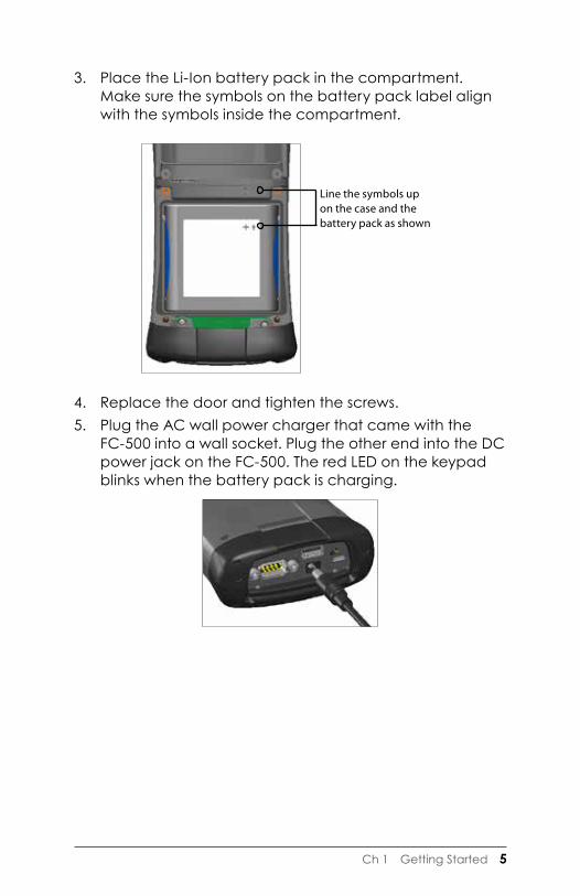
3. Place the Li-Ion battery pack in the compartment. Make sure the symbols on the battery pack label align with the symbols inside the compartment.
4. Replace the door and tighten the screws. 5. Plug the AC wall power charger that came with the
FC-500 into a wall socket. Plug the other end into the DC power jack on the FC-500. The red LED on the keypad blinks when the battery pack is charging.
Line the symbols up on the case and the battery pack as shown

6 FC-500 Handheld Field Controller Owner’s Manual
Attach the Stylus Tether A capacitive stylus and tether are included with the handheld.
Note: A stylus is not required to use the touchscreen. The optimal way to make selections is by finger touch.
One end of the tether is attached to the stylus. To attach it to the hand strap, follow these steps:
1. Pull the free tether loop through the tether ring on the hand strap. Insert the stylus with the attached tether through this loop and tighten the loop.
2. Place the stylus into the holder on the hand strap.
Perform Set Up and Charge the Battery1. The handheld powers on and begins the startup
process. A splash screen is shown that includes a progress indicator at the bottom of the screen.
2. A Microsoft® Windows Embedded Handheld screen is shown.
3. The Clock and Alarms control panel appears. Adjust the time zone, date and time if necessary and tap OK.

Ch 1 Getting Started 7
The Home screen appears (layout varies by model).
4. Press the power button to suspend the handheld. Charge the battery pack at room temperature (68° F or 20° C) for 4 to 5 hours. While the battery pack is charging, the red LED blinks. When it is fully charged, the red LED is solid.
Install the Operating System in Other Languages The operating system is provided in English by default. It is also available in other languages. You can download the operating system from www.TopconTotalCare.com.

8 FC-500 Handheld Field Controller Owner’s Manual
Home Screen and Windows Start MenuYou need to be familiar with two screens as you read this manual and use the FC-500: the Home screen and Windows Start menu.
Note: The Windows soft key switches back and forth between the Home screen and Windows Start Menu.
Home ScreenThe Home screen is your main control center for the FC-500. The content varies based on which model you have and can be customized. It is automatically shown when the FC-500 is turned on. You can get to it from any other screen by pressing and releasing the Home screen button on the keypad.
Windows Start MenuThe Windows Start menu gives you access to all of the applications on the FC-500. You can get to it from any screen by tapping the Windows tile (soft key) on the display or pressing the Home button on the keypad.
More information about these screens is located in Chapter 3, Programs and Settings.
Home Screen Windows Start Menu
Title Bar
Dashboardwith FunctionGadgets
Applications
Shortcuts to Favorite Applications
Tiles/Soft Keys

Ch 1 Getting Started 9
Navigating Around Your FC-500Using Gestures and Making SelectionsThe Windows® Embedded Handheld operating system enhances the ability of the handheld to recognize touch gestures, making it easy to use a finger to navigate. Use of the capacitive stylus is an option. The keypad buttons can also be used.
Navigation options vary depending on the screen you are viewing. Here is a partial list of options:
Vertical and Horizontal Movement � Flick up, down or sideways on the touchscreen. � For more precise positioning, touch, hold, and move the
screen up or down. � Use the scroll bar if it is available. � Use the up down right and left arrows on the
keypad to move around on a screen. � A horizontal scrolling menu is located on control panel
screens near the top. Press the left or right arrow keys to scroll through the topics. (This feature replaces tabs.)
Make a Selection Using the Touchscreen
� Press or tap the function gadget or application icon you want to select, turn on, activate, or turn off.
� Press and hold a function gadget to bring up a control panel, menu, or list.
Using the KeypadUse the up down right and left keys arrow on the keypad to select (highlight) a gadget or icon on the screen. A ring appears around the selection. System Info has been selected below:
10 FC-500 Handheld Field Controller Owner’s Manual
Perform the selected action by pressing the enter button. For dashboard gadgets like Wi-Fi, one press of the enter button shows you which icon is selected, a second press performs the action, and a third press turns the action off. For application icons on the Start screen or in favorites, continue to use the return button until you get to the screen or menu you want.
Updates to the Operating System and DocumentsUpdates to the operating system and technical documents are located on our website at www.TopconTotalCare.com.
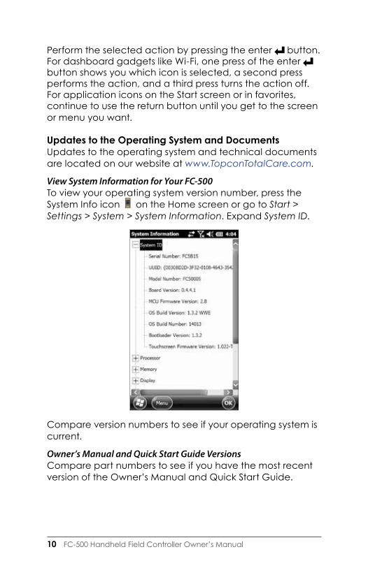
View System Information for Your FC-500To view your operating system version number, press the System Info icon on the Home screen or go to Start > Settings > System > System Information. Expand System ID.
Compare version numbers to see if your operating system is current.
Owner’s Manual and Quick Start Guide VersionsCompare part numbers to see if you have the most recent version of the Owner’s Manual and Quick Start Guide.
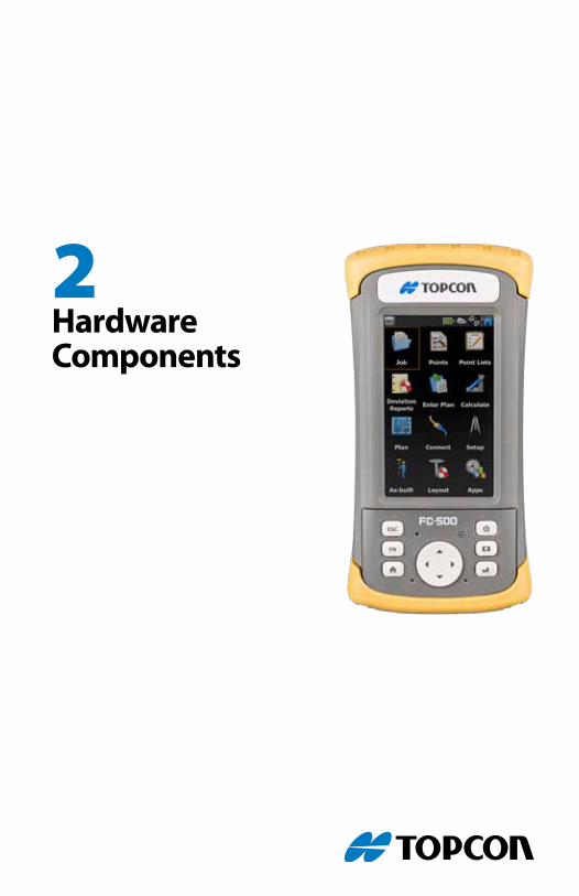
2Hardware Components
12 FC-500 Handheld Field Controller Owner’s Manual
Hardware ComponentsThis chapter discusses the FC-500 Handheld Field Controller hardware features and usage.
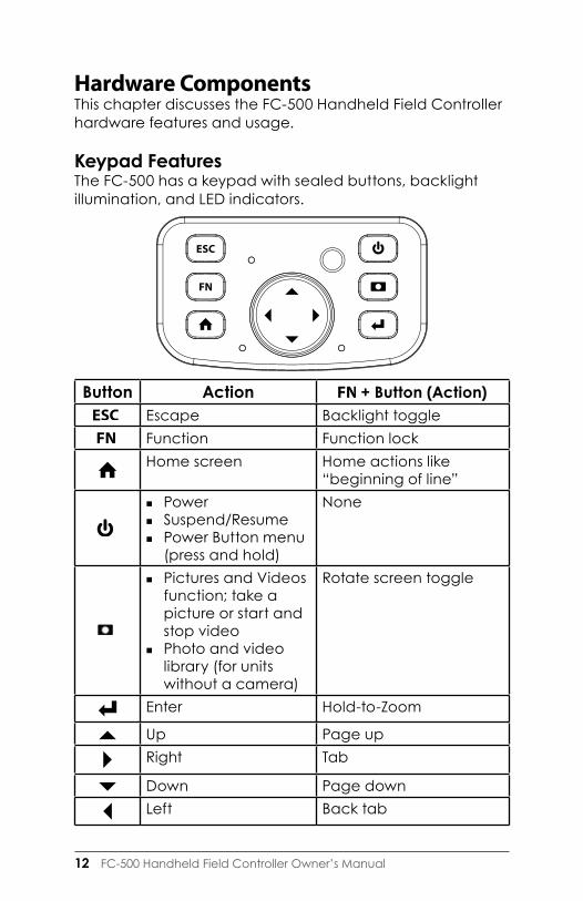
Keypad FeaturesThe FC-500 has a keypad with sealed buttons, backlight illumination, and LED indicators.
Button Action + Button (Action) Escape Backlight toggle Function Function lock
Home screen Home actions like
“beginning of line”
� Power � Suspend/Resume � Power Button menu
(press and hold)
None
� Pictures and Videos function; take a picture or start and stop video
� Photo and video library (for units without a camera)
Rotate screen toggle
Enter Hold-to-Zoom
Up Page upRight Tab
Down Page downLeft Back tab

Ch 2 Hardware Components 13
Programmable Function The FN-ESC function is programmable.
1. To bring up the Program Buttons control panel, select the Settings icon on the Home screen, and then Personal > Buttons. You can also go to the Start screen by selecting the Windows soft key and then select Settings > Personal > Buttons.
2. Select the FN-Esc function.

14 FC-500 Handheld Field Controller Owner’s Manual
3. At the bottom of the screen under 2. Assign a program, select the down arrow button to display a list of programs and functions. Select the item you want to reassign to the FN-Esc function.

Ch 2 Hardware Components 15
Keypad BacklightMake keypad brightness adjustments through the Backlight control panel located at Start > Settings > System > Backlight. Select the External Power screen or Battery Power screen from the horizontal menu near the top of the screen.
Move the Keypad slider up to brighten the backlight or down to dim it. Dimming the keypad backlight saves battery power when the FC-500 is in use.
Note: The keypad backlight turns off when the display backlight dims or the FC-500 is suspended.

16 FC-500 Handheld Field Controller Owner’s Manual
Display and TouchscreenThe FC-500 has a bright color display and capacitive touchscreen with a diagonal viewing area of 4.3 inches (109 mm). It is easy to view outdoors and is sealed against water and dust. The Windows® Embedded Handheld operating system enhances the ability of the FC-500 to recognize touch gestures, making it easy to use a finger to make selections and navigate. You can also use a capacitive stylus.
Display SettingsType and OrientationTo adjust the display settings, including the text size and orientation, go to the Screen control panel by pressing Start > Settings> System > Screen.
The screen is designed to be used in portrait orientation. A landscape orientation could impact the performance of an application.
Note: Capacitive touchscreens do not need to be aligned. Ignore the Align Screen option.

Ch 2 Hardware Components 17
Touchscreen ModesThe touchscreen is optimally designed for finger use. The default touchscreen mode can be adjusted to best match your application and environment, especially if you are using a capacitive stylus.
To adjust the touchscreen profile, go to the Touch control panel by pressing Start > Settings > System > Touch. Modes for finger or stylus use are shown. The higher the number between 10, 20, and 30 the greater the sensitivity.
Select the preferred mode, and tap Load. Do not interrupt the loading process. You can try different modes to see which one works best for you.

18 FC-500 Handheld Field Controller Owner’s Manual
Zooming in on the DisplayZooming in on the display increases the view by 50 percent and makes selecting content much easier.
Zoom options: � Hold-to-Zoom - Press and hold the + buttons on the
keypad (the default setting), and tap on the screen in the area on which you want to zoom. The screen focuses on that location. Make selections as desired. Release the buttons to return to the regular screen size.
� Magnifying glass - Tap on the title bar at the top of the screen to display the pop-up icons. Select the magnifying glass on the left.
This zooms in on the content. Move the screen around with your finger until you find the information you want. Select the magnifying glass symbol in the upper right corner of the screen to return the view to the regular size.

Ch 2 Hardware Components 19
Display Backlight Brightness SettingsThe default setting for the display backlight is 80%. Adjust the display brightness through the Backlight control panel by pressing Start > Settings> System > Backlight. External Power and Battery Power are adjusted on different screens. Select these screens from the horizontal scrolling menu near the top of the screen.
Move the Display slider up to brighten the backlight or down to dim it.
Dimming the Display AutomaticallyThe display has a minimum brightness setting that it dims to when the FC-500 is idle for the time interval indicated. The display backlight dims by 50%, so the display is still partially visible. You can adjust the dim time interval (see the previous screen) for battery and/or external power. Dimming the display backlight saves battery power.
To bring the backlight back up to the full brightness setting, tap on the dimmed display.
Note: The FC-500 can be set up in subdued lighting (tactical) mode. Refer to Chapter 3 for instructions.

20 FC-500 Handheld Field Controller Owner’s Manual
Turning the Screen Off AutomaticallyYou can set up the display backlight to turn off after set intervals. Tap on the top title bar from any screen, and select the battery icon from the list of applications that appears.
Alternately, go to the Backlight control panel, Start > Settings > System > Backlight. Near the bottom of the screen it says “Adjust Power Settings to conserve power.” Select the hyperlink power (see the previous screen shot).
The Power control panel appears. Select Advanced from the horizontal scrolling menu near the top of the screen. For battery and external power select how long the screen stays on when it is not in use. Shorter times save battery power.
Disabling and Enabling the TouchscreenYou can disable the touchscreen. This is useful when you are running an application and you want to see the screen while avoiding accidental touchscreen activation. The touchscreen can also be disabled for cleaning purposes.
Ch 2 Hardware Components 21
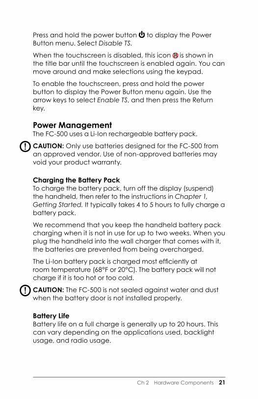
Press and hold the power button to display the Power Button menu. Select Disable TS.
When the touchscreen is disabled, this icon is shown in the title bar until the touchscreen is enabled again. You can move around and make selections using the keypad.
To enable the touchscreen, press and hold the power button to display the Power Button menu again. Use the arrow keys to select Enable TS, and then press the Return key.
Power ManagementThe FC-500 uses a Li-Ion rechargeable battery pack.
CAUTION: Only use batteries designed for the FC-500 from an approved vendor. Use of non-approved batteries may void your product warranty.
Charging the Battery PackTo charge the battery pack, turn off the display (suspend) the handheld, then refer to the instructions in Chapter 1, Getting Started. It typically takes 4 to 5 hours to fully charge a battery pack.
We recommend that you keep the handheld battery pack charging when it is not in use for up to two weeks. When you plug the handheld into the wall charger that comes with it, the batteries are prevented from being overcharged.
The Li-Ion battery pack is charged most efficiently atroom temperature (68°F or 20°C). The battery pack will not charge if it is too hot or too cold.
CAUTION: The FC-500 is not sealed against water and dust when the battery door is not installed properly.
Battery LifeBattery life on a full charge is generally up to 20 hours. This can vary depending on the applications used, backlight usage, and radio usage.
!
!

22 FC-500 Handheld Field Controller Owner’s Manual
To see the remaining battery power, tap on the top title bar from any screen and select the battery icon from the list of applications that drops down.
The Power control panel appears, displaying the remaining battery power.
Battery packs last approximately 1,000 to 3,000 charging cycles before they need to be replaced. This is impacted by applications and environmental factors.
Summary of Options to Reduce Power UsageYou can adjust some settings to preserve power:
� Turn off the display (suspend) after a set interval. See Display Backlight Suspend Interval earlier in this chapter.
� Dim the backlight after a set interval. See Adjusting the Keyboard Backlight and Adjusting the Display Backlight earlier in this chapter.
� Disable radios when not in use. Turn radios off from the
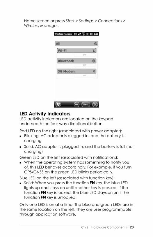
Ch 2 Hardware Components 23
Home screen or press Start > Settings > Connections > Wireless Manager.
LED Activity IndicatorsLED activity indicators are located on the keypad underneath the four-way directional button.
Red LED on the right (associated with power adapter): � Blinking: AC adapter is plugged in, and the battery is
charging � Solid: AC adapter is plugged in, and the battery is full (not
charging) Green LED on the left (associated with notifications):
� When the operating system has something to notify you of, this LED behaves accordingly. For example, if you turn GPS/GNSS on the green LED blinks periodically.
Blue LED on the left (associated with function key): � Solid: When you press the function key, the blue LED
lights up and stays on until another key is pressed. If the function key is locked, the blue LED stays on until the function key is unlocked.
Only one LED is on at a time. The blue and green LEDs are in the same location on the left. They are user programmable through application software.

24 FC-500 Handheld Field Controller Owner’s Manual
FlashlightGeo units have a flashlight located underneath the camera window in the back of the FC-500. This is also the camera flash.
The flashlight gadget must be on the Home screen in order to use it. Tap on the icon once to turn on the brightest illumination. Tap the gadget again for medium brightness, and a third time to turn it off.
SD Cards The FC-500 has a slot for a micro SD card located in the battery compartment. To insert or remove a card follow these steps:
1. Power off the handheld.2. Loosen the screws to the battery compartment, and
remove the door. The hand strap remains attached. CAUTION: The FC-500 is not sealed against water and
dust when the battery door is not installed properly. 3. Remove the battery pack.4. An image on the battery compartment label shows the
correct location and orientation for the SD card (slot on the right). Push the card into the slot to insert it. To remove the SD card, pull it out.
5. Replace the battery pack, and attach the battery door.6. Power up the handheld.
!

Ch 2 Hardware Components 25
Connector I/O Module The FC-500 connector I/O module has the following jacks, connectors, and connector protector:
The connector module is user-replaceable. Contact our sales department or your supplier for details.
Audio FeaturesThe FC-500 has the following audio features:
� Speaker - The speaker sound is loud and clear. Listen to audio notes, video sound, and music files.
� Microphone - Use the microphone to record audio notes or add sound to a video when using the camera function (option).
� Audio Jack - The audio jack supports a stereo headset or headset/microphone combination with 3.5mm connections.
Adjusting Audio SettingsTo set audio options, tap on the top title bar and select the audio icon from the list of applications that drops down. Or, press Start > Settings > System > Audio.
2 3 4
5
1 USB Client, Micro
2 Microphone/Speaker Jack
3 USB Host, Full Size
4 9-pin Serial Port
5 12V DC Jack
6 Connector Protector (connectors are sealed from water ingress without a connector protector)
1
6

26 FC-500 Handheld Field Controller Owner’s Manual
The Audio control panel, Output screen, is shown:
From the Output screen you can adjust the speaker options. Select the Input screen from the horizontal menu near the top of the screen. You can adjust the onboard and headset microphones as desired.

3Programs and Settings

28 FC-500 Handheld Field Controller Owner’s Manual
Programs and SettingsThis chapter discusses the FC-500 Handheld Field Controller programs and settings.
Home ScreenThe Home screen is your main control center for the FC-500. View vital system information and quickly access functions and applications that are frequently used. The default home screen for a basic unit is shown below. Different functions are shown depending on which model you have. You can customize the Home screen.
You can get to the Home screen from any screen by pressing the Home button on the keypad. Tap on a gadget or icon to turn a function or application on or off. Tap and hold a gadget to go to a control panel. From the keypad you can use the up down right and left arrow keys to select (highlight) a gadget or an icon on the screen. Perform the selected action by pressing the enter button.
Title Bar
Dashboard
Favorites
Tile Bar

Ch 3 Programs and Settings 29
Title Bar and Pop-Up Icons The title bar is at the top of every screen. It identifies the page and shows status icons indicating functions like connectivity status, audio, power, and time. Tap the title bar to bring up larger, touchable icons in a horizontal-scrolling bar. Select a function to use or to view the settings and adjust them as desired.
DashboardThe dashboard consists of a background image and up to six dashboard gadgets that serve as functional indicators and control buttons.
You can switch between two color schemes and select which gadgets are shown. Tap on the menu soft key and select Switch Color Scheme to change color schemes or Configure to select gadgets. The current gadgets are covered with a blue symbol as shown below.
Tap on the gadget you want to replace. A list of available dashboard gadgets is shown. Tap on your new selection. The dashboard icon changes when you make a selection. If
Pop-Up Icons
Title Bar

30 FC-500 Handheld Field Controller Owner’s Manual
“None” is selected, the space becomes blank.
Dashboard Gadget Functions
Wi-Fi: Shows the state of the Wi-Fi radio and provides the name of the wireless network to which it is attached.
Bluetooth® wireless technology: Shows the state of the Bluetooth radio.
Email: Shows the number of unread email messages. If there are multiple email accounts, the total number of unread messages is aggregated from all accounts.
Calendar: Shows the next appointment.
Tasks: Shows the current number of tasks.
GPS/GNSS Status (Geo model): Shows the current state of GPS/GNSS reception and the state of the GPS/GNSS receiver. It also shows the number of satellites in view, the number of satellites used to calculate the fix (SV), the type of fix (2D, 3D, etc.), and the quality of the fix (PDOP).
JSNav (Geo model): An application that lets you easily collect waypoint or track data and navigate back to any saved waypoint or track.
3G Data Modem (Geo model with cell modem): Shows the on/off state of the optional cellular modem.Flashlight: Shows the on/dim/off state of flashlight feature (included with camera).
Ch 3 Programs and Settings 31
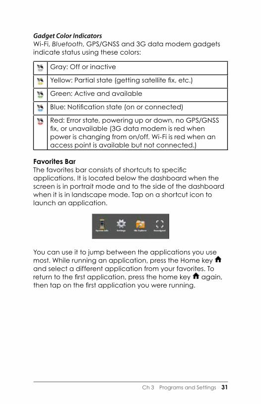
Gadget Color IndicatorsWi-Fi, Bluetooth, GPS/GNSS and 3G data modem gadgets indicate status using these colors:
Gray: Off or inactive
Yellow: Partial state (getting satellite fix, etc.)
Green: Active and available
Blue: Notification state (on or connected)
Red: Error state, powering up or down, no GPS/GNSS fix, or unavailable (3G data modem is red when power is changing from on/off. Wi-Fi is red when an access point is available but not connected.)
Favorites BarThe favorites bar consists of shortcuts to specific applications. It is located below the dashboard when the screen is in portrait mode and to the side of the dashboard when it is in landscape mode. Tap on a shortcut icon to launch an application.
You can use it to jump between the applications you use most. While running an application, press the Home key and select a different application from your favorites. To return to the first application, press the home key again, then tap on the first application you were running.

32 FC-500 Handheld Field Controller Owner’s Manual
You can customize which application shortcuts are shown. Tap and hold on the shortcut you want to change to bring up a list of available applications.
Tap on your selection. The icon on the home screen changes to the icon associated with the new application.
Tile BarTouchable tiles (or soft keys) are shown in the tile bar at the bottom of each screen. Up to five tiles are shown, depending on which screen you are on.
For example, the Home screen tile bar (shown below) consists of: 1) the Microsoft start tile that takes you to the Start menu, 2) the back tile that takes you to the last application running, and 3) the menu tile that lists options for customizing the dashboard. The third and fifth tile positions are empty.
Tap on a tile to perform the actions associated with it.
Ch 3 Programs and Settings 33
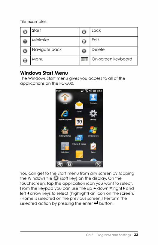
Tile examples:
Start Lock
Minimize Edit
Navigate back Delete
Menu On-screen keyboard
Windows Start MenuThe Windows Start menu gives you access to all of the applications on the FC-500.
You can get to the Start menu from any screen by tapping the Windows tile (soft key) on the display. On the touchscreen, tap the application icon you want to select. From the keypad you can use the up down right and left arrow keys to select (highlight) an icon on the screen. (Home is selected on the previous screen.) Perform the selected action by pressing the enter button.

34 FC-500 Handheld Field Controller Owner’s Manual
On-Screen KeyboardTo activate the on-screen keyboard, select the keyboard tile located at the bottom of active applications like Notes that use keyboard input.
The default keyboard is Mega Keys, featuring large keys and increased functionality.
To view and select other options including Block Recognizer, Letter Recognizer, and Mega Keys Night, press and hold the keyboard tile . To turn the on-screen keyboard off, press the keyboard tile.
Mega Keys (and Mega Keys Night) Keyboard Features � Pressing on a character with a finger or stylus highlights it.
Releasing the key prints the character on the screen. � If you accidentally press the wrong character and have
not released the key yet, you can slide to the correct character before releasing the key.
� There are four main keyboard screens: lowercase, uppercase, numeric, and symbols. To navigate to different screens, press the modifier keys in the lower left corner of each screen as shown in the following example for the lowercase keyboard. Press the up arrow to go to

Ch 3 Programs and Settings 35
the uppercase keyboard, the number key to go to the numeric keyboard, and the symbol key to go to the symbols keyboard.
� Tap on the shift key for a single uppercase letter. Tap on the shift key twice to lock uppercase on. Tap once more to return to the lowercase keyboard.
� To enter a character from another screen (such as a number or symbol), press and hold on the modifier key, slide to the character you want, then release the key. The character is printed, and you are returned to the screen you started from.
� Some keys have an extra character bar that includes items like accented characters or additional symbols. These keys have three dots in the bottom right corner like the z key . Press and hold the key to bring up the extra bar. Tap the desired item or dismiss the bar by tapping outside of the bar.
� A calculator is available from the numeric screen. Press the Calc key to launch the calculator application.
� The backspace and the space keys can be repeated by pressing and holding those keys.

36 FC-500 Handheld Field Controller Owner’s Manual
Suspend, Reset, Power Off, and Restore Defaults Use the power button to suspend, reset, power off, or restore the FC-500 to its factory state. To access the Power Button menu, press and hold the power button.
Suspending and Resuming the FC-500We recommend suspending your handheld if you plan to turn it off for less than two weeks. While it is suspended, you should attach it to a wall charger when it is not in use.
Suspending the handheld is different from powering it off. When the device is suspended it goes into a very low power mode. Some battery power is used during suspend.
1. Press and release the power button . The backlight shuts off. It can take several seconds to fully suspend, especially when the cell modem is on.
2. To resume the device from suspend mode, press and release the power button again. When it is resumed, the handheld resumes where it was before it was suspended.
3. There is also a Suspend option on the Power Button menu.

Ch 3 Programs and Settings 37
Resetting the FC-500If the FC-500 is unresponsive, slow, or programs won’t launch, performing a reset might solve the issue. You may be asked to perform a reset when an application is installed.
CAUTION: Be aware that during a reset, applications are closed and unsaved work may be lost.
Follow these steps to reset your FC-500:
1. Save open files, and close any running programs.2. Press and hold the power button until the Power
Button menu appears.3. Tap Reset.You can also reset the handheld by pressing the power button for 10 seconds or until the screen goes dark. After a few seconds, the handheld automatically turns on. This method is useful if your FC-500 locks up.
Powering Off and On the FC-500To preserve battery power, we recommend you power off the FC-500 if it will not be used for two weeks or longer.
CAUTION: Be aware that when the FC-500 is powered off, it closes all programs and powers down all system components except for the real-time clock. Unlike suspend mode, the device resets when it is powered on again. Any unsaved data is lost.
1. Save open files, and close any running programs.2. If you are using external power, unplug it.3. Press and hold the power button until the Power
Button menu appears.4. Tap Power Off. A warning dialog appears. Tap OK.To power on your handheld, press the power button.
Restoring the FC-500 to its Factory State (Clean Boot)Follow the steps below to restore user storage, settings, and icons on your FC-500 to their original factory defaults.
!
!
38 FC-500 Handheld Field Controller Owner’s Manual
CAUTION: Restoring the FC-500 to its original factory state permanently erases data saved on the handheld, any software you installed, and any changes you made to the handheld, including changes to settings.
1. Back up files and programs you want to keep onto another computer.
2. Save open files and close running programs on the handheld. Press and hold the power button until the Power Button menu appears. Tap Reset.
3. When the screen turns black, press and hold the power button again. The bios screen is shown.
4. Move the top slider on the screen to the right to set or clear factory defaults. This clean boots the handheld.
5. Tap Exit. The boot process continues.
Subdued Lighting (Tactical) ModeIn some environments subdued lighting is preferred. The display backlight, LEDs, and keypad illumination can be subdued during the startup process and normal operation.
Set Up During a Reset1. Save open files and close running programs on the FC-
500. Press and hold the power button until the Power Button menu appears. Tap Reset.
2. When the screen turns black, press and hold the power button again. The bios screen is shown.
3. Move the slider on the screen to the right to turn the tactical mode on.
4. Tap Exit. The boot process continues.To restore the handheld to default lighting, follow the same steps.
Adjust the Backlight Control PanelYou can also subdue the keypad and display brightness through the Backlight control panel. Press Start > Settings> System > Backlight and then External Power or Battery Power from the horizontal scrolling menu near the top of the
!

Ch 3 Programs and Settings 39
screen. Adjust the sliders as needed for both power sources. Changes affect all operations.
Use Buttons on the KeypadYou can toggle the backlight brightness up or down using the + keys. The brightness level is based on the minimum and maximum settings set up through the Backlight control panel.
Compass and Accelerometer CalibrationThe FC-500 has a built-in compass and accelerometer. The compass is used for embossing GPS/GNSS information on pictures taken with the camera, or embedding GPS/GNSS information into jpg files. The compass is also used by the JSNav program. The accelerometer assists the compass in determining direction, even when the device is not resting flat. (See Chapter 6, GPS/GNSS, JSNav Application and Chapter 7, Camera, Geotagging.)
The compass and accelerometer can also be used by other user applications.

40 FC-500 Handheld Field Controller Owner’s Manual
Sensors Control PanelThe Sensors control panel lets you see the compass and accelerometer working, set the magnetic declination angle, and calibrate the sensors. Press Start > Settings > System > Sensors.
� The Magnetic Declination angle is the difference between true north and magnetic north. Applications that are using true north use this value to adjust the readings from the compass.
� To calibrate the compass, press Calibrate Compass. Rotate the handheld around all three axis several times in every orientation possible (for at least 10 seconds). Press Stop when you are done. Calibrating the compass is very important and needs to be done often. Changes in environment, added attachments to the handheld, and mounting options can affect the sensor readings. If you are mounting the handheld to a pole, mount it first and then calibrate the compass.
� When the accelerometer is calibrated, you are telling the handheld that this is level, remember this. It is important that the handheld is laying on its back on a level surface. If the stylus holder on the hand strap makes the handheld uneven, you can try placing it on two equal-

Ch 3 Programs and Settings 41
sized blocks, one placed on each end. The blocks must be high enough for the stylus holder to drop in between them. When the handheld is level, press Calibrate Accelerometer, and then Start. Samples are averaged over the next five seconds and the result is saved. The accelerometer only needs to be calibrated once. (If you restore the handheld to its original factory defaults, you need to calibrate the accelerometer again.)
Communicating with a ComputerThe FC-500 can connect to a desktop or laptop computer, allowing you to synchronize information and download software and files.
Installing the Software Install free synchronization software from Microsoft on your desktop computer.
1. Go to the Microsoft website on your computer at http://www.microsoft.com/en-us/download/.
2. If your computer is running Windows® 2000 or Windows® XP, search for and select ActiveSync® software to download. If it is running Windows Vista™, Windows® 7, or Windows® 8, search for and select Windows Mobile® Device Center software.
3. Follow the download instructions on the website.
Establishing a Partnership1. Plug the USB Client end (micro B) of the USB
communications cable into the FC-500.2. Plug the USB Host end (full size A) of the USB
communications cable into your computer.3. Establish an ActiveSync® or Windows Mobile® Device
Center partnership by following the instructions on the computer screen.
4. Once a partnership is established, the synchronization software automatically opens. Follow the steps on the screen.

42 FC-500 Handheld Field Controller Owner’s Manual
Getting Started Application Getting Started ScreenThe Getting Started screen provides information on current settings, help for setting up features and applications, and shortcuts to set up screens. To see a list of topics press Start > Getting Started.

4Bluetooth Wireless Communication

44 FC-500 Handheld Field Controller Owner’s Manual
Bluetooth® Wireless CommunicationThe FC-500 has built-in Bluetooth® wireless technology, allowing you to connect it to other wireless devices with Bluetooth technology. Minimum performance between similar objects in an unobstructed environment is approximately 100 feet (30 meters).
The handheld provides simple configuration options for the following types of Bluetooth devices:
� Devices such as headphones, keyboards, and modems (to connect to the Internet with an external cell phone).
� Serial devices that use a Bluetooth COM port, such as GPS/GNSS receivers, bar code scanners, and other data collection devices.
Creating a PartnershipTo create a partnership between the FC-500 and another device with Bluetooth technology:
1. Turn both devices on. 2. Place them within at least 100 feet (30 meters) of one
another.3. Make Bluetooth discoverable on both devices. Bluetooth
on the FC-500 is on and discoverable by default. The gadget on the Home screen turns green.

Ch 4 Bluetooth Wireless Communication 45
If the Bluetooth gadget is not on your Home screen, you can get to the desired control panel by selecting Getting Started and either Set up a Bluetooth device or Set up a Bluetooth COM Port. You can also press Start > Settings > Connections.
Note: If the Bluetooth radio is turned on and then the handheld is suspended, wireless Bluetooth turns off to save battery power. When the FC-500 resumes (turns on), the radio turns on automatically.
Bluetooth Control PanelTo create a partnership with and connect to other Bluetooth devices, such as such as headphones, keyboards, and modems, follow these steps:
1. Tap-hold the Bluetooth icon to bring up the dialog box shown below.

46 FC-500 Handheld Field Controller Owner’s Manual
2. Select the Headphones, Modem, Keyboard. The following Bluetooth control panel, Devices screen is shown:
3. Tap Add New Device. The FC-500 searches for other devices with wireless Bluetooth technology and displays them in a list. Select the device you want to connect to, and tap Next.
4. A passcode screen is shown.

Ch 4 Bluetooth Wireless Communication 47
a. If the device has an assigned passcode, enter the number and press Next.
b. If a passcode is required but has not been assigned, enter an alphanumeric passcode between 1 and 16 characters in length. Press Next.
c. If a passcode is not required, leave the box blank and press Next.
Note: If you are unsure whether or not the device requires a passcode and if one has already been assigned to the device, see the user documentation that came with the device.
5. You can adjust the Bluetooth settings as needed.
Serial Device (COM) Control PanelTo set up a Bluetooth COM port, follow these steps:
1. Select COM Port, GPS, RFID from the Bluetooth dialog box. The following Bluetooth COM configuration screen is shown. Select Discover Devices.
2. After the handheld searches, a list of discovered devices is shown. Select the device you want to connect to from

48 FC-500 Handheld Field Controller Owner’s Manual
the list and tap Connect. A COM port is automatically assigned for the device. You can change it to another COM port if desired.
3. The FC-500 automatically tries to discover the PIN. You might be required to enter a PIN.
You should now be connected to the COM device.

5Wi-Fi Wireless Networking
50 FC-500 Handheld Field Controller Owner’s Manual
Wi-Fi Wireless NetworkingThe FC-500 has built-in Wi-Fi wireless networking to connect to the Internet or a office network.
Connecting to a Wi-Fi NetworkTo use Wi-Fi, you need to be in range of a Wi-Fi access point to make a connection. To actively look for a network connection complete the following steps:
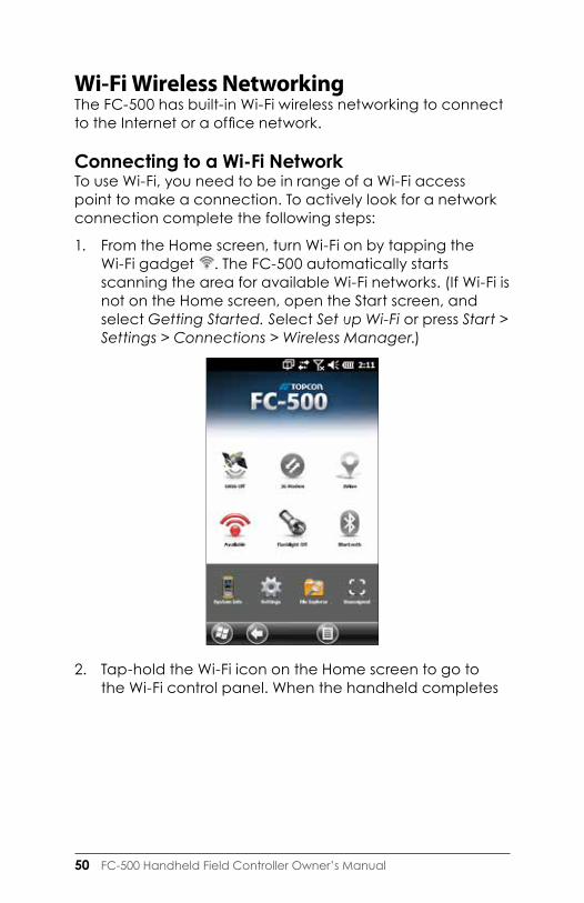
1. From the Home screen, turn Wi-Fi on by tapping the Wi-Fi gadget . The FC-500 automatically starts scanning the area for available Wi-Fi networks. (If Wi-Fi is not on the Home screen, open the Start screen, and select Getting Started. Select Set up Wi-Fi or press Start > Settings > Connections > Wireless Manager.)
2. Tap-hold the Wi-Fi icon on the Home screen to go to the Wi-Fi control panel. When the handheld completes

Ch 5 Wi-Fi Wireless Networking 51
the scan, a list of available networks and their strengths appears on the Wi-Fi Wireless screen.
3. Tap on the network to which you want to connect. If you want to add a new network, select Add New from the top of the list.
4. Configuration and authentication setup screens are shown. Depending on the network you are connecting to, you may need to make some selections from pull down lists and enter information like a passkey. Some information may not be required or will appear automatically. When you are finished with the set up screens, press Finish.
5. Select Network Adapters from the horizontal scrolling menu near the top of the screen. For connection options, select The Internet or Work (for office networks). Other settings can be modified if necessary.
6. If you selected The Internet, you can open Internet Explorer and begin using the Internet.
Once a Wi-Fi network is set up, the icon on the Home Page turns blue and the name of the network is shown.
The FC-500 remembers the Wi-Fi network connections created.
52 FC-500 Handheld Field Controller Owner’s Manual
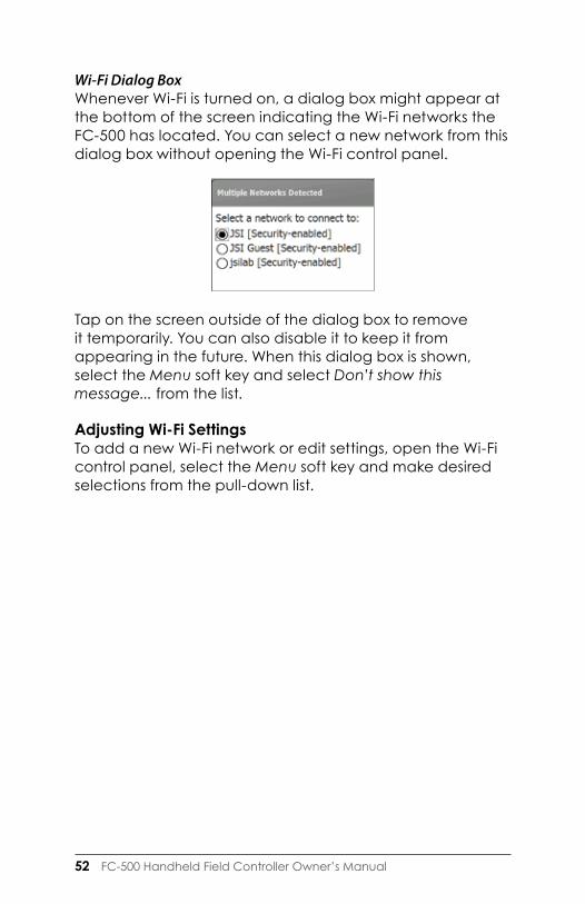
Wi-Fi Dialog BoxWhenever Wi-Fi is turned on, a dialog box might appear at the bottom of the screen indicating the Wi-Fi networks the FC-500 has located. You can select a new network from this dialog box without opening the Wi-Fi control panel.
Tap on the screen outside of the dialog box to remove it temporarily. You can also disable it to keep it from appearing in the future. When this dialog box is shown, select the Menu soft key and select Don’t show this message... from the list.
Adjusting Wi-Fi Settings To add a new Wi-Fi network or edit settings, open the Wi-Fi control panel, select the Menu soft key and make desired selections from the pull-down list.

6GPS/GNSS

54 FC-500 Handheld Field Controller Owner’s Manual
GPS/GNSSFC-500 Geo models have GPS/GNSS with 2 to 5 meter accuracy.
Using GPS/GNSSTo use GPS/GNSS, tap on the GPS/GNSS status gadget to turn it on. The GPS/GNSS starts looking for satellites to use for a fix. The green LED on the keypad blinks periodically, and a satellite icon appears on the title top bar.
Once enough satellites are found, information similar to the following is shown:
5 SV The number of satellites used for the current position.

Ch 6 GPS/GNSS 55
3Diff The type of fix you have. Three satellites are required for a 2D fix while four are required for a 3D fix. 3Diff means an SBAS (WAAS/EGNOS/MSAS) signal is being used for the GPS/GNSS solution.
PDOP A measure of accuracy. The lower the number, the more accurate the fix is.
Note: When you suspend the FC-500, the receiver is in a low power mode to retain its almanac. When you resume the FC-500, it takes a few seconds to get a fix.
GPS/GNSS SettingsTo view or make changes to the GPS/GNSS settings or set up an external GPS/GNSS, press and hold the GPS/GNSS status gadget on the Home screen to go to the control panel.
Select the programs port, hardware port and baud rate (internal GPS/GNSS uses COM8 at 115200 baud), program access, data format, NMEA sentences, satellite systems and module settings (update rate, baud rage, filter).
Several applications can share the COM port setup as the GPS/GNSS program port using the GPS/GNSS Intermediate Driver (GPSID).

56 FC-500 Handheld Field Controller Owner’s Manual
GPS Intermediate DriverThe GPS Intermediate Driver (GPSID) is used to allow more than one program to use data from the GPS/GNSS receiver. The GPS/GNSS Settings control panel controls how the GPSID is used. Internal GPS/GNSS is on COM8 and communicates at 115200 baud. These settings are found on the Hardware screen of the GPS/GNSS Settings control panel. If another GPS/GNSS receiver is to be used, this is where you connect that GPS/GNSS receiver so that the GPSID can access it.
The GPSID can output data on another COM port in a way that allows multiple programs to access the same COM port. This is called the Program Port and defaults to COM2. This can be set up on the Programs screen of the GPS/GNSS Settings control panel.
The camera, GPS/GNSS function and JSNav function use the GPSID to obtain GPS/GNSS information. Turning off the GPSID through the GPS/GNSS hardware port disables these functions.
Note: If an application accesses the GPS/GNSS module directly on COM8, the GPSID will not have access to the GPS/GNSS. This prevents the camera geotagging and GPS/GNSS from functioning.
GPS/GNSS AccuracyThe GPS/GNSS antenna is in the top of the FC-500. Do not put your hand or another object over the cap. This reduces accuracy. The more items between you and the satellites, the lower the accuracy.

Ch 6 GPS/GNSS 57
JSNav ApplicationJSNav is a GPS/GNSS application that lets you easily collect waypoint or track data.
Note: Calibrate the compass and accelerometer before you use JSNav. Refer to Chapter 3, Programs and Settings, Compass and Accelerometer Calibration.
From the Home screen tap on the JSNav gadget . A splash screen appears while the application opens, and then the main JSNav screen appears. Tap on the satellite icon in the upper right corner to turn GPS/GNSS on or off. (A gray icon means GPS/GNSS is not connected, red means there is no fix, yellow means a 2D fix, and green means a 3D fix.)
Once there is a fix (this may take a few minutes) information about the current position is given as well as PDOP (position dilution of precision), EHE (estimated horizontal error), and the number of satellites used for a fix. The bottom portion of the screen is used to collect waypoint or track data.

58 FC-500 Handheld Field Controller Owner’s Manual
JSNav Settings Tap on the menu icon in the upper left corner of the screen, and select Settings from the list. Go through the menu options to set up JSNav.
Note: These settings only impact the JSNav application. To set up GPS/GNSS go to the GNSS Settings control panel discussed earlier in this chapter.
� Units: Select English or metric units of measurement and the display format for latitude and longitude.
� GPS Settings: Select the maximum PDOP for collecting points, minimum navigation speed you need to be traveling for navigation to update properly, and the navigation distance threshold. This is the distance you can be from the point to which you are navigating to show that you have arrived.
� Default File Type: Select .kml (keyhole markup language used in Google Earth) or .csv (comma separated value). Note that tracks with more than 1000 points default to .csv due to memory limitations.
� Waypoint Settings: Set up the waypoint file naming scheme, including the waypoint prefix, increment step size, and current value. For example, if the waypoint prefix is Point, increment step size is 10, current value is

Ch 6 GPS/GNSS 59
100, and default file type is .kml, file names would be Point110.kml, Point120.kml, Point130.kml, etc.) Also select the number of points to average. The default is 1.
� Track Settings: Set up the track file naming scheme (see Waypoint Settings). You can select a minimum time and minimum distance needed before a point is collected. If both are enabled, both conditions must be met before a point is added to a track. You can disable suspend when track points are being collected.
� Audio Notifications: You can turn on notifications for waypoint arrival, waypoint collected, and track point collected.
Some settings can be customized for a particular waypoint or track using edit on the data collection screens.
View Signal Strength and NMEA StringsView the strength of satellites being used in a fix (shown in green) by swiping the area where position is shown on the Home screen to the right. View the NMEA strings that are coming in through the GNSS receiver by swiping the same area to the left. Strings can be saved to a file.
Collect Waypoint DataFrom the main JSNav screen tap the waypoint icon to open the Collect Waypoint screen.

60 FC-500 Handheld Field Controller Owner’s Manual
� To collect a waypoint, tap the waypoint icon at the bottom of the screen. Position information for the waypoint is recorded.
� Tap the edit icon to add or edit the name, description, notes, and file type for this waypoint.
� To navigate back to the waypoint you just collected, tap the compass icon. A rotating compass is shown. Walk in the direction of the red arrow. The distance shown decreases as you get closer. Text saying Arrived is shown and you hear a beep (if audio notifications are set up) when you reach the navigation distance threshold set up in GPS Settings.
� Tap the disc icon to save the waypoint to \My Documents\My Waypoints.
Collect Track DataFrom the main JSNav screen tap the track icon to open the Collect Track screen.

Ch 6 GPS/GNSS 61
� To collect points in a track, tap the play button and start moving along the desired track. Tap the pause button as needed, and tap play to start again. Current position information, total distance, altitude change, and points in the track are collected.
� When you are finished, tap the stop button. A dialogue box is shown with the track name. You can use that name or edit it. Press the check mark when you are finished. The track is saved in \My Documents\My Tracks.
� Tap the edit icon to add or edit the name, description, notes, and file type for this track
Managing Waypoints and TracksTo view the waypoints and tracks you have saved, tap the menu icon, then select Waypoints or Tracks from the menu. A list of waypoints or tracks is shown.
To open a file, tap on the name. You can view collected data, select the file for exporting or deletion by tapping the box to the left of the name, navigate back to the waypoint or track points , delete the file , or edit the file. To select all of the files, tap the check box at the bottom of the screen. You can delete or export all selected files. Exported files are placed into a directory called Exports inside of your \My Documents folder.

62 FC-500 Handheld Field Controller Owner’s Manual
Importing Waypoints and TracksWaypoint and track file formats must be .kml, .kmz or .csv. CSV files must contain a column for both latitude and longitude.
To import a waypoint or track file, place the file into the \My Documents\My Waypoints or \My Tracks directory. You can create subdirectories to organize your data if you want. Once you place a waypoint or track file into the proper directory or subdirectory it appears in the list of waypoint or track files.
An imported track file can only contain one track if you are going to navigate to a specific track. If a file contains multiple tracks, a button inside of JSNav is available to extract the tracks into separate files.
Navigating to a Waypoint or TrackYou can navigate back to any saved waypoint or track. Select the file you want to navigate to as described in the previous section, Managing Waypoints and Tracks. Tap the compass icon.
A rotating compass is shown. Travel in the direction of the red arrow. The distance shown decreases as you get closer. When you reach the navigation distance threshold set up in the settings, text saying Arrived is shown and you hear a beep if audio notification has been set up.

7Camera

64 FC-500 Handheld Field Controller Owner’s Manual
CameraFC-500 Geo models have a 5MP camera and a video option. Geotagging gives you the ability to embed and emboss photos with the date, time, and GPS/GNSS position.
The camera window and flash are located on the back of the FC-500.
Note: The flash can also be used as a flashlight. See Chapter 2, Hardware Components, Flashlight.
Camera Settings for Still ImagesPress the camera button to turn the camera on and open the Pictures and Videos application.
Pictures MenuSelect the Menu soft key for a pull-down list of setting options. View or change the settings before you take photos. These settings will apply to all photos taken, but can be edited as needed.

Ch 7 Camera 65
FlashTo use the flash, select Flash from the Menu, then select On. The flash automatically turns on each time you take a photo. To turn it off, select Flash from the menu and select Off.
Pictures & Videos Control PanelTo view or change additional settings, select Options from the Menu soft key. The Camera control panel is shown. Use the horizontal scrolling menu near the top of the screen to see what the setting are and make changes as needed.
GeotaggingWhen pictures are geotagged, the date, time, latitude, longitude, file name, and notes can be included with the pictures with the emboss and embed options.
Note: Calibrate the compass and accelerometer before you use Geotagging. Refer to Chapter 3, Programs and Settings, Compass and Accelerometer Calibration.
Follow these steps:
1. Turn on GPS/GNSS by tapping the GPS/GNSS gadget on the Home screen and waiting for a fix.

66 FC-500 Handheld Field Controller Owner’s Manual
2. Select the Menu soft key, then select Geotag from the menu. The following Emboss Options screen is shown:
Select the information you want to emboss on pictures, the position, and the color.
The selected information is embossed on pictures, making it part of the images.

Ch 7 Camera 67
3. 3. You can build GPS/GNSS information into jpg files from the Embed Options screen. (This information does not appear on the images.) You can select Use True North.
Embed GPS allows you to put images into programs like Google Earth™ and sort them by location, etc. If you select User Note, the note screen is shown after a photo is taken. Enter a note for the image and press OK.

68 FC-500 Handheld Field Controller Owner’s Manual
Take Photos and Select Photo OptionsPress the camera button to turn the camera on. Frame the photo as desired (a portrait orientation works best) and press the camera button . A square yellow line is shown, indicating that the camera is in focus. A screen like the following is shown for a few seconds. Hold the handheld steady until you hear a click, indicating that the photo has been taken.
While the photo is being saved, a disk symbol is shown briefly. The full photo is then shown on the screen.

Ch 7 Camera 69
Photo OptionsSelect the Menu soft key to see a list of options for a particular photo. (The photo must appear on the screen.)
To take another photo, press the Camera soft key. To see a library of photos and pictures, press Thumbnails.

70 FC-500 Handheld Field Controller Owner’s Manual
VideosPress the camera button to turn on the camera. Select the Menu soft key, and select Video.
Press Menu again to view and adjust settings as desired.
Note: A portrait orientation is the default for videos.

Ch 7 Camera 71
Press the camera button to start recording a video. Press it again to end the video.
Note: To take photos instead of videos, press Menu and select Still (see previous screen).
AudioYou can record sound with videos. From the Pictures & Videos application screen, tap Menu > Video > Menu > Options. From the Video screen, tap Include audio when recording video files to turn audio on.
Photo and Video LibraryTo view your photo and video library select the Thumbnails soft key from the Pictures and Videos application screen.

72 FC-500 Handheld Field Controller Owner’s Manual
Library Menu OptionsSelect a photo or video, then the Menu soft key. You can send, delete, edit, etc. the selected photo or video.

83G Data Modem

74 FC-500 Handheld Field Controller Owner’s Manual
3G Data ModemThe 3G data modem is an option for FC-500 Geo models, adding Wide Area Network data modem capability. The modem is installed at the factory.
The modem is a cellular data modem, type GSM/UMTS. It is five band modem compatible. The modem operates in different modes, depending on the wireless provider and the signal strength. Data speeds will vary anywhere from 10 or 20 Kbps when using GPRS to over 1 Mbps when using HSDPA.
Set up a Data Account with a Wireless ProviderContact a wireless provider to set up data service for the cellular data modem and obtain an account and SIM card (purchased separately). You need to provide the following information when setting up an account:
1. Billing Information and business ID, such as your Federal Tax I.D. or VAT number.
2. The wireless services required. Specify that you need data service only. You do not need voice or messaging services.
3. You may be asked for the modem’s IMEI number, which can be found here: Start > Settings > System > System Information > 3G Modem with the modem powered on.
4. You may be asked to provide the modem’s model number. This number allows the carrier to verify this modem as one of its approved models. If asked for this by the carrier, it is a Topcon Positioning Systems FC-500.
Install the SIM CardTo insert or remove a card follow these steps:
1. Power off the handheld.2. The card slot is located in the battery compartment.
Loosen the screws to the door and remove it. CAUTION: Do not use a micro SIM adapter. The adapter
can get stuck and damage the slot.!
Ch 8 3G Data Modem 75
3. Remove the battery pack. CAUTION: The FC-500 is not sealed against water and
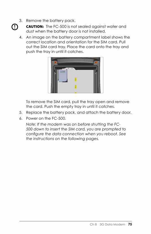
dust when the battery door is not installed. 4. An image on the battery compartment label shows the
correct location and orientation for the SIM card. Pull out the SIM card tray. Place the card onto the tray and push the tray in until it catches.
To remove the SIM card, pull the tray open and remove the card. Push the empty tray in until it catches.
5. Replace the battery pack, and attach the battery door.6. Power on the FC-500. Note: If the modem was on before shutting the FC-
500 down to insert the SIM card, you are prompted to configure the data connection when you reboot. See the instructions on the following pages.
!

76 FC-500 Handheld Field Controller Owner’s Manual
Set up the Cell ModemTap on the 3G modem gadget . After about 30 seconds it turns green, indicating that the modem is available.
Once the modem is available, configure it to make a connection. Tap and hold the modem gadget to open the Connections control panel.

Ch 8 3G Data Modem 77
Select Automatically configure connection. The name of your carrier appears. Tap Next. A progress graphic is shown on the next screen while your Internet settings are configured.
You can now access the Internet. Open Internet Explorer to test your setup.
Connection ProblemsIf the connection fails to automatically configure, there might not be a signal where you are located. You can try repeating the set up process.
Wireless SafetyRF Interference IssuesIt is important to follow any special regulations regarding the use of radio equipment due in particular to the possibility of radio frequency (RF), interference. Follow the safety advice given below carefully.
� Switch OFF your cell modem when in an aircraft. The use of cellular telephones in an aircraft may endanger the operation of the aircraft, disrupt the cellular network and is illegal.
� Switch OFF your cell modem in hospitals and any other place where medical equipment may be in use.
� Respect restrictions on the use of radio equipment in fuel depots, chemical plants or where blasting operations are in progress.
� Operating your cell modem close to inadequately protected personal medical devices, such as hearing aids and pacemakers, could be hazardous. Consult the manufacturers of the medical device to determine if it is adequately protected.
� Operation of your cell modem close to other electronic equipment may also cause interference if the equipment is inadequately protected. Observe any warning signs and manufacturers’ recommendations.
78 FC-500 Handheld Field Controller Owner’s Manual
� Do not place the cell modem alongside computer discs, credit or travel cards, or other magnetic media. The modem may affect the information contained on discs or cards.
Maintenance of Your ModemDo not attempt to disassemble the cell modem. No user serviceable parts exist inside the cell modem.

AStorage, Maintenance and Recycling
80 FC-500 Handheld Field Controller Owner’s Manual
Storage, Maintenance, and RecyclingFollow the instructions in this chapter to properly maintain and recycle the FC-500.
Storing the FC-500 and Battery PackWhen the handheld is not being charged and is suspended, it draws a small amount of power. This power draw is used to maintain the memory (RAM) of the handheld in the same state it was when it was suspended. We recommend charging the handheld each night or weekend when it is in suspend mode.
If the FC-500 is not charged while in suspend mode and the battery reaches a low charge, it automatically powers off to prevent further drain on the battery.
Note: Data and programs are secure as long as they have been saved, even if the battery pack becomes discharged. The handheld does not depend on the battery to store the data for extended periods.
Storing the FC-500 for Less Than Two WeeksTo store the handheld for less than two weeks, complete the following steps:
1. Close all applications.2. Plug the handheld into the AC wall adapter that was
shipped with your unit.
Storing the FC-500 for More than Two WeeksTo store the handheld for two weeks or more, complete the following steps:
1. Charge the battery pack 30 to 50 percent.2. Close all running programs, and turn off the handheld.3. Remove the battery pack.4. Place the battery pack in a dry location.
Protecting the Touchscreen Protect the touchscreen from impact, pressure, or abrasive substances that could damage it. To further protect the touchscreen, apply a screen protector (optional accessory).

Ap A Storage, Maintenance, and Recycling 81
To apply a screen protector, follow the directions that come with it in the package.
CAUTION: Be sure to replace the screen protector as often as the screen protector instructions recommend.
Cleaning the FC-500Touchscreen1. Disable the touchscreen by pressing the power button
until the Power Button menu appears. Tap on Disable TS.2. Remove the screen protector if you want to clean
underneath it.3. Apply warm water or a mild cleaning solution to a
microfiber cloth and gently wipe off the touchscreen.
CAUTION: Do not use tissues, paper towels, soft bristle brushes, or harsh cleaning solutions on the touchscreen.
4. Rinse the touchscreen with water and dry it with a microfiber cloth.
5. Apply a screen protector if you want to (not included). To clean a screen protector, follow the instructions provided with the package.
6. Enable the touchscreen by pressing the power button until the Power Button menu appears. Tap on Enable TS.
Case, Bumpers, and Connector ModuleMake sure the battery door is securely installed. Use warm water, a mild cleaning solution, and a soft bristle brush to clean the case, bumpers, and connector module.
CAUTION: Do not direct a high-pressure stream of water at the device to clean it. This action could break the seal, causing water to get inside the device and voiding the warranty.
!
!
!

82 FC-500 Handheld Field Controller Owner’s Manual
Safe Cleaners to UseYou can clean the FC-500 safely with the following cleaners:
� Windex® (S.C. Johnson & Son, Inc.) � Formula 409® (Clorox) � Citrus Wonder Cleaner (Mer-Maids) � Citrus All Purpose Cleaner (Wonder Tablitz) � Greased Lightening® Multi-Purpose Cleaner and
Degreaser � Orange Clean® (Orange Glo International) � Fantastik® OxyPower® (S.C. Johnson @ Son, Inc.) � Oil Eater Orange Cleaner Citrus Degreaser (Kafko Intl.,
Ltd.)
CAUTION: Exposure to some cleaning solutions may damage your device, including automotive brake cleaner, isopropyl alcohol, carburetor cleaner, and similar solutions. If you are uncertain about the strength or effect of a cleaner, apply a small amount to a less visible location as a test. If any visual change becomes apparent, promptly rinse and wash with a known mild cleaning solution.
Recycling the FC-500 and BatteriesWhen the FC-500 reaches the end of its life, it must not be disposed of with municipal waste. It is your responsibility to dispose of your waste equipment by handing it over to a designated collection point for the recycling of waste electrical and electronic equipment. If you cannot find a location, contact Topcon Positioning Systems for information about disposal.
The Li-Ion battery packs for your FC-500 are recyclable. Avoid placing them in the trash or municipal waste system. To find the nearest battery recycling center in the USA, visit the Rechargeable Battery Recycling Corporation’s website at www.call2recycle.org or call 1-877-723-1297.
!

BWarranty and Repair Information

84 FC-500 Handheld Field Controller Owner’s Manual
Limited Product Warranty Topcon Positioning Systems, Inc. (“TPS”) warrants that the FC-500 Handheld Field Controller shall be free from defects in materials and workmanship, under normal intended use, for a period of 24 months from the date of shipment.
TPS warrants that the following items shall be free from defects in materials and workmanship, under normal intended use, for a period of ninety (90) days from the date of shipment:
� battery packs � media containing the FC-500 programs � desktop computer programs � user documentation � accessories
Warranty ExclusionsThis warranty shall not apply if:
(i) the product has been set up improperly or has been improperly installed or calibrated,
(ii) the product is operated in a manner that is not in accordance with the user documentation,
(iii) the product is used for a purpose other than for which it was designed,
(iv) the product has been used in environmental conditions outside of those specified for the product,
(v) the product has been subject to any modification, alteration, or change by or on behalf of customer (except and unless modified, changed or altered by TPS or under direct supervision of TPS),
(vi) the defect or malfunction results from misuse or accident,
(vii) the serial number on the product has been tampered with or removed, or
(viii) the product has been opened or tampered with in any way.
This warranty is exclusive and TPS will not assume and hereby expressly disclaims any further warranties, whether

Ap B Warranty and Repair Information 85
express or implied, including, without limitation, any warranty as to merchantability, fitness for a particular purpose, non-infringement or any warranties arising from the course of performance, dealing, or usage of trade. TPS specifically makes no warranties as to the suitability of its products for any particular application. TPS makes no warranties that
� its products will meet your requirements or will work in combination with any hardware or applications software products provided by third parties,
� the operation of its products will be uninterrupted or error free, or
� all defects in the product will be corrected.
TPS shall not be responsible for software, firmware, information, or memory data contained in, stored on, or integrated with any products returned to TPS for repair, whether under warranty or not.
RemedyIn the event a defect in materials or workmanship is discovered and reported to TPS within the specified warranty period, TPS will, at its option, repair the defect or replace the defective part or product. Replacement products may be new or reconditioned. TPS warrants any replaced or repaired product for a period of ninety (90) days from the date of return shipment, or through the end of the original warranty period, whichever is longer.
Limitation of LiabilityTo the fullest extent allowed by law, the obligation of TPS shall be limited to the repair or replacement of the product. TPS shall in no event be liable for special, incidental, or consequential, indirect, special or punitive damages of any kind, or for loss of revenue or profits, loss of business, loss of information or data, or other financial loss arising out of or in connection with the sale, installation, maintenance, use, performance, failure, or interruption of any product. Any responsibility and/or liability of TPS shall, in connection with a warranted product, be limited in the maximum amount to the original purchase price.

86 FC-500 Handheld Field Controller Owner’s Manual
Warranty RepairsTo obtain warranty repair or service on the FC-500, submit a repair order on our website at www.TopconTotalCare.com or contact an authorized repair center within the applicable warranty period. Products returned for repair or service without proper authorization may acquire an additional handling fee and/or delay in the repair. The customer is responsible to prepay all shipping costs when sending equipment to a repair center. The repair center will return the repaired equipment by the same method it was received with costs of shipping prepaid.
Governing LawThis warranty is governed by the laws of Utah, U.S.A. and excludes the United Nations Convention on Contracts for the International Sale of Goods. The courts of Utah shall have exclusive personal jurisdiction in case of any disputes arising out of or in connection with this warranty.
Services and Materials Provided Under Warranty � Analysis of problem by service technician � Labor and materials required to fix defective parts � Functional analysis performed after repair � Repair turnaround within 10 working days of receipt
unless special circumstances exist � Shipping costs to return device to customer
Repairing the FC-500CAUTION: Do not attempt to repair the FC-500 yourself. This action voids the warranty.
To obtain warranty repair or service on the Tesla, submit a repair order on our website at www.TopconTotalCare.com or contact an authorized repair center within the applicable warranty period. Products returned for repair or service without proper authorization may acquire an additional handling fee and/or delay in the repair. The customer is responsible to prepay all shipping costs when sending equipment to a repair center. The repair center will return the repaired equipment by the same method it was
!

Ap B Warranty and Repair Information 87
received with costs of shipping prepaid.System Information for your FC-500
When you contact a repair center you need some unique system ID information for your FC-500 (serial number, model number, etc.). Tap Start > Settings > System > System Information to view the following menu. Select System ID.
Specifications on the processor, memory, display, camera (Geo models), GPS (Geo models), Bluetooth, Wi-Fi, and cell modem (optional accessory) are also located on the System Information screen.
You can also create a system information file to send to the repair center by pressing the Menu soft key and selecting Create Info File. The file is located at: \My Documents\TCInfo.txt.

88 FC-500 Handheld Field Controller Owner’s Manual

CWarnings and Regulatory Information

90 FC-500 Handheld Field Controller Owner’s Manual
Product WarningsFollow the warnings listed below to use the FC-500 and accessories safely.
Battery WarningsWARNING! This device comes with a lithium ion rechargeable battery pack. To reduce the risk of fire or burns, do not disassemble, crush, puncture, short external contacts, or expose the battery pack to fire.
Do not disassemble or open, crush, bend or deform, puncture or shred.
Do not modify or remanufacture, attempt to insert foreign objects into the battery, immerse or expose to water or other liquids, expose to fire, explosion or other hazard.
Only use the battery for the system for which it is specified.
Only use the battery with a charging system that has been qualified with the system per this standard. Use of an unqualified battery or charger may present a risk of fire, explosion, leakage, or other hazard.
Do not short circuit a battery or allow metallic conductive objects to contact battery terminals.
Replace the battery only with another battery that has been qualified with the system.
Use of an unqualified battery may present a risk of fire, explosion, leakage or other hazard.
Promptly dispose of used batteries in accordance with local regulations.
Battery usage by children should be supervised.
Avoid dropping the battery. If the battery is dropped, especially on a hard surface, and the user suspects damage, take it to a service center for inspection.
Improper battery use may result in a fire, explosion or other hazard.
!

Ap C Warnings and Regulatory Information 91
Wall Charger WarningsWARNING! To reduce the risk of personal injury, electrical shock, fire or damage to the equipment:
Plug the wall charger into an electrical outlet that is easily accessible at all times.
Do not place anything on the wall charger cord or any of the other cables. Arrange them so that no one may accidentally step on or trip over them.
Do not pull on a cord or cable. When unplugging the wall charger from the electrical outlet, pull on the plug, not the cord.
Use only wall chargers intended for the FC-500. Using any other external power source can damage your product and void your warranty.
Certifications and StandardsFCC - United StatesIn compliance with the FCC rules 47 CFR 15.19(a)(3), the statements that follow must appear on the device or in the user documentation.
This device complies with Part 15 of the FCC Rules. Operation of this equipment is subject to the following two conditions:
1. The device may not cause harmful interference.2. This device must accept any interference received,
including interference that may cause undesired operation.
In compliance with the FCC rules, 47 CFR 15.105(b), the user must be notified that this equipment has been tested and found to comply with the limits for a Class B digital device, pursuant to part 15 of the FCC Rules. These limits are designed to provide reasonable protection against harmful interference in a residential installation. This equipment generates, uses and can radiate radio frequency energy and, if not installed and used in accordance with the instructions, may cause harmful interference to radio communications. However, there is no guarantee that
!

92 FC-500 Handheld Field Controller Owner’s Manual
interference will not occur in a particular installation. If this equipment does cause harmful interference to radio or television reception, which can be determined by turning the equipment off and on, the user is encouraged to try to correct the interference by one or more of the following measures:
� Reorient or relocate the receiving antenna. � Increase the separation between the equipment and
receiver. � Connect the equipment into an outlet on a circuit
different from that to which the receiver is connected. � Consult the dealer or an experienced radio/TV
technician for help.
In compliance with the FCC rules, 47 CFR 15.21, the user must be notified that changes or modifications to the Handheld Field Controller that are not expressly approved by the manufacturer could void the user’s authority to operate the equipment.
Only approved accessories may be used with this equipment. In general, all cables must be high quality, shielded, correctly terminated, and normally restricted to two meters in length. Wall chargers approved for this product employ special provisions to avoid radio interference and should not be altered or substituted.
This device must not be co-located or operating in conjunction with any other antenna or transmitter.
This cell modem is compliant with FCC regulations when operated within the temperature range of -30°C to +50°C. Do not operate the cell modem outside of this temperature range.
Industry CanadaIn compliance with Industry Canada rules, the following statement must appear on the device or in the user documentation:
This Class B digital apparatus complies with Canadian ICES-003.

Ap C Warnings and Regulatory Information 93
Radio Frequency SafetyThis device has been evaluated for use in close proximity to the body. Use only accessories approved by Topcon Positioning Systems. The use of third party accessories may not comply with FCC and international RF exposure requirements. To comply with FCC and other national RF exposure requirements do not co-locate this device with other transmitters.
This device operates in compliance with the FCC radio frequency exposure limits for an uncontrolled environment. Users must follow instructions provided in the user documentation to satisfy compliance with FCC radio frequency exposure requirements.
There cannot be any alteration to the authorized antenna system.
CE Marking (European Union)Products bearing the CE marking comply with the 2004/108/EC (EMC Directive), 1999/5/EC (R&TTE
Directive), 2006/95/EC (Low Voltage Directive) issued by the Commission of the European Community.
CE compliance of this device is valid only if powered with/by a CE-marked wall charger provided by the manufacturer. Cables connecting to the USB host port must use a ferrite core/bead on the cable. The ferrite core must be placed on the cable near the end that connects to the FC-500. This device has been evaluated using the following standards to demonstrate compliance with applicable directives:
� EN 60950-1:2006 � IEC 62209-2 Ed. 1.0 � IEEE Std. C95.1-1999 � EN 301 489-1 V1.8.1 � EN 301 489-7 V1.3.1 � EN 301 489-17 V2.1.1 � EN 300 328 V1.7.1 � EN 301 511 V9.0.2
94 FC-500 Handheld Field Controller Owner’s Manual
� EN 55022:2006 + A1:2007 � EN 55024:1998 + A1:2001 + A2:2003
The telecommunication functions of this device may be used in the following EU and EFTA countries: Austria, Belgium, Bulgaria, Cyprus, Czech Republic, Denmark, Estonia, Finland, France, Germany, Greece, Hungary, Iceland, Ireland, Italy, Latvia, Liechtenstein, Lithuania, Luxembourg, Malta, Netherlands, Norway, Poland, Portugal, Slovak Republic, Romania, Slovenia, Spain, Sweden, Switzerland, and United Kingdom.
Restrictions apply to the operation of the radio in this device.
France (Radio Restrictions)Restrictions apply to the operation of the Bluetooth radio in this device. This equipment may be used indoors. Due to the potential that this radio may transmit in excess of 10mW in the band 2454 to 2483.5 MHz, outdoor operation is restricted.
Restrictions apply to the operation of the 802.11b/g radio in this device. This equipment may be used indoors on channels 1 to 13. Outdoor operation is permitted on channels 1 to 8, as transmit power in the band 2454 to 2483.5 MHz is limited to 10 mW. The latest requirements may be found at: http://www.art-telecom.fr
Australia (not sure about this yet)
Declaration of ConformityThe Declaration of Conformity for CE Marking is available at: www.TopconTotalCare.com.

DSpecifications

96 FC-500 Handheld Field Controller Owner’s Manual
FC-500 Handheld Field Controller SpecificationsFEATURE SPECIFICATIONOperating System
� Microsoft® Windows Embedded Handheld 6.5.3 (completely compatible with Microsoft® Windows Mobile® 6.5.3)
� English, French, German, Spanish, Brazilian Portuguese
Processor � 1GHz ARM Cortex A8 i.MX53 Memory � 512 MB DDR2 RAMPrimary Data Storage
� 8 GB Flash storage
Micro SD/SDHC Card Slot
� SD/SDHC slot, user accessible up to 32GB of storage
Physical Features
� Dimensions, standard: 3.5” wide x 7.25” long x 1.5” thick (91 mm x 184 mm x 38 mm)
� Weight, standard: 1.3 lbs (590g), FC-500 Geo with battery: 2.34 lbs (1061g), FC-500 Geo 3G with battery and cell modem: 2.36 lbs (1070 g)
� Durable hardened plastic in a shear proof, shock resistant design
� Shock resistant bumpers � Strong chemical resistance � Easy to grip ergonomic form factor � Comfortable, wide hand strap
Display � Active viewing area: 4.3” (109 mm) color WVGA LCD TFT
� 800 x 480 pixel resolution � LCD backlight � Outdoor viewable � Portrait (default) or landscape
orientation
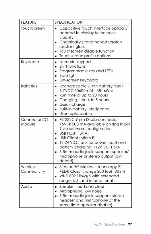
Ap D Specifications 97
FEATURE SPECIFICATIONTouchscreen � Capacitive touch interface optically
bonded to display to increase visibility
� Chemically strengthened scratch resistant glass
� Touchscreen disable function � Touchscreen profile options
Keyboard � Numeric keypad � Shift functions � Programmable key and LEDs � Backlight � On-screen keyboard
Batteries � Rechargeable Li-Ion battery pack, 3.7VDC 10600mAh, 38.16Whr
� Run time of up to 20 hours � Charging time 4 to 5 hours � Quick charge � Built-in battery intelligence � User-replaceable
Connector I/O Module
� RS-232C 9-pin D-sub connector, +5V @ 500 mA available on ring in pin 9 via software configuration
� USB Host (Full A) � USB Client (Micro B) � 12-24 VDC jack for power input and
battery charging, +12V DC 1.67A � 3.5mm audio jack, supports speaker/
microphone or stereo output (pin detect).
Wireless Connectivity
� Bluetooth® wireless technology 2.1 +EDR Class 1, range 200 feet (30 m)
� Wi-Fi 802.11b/g/n with extended range. U.S. and international
Audio � Speaker, loud and clear � Microphone, low noise � 3.5mm audio jack, supports stereo
headset and microphone at the same time (speaker disable)

98 FC-500 Handheld Field Controller Owner’s Manual
FEATURE SPECIFICATIONLED Activity Indicators
� Red: power applied/charging status � Green: notification, application
programmable � Blue: function key locked or being
pressed, application programmableTemperature Specifications
� Operating Temperature: –22° to 140° F (–30° to 60° C). Note: Bluetooth® wireless technology is rated to –4° to 122° F (–20° to 50° C).
� Storage Temperature: –22° to 158° F (–30° to 70° C)
� Battery Charging Temperature: -4° to 140° F (-20° to 60° C)
Shock Resistance
� Withstands multiple 5 foot drops to concrete
Environmental Ratings and Standards
� IP68 rating, waterproof and dustproof � MIL-STD810G standard for water,
humidity, sand and dust, vibration, altitude, shock, low temperature, high temperature, temperature shock
Warranties � 24 months for FC-500 � 90 days for accessories � Extended service and maintenance
plans

Ap D Specifications 99
FEATURE SPECIFICATIONSoftware Included
� ActiveSync � Adobe Reader LE � Alarms � Calculator � Calendar � Contacts � E-Mail � File Explorer � Getting Started � Help � Internet Explorer � Internet Sharing � JSNav � Home screen, customizable with
selectable dashboard gadgets and program shortcuts
� On-Screen Keyboards, Mega Keys and Mega Keys Night
� Notes � Pictures & Videos � Remote Desktop Mobile � Search � Settings � Task Manager � Tasks � Windows Live � Windows Media � Windows Office Mobile
Note: Software on individual units may vary from this list.
Configurations � Standard with Wi-Fi, Bluetooth, 512MB RAM, 8GB Storage
� Geo with Standard features plus Camera and GPS/GNSS
� Geo with Standard features plus Camera, GPS/GNSS, and Cell US/North America and CE/EU Models

100 FC-500 Handheld Field Controller Owner’s Manual
FEATURE SPECIFICATIONCamera (Geo models)
� 5MP resolution � Autofocus � LED illuminator � Video capture � JPEG image format � Geotagging; embed and/or emboss
photo with date, time and GPS/GNSS position
� Flash and flashlight GPS/GNSS (Geo models)
� High-sensitivity GPS/GLONASS/SBAS receiver
� 2 to 5 meter typical accuracy � Post processing capability for
enhanced accuracy beyond 2 to 5 meters, BINR protocol
� Enhanced performance under heavy canopy
� Integrated real-time SBAS capability, support for WAAS, MSAS, EGNOS
� File format NMEA-0183 v2.3, default strings: GGA, GSA, GLL, GSV, RMC, VTG, ZDA, GPS
� 32 GNSS tracking channels � GPS/GNSS signal quality indicator on
Home screen � JSNav application
3G Data Modem (Geo model option)
� Integrated Cinterion PH8P module (Pentaband Worldwide), 800/850/ 900/1800/1900/2100 MHz data speeds, UMTS/HSPA+3GPP
� Does not support voice calls � Communicates on GSM-based
networks

Ap D Specifications 101
FEATURE SPECIFICATIONCertifications and Standards
� FCC Class B � CE Marking (applicable EMC, R&TTE,
and LVD directives) � Industry Canada � EN60950 Safety � Bluetooth SIG qualification � USB client � IP68 waterproof and dustproof � Designed to MIL-STD 810G
Standard Accessories
� Li-Ion battery � Hand strap (pre-installed) � USB micro client sync cable � AC wall charger with international
plug kit - Input: 100-240VAC, 50/60Hz, 0.5A - Output: 12VDC, 1.67A
� Capacitive stylus and tether � Screwdriver � Quick Start Guide � Owner’s Manual available at www.
TopconTotalCare.com � 2-year warranty
Optional Accessories
� Shoulder strap � Serial cable � Vehicle charging adaptor � Holster case � Flip cover fitted case � 8GB micro SDHC memory card � Premium screen protectors
See your sales associate for more details on optional accessories.
Note: Specifications are subject to change without notice.

102 FC-500 Handheld Field Controller Owner’s Manual

Index

104 FC-500 Handheld Field Controller Owner’s Manual
Index
Symbols3G Data Modem 74
Connection Problems 77Data Account, Set up With Wireless Provider 74Gadget Color Indicators 31Maintenance of Your Modem 78RF Interference Issues 77Set up the Cell Modem 76SIM Card Installation 74Wireless Safety 77
AAccelerometer Calibration 39ActiveSync 41Anatomy of the Rugged Handheld 2Audio Features 25
Audio Jack 25Microphone 25Speaker 25
BBacklight 19Battery Pack 3, 5, 21
Charging 21Specifications 97Storage 80Warnings 90
Bluetooth Wireless Communication 44Microsoft Bluetooth Control Panel 45Serial Device (COM) Control Panel 47
CCamera 64
Button 12Embed GPS Information Into Files 67Embed User Note 67Emboss Picture Options 65, 66Flash Option 65

Index 105
Geotagging Pictures 65GPS Intermediate Driver Issues 56Photo and Video Library 71Specifications 100Videos 65
Care and Maintenance 80Cleaning 81Storage 80
Cautions 4, 21, 24, 37, 38, 74, 75, 81, 82, 86Certifications and Standards 91Cleaning 81Communicating With a Computer 41
ActiveSync 41Windows Mobile Device Center 41
Compass and Accelerometer Calibration 39, 57, 65Sensors Control Panel 40
Computer, Communicating With 41Connector Module 25
Cleaning 81Connector Protector 3
Connector Protector 3
DDashboard 29
Dashboard Gadgets 30Declaration of Conformity 94Display 16
Backlight 19Subdued Lighting (Tactical) Mode 38
Disabling 16
EEmbed GPS Information Into File 67Emboss Picture Options 66Equipment Warnings 91
FFavorites Bar 31
Application Shortcuts 31Flashlight 30Flash Option 65

106 FC-500 Handheld Field Controller Owner’s Manual
GGadgets 30Geo Model 54, 64Geotagging 65
Embed GPS Information Into File 67Emboss Picture Options 66
Getting Started Screen 42GPS/GNSS 54, 100
Accuracy 56Bluetooth COM Port Set Up 47Camera
Geotagging Pictures 65Compass 57Gadgets 30GPS Intermediate Driver 55, 56JSNav Application 57
Navigating to a Waypoint or Track 62Tracks 60Waypoints 59
Settings 55GPS Intermediate Driver 56
HHardware Features 12Hold to Zoom. See Zoom in on DisplayHome Screen 8
Button 12Dashboard 28, 29Dashboard Gadgets 30Status Icons 28, 29Tile Bar 28, 32Title Bar 28, 29Touchable Tiles 28, 32
JJSNav Application 57

Index 107
KKeyboard, On-screen 34Keypad 12
Action 12Backlight 15Programmable Function 12
LLanguage Installs 7Limitation of Liability 85
MMega Keys 34Microphone 25, 97Microsoft® Windows® Embedded Handheld 6.5.3 96
NNavigating Around Your FC-500 9
Touch Gestures 9Navigating to a Waypoint or Track 62
OOnline Help 42On-Screen Keyboard 33Operating System 96
Updates 7
PPower Management 22
Battery Life 22Battery Pack 21Charging Battery Packs 22
Power Off 37Product Warnings 90

108 FC-500 Handheld Field Controller Owner’s Manual
RRecycling the Rugged Handheld and Batteries 82Repairing 86
System Information 87Reset 37Restore 37Resume 36RS-232C Port 97
SScreen Protector 4SD Cards 24Sensors Control Panel 40SIM Card 3, 4, 74, 75Soft Keys (Touchable Tiles) 32Speaker 26, 97Specifications 96–103Start Menu 8Storing the Rugged Handheld and Battery Pack 80Subdued Lighting (Tactical) Mode 38Suspend 36Synchronization Software 41System Information 74, 87
TTactical Lighting Mode 38Temperature Specifications 98Tile Bar 28, 32Title Bar 28, 29Touchable Tiles (Soft Keys) 28, 32Touch Gestures 9Touchscreen
Disabling and Enabling 16Display Backlight 19Modes 17Protecting the Touchscreen 80Settings 16Specifications 97
Touchscreen Modes 17Touchscreen Profile 17Tracks 60

Index 109
UUpdates, Operating System and Documentation 7USB Client 25, 101USB Host 25
WWarnings 90, 91Warranty 84–87
Exclusions 84Extended Warranties 86Limitation of Liability 85Remedy 85Repairs 86Services 86Warranty Exclusions 84Warranty Repairs 86
Waypoints 59Wi-Fi Wireless Networking 50
Connecting to a Wi-Fi Network 50Managing Connections 51Wi-Fi Dialog Box 52Wi-Fi Set up Screens 51
Windows Mobile Device Center 41Windows Start Menu 8
ZZoom in on Display 18


![Tether anthony[1]](https://img.dokumen.tips/doc/110x75/557c7d36d8b42a494c8b5161/tether-anthony1.jpg)

