Embed Size (px)
Citation preview


Our brand
2
POWERDYNAMICPASSIONCOMMITMENTCREATIVITY
A strong brand for strong products:
The ENERGOLINE brand represents our product portfolio of INDUSTRIAL SWITCHGEAR SYSTEMS. Our products are characterized by a high degree of safety, flexibility and cost-efficiency. Type-tested components, compatible products and standardized interfaces are the special features of our ENERGOLINE family.
The ENERGOLINE brand is emblematic of power, dynamics and strength – properties that our products demonstrate on a daily basis in countless applications.
8PU Premium
Premium quality for all low voltage applications
MV Energy
The energizer of medium voltage up to 17,5kV
ENERGOLINE is more than just quality products “made in Germany”. ENERGOLINE is, first and foremost, our employees, and their dedication, creativity and passion.

Introducing our products
The INDUSTRIAL SWITCHGEAR SYSTEM
provides a well-engineered standard product with a type-tested, factory-assembled, air-insulated medium voltage switchgear that can be flexibly used in the networks of public utility companies, public-sector energy companies and industrial companies. It can be used universally as a ring cable switchgear system as well as for complex power distribution.
The MV Energy medium voltage switchgear can be employed wherever medium voltage power has to be distributed safely and economically. It is able to carry out every switching, separation, distribution and control function required of a switchgear system.
Proven design principles, the latest in innovation, flexible modu-lar solutions and continuous type and arc fault testing guarantee appropriate use and the highest degree of reliability and cost-ef-fectiveness.
With its wide spectrum of slide-in and fixed-mounted options, the system can be used for all types of applications in the areas of energy supply, energy distribution, power stations, process indus-tries and infrastructure.
Series:
» R12 up to 12 kV 3.150 A 40 kA
» R17,5 up to 17,5 kV 3.150 A 40 kA
Our portfolio includes various designs that can easily be combined with one another:
» Vacuum circuit breakers using fixed-mounted and slide-in tech-nology» Vacuum contactor using fixed-mounted and slide-in technology » Switch disconnectors using fixed-mounted technology » Measuring fields
Today, resistance to arc faults is an important and, in many appli-cations, an imperative requirement of modern INDUSTRIAL SWITCHGEAR SYSTEM.
All of our switch cabinets are certified in accordance with IEC 62271-200 and fulfil, without exception, the criteria required by arc fault testing. The medium voltage switchgear MV Energy is IAC qualified which serves as proof that it is safe for both personnel and the equipment itself.
The switch cabinets are furnished with all of the equipment, lo-cking mechanisms and accessories necessary to ensure a high level of personal and system safety and reliability.
Safely reliable Your advantages at a glance:
» Air-insulated medium voltage switchgear, metal-clad, indoor installation
» More economical and higher fl exibility thanks to the modular system
» Type-tested in accordance with all major international standards
» Various design options that can be fl exibly combined
» Single or dual busbar system
» The highest degree in personal and system protection through arc fault testing, IAC AFRL 40 kA, 1s
» Partition class PM: metal partitioning between all devices, busbar and cable compartments
» High-quality measuring, control and protection systems ensure reliable operation that can be designed to meet technical and customer requirements
» Use of communication-specifi c components
» Can be optionally equipped with a certifi ed pressure release duct
» Routine factory testing in accordance with VDE/EN/IEC standards and specifi c customer requirements
3

Equipment and switchgear accessoriesDetail drawing of an incoming or outgoing panelThe medium voltage switchgear MV Energy can be fitted with a large ran-
ge of devices for switching, controlling, measuring and protecting.
Slide-in vacuum circuit breakersThe circuit breakers are mounted on the slide-ins and can be with-drawn. The procedure can be carried out with a closed door. Control and signal leads are connected to a low voltage compartment by a plug.
» Switching units preferably from ABB, Siemens and TAVRIDA Other manufacturers available upon request.
Slide-in vacuum contactors The vacuum contactor is mounted on the slide-in and can be withdrawn. The procedure can be carried out with a closed door. Control and signal leads are connected to the low voltage compartment by a plug. » Switching units preferably from ABB and Siemens
Switch disconnectors The permanently installed switch disconnector is designed for switching and protecting the ring line or transformers (in connection with HV fuse links for short circuit protection) or for current-free switching. Each unit can be designed with an earthing switch with a making capacity for grounding wires.» Switching units preferably from ABB and TAVRIDA
Current transformersCast resin contactor transformers are used for feeding the measu-ring and protection devices. Their thin design enables switch cabinets up to B = 650 mm.» Preferably from ABB, ELEQ, Ritz or according to customer requirements
Voltage convertersThe single-pole voltage converters are permanently installed or can be mounted on a slide-in trolley. Their thin design enables switch cabinets up to B = 650 mm.» Preferably from ABB, ELEQ, Ritz or in accordance to customer requi-rements
Earthing switchesEvery incoming feeder cubicle and outgoing feeder panel can be deliver-ed with a quick earth electrode for grounding wires and busbars that is protected against switch-on. These can be operated using a manually operated or motor driven bevel-gear that is either mechanically or elec-tronically locked » to the circuit breaker slide-in unit and/or » to the door of the cable terminal compartment.The position of the earthing switch can be checked via a window in the door.
Surge arresters There is sufficient room in the cable terminal compartment for surge protection.
Cable terminalDepending on the current, up to 8 cables per phase can be connected. The power cable is fed from below, or, upon request, from above as well. Optional accessories» Transport trolley for circuit breakers» Lifting equipment for the shutters» Crank for circuit breaker slide-in unit» Switching lever for earthing switch » Double bit keys, or keys for a profile cylinder » Installation material/unit screw connection/crank for mech. release
Provided by the customer: Foundation-levelling rails/frames
1
2
3
4
5
6
7
8
9
10
11
12
13
14
15
Side frame
Low voltage compartment
Circuit breaker compartment
Metal shutter
Vacuum circuit breaker
Swing handle lock
Door handle
Window
Cable terminal compartment
Earthing switch
Current transformer
Contact isolator
Busbars
Insulating bushing
Pressure release fl ap
Optional: voltage converter and surge arrester
Reliability produces satisfaction
4

Functional compartmentsEvery unit consists of four functional compartments:
» Busbar compartment (1),
» Cable terminal compartment (2),
» Switchgear compartment (3),
» and Low voltage compartment (4).
The functional compartments are separated both physically and electrically from one another by partitioning and isolating distances. This allows the functional compartments or units to remain live even though other functional compartments are open.
Busbar compartment The busbar compartment contains the busbar system which is connected to the upper fixed contacts of the switchgears via branch connections. The busbars are made of electrolyte cop-per. The busbar compartment of each unit is separated from its neighbouring unit.
Cable terminal compartment In the cable terminal compartment, the power cable is connec-ted to the lower fixed contacts of the switchgears (e.g. circuit breakers) via a branch connection system. The branch connec-tions are made of electrolyte copper. The cable terminal com-partment is designed for the optional installation of a three-pole earthing switch, three surge arresters and three current/volta-ge transformers. The cable terminal compartment is closed off with a floor panel. Depending on the rated voltage, size of the unit and the cross-section of the cable, up to eight 1 or 3 pole cables can be connected.
Switchgear compartmentThe switchgear compartment contains the insulating bushings with the permanent contacts for connecting the switchgears to the busbars and the terminal compartment. The bushings are made of cast resin and are shielded by the metal shutters. The metal shutters function automatically during the movement of the switchgears from the deployed position to the service po-sition and vice versa.
Low voltage compartment The low voltage compartment contains all of the control and protection devices and the wiring of the components.
Pressure release ductOur fault arc resistant switchgear systems normally have a pres-sure release duct to discharge gases in the unlikely event of an arc fault. This is located over the switch cabinets and is installed along the entire system
MV EnergyAccess from the front
MV EnergyAccess from the front
3
2
1
4
XX
1 1
4
1
3
4
XX
Mechanical layout
Provided by the customer: Foundation-levelling rails/frames
5
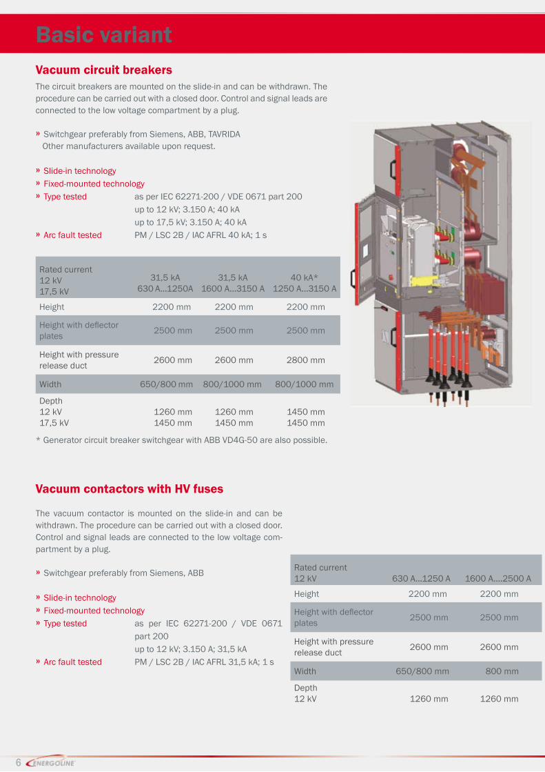
Basic variantVacuum circuit breakersThe circuit breakers are mounted on the slide-in and can be withdrawn. The procedure can be carried out with a closed door. Control and signal leads are connected to the low voltage compartment by a plug.
» Switchgear preferably from Siemens, ABB, TAVRIDA Other manufacturers available upon request.
» Slide-in technology» Fixed-mounted technology » Type tested as per IEC 62271-200 / VDE 0671 part 200 up to 12 kV; 3.150 A; 40 kA up to 17,5 kV; 3.150 A; 40 kA » Arc fault tested PM / LSC 2B / IAC AFRL 40 kA; 1 s
The vacuum contactor is mounted on the slide-in and can be withdrawn. The procedure can be carried out with a closed door. Control and signal leads are connected to the low voltage com-partment by a plug.
» Switchgear preferably from Siemens, ABB
» Slide-in technology» Fixed-mounted technology » Type tested as per IEC 62271-200 / VDE 0671 part 200 up to 12 kV; 3.150 A; 31,5 kA » Arc fault tested PM / LSC 2B / IAC AFRL 31,5 kA; 1 s
Rated current12 kV 630 A...1250 A 1600 A....2500 A
Height 2200 mm 2200 mm
Height with defl ector plates 2500 mm 2500 mm
Height with pressure release duct 2600 mm 2600 mm
Width 650/800 mm 800 mm
Depth12 kV 1260 mm 1260 mm
Rated current12 kV17,5 kV
31,5 kA630 A...1250A
31,5 kA1600 A...3150 A
40 kA*1250 A...3150 A
Height 2200 mm 2200 mm 2200 mm
Height with defl ector plates 2500 mm 2500 mm 2500 mm
Height with pressure release duct 2600 mm 2600 mm 2800 mm
Width 650/800 mm 800/1000 mm 800/1000 mm
Depth12 kV17,5 kV
1260 mm1450 mm
1260 mm1450 mm
1450 mm1450 mm
Vacuum contactors with HV fuses
6
* Generator circuit breaker switchgear with ABB VD4G-50 are also possible.

Basic variantLoad break switchThe fixed-mounted switch disconnector is made for switching and protecting the ring line or transformers (in connection with HV fuse links for short circuit protection) or for current-free switching. Each unit can be designed with an earthing switch with a making capacity for grounding wires.
» Switchgear preferably from ABB, Areva
» Fixed-mounted technology » Type tested as per IEC 62271-200 / VDE 0671 part 200 up to 17,5 kV; 2.500 A; 25 kA » Arc fault tested PM / LSC 2A / IAC AFRL 31,5 kA; 1 s
Options» Load break switch as ring line / branch connection» Load break switch with HV fuse as transformer or outgoing feeder » Separate earthing switch or in combination with load break switch
Measuring fi eld
» Slide-in technology» Fixed-mounted technology » Type tested as per IEC 62271-200 / VDE 0671 part 200 up to 17,5 kV; 3.150 A; 40 kA; 1 s» Arc fault tested PM / LSC 2A / IAC AFRL 40 kA; 1 s
Options» Fuse-voltage converter combination using slide-in or fixed-mounted technology » Current transformer using fixed-mounted technology
Rated current12 kV17,5 kV
630 A...1250 A630 A...1250 A
1600 A....3150 A1600 A....3150 A
Height 2200 mm 2200 mm
Height with defl ector plates 2500 mm 2500 mm
Height with pressure release duct 2600 mm 2600 mm
Width 650/800 mm 800/1000 mm
Depth12 kV17,5 kV
1260 mm1450 mm
1260 mm1450 mm
7
Rated current12 kV17,5 kV
31,5 kA630 A...1250 A
31,5 kA1600 A....3150 A
40 kA1250 A...3150 A
Height 2200 mm 2200 mm 2200 mm
Height with defl ec-tor plates 2500 mm 2500 mm 2500 mm
Height with pressu-re release duct 2600 mm 2600 mm 2800 mm
Width 650/800 mm 800 mm 800 mm
Depth12 kV17,5 kV
1260 mm1450 mm
1260 mm1450 mm
1450 mm1450 mm

Basic variantCombi-cabinet
» Fixed-mounted technology » Type tested as per IEC 62271-200 / VDE 0671 part 200 up to 24 kV; 3.150 A; 31,5 kA » Arc fault tested PM / LSC 2A / IAC AFRL 31,5 kA; 1 s
Variants» Vacuum circuit breaker» Vacuum contactor fuse combinations » Voltage converter measurement slide-ins» Current transformer» Measuring sets
Dual busbar systems
» Fixed-mounted technology » Type tested as per IEC 62271-200 / VDE 0671 Teil 200 up to 12 kV; 2500 A; 31,5 kA» Native current 4000 A; 40,0 kA (as per VDE 0101)
Rated current12kV 630 A...1250 A 1600 A....3150 A
Height 2200 mm 2200 mm
Height with defl ector plates 2500 mm 2500 mm
Height with pressure release duct 2600 mm 2600 mm
Width 650/800 mm 800/1000 mm
Depth12kV 1260 mm 1260 mm
Rated current12kV 630 A...1250 A 1600 A....3150 A
Height 3000 mm 3000 mm
Height with defl ector plates 3400 mm 3400 mm
Height with pressure release duct 3600 mm 3600 mm
Width 750 mm 1000 mm
Depth12kV 1700 mm 2000 mm
Variants» Vacuum circuit breaker» Vacuum contactor fuse combinations » Voltage converter measurement slide-ins» Current transformer» Measuring sets
1700 2000
3000
8

The switch cabinets are provided with all of the necessary locking mechanisms to allow for the highest level of reliability and safety for personnel and equipment.
Standard safety features» The circuit breakers can only be switched in operating or discon-nected position.» The slide-in can only be moved between the operating and the disconnected position when the circuit breaker is switched off.Optional safety features» The slide-in can only be switched from the disconnected to the operating position when the control cable is plugged in.» The control cable can only be unplugged in the disconnected position.» The slide-in can only be switched to operating position if the earthing switch is turned off.» The door of the switchgear compartment can only be opened if the slide-in is in the disconnected position. The shutters are located in front of the contact isolators. » The door of the cable terminal compartment can only be opened if the earthing switch is turned on. The lock can be unlocked using a reset bolt.» The shutter can be locked.» The doors of the switchgear and cable terminal compartment can be locked (optionally with a double bit key or profile cylinder).» When in closed position, all of the doors can be locked with swing handle locks.
Mechanical locks Lock
Pressure release and pressure release duct All functional compartments, with the exception of the low voltage compartment, have their own pressure release on the roof of the switch cabinet. Any excess pressure within the switch cabinets as a result of an internal arc fault will open the corresponding pressu-re release flap. The following options are available depending on the current and ambient temperature:
» Smooth pressure release flap up to 1.250 A» Vented pressure release flap > 1.250 A,
These will open in the case of a fault and limit the rise in pressure in the switch cabinet.
Ceiling height > 3.000 mmFor stand alone units, gases are discharged through 300 mm diagonal deflector plates (on both sides and on the side). Vertical deflector plates on the side of the switchgear conduct the gases out of the switch cabinet when wall mounted.
Ceiling height < 3.000 mmThe pressure release duct leads outside or to subordinate rooms not accessible by the public (e.g. transformer room) and is closed with a pressure release flap. The optional pressure release duct runs the entire length of the switchgear.
Pressure release fl aps / pressure release duct in accordance with IEC 62271-200
Diagonal discharge plates for stand alone units
High operational safety
9

The medium voltage switchgear MV Energy a component of the ENERGOLINE product range, is a complete, type-tested, air insulated switchgear system whose physical properties, have been verified in operating and fault situations in accredited testing institutes in ac-cordance with IEC 62271-200 requirements.
Type testing» Proof of compliance with high temperature limit » Proof of impact resistance and short-circuit strength » Proof of the AC voltage testing of the main and auxiliary circuits » Proof of short circuit making and breaking capacity of the switchgears » Proof of the making capacity of the earthing switch » Proof of mechanical functionality » Proof of IP protection class
» Testing under arc fault conditions
Accessibility and operational availability
The set-up of the switchgear systems is in accordance with the LSC2B-PM classification as per IEC 62271-200: All compartments can be opened without tools. Locks allow access only when the corresponding medium voltage parts are turned off and are grounded. Busbar, cable and switchgear compartments are partitioned. Other functional com-partments and units can remain live even if the main circuit compart-ment is open.
Maximum protection for equipment and personnel
Certifi ed safety
Routine factory testing before delivery As a general rule, every switch cabinet undergoes routing factory testing before it is delivered:» Inspection of the switchgears and wiring, » Conformity with the approved documentation ,» Electrical functional testing, » Insulation testing,» Mechanical switching run,» Resistance measurement of the main circuit.In addition of the structural arc fault protection, we also offer solutions for active arc fault protection from all con-ventional system providers.
arc fault test of a medium voltage switchgear with pressure release duct
Partition classes PM Metal cladding
PI Covered with insulating material Operational availability LSC1 The busbars and thus the entire switchgear system must be switched off.
LSC2A The busbars and adjacent switch cabinets can remain live.
LSC2B Other switch cabinets, the busbars and all cable compartments can remain in operation
IAC classifi cation Accessibility
A Metal encapsulated switchgear that can only be accessed by electrical professionalsB Metal encapsulated switchgear with unrestricted accessibility, also for the public.
C Systems mounted on a mast.
FRL Access from the front (F = front), from the side (L = lateral) and from behind (R = rear)
MV Energy IAC A FRL 40 kA, 1sOur switchgear offers the best personal protection thanks to the verifi able arc fault quali-fi cation IAC A FRL up to 40 kA and one second arc duration.
Principles in accordance with IEC 62271-200 / VDE 0671-200:2008-03
10

11
Technical data
Standards and directives
Switchgear
Devices
Medium voltage switchgear systems – Part 200: Metal encapsulated AC switchgear systems
for rated voltages above 1 kV and up to and including 52 kV (IEC 17C/421/CD:2007)
Earthing switches
Circuit breakers
High voltage AC current contactors
Switch disconnectors
DIN IEC 62271-200; VDE 0671-200:2008-03
DIN IEC 62271-102/A1; (VDE 0671-102/A1:2009-02)
IEC 62271-100; EN 62271-100
IEC 60470; EN 60470:
IEC 60265-1; DIN EN 60265-1
Electricalparameters
Rated voltages Rated voltage Ur
Rated power frequency withstand voltage Ud
Rated lightning impulse withstand voltage Up
Rated frequency
12 kV / 17,5 kV 28 kV / 38 kV75 kV /95 kV50/60 Hz
Rated currents Rated breaking capacity ISC
Rated peak current Ip
Rated short-time withstand current Ik
Rated duration of short-time withstand current tk
12 kV bis 40 kA 17,5 kV bis 40 kAup to 80 kA / 63 kAup to 31,5 kA; 40 kA / 25 kA
up to 3 sRated currents Busbars
Branch connectionsup to 3.150 A /2.500 A630 A, 1.250 A, 1.600 A,2.000 A, 2.500 A
Mechanical parameters
Cabinet measurements
Cabinets and support framesHeightWidthDepth
2.200 mm 1)
650, 800, 1.000 mm1.260, 1.450 mm 2)
Customized adjustments possible
Protection classes
In accordance with IEC 60529, EN 60529 IP 20 to IP 4X
Surface protection
Coating as per DIN 43656, Standard coating thickness Support frames, sendzimir galvanized Encasement
Epoxy polyester powder65 µmRAL 7035(upon request)RAL 7035( upon request )Special colours and double coating available
Ambient conditions
Rated properties
Ambient temperatureRelative humidityMaximum elevation
-5 ... +40 °C95 %1.000 m mean sea level
1) with defl ector plates +300 mm with pressure release duct + 400 mm (31,5 kV) and + 600 mm (40 kA)2) for doors and rearplate 2x30 mm = 60 mm

w w w . f e a g - s g h . d e
FEAG Sangerhausen GmbH
Gewerbegebiet "Helme-Park"
Stiftsweg 1
06526 Sangerhausen
Fon.: +49 (0)3464/558-30
Fax: +49 (0)3464/558-410
E-Mail [email protected]
Directions
w w w . e n e r g o l i n e . d e
Note:We reserve the right to make technical changes or modify the contents of this document without prior notice.With regard to purchase orders, the agreed particulars shall prevail. FEAG Sangerhausen GmbH does not accept any responsibility whatsoever for potential errors or possible lack of information in this document.