Embed Size (px)
Citation preview

Other LAN Technologies

2LAN Standards
802 Working Groups
– 802.3 Ethernet LANs
– 802.5 Token-Ring Networks
– 802.11 Radio LANs
– 802.12 100VG-AnyLAN

3802.5 Token-Ring Network Standard
Championed by IBM– Official IEEE and OSI standard, but most vendors
follow IBM extensions to the standard
More reliable than 802.3 Ethernet LANs
More complex and therefore more expensive
Lower market share than Ethernet LANs– Mostly in firms with large IBM mainframe networks
– Tightly integrated into SNA
Read a tutorial in token-ring networks

4Ring Topology in Token-Ring Networks
StationB
StationA
StationE
StationD
StationCFrame
Frame
Ring
Station B only receives frames from Station A and only transmits frames to Station C
Ring

5Problem with Rings
If the ring breaks, LAN stops– Signals must go all the way around the ring, back
to the sender
– This becomes impossible

6Use a Double Ring
One is unused in normal operation If there is a break, the ring is wrapped
– Still a ring
Normal Wrapped

7UTP and STP Wiring
UnshieldedTwisted Pair
(UTP)
ShieldedTwisted Pair
(STP)
TwistedPair
TwistedPair
Shielding Around Pair
Outer ShieldAround Bundle
Plastic Cover (Non-Shielding)TwistedPair
TwistedPair

8STP vs. UTP
STP– Little interference
– Thick: difficult to install
– Expensive
UTP– Thin: easy to install
– Inexpensive
– Interference is rarely a practical problem
– Does the job at a reasonable price, so dominates

9Access Units in a Ring
Access Unit Access Unit
Access Unit Access Unit
STP link betweenAccess Units
STP linkfrom Stationto Access
UnitStations
Station
UTP Linkfrom Stationto Access
Unit

10
NIC NICNIC
Within the Access Unit
The ring is retained Powered-up NICs added automatically Powered-off NICs bypassed automatically
Ring
MissingNIC
Bypassed Node

11Token Passing in 802.5 Token-Ring Networks
Token
StationB
Station B may only transmit when it receives a special frame called a token.

12Ethernet (802.3) vs Token-Ring (802.5) Physical Layer
– Ethernet primarily uses UTP wiring
– Token-Ring Networks primarily use shielded twisted pair (STP) wiring
Topology (Layout) of the Wiring
– Ethernet always uses bus (broadcast) topology
– Token-Ring always uses a ring topology (connectivity)
Access Control
– (Control of When Stations May Transmit)
– Ethernet always uses CSMA/CD
– Token-Ring always uses token passing

13Ethernet (802.3) vs Token-Ring (802.5) Speed
– Ethernet primarily 10 Mbps (moving to 100 Mbps and gigabit speeds)
– Token-Ring Networks usually at 16 Mbps
– TRNs can get closer to full capacity because token passing is more efficient than CSMA/CD at high traffic loads
– Priority levels for real-time traffic (video teleconferencing, etc.)
Cost– TRN is more complex, so NICs cost much more
– TRN has low market share; low vendor competition adds to high NIC costs
– Most firms do not find the benefits of TRNs to outweigh the costs

14Shared Media LANs
Ethernet (802.3) and Token-Ring Networks (802.5) are Shared Media LANs
– Only one station may transmit at any moment.
– Every station hears every transmission
– Stations must wait their turn to transmit

15Congestion and Latency in Shared Media LANs
Transmission
Shared Media LAN
Station Bis Transmitting
But MustStop Soon
Station AMust Wait
to Transmit
Station CMust Wait
to Transmit

16Congestion and Latency
As the number of stations on a shared media LAN increases...– Traffic increases, so
– Stations must wait longer to transmit
– Latency (delay) increases
– This is called congestion
At 200-300 stations, a 10 Mbps (4-16 Mbps) shared media LAN becomes saturated

17100 Mbps LANs
Reducing Congestion
– One way to decrease congestion is to increase LAN speed from 10 Mbps to 100 Mbps or higher
– Each transmission will be briefer, because it can be transmitted faster
– Therefore more stations can share the LAN before saturation occurs
– Only postpones the problem

18FDDI Network
FDDI Ring

19FDDI FDDI
– Fiber distributed data interface
– Token-ring technology (but incompatible with 802.5)
– 100 Mbps
– Mature (1987)
– 200 km maximum diameter: popular for connecting LANs to local internets, not to connect desktops.
– Priority levels for real-time traffic (voice, video)
– Expensive NICs and other equipment
– Read a tutorial in FDDI

20802.12 100VG-AnyLAN
100 Mbps
Demand Priority Access Method– Station sends high- or low-priority requests
– All high-priority requests on all repeaters served first
– Good for real-time applications
Hubs (repeaters) organized as a Tree– One is the master repeater
Not achieving market acceptance

21802.12 100VG-AnyLAN Hub Hierarchy
Repeater A
Repeater B Repeater C
Repeater D Repeater E
MasterRepeater
Station 1Station 1 Station 2Station 2
High-Priority Request Low-Priority Request
FirstLevelRepeater
SecondLevelRepeaters
ThirdLevelRepeaters

22100Base-X
100 Mbps
Uses Normal 802.3 MAC Layer Frame
Family of Standards– 100Base-TX uses Cat 5 wiring (most popular to
desk)
– 100Base-T4 uses Cat 3 and Cat 4 wiring
– 100Base-FX uses optical fiber

23100Base-TX
Many install 100Base-TX instead of 10Base-T Today
Requires 100 Mbps hubs instead of 10 Mbps
Requires 100 Mbps NICs instead of 10 Mbps– Some hubs can also serve 10Base-T NICs, so not
all stations have to be upgraded at once
Uses Category 5 wiring, making upgrading easy

24Upgrading from 10Base-T to 100Base-T
Need New Hub– All 100Base-TX is expensive
– Often many 10Base-T hubs for client PCs
– A few 100Base-TX hubs for servers
Need New NICs– Only in stations with 100Base-T NICs
Retain Old Wiring– If Cat 5
– Avoids a major expense

25Ethernet 100Base-TX Network
100Base-TX Hub
Station A Station B Station C
100 mSegmentMaximum
100 mSegmentMaximum
~50 maximum
- 5 UTP wiring- NICs are replaced
100Base-TX Hub

26Ethernet 100Base-TX Network The most popular 100Base-X standard, runs over
existing 5 UTP wire of 10Base-T
Only two segments, length ~200m
Can mix 10 Base-T and 100Base-T stations/NICs with hubs that take both types
Use the same 802.3 MAC standard of 10 Base-T
Market has chosen Ethernet 100Base-TX for desktop connection over FDDI and 100VG-AnyLAN
Read classic tutorial on Fast Ethernet

271000Base-X (Gigabit Ethernet)
1000 Mbps
Usually used to link 100Base-X hubs
1000Base-X Hub
100Base-T Hubs

281000Base-X
Family of Standards (802.3z)
1000Base-LX– Long-wave (lower frequency) laser
– 550 meters on multimode optical fiber
– 3 km on single mode fiber
1000Base-SX– Short-wave ( higher frequency) laser
– 300 meters on 62.5 micron multimode fiber

29
Full Duplex Ethernet
CSMA/CD is half duplex– Only one station may transmit at a time
– Others must wait
– Because transmission system is shared
If station or hub connects directly to a hub,– The access line is not shared
– Some 100Base-X and 1000Base-X hubs and NICs support full duplex operation
– Disable CSMA/CD
– 802.3x standard

30Shared media LANs
Limits to Shared Media LANs
– FDDI, 100Base-X, 100VG-AnyLAN all shared media LANs
Only one station can transmit at a time, causing latency
Every station hears every message, so as the number of stations grow, the LAN saturates
– 100 Mbps speed only delays saturation
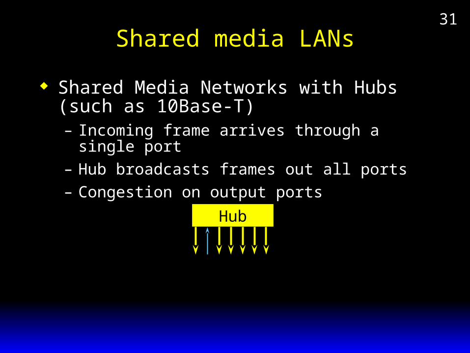
31Shared media LANs
Shared Media Networks with Hubs (such as 10Base-T)– Incoming frame arrives through a single port
– Hub broadcasts frames out all ports
– Congestion on output ports
Hub

32Switched LANs
In a switched network– Incoming frame arrives on a single port
– Frame sent out again only on a single port--the one leading to the receiver
– No congestion on other ports
Switch

33Switch
Switch
StationA
StationB
StationC
StationD
Connection 1A-C
Connection 1A-C
Connection 2B-D
Connection 2B-D
With a switch, multiple stations may transmit simultaneously: no congestion as traffic grows.

34Switching in Perspective
Switching is the wave of the future for LANs
– Congestion does not increase as the number of stations grows
However,
– Today, however, switches are still more expensive than 10Base-T or 100Base-X hubs
Read CISCO white paper
– discount the sales talk
– see 3COM images of switches.

35Switch connections paths called connections must be pre-defined
between stations
a fixed logical data link (logical connection) is established between stations before transmission even begins
during the transmission, all traffic between the stations must pass over that data link
unless a data link has been pre-established, two stations may not communicate at all
only OSI Layer 2 (Data Link Layer) protocols are needed

36Ethernet Switches Ethernet Hubs are Half Duplex
Most Ethernet Switches are Full Duplex– No collisions are possible
– So two stations can both transmit to each other at the same time (full duplex operation)
– Requires full duplex switches
– Requires full duplex NICs
Lowest-cost LAN switches
Not standardized, so buyers tend to get locked into a single vendor

37ATM Switches
Asynchronous Transfer Mode
Will allow much higher speeds– 155 Mbps to a few Gbps
Can also be used for long-distance networking– A single solution for both needs
Quality of service guaranteed
Far more expensive than Ethernet LAN switches

38ATM Switches
standardized (others not yet)
scalable: as low as 1 Mbps to 2.4 Gbps– can start with relative slow speeds (cheaper)
– increase the speed as needs arise
– without changing protocol

39ATM and Ethernet
100Mbps and Gigabit Ethernet are outselling ATM for LAN usage
High-speed Ethernet is less expensive
Staff does not have to learn ATM technology
Sales of NICs - Ethernet, Token Ring and ATM.

40Wireless LAN
BroadcastSignal
TransceiverTransmitting
TransceiverReceiving
ClusterTransceiver
Receiving
Antenna
Hub Controller
Wireless LAN

41Typical 802.11 Wireless LAN Operation with Access Points
Switch
Client PCServer
Large Wired LAN
AccessPoint A
AccessPoint B
UTP Radio Link
HandoffIf mobile computermoves to another
access point,it switches serviceto that access point
Notebook
CSMA/CA+ACK
UTP

42 Typical 802.11 Wireless LAN Operation with Access Points
WirelessNotebook
NIC
Access Point
IndustryStandard
CoffeeCup
To EthernetSwitch
Antenna(Fan) PC Card
Connector

43Typical 802.11 Wireless LAN Operation with Access Points
D-LinkWirelessAccessPoint
Using Two Antennas Reduces Multipath Interference (See Ch. 3)

44
LinksysSwitchWith
Built-InWirelessAccess Point
Using Two Antennas Reduces Multipath Interference (See Ch. 3)
Typical 802.11 Wireless LAN Operation with Access Points

45Typical 802.11 Wireless LAN Operation with Access Points
The Wireless Station sends an 802.11 frame to a server via the access point
The access point is a bridge that converts the 802.11 frame into an 802.3 Ethernet frame and sends the frame to the server
MobileStation
AccessPoint
EthernetSwitch
Server
802.11Frame
802.3Frame

46Typical 802.11 Wireless LAN Operation with Access Points
The server responds, sending an 802.3 frame to the access point
The access point converts the 802.3 frame into an 802.11 frame and sends the frame to the mobile station.
MobileStation
AccessPoint
EthernetSwitch
Server
802.11Frame
802.3Frame

47802.11 Wireless LAN Speeds
802.11 2 Mbps (rare)2.4 GHz band (limited in
bandwidth)
802.11b 11 Mbps, 2.4 GHz3 channels/access point
802.11a 54 Mbps, 5 GHz (> bandwidth than 2.4 GHz)11 channels/access point
802.11g 54 Mbps, 2.4 GHzlimited bandwidth

48802.11 Broadcast Operation
The Wireless Stations and Access Points Broadcast their Signals.– Only one access point or wireless station may
transmit at any moment or signals will become scrambled.
CollisionAbout toOccurAccess
Point
WirelessStation
WirelessStation

49CSMA/CA + ACK in 802.11 Wireless LANs
CSMA/CA (Carrier Sense Multiple Access with Collision Avoidance)– Station or access point sender listens for traffic
If there is no traffic, can send if there has been no traffic for a specified amount of time
If the specified amount of time has not been met, must wait for the specified amount of time. Can then send if the line is still clear

50CSMA/CA + ACK in 802.11 Wireless LANs
CSMA/CA (Carrier Sense Multiple Access with Collision Avoidance)– Station or access point sender listens for traffic
If there is traffic, the sender must wait until traffic stops
The sender must then set a random timer and must wait while the timer is running
If there is no traffic when the station or access point finishes the wait, it may send

51CSMA/CA + ACK in 802.11 Wireless LANs
ACK (Acknowledgement)– Receiver immediately sends back an
acknowledgement; no waiting because ACKs have highest priority
– If sender does not receive the acknowledgement, retransmits using CSMA/CA

52Who Implements CSMA/CA+ACK?
Stations (when they send)
Access Points (when they send)
MobileStation
AccessPoint
802.11Frame
CSMA/CA+ACK
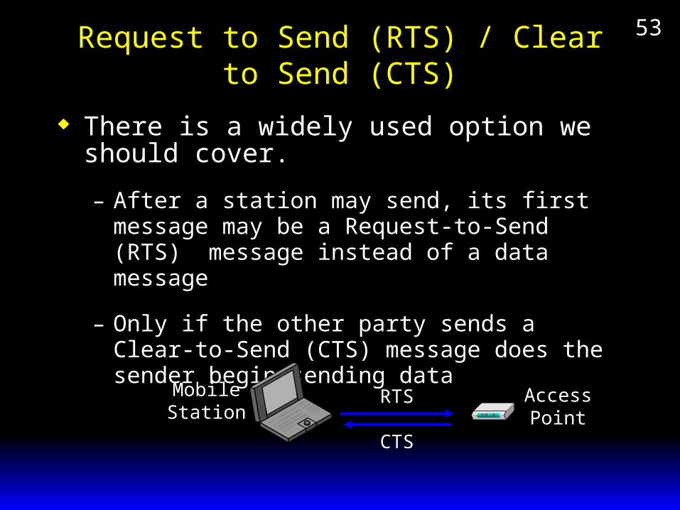
53Request to Send (RTS) / Clear to Send (CTS)
There is a widely used option we should cover.
– After a station may send, its first message may be a Request-to-Send (RTS) message instead of a data message
– Only if the other party sends a Clear-to-Send (CTS) message does the sender begin sending data
MobileStation
AccessPoint
RTS
CTS

54Ad Hoc 802.11 Networks
Ad Hoc Mode– There is no access point.– Stations broadcast to one another directly– Not scalable but can be useful for SOHO use– NICs automatically come up in ad hoc mode

55802.11 Security
Attackers can lurk outside your premises– In “war driving,” drive around sniffing out unprotected
wireless LANs
– In “drive by hacking,” eavesdrop on conversations or mount active attacks.
Site with 802.11 WLAN
OutsideAttacker

56802.11 Security
By default, security on 802.11 WLAN NICs and access points is turned off, making external attacks trivial
WLAN vendors offer Wired Equivalent Privacy (WEP), but this is weak and easily broken.
The 802.11 Working Group is working on a temporary replacement (TKIP) and longer-term security replacement, 802.11i
Even if corporate access points can be secured, many departments create unauthorized rogue access points that are seldom secured.