Embed Size (px)
Citation preview
EE 4272 Spring, 2003
Chapter 13. Local Area Network Technology
• LAN Applications
• LAN ArchitectureProtocol Architecture
Topologies
MAC
• Bus LANs
• Ring LANs
• Star LANs
• Extended LANs: Bridge
EE 4272 Spring, 2003
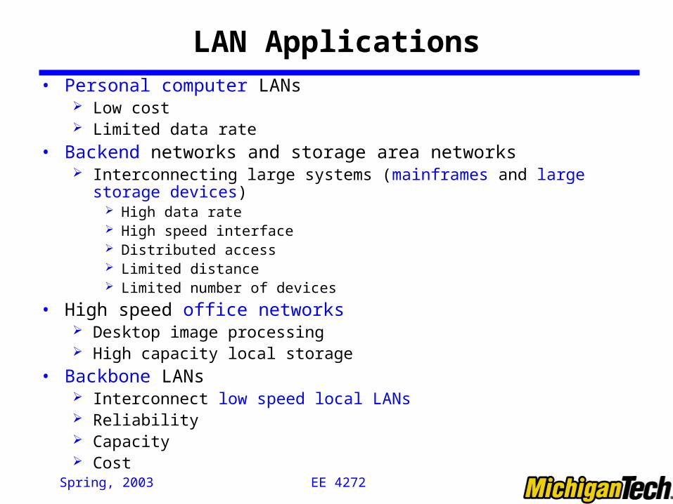
LAN Applications• Personal computer LANs
Low cost Limited data rate
• Backend networks and storage area networks Interconnecting large systems (mainframes and large storage devices)
High data rate High speed interface Distributed access Limited distance Limited number of devices
• High speed office networks Desktop image processing High capacity local storage
• Backbone LANs Interconnect low speed local LANs Reliability Capacity Cost
EE 4272 Spring, 2003
LAN Architecture
• Protocol architecture• Topologies• Media access control (MAC)• Logical Link Control
EE 4272 Spring, 2003
Protocol Architecture
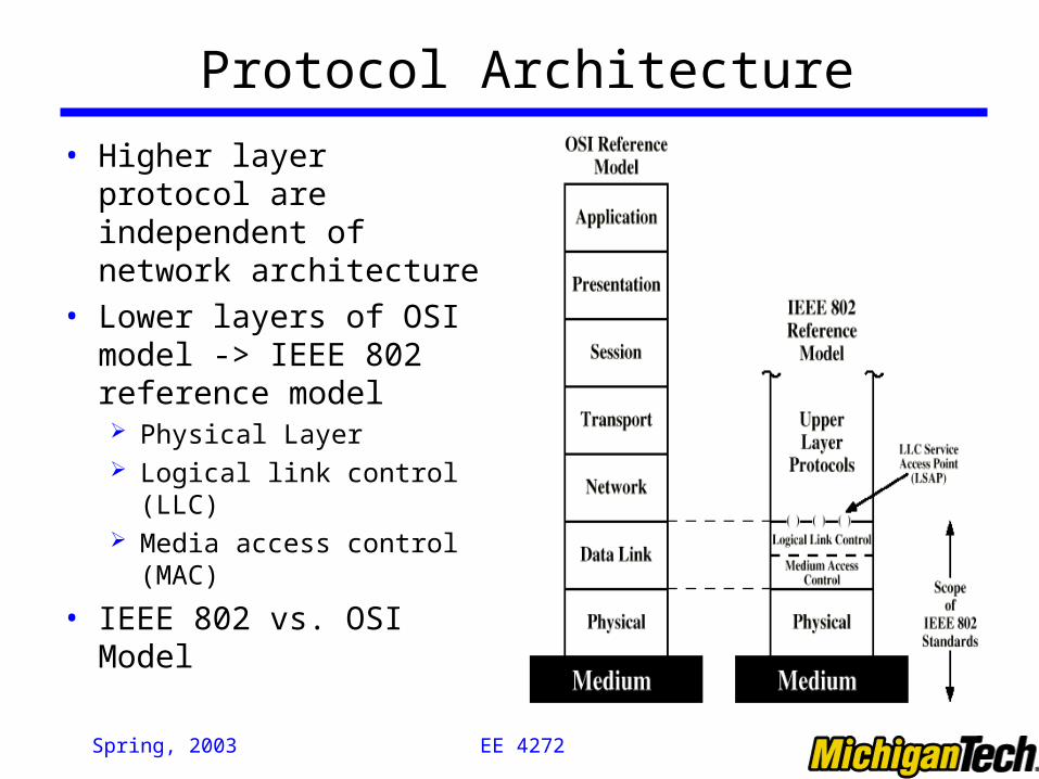
• Higher layer protocol are independent of network architecture
• Lower layers of OSI model -> IEEE 802 reference model Physical Layer Logical link control (LLC) Media access control (MAC)
• IEEE 802 vs. OSI Model
EE 4272 Spring, 2003
802 Layers
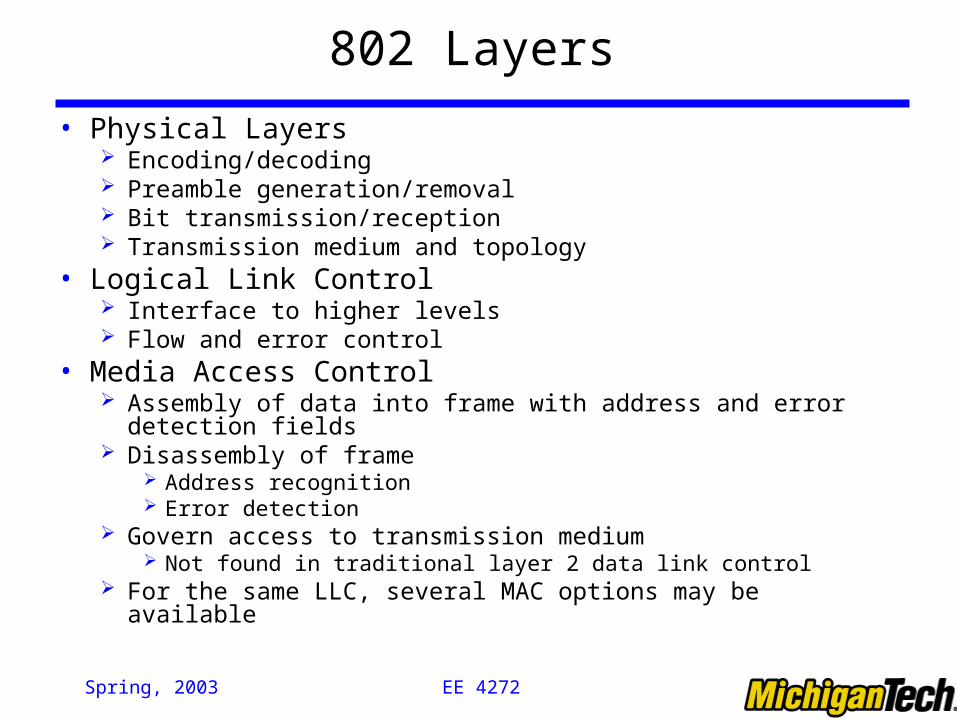
• Physical Layers Encoding/decoding Preamble generation/removal Bit transmission/reception Transmission medium and topology
• Logical Link Control Interface to higher levels Flow and error control
• Media Access Control Assembly of data into frame with address and error detection fields Disassembly of frame
Address recognition Error detection
Govern access to transmission medium Not found in traditional layer 2 data link control
For the same LLC, several MAC options may be available
EE 4272 Spring, 2003
LAN Topologies
EE 4272 Spring, 2003
Bus and Tree
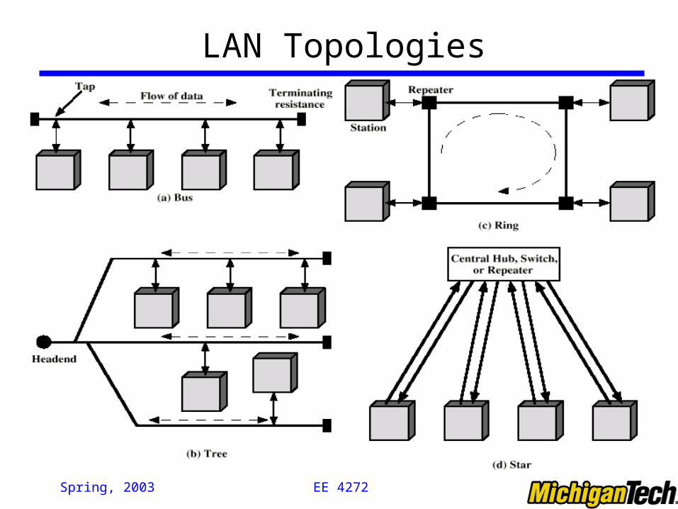
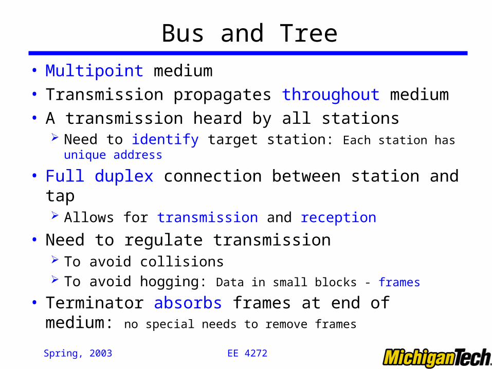
• Multipoint medium• Transmission propagates throughout medium • A transmission heard by all stations
Need to identify target station: Each station has unique address
• Full duplex connection between station and tap Allows for transmission and reception
• Need to regulate transmission To avoid collisions To avoid hogging: Data in small blocks - frames
• Terminator absorbs frames at end of medium: no special needs to remove frames
EE 4272 Spring, 2003
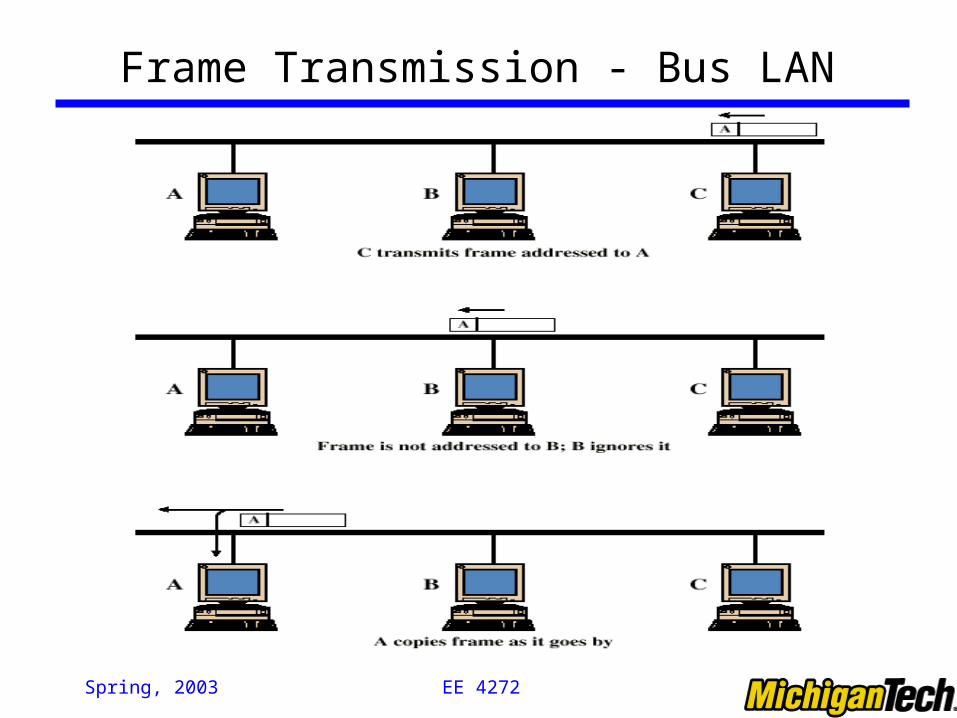
Frame Transmission - Bus LAN
EE 4272 Spring, 2003
Ring Topology
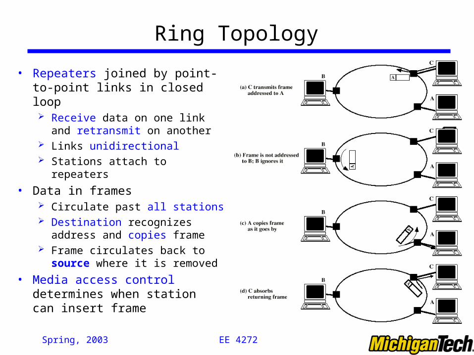
• Repeaters joined by point-to-point links in closed loop Receive data on one link and
retransmit on another Links unidirectional Stations attach to repeaters
• Data in frames Circulate past all stations Destination recognizes address and
copies frame Frame circulates back to source
where it is removed
• Media access control determines when station can insert frame
EE 4272 Spring, 2003
Star Topology
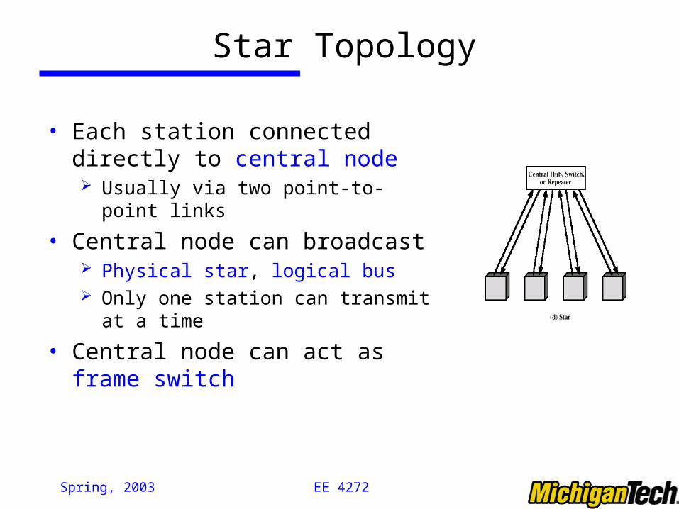
• Each station connected directly to central node Usually via two point-to-point links
• Central node can broadcast Physical star, logical bus Only one station can transmit at a time
• Central node can act as frame switch
EE 4272 Spring, 2003
Media Access Control
• Where Central
Greater control (e.g. priority, guaranteed capacity) Simple access logic at each station Avoids problems of co-ordination Single point of failure Potential bottleneck
Distributed
• How Synchronous: Specific capacity dedicated to connection (STDM/FDM)
Asynchronous: In response to demand (dynamic/statistic)
EE 4272 Spring, 2003
Asynchronous Systems• Round robin
Good if many stations have data to transmit over extended period
• Reservation: Good for stream traffic (similar to Synchronous TDM)
• Contention Good for bursty traffic All stations contend for time Distributed Simple to implement Efficient under moderate load Tend to collapse under heavy load
EE 4272 Spring, 2003
Technical Details of Bus LANs
• Signal balancing Signal must be strong enough to meet receiver’s minimum
signal strength requirements Give adequate signal-to-noise ration Not too strong that it overloads transmitter
Must satisfy signal balancing for all combinations of sending and receiving station on bus
Usual to divide network into small segments Link segments with amplifies or repeaters
EE 4272 Spring, 2003
BUS LAN: Transmission Media
• Twisted pair Not practical in shared bus at higher data rates
• Baseband coaxial cable: Used by Ethernet Uses digital signaling Manchester or Differential Manchester encoding Entire frequency spectrum of cable used Bi-directional Few kilometer range, 50 ohm cable, Ethernet (basis for 802.3) at
10Mbps
• Broadband coaxial cable (e.g., cable TV) Included in 802.3 specification but no longer made
• Optical fiber Expensive, Difficulty with availability
EE 4272 Spring, 2003
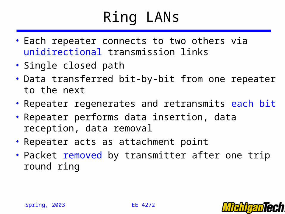
Ring LANs
• Each repeater connects to two others via unidirectional transmission links
• Single closed path• Data transferred bit-by-bit from one repeater to the next• Repeater regenerates and retransmits each bit• Repeater performs data insertion, data reception, data
removal• Repeater acts as attachment point• Packet removed by transmitter after one trip round ring
EE 4272 Spring, 2003
Ring Media
• Twisted pair• Baseband coaxial• Fiber optic• Not broadband coaxial
Would have to receive and transmit on multiple channels, asynchronously
EE 4272 Spring, 2003
Timing Jitter
• Clocking included with signal e.g. differential Manchester encoding Clock recovered by repeaters
To know when to sample signal and recover bits Use clocking for retransmission
Clock recovery deviates from mid-bit transmission randomly Noise, imperfections in circuitry
• Retransmission without distortion but with timing error• Solutions:
Repeater uses phase locked loop Minimize deviation from one bit to the next
Use buffer at one or more repeaters Hold a certain number of bits Expand and contract to keep bit length of ring constant

EE 4272 Spring, 2003
Potential Ring Problems
• Break in any link disables network (link failure)• Repeater failure disables network (node failure)• Installation of new repeater to attach new station
requires identification of two topologically adjacent repeaters
• Timing jitter• Method of removing circulating packets required
With backup in case of errors
• Mostly solved with star-ring architecture (e.g. FDDI)
EE 4272 Spring, 2003
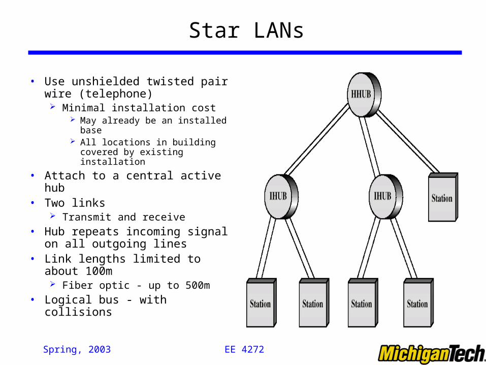
Star LANs
• Use unshielded twisted pair wire (telephone) Minimal installation cost
May already be an installed base All locations in building covered
by existing installation
• Attach to a central active hub• Two links
Transmit and receive
• Hub repeats incoming signal on all outgoing lines
• Link lengths limited to about 100m Fiber optic - up to 500m
• Logical bus - with collisions
EE 4272 Spring, 2003
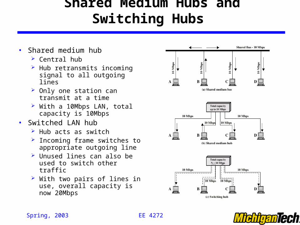
Shared Medium Hubs and Switching Hubs
• Shared medium hub Central hub Hub retransmits incoming signal
to all outgoing lines Only one station can transmit at a
time With a 10Mbps LAN, total
capacity is 10Mbps
• Switched LAN hub Hub acts as switch Incoming frame switches to
appropriate outgoing line Unused lines can also be used to
switch other traffic With two pairs of lines in use,
overall capacity is now 20Mbps
EE 4272 Spring, 2003
Switched Hubs
• No change to software or hardware of devices• Each device has dedicated capacity• Scales well• 2 Types
Store-and-forward switch Accept input, buffer it briefly, then output
Cut-through switch Take advantage of the destination address being at the start of the
frame Begin repeating incoming frame onto output line as soon as
address recognized May propagate some bad frames
EE 4272 Spring, 2003
Bridges• Ability to expand beyond single LAN• Provide interconnection to other LANs/WANs• Use Bridge or router• Bridge is simpler
Connects similar LANs Identical protocols for physical and link layers Minimal processing
• Router more general purpose Interconnect various LANs and WANs
• Ways of Interconnecting Networks: Repeater: By which multiple networks are interconnected at physical layer Bridge: By which multiple networks are interconnected at data link layer Router: By which multiple networks are interconnected at network layer Gateway: By which multiple networks are interconnected at higher layer
EE 4272 Spring, 2003
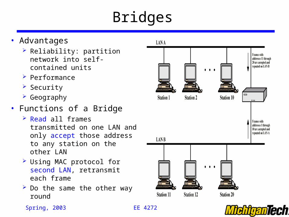
Bridges
• Advantages Reliability: partition network
into self-contained units Performance Security Geography
• Functions of a Bridge Read all frames transmitted on
one LAN and only accept those address to any station on the other LAN
Using MAC protocol for second LAN, retransmit each frame
Do the same the other way round
EE 4272 Spring, 2003
Bridge Design Aspects
• No modification to content/format of frame• No encapsulation• Exact bitwise copy of frame• Minimal buffering to meet peak demand• Contains routing and address intelligence
Must be able to tell which frames to pass May be more than one bridge to cross
• May connect more than two LANs• Bridging is transparent to stations
Appears to all stations on multiple LANs as if they are on one single LAN
EE 4272 Spring, 2003
Bridge Protocol Architecture
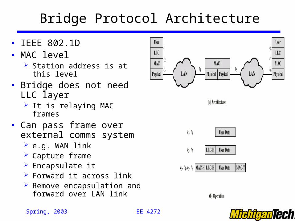
• IEEE 802.1D• MAC level
Station address is at this level
• Bridge does not need LLC layer It is relaying MAC frames
• Can pass frame over external comms system e.g. WAN link Capture frame Encapsulate it Forward it across link Remove encapsulation and
forward over LAN link
EE 4272 Spring, 2003
Fixed Routing
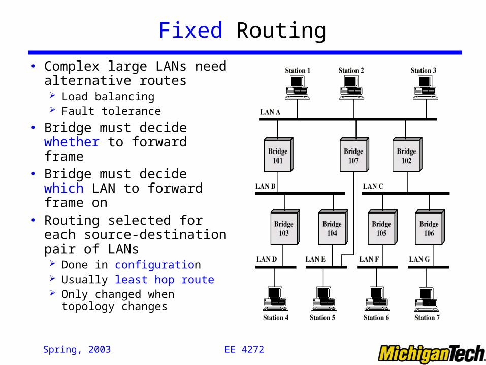
• Complex large LANs need alternative routes Load balancing Fault tolerance
• Bridge must decide whether to forward frame
• Bridge must decide which LAN to forward frame on
• Routing selected for each source-destination pair of LANs Done in configuration Usually least hop route Only changed when topology
changes
EE 4272 Spring, 2003
Spanning Tree
• Bridge automatically develops routing table• Automatically update in response to changes• 3 Mechanisms within the algorithm
Address learning Frame forwarding Loop resolution
EE 4272 Spring, 2003
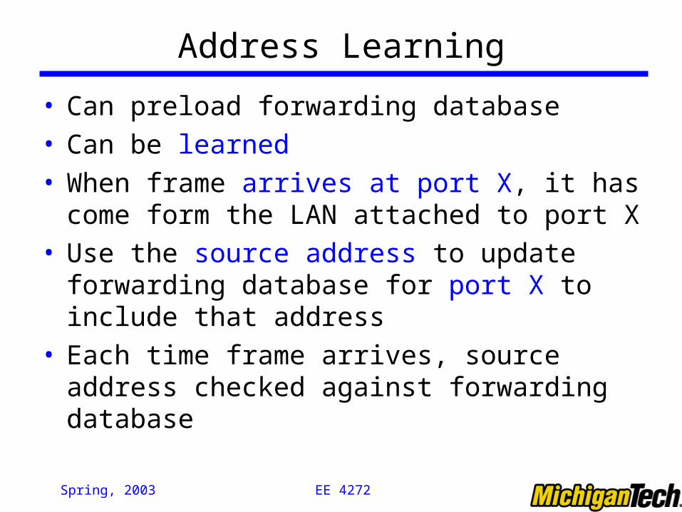
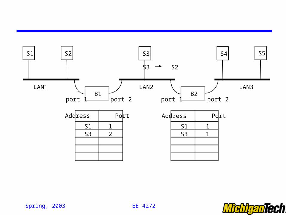
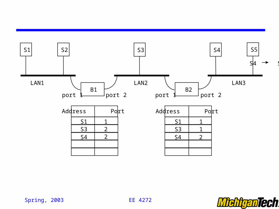
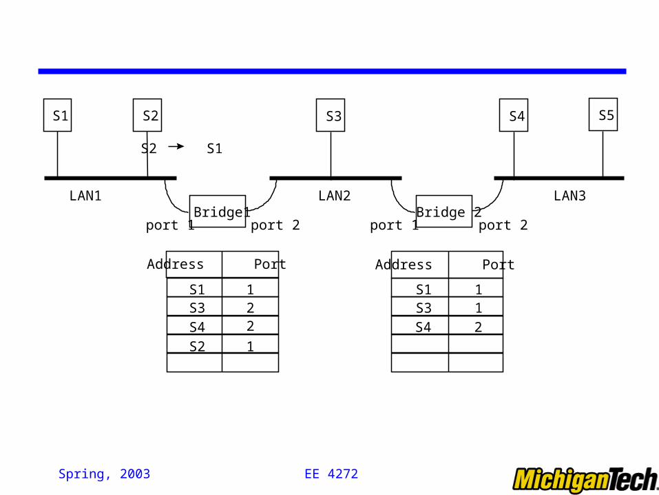
Address Learning
• Can preload forwarding database• Can be learned• When frame arrives at port X, it has come form the
LAN attached to port X• Use the source address to update forwarding database
for port X to include that address• Each time frame arrives, source address checked
against forwarding database

EE 4272 Spring, 2003
B1
S1 S2
B2
S3 S4 S5
Address Port Address Port
port 1 port 2 port 1 port 2
LAN1 LAN2 LAN3
S1 S5
S1 1 S1 1
EE 4272 Spring, 2003
B1
S1 S2
B2
S3 S4 S5
Address Port Address Port
port 1 port 2 port 1 port 2
LAN1 LAN2 LAN3
S3 S2
S1 1 S1 1S3 2 S3 1
EE 4272 Spring, 2003
B1
S1 S2
B2
S3 S4 S5
Address Port Address Port
port 1 port 2 port 1 port 2
LAN1 LAN2 LAN3
S4 S3
S1 1 S1 1S3 2 S3 1
S4 2S4 2
EE 4272 Spring, 2003
Bridge1
S1 S2
Bridge 2
S3 S4 S5
Address Port Address Port
port 1 port 2 port 1 port 2
LAN1 LAN2 LAN3
S2 S1
S1 1 S1 1S3 2 S3 1
S4 2S4 2
S2 1
EE 4272 Spring, 2003
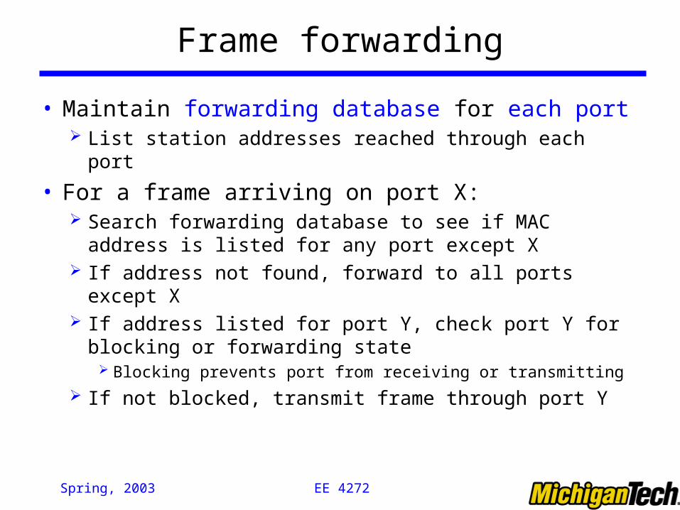
Frame forwarding
• Maintain forwarding database for each port List station addresses reached through each port
• For a frame arriving on port X: Search forwarding database to see if MAC address is listed
for any port except X If address not found, forward to all ports except X If address listed for port Y, check port Y for blocking or
forwarding state Blocking prevents port from receiving or transmitting
If not blocked, transmit frame through port Y
EE 4272 Spring, 2003
Spanning Tree Algorithm
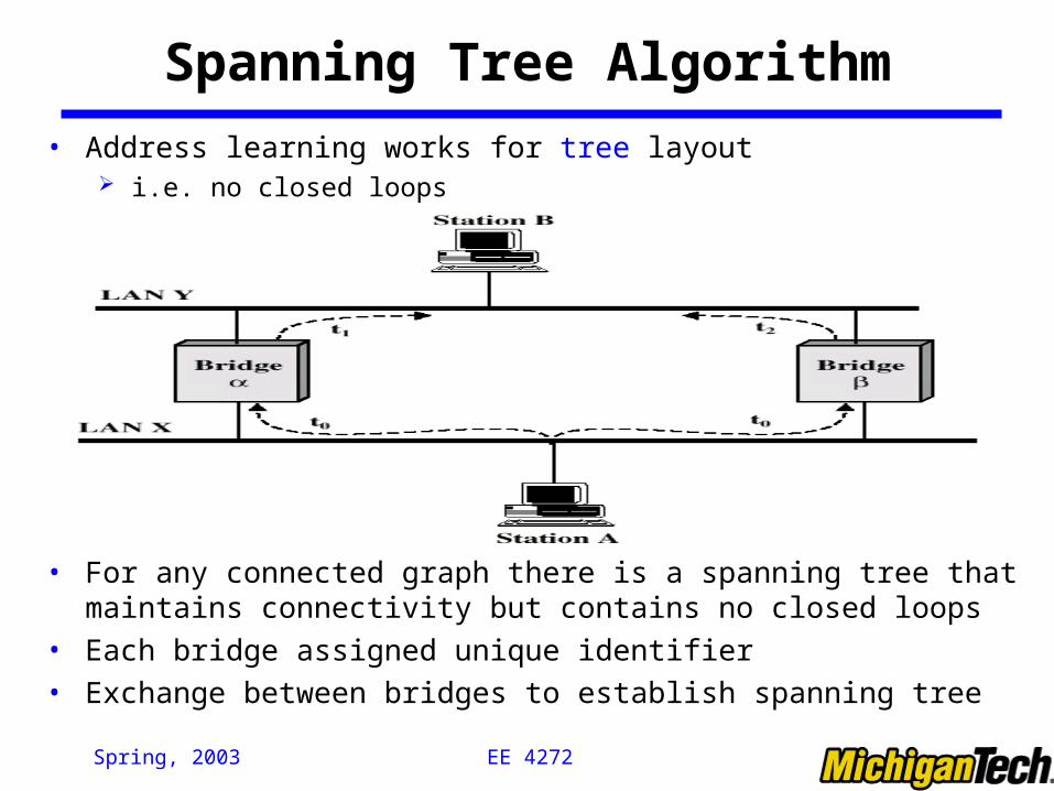
• Address learning works for tree layout i.e. no closed loops
• For any connected graph there is a spanning tree that maintains connectivity but contains no closed loops
• Each bridge assigned unique identifier
• Exchange between bridges to establish spanning tree
EE 4272 Spring, 2003
Loop in Spanning Tree Algorithm of LAN Bridge
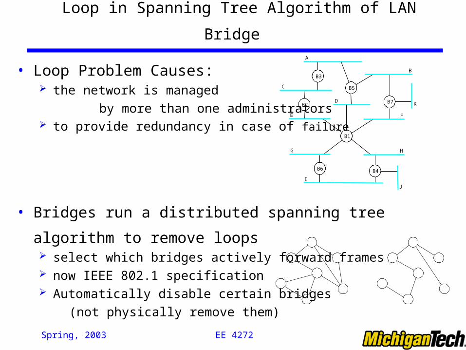
• Loop Problem Causes: the network is managed
by more than one administrators to provide redundancy in case of failure
• Bridges run a distributed spanning tree algorithm to remove loops select which bridges actively forward frames now IEEE 802.1 specification Automatically disable certain bridges
(not physically remove them)
B3
A
C
E
DB2
B5
B
B7 K
F
H
B4
J
B1
B6
G
I